JP2016092496A - Positioning sheet for protective sheet and positioning sheet with protective sheet - Google Patents
Positioning sheet for protective sheet and positioning sheet with protective sheet Download PDFInfo
- Publication number
- JP2016092496A JP2016092496A JP2014222275A JP2014222275A JP2016092496A JP 2016092496 A JP2016092496 A JP 2016092496A JP 2014222275 A JP2014222275 A JP 2014222275A JP 2014222275 A JP2014222275 A JP 2014222275A JP 2016092496 A JP2016092496 A JP 2016092496A
- Authority
- JP
- Japan
- Prior art keywords
- sheet
- protective sheet
- positioning
- protective
- display screen
- Prior art date
- Legal status (The legal status is an assumption and is not a legal conclusion. Google has not performed a legal analysis and makes no representation as to the accuracy of the status listed.)
- Pending
Links
Images


Abstract
Description
本発明は、電子機器の表示画面に対する保護シートの貼着位置を決定するための保護シート用位置決めシートに関し、特に、保護シートの貼着位置の位置決め後に、保護シートを表示画面に貼着する作業で位置ずれが生じることを防止する構造に特徴がある。 TECHNICAL FIELD The present invention relates to a protective sheet positioning sheet for determining a position where a protective sheet is attached to a display screen of an electronic device, and in particular, an operation for attaching a protective sheet to a display screen after positioning the protective sheet. The structure is characterized by preventing the occurrence of misalignment.
従来、特許文献1で示すように、スマートフォンやタブレット端末等の電子機器の表示画面に対して、保護シートを貼着する際に、保護シートの貼着位置を決定するための透明のガイドシートは知られている。この様なガイドシートは、保護シートの非粘着面に重合され、位置決めのためのガイドマークAが表示される。そして、電子機器の表示画面に、ガイドマークBを表示させ、ユーザが、表示画面に表示されたガイドマークBと、ガイドシートのガイドマークAとが一致するように、保護シートの貼着位置を調節しながら、保護シートの粘着面を表示画面に貼着することができる。その後に、ガイドシートを保護シートから剥がす。
Conventionally, as shown in
特許文献1に記載のガイドシートでは、ガイドシートを用いて保護シートの貼着位置を決定することができるが、保護シートを表示画面に貼着する作業において、ユーザが、手振れ等により、決定した貼着位置に保護シートを貼れない位置ずれが生じ易かった。
In the guide sheet described in
そこで、本発明は、保護シートの貼着位置の位置決め後に、保護シートを表示画面に貼着する作業で位置ずれが生じることを防止することができる保護シート用位置決めシート及び保護シート付位置決めシートを提供することを目的とする。 Therefore, the present invention provides a positioning sheet for a protective sheet and a positioning sheet with a protective sheet, which can prevent the occurrence of displacement in the operation of sticking the protective sheet to the display screen after positioning the protective sheet. The purpose is to provide.
(1)上記課題を解決するために、本発明の一局面は、電子機器の表示画面に対する保護シートの貼着位置を決定するための保護シート用位置決めシートであって、その一方面に着脱自在に前記保護シートの粘着面が貼り付けられ、切り込み部が形成されて、この切り込み部によって複数の分割領域に分割可能に形成され、その他方面における、少なくとも何れか一つの分割領域に滑り止め部が形成された、ことを特徴とする。 (1) In order to solve the above-described problem, one aspect of the present invention is a protective sheet positioning sheet for determining a sticking position of a protective sheet to a display screen of an electronic device, and is detachable on one surface thereof. The adhesive surface of the protective sheet is affixed, a cut portion is formed, the cut portion is formed so as to be divided into a plurality of divided regions, and at least any one divided region in the other direction has a non-slip portion. Formed.
上記構成によれば、ユーザが、保護シート用位置決めシートを介して、保護シートを電子機器の表示画面上に配置し、この配置位置を調整して保護シートの貼着位置を決定し、この後、ユーザが、保護シートの上から指等で滑り止め部を電子機器(表示画面等)に対して押し付けながら、保護シート用位置決めシートを上方に摘んで引っ張る。このとき、切り込み部によって、保護シート用位置決めシートが分割される。分割領域のうち滑り止め部が形成されていない領域を保護シートの粘着面から切り込み部に沿って剥がしつつ、保護シート用位置決めシートが剥がされた箇所から、表示画面に順次貼着していく。その後に、残りの保護シート用位置決めシートを保護シートから剥がしつつ、この位置決めシートが剥がされた保護シートの部分を表示画面に貼着する。この様に、滑り止め部を保護シートの上から指等で押圧して固定しながら、保護シート用位置決めシートの分割作業、及び、この分割された保護シート用位置決めシートを保護シートから剥がす作業を行うことができるため、保護シートの実際の貼着位置が貼着位置として決定した位置からずれてしまうことを防止することができる。また、位置決めシートにおける、押圧するのに好適な位置を滑り止め部によってユーザに示すことができる。更に、上記構成では、保護シート用位置決めシートを切り込み部によって分割し、分割領域の一部のみを保護シートから剥がして、この位置決めシートが剥がされた部分のみをまず、表示画面に貼着し、その後に、残りの位置決めシートを保護シートから剥がして、保護シートにおける残りの部位を表示画面に貼着する。このため、保護シートの粘着面全域を一度に表示画面に貼着するよりも、保護シートを表示画面に対して貼着する作業が容易になり、保護シートの実際の貼着位置が貼着位置として決定した位置からずれてしまうことを防止することができる。 According to the above configuration, the user arranges the protective sheet on the display screen of the electronic device via the protective sheet positioning sheet, adjusts the arrangement position, determines the attachment position of the protective sheet, and thereafter The user grips and pulls the protective sheet positioning sheet upward while pressing the anti-slip portion against the electronic device (display screen or the like) with a finger or the like from above the protective sheet. At this time, the positioning sheet for protective sheet is divided by the notch. Of the divided regions, the region where the anti-slip portion is not formed is peeled off from the adhesive surface of the protective sheet along the cut portion, and the protective sheet positioning sheet is sequentially attached to the display screen. Thereafter, the remaining protective sheet positioning sheet is peeled off from the protective sheet, and the part of the protective sheet from which the positioning sheet has been peeled off is adhered to the display screen. In this way, the work for separating the protective sheet positioning sheet and the work for removing the divided protective sheet positioning sheet from the protective sheet while pressing the anti-slip portion on the protective sheet with a finger or the like to fix it. Since it can perform, it can prevent that the actual sticking position of a protection sheet will shift from the position determined as a sticking position. Moreover, the position suitable for pressing in a positioning sheet can be shown to a user by a non-slip | skid part. Further, in the above configuration, the protective sheet positioning sheet is divided by the cut portion, only a part of the divided area is peeled off from the protective sheet, and only the part where the positioning sheet is peeled off is first attached to the display screen, Thereafter, the remaining positioning sheet is peeled off from the protective sheet, and the remaining part of the protective sheet is attached to the display screen. For this reason, the work of sticking the protective sheet to the display screen is easier than sticking the entire adhesive surface of the protective sheet to the display screen at once, and the actual sticking position of the protective sheet is the sticking position. Can be prevented from deviating from the position determined as.
(2)上記切り込み部は、直線状に延びるように形成されており、上記滑り止め部には、ユーザの指を置く領域が、前記切り込み部の延びる方向に並んで、複数設けられていてもよい。 (2) The cut portion is formed so as to extend linearly, and the anti-slip portion may be provided with a plurality of regions where a user's finger is placed side by side in the extending direction of the cut portion. Good.
上記構成によれば、滑り止め部には、ユーザの指を置く領域が複数設けられているため、指で押された部位を中心に、保護シート用位置決めシートが回転して、位置ずれを起こしてしまうことを防止することができる。また、切り込み部が直線状に延びるように形成され、ユーザの指を置く領域は、切り込み部の延びる方向に並んで設けられている。このため、ユーザが指等で滑り止め部を保護シートの上から押さえた状態で、切り込み部から滑り止め部の位置の反対側に向かって位置決めシートを剥がしながら、保護シートを表示画面に貼着していくことができる。これによって、保護シートを表示画面に貼着する操作が容易になる。 According to the above configuration, since the anti-slip portion is provided with a plurality of regions where the user's finger is placed, the positioning sheet for the protective sheet rotates around the portion pressed by the finger to cause a positional shift. Can be prevented. Further, the cut portion is formed so as to extend linearly, and the region where the user's finger is placed is provided side by side in the extending direction of the cut portion. For this reason, the user sticks the protective sheet on the display screen while peeling the positioning sheet from the notch to the opposite side of the anti-slip part while holding the anti-slip part on the protective sheet with a finger. Can continue. This facilitates the operation of attaching the protective sheet to the display screen.
(3)上記切り込み部は、前記一方面まで貫通しないように、前記他方面に形成されていてもよい。 (3) The said notch part may be formed in the said other surface so that it may not penetrate to the said one surface.
上記構成によれば、保護シートを表示画面に貼着する際に、切り込み部で位置決めシートを割ることで、位置決めシートが分割される。切り込み部が他方面から一方面に貫通するように形成されている場合には、一方面の切り込み部のエッジによって、保護シートが傷み易くなるが、上記構成では、一方面に切り込み部のエッジが形成されないため、保護シートが傷むことを防止することができながら、位置決めシートを分割可能にすることができる。 According to the said structure, when sticking a protective sheet on a display screen, a positioning sheet is divided | segmented by dividing a positioning sheet by a notch part. When the cut portion is formed so as to penetrate from the other surface to the one surface, the protective sheet is easily damaged by the edge of the cut portion on the one surface, but in the above configuration, the edge of the cut portion is formed on the one surface. Since it is not formed, the positioning sheet can be divided while preventing the protective sheet from being damaged.
(4)前記滑り止め部は、ポリウレタン製シートで形成されていてもよい。 (4) The anti-slip portion may be formed of a polyurethane sheet.
上記構成によれば、滑り止め部が保護シートの上から指等で表示画面に対して押されたときに、表示画面を傷つけ難く、かつ、ウレタン吸着によって位置決めシートが表示画面から滑り難い。 According to the above configuration, when the anti-slip portion is pushed against the display screen with a finger or the like from above the protective sheet, the display screen is not easily damaged, and the positioning sheet is difficult to slip from the display screen due to urethane adsorption.
(5)上記滑り止め部の厚みは、0.05mm以上、0.5mm以下であってもよい。 (5) The non-slip portion may have a thickness of 0.05 mm or more and 0.5 mm or less.
上記構成によれば、上記滑り止め部の厚みが0.05mm以上あることで、滑り止め効果を十分確保することができ、更に、0.5mm以下であることで、位置決めシートと表示画面との間隔が広くなりすぎて、保護シートを表示画面に貼着する作業で位置ずれが生じることを効果的に防止することができる。 According to the above configuration, the anti-slip effect can be sufficiently secured when the thickness of the anti-slip portion is 0.05 mm or more, and further, the distance between the positioning sheet and the display screen is 0.5 mm or less. It is possible to effectively prevent the positional deviation from occurring in the operation of attaching the protective sheet to the display screen because it is too wide.
(6)上記(1)から(5)の何れかに記載の保護シート用位置決めシートと、前記保護シート用位置決めシートの一方面に、その粘着面が貼り付けられた前記保護シートと、を備えたことを特徴とする保護シート付位置決めシートである。 (6) The protective sheet positioning sheet according to any one of (1) to (5), and the protective sheet having an adhesive surface attached to one surface of the protective sheet positioning sheet. This is a positioning sheet with a protective sheet.
上記構成によれば、上記(1)の発明と同様の作用効果を奏する。 According to the said structure, there exists an effect similar to invention of said (1).
上記構成によって、保護シートの貼着位置の位置決め後に、保護シートを表示画面に貼着する作業で位置ずれが生じることを防止することができる保護シート用位置決めシートを提供することができる。 By the said structure, the positioning sheet for protective sheets which can prevent that a position shift arises by the operation | work which sticks a protective sheet on a display screen after positioning of the sticking position of a protective sheet can be provided.
以下に、本発明の一実施形態にかかる保護シート付位置決めシートについて説明する。 Below, the positioning sheet | seat with a protection sheet concerning one Embodiment of this invention is demonstrated.
(保護シート用位置決めシートの構成)
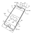
まず、図1から図3を参照して、本実施形態に係る保護シート付位置決めシートの構成を説明する。図1は、本実施形態にかかる、保護シート付位置決めシートの斜視図である。図2は、図1で示す保護シート付位置決めシートを矢印Aの方向から見た側面図である。図3は、保護シート付位置決めシートを電子機器の表示画面に配置した状態を示す図である。なお、本実施形態の説明にあたって、図2における手前を「右」、図2における奥を「左」、図2における右を「後」、図2における左を「前」、図2における「上」を「上」、図2における「下」を「下」として説明する。
(Configuration of protective sheet positioning sheet)
First, with reference to FIGS. 1 to 3, the configuration of a positioning sheet with a protective sheet according to the present embodiment will be described. FIG. 1 is a perspective view of a positioning sheet with a protective sheet according to the present embodiment. FIG. 2 is a side view of the positioning sheet with a protective sheet shown in FIG. FIG. 3 is a diagram illustrating a state in which the positioning sheet with the protective sheet is arranged on the display screen of the electronic device. In the description of the present embodiment, the front side in FIG. 2 is “right”, the back side in FIG. 2 is “left”, the right side in FIG. 2 is “rear”, the left side in FIG. ”Is assumed to be“ upper ”, and“ lower ”in FIG. 2 is assumed to be“ lower ”.
本実施形態にかかる保護シート付位置決めシート100は、電子機器の表示画面を保護するためにこの表示画面をカバーするための保護シート2と、電子機器の表示画面に対する保護シートの貼着位置を決定するための保護シート用位置決めシート1(以下、「位置決めシート1」と記載する)とを重ねてなる。電子機器は、例えば、スマートフォン、タブレット型コンピュータ、携帯型ゲーム機、PDA、デジタルカメラ、パーソナルコンピュータ、ポータブルメディアプレーヤ等の表示画面を備えた機器である。
The positioning sheet with
保護シート2は、例えば、PET、ポリカーボネート、アクリル、ポリウレタン、シリコン等で形成された透明なシートである。保護シート2の一方面に粘着面が形成される。この粘着面は、例えば、粘着剤が塗布されることで形成され、保護シート2の粘着面によって、保護シート2を位置決めシート1の一方面(上面)及び電子機器3の表示画面31に着脱自在に貼着することができるようになっている。図3を参照して、保護シート2は、電子機器3の特定の部材をカバーしないようにするために形成された切欠き部21、23及び貫通孔22を有する。例えば、切欠き部21は、電子機器3の操作ボタン32をカバーしないために形成されている。切欠き部23は、電子機器3のスピーカ33をカバーしないために形成されている。貫通孔22は、電子機器3のセンサー34をカバーしないために形成されている。
The
保護シート用位置決めシート1は、例えば、ポリエチレンテレフタレート樹脂(PET)、ポリカーボネート、アクリル、ポリウレタン、シリコン等で形成された、平面視で四角形の透明のシートである。なお、位置決めシート1の材料は、特にPETが好ましい。位置決めシート1は、例えば0.03mm以上、0.1mm以下の厚みを有する。位置決めシート1は、その一方面(上面)に着脱自在に保護シート2の粘着面が貼り付けられる。
The protective
位置決めシート1は、その他方面(下面)に、位置決めのためのガイドマーク13が設けれている。ガイドマーク13(131、132、133、134)は、図3で示すように、本実施形態では、保護シート2を電子機器3の表示画面31に正確に位置決めした状態で、平面視において、電子機器3の所定の部材の配置位置と重なる位置に設けられている。本実施形態では、位置決めシート1における電子機器3の表示画面31の縁に重なる位置に、ガイドマーク131が形成されている。位置決めシート1における電子機器3の操作ボタン32の縁に重なる位置に、ガイドマーク132が設けられている。また、位置決めシート1における電子機器3のスピーカ33の縁に重なる位置に、ガイドマーク133が設けられている。位置決めシート1における電子機器3のセンサー34の縁に重なる位置に、ガイドマーク134が設けられている。なお、本実施形態では、ガイドマーク13は、平面視において、電子機器3の所定の部材の配置位置と重なる位置に設けられているが、この限りではなく、表示画面31にマークを含む画像を表示させ、このマークに重なる位置に設けられる構成としてもよい。また、保護シート2にガイドマークが設けられている構成等の場合には、位置決めシート1にガイドマーク131が形成されていなくてもよい。
The
なお、各ガイドマーク13は、グラビア印刷によって設けられているが、他の方法によって設けられていてもよい。また、本実施形態では、位置決めシート1には、その他方面(下面)に各ガイドマーク13が設けられているが、その一方面(上面)に設けられていてもよい。また、複数のガイドマーク13の一部がその他方面(下面)に設けられ、複数のガイドマーク13の残りがその一方面(上面)に設けられていてもよい。言い換えれば、位置決めシート1の一方面(上面)及び/又は他方面(下面)に、位置決めのためのガイドマーク13が設けられていればよい。また、本実施形態では、ガイドマーク13は、複数設けられているが、単数設けられていてもよい。
Each
位置決めシート1は、切り込み部11が形成されて、この切り込み部11によって複数の分割領域に分割可能に形成されている。本実施形態では、切り込み部11が一つ形成されて、位置決めシート1は、2つに分割可能に形成されている。なお、3つ以上に分割可能に形成されてもよい。切り込み部11は、直線状に延びるように形成されている。本実施形態では、切り込み部11は、位置決めシート1の左端から右端まで、左右方向に直線状に延びるように形成されている。これによって、切り込み部11によって、後側の分割領域1Aと、前側の分割領域1Bとに分割可能になっている。なお、切り込み部11は、必ずしも左右方向に延びるように形成される必要がなく、前後方向等の他の方向に延びるように形成されてもよい。また、切り込み部11は、必ずしも直線状に形成される必要はなく、円弧状等に形成されてもよい。
The
切り込み部11は、一方面(上面)まで貫通しないように、他方面(下面)に形成されている。この構成によれば、保護シート2を電子機器3の表示画面31に貼着する際に、切り込み部11で位置決めシート1を割ることで、位置決めシート1が分割される。なお、切り込み部11が他方面(下面)から一方面(上面)に貫通するように形成されている場合には、一方面の切り込み部11のエッジによって、保護シート2が傷み易くなるが、上記構成では、一方面に切り込み部11のエッジが形成されないため、保護シート2が傷むことを防止することができながら、位置決めシート1を分割可能にすることができる。また、位置決めシート1に保護シート2を貼着した後に、切り込み部11を入れる場合には、切り込み部11を一方面(上面)まで貫通させてしまうと、保護シート2まで切り込まれてしまい、傷が付く可能性がある。本実施形態では、切り込み部11が一方面(上面)まで貫通しないため、保護シート2まで切り込まれてしまうことを防止することができる。
The
位置決めシート1には、その他方面における、少なくとも何れか一つの分割領域に滑り止め部12が形成されている。本実施形態では、前側の分割領域1Bに滑り止め部12が形成されている。なお、前側の分割領域1Bに代えて、又は前側の分割領域1Bとともに、後ろ側の分割領域1Aに、滑り止め部12が形成されていてもよい。滑り止め部12は、平面視において、切り込み部11の延びる方向に並ぶ2つの円を繋いだような形状を有しており、各円の部分がそれぞれ指を置く領域121、122になっている。これによって、滑り止め部12には、ユーザの指を置く領域121、122が、切り込み部11の延びる方向に並んで、複数(2つ)設けられることになる。この様に、滑り止め部12には、ユーザの指を置く領域121、122が複数設けられているため、指で押された部位を中心に、位置決めシート1が回転して、位置ずれを起こしてしまうことを防止することができる。また、上述したように、切り込み部11が直線状に延びるように形成されているが、ユーザの指を置く領域121、122は、切り込み部11の延びる方向に並んで設けられている。このため、ユーザが指等で滑り止め部12を保護シート2の上から押さえた状態で、切り込み部11から滑り止め部12の位置の反対側(後ろ側)に向かって位置決めシート1を剥がしながら、保護シート2を電子機器3の表示画面31に貼着していく作業がし易くなる。これによって、保護シート2を表示画面31に貼着する操作が容易になる。
The
なお、本実施形態では、2つの領域121、122が設けられているが、3つ以上のユーザの指を置く領域が設けられていても、1つのユーザの指を置く領域が設けられていてもよい。なお、3つ以上のユーザの指を置く領域が設けられる場合には、そのうち少なくとも2つは、本実施形態の領域121、122のように、切り込み部11の延びる方向に並んで配置されることが好ましい。
In this embodiment, two
滑り止め部12は、ポリウレタン製シートが位置決めシート1に貼着されることで形成されている。なお、滑り止め部12は、ポリウレタン製シートを貼着して形成されるに限定されず、他の材料から成るシートを貼着して形成されても、粘着剤等を塗布することで形成されてもよい。もっとも、ポリウレタン製シートが、滑り止め部12が保護シート2の上から指等で表示画面31に対して押されたときに、表示画面31を傷つけ難く、かつ、ウレタン吸着によって位置決めシート1が表示画面31から滑り難いため、好ましい。なお、滑り止め部12の下面は、表示画面31を傷つけないように、マット加工されていることが好ましい。
The
滑り止め部12の厚みは、0.05mm以上、0.5mm以下である。滑り止め部12の厚みが0.05mm以上あることで、滑り止め効果を十分確保することができ、更に、0.5mm以下であることで、位置決めシート1と表示画面31との間隔が広くなりすぎて、保護シート2を表示画面31に貼着する作業で位置ずれが生じることを効果的に防止することができる。
The thickness of the anti-slip | skid
図1で示すように、位置決めシート1の前端部と後端部には、それぞれ十字マーク14が設けられている。なお、十字マーク14は、本実施形態では、位置決めシート1の下面に設けられている。十字マーク14は、保護シート2を貼り付けた状態の位置決めシート1を製造する際に、保護シート2の裁断位置を決定するために使用される。なお、十字マーク14については、図面の視認性を考慮して、図1の他の図面においては図示を省略する。
As shown in FIG. 1, cross marks 14 are provided on the front end portion and the rear end portion of the
(保護シートの貼着方法)
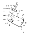
以下に、図4から図6を用いて、保護シート2を電子機器3の表示画面31に貼着する方法を説明する。まず、図4で示すように、ユーザが、保護シート付位置決めシート100を電子機器3の表示画面31が形成された側に配置する。ここで、保護シート付位置決めシート100を、保護シート2が位置決めシート1を介して電子機器3の上に配置されるように、すなわち、保護シート2が上で位置決めシート1が下になるように、電子機器3の上に配置する。このとき、位置決めシート1のガイドマーク13が、平面視において、電子機器3の所定の部材と重なるように、保護シート付位置決めシート100の配置位置を調整する。具体的には、電子機器3の表示画面31の縁にガイドマーク131が重なり、電子機器3の操作ボタン32の縁にガイドマーク132が重なり、電子機器3のスピーカ33の縁にガイドマーク133が重なり、電子機器3のセンサー34の縁にガイドマーク134が重なるように、保護シート付位置決めシート100の配置位置を調整する。これによって、保護シート2の貼着位置を決定する。
(Protection sheet attachment method)
Below, the method of sticking the
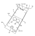
この後、ユーザが保護シート2の上から滑り止め部12を電子機器3の表示画面31に対して押す。具体的には、ユーザが、その一方の手(図4では左手)の1本の指(図4では左手中指)で滑り止め部12の領域121を押し、別の1本の指(図4では左手人指し指)で滑り止め部12の領域122を押す。この様に、滑り止め部12によって、ユーザが押圧すべき位置を示すことができる。この状態で、図5で示すように、他方の手(図4では右手)によって、位置決めシート1における、切り込み部11を基準として滑り止め部12の反対側端部を保護シート2とともに摘まんで上方に引っぱる。これによって、位置決めシート1が切り込み部11で割れて前側の分割領域1Bと後側の分割領域1Aとに分割される。そして、位置決めシート1における後側の分割領域1Aを、切り込み部11から後端に向かって保護シート2から剥がしながら、保護シート2を表示画面31に対して貼着していく。この様に、滑り止め部12を保護シート2の上から指等で押圧して固定しながら、位置決めシート1の分割作業、及び、この分割された位置決めシート1を保護シート2から剥がす作業を行うことができるため、保護シート2の実際の貼着位置が貼着位置として決定した位置からずれてしまうことを防止することができる。
Thereafter, the user presses the
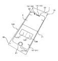
次に、図6を参照して、位置決めシート1における前側の分割領域1Bを切り込み部11から前端に向かって剥がしながら、保護シート2を電子機器3の表示画面31に対して貼着する。この構成では、位置決めシート1を切り込み部11によって分割し、分割領域の一部のみ(後側の分割領域1A)を保護シート2から剥がして、この位置決めシート1が剥がされた部分(後半分)のみをまず、表示画面31に貼着し、その後に、残りの位置決めシート1(前側の分割領域1B)を保護シート2から剥がして、保護シート2における残りの部分(前半分)を表示画面31に貼着する。このため、保護シート2の粘着面全域を一度に表示画面31に貼着するよりも、保護シート2を表示画面31に対して貼着する作業が容易になり、保護シート2の実際の貼着位置が貼着位置として決定した位置からずれてしまうことを防止することができる。
Next, referring to FIG. 6, the
(保護シート用位置決めシートの製造方法)
次に、本実施形態に係る保護シート付位置決めシート100の製造方法の一例を説明する。まず、保護シート2、位置決めシート1を製造するための長尺なシートをそれぞれ形成する。位置決めシート1を製造するための長尺なシートに、ガイドマーク13及び十字マーク14のセットを、長尺方向に沿って複数個プリント印刷する。更に、位置決めシート1の短尺方向に沿って直線状に切り込み部11となる切り込みを形成する。また、保護シート2を製造するためのシートの一方面にわたって粘着面を形成する。保護シート2、位置決めシート1を製造するための長尺なシートをそれぞれロール状とする。なお、保護シート2を製造するためのシートのロールを保護シート用ロールとし、位置決めシート1を製造するためのシートのロールを位置決めシート用ロールと記載する。
(Method for manufacturing positioning sheet for protective sheet)
Next, an example of the manufacturing method of the positioning sheet with
そして、保護シート用ロールの一端から保護シート2を製造するためのシートを引き出し、位置決めシート用ロールの一端から位置決めシート1を製造するためのシートを引き出し、保護シート2を製造するためのシートの粘着面と、位置決めシート1を製造するためのシートのガイドマーク13及び十字マーク14の形成側とは反対側とを、貼着させる。なお、この貼着は、保護シート2を製造するためのシートの粘着面によって行われる。
And the sheet | seat for manufacturing the
この後、十字マーク14の位置をセンサで検知することで保護シート2の裁断位置を決定して、裁断機によって保護シート2を製造するためのシートを、保護シート2の形状に切断していく。この工程の後、長尺の位置決めシート1に複数の保護シート2が貼着されているもの出来る。その後、位置決めシート1を製造するためのシートを、長尺方向に沿って所定の間隔毎にカットしていく。この様にして、保護シート付位置決めシート100が製造される。
Thereafter, the position of the
(変形例)
(1)本実施形態では、滑り止め部12は、切り込み部11の延びる方向に並ぶ2つの円を繋いだような形状を有しており、各円の部分がそれぞれ指を置く領域121、122になっているが、図7で示す滑り止め部12Aのように領域121、122は、繋がっておらず、離間していてもよい。
(Modification)
(1) In the present embodiment, the
(2)また、滑り止め部12は、切り込み部11の延びる方向に並ぶ2つの円を繋いだような形状を有しているが、この様な形状に限定されず、例えば、図8で示す滑り止め部12Bのように矩形であってもよい。更に、図9で示す滑り止め部12Cのように、矩形の指を置く領域121´、122´が離間していてもよい。
(2) Further, the
1 保護シート用位置決めシート
1A、1B 分割領域
11 切り込み部
12 滑り止め部
13 ガイドマーク
2 保護シート
3 電子機器
100 保護シート付位置決めシート
DESCRIPTION OF
Claims (6)
その一方面に着脱自在に前記保護シートの粘着面が貼り付けられ、
切り込み部が形成されて、この切り込み部によって複数の分割領域に分割可能に形成され、
その他方面における、少なくとも何れか一つの分割領域に滑り止め部が形成された、
ことを特徴とする保護シート用位置決めシート。 It is a positioning sheet for a protective sheet for determining the attachment position of the protective sheet to the display screen of the electronic device,
The adhesive surface of the protective sheet is detachably attached to one side of the surface,
A cut portion is formed, and the cut portion is formed so as to be divided into a plurality of divided regions.
In the other direction, a non-slip portion is formed in at least one of the divided regions,
A positioning sheet for a protective sheet.
前記滑り止め部には、ユーザの指を置く領域が、前記切り込み部の延びる方向に並んで、複数設けられている、
ことを特徴とする請求項1に記載の保護シート用位置決めシート。 The cut portion is formed to extend linearly,
In the non-slip portion, a plurality of regions where a user's finger is placed are provided side by side in the direction in which the cut portion extends,
The positioning sheet for a protective sheet according to claim 1.
ことを特徴とする請求項1又は2に記載の保護シート用位置決めシート。 The cut portion is formed on the other surface so as not to penetrate to the one surface.
The positioning sheet for a protective sheet according to claim 1 or 2, wherein the positioning sheet is a protective sheet.
ことを特徴とする請求項1から3の何れかに記載の保護シート用位置決めシート。 The anti-slip portion is formed of a polyurethane sheet,
The positioning sheet for a protective sheet according to any one of claims 1 to 3, wherein the positioning sheet is a protective sheet.
ことを特徴とする請求項4に記載の保護シート用位置決めシート。 The thickness of the anti-slip part is 0.05 mm or more and 0.5 mm or less,
The positioning sheet for a protective sheet according to claim 4, wherein:
前記保護シート用位置決めシートの一方面に、その粘着面が貼り付けられた前記保護シートと、
を備えたことを特徴とする保護シート付位置決めシート。 A positioning sheet for a protective sheet according to any one of claims 1 to 5,
On the one surface of the protective sheet positioning sheet, the protective sheet with the adhesive surface attached,
A positioning sheet with a protective sheet, comprising:
Priority Applications (1)
| Application Number | Priority Date | Filing Date | Title |
|---|---|---|---|
| JP2014222275A JP2016092496A (en) | 2014-10-31 | 2014-10-31 | Positioning sheet for protective sheet and positioning sheet with protective sheet |
Applications Claiming Priority (1)
| Application Number | Priority Date | Filing Date | Title |
|---|---|---|---|
| JP2014222275A JP2016092496A (en) | 2014-10-31 | 2014-10-31 | Positioning sheet for protective sheet and positioning sheet with protective sheet |
Publications (2)
| Publication Number | Publication Date |
|---|---|
| JP2016092496A true JP2016092496A (en) | 2016-05-23 |
| JP2016092496A5 JP2016092496A5 (en) | 2016-09-29 |
Family
ID=56019830
Family Applications (1)
| Application Number | Title | Priority Date | Filing Date |
|---|---|---|---|
| JP2014222275A Pending JP2016092496A (en) | 2014-10-31 | 2014-10-31 | Positioning sheet for protective sheet and positioning sheet with protective sheet |
Country Status (1)
| Country | Link |
|---|---|
| JP (1) | JP2016092496A (en) |
Cited By (2)
| Publication number | Priority date | Publication date | Assignee | Title |
|---|---|---|---|---|
| JP2018054873A (en) * | 2016-09-29 | 2018-04-05 | 三菱電機株式会社 | Decorative panel set |
| JP2018156038A (en) * | 2017-03-21 | 2018-10-04 | 株式会社サンクレスト | Film pasting jig |
Citations (5)
| Publication number | Priority date | Publication date | Assignee | Title |
|---|---|---|---|---|
| JP3087321U (en) * | 2002-01-16 | 2002-08-02 | 有限会社トラスト | Anti-slip device |
| JP2006206782A (en) * | 2005-01-28 | 2006-08-10 | Nof Corp | Functional film for attaching to flat display and method for attaching the same |
| JP2014012804A (en) * | 2012-07-03 | 2014-01-23 | Naniwa Kako Kk | Protective sheet material, and adhering method of surface protective sheet |
| JP2014065852A (en) * | 2012-09-27 | 2014-04-17 | Hitachi Systems Ltd | Protective film with protective material |
| JP2014102481A (en) * | 2012-07-31 | 2014-06-05 | Hori Co Ltd | Sheet sticking structure, and method of sticking protective sheet using sheet sticking structure |
-
2014
- 2014-10-31 JP JP2014222275A patent/JP2016092496A/en active Pending
Patent Citations (5)
| Publication number | Priority date | Publication date | Assignee | Title |
|---|---|---|---|---|
| JP3087321U (en) * | 2002-01-16 | 2002-08-02 | 有限会社トラスト | Anti-slip device |
| JP2006206782A (en) * | 2005-01-28 | 2006-08-10 | Nof Corp | Functional film for attaching to flat display and method for attaching the same |
| JP2014012804A (en) * | 2012-07-03 | 2014-01-23 | Naniwa Kako Kk | Protective sheet material, and adhering method of surface protective sheet |
| JP2014102481A (en) * | 2012-07-31 | 2014-06-05 | Hori Co Ltd | Sheet sticking structure, and method of sticking protective sheet using sheet sticking structure |
| JP2014065852A (en) * | 2012-09-27 | 2014-04-17 | Hitachi Systems Ltd | Protective film with protective material |
Cited By (2)
| Publication number | Priority date | Publication date | Assignee | Title |
|---|---|---|---|---|
| JP2018054873A (en) * | 2016-09-29 | 2018-04-05 | 三菱電機株式会社 | Decorative panel set |
| JP2018156038A (en) * | 2017-03-21 | 2018-10-04 | 株式会社サンクレスト | Film pasting jig |
Similar Documents
| Publication | Publication Date | Title |
|---|---|---|
| US20160043765A1 (en) | Protective film composite | |
| KR101176316B1 (en) | Application adhesion label and the heteromorphism to attach easily liquid crystal protection film on liquid crystal of smart phone and tablet personal computer | |
| KR101252750B1 (en) | Appartus for attaching protection film for display of mobile electronic device, sheet for attaching protection film for display of mobile electronic device, and method for attaching protection film for display of mobile electronic device | |
| TWM515133U (en) | Display protection film attaching case for mobile terminal | |
| KR101234532B1 (en) | Protecting film for smart device | |
| JP2006155452A (en) | Protection film laminate for touch panel | |
| JP2014028108A5 (en) | ||
| KR101257477B1 (en) | Tool for attaching protection film for display of mobile electronic device, apparatus for attaching protection film for display of mobile electronic device, kit for attaching protection film for display of mobile electronic device, and method for attaching protection film for display of mobile electronic device | |
| US20130313845A1 (en) | Holder for a Flat Plate Such as a Tablet Computer | |
| US20180314298A1 (en) | Screen protector for an electronic device | |
| WO2016166803A1 (en) | Device for affixing film to display screen | |
| JP2013161308A (en) | Positioning mechanism of protective sheet for display screen of electronic device | |
| KR101462266B1 (en) | Screen protective film attaching method using by application | |
| JP2009195410A (en) | Cosmetic tool for eyelid and method for manufacturing the same | |
| JP2016092496A (en) | Positioning sheet for protective sheet and positioning sheet with protective sheet | |
| JP3188866U (en) | Screen protector for portable game consoles | |
| KR200462082Y1 (en) | Protection film to attach in position for mobile terminal display | |
| JP5755973B2 (en) | Form printing sheet and delivery slip | |
| US20200162597A1 (en) | Systems and methods for cleaning and protecting displays of electronic devices | |
| KR101495075B1 (en) | Protection Film Structure With Functional Film | |
| KR101053235B1 (en) | Protective film set and method for fabricating the same | |
| JP2007314622A (en) | Double-sided adhesive sheet | |
| JP2008070762A (en) | Structure and method for protecting display device | |
| JP2016092496A5 (en) | ||
| JP2009028137A (en) | Medical plaster body set |
Legal Events
| Date | Code | Title | Description |
|---|---|---|---|
| A521 | Request for written amendment filed |
Free format text: JAPANESE INTERMEDIATE CODE: A523 Effective date: 20160810 |
|
| A621 | Written request for application examination |
Free format text: JAPANESE INTERMEDIATE CODE: A621 Effective date: 20160810 |
|
| A871 | Explanation of circumstances concerning accelerated examination |
Free format text: JAPANESE INTERMEDIATE CODE: A871 Effective date: 20160810 |
|
| A975 | Report on accelerated examination |
Free format text: JAPANESE INTERMEDIATE CODE: A971005 Effective date: 20160824 |
|
| A131 | Notification of reasons for refusal |
Free format text: JAPANESE INTERMEDIATE CODE: A131 Effective date: 20160830 |
|
| A521 | Request for written amendment filed |
Free format text: JAPANESE INTERMEDIATE CODE: A523 Effective date: 20161031 |
|
| A131 | Notification of reasons for refusal |
Free format text: JAPANESE INTERMEDIATE CODE: A131 Effective date: 20161122 |
|
| A02 | Decision of refusal |
Free format text: JAPANESE INTERMEDIATE CODE: A02 Effective date: 20170523 |