JP2016086594A - Power supply system, power supply apparatus and control method for power supply system - Google Patents
Power supply system, power supply apparatus and control method for power supply system Download PDFInfo
- Publication number
- JP2016086594A JP2016086594A JP2014219445A JP2014219445A JP2016086594A JP 2016086594 A JP2016086594 A JP 2016086594A JP 2014219445 A JP2014219445 A JP 2014219445A JP 2014219445 A JP2014219445 A JP 2014219445A JP 2016086594 A JP2016086594 A JP 2016086594A
- Authority
- JP
- Japan
- Prior art keywords
- power
- power supply
- load
- generation device
- supply system
- Prior art date
- Legal status (The legal status is an assumption and is not a legal conclusion. Google has not performed a legal analysis and makes no representation as to the accuracy of the status listed.)
- Pending
Links
Images


Abstract
Description
本発明は、電力供給システム、電力供給機器及び電力供給システムの制御方法に関するものである。 The present invention relates to a power supply system, a power supply device, and a control method for the power supply system.
太陽電池等の発電設備を備える電力供給システムのパワーコンディショナとして、商用電源系統(以下、適宜、系統と略記する)に連系して交流電力を出力する系統連系運転と、系統と関わりなく交流電力を出力する自立運転とを可能としたものが知られている。また、分散電源として、太陽電池だけでなく例えば発電装置等も備える電力供給システムが知られている。 As a power conditioner of a power supply system equipped with power generation equipment such as solar cells, grid-connected operation that outputs AC power linked to a commercial power system (hereinafter abbreviated as appropriate), regardless of the system There is known one capable of independent operation that outputs AC power. As a distributed power source, a power supply system including not only a solar battery but also a power generation device or the like is known.
このようなパワーコンディショナの中には、系統連系運転のときに余剰電力が発生した場合、系統への売電を可能にするものがある。例えば、特許文献1は、太陽電池(太陽光発電部)にて発電した電力を、系統に売電可能であれば発電装置(ガス発電部)が発電する電力を優先して負荷に供給し、売電が可能でなければ太陽電池からの電力を優先して負荷に供給する、経済的な運用が可能な電力供給システムを開示する。
Among such power conditioners, there is one that makes it possible to sell power to the grid when surplus power is generated during grid interconnection operation. For example,
ここで、近年、売電といった経済性よりも環境を重視し、分散電源のうち環境への負担がより小さいものを優先して使用する電力供給システムへの需要がある。 Here, in recent years, there is a demand for an electric power supply system that places importance on the environment rather than economic efficiency such as power sale and gives priority to the use of a distributed power source with a smaller burden on the environment.
上記のような課題に鑑みてなされた本発明の目的は、環境への負担が小さくなるように複数の分散電源の運転制御が可能な電力供給システム、電力供給機器及び電力供給システムの制御方法を提供することにある。 An object of the present invention made in view of the above problems is to provide a power supply system, a power supply device, and a control method for the power supply system that can control the operation of a plurality of distributed power sources so that the burden on the environment is reduced. It is to provide.
上述した諸課題を解決すべく、本発明に係る電力供給システムは、電力の供給を受ける蓄電池および負荷と、前記電力の供給を行う太陽電池および発電装置と、前記電力を制御する電力供給機器と、所定の電流を検出することで前記発電装置を発電させる電流センサと、を備える電力供給システムであって、前記電力供給機器は、前記太陽電池が発電した電力を前記蓄電池に供給し、余剰電力を前記負荷に供給させて、前記余剰電力によっても不足する電力を前記電流センサが検出する電流を制御することにより前記発電装置から前記負荷に供給させる制御部、を備えることを特徴とする。 In order to solve the above-described problems, a power supply system according to the present invention includes a storage battery and a load that receive power supply, a solar battery and a power generation device that supply the power, and a power supply device that controls the power. A power supply system comprising: a current sensor configured to generate the power generation device by detecting a predetermined current, wherein the power supply device supplies power generated by the solar cell to the storage battery, and surplus power And a control unit that controls the current detected by the current sensor to supply the load from the power generation device to the load.
また、本発明に係る電力供給システムにおいて、前記電力供給機器は、第1電力変換部と、前記第1電力変換部とは異なる第2電力変換部とを更に備え、前記太陽電池からの電力を、前記第1電力変換部を経由させて前記電流センサに前記所定の電流を検出させるとともに前記負荷に供給させる第1経路、及び前記第2電力変換部を経由させて前記負荷に供給させる第2経路を有し、前記余剰電力を前記第2経路によって前記負荷に供給させることが好ましい。 Moreover, in the power supply system according to the present invention, the power supply device further includes a first power conversion unit and a second power conversion unit different from the first power conversion unit, and receives power from the solar cell. A first path that causes the current sensor to detect the predetermined current via the first power converter and supply the load to the load; and a second path that supplies the load to the load via the second power converter. It is preferable to have a route and supply the surplus power to the load through the second route.
また、本発明に係る電力供給システムにおいて、前記電力供給機器は、前記第1電力変換部を用いて前記第1経路を流れる電流を調整することで、前記発電装置から前記負荷に供給させる電力を変化させることが好ましい。 Moreover, the electric power supply system which concerns on this invention WHEREIN: The said electric power supply apparatus adjusts the electric current which flows through the said 1st path | route using the said 1st electric power conversion part, The electric power supplied to the said load from the said electric power generating apparatus is provided. It is preferable to change.
また、本発明に係る電力供給システムにおいて、前記発電装置は燃料電池であって、前記所定の電流は順潮流の電流であることが好ましい。 In the power supply system according to the present invention, it is preferable that the power generation device is a fuel cell, and the predetermined current is a forward current.
さらに、上述した諸課題を解決すべく、本発明に係る電力供給機器は、電力の供給を受ける蓄電池および負荷と、前記電力の供給を行う太陽電池および発電装置と、所定の電流を検出することで前記発電装置を発電させる電流センサと、を備える電力供給システムで用いられる、前記電力を制御する電力供給機器であって、前記太陽電池が発電した電力を前記蓄電池に供給し、余剰電力を前記負荷に供給させて、前記余剰電力によっても不足する電力を前記電流センサが検出する電流を制御することにより前記発電装置から前記負荷に供給させる制御部、を備えることを特徴とする。 Furthermore, in order to solve the above-described problems, a power supply device according to the present invention detects a storage battery and a load that receive power supply, a solar battery and a power generation device that supplies the power, and a predetermined current. A power supply device for controlling the power used in a power supply system comprising a current sensor for generating the power generation device, wherein the power generated by the solar cell is supplied to the storage battery, and surplus power is supplied to the storage battery. A control unit configured to supply the load to the load by controlling the current detected by the current sensor to be supplied to the load and detected by the current sensor even when the surplus power is insufficient.
さらに、上述した諸課題を解決すべく、本発明に係る電力供給システムの制御方法は、電力の供給を受ける蓄電池および負荷と、前記電力の供給を行う太陽電池および発電装置と、前記電力を制御する電力供給機器と、所定の電流を検出することで前記発電装置を発電させる電流センサと、を備える電力供給システムの制御方法であって、前記太陽電池が発電した電力を前記蓄電池に供給し、余剰電力を前記負荷に供給させるステップと、前記余剰電力によっても不足する電力を前記電流センサが検出する電流を制御することにより前記発電装置から前記負荷に供給させるステップと、を有することを特徴とする。 Furthermore, in order to solve the above-described problems, a control method for a power supply system according to the present invention includes a storage battery and a load that receive power supply, a solar battery and a power generation device that supplies the power, and the power control. A power supply system comprising: a power supply device that performs power generation by detecting a predetermined current; and a power sensor that generates power by detecting a predetermined current, the power generated by the solar cell being supplied to the storage battery, Supplying surplus power to the load; and supplying power from the power generator to the load by controlling a current detected by the current sensor for power that is also insufficient due to the surplus power. To do.
本発明に係る電力供給システム、電力供給機器及び電力供給システムの制御方法によれば、環境への負担が小さくなるように複数の分散電源の運転制御が可能である。 According to the power supply system, the power supply device, and the control method for the power supply system according to the present invention, it is possible to control the operation of a plurality of distributed power supplies so as to reduce the burden on the environment.
以降、諸図面を参照しながら、本発明の実施態様を詳細に説明する。 Hereinafter, embodiments of the present invention will be described in detail with reference to the drawings.
(実施の形態)
まず、本発明の一実施形態に係る電力供給システムについて説明する。本実施形態に係る電力供給システムは、系統(商用電源系統)から供給される電力の他に、売電可能な電力を供給する分散電源及び/又は売電不可能な電力を供給する分散電源を備える。売電可能な電力を供給する分散電源は、例えば太陽光発電などによって電力を供給するシステムである。一方売電不可能な電力を供給する分散電源は、例えば電力を充放電することができる蓄電池システム、SOFC(Solid Oxide Fuel Cell)などの燃料電池を含む燃料電池システム、及びガス燃料により発電するガス発電機システムなどである。本実施の形態においては、売電可能な電力を供給する分散電源として太陽電池、及び売電不可能な電力を供給する分散電源として蓄電池と、及び燃料電池又はガス発電機である発電装置とを備える例を示す。
(Embodiment)
First, a power supply system according to an embodiment of the present invention will be described. The power supply system according to the present embodiment includes a distributed power source that supplies power that can be sold and / or a distributed power source that supplies power that cannot be sold, in addition to the power supplied from the system (commercial power system). Prepare. A distributed power source that supplies power that can be sold is a system that supplies power by, for example, solar power generation. On the other hand, a distributed power source that supplies electric power that cannot be sold includes, for example, a storage battery system that can charge and discharge electric power, a fuel cell system that includes a fuel cell such as a SOFC (Solid Oxide Fuel Cell), and a gas that generates power from gas fuel. Such as a generator system. In the present embodiment, a solar battery as a distributed power source that supplies power that can be sold, a storage battery as a distributed power source that supplies power that cannot be sold, and a power generator that is a fuel cell or a gas generator. An example is provided.
(電力供給システムの構成)
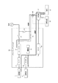
図1は、本発明の一実施形態に係る電力供給システムの概略構成を示すブロック図である。本実施形態に係る電力供給システムは、太陽電池11と、蓄電池12と、パワーコンディショナ20(電力供給機器)と、分電盤31と、負荷32と、発電装置33と、電流センサ40とを備える。ここで、発電装置33は、燃料電池又はガス発電機により構成されるものである。電力供給システムは、通常は系統との連系運転を行い、系統から供給される電力と、各分散電源(太陽電池11、蓄電池12、発電装置33)からの電力とを負荷32に供給する。また、電力供給システムは、停電時など系統からの電力供給がない場合は自立運転を行い、各分散電源(太陽電池11、蓄電池12、発電装置33)からの電力を負荷32に供給する。なお、電力供給システムが自立運転を行う場合には、各分散電源(太陽電池11、蓄電池12、発電装置33)は系統から解列した状態であり、電力供給システムが連系運転を行う場合には、各分散電源(太陽電池11、蓄電池12、発電装置33)は系統と並列した状態となる。
(Configuration of power supply system)
FIG. 1 is a block diagram showing a schematic configuration of a power supply system according to an embodiment of the present invention. The power supply system according to the present embodiment includes a
図1において、各機能ブロックを結ぶ実線は電力の流れる配線を表し、電流センサ40と発電装置33とを結ぶ破線は通信される情報(電流センサ40の検出信号)の流れを表す。ここで、制御部25と多くの機能ブロックとの間には制御信号又は通信される情報の流れがあるが、これらについては後述する。制御信号及び情報の通信は、有線通信としてもよいし、無線通信としてもよい。制御信号及び情報の通信には、各階層含め、様々な方式を採用可能である。例えば、ZigBee(登録商標)などの近距離通信方式による通信を採用することができる。また、赤外線通信、電力線搬送通信(PLC:Power Line Communication)など、様々な伝送メディアを使用することができる。またそれぞれの通信に適した物理層を含む下位の層の上で、各種プロトコル、例えばZigBee SEP2.0(Smart Energy Profile2.0)、ECHONET Lite(登録商標)などのような論理層だけ規定される通信プロトコルを動作させてもよい。
In FIG. 1, a solid line connecting the functional blocks represents a wiring through which power flows, and a broken line connecting the
太陽電池11は、太陽光のエネルギーを直流の電力に変換するものである。太陽電池11は、例えば光電変換セルを有する発電部がマトリクス状に接続され、所定の直流電流(たとえば10A)を出力するように構成される。太陽電池11は、シリコン系多結晶太陽電池、シリコン系単結晶太陽電池、又はCIGS等薄膜系太陽電池等、光電変換可能なものであればその種類は制限されない。
The
蓄電池12は、リチウムイオン電池やニッケル水素電池等の蓄電池から構成される。蓄電池12は、充電された電力を放電することにより、電力を供給可能である。また、蓄電池12は、系統、太陽電池11から供給される電力に加え、発電装置33から供給される電力を充電可能である。
The
パワーコンディショナ20(電力供給機器)は、太陽電池11、蓄電池12から供給される直流の電力と、系統及び発電装置33から供給される交流の電力との変換を行うとともに、連系運転及び自立運転の切り替え制御を行うものである。パワーコンディショナ20は、インバータ21(第1電力変換部)と、連系運転スイッチ22、23と、自立運転スイッチ24と、DC/AC部26(第2電力変換部)と、DC/DC部27〜29と、パワーコンディショナ20全体を制御する制御部25とを備える。なお、連系運転スイッチ23は、パワーコンディショナ20外に出すよう構成しても良い。
The power conditioner 20 (power supply device) converts the DC power supplied from the
DC/DC部27〜29は、インバータ21の前段で直流電力を昇圧又は降圧するものである。例えば、DC/DC部27は、太陽電池11からの直流電力を一定の電圧まで昇圧してインバータ21に供給する。また、DC/DC部28は、蓄電池12からの直流電力を一定の電圧まで昇圧してインバータ21に供給する。また、DC/DC部28は、インバータ21、DC/DC部27あるいはDC/DC部29からの直流電圧を降圧して蓄電池12に供給する。DC/DC部29は、例えばDC/AC部26を通じて発電装置33からの電力を引き込むために設けられる。
The DC /
インバータ21(第1電力変換部)は、双方向インバータであって、太陽電池11、蓄電池12から供給される直流の電力を交流の電力に変換し、また、系統から供給される交流の電力を直流の電力に変換する。
The inverter 21 (first power conversion unit) is a bidirectional inverter, which converts DC power supplied from the
連系運転スイッチ22、23、自立運転スイッチ24は、それぞれリレー、トランジスタなどにより構成され、オン/オフ制御される。図示の通り、自立運転スイッチ24は、発電装置33と蓄電池12との間に配される。連系運転スイッチ22、23、と自立運転スイッチ24とは、双方が同時にオン(又はオフ)とならないように、同期して切り替えられる。より詳しくは、連系運転スイッチ22、23がオンとなるとき、自立運転スイッチ24は同期してオフとなり、連系運転スイッチ22、23がオフとなるとき、自立運転スイッチ24は同期してオンとなる。連系運転スイッチ22、23及び自立運転スイッチ24の同期制御は、連系運転スイッチ22、23への制御信号の配線を自立運転スイッチ24に分岐させることによりハードウェア的に実現される。なお、スイッチ毎に同一の制御信号に対するオンとオフの状態を区別して設定可能なことはいうまでもない。また、連系運転スイッチ22、23及び自立運転スイッチ24の同期制御は、制御部25によりソフトウェア的に実現することも可能である。
The interconnecting operation switches 22 and 23 and the self-supporting
DC/AC部26(第2電力変換部)は、発電装置33の発電による交流電力を直流電力に変換して蓄電池12に供給することを可能にする。また、本実施形態において、DC/AC部26は太陽電池11からの直流電力を交流電力に変換できる双方向の電力変換部である。ここで、DC/AC部26が双方向の電力変換部である場合、パワーコンディショナ20は、双方向のコンバータであるDC/DC部29を備えるか、DC/DC部29を省略した構成をとり得る(図2参照)。なお、DC/AC部26は、パワーコンディショナ20の外部に備えることも可能である。この場合、パワーコンディショナ20は、外部のDC/AC部から直流電力の入出力を受ける入出力端子を備える構成となる。
The DC / AC unit 26 (second power conversion unit) enables the AC power generated by the
制御部25は、例えばマイクロコンピュータで構成され、系統電圧の上昇や停電等の状態等に基づいて、インバータ21、連系運転スイッチ22、23、自立運転スイッチ24、DC/AC部26、DC/DC部27〜29等の各部の動作を制御する。制御部25は、連系運転時には、連系運転スイッチ22、23をオン、自立運転スイッチ24をオフに切り替える。また、制御部25は、自立運転時には、連系運転スイッチ22、23をオフ、自立運転スイッチ24をオンに切り替える。
The
分電盤31は、連系運転時に系統より供給される電力を複数の支幹に分岐させて負荷32に分配する。また、分電盤31は、複数の分散電源(太陽電池11、蓄電池12、発電装置33)から供給される電力を、複数の支幹に分岐させて負荷32に分配する。ここで、負荷32とは、電力を消費する電力負荷であり、たとえば家庭内で使用されるエアコン、電子レンジ、テレビ等の各種電器製品や、商工業施設で使用される空調機や照明器具などの機械、照明設備等である。
The
発電装置33は、燃料電池又はガス発電機により構成される。燃料電池は、水素を用いて空気中の酸素との化学反応により直流の電力を発電するセルと、発電された直流電力を100Vあるいは200Vの交流電力に変換するインバータと、その他補機類とを備える。ここで、発電装置33としての燃料電池は、パワーコンディショナ20を介さずとも負荷32に対する交流電力の供給を可能とするシステムであり、必ずしもパワーコンディショナ20との接続を想定して設計されたものではなく、汎用性を有するシステムであってよい。また、ガス発電機は、所定のガスなどを燃料とするガスエンジンで発電するものである。
The
発電装置33は、対応する電流センサ40が順潮流(買電方向の電流、本発明の所定の電流に対応)を検出する間発電を行うものであり、発電時には負荷32の消費電力に追従する負荷追従運転又は所定の定格電力値による定格運転を行う。停止状態の発電装置33は電流センサ40が順潮流を検出すると起動する。負荷追従運転時の追従範囲は、例えば0.5〜3.0kWであり、定格運転時の定格電力値は、例えば3.0kWである。なお、発電装置33は、連系運転時は負荷32の消費電力に追従する負荷追従運転(例えば0.5〜3.0kW)を行い、自立運転時に、負荷追従運転又は定格電力値による定格運転を行うものとしてもよい。
The
電流センサ40は、系統及び発電装置33の間を流れる電流を検出するものである。日本では、発電装置33が発電する電力は売電不可能と規定されているため、電流センサ40が系統側への逆潮流(売電方向の電流)を検出した場合、発電装置33は発電を停止する。電流センサ40が順潮流を検出する間、発電装置33は負荷32に自身から電力を供給できるものとして負荷追従運転又は定格運転での発電を実行する。
The
電力供給システムが連系運転を行うとき、パワーコンディショナ20の各スイッチは、連系運転スイッチ22、23がオン、自立運転スイッチ24がオフに制御される。
When the power supply system performs the interconnection operation, the switches of the
連系運転時には、系統よりAC100V(あるいは200V)が供給されて、負荷32に給電される。パワーコンディショナ20は、蓄電池12の充電が完了していない場合、系統からの交流電力を直流電力に変換して蓄電池12を充電する。また、パワーコンディショナ20は、太陽電池11の発電電力を交流電力に変換して系統に逆潮流したり、余剰電力を売電したりすることができる。また、パワーコンディショナ20は、系統からの電力及び分散電源(太陽電池11、蓄電池12)の電力を負荷32に出力してもよい。なお、この場合、電流センサ40には、系統からの順潮流(買電方向の電流)が流れるため、発電装置33は発電を行い、分電盤31を経て負荷32に電力を供給する。
During the interconnected operation, AC 100 V (or 200 V) is supplied from the system and is supplied to the
電力供給システムが自立運転を行うとき、パワーコンディショナ20の各スイッチは、連系運転スイッチ22、23がオフ、自立運転スイッチ24がオンに制御される。
When the power supply system performs the autonomous operation, the switches of the
自立運転時には、パワーコンディショナ20により、自立運転スイッチ24を介して分散電源(太陽電池11、蓄電池12)の電力が負荷32に供給される。電流センサ40は順潮流(買電方向の電流)を検出するため、発電装置33は負荷追従運転又は定格運転での発電を実行できる。
During the independent operation, the
ここで、電力供給システムが備える太陽電池11と発電装置33とを、環境への負担という観点から比較する。太陽電池11は、太陽光がある限り実質的に無尽蔵に発電することができる。一方で、発電装置33は、例えば燃料電池であれば水素を取り出すためにガスを使用し、また例えばガス発電機であればガスエンジンの燃料としてガスを使用する。つまり、発電装置33はガスという資源を使用する必要がある。そのため、環境への負担を考慮して、系統に売電可能であるか不可能であるかにかかわらず、太陽電池11からの電力を優先して負荷32に供給したいというユーザの要望がある。以下に説明する本実施形態の電力供給システムの制御では、太陽電池11からの電力を優先して負荷32に供給することが可能である。なお、以下では自立運転時を例に説明するが、連系運転時にも同様の手法によって太陽電池11からの電力供給を優先することが可能である。
Here, the
(制御の概要)
図2は、太陽電池11からの電力供給を優先できる自立運転時の電力供給システムの制御例を説明する図である。図2に示されるように、パワーコンディショナ20は、太陽電池11からの電力を負荷32に供給するための2つの経路を有する。一方の経路は、インバータ21、図2のa点(インバータ21の出力)、自立運転スイッチ24を通る経路A(第1経路)である。他方の経路は、DC/AC部26を通る経路B(第2経路)である。本実施形態において、例えば、パワーコンディショナ20は、太陽電池11が発電した電力を蓄電池12に優先的に供給させて、その後の余剰電力を負荷32に供給させる。そして、パワーコンディショナ20は、その余剰電力によっても不足する電力を発電装置33から負荷32に供給させる。そのため、本実施形態では、太陽電池11が発電装置33よりも優先的に使用される。このとき、パワーコンディショナ20は、太陽電池11からの電力を負荷32に供給するのに、経路Aと経路Bの両方を用いる。ここで、経路Aと経路Bの名称は、パワーコンディショナ20の内部の配線に限定されるものではなく、電力の流れる配線として実質的に同じ範囲までの配線の全てに対して用いるものとする。例えば、電流センサ40はパワーコンディショナ20の外部に存在するが、以下において、電流センサ40は経路Aを流れる電流を検出する、のように説明する。なお、図2ではDC/DC部29を省略した構成のパワーコンディショナ20を示している。また、以下では説明をわかりやすくするために具体的な電力の数値を用いて説明するが、示される数値は一例であって、このような値に限定されるものではない。
(Outline of control)
FIG. 2 is a diagram illustrating a control example of the power supply system during the self-sustaining operation in which priority can be given to the power supply from the
(自立運転の開始時)
まず、パワーコンディショナ20は、太陽電池11が発電していることを確認して、太陽電池11からの電力を経路Aによって負荷32に供給する。図2の例では、太陽電池11は発電可能電力の上限である3.5kWの発電を行うものとする。また、負荷32が必要な電力は1kWであるとする。
(At the start of autonomous operation)
First, the
(発電装置の運転開始)
電力供給システムは、経路Aを流れる電流を検出する電流センサ40を備える。太陽電池11からの電力供給が開始されると、電流センサ40が順潮流を検出するため、停止していた発電装置33は起動して運転を開始する。パワーコンディショナ20は、自立運転の開始時に発電装置33が定格運転するように設定する。図2の例では、発電装置33は定格運転時に最大発電量の3kWを発電できるとする。
(Start of operation of power generator)
The power supply system includes a
(太陽電池からの電力の分配)
パワーコンディショナ20の制御部25は、負荷32に必要な電力が供給されるようにインバータ21の出力調整を行う。そして、パワーコンディショナ20の制御部25は、太陽電池11が発電した電力のうち、経路Aによって負荷32に供給する必要のない余剰電力が経路Bに流れるように制御する。図2の例では、パワーコンディショナ20の制御部25は、太陽電池11からの電力のほとんどが経路Bによって負荷32まで供給されるようにする。ただし、パワーコンディショナ20の制御部25は、電流センサ40に順潮流を検出させて発電装置33に電力を発電させるための電流が経路Aを流れるようにする。例えば、パワーコンディショナ20は、太陽電池11の電力のうち50Wだけを経路Aに、残りの電力を経路Bに分配してもよい。以下において、経路Aに分配される電力は僅かであるため、説明を簡単にするために、経路Bに3.5kWの電力が分配されるとして説明する。
(Distribution of power from solar cells)
The
ここで、図2の例では負荷32に必要な電力よりも多くの電力を発電装置33が発電できるため、経路Aに分配される電力をゼロにすることも考えられる。しかし、その場合には電流センサ40が順潮流を検出しないため、一度起動した発電装置33が停止する。発電装置33が停止して冷えると、再び発電装置33から電力を取り出すまでに時間がかかり必要なときに電力が取り出せない。そのため、電流センサ40の順潮流検出用の電流が流れるように経路Aにも電力を分配することが好ましい。なお、電力供給システムが発電装置33の運転中の熱によって生成されるお湯を貯める貯湯槽を備える場合には、貯湯槽が満杯である場合に発電装置33が停止することがある。このとき、パワーコンディショナ20の制御部25は、経路Aにも電力を分配するとともに、貯湯槽が満杯とならないように制御することが好ましい。
Here, in the example of FIG. 2, since the
(蓄電池への充電)
パワーコンディショナ20は、経路Bの太陽電池11の電力によって蓄電池12が充電されるように、DC/DC部28を制御する。図2の例において、蓄電池12の充電に必要な電力は3.0kWであるとする。また、上述のように経路Bに3.5kWの電力が分配されている。パワーコンディショナ20は、太陽電池11の電力のうち3.0kWを蓄電池12に供給するため、その後の余剰電力、すなわち経路Bによって負荷32に供給できる電力は0.5kWである。このとき、太陽電池11は発電可能電力の上限である電力を生じているが、負荷32には更に0.5kWの電力供給が必要である。そのため、次にパワーコンディショナ20は、太陽電池11の余剰電力によっても不足する分の電力を発電装置33から負荷32に供給させる制御を行う。
(Charging the storage battery)
The
(発電装置の制御)
ここで、発電装置33は定格運転をしており最大発電量の3kWを発電しているが、これは負荷32が必要な0.5kWの電力を大きく超える。そのため、パワーコンディショナ20は、発電装置33を負荷追従運転させて、発電装置33から負荷32へ0.5kWの電力が供給されるように制御する。具体的には、パワーコンディショナ20の制御部25が、インバータ21の出力調整を行い、電流センサ40が検出する順潮流の電流を制御する(変化させる)。電流センサ40の検出結果に応じて発電装置33が発電する電力も変化するため、パワーコンディショナ20は、発電装置33から負荷32へ0.5kWの電力を供給させることができる。このとき、パワーコンディショナ20は、負荷32に必要な電力供給をしながら、太陽電池11に発電可能電力の上限の電力を発生させて、発電装置33の運転を可能な限り抑制する。そのため、発電装置33が使用するガス燃料の消費を抑えることができる。
(Control of power generator)
Here, the
(電力供給システムの制御方法)
図3は、本実施形態に係る電力供給システムの制御方法を説明するフローチャートの例である。まず、電力供給システムの制御部25は太陽電池11が発電しているか否かを判定する(ステップS1)。制御部25は、例えば夜間等で太陽電池11が発電していないならば(ステップS1のNo)、発電装置33を負荷追従発電(負荷追従運転による発電)させるように設定し(ステップS9)処理を終える。このとき、負荷32が必要とする電力は、発電装置33のみから供給されることになる。しかし、制御部25は、太陽電池11が発電しているならば(ステップS1のYes)、ステップS2に移り、太陽電池11が発電装置33よりも優先的に使用されるように以下の制御を行う。
(Control method of power supply system)
FIG. 3 is an example of a flowchart illustrating a method for controlling the power supply system according to the present embodiment. First, the
制御部25は、発電装置33を定格発電(定格運転による発電)させるように設定し、インバータ21の出力調整を行って、不足分(負荷32が必要とする電力と発電装置33から供給される電力との差分)を太陽電池11から経路Aで供給する(ステップS2)。ここで、図2の例のように、発電装置33を定格発電時の電力が、負荷32が必要とする電力を上回る場合であっても、制御部25は、a点(図2参照)を流れる電流がゼロとならないように制御する。上述の通り、電流センサ40が順潮流を検出しなくなり、一度起動した発電装置33が停止することを回避するためである。
The
制御部25は、太陽電池11の供給電力に余剰がないならば、つまり太陽電池11が発電した電力の全てが経路Aによって負荷32に供給されるならば(ステップS3のNo)処理を終える。制御部25は、太陽電池11の供給電力に余剰があるならば(ステップS3のYes)ステップS4に移る。
If there is no surplus in the power supplied to
制御部25は、電池充電指令があるならば(ステップS4のYes)、経路Bを用いて、太陽電池11の供給電力の余剰分で蓄電池12を充電し(ステップS5)、ステップS6に移る。一方、電池充電指令がない場合、例えば蓄電池12が十分に充電されており充電の必要がない場合等には(ステップS4のNo)、ステップS6に移る。そして、太陽電池11の供給電力に更に余剰があるならば(ステップS6のYes)ステップS7に移る。もし、太陽電池11の供給電力に余剰がないならば、つまり、全ての経路Bの電力が蓄電池12の充電に使用されるならば(ステップS6のNo)処理を終了する。
If there is a battery charging command (Yes in step S4), the
制御部25は、経路Bを用いて、太陽電池11の余剰電力を負荷32に供給する(ステップS7)。そして、ステップS7の処理によって、負荷32に必要な電力よりも多くの電力が負荷32に供給されることになるので、発電装置33の発電量を抑制する制御を行う。具体的には、制御部25は、インバータ21の出力を制御することで、発電装置33の発電量を抑制する(ステップS8)。上述のように、電流センサ40が検出する電流に応じて発電装置33が発電する電力も変化するため、パワーコンディショナ20は、a点(図2参照)を流れる電流を抑えることで発電装置33の発電量を抑制できる。
The
(効果)
ここで、図4を参照して、比較例の電力供給システムを示しながら、本実施形態の電力供給システムの効果について説明する。比較例の電力供給システムの構成では、DC/AC部26は双方向の電力変換部でなくてもよい。しかし、それ以外については図1と同じであり、同じ要素には同じ符号を付し説明を省略する。
(effect)
Here, with reference to FIG. 4, the effect of the power supply system of this embodiment is demonstrated, showing the power supply system of a comparative example. In the configuration of the power supply system of the comparative example, the DC /
比較例の電力供給システムでも、まず、パワーコンディショナ20は、太陽電池11の電力がインバータ21、自立運転スイッチ24を経由して負荷32に供給されるように制御する。電流センサ40が順潮流を検出するため、停止していた発電装置33は起動して運転を開始し、発電装置33は定格運転で発電を開始する。そして、パワーコンディショナ20は、太陽電池11の余剰電力によって蓄電池12を充電する。
Even in the power supply system of the comparative example, first, the
比較例の電力供給システムでは、発電装置33が定格運転で発電すると、負荷32に電力供給を開始する。そして、発電装置33の余剰電力は、DC/AC部26、DC/DC部29、DC/DC部28を経由して蓄電池12に供給されて、蓄電池12が充電される。つまり、太陽電池11および発電装置33からの電力によって蓄電池12が充電される。
In the power supply system of the comparative example, when the
比較例の電力供給システムでは、発電装置33を優先して運転させる。そのため、パワーコンディショナ20は、太陽電池11からの電力供給を減らしても蓄電池12を充電できると判断する場合、太陽電池11の運転を抑制して供給電力を調整する。つまり、比較例の電力供給システムでは、発電装置33が定格運転する一方で、太陽電池11の運転は抑制され得る。
In the power supply system of the comparative example, the
一方、上述のように、本実施形態の電力供給システムでは、太陽電池11からの電力供給が優先され、発電装置33の運転は可能な限り抑制される。そのため、発電装置33が使用するガス燃料の消費を抑えることができる。つまり、本実施形態の電力供給システム、パワーコンディショナ20及び電力供給システムの制御方法は、環境への負担が小さくなるように複数の分散電源(太陽電池11、発電装置33)の運転制御が可能である。
On the other hand, as described above, in the power supply system of this embodiment, power supply from the
また、上述の通り、本実施形態の電力供給システムのパワーコンディショナ20は、インバータ21を経由する経路Aと、インバータ21とは異なるDC/AC部26を経由する経路Bとを有し、経路Aの電流のみが電流センサ40に検出される。そのため、経路Aを用いて比較例の電力供給システムと同様の発電装置33の起動方法を実行しつつも、その後に、太陽電池11からの負荷32への電力供給路を経路Bに変更することによって、発電装置33の発電制御のために経路Aを使用できる。つまり、比較例の電力供給システムと比べて、DC/AC部26を双方向の電力変換部にするという変更だけで、環境への負担が小さい電力供給システムを実現できる。
Further, as described above, the
本発明を諸図面や実施例に基づき説明してきたが、当業者であれば本開示に基づき種々の変形や修正を行うことが容易であることに注意されたい。従って、これらの変形や修正は本発明の範囲に含まれることに留意されたい。例えば、各部材、各手段、各ステップなどに含まれる機能などは論理的に矛盾しないように再配置可能であり、複数の手段やステップなどを1つに組み合わせたり、或いは分割したりすることが可能である。 Although the present invention has been described based on the drawings and examples, it should be noted that those skilled in the art can easily make various modifications and corrections based on the present disclosure. Therefore, it should be noted that these variations and modifications are included in the scope of the present invention. For example, functions included in each member, each means, each step, etc. can be rearranged so as not to be logically contradictory, and a plurality of means, steps, etc. can be combined or divided into one. Is possible.
11 太陽電池
12 蓄電池
20 パワーコンディショナ(電力供給機器)
21 インバータ(第1電力変換部)
22,23 連系運転スイッチ
24 自立運転スイッチ
25 制御部
26 DC/AC部(第2電力変換部)
27,28,29 DC/DC部
31 分電盤
32 負荷
33 発電装置
40 電流センサ
11
21 Inverter (first power converter)
22, 23
27, 28, 29 DC /
Claims (6)
前記電力供給機器は、
前記太陽電池が発電した電力を前記蓄電池に供給し、余剰電力を前記負荷に供給させて、前記余剰電力によっても不足する電力を前記電流センサが検出する電流を制御することにより前記発電装置から前記負荷に供給させる制御部、を備えることを特徴とする、電力供給システム。 A storage battery and a load that receive power supply, a solar cell and power generation device that supplies the power, a power supply device that controls the power, and a current sensor that generates the power generation device by detecting a predetermined current. A power supply system comprising:
The power supply device is:
The power generated by the solar cell is supplied to the storage battery, surplus power is supplied to the load, and the current detected by the current sensor is controlled from the power generation device by controlling the current deficient due to the surplus power. A power supply system comprising: a control unit that supplies power to a load.
第1電力変換部と、前記第1電力変換部とは異なる第2電力変換部とを更に備え、
前記太陽電池からの電力を、前記第1電力変換部を経由させて前記電流センサに前記所定の電流を検出させるとともに前記負荷に供給させる第1経路、及び前記第2電力変換部を経由させて前記負荷に供給させる第2経路を有し、
前記余剰電力を前記第2経路によって前記負荷に供給させる、請求項1に記載の電力供給システム。 The power supply device is:
A first power converter, and a second power converter different from the first power converter,
A first path for causing the current sensor to detect the predetermined current via the first power converter and supplying the power to the load via the first power converter and the second power converter. A second path for supplying the load;
The power supply system according to claim 1, wherein the surplus power is supplied to the load through the second path.
前記第1電力変換部を用いて前記第1経路を流れる電流を調整することで、前記発電装置から前記負荷に供給させる電力を変化させる、請求項2に記載の電力供給システム。 The power supply device is:
The power supply system according to claim 2, wherein the power supplied from the power generation device to the load is changed by adjusting a current flowing through the first path using the first power conversion unit.
前記太陽電池が発電した電力を前記蓄電池に供給し、余剰電力を前記負荷に供給させて、前記余剰電力によっても不足する電力を前記電流センサが検出する電流を制御することにより前記発電装置から前記負荷に供給させる制御部、を備えることを特徴とする、電力供給機器。 Used in a power supply system comprising a storage battery and a load that receive power supply, a solar battery and power generation device that supplies the power, and a current sensor that generates the power generation device by detecting a predetermined current. A power supply device for controlling the power,
The power generated by the solar cell is supplied to the storage battery, surplus power is supplied to the load, and the current detected by the current sensor is controlled from the power generation device by controlling the current deficient due to the surplus power. A power supply device comprising: a control unit that supplies power to a load.
前記太陽電池が発電した電力を前記蓄電池に供給し、余剰電力を前記負荷に供給させるステップと、
前記余剰電力によっても不足する電力を前記電流センサが検出する電流を制御することにより前記発電装置から前記負荷に供給させるステップと、を有することを特徴とする、電力供給システムの制御方法。 A storage battery and a load that receive power supply, a solar cell and power generation device that supplies the power, a power supply device that controls the power, and a current sensor that generates the power generation device by detecting a predetermined current. A method for controlling a power supply system comprising:
Supplying the power generated by the solar cell to the storage battery and supplying surplus power to the load;
And controlling the current detected by the current sensor from the power generation device to the load by controlling the current detected by the surplus power to the load.
Priority Applications (1)
| Application Number | Priority Date | Filing Date | Title |
|---|---|---|---|
| JP2014219445A JP2016086594A (en) | 2014-10-28 | 2014-10-28 | Power supply system, power supply apparatus and control method for power supply system |
Applications Claiming Priority (1)
| Application Number | Priority Date | Filing Date | Title |
|---|---|---|---|
| JP2014219445A JP2016086594A (en) | 2014-10-28 | 2014-10-28 | Power supply system, power supply apparatus and control method for power supply system |
Publications (2)
| Publication Number | Publication Date |
|---|---|
| JP2016086594A true JP2016086594A (en) | 2016-05-19 |
| JP2016086594A5 JP2016086594A5 (en) | 2017-06-15 |
Family
ID=55973540
Family Applications (1)
| Application Number | Title | Priority Date | Filing Date |
|---|---|---|---|
| JP2014219445A Pending JP2016086594A (en) | 2014-10-28 | 2014-10-28 | Power supply system, power supply apparatus and control method for power supply system |
Country Status (1)
| Country | Link |
|---|---|
| JP (1) | JP2016086594A (en) |
Cited By (2)
| Publication number | Priority date | Publication date | Assignee | Title |
|---|---|---|---|---|
| JP2020058102A (en) * | 2018-09-28 | 2020-04-09 | 大和ハウス工業株式会社 | Power supply system |
| JP7424195B2 (en) | 2020-04-29 | 2024-01-30 | 住友電気工業株式会社 | Power conversion device, power conversion system, power supply system, and connection method for power conversion device |
Citations (2)
| Publication number | Priority date | Publication date | Assignee | Title |
|---|---|---|---|---|
| WO2013046713A1 (en) * | 2011-09-28 | 2013-04-04 | 京セラ株式会社 | Energy control system, energy control device, and energy control method |
| WO2013108827A1 (en) * | 2012-01-20 | 2013-07-25 | 京セラ株式会社 | Power supply system and power source device |
-
2014
- 2014-10-28 JP JP2014219445A patent/JP2016086594A/en active Pending
Patent Citations (2)
| Publication number | Priority date | Publication date | Assignee | Title |
|---|---|---|---|---|
| WO2013046713A1 (en) * | 2011-09-28 | 2013-04-04 | 京セラ株式会社 | Energy control system, energy control device, and energy control method |
| WO2013108827A1 (en) * | 2012-01-20 | 2013-07-25 | 京セラ株式会社 | Power supply system and power source device |
Cited By (3)
| Publication number | Priority date | Publication date | Assignee | Title |
|---|---|---|---|---|
| JP2020058102A (en) * | 2018-09-28 | 2020-04-09 | 大和ハウス工業株式会社 | Power supply system |
| JP7221630B2 (en) | 2018-09-28 | 2023-02-14 | 大和ハウス工業株式会社 | power supply system |
| JP7424195B2 (en) | 2020-04-29 | 2024-01-30 | 住友電気工業株式会社 | Power conversion device, power conversion system, power supply system, and connection method for power conversion device |
Similar Documents
| Publication | Publication Date | Title |
|---|---|---|
| JP6480096B2 (en) | Power control system, power control apparatus, and control method for power control system | |
| JP6227885B2 (en) | Power control system, power control apparatus, and control method for power control system | |
| JP6170183B2 (en) | Power control system and control method of power control system | |
| JP2016092850A (en) | Control method of power supply system, power supply apparatus and power supply system | |
| JP6216066B2 (en) | Power control system control method, power control system, and power control apparatus | |
| JP6199804B2 (en) | Power control system, power control system control method, and power control apparatus | |
| JP2016086594A (en) | Power supply system, power supply apparatus and control method for power supply system | |
| JP6204259B2 (en) | Power control system, power control apparatus, and power control method | |
| JP6704479B2 (en) | POWER SUPPLY SYSTEM, POWER SUPPLY DEVICE, AND POWER SUPPLY SYSTEM CONTROL METHOD | |
| JP6582113B2 (en) | Power control apparatus, power control system, and control method for power control system | |
| JP6694930B2 (en) | Power control system control method, power control system, and power control device | |
| JP6410567B2 (en) | POWER SUPPLY SYSTEM, START-UP CONTROL DEVICE, AND POWER SUPPLY SYSTEM CONTROL METHOD | |
| JP6208335B2 (en) | Power control apparatus, power control method, and power control system | |
| JP6475286B2 (en) | Power control apparatus, power control system, and control method for power control system | |
| JP6258774B2 (en) | Power control system, power control apparatus, and control method of power control system | |
| JP6199794B2 (en) | Power control system, power control system control method, and power control apparatus | |
| JP6208617B2 (en) | Power control system, power control apparatus, and control method of power control system | |
| JP2016186923A (en) | Control method, power supply system and power supply apparatus |
Legal Events
| Date | Code | Title | Description |
|---|---|---|---|
| A521 | Request for written amendment filed |
Free format text: JAPANESE INTERMEDIATE CODE: A523 Effective date: 20170425 |
|
| A621 | Written request for application examination |
Free format text: JAPANESE INTERMEDIATE CODE: A621 Effective date: 20170626 |
|
| A977 | Report on retrieval |
Free format text: JAPANESE INTERMEDIATE CODE: A971007 Effective date: 20180528 |
|
| A131 | Notification of reasons for refusal |
Free format text: JAPANESE INTERMEDIATE CODE: A131 Effective date: 20180605 |
|
| A521 | Request for written amendment filed |
Free format text: JAPANESE INTERMEDIATE CODE: A523 Effective date: 20180719 |
|
| A131 | Notification of reasons for refusal |
Free format text: JAPANESE INTERMEDIATE CODE: A131 Effective date: 20180821 |
|
| A521 | Request for written amendment filed |
Free format text: JAPANESE INTERMEDIATE CODE: A523 Effective date: 20181022 |
|
| A02 | Decision of refusal |
Free format text: JAPANESE INTERMEDIATE CODE: A02 Effective date: 20181218 |