JP2016084083A - Working vehicle - Google Patents
Working vehicle Download PDFInfo
- Publication number
- JP2016084083A JP2016084083A JP2014219487A JP2014219487A JP2016084083A JP 2016084083 A JP2016084083 A JP 2016084083A JP 2014219487 A JP2014219487 A JP 2014219487A JP 2014219487 A JP2014219487 A JP 2014219487A JP 2016084083 A JP2016084083 A JP 2016084083A
- Authority
- JP
- Japan
- Prior art keywords
- turning
- turn
- axle
- clutch
- hydraulic clutch
- Prior art date
- Legal status (The legal status is an assumption and is not a legal conclusion. Google has not performed a legal analysis and makes no representation as to the accuracy of the status listed.)
- Pending
Links
Images


Landscapes
- Non-Deflectable Wheels, Steering Of Trailers, Or Other Steering (AREA)
- Retarders (AREA)
- Hydraulic Clutches, Magnetic Clutches, Fluid Clutches, And Fluid Joints (AREA)
- Motor Power Transmission Devices (AREA)
Abstract
Description
本発明は、コンバイン等の作業車両に関する。 The present invention relates to a work vehicle such as a combine.
コンバインの走行伝動装置は、左右クローラ走行装置にエンジンからの動力を伝動するミッションケースで構成され、ミッションケース内に旋回時に旋回内側のクローラ走行装置への駆動力の伝達を絶って旋回するサイドクラッチ機構が採用されている。 The combine traveling transmission device is composed of a transmission case that transmits power from the engine to the left and right crawler traveling devices, and the side clutch that rotates without transmitting the driving force to the crawler traveling device inside the turning during the turning in the transmission case. The mechanism is adopted.
また、例えば、特開2006−335107号公報には、ミッションケース内のサイドクラッチ機構に差動ギヤ機構を組み合わせることで、旋回内側となる車軸を旋回外側の車軸より遅く駆動回転させて行なう緩旋回と、旋回内側となる車軸を停止させて行なうブレーキターンと、旋回内側となる車軸を旋回外側の車軸と反対に駆動回転させて行なうスピンターンとを行えるようにした技術が記載されている。 Further, for example, in Japanese Patent Application Laid-Open No. 2006-335107, a slow turn is performed by driving the axle on the inside of the turn slower than the axle on the outside of the turn by combining a differential gear mechanism with the side clutch mechanism in the transmission case. And a brake turn performed by stopping the axle on the inside of the turn and a spin turn performed by driving and rotating the axle on the inside of the turn opposite to the axle on the outside of the turn.
作業車は、気温が低い状況で作業を開始したときには、エンジンやミッションケース内の温度が低いために旋回用クラッチによる伝動効率が低く、操縦者の意図よりも旋回半径が大きくなることがある。 When the work vehicle is started in a situation where the temperature is low, the temperature inside the engine and the transmission case is low, so the transmission efficiency by the turning clutch is low, and the turning radius may be larger than the intention of the operator.
そのために、本発明では、作業車両の起動時等の低油温の状態でも走行速度や旋回半径などの操縦感覚が変わることなく通常通りに操縦出来るようにすることを課題とする。 Therefore, an object of the present invention is to enable normal operation without changing the operation feeling such as traveling speed and turning radius even in a low oil temperature state such as when the work vehicle is started.
上記本発明の課題は、次の技術的手段により解決される。
請求項1に記載の発明は、エンジンからの駆動力を走行装置の左右車軸(16),(16)へ伝達する伝動経路に、機体の旋回時に旋回外側の車軸(16)と旋回内側の車軸(16)の回転速度差を変更する旋回用油圧クラッチ(50)設け、ミッションケース(1)内のオイル温度を検出する油温度センサ(67)が検出する油温度が低い場合に旋回用クラッチ(50)の作動圧を上昇させて旋回外側の車軸(16)と旋回内側の車軸(16)の回転速度差を増加させることを特徴とする作業車両とする。
The problems of the present invention are solved by the following technical means.
According to the first aspect of the present invention, the outer axle (16) and the inner axle on the inner side of the turning are transmitted to the transmission path for transmitting the driving force from the engine to the left and right axles (16) and (16) of the traveling device. A turning hydraulic clutch (50) for changing the rotational speed difference of (16) is provided, and when the oil temperature detected by the oil temperature sensor (67) for detecting the oil temperature in the mission case (1) is low, the turning clutch ( 50) to increase the difference in rotational speed between the axle (16) outside the turn and the axle (16) inside the turn.
請求項2に記載の発明は、旋回用油圧クラッチ(50)への作動圧を微調整する手動作動圧調整手段(85)を設けた請求項1に記載の作業車両とする。
The invention according to
請求項1に記載の発明によれば、作業車を早朝に起動させてミッションケース(1)内のオイル温度が低いことを油温度センサ(67)が検出すると、旋回用油圧クラッチ(50)への作動圧を高くして差動機構を強く作用させて旋回半径が大きくなることを防ぐので、始動時の操縦を良好に行うことができる。 According to the first aspect of the present invention, when the oil temperature sensor (67) detects that the oil temperature in the transmission case (1) is low by starting the work vehicle early in the morning, the turning hydraulic clutch (50). The operating pressure is increased to cause the differential mechanism to act strongly to prevent the turning radius from becoming large, so that the steering at the start can be performed satisfactorily.
請求項2に記載の発明によれば、請求項1に記載の発明の効果に加えて、作業車を操縦する作業者や作業環境に応じて、手動作動圧調整手段(85)で旋回時の操縦間隔を調整できる。 According to the second aspect of the present invention, in addition to the effect of the first aspect of the invention, the manual operating pressure adjusting means (85) is used for turning at the time of turning according to the operator who operates the work vehicle and the work environment. The steering interval can be adjusted.
以下、本発明の実施形態を作業車としての一例として示すコンバインで、図面を参照しながら説明する。なお、本明細書においてコンバインの前進方向に向かって左右方向をそれぞれ左、右といい、前進方向を前、後進方向を後という。 Hereinafter, a combine which shows an embodiment of the present invention as an example of a work vehicle will be described with reference to the drawings. In this specification, the left and right directions in the forward direction of the combine are referred to as left and right, respectively, the forward direction is referred to as forward, and the reverse direction is referred to as rear.
図1に示すコンバイン70は、車台72の下部に左右一対のクローラ走行装置74,74を具備し、その車台72上の左右に脱穀装置76とグレンタンク79を搭載している。車台72は、クローラ走行装置74,74に対して左右に傾けてローリングしたり前後に傾けてピッチングしたりすることが可能に取り付けている。
A
この脱穀装置76の前側で車台72の最前部に上端の枢支軸80を中心にして前側を昇降可能にした刈取フレーム75に刈取装置71を設けている。この刈取装置71は刈取り作業中は地面近くに位置させて刈取り作業を行い、旋回時や移動時には上昇させ、路上走行時には最大に上昇させて地面から離した状態にする。脱穀装置76の右側部前側にオペレータが搭乗するキャビン77を設け、その後側にグレンタンク79を設け、脱穀装置76の上側にグレンタンク79内の収穫穀粒を排出する穀粒排出オーガ78を起伏及び伸縮するように設けている。
A
米や麦などの穀物を収穫する場合は、オペレータがキャビン77に搭乗し操縦部55を操作して、刈取装置71を地面近くに位置させて左右のクローラ走行装置74,74を駆動して前進し、穀稈を刈取装置71で刈り取って脱穀装置76へ送り穀粒を脱穀してグレンタンク79に溜める。グレンタンク79の穀粒が満杯になれば、穀稈の刈り取りを中断して道路端に止めているトラックに近づき、グレンタンク79内の穀粒を穀粒排出オーガ78でトラック上の穀粒タンクへ排出する。
When harvesting grains such as rice and wheat, the operator gets on the
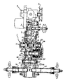
図2と図3において、1はコンバイン等の作業車の走行装置のミッションケースであり、上部位置に走行速度を変速する走行用油圧式主変速装置(ハイドロスタチックトランスミッション)2を設けている。 2 and 3, reference numeral 1 denotes a transmission case of a traveling device for a work vehicle such as a combine, and a traveling hydraulic main transmission (hydrostatic transmission) 2 for shifting traveling speed is provided at an upper position.
3はエンジンからの回転を走行用油圧式主変速装置2に入力する入力プーリ、4は走行用油圧式主変速装置2の出力軸であるが、ミッションケース1の入力軸となる。5は副変速軸であり、副変速軸5には一体的に回転するように歯車群6を設け、歯車群6にはカウンタ軸7の歯車群8を選択的に噛み合わせて変速する。カウンタ軸7から歯車伝動で回転する中間軸9にはセンターギヤ10を設け、センターギヤ10はサイドクラッチ軸11に固定の受動歯車12と常時噛合っている。
サイドクラッチ軸11には左右サイドクラッチ歯車13を摺動自在に設け、このサイドクラッチ歯車13に設けたクラッチ爪を受動歯車12の内歯に継脱自在に嵌合させて、左右サイドクラッチ15を形成する。左右サイドクラッチ15の構成は任意であり、図示の実施例には限定されない。
The left and right
サイドクラッチ歯車13は左右車軸16に設けた車軸歯車17に夫々噛み合わせて、車軸16に回転を伝達する。
しかして、サイドクラッチ軸11の近傍には差動機構20を設け、差動機構20はその左右差動出力軸21に相互の回転数を変更して出力する。差動機構20は、ミッションケース1内に回転自在にケース22を設け、ケース22内には前記左右差動出力軸21の夫々の先端を臨ませる。実施例の左右差動出力軸21は軸筒形状に形成し、左右差動出力軸21はミッションケース1に設けた取付軸21aに夫々独立して回転するように嵌合させる。この左右差動出力軸21の先端には左右傘歯車23を相対峙するように設ける。左右傘歯車23も実施例では左右差動出力軸21の先端に一体に設け、取付軸21aに遊嵌させている。
The
Accordingly, the
左右傘歯車23にはそれぞれケース22に固定の軸24に回転自在に取付けた中間傘歯車25を噛合わせ、前記ケース22の外周にはケース回転受動歯車26を設け、左右差動出力軸21の夫々に設けた旋回伝達歯車35を車軸歯車17に夫々噛み合わせる。
The left and
差動機構20は、ケース回転受動歯車26を介してケース22の回転を変更し、左右差動出力軸21の夫々に設けた旋回伝達歯車35の回転を変更することにより旋回内側となる車軸を旋回外側の車軸より遅く駆動回転させて行なう緩旋回と、旋回内側となる車軸を停止させて行なうブレーキターンと、旋回内側となる車軸を旋回外側の車軸と反対に駆動回転させて行なうスピンターンとを行う。
The
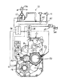
しかして、差動機構20の近傍には、前記ケース回転受動歯車26に回転を伝達する旋回用伝達装置30を設ける。31はケース回転受動歯車26に常時噛合うケース回転歯車であり、旋回用中間軸32に設ける。旋回用中間軸32には内側ボス33を回転のみ自在に嵌合させ、内側ボス33には直進用入力歯車34を一体回転するように設ける。直進用入力歯車34は前記センターギヤ10と常時噛合っている受動歯車12に常時噛合せる。
Thus, in the vicinity of the
また、前記旋回用中間軸32の外周にはケーシング37を一体回転するように設け、ケーシング37の内周にはディスクを設け、該ディスクは前記内側ボス33の外周に設けたディスクと継脱自在に当接するようにして直進用油圧クラッチ38を構成する。
In addition, a casing 37 is provided on the outer periphery of the turning
直進用油圧クラッチ38が入りになると、前記センターギヤ10の回転を直進用入力歯車34から内側ボス33を介してケーシング37に伝達し、ケーシング37が旋回用中間軸32を回転させてケース回転歯車31を回転させる。
When the rectilinear
差動機構20は、直進用油圧クラッチ38が入りのとき、差動機構20から伝達する回転が左右サイドクラッチ15から伝達される回転と同じにしてメカロックしないように、左右差動出力軸21、21の夫々が同じ回転数になるようにケース22を回転させて直進用に作動させ、同一回転している左右傘歯車23の回転を旋回伝達歯車35を介して左右車軸16に伝達させて直進する。
The
前記ケーシング37の外周にはドラム40を設け、ドラム40の基部側にはピストン41を設け、ピストン41とミッションケース1の間に外側シリンダ室42を形成する。
ドラム40には内側プレート43を設け、送油口44から外側シリンダ室42に送油されると、ピストン41とドラム40と内側プレート43が図3の矢印方向に移動してケーシング37のディスクを内側ボス33の外周のディスクから離脱させて、直進用油圧クラッチ38を切りにする。
A drum 40 is provided on the outer periphery of the casing 37, a piston 41 is provided on the base side of the drum 40, and an
The drum 40 is provided with an
内側プレート43のケース回転歯車31側には外側プレート45を設け、前記内側プレート43と外側プレート45の間に直進用油圧クラッチ38を入り方向に付勢するスプリング46を設け、スプリング46により直進用油圧クラッチ38を常時入りにする。
An outer plate 45 is provided on the
前記内側ボス33の外周には外側ボス48を回転のみ自在に設け、外側ボス48の外周に設けたディスクにケーシング37の内周に設けたディスクを、継脱自在に当接するようにして旋回用油圧クラッチ50を構成する。外側ボス48には旋回用入力歯車51を設け、旋回用入力歯車51には旋回用中間歯車51aを噛み合わせる。旋回用入力歯車51と旋回用中間歯車51aとは、サイドクラッチ15から車軸16に伝達する回転に対して所定の旋回半径となる回転を伝達しうるギヤ比に設定する(旋回用油圧クラッチ50が完全に入り状態のとき前記差動機構20がスピンターン用の出力可能に設定)。
An
旋回用油圧クラッチ50は、外側シリンダ室42に送油して直進用油圧クラッチ38を切りにすると、入りとなって、旋回用中間歯車51a→旋回用入力歯車51→外側ボス48→ディスク→ケーシング37→旋回用中間軸32を介してケース回転歯車31に伝達し、差動機構20を旋回用に作動させる。
When the hydraulic clutch 50 for turning is fed to the
即ち、直進用油圧クラッチ38と旋回用油圧クラッチ50は何れか一方が切りになると何れか他方が入りになるようにケーシング37に、夫々のディスクの移動方向に並設し、直進用油圧クラッチ38のディスクの移動方向切り側に外側シリンダ室42を設け、直進用油圧クラッチ38のディスクの移動方向入り側にスプリング46を設け、外側シリンダ室42に送油すると、ピストン41がドラム40と内側プレート43を移動させ、ケーシング37のディスクが内側ボス33の外周のディスクから離脱して、直進用油圧クラッチ38を切りにし、ケーシング37の移動により外側プレート45が移動して旋回用油圧クラッチ50を入りにする。
In other words, the linear hydraulic clutch 38 and the turning hydraulic clutch 50 are arranged in parallel in the moving direction of the respective discs in the casing 37 so that either one of the linear hydraulic clutch 38 and the rotary hydraulic clutch 50 is engaged when the other is engaged. The
この場合、旋回用油圧クラッチ50は、ディスクの接触圧力を変更し、回転伝達「0」の切り状態(直進用油圧クラッチ38が入りで接触圧力が「0」)から入り状態へ無段階に伝達するようにし、これにより、前記差動機構20のケース22の回転を、前記したように、緩旋回と、ブレーキターンと、スピンターンとをできるように変速する。
In this case, the swing hydraulic clutch 50 changes the contact pressure of the disk and continuously transmits the rotation transmission “0” from the cut-off state (the straight-travel hydraulic clutch 38 is engaged and the contact pressure is “0”) to the engaged state. As a result, the rotation of the case 22 of the
したがって、旋回用伝達装置30には、差動機構20を旋回用に作動させるための回転の伝達を継脱させる旋回用油圧クラッチ50と、差動機構20を直進用に作動させるために回転伝達を継脱させる直進用油圧クラッチ38とを設けている。
Therefore, the turning transmission device 30 includes a turning hydraulic clutch 50 for transferring transmission of rotation for operating the
なお、実施例では、ブレーキターンは、作動機構20により旋回内側の車軸16の回転を停止させて行い、走行の制動は後述する走行速度を変更操作する主変速レバーにより行う。また、別途駐車ブレーキペダルを設けてもよい。
In the embodiment, the brake turn is performed by stopping the rotation of the
図4の如く、機体の操縦部55には操向レバー(パワステレバー)56を設け、該操向レバー56の近傍には操向レバー56の操作位置を検出する操向ポテンショメータ57を設け、操向ポテンショメータ57により検出した操向レバー56の操作位置に応じて前記旋回用伝達装置30の直進用油圧クラッチ38と旋回用油圧クラッチ50の外側シリンダ室42に供給する接続圧力を昇降制御し、これにより差動機構20が左右車軸16の何れかに伝達する回転を制御するように構成する。58はコントローラ、59は走行速度を変更操作する主変速レバー、60は主変速レバー59の主変速ポテンショメータ、61は走行用油圧式主変速装置2の変速制御に置ける走行速度の変速ラインを変更操作する副変速レバー、62は副変速レバー61の副変速ポテンショメータ、63は左右車軸16、16の回転を検出する車軸回転センサ、67は油温度センサ、64は油タンク、65は送油ポンプ、66は圧力制御弁である。
As shown in FIG. 4, a steering lever (power steering lever) 56 is provided in the
図5は、走行装置の自動制御にかかる制御ブロック図である。
まず、コントローラ58に入力するデータ信号は、操向ポテンショメータ57から操向レバー56の左右傾動信号と、主変速ポテンショメータ60から主変速レバー59の変速位置信号と、副変速ポテンショメータ62から副変速レバー61の変速位置信号と、車軸回転センサ63から車軸16の回転速度と、油温度センサ67からミッションオイルの温度と、複数の籾センサ84からの籾検出信号と、ダイヤルスイッチ等の手動作動圧調整手段85と、湿田と乾田との切換スイッチ等の作業地設定手段86である。
FIG. 5 is a control block diagram according to automatic control of the traveling device.
First, the data signal input to the
複数の籾センサ84は、グレンタンク79内の所定深さごとに設ける籾を検出するセンサで、穀粒の溜まり具合を検出する。作業地設定手段86は、脱穀装置76の籾・麦切換スイッチであっても良い。
The plurality of
コントローラ58から出力する制御信号は、外側シリンダ室42へ供給するオイルを制御するクラッチ制御弁47への制御信号と、左右サイドクラッチ15を入・切するパワステソレノイド68の作動信号と、機体の後進時に鳴動するバックブザー69への鳴動信号と、エンジン回転を停止するエンジン停止ソレノイド81への停止信号である。
The control signal output from the
前記旋回用油圧クラッチ50の昇降制御は、操向レバー56による操作を操向ポテンショメータ57で検出すると、この操作角度に応じた旋回半径となるように予め設定されている接続圧にクラッチ制御弁47を制御して旋回用油圧クラッチ50を昇圧し、所定時間経過後、車軸回転センサ63により実際の回転数を検出し、この実際の回転数をコントローラ58にフィードバックし、左右の車軸16が所定の旋回半径で旋回するように、旋回用油圧クラッチ50を昇降制御する。
In the raising / lowering control of the turning hydraulic clutch 50, when the operation by the steering lever 56 is detected by the steering
また、複数の籾センサ84の籾検出信号で、クラッチ制御弁47を制御して旋回用油圧クラッチ50を段階的に昇圧或いは減圧して、収穫の進行に伴って重くなるグレンタンク79側と脱穀装置76側の旋回角度を同一になるように調整する。
In addition, the
手動作動圧調整手段85は、旋回用油圧クラッチ50の段階的昇圧或いは減圧の程度を増減調整する。作業地設定手段86では、滑り易い湿田で旋回用油圧クラッチ50の作動圧を減圧し乾田では旋回用油圧クラッチ50の作動圧を昇圧するように制御する。 The manual operating pressure adjusting means 85 adjusts the degree of stepwise pressure increase or decrease of the turning hydraulic clutch 50 to increase or decrease. The work place setting means 86 performs control such that the operating pressure of the turning hydraulic clutch 50 is reduced in a slippery wet paddy field and the operating pressure of the turning hydraulic clutch 50 is increased in a dry paddy field.
油温度センサ67が検出するミッションオイルの温度が低い場合には、旋回用油圧クラッチ50の作動圧を上昇して旋回外側の車軸16の回転を速くして旋回角が大きくならないようにする。この際の旋回用油圧クラッチ50の作動圧を手動作動圧調整手段85で変更可能にする。なお、手動作動圧調整手段85で頻繁に作動圧を調整する場合は、その調整圧を基準圧として記憶し、調整の頻度を少なくすると良い。
When the temperature of the mission oil detected by the
1 ミッションケース
15 サイドクラッチ
16 車軸
20 差動機構
38 直進用クラッチ
50 旋回用クラッチ
67 油温度センサ
85 手動作動圧調整手段
86 作業地設定手段
DESCRIPTION OF SYMBOLS 1 Transmission case 15 Side clutch 16
Claims (2)
Priority Applications (1)
| Application Number | Priority Date | Filing Date | Title |
|---|---|---|---|
| JP2014219487A JP2016084083A (en) | 2014-10-28 | 2014-10-28 | Working vehicle |
Applications Claiming Priority (1)
| Application Number | Priority Date | Filing Date | Title |
|---|---|---|---|
| JP2014219487A JP2016084083A (en) | 2014-10-28 | 2014-10-28 | Working vehicle |
Publications (1)
| Publication Number | Publication Date |
|---|---|
| JP2016084083A true JP2016084083A (en) | 2016-05-19 |
Family
ID=55972187
Family Applications (1)
| Application Number | Title | Priority Date | Filing Date |
|---|---|---|---|
| JP2014219487A Pending JP2016084083A (en) | 2014-10-28 | 2014-10-28 | Working vehicle |
Country Status (1)
| Country | Link |
|---|---|
| JP (1) | JP2016084083A (en) |
Cited By (2)
| Publication number | Priority date | Publication date | Assignee | Title |
|---|---|---|---|---|
| CN106438761A (en) * | 2016-10-24 | 2017-02-22 | 广州汽车集团股份有限公司 | Method and device for determining temperature of wet dual clutch transmission |
| CN106678213A (en) * | 2016-11-10 | 2017-05-17 | 广州汽车集团股份有限公司 | Temperature real-time monitoring method and device for wet double clutch transmission |
-
2014
- 2014-10-28 JP JP2014219487A patent/JP2016084083A/en active Pending
Cited By (4)
| Publication number | Priority date | Publication date | Assignee | Title |
|---|---|---|---|---|
| CN106438761A (en) * | 2016-10-24 | 2017-02-22 | 广州汽车集团股份有限公司 | Method and device for determining temperature of wet dual clutch transmission |
| CN106438761B (en) * | 2016-10-24 | 2019-07-09 | 广州汽车集团股份有限公司 | Method and apparatus for determining wet dual clutch transmission temperature |
| CN106678213A (en) * | 2016-11-10 | 2017-05-17 | 广州汽车集团股份有限公司 | Temperature real-time monitoring method and device for wet double clutch transmission |
| CN106678213B (en) * | 2016-11-10 | 2019-08-02 | 广州汽车集团股份有限公司 | Temperature method of real-time and device for wet dual clutch transmission |
Similar Documents
| Publication | Publication Date | Title |
|---|---|---|
| JP2016084083A (en) | Working vehicle | |
| CN102077729B (en) | Combine harvester | |
| JP4430181B2 (en) | Crawler work vehicle | |
| JP2011110020A5 (en) | ||
| JP2009261304A (en) | Device for controlling hydraulic pressure for lifting and lowering reaping device in combine harvester | |
| JP4915927B2 (en) | Combine | |
| JP5618568B2 (en) | Sensor structure for shift lever | |
| JP2007008321A (en) | Turning device for combine | |
| JP2004217071A (en) | Turning control device for traveling vehicle | |
| JP4214769B2 (en) | Combine | |
| JP2007008321A5 (en) | ||
| JP4112738B2 (en) | Mobile farm machine | |
| JP2017042132A (en) | Combine-harvester | |
| JP3498715B2 (en) | Traveling gear for mobile agricultural machines | |
| JP2008306972A (en) | Combine harvester | |
| JP3498710B2 (en) | Traveling gear for mobile agricultural machines | |
| JP4189144B2 (en) | Brake device for tractor | |
| JP4292338B2 (en) | Combine | |
| JP4529985B2 (en) | Combine | |
| JP2007062543A (en) | Running driving device for working machine | |
| JP6598557B2 (en) | Work vehicle | |
| JP4529986B2 (en) | Combine | |
| JP3498709B2 (en) | Traveling gear for mobile agricultural machines | |
| JP3763270B2 (en) | Traveling device | |
| JP5225127B2 (en) | Combine |