JP2016054712A5 - - Google Patents

Download PDF

Info

Publication number
JP2016054712A5
JP2016054712A5 JP2014185464A JP2014185464A JP2016054712A5 JP 2016054712 A5 JP2016054712 A5 JP 2016054712A5 JP 2014185464 A JP2014185464 A JP 2014185464A JP 2014185464 A JP2014185464 A JP 2014185464A JP 2016054712 A5 JP2016054712 A5 JP 2016054712A5
Authority
JP
Japan
Prior art keywords
bail
peripheral surface
movement
shaft
cover portion
Prior art date
Legal status (The legal status is an assumption and is not a legal conclusion. Google has not performed a legal analysis and makes no representation as to the accuracy of the status listed.)
Granted
Application number
JP2014185464A
Other languages
Japanese (ja)
Other versions
JP6345555B2 (en
JP2016054712A (en
Filing date
Publication date
Application filed filed Critical
Priority claimed from JP2014185464A external-priority patent/JP6345555B2/en
Priority to JP2014185464A priority Critical patent/JP6345555B2/en
Priority to KR1020150071038A priority patent/KR102392180B1/en
Priority to TW104119300A priority patent/TWI664900B/en
Priority to US14/833,545 priority patent/US9642347B2/en
Priority to CN201510566082.0A priority patent/CN105409897B/en
Priority to EP15184534.4A priority patent/EP2995198B1/en
Publication of JP2016054712A publication Critical patent/JP2016054712A/en
Publication of JP2016054712A5 publication Critical patent/JP2016054712A5/ja
Publication of JP6345555B2 publication Critical patent/JP6345555B2/en
Application granted granted Critical
Active legal-status Critical Current
Anticipated expiration legal-status Critical

Links

Images

Description

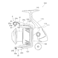
図1及び図2に示すように、第2ベール支持部材22は、第1端部22aと第2端部22bとを有する。第1端部22aは、第2ロータアーム123に揺動可能に装着される。第2端部22bは、ベール23の第2端部23bを支持する。 As shown in FIGS. 1 and 2, the second bail support member 22 has a first end 22a and a second end 22b . The first end 22a is swingably attached to the second rotor arm 123. The second end 22 b supports the second end 23 b of the bail 23.

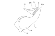
図3に示すように、ベール23は、略U字状のステンレス合金製の部材である。ベール23は、スプール130の外周面に沿って外方に凸となるように湾曲している。このベール23は、第1端部23aにカバー部23を有している。 As shown in FIG. 3, the bail 23 is a substantially U-shaped stainless alloy member. The bail 23 is curved so as to protrude outward along the outer peripheral surface of the spool 130. The bail 23 includes a cover portion 23 c to the first end portion 23a.

このカバー部23は、支持軸24を介して、第1ベール支持部材21に支持されている。また、ベール23の第2端部23bは、第2ベール支持部材22に支持されている。釣糸案内機構2が糸開放姿勢から糸案内姿勢に復帰したときに、ベール23は、釣り糸をカバー部23を介してラインローラ3に導く。 The cover portion 23 c is supported by the first bail support member 21 via the support shaft 24. The second end 23 b of the bail 23 is supported by the second bail support member 22. When fishing line guide mechanism 2 is returned to the yarn guide posture from the line-releasing posture, the bail 23, the fishing line via the cover portion 23 c directs the line roller 3.

支持軸24は、第1ベール支持部材21とベール23のカバー部23との間を延びる。支持軸24は、筒状部241とボルト部242とを含む。筒状部241は、軸部241aと頭部241bとを有している。軸部241aは、円筒状であって、内周面に雌ネジ部が形成されている。頭部241bは、軸部241aよりも径が大きい。この頭部241bがカバー部23と当接することによって、筒状部241の軸方向の移動が規制される。 The support shaft 24 extends between the first bail support member 21 and the cover portion 23 c of the bail 23. The support shaft 24 includes a cylindrical portion 241 and a bolt portion 242. The cylindrical part 241 has a shaft part 241a and a head part 241b. The shaft portion 241a has a cylindrical shape, and an internal thread portion is formed on the inner peripheral surface. The head portion 241b has a larger diameter than the shaft portion 241a. By the head 241b is brought into contact with the cover portion 23 c, the axial movement of the tubular portion 241 is restricted.

第1及び第2規制部材7,8は、ベアリング部材4の軸方向の移動を規制する。詳細には、第1規制部材7は、軸方向において、ベール23のカバー部23とベアリング部材4との間に配置される。このため、第1規制部材7は、ベアリング部材4のカバー部23側への移動(図6の左側への移動)を規制する。また、第2規制部材8は、軸方向において、第1ベール支持部材21の第2端部21bとベアリング部材4との間に配置される。このため、第2規制部材8は、ベアリング部材4の第1ベール支持部材21側への移動(図6の右側への移動)を規制する。 The first and second regulating members 7 and 8 regulate the movement of the bearing member 4 in the axial direction. Specifically, the first restricting member 7 is disposed between the cover portion 23 c of the bail 23 and the bearing member 4 in the axial direction. Therefore, the first regulating member 7 regulates the movement of the cover portion 23 c side of the bearing member 4 (movement to the left in FIG. 6). The second restricting member 8 is disposed between the second end portion 21 b of the first bail support member 21 and the bearing member 4 in the axial direction. Therefore, the second restriction member 8 restricts the movement of the bearing member 4 toward the first bail support member 21 (movement to the right side in FIG. 6).

第1シール部51cは、径方向において、第1規制部材7と間隔をあけて配置されている。すなわち、第1シール部51cの内径は、第1規制部材7の外径よりも大きい。このため、第1保持部材51が回転軸O周りに回転するとき、第1シール部51cは第1規制部材7とは実質的に接触しない。第1シール部51cの内周面は、第1規制部材7の外周面と対向している。 The first seal portion 51c is disposed at a distance from the first restricting member 7 in the radial direction. That is, the inner diameter of the first seal portion 51 c is larger than the outer diameter of the first restricting member 7. For this reason, when the 1st holding member 51 rotates around the rotating shaft O , the 1st seal | sticker part 51c does not contact the 1st control member 7 substantially. The inner peripheral surface of the first seal portion 51 c faces the outer peripheral surface of the first restricting member 7.

第2シール部52cは、径方向において、第2規制部材8と間隔をあけて配置されている。すなわち、第2シール部52cの内径は、第2規制部材8の外径よりも大きい。このため、第2保持部材52が回転軸O周りに回転するとき、第2シール部52cは第2規制部材8とは実質的に接触しない。第2シール部52cの内周面は、第2規制部材8の外周面と対向している。 The second seal portion 52c is disposed at a distance from the second restricting member 8 in the radial direction. That is, the inner diameter of the second seal portion 52 c is larger than the outer diameter of the second restricting member 8. For this reason, when the second holding member 52 rotates around the rotation axis O , the second seal portion 52c does not substantially contact the second regulating member 8. The inner peripheral surface of the second seal portion 52 c faces the outer peripheral surface of the second restricting member 8.

JP2014185464A 2014-09-11 2014-09-11 Line roller Active JP6345555B2 (en)

Priority Applications (6)

Application Number Priority Date Filing Date Title
JP2014185464A JP6345555B2 (en) 2014-09-11 2014-09-11 Line roller
KR1020150071038A KR102392180B1 (en) 2014-09-11 2015-05-21 Line Roller
TW104119300A TWI664900B (en) 2014-09-11 2015-06-15 Fishing line roller
US14/833,545 US9642347B2 (en) 2014-09-11 2015-08-24 Line roller
CN201510566082.0A CN105409897B (en) 2014-09-11 2015-09-08 Fishing line roller
EP15184534.4A EP2995198B1 (en) 2014-09-11 2015-09-09 Line roller

Applications Claiming Priority (1)

Application Number Priority Date Filing Date Title
JP2014185464A JP6345555B2 (en) 2014-09-11 2014-09-11 Line roller

Publications (3)

Publication Number Publication Date
JP2016054712A JP2016054712A (en) 2016-04-21
JP2016054712A5 true JP2016054712A5 (en) 2017-08-31
JP6345555B2 JP6345555B2 (en) 2018-06-20

Family

ID=54105685

Family Applications (1)

Application Number Title Priority Date Filing Date
JP2014185464A Active JP6345555B2 (en) 2014-09-11 2014-09-11 Line roller

Country Status (6)

Country Link
US (1) US9642347B2 (en)
EP (1) EP2995198B1 (en)
JP (1) JP6345555B2 (en)
KR (1) KR102392180B1 (en)
CN (1) CN105409897B (en)
TW (1) TWI664900B (en)

Families Citing this family (3)

* Cited by examiner, † Cited by third party
Publication number Priority date Publication date Assignee Title
US9210920B1 (en) 2013-07-03 2015-12-15 W.C. Bradley/Zebco Holdings, Inc. Fishing reel with improved line management and control system and clicker mechanism
JP6058239B1 (en) * 2015-10-21 2017-01-18 ピュア・フィッシング・ジャパン株式会社 Fishing reel
JP7158271B2 (en) * 2018-12-21 2022-10-21 株式会社シマノ line roller

Family Cites Families (21)

* Cited by examiner, † Cited by third party
Publication number Priority date Publication date Assignee Title
JP2530818Y2 (en) * 1990-11-20 1997-04-02 株式会社シマノ Spinning reel line roller
JP2550173Y2 (en) * 1992-09-17 1997-10-08 ダイワ精工株式会社 Fishing line guide roller
AU700270B2 (en) 1994-10-31 1998-12-24 Daiwa Seiko Inc. Fishline guide arrangement for spinning reel
JPH09238600A (en) * 1996-03-08 1997-09-16 Shimano Inc Fishline guiding mechanism for spinning reel
JP3287389B2 (en) 1997-01-31 2002-06-04 ダイワ精工株式会社 Spinning reel for fishing
JP3509519B2 (en) * 1997-11-14 2004-03-22 株式会社シマノ Fishing line guide mechanism for spinning reel
JP2000102334A (en) * 1998-07-27 2000-04-11 Daiwa Seiko Inc Spinning reel for fishing
JP3926044B2 (en) * 1998-08-24 2007-06-06 株式会社シマノ Fishing reel guide mechanism for spinning reel
US6227474B1 (en) 1998-08-27 2001-05-08 Kabushiki Kaisha Johshuya Spinning reel with tension roller for preventing fishing line twist
US6336604B1 (en) * 1998-11-12 2002-01-08 Shimano Inc. Fishing line guide mechanism for a spinning reel
JP4056217B2 (en) * 2000-12-26 2008-03-05 ダイワ精工株式会社 Fishing spinning reel
JP2004121166A (en) * 2002-10-07 2004-04-22 Shimano Inc Fishline guiding mechanism of spinning reel
JP2006000101A (en) 2004-06-15 2006-01-05 Yasuhiko Nakajima Insect catcher
JP4451743B2 (en) * 2004-08-09 2010-04-14 株式会社シマノ Fishing reel guide mechanism for spinning reel
JP4555653B2 (en) * 2004-09-30 2010-10-06 グローブライド株式会社 Fishing spinning reel
US7665683B2 (en) * 2007-12-18 2010-02-23 Shimano Inc. Fishing line guiding mechanism of spinning reel
US7967232B2 (en) * 2009-10-28 2011-06-28 Shimano Inc. Spinning-reel fishing line guide mechanism
JP5481228B2 (en) * 2010-02-26 2014-04-23 株式会社シマノ Fishing reel guide mechanism for spinning reel
KR101930538B1 (en) * 2010-08-27 2018-12-18 글로브라이드 가부시키가이샤 Reel for fishing
JP2013202006A (en) * 2012-03-29 2013-10-07 Shimano Inc Fishing line guide mechanism of spinning reel and the spinning reel
JP5931765B2 (en) * 2013-01-31 2016-06-08 グローブライド株式会社 Fishing spinning reel

Similar Documents

Publication Publication Date Title
SG163480A1 (en) Traverse camshaft for fishing reel and reciprocal movement mechanism for fishing reel employing the traverse camshaft
JP2016054712A5 (en)
US8561930B2 (en) Spinning reel fishing line guide mechanism
JP6560930B2 (en) Line roller unit and fishing line guide mechanism
JP2015065840A5 (en)
JP6345555B2 (en) Line roller
JP6261973B2 (en) Spinning reel
JP2014223054A (en) Line roller and fishing line guide mechanism using the same
JP5956799B2 (en) Double-bearing reel and drag operation member for double-bearing reel
US20150250156A1 (en) Bail support mechanism for a spinning reel
KR102638045B1 (en) Bearing holding structure for fishing reel, and fishing reel
JP6845695B2 (en) Double bearing reel
JP6261971B2 (en) Spinning reel
JP6636236B2 (en) Handle cap
JP6261972B2 (en) Spinning reel
JP6392602B2 (en) Spinning reel
JP6315688B2 (en) Fishing reel
JP5931765B2 (en) Fishing spinning reel
JP6769722B2 (en) Double bearing reel
JP6405081B2 (en) Line roller and fishing line guide mechanism using the same
TWM487851U (en) Clutch stroke adjusting device of bicycle hub and bicycle hub using the same
JP6247138B2 (en) Fishing spinning reel
JP2013230354A5 (en)
JP2015192624A (en) spinning reel for fishing
CN104170803A (en) Spinning fishing reel