JP2016050737A - Heating cooker - Google Patents
Heating cooker Download PDFInfo
- Publication number
- JP2016050737A JP2016050737A JP2014177261A JP2014177261A JP2016050737A JP 2016050737 A JP2016050737 A JP 2016050737A JP 2014177261 A JP2014177261 A JP 2014177261A JP 2014177261 A JP2014177261 A JP 2014177261A JP 2016050737 A JP2016050737 A JP 2016050737A
- Authority
- JP
- Japan
- Prior art keywords
- heating chamber
- heater
- top wall
- storage body
- wall
- Prior art date
- Legal status (The legal status is an assumption and is not a legal conclusion. Google has not performed a legal analysis and makes no representation as to the accuracy of the status listed.)
- Pending
Links
Images
Landscapes
- Electric Ovens (AREA)
Abstract
Description
本発明は、電子レンジ機能を有する引き出し式の加熱調理器に関する。 The present invention relates to a drawer-type heating cooker having a microwave function.
従来、引き出し式の加熱調理器が提案されている(特許文献1〜4参照)。
引き出し式の加熱調理器は、加熱室を有する調理器本体と、電磁波発生部と、電磁波発生部が発した電磁波を加熱室の内部へ導くための導波管とを備える。
電磁波発生部は加熱室の背後に配されており、導波管は電磁波発生部から加熱室の上方に亘って設けられている。
Conventionally, a drawer-type heating cooker has been proposed (see
The drawer-type heating cooker includes a cooker body having a heating chamber, an electromagnetic wave generator, and a waveguide for guiding electromagnetic waves generated by the electromagnetic wave generator to the inside of the heating chamber.
The electromagnetic wave generation unit is disposed behind the heating chamber, and the waveguide is provided from the electromagnetic wave generation unit to above the heating chamber.
更に、引き出し式の加熱調理器は、被調理物が収納される収納体を備える。収納体は、加熱室の左右両側方に配された2本の両側スライドレールと、加熱室の下方に配された1本の下側スライドレールとによって、加熱室の内部に対して出没可能に支持されている。
下側スライドレールにはラックギアが取り付けられている。ラックギアに噛み合うピニオンギアをモータが回転駆動することによって、収納体が加熱室の内部から引き出されたり加熱室の内部へ押し入れられたり(即ち出没)する。モータ及びピニオンギアは、加熱室の底壁の下方に配されている。
Furthermore, the drawer-type heating cooker is provided with a storage body in which an object to be cooked is stored. The storage body can be moved in and out of the inside of the heating chamber by two slide rails arranged on both sides of the heating chamber and one lower slide rail arranged below the heating chamber. It is supported.
A rack gear is attached to the lower slide rail. When the motor rotates the pinion gear that meshes with the rack gear, the storage body is pulled out from the inside of the heating chamber or pushed into the inside of the heating chamber (ie, appears and disappears). The motor and the pinion gear are arranged below the bottom wall of the heating chamber.
ところで、引き出し式ではない一般的な加熱調理器は、可動ヒータを備えていることがある(特許文献5,6参照)。可動ヒータは、モータに駆動されて自動的に揺動するか、又は使用者が手動で揺動させる。可動ヒータは、被調理物に対して接離したり、被調理物の表面に沿って周回したりすることによって、被調理物を適切に加熱する。 By the way, the general cooking-by-heating machine which is not a drawer type may be provided with the movable heater (refer patent documents 5 and 6). The movable heater is automatically swung by being driven by a motor, or manually swung by a user. A movable heater heats a to-be-cooked object appropriately by contacting / separating with a to-be-cooked object, or circulating around the surface of a to-be-cooked object.
特許文献1〜4に記載された加熱調理器のように、従来の引き出し式の加熱調理器は、電子レンジ機能のみを有する単機能型である。
従来の引き出し式の加熱調理器にヒータを追加すれば、特許文献5,6に記載された加熱調理器のような電子レンジ機能及びグリル機能等を有する多機能型の加熱調理器が得られる。このために、加熱調理器は、加熱室の内部の天壁側に配されたヒータから、ヒータの下方に位置する被調理物側へ熱が伝達するよう構成される。
Like the heating cookers described in
If a heater is added to the conventional drawer-type cooking device, a multifunctional cooking device having a microwave function, a grill function, and the like like the cooking device described in Patent Documents 5 and 6 can be obtained. For this purpose, the heating cooker is configured to transfer heat from a heater arranged on the top wall side inside the heating chamber to the cooked food side located below the heater.
この場合、ヒータが発した熱は加熱室の上方及び下方にも伝達する。故に、加熱室の下方に配されている下側スライドレール、ラックギア、ピニオンギア、及びモータが高温になり易い。
ところが、ラックギア、ピニオンギア、及びモータは、一般に耐熱性が低い。かといって、これらを全て高耐熱性のものにすると、加熱調理器の製造コストが増大する。
In this case, the heat generated by the heater is also transmitted above and below the heating chamber. Therefore, the lower slide rail, the rack gear, the pinion gear, and the motor arranged below the heating chamber are likely to be hot.
However, rack gears, pinion gears, and motors generally have low heat resistance. However, if these are all made of high heat resistance, the manufacturing cost of the cooking device increases.
本発明は斯かる事情に鑑みてなされたものであり、その主たる目的は、電子レンジ機能を含む多機能型であって、安価に製造可能な引き出し式の加熱調理器を提供することにある。 This invention is made | formed in view of such a situation, The main objective is to provide the drawer-type heating cooker which is a multifunctional type containing a microwave oven function, and can be manufactured cheaply.
本発明に係る加熱調理器は、正面側に開口部が設けられた加熱室を有する調理器本体と、前記加熱室の内部に対して前記開口部を通して出没可能に支持され、被調理物が収納される収納体と、該収納体を出没させるためのアクチュエータと、電磁波発生部と、該電磁波発生部が発した電磁波を前記加熱室の内部へ導くための導波管とを備え、前記アクチュエータ、前記電磁波発生部、及び前記導波管は、前記加熱室の外部に配されている加熱調理器において、前記加熱室の内部の天壁側又は底壁側に配されるヒータを備え、前記アクチュエータは、前記加熱室の天壁及び底壁の何れかに対向する高温領域以外の低温領域に配されていることを特徴とする。 A cooking device according to the present invention is a cooker body having a heating chamber provided with an opening on the front side, and is supported so as to be able to appear and retract through the opening with respect to the inside of the heating chamber. A storage body, an actuator for retracting the storage body, an electromagnetic wave generation unit, and a waveguide for guiding the electromagnetic wave generated by the electromagnetic wave generation unit to the inside of the heating chamber, the actuator, The electromagnetic wave generation unit and the waveguide include a heater arranged on a top wall side or a bottom wall side inside the heating chamber in a heating cooker arranged outside the heating chamber, and the actuator Is arranged in a low temperature region other than the high temperature region facing either the top wall or the bottom wall of the heating chamber.
本発明に係る加熱調理器は、前記ヒータは、前記加熱室の内部の天壁側に配されており、前記電磁波発生部は、前記加熱室の後壁又は側壁に対向する前記低温領域に配され、前記導波管は、前記加熱室の後壁又は側壁に対向する前記低温領域か、或いは前記底壁に対向する前記高温領域に配されていることを特徴とする。 In the heating cooker according to the present invention, the heater is disposed on the top wall side inside the heating chamber, and the electromagnetic wave generator is disposed in the low temperature region facing the rear wall or side wall of the heating chamber. The waveguide is arranged in the low temperature region facing the rear wall or side wall of the heating chamber or in the high temperature region facing the bottom wall.
本発明に係る加熱調理器は、前記ヒータは、前記加熱室の内部の天壁側と、該天壁側より低い前記被調理物の収納位置側との間で揺動可能に支持してあり、前記収納体の出/没に連動して前記ヒータを前記天壁側/前記収納位置側に揺動させる揺動機構を備えることを特徴とする。 In the heating cooker according to the present invention, the heater is supported so as to be swingable between a top wall side inside the heating chamber and a storage position side of the cooking object lower than the top wall side. And a swing mechanism that swings the heater toward the top wall side / the storage position side in conjunction with the exit / retraction of the storage body.
本発明に係る加熱調理器は、前記収納体は、前記開口部を開閉する扉を一体的に有し、前記揺動機構は、前記ヒータと共に揺動する揺動部と、前記ヒータに対し、該ヒータが前記天壁側に揺動する方向へ付勢する付勢部と、前記収納体の出/没に伴って前記揺動部に対し離隔/接近し、前記扉が閉じるときに前記揺動部に接触して、前記ヒータが前記収納位置側に揺動する方向へ前記揺動部に外力を加える接離部とを有することを特徴とする。 In the cooking device according to the present invention, the storage body integrally includes a door that opens and closes the opening, and the swing mechanism is configured to swing with the heater and the heater. An urging portion for urging the heater in a direction to oscillate toward the top wall side, and the oscillating portion is separated / approached as the storage body comes in / out, and the oscillating portion is moved when the door is closed. And a contact / separation portion that contacts the moving portion and applies an external force to the swinging portion in a direction in which the heater swings toward the storage position.
本発明に係る加熱調理器は、前記ヒータは、前記加熱室の内部の天壁側に配されており、前記導波管が導いた電磁波を前記加熱室の内部へ散乱させる可動アンテナと、該可動アンテナを駆動する駆動部と、送風部と、該送風部が送風した空気を前記電磁波発生部及び駆動部夫々の側へ導くための通風路とを備え、前記可動アンテナ、駆動部、送風部、及び通風路は、前記加熱室の外部における前記加熱室の後壁又は側壁に対向する前記低温領域に配されていることを特徴とする。 In the heating cooker according to the present invention, the heater is disposed on the top wall side inside the heating chamber, and a movable antenna that scatters electromagnetic waves guided by the waveguide into the heating chamber; A drive unit that drives the movable antenna, a blower unit, and a ventilation path for guiding the air blown by the blower unit to the electromagnetic wave generation unit and the drive unit, respectively, the movable antenna, the drive unit, and the blower unit The ventilation path is arranged in the low temperature region facing the rear wall or side wall of the heating chamber outside the heating chamber.
本発明に係る加熱調理器は、前記収納体を出没可能に支持するスライドレールと、該スライドレールに取り付けられており、前記収納体と共に出没するラックギアと、該ラックギアに噛み合うピニオンギアとを、前記加熱室の外部における前記加熱室の側壁に対向する前記低温領域に更に備え、前記アクチュエータは、前記ピニオンギアを回転駆動するモータであり、前記側壁に対向する前記低温領域に配されていることを特徴とする。 The heating cooker according to the present invention includes a slide rail that supports the storage body so as to be able to appear and retract, a rack gear that is attached to the slide rail, and that appears and disappears together with the storage body, and a pinion gear that meshes with the rack gear. Further provided in the low temperature region facing the side wall of the heating chamber outside the heating chamber, the actuator is a motor that rotationally drives the pinion gear, and is disposed in the low temperature region facing the side wall. Features.
本発明の加熱調理器による場合、収納体を出没させるためのアクチュエータは、ヒータが発する熱が伝達し難い低温領域に配されている。故に、加熱調理器が備えるべきアクチュエータとして、従来同様の低耐熱性を有する安価なアクチュエータを採用することができる。この結果、電子レンジ機能を含む多機能型の引き出し式の加熱調理器を安価に製造することができる。 In the case of the heating cooker according to the present invention, the actuator for causing the storage body to appear and disappear is arranged in a low temperature region in which heat generated by the heater is difficult to transmit. Therefore, an inexpensive actuator having the same low heat resistance as the conventional one can be adopted as the actuator to be provided in the cooking device. As a result, a multi-function drawer-type cooking device including a microwave function can be manufactured at low cost.
以下、本発明を、その実施の形態を示す図面に基づいて詳述する。以下の説明では、図において矢符で示す上下、前後、及び左右を使用する。 Hereinafter, the present invention will be described in detail with reference to the drawings illustrating embodiments thereof. In the following description, up and down, front and rear, and left and right indicated by arrows in the figure are used.
実施の形態 1.
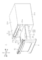
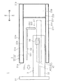
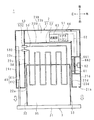
図1は、本発明の実施の形態1に係る加熱調理器1の外観構成を略示する斜視図である。
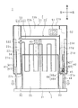
図2及び図3は、加熱調理器1の内部構成を模式的に示す平面図及び側面図である。
加熱調理器1は、システムキッチンの一部を構成している。
加熱調理器1は、調理器本体2、収納体3、スライドレール41〜43、ラックギア44、ピニオンギア45、モータ46、マグネトロン51、導波管52、及びヒータ53を備えている。
FIG. 1 is a perspective view schematically showing an external configuration of a
FIG.2 and FIG.3 is the top view and side view which show typically the internal structure of the
The
The
調理器本体2は、直方体状の筐体21と、筐体21の内部に形成された横姿勢の有底矩形筒状の加熱室22とを有する。
筐体21は、夫々金属製の各矩形状の前壁21a、後壁21b、左側壁21c、右側壁21d、天壁21e、及び底壁21fを一体的に有する。
加熱室22は、矩形状の開口部22aを有し、夫々金属製の各矩形状の後壁22b、左側壁22c、右側壁22d、天壁22e、及び底壁22fを一体的に有する。加熱室22の開口部22aは、筐体21の前壁21aの上下左右方向中央部に形成されている。右側壁22dには、図示しない導波口が設けられている。
The
The
The
筐体21の内部且つ加熱室22の外部であって、後壁22b〜右側壁22dに対向する領域を、以下では低温領域23b〜23dという。
筐体21の内部且つ加熱室22の外部であって、天壁22e及び底壁22fに対向する領域を、以下では高温領域23e,23fという。
An area inside the
The regions inside the
収納体3は、被調理物(例えば食品)を収納可能な抽斗状であり、抽斗の前板に相当する扉31、左右の端板に相当する側板部32,33、先板に相当する背板部34、及び底板に相当する底板部35を一体的に有する。
底板部35の上面は、被調理物が載置される載置面である。
The
The upper surface of the
側板部32,33、及び底板部35夫々の前後方向の長さは、加熱室22の奥行きよりも短い。背板部34及び底板部35夫々の左右方向の長さは、加熱室22の開口部22aの左右方向の長さよりも短い。側板部32〜背板部34夫々の上下方向の長さは、開口部22aの上下方向の長さよりも短い。扉31の上下左右方向の長さは、開口部22aの上下左右方向の長さよりも長い。
扉31が加熱室22の開口部22aを閉鎖した場合、側板部32,33、背板部34、及び底板部35は加熱室22に収容される。扉31によって開口部22aが閉鎖されている加熱室22からマイクロ波が漏出することはない。
The length in the front-rear direction of each of the
When the
収納体3は、スライドレール41〜43によって、加熱室22の内部に対して出没可能に支持されている。収納体3の加熱室22に対する突出方向/没入方向は前方向(図2及び図3中の白抜矢符方向)/後方向である。
スライドレール41,42は、低温領域23c,23dに配されている。スライドレール43は、加熱室22の底壁22fの内面に配されている。
スライドレール41は固定レール411及び可動レール412を有する。固定レール411は、筐体21の左側壁21cの内面に、前後方向の横姿勢で取り付けられている。可動レール412は、前後方向に摺動可能に、固定レール411の右側に取り付けられており、筐体21の前壁21aに設けられている開口部を貫通している。
The
The slide rails 41 and 42 are arranged in the
The
スライドレール42は固定レール421及び可動レール422を有する。固定レール421は、筐体21の右側壁21dの内面に、前後方向の横姿勢で取り付けられている。可動レール422は、前後方向に摺動可能に、固定レール411の左側に取り付けられており、筐体21の前壁21aに設けられている開口部を貫通している。
スライドレール41,42の可動レール412,422夫々は、前端部が収納体3の扉31に取り付けられている。
The
The front ends of the
スライドレール43は固定レール431及び可動レール432を有する。固定レール431は、加熱室22の底壁22fの内面に、前後方向の横姿勢で取り付けられている。可動レール432は、前後方向に摺動可能に、固定レール411の上側に取り付けられており、筐体21の前壁21aに設けられている図示しない開口部を貫通している。
スライドレール43の可動レール432は、収納体3の底板部35の外面に取り付けられている。
スライドレール43は加熱室22の内部に配されているので、加熱室の外部に配されているスライドレール41,42よりも耐熱性が高い素材で構成されている。例えば、スライドレール41,42は合成樹脂製であり、スライドレール43は金属製である。
The
The
Since the
ラックギア44及びピニオンギア45は合成樹脂製であり、低温領域23dに配されている。
ラックギア44は、前後方向の横姿勢で、スライドレール42の可動レール422に取り付けられている。ラックギア44の歯は下向きである。
ピニオンギア45は、前後方向の縦姿勢で、ラックギア44に下側から噛み合っている。
ただし、図2では、図を見やすくするために、ラックギア44の歯が上向きであり、ピニオンギア45がラックギア44に上側から噛み合っている状態を示している。
The
The
The
However, FIG. 2 shows a state in which the teeth of the
モータ46は、収納体3を出没させるためのアクチュエータであり、ハウジング46aから出力軸46bが右方向へ突出する姿勢で低温領域23dに配されている。ハウジング46aは、筐体21の底壁21fの内側に載置されていてもよく、加熱室22の右側壁22dの外面に取り付けられていてもよい。筐体21又は加熱室22からハウジング46aへの熱伝達を抑制すべく、図示しない断熱部が配されていてもよい。
モータ46の出力軸46bにはピニオンギア45が取り付けられている。モータ46の出力軸46bが回転すると、これに伴ってピニオンギア45が回転する。
The
A
ピニオンギア45の回転運動は、ラックギア44の前後方向の直線運動になる。このとき、スライドレール42の可動レール422が固定レール421に沿って摺動する。可動レール422の摺動は、収納体3を介してスライドレール41,43に伝わり、可動レール412,432が固定レール411,431に沿って摺動する。可動レール412〜432の固定レール411〜431に沿った摺動に伴って、収納体3は、加熱室22の内部から突出し、また、加熱室22の内部に没入する。収納体3の出没に伴い、ラックギア44は低温領域23dに対して出没する。
The rotational motion of the
スライドレール41,42は、従来の引き出し式の加熱調理器が備える2本の両側スライドレールに相当し、スライドレール43は、従来の引き出し式の加熱調理器が備える下側スライドレールに相当する。ただし、従来の引き出し式の加熱調理器においては、ラックギア44、ピニオンギア45、及びモータ46に相当するものは下側スライドレールに対して配されていたが、加熱調理器1においては、ラックギア44、ピニオンギア45、及びモータ46は、2本の両側スライドレールの一方に対して配されている。
The slide rails 41 and 42 correspond to the two side slide rails included in the conventional drawer-type heating cooker, and the
なお、スライドレール41,42の固定レール411,421は、図示しない断熱部を介して、加熱室22の左側壁22c及び右側壁22dの外面に取り付けられていてもよい。この場合、モータ46は、例えば筐体21の左側壁21cの内面に取り付けられる。
また、スライドレール41〜43に替えて、スライドレール41,42に対応する左右2本のスライドレールが収納体3を支える構成でもよい。この場合、耐熱性が高いスライドレール43を備えている必要がない。
Note that the fixed
Further, instead of the slide rails 41 to 43, the left and right two slide rails corresponding to the slide rails 41 and 42 may support the
マグネトロン51は、マイクロ波を発する電磁波発生部である。マグネトロン51は、低温領域23bに配されている。なお、マグネトロン51は、低温領域23dに配されていてもよい。
The
導波管52は、低温領域23b,23dにて、マグネトロン51から加熱室22の右側壁22dに設けられた導波口に亘って配されている。マグネトロン51が発したマイクロ波は、導波管52に導かれ、導波口を通って、加熱室22の内部に伝播する。
The
なお、導波管52は、マグネトロン51から、低温領域23bに配された図示しないアンテナ室にわたって配されていてもよい。導波管52によって、マグネトロン51からアンテナ室に導かれたマイクロ波は、アンテナ室に収容された図示しない可動アンテナによって、加熱室22の内部に散乱する。
The
ヒータ53は、適宜に屈曲された1本の金属管を用いてなるヒータ本体531と、ヒータ本体531の一端部及び他端部に取り付けられている横姿勢の筒状の非発熱部532,532とを一体的に有する。
非発熱部532,532は、加熱室22の左側壁22cを貫通して左側壁22cに支持されている。ヒータ本体531に給電する図示しない給電線は、加熱室22の外部に配されており、非発熱部532,532の内部を通してヒータ本体531に電気的に接続されている。
ヒータ本体531は、矩形の4辺の内の1辺が矩形の内側にて蛇行しているような形状である。
The
The
The
ヒータ53は、加熱室22の天壁22e近傍(少なくとも加熱室22の上下方向中央部よりも天壁22e側)に配されている。ヒータ本体531は収納体3の載置面に平行に、且つ、収納体3の載置面に載置される被調理物の高さよりも高い位置になるように配されている。
加熱室22の内部におけるヒータ53よりも天壁22e側には、ヒータ53が発した熱を下方へ反射する図示しない熱反射部が配されている。
なお、ヒータ本体531はガラス管を用いてなる構成でもよい。
The
A heat reflecting portion (not shown) that reflects the heat generated by the
The
以上のような加熱調理器1は、従来の引き出し式の加熱調理器とは異なり、マグネトロン51及び導波管52等の他に、ヒータ53を備えているので、電子レンジ機能のみならずグリル機能及び/又はオーブン機能等をも有する多機能型として構成されている。
なお、加熱調理器1はコンベクションオーブン機能も有していてもよい。この場合、加熱調理器1は、送風機と、送風機の送風によって、ヒータ53が熱した加熱室の内部の空気を吸い出し、吸い出した空気を加熱室の内部に吹き込むための空気循環路とを更に備える。
Unlike the conventional drawer-type heating cooker, the
In addition, the
ヒータ53が発した熱は、特に下方へ伝達し易いので、ヒータ53の発熱中には、高温領域23fが最も高温であり、次に、ヒータ53に近い高温領域23eが高温である。高温領域23e,23fに比べると、低温領域23b〜23dは低温である。
ラックギア44、ピニオンギア45、モータ46、及びマグネトロン51は耐熱性が低い安価なものである。仮に、これらが高温領域23e,23fにが配されていた場合、高温に起因する不都合(ラックギア44若しくはピニオンギア45の融解、又はモータ46の破損等)が生じ得る。しかしながら、これらは低温領域23b〜23dに配されているので、特段の問題はない。
Since the heat generated by the
The
導波管52は低温領域23b,23dに配されている。何故ならば、仮に、導波管52を高温領域23eに配した場合、導波管52を介してマグネトロン51に伝達した熱によって、高温に起因する不都合がマグネトロン51に生じ得るからである。
なお、加熱室22の導波口は、後壁22b又は底壁22fに設けられていてもよい。この場合、導波管52は、低温領域23b又は高温領域23fにて、マグネトロン51から加熱室22に設けられた導波口に亘って配される。
導波管52は複数個備えられていてもよい。例えば、加熱室22の左側壁22c及び右側壁22d夫々に導波口が設けられており、2個の導波管52,52が、低温領域23c,23dにて、マグネトロン51から左側壁22c及び右側壁22dの導波口に亘って配される。
The
The waveguide port of the
A plurality of
加熱調理器1は、耐熱性が高く高価なラックギア44、ピニオンギア45、モータ46、及びマグネトロン51、並びに熱伝達性が低い導波管52を備えている必要がないので、安価に製造することができる。ラックギア44、ピニオンギア45、モータ46、マグネトロン51、及び導波管52が、従来の引き出し式の加熱調理器が備えているものと共通であれば、加熱調理器1の製造コストを更に低減させることができる。
The
実施の形態 2.
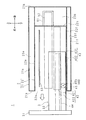
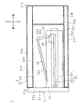
図4は、本発明の実施の形態2に係る加熱調理器1の内部構成を模式的に示す平面図である。
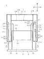
図5及び図6は、加熱調理器1の内部構成を模式的に示す側面図である。図5は収納体3が加熱室22の内部から突出している場合を示し、図6は収納体3が加熱室22の内部に没入している場合を示している。
図4と図5及び図6とは、実施の形態1の図2と図3とに対応する。ただし、図4〜図6において、スライドレール43、ラックギア44、ピニオンギア45、モータ46、マグネトロン51、及び導波管52の図示は省略している。
本実施の形態の加熱調理器1は、実施の形態1の加熱調理器1と略同様の構成である。以下では、実施の形態1との差異について説明し、その他、実施の形態1に対応する部分には同一符号を付してそれらの説明を省略する。
FIG. 4 is a plan view schematically showing the internal configuration of the
5 and 6 are side views schematically showing the internal configuration of the
4, 5, and 6 correspond to FIGS. 2 and 3 of the first embodiment. 4 to 6, illustration of the
The
加熱調理器1は、実施の形態1のヒータ53に替えて、ヒータ54を備えている。ヒータ53は固定式であるが、ヒータ54は可動式である。
ヒータ54は、適宜に屈曲された1本の金属管を用いてなるヒータ本体541と、ヒータ本体541の一端部及び他端部に取り付けられている非発熱部542,55と、付勢部543とを一体的に有する。
The
The
ヒータ本体541は実施の形態1のヒータ本体531に対応するが、ヒータ本体541の形状はコ字状又はU字状等である。ヒータ本体541は、非発熱部542,55を介して加熱室22の左側壁22c及び右側壁22dに可動支持されている。
ヒータ本体541は、収納体3の出没に伴って揺動する。ヒータ本体541の揺動範囲は、加熱室22の天壁22e近傍(少なくとも加熱室22の上下方向中央部よりも天壁22e側。例えば実施の形態1におけるヒータ本体531の配置位置)と、収納体3における被調理物の載置面(底板部35の上面)側との間である。
The heater
The heater
天壁22e側にあるヒータ本体541は収納体3の載置面に平行に、且つ、収納体3の載置面に載置される被調理物の高さよりも高い位置に配される。
載置面側にあるヒータ本体541は、天壁22e側にあるときよりも前側が下がった後傾姿勢である。載置面側にあるヒータ本体541は、収納体3の載置面に載置された被調理物の前方及び左右両側方を囲繞する。
The heater
The heater
非発熱部542は横姿勢の筒状である。非発熱部542は、加熱室22の左側壁22cを貫通して、自身の軸心を中心に回動可能に左側壁22cに支持されている。
非発熱部55は回動部551と揺動部552とを一体的に有する。
回動部551は横姿勢の筒状である。回動部551は、加熱室22の右側壁22dを貫通して、自身の軸心を中心に回動可能に右側壁22dに支持されている。
非発熱部542及び回動部551の回動に伴って、ヒータ本体541は揺動する。
The
The
The rotating part 551 has a cylindrical shape in a horizontal posture. The rotating portion 551 penetrates the
The heater
揺動部552は、低温領域23dにおいて、回動部551の右端部(即ち、回動部551における加熱室22の外部側の端部)に突設してある。揺動部552の突設方向は回動部551の軸長方向に直交し、概ね下向きである。回動部551の回動に伴って、揺動部552は、縦姿勢になる第1位置(図5参照)と前傾姿勢になる第2位置(図6参照)との間で揺動する。
付勢部543は、例えば渦巻ばねを用いてなり、低温領域23dにおいて、回動部551に取り付けられている。付勢部543は、回動部551が所定の一方向に回転するよう回動部551を付勢する。回動部551が所定の一方向に回転すると、ヒータ本体541が加熱室22の天壁22e側に揺動すると共に、揺動部552が第1位置側に揺動する。
The
The urging
ヒータ本体541に給電する図示しない給電線は、加熱室22の外部に配されており、非発熱部542,55の内部を通してヒータ本体541に電気的に接続されている。
A power supply line (not shown) that supplies power to the heater
スライドレール42の可動レール422には、接離部56が設けられている。
接離部56は、前後方向に沿う縦姿勢の板状であり、可動レール422の後端部から上向きに突出している。接離部56の上部には、前側から前後方向中央部に亘って水平面が設けられており、前後方向中央部から後部に亘って、後ろ側ほど下がる傾斜面が設けられている。
The
The contact /
接離部56は、可動レール422の前方/後方移動(即ち収納体3の出/没)に伴って、非発熱部55の揺動部552に対して離隔/接近する。収納体33の没入によって扉31が閉じるとき、接離部56の傾斜面の後端部は揺動部552の下端部に接触し、可動レール422が更に後方移動することによって、接離部56から揺動部552に徐々に外力が加わる。この外力は、付勢部543の付勢力に打ち勝って、揺動部552を第2位置側に揺動させ、揺動部552を介して回動部551を所定の一方向の逆方向に回転させる。この結果、ヒータ本体541が、加熱室22の内部に没入した収納体3の載置面側に揺動する。
The contact /
以上のような付勢部543、揺動部552、及び接離部56は、収納体3の出/没に連動してヒータ54を加熱室22の天壁22e側/被調理物の収納位置側に揺動させる揺動機構57として機能する。
The biasing
以上のような加熱調理器1は、実施の形態1の加熱調理器1と同様の作用効果を奏する上に、可動式のヒータ54によって、被調理物を適切に加熱する。
ヒータ54は、収納体3の出没に伴って自動的に揺動するので、使用者が手動で揺動させる必要がない。即ち、使用者の利便性が向上する。本実施の形態では、収納体3はモータ46に駆動されて出没する。即ち、ヒータ54を揺動させるためのアクチュエータを別途備えている必要がない。
なお、ヒータ54を揺動させるためのアクチュエータを別途備えている構成でもよい。
The
Since the
In addition, the structure which is provided with the actuator for rocking | fluctuating the
収納体3が加熱室22の内部に没入している場合、接離部56が揺動部552に接触し、揺動部552を介してヒータ54を加熱室22の載置面側へ揺動させる。このとき、ヒータ54と加熱室22の載置面に載置された被調理物との離隔距離が短くなるので、被調理物が効率よく加熱される。
一方、収納体3が加熱室22の内部から突出している場合は、接離部56が揺動部552から離隔し、付勢部543がヒータ54を加熱室22の天壁22e側へ揺動させる。このとき、ヒータ54と加熱室22の載置面に載置された被調理物との離隔距離が長くなるので、収納体3と共に加熱室22の内部に対して出没する被調理物に、ヒータ54が干渉することが抑制される。
When the
On the other hand, when the
実施の形態 3.
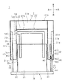
図7及び図8は、本発明の実施の形態3に係る加熱調理器1の内部構成を模式的に示す平面図及び側面図である。
図7及び図8は、実施の形態1の図2及び図3に対応する。ただし、図7及び図8において、スライドレール43の図示は省略している。また、図7では、図を見やすくするために、ラックギア44の歯が上向きであり、ピニオンギア45がラックギア44に上側から噛み合っている状態を示している。更に、図7においてマグネトロン51の図示は省略しており、図8において、スライドレール42、ラックギア44、ピニオンギア45、及びモータ46の図示は省略している。
FIG.7 and FIG.8 is the top view and side view which show typically the internal structure of the
7 and 8 correspond to FIGS. 2 and 3 of the first embodiment. However, in FIG.7 and FIG.8, illustration of the
本実施の形態の加熱調理器1は、実施の形態1の加熱調理器1と略同様の構成である。以下では、実施の形態1との差異について説明し、その他、実施の形態1に対応する部分には同一符号を付してそれらの説明を省略する。
The
加熱室22の導波口は、天壁22eに設けられている。
収納体3の背板部34は、下部に開口部341を有する。
モータ46は、ハウジング46aから出力軸46bが左方向へ突出する姿勢で低温領域23dに配されている。ハウジング46aは、筐体21の右側壁21dの内面に取り付けられている。
導波管52は、低温領域23b及び高温領域23eにて、マグネトロン51から加熱室22の天壁22eに設けられた導波口に亘って配されている。
The waveguide port of the
The
The
The
加熱調理器1は、実施の形態1のヒータ53に替えてヒータ58を備えている。
ヒータ58は、ヒータ本体581と非発熱部582,582とを一体的に有する。これらは、実施の形態1のヒータ本体531と非発熱部532,532とに対応する。
ヒータ本体581の形状は、一筆書きの二重のコ字状又はU字状等である。
The
The
The shape of the heater
ヒータ58は、加熱室22の上下方向中央部よりも底壁22f側に配されている。ヒータ本体581は収納体3の背板部34の開口部341を貫通し、収納体3の載置面に平行に、載置面近傍に配されている。収納体3が加熱室22の内部に没入すると、ヒータ本体581は、収納体3の載置面に載置される被調理物の後方及び左右両側方を囲繞する。
The
以上のような加熱調理器1は、実施の形態1と同様の作用効果を奏する。
ところで、本実施の形態における導波管52は高温領域23eに配されている。しかしながら、導波管52は、例えばラックギア44、ピニオンギア45、及びモータ46等に比べて耐熱性が高い。しかも、ヒータ58は高温領域23eから離隔しているので、ヒータ58の発熱中であっても、高温領域23eの温度は実施の形態1の場合よりも低温である。故に、導波管52を介してマグネトロン51に熱が伝達しても、高温に起因する不都合がマグネトロン51に生じるほどではない。
なお、導波管52の配置は実施の形態1の配置と同じであってもよい。
The
By the way, the
The arrangement of the
実施の形態 4.
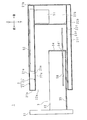
図9は、本発明の実施の形態4に係る加熱調理器1の内部構成を模式的に示す平面図である。
図9は、実施の形態1の図2に対応する。ただし、スライドレール42,43、ラックギア44、ピニオンギア45、及びモータ46の図示は省略している。
本実施の形態の加熱調理器1は、実施の形態1の加熱調理器1と略同様の構成である。以下では、実施の形態1との差異について説明し、その他、実施の形態1に対応する部分には同一符号を付してそれらの説明を省略する。
加熱調理器1は、可動アンテナ61、駆動部62、送風部63、通風路64、アンテナ室661、及び駆動室662を備えている。
FIG. 9 is a plan view schematically showing the internal configuration of the
FIG. 9 corresponds to FIG. 2 of the first embodiment. However, illustration of the slide rails 42 and 43, the
The
The
アンテナ室661及び駆動室662は、左右方向に隣接して低温領域23dに設けられている。
アンテナ室661においては、縦姿勢の円盤状の可動アンテナ61が、加熱室22の右側壁22dに対面配置されている。
駆動室662には、駆動部62が配されている。本実施の形態の駆動部62はモータを用いてなる。駆動部62の出力軸は、アンテナ室661と駆動室662とを隔てる隔壁を貫通しており、アンテナ室661の内部にて、可動アンテナ61の中心位置に連結されている。駆動部62は、可動アンテナ61を駆動する。即ち、駆動部62の出力軸が回転すると、可動アンテナ61が回転する。
The
In the
A
導波管52は、低温領域23b,23dにて、マグネトロン51からアンテナ室661に亘って配されている。マグネトロン51が発したマイクロ波は、導波管52に導かれ、アンテナ室661にて回転する可動アンテナ61によって加熱室22の内部へ散乱する。
The
送風部63は、冷却のための空気を送風する。
通風路64は、送風部63とマグネトロン51及び駆動室662夫々とに亘って配されている。
送風部63が送風した空気は、通風路64を通ってマグネトロン51及び駆動部62夫々に吹き付けられ、これらを冷却する。従って、マグネトロン51又は駆動部62の異常発熱、及び、異常発熱に起因するマグネトロン51又は駆動部62に係る不都合の発生が抑制される。
なお、送風部63が送風した空気は、マグネトロン51及び駆動部62のみならず、モータ46にも吹き付けられる構成でもよい。
The
The
The air blown by the
The air blown by the
以上のような加熱調理器1は、実施の形態1と同様の作用効果を奏する。
The
最後に、本発明の実施の形態についてまとめる。 Finally, embodiments of the present invention will be summarized.
本発明に係る加熱調理器1は、正面側に開口部22aが設けられた加熱室22を有する調理器本体2と、前記加熱室22の内部に対して前記開口部22aを通して出没可能に支持され、被調理物が収納される収納体3と、該収納体3を出没させるためのモータ46と、マグネトロン51と、該マグネトロン51が発したマイクロ波を前記加熱室22の内部へ導くための導波管52とを備え、前記モータ46、前記マグネトロン51、及び前記導波管52は、前記加熱室22の外部に配されている加熱調理器1において、前記加熱室22の内部の天壁22e側又は底壁22f側に配されるヒータ53,54,58を備え、前記モータ46は、前記加熱室22の天壁22e及び底壁22fの何れかに対向する高温領域23e,23f以外の低温領域23b,23c,23dに配されていることを特徴とする。
The
本発明に係る加熱調理器1は、前記ヒータ53,54,58は、前記加熱室22の内部の天壁22e側に配されており、前記マグネトロン51は、前記加熱室22の後壁22b又は左側壁22c(右側壁22d)に対向する前記低温領域23b,23c,23dに配され、前記導波管52は、前記加熱室22の後壁22b又は左側壁22c(右側壁22d)に対向する前記低温領域23b,23c,23dか、或いは前記底壁22fに対向する前記高温領域23e,23fに配されていることを特徴とする。
In the
本発明に係る加熱調理器1は、前記ヒータ54は、前記加熱室22の内部の天壁22e側と、該天壁22e側より低い前記被調理物の収納位置側との間で揺動可能に支持してあり、前記収納体3の出/没に連動して前記ヒータ54を前記天壁22e側/前記収納位置側に揺動させる揺動機構57を備えることを特徴とする。
In the
本発明に係る加熱調理器1は、前記収納体3は、前記開口部22aを開閉する扉31を一体的に有し、前記揺動機構57は、前記ヒータ54と共に揺動する揺動部552と、前記ヒータ54に対し、該ヒータ54が前記天壁22e側に揺動する方向へ付勢する付勢部543と、前記収納体3の出/没に伴って前記揺動部552に対し離隔/接近し、前記扉31が閉じるときに前記揺動部552に接触して、前記ヒータ54が前記収納位置側に揺動する方向へ前記揺動部552に外力を加える接離部56とを有することを特徴とする。
In the
本発明に係る加熱調理器1は、前記ヒータ53,54は、前記加熱室22の内部の天壁22e側に配されており、前記導波管52が導いたマイクロ波を前記加熱室22の内部へ散乱させる可動アンテナ61と、該可動アンテナ61を駆動する駆動部626と、送風部63と、該送風部63が送風した空気を前記マグネトロン51及び駆動部626夫々の側へ導くための通風路64とを備え、前記可動アンテナ61、駆動部626、送風部63、及び通風路64は、前記加熱室22の外部における前記加熱室22の後壁22b又は左側壁22c(右側壁22d)に対向する前記低温領域23b,23c,23dに配されていることを特徴とする。
In the
本発明に係る加熱調理器1は、前記収納体3を出没可能に支持するスライドレール42と、該スライドレール42に取り付けられており、前記収納体3と共に出没するラックギア44と、該ラックギア44に噛み合うピニオンギア45とを、前記加熱室22の外部における前記加熱室22の左側壁22c(右側壁22d)に対向する前記低温領域23c,23dに更に備え、前記モータ46は、前記ピニオンギア45を回転駆動するモータであり、前記左側壁22c(右側壁22d)に対向する前記低温領域23c,23dに配されていることを特徴とする。
The
本発明にあっては、ヒータは加熱室の内部の天壁側又は底壁側に配される。故に、加熱室の外部における加熱室の天壁及び底壁の何れかに対向する領域には、ヒータが発する熱が伝達し易い(即ち、この領域は高温領域である)。高温領域に配される部品は、高い耐熱性を有している必要がある。
一方、高温領域以外の領域にはヒータが発する熱が伝達し難い(即ち、この領域は低温領域である)。低温領域に配されているアクチュエータは、高い耐熱性を必要としない。
In the present invention, the heater is disposed on the top wall side or the bottom wall side inside the heating chamber. Therefore, heat generated by the heater is easily transmitted to a region facing either the top wall or the bottom wall of the heating chamber outside the heating chamber (that is, this region is a high temperature region). Parts arranged in the high temperature region need to have high heat resistance.
On the other hand, it is difficult for heat generated by the heater to be transmitted to a region other than the high temperature region (that is, this region is a low temperature region). An actuator arranged in a low temperature region does not require high heat resistance.
本発明にあっては、電磁波発生部は、加熱室の後壁又は側壁に対向する低温領域に配されている。低温領域に配されている電磁波発生部は、高い耐熱性を有している必要がない。
一方、導波管は、加熱室の後壁又は側壁に対向する低温領域か、或いは加熱室の底壁に対向する高温領域に配されている。これは、従来の加熱調理器において加熱室の上方に配されていた導波管を、加熱室の天壁に対向する高温領域から退避させたような構成である。
In the present invention, the electromagnetic wave generator is disposed in a low temperature region facing the rear wall or side wall of the heating chamber. The electromagnetic wave generation part arranged in the low temperature region does not need to have high heat resistance.
On the other hand, the waveguide is disposed in a low temperature region facing the rear wall or side wall of the heating chamber, or in a high temperature region facing the bottom wall of the heating chamber. This is a configuration in which the waveguide disposed above the heating chamber in the conventional cooking device is retracted from the high temperature region facing the top wall of the heating chamber.
一般に、導波管は、従来の加熱調理器が備えるラックギア、ピニオンギア、モータ、及び電磁波発生部等に比べれば、高温による不都合が生じ難い。また、加熱室の底壁に対向する高温領域は、加熱室の天壁に対向する高温領域ほど高温にはならないので、導波管を介して電磁波発生部に高熱が伝達しても、高温による不都合が電磁波発生部に生じ難い。故に、導波管を加熱室の底壁に対向する高温領域に配しても特段の問題はない。
以上の結果、従来同様の低耐熱性を有する安価な電磁波発生部及び導波管を用いて、加熱調理器を安価に製造することができる。
In general, in the waveguide, inconvenience due to a high temperature is unlikely to occur as compared with a rack gear, a pinion gear, a motor, an electromagnetic wave generator, and the like included in a conventional cooking device. In addition, the high temperature region facing the bottom wall of the heating chamber is not as hot as the high temperature region facing the top wall of the heating chamber, so even if high heat is transmitted to the electromagnetic wave generation unit via the waveguide, Inconvenience hardly occurs in the electromagnetic wave generating part. Therefore, there is no particular problem even if the waveguide is disposed in a high temperature region facing the bottom wall of the heating chamber.
As a result, the cooking device can be manufactured at low cost by using an inexpensive electromagnetic wave generator and a waveguide having low heat resistance as in the prior art.
本発明にあっては、加熱調理器が備えるヒータは可動ヒータである。
ヒータの揺動は、収納体の出没に連動する。従って、使用者が手動でヒータを揺動させる必要がない。
In the present invention, the heater provided in the cooking device is a movable heater.
The swing of the heater is linked to the appearance of the storage body. Therefore, it is not necessary for the user to manually swing the heater.
本発明にあっては、収納体が加熱室の内部に没入している場合は、接離部が揺動部に接触し、揺動部を介してヒータを加熱室の内部の被調理物の収納位置側へ揺動させる。つまり、ヒータは、収納体が加熱室に没入している場合は加熱室の内部の被調理物の収納位置側にある。故に、ヒータと被調理物との離隔距離が短いので、被調理物が効率よく加熱される。 In the present invention, when the storage body is immersed in the heating chamber, the contacting / separating portion contacts the swinging portion, and the heater is connected to the cooking object inside the heating chamber via the swinging portion. Swing to the storage position side. That is, the heater is on the side of the storage position of the cooking object inside the heating chamber when the storage body is immersed in the heating chamber. Therefore, since the separation distance between the heater and the object to be cooked is short, the object to be cooked is efficiently heated.
一方、収納体が加熱室の内部から突出している場合は、接離部が揺動部から離隔し、付勢部がヒータを加熱室の内部の天壁側へ揺動させる。つまり、ヒータは、収納体が加熱室から突出している場合は加熱室の天壁側にある。故に、ヒータと被調理物との離隔距離が長いので、収納体と共に加熱室に対して出没する被調理物に、ヒータが干渉することが抑制される。
以上のような構成では、ヒータを自動的に揺動させるためのアクチュエータは不要である。
On the other hand, when the storage body protrudes from the inside of the heating chamber, the contacting / separating portion is separated from the swinging portion, and the biasing portion swings the heater toward the top wall inside the heating chamber. That is, the heater is on the top wall side of the heating chamber when the storage body protrudes from the heating chamber. Therefore, since the separation distance of a heater and a to-be-cooked object is long, it is suppressed that a heater interferes with the to-be-cooked object which appears and disappears with respect to a heating chamber with a storage body.
In the above configuration, an actuator for automatically swinging the heater is not necessary.
本発明にあっては、送風部は、電磁波発生部及び駆動部に対して送風することによって、これらの温度上昇を抑制する。 In this invention, a ventilation part suppresses these temperature rises by blowing with respect to an electromagnetic wave generation part and a drive part.
本発明にあっては、スライドレール、ラックギア、ピニオンギア、及びアクチュエータとしてのモータは、加熱室の側壁に対向する低温領域に配されている。これは、従来の加熱調理器において下側スライドレールに配されていたラックギア、ピニオンギア、及びモータを、両側スライドレールの少なくとも一方に移動させたような構成である。
低温領域に配されているスライドレール、ラックギア、ピニオンギア、及びモータは、高い耐熱性を有している必要がないので、これらが従来同様の低耐熱性を有する安価なものであっても特段の問題はない。この結果、加熱調理器を安価に製造することができる。
In the present invention, the slide rail, the rack gear, the pinion gear, and the motor as the actuator are arranged in a low temperature region facing the side wall of the heating chamber. This is a configuration in which the rack gear, the pinion gear, and the motor that are arranged on the lower slide rail in the conventional cooking device are moved to at least one of the slide rails on both sides.
Since slide rails, rack gears, pinion gears, and motors arranged in a low temperature area do not need to have high heat resistance, even if they are inexpensive and have low heat resistance similar to the conventional ones, There is no problem. As a result, the cooking device can be manufactured at a low cost.
今回開示された実施の形態は、全ての点で例示であって、制限的なものではないと考えられるべきである。本発明の範囲は、上述した意味ではなく、特許請求の範囲と均等の意味及び特許請求の範囲内での全ての変更が含まれることが意図される。
また、本発明の効果がある限りにおいて、加熱調理器1に、実施の形態1〜4に開示されていない構成要素が含まれていてもよい。
各実施の形態に開示されている構成要件(技術的特徴)はお互いに組み合わせ可能であり、組み合わせによって新しい技術的特徴を形成することができる。
The embodiment disclosed this time is to be considered as illustrative in all points and not restrictive. The scope of the present invention is not intended to include the above-described meanings, but is intended to include meanings equivalent to the claims and all modifications within the scope of the claims.
Moreover, as long as there exists an effect of this invention, the component which is not disclosed by Embodiment 1-4 may be contained in the
The constituent elements (technical features) disclosed in each embodiment can be combined with each other, and a new technical feature can be formed by the combination.
1 加熱調理器
2 調理器本体
22 加熱室
23b,23c,23d 低温領域
23e,23f 高温領域
3 収納体
31 扉
42 スライドレール
44 ラックギア
45 ピニオンギア
46 モータ(アクチュエータ)
51 マグネトロン(電磁波発生部)
52 導波管
53,54,58 ヒータ
543 付勢部
552 揺動部
56 接離部
57 揺動機構
6 駆動部
61 可動アンテナ
62 駆動部
63 送風部
64 通風路
DESCRIPTION OF
51 Magnetron (electromagnetic wave generator)
52
Claims (5)
前記加熱室の内部に対して前記開口部を通して出没可能に支持され、被調理物が収納される収納体と、
該収納体を出没させるためのアクチュエータと、
電磁波発生部と、
該電磁波発生部が発した電磁波を前記加熱室の内部へ導くための導波管と
を備え、
前記アクチュエータ、前記電磁波発生部、及び前記導波管は、前記加熱室の外部に配されている加熱調理器において、
前記加熱室の内部の天壁側又は底壁側に配されるヒータ
を備え、
前記アクチュエータは、前記加熱室の天壁及び底壁の何れかに対向する高温領域以外の低温領域に配されていることを特徴とする加熱調理器。 A cooker body having a heating chamber provided with an opening on the front side;
A storage body that is supported so as to be able to appear and disappear through the opening with respect to the inside of the heating chamber, and in which a cooking object is stored,
An actuator for retracting the storage body;
An electromagnetic wave generator,
A waveguide for guiding the electromagnetic wave generated by the electromagnetic wave generator to the inside of the heating chamber,
In the heating cooker, the actuator, the electromagnetic wave generation unit, and the waveguide are arranged outside the heating chamber,
A heater disposed on the top wall side or bottom wall side inside the heating chamber,
The cooking device according to claim 1, wherein the actuator is arranged in a low temperature region other than the high temperature region facing either the top wall or the bottom wall of the heating chamber.
前記電磁波発生部は、前記加熱室の後壁又は側壁に対向する前記低温領域に配され、
前記導波管は、前記加熱室の後壁又は側壁に対向する前記低温領域か、或いは前記底壁に対向する前記高温領域に配されていることを特徴とする請求項1に記載の加熱調理器。 The heater is arranged on the top wall side inside the heating chamber,
The electromagnetic wave generator is disposed in the low temperature region facing the rear wall or side wall of the heating chamber,
2. The cooking according to claim 1, wherein the waveguide is disposed in the low temperature region facing a rear wall or a side wall of the heating chamber or in the high temperature region facing the bottom wall. vessel.
前記収納体の出/没に連動して前記ヒータを前記天壁側/前記収納位置側に揺動させる揺動機構を備えることを特徴とする請求項1又は2に記載の加熱調理器。 The heater is supported so as to be swingable between a top wall side inside the heating chamber and a storage position side of the cooking object lower than the top wall side,
3. The cooking device according to claim 1, further comprising a swinging mechanism that swings the heater toward the top wall side / the storage position side in association with the storage / extraction of the storage body.
前記揺動機構は、
前記ヒータと共に揺動する揺動部と、
前記ヒータに対し、該ヒータが前記天壁側に揺動する方向へ付勢する付勢部と、
前記収納体の出/没に伴って前記揺動部に対し離隔/接近し、前記扉が閉じるときに前記揺動部に接触して、前記ヒータが前記収納位置側に揺動する方向へ前記揺動部に外力を加える接離部と
を有することを特徴とする請求項3に記載の加熱調理器。 The storage body integrally has a door that opens and closes the opening,
The swing mechanism is
A swinging part swinging together with the heater;
A biasing portion that biases the heater in a direction in which the heater swings toward the top wall;
As the storage body comes in and out, it moves away / approaches with respect to the swinging portion, contacts the swinging portion when the door is closed, and the heater swings toward the storage position. The cooking device according to claim 3, further comprising a contact / separation portion that applies an external force to the swinging portion.
前記導波管が導いた電磁波を前記加熱室の内部へ散乱させる可動アンテナと、
該可動アンテナを駆動する駆動部と、
送風部と、
該送風部が送風した空気を前記電磁波発生部及び駆動部夫々の側へ導くための通風路と
を備え、
前記可動アンテナ、駆動部、送風部、及び通風路は、前記加熱室の外部における前記加熱室の後壁又は側壁に対向する前記低温領域に配されていることを特徴とする請求項1から4の何れかひとつに記載の加熱調理器。 The heater is arranged on the top wall side inside the heating chamber,
A movable antenna that scatters electromagnetic waves guided by the waveguide into the heating chamber;
A drive unit for driving the movable antenna;
A blowing section;
A ventilation path for guiding the air blown by the blower to the electromagnetic wave generator and the drive unit, respectively.
The said movable antenna, a drive part, a ventilation part, and a ventilation path are distribute | arranged to the said low-temperature area | region facing the rear wall or side wall of the said heating chamber in the exterior of the said heating chamber. The cooking device according to any one of the above.
Priority Applications (4)
| Application Number | Priority Date | Filing Date | Title |
|---|---|---|---|
| JP2014177261A JP2016050737A (en) | 2014-09-01 | 2014-09-01 | Heating cooker |
| CA2940468A CA2940468C (en) | 2014-08-29 | 2015-08-21 | Heating cooker |
| PCT/JP2015/073626 WO2016031737A1 (en) | 2014-08-29 | 2015-08-21 | Cooking device |
| US15/121,853 US10154549B2 (en) | 2014-08-29 | 2015-08-21 | Heating cooker |
Applications Claiming Priority (1)
| Application Number | Priority Date | Filing Date | Title |
|---|---|---|---|
| JP2014177261A JP2016050737A (en) | 2014-09-01 | 2014-09-01 | Heating cooker |
Publications (1)
| Publication Number | Publication Date |
|---|---|
| JP2016050737A true JP2016050737A (en) | 2016-04-11 |
Family
ID=55658371
Family Applications (1)
| Application Number | Title | Priority Date | Filing Date |
|---|---|---|---|
| JP2014177261A Pending JP2016050737A (en) | 2014-08-29 | 2014-09-01 | Heating cooker |
Country Status (1)
| Country | Link |
|---|---|
| JP (1) | JP2016050737A (en) |
Cited By (2)
| Publication number | Priority date | Publication date | Assignee | Title |
|---|---|---|---|---|
| JP2020136090A (en) * | 2019-02-20 | 2020-08-31 | 光洋サーモシステム株式会社 | Heat treatment unit, heat treatment device and heater design method for heat treatment device |
| CN116358007A (en) * | 2023-03-17 | 2023-06-30 | 芜湖美的智能厨电制造有限公司 | oven stove |
-
2014
- 2014-09-01 JP JP2014177261A patent/JP2016050737A/en active Pending
Cited By (2)
| Publication number | Priority date | Publication date | Assignee | Title |
|---|---|---|---|---|
| JP2020136090A (en) * | 2019-02-20 | 2020-08-31 | 光洋サーモシステム株式会社 | Heat treatment unit, heat treatment device and heater design method for heat treatment device |
| CN116358007A (en) * | 2023-03-17 | 2023-06-30 | 芜湖美的智能厨电制造有限公司 | oven stove |
Similar Documents
| Publication | Publication Date | Title |
|---|---|---|
| US10154549B2 (en) | Heating cooker | |
| EP3680559B1 (en) | Cooking appliance | |
| JP6837193B2 (en) | Cooker | |
| KR20120126215A (en) | Door of electric oven | |
| CN107692810B (en) | Drawer cooking utensils | |
| JP5334938B2 (en) | Cooker | |
| KR101064766B1 (en) | Steam Cooker | |
| JP2016050737A (en) | Heating cooker | |
| JP2006207874A (en) | Heating cooker | |
| JP6082987B2 (en) | Induction heating cooker | |
| JP2009024916A (en) | Superheated steam generation unit and food cooking device | |
| JP5957680B2 (en) | Microwave heating device | |
| JP2009024914A (en) | Food cooking device | |
| JP2008067997A (en) | High frequency heating device | |
| JP5247783B2 (en) | Cooker | |
| JP6693025B2 (en) | Heating cooker | |
| JP4566079B2 (en) | Toaster oven | |
| CN215777515U (en) | Cooking utensil | |
| JP2006210034A (en) | Heating cooker | |
| KR101181572B1 (en) | Cooking appliance | |
| KR100863838B1 (en) | Cooker | |
| CN114207358B (en) | Drawer type heating cooker | |
| KR100672456B1 (en) | Microwave | |
| CN100504182C (en) | Micro-wave oven | |
| JP5764711B1 (en) | Cooker |