JP2016038457A - Sound insulation - Google Patents
Sound insulation Download PDFInfo
- Publication number
- JP2016038457A JP2016038457A JP2014161245A JP2014161245A JP2016038457A JP 2016038457 A JP2016038457 A JP 2016038457A JP 2014161245 A JP2014161245 A JP 2014161245A JP 2014161245 A JP2014161245 A JP 2014161245A JP 2016038457 A JP2016038457 A JP 2016038457A
- Authority
- JP
- Japan
- Prior art keywords
- insulating material
- space
- sound insulating
- sound
- independent
- Prior art date
- Legal status (The legal status is an assumption and is not a legal conclusion. Google has not performed a legal analysis and makes no representation as to the accuracy of the status listed.)
- Granted
Links
- 238000009413 insulation Methods 0.000 title description 10
- 239000011810 insulating material Substances 0.000 claims abstract description 175
- 239000012774 insulation material Substances 0.000 claims description 9
- 230000000694 effects Effects 0.000 description 30
- 229920005992 thermoplastic resin Polymers 0.000 description 8
- 239000000463 material Substances 0.000 description 7
- 230000002093 peripheral effect Effects 0.000 description 7
- 238000011156 evaluation Methods 0.000 description 6
- 230000005540 biological transmission Effects 0.000 description 3
- 239000011162 core material Substances 0.000 description 3
- 238000004049 embossing Methods 0.000 description 3
- 238000010030 laminating Methods 0.000 description 2
- 238000005192 partition Methods 0.000 description 2
- 239000004743 Polypropylene Substances 0.000 description 1
- 238000004519 manufacturing process Methods 0.000 description 1
- 229920005672 polyolefin resin Polymers 0.000 description 1
- -1 polypropylene Polymers 0.000 description 1
- 229920001155 polypropylene Polymers 0.000 description 1
Images


Landscapes
- Building Environments (AREA)
- Vehicle Interior And Exterior Ornaments, Soundproofing, And Insulation (AREA)
- Soundproofing, Sound Blocking, And Sound Damping (AREA)
Abstract
【課題】より広い周波数帯の音を遮音することのできる遮音材を提供する。【解決手段】本発明の遮音材10は、表側壁面12及び裏側壁面14を備えている。表側壁面12と裏側壁面14との間には、複数の独立空間16と、複数の独立空間16の間の空間である連続空間18が形成されている。複数の独立空間16のうち少なくとも1つの独立空間16には、音源が存在する側の空間に向けて開口する孔Pが形成されている。連続空間18には、音源が存在する側の空間に向けて開口する孔Pが形成されている。【選択図】図1The present invention provides a sound insulating material capable of insulating sound in a wider frequency band. A sound insulating material of the present invention includes a front side wall surface and a back side wall surface. A plurality of independent spaces 16 and a continuous space 18 that is a space between the plurality of independent spaces 16 are formed between the front side wall surface 12 and the back side wall surface 14. At least one independent space 16 among the plurality of independent spaces 16 is formed with a hole P that opens toward the space where the sound source exists. The continuous space 18 is formed with a hole P that opens toward the space on the side where the sound source exists. [Selection] Figure 1
Description
本発明は、遮音材に関する。 The present invention relates to a sound insulating material.
従来、車室内側に向けて開口する開口部を有する閉塞空間からなる車室内側レゾネータ構造と、車室外側に向けて開口する開口部を有する閉塞空間からなる車室外側レゾネータ構造と、を有することを特徴とする車両用内装材が知られている(特許文献1参照)。この車両用内装材は、表側基材及び裏側基材を備えており、前記表側基材及び前記裏側基材の間には空間が形成されており、前記空間は、格子状のリブによって複数の部屋に区画されている。前記複数の部屋のうち、車室内側に向けて開口する開口部を有する部屋によって車室内側レゾネータ構造が形成されており、車室外側に向けて開口する開口部を有する部屋によって車室外側レゾネータ構造が形成されている。この車両用内装材によれば、表側及び裏側に音波が入射するための開口部が設けられているために、車室内側の騒音だけでなく、車室外側の騒音を遮音することができる。 Conventionally, it has a vehicle interior side resonator structure consisting of a closed space having an opening that opens toward the vehicle interior side, and a vehicle interior outside resonator structure consisting of a closed space having an opening that opens toward the vehicle exterior side. A vehicle interior material characterized by this is known (see Patent Document 1). The vehicle interior material includes a front-side base material and a back-side base material, and a space is formed between the front-side base material and the back-side base material, and the space includes a plurality of lattice-shaped ribs. It is divided into rooms. Of the plurality of rooms, a vehicle interior side resonator structure is formed by a room having an opening opening toward the vehicle interior side, and a vehicle interior outside resonator is formed by a room having an opening opening toward the vehicle exterior side. A structure is formed. According to this vehicle interior material, since openings for allowing sound waves to enter on the front side and the back side are provided, not only the noise on the vehicle interior side but also the noise on the vehicle exterior side can be insulated.
しかし、特許文献1に開示されたような従来の遮音材は、複数の開口部の大きさ(直径)が同じであるとともに、複数の閉塞空間の容積が同じであるため、共鳴周波数が一定であり、特定の狭い周波数帯の音を遮音できるのみであった。
However, the conventional sound insulating material as disclosed in
本発明の目的の1つは、より広い周波数帯の音を遮音することのできる遮音材を提供することである。 One of the objects of the present invention is to provide a sound insulating material capable of insulating sound in a wider frequency band.
課題を解決するための手段は、以下の発明である。
表側壁面及び裏側壁面を備えた遮音材であって、
前記表側壁面と前記裏側壁面との間には、複数の独立空間と、前記複数の独立空間の間の空間である連続空間が形成されており、
前記複数の独立空間のうち少なくとも1つの独立空間には、音源が存在する側の空間に向けて開口する孔が形成されており、
前記連続空間には、音源が存在する側の空間に向けて開口する孔が形成されていることを特徴とする、遮音材。
Means for solving the problems are the following inventions.
A sound insulating material having a front side wall surface and a back side wall surface,
Between the front side wall surface and the back side wall surface, a plurality of independent spaces and a continuous space that is a space between the plurality of independent spaces are formed,
At least one independent space among the plurality of independent spaces is formed with a hole that opens toward the space on the side where the sound source exists,
The sound insulating material, wherein the continuous space is formed with a hole that opens toward the space on the side where the sound source exists.
上記遮音材において、前記連続空間に形成された孔の直径よりも、前記独立空間に形成された孔の直径の方が大きい。 In the sound insulating material, the diameter of the hole formed in the independent space is larger than the diameter of the hole formed in the continuous space.
上記遮音材において、前記独立空間に形成された孔の直径よりも、前記連続空間に形成された孔の直径の方が大きい。 In the sound insulating material, the diameter of the hole formed in the continuous space is larger than the diameter of the hole formed in the independent space.
上記遮音材において、前記連続空間に形成された孔の直径と、前記独立空間に形成された孔の直径が同じである。 In the above sound insulating material, the diameter of the hole formed in the continuous space is the same as the diameter of the hole formed in the independent space.
上記遮音材において、前記独立空間にのみ孔を形成したときの遮音材の共鳴周波数と、前記連続空間にのみ孔を形成したときの遮音材の共鳴周波数とがほぼ等しくなるように、前記独立空間及び前記連続空間に形成された孔の大きさがそれぞれ設定されている。 In the above sound insulating material, the independent space is set such that the resonance frequency of the sound insulating material when the hole is formed only in the independent space and the resonance frequency of the sound insulating material when the hole is formed only in the continuous space are substantially equal. The size of the holes formed in the continuous space is set.
前記独立空間の形状が略円錐台状、略円錐状、あるいは略円柱状である。 The independent space has a substantially truncated cone shape, a substantially conical shape, or a substantially cylindrical shape.
本発明によれば、より広い周波数帯の音を遮音することのできる遮音材を提供することができる。 According to the present invention, it is possible to provide a sound insulating material capable of insulating sound in a wider frequency band.
以下、本発明の実施形態について図面を参照しながら詳細に説明する。
以下の実施形態では、まず、遮音材の例として、第1の遮音材、第2の遮音材、及び、第3の遮音材について説明する。
Hereinafter, embodiments of the present invention will be described in detail with reference to the drawings.
In the following embodiments, first, the first sound insulating material, the second sound insulating material, and the third sound insulating material will be described as examples of the sound insulating material.
[第1の遮音材]
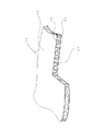
図1は、第1の遮音材の斜視図である。図2は、第1の遮音材の断面図である。
図1及び図2に示すように、第1の遮音材10は、表側壁面12及び裏側壁面14を備えている。表側壁面12と裏側壁面14との間には、複数の独立空間16と、複数の独立空間16の間の空間である連続空間18が形成されている。複数の独立空間16のうち少なくとも1つの独立空間16には、音源が存在する側の空間に向けて開口する孔Pが形成されている。連続空間18にも、音源が存在する側の空間に向けて開口する孔Pが形成されている。つまり、独立空間16及び連続空間18の両方に、音源が存在する側の空間に向けて開口する孔Pが形成されている(ただし、図1では、遮音材に孔Pが形成される前の状態を示している)。
[First sound insulating material]
FIG. 1 is a perspective view of a first sound insulating material. FIG. 2 is a cross-sectional view of the first sound insulating material.
As shown in FIGS. 1 and 2, the first sound
図2に示すように、独立空間16は、表側の独立空間16aと、裏側の独立空間16bによって構成されている。表側及び裏側の独立空間16a、16bは、中間の仕切壁16cによって仕切られている。表側及び裏側の独立空間16a、16bは、周壁部16dによって囲まれた略円錐台状の空間からなる。表側及び裏側の独立空間16a、16bは、直径が小さい方の底面において互いに突き合わせた状態で連結されており、全体として鼓状の形状を有している。
As shown in FIG. 2, the
連続空間18は、複数の独立空間16の間に形成された空間であり、連続した1つの空間からなる。連続空間18と独立空間16は、周壁部16dによって仕切られている。
The
[第2の遮音材]
図3は、第2の遮音材の斜視図である。図4は、第2の遮音材の断面図である。
図3及び図4に示すように、第2の遮音材20は、表側壁面22及び裏側壁面24を備えている。表側壁面22と裏側壁面24との間には、複数の独立空間26と、複数の独立空間26の間の空間である連続空間28が形成されている。複数の独立空間26のうち少なくとも1つの独立空間26には、音源が存在する側の空間に向けて開口する孔Pが形成されている。連続空間28にも、音源が存在する側の空間に向けて開口する孔Pが形成されている。つまり、独立空間26及び連続空間28の両方に、音源が存在する側の空間に向けて開口する孔Pが形成されている(ただし、図3では、遮音材に孔Pが形成される前の状態を示している)。
[Second sound insulation]
FIG. 3 is a perspective view of the second sound insulating material. FIG. 4 is a cross-sectional view of the second sound insulating material.
As shown in FIGS. 3 and 4, the second
図4に示すように、独立空間26は、周壁部26dによって囲まれた略円錐台状の空間からなる。連続空間28は、複数の独立空間26の間に形成された空間であり、連続した1つの空間からなる。連続空間28と独立空間26は、周壁部26dによって仕切られている。
As shown in FIG. 4, the
[第3の遮音材]
図5は、第3の遮音材の斜視図である。図6は、第3の遮音材の断面図である。
図5及び図6に示すように、第3の遮音材30は、表側壁面32及び裏側壁面34を備えている。表側壁面32と裏側壁面34との間には、複数の独立空間36と、複数の独立空間36の間の空間である連続空間38が形成されている。複数の独立空間36のうち少なくとも1つの独立空間36には、音源が存在する側の空間に向けて開口する孔Pが形成されている。連続空間38にも、音源が存在する側の空間に向けて開口する孔Pが形成されている。つまり、独立空間36及び連続空間38の両方に、音源が存在する側の空間に向けて開口する孔Pが形成されている(ただし、図5では、遮音材に孔Pが形成される前の状態を示している)。
[Third sound insulating material]
FIG. 5 is a perspective view of a third sound insulating material. FIG. 6 is a cross-sectional view of the third sound insulating material.
As shown in FIGS. 5 and 6, the third
図6に示すように、独立空間36は、周壁部36dによって囲まれた略円柱状の空間からなる。連続空間38は、複数の独立空間36の間に形成された空間であり、連続した1つの空間からなる。連続空間38と独立空間36は、周壁部36dによって仕切られている。
As shown in FIG. 6, the
上記で説明した第1の遮音材10は、例えば、二枚の熱可塑性樹脂シートにエンボスローラを用いて複数の円錐台状の凸部を突設し、突設された複数の凸部同士を突き合わせた状態で溶着してなる芯材の表裏に、熱可塑性樹脂シートを貼り合わせることによって製造することができる。第2の遮音材20は、例えば、熱可塑性樹脂シートにエンボスローラを用いて複数の円錐状の凸部を突設し、複数の凸部が突設された芯材の表裏に、熱可塑性樹脂シートを貼り合わせることによって製造することができる。第3の遮音材30は、例えば、熱可塑性樹脂シートにエンボスローラを用いて複数の円柱状の凸部を突設し、複数の凸部が突設された芯材の表裏に、熱可塑性樹脂シートを貼り合わせることによって製造することができる。熱可塑性樹脂シートとしては、例えば、ポリオレフィン系樹脂シート、特にポリプロピレンシートを用いることが好ましいが、他の熱可塑性樹脂シートを用いても良い。
In the first
上記で説明した第1〜第3の遮音材10、20、30は、公知の装置によって製造することが可能であり、例えば、特開2009−19495号公報に開示された装置によって製造することが可能である。
The first to third
本発明の遮音材によれば、利用環境や使用目的に応じて狭帯域あるいは広帯域における遮音性向上を図ることができる。
本発明の遮音材によれば、例えば、ある特定の騒音を遮音したい場合に、その騒音がもつ特定の周波数帯の音のみを重点的に遮音することができる。
本発明の遮音材によれば、例えば、狭い周波数帯の音を重点的に遮音するだけでなく、広い周波数帯の音を満遍なく遮音することもできる。
According to the sound insulating material of the present invention, it is possible to improve the sound insulating property in a narrow band or a wide band according to the use environment and the purpose of use.
According to the sound insulating material of the present invention, for example, when it is desired to insulate a specific noise, only the sound in a specific frequency band that the noise has can be focused on.
According to the sound insulating material of the present invention, for example, not only the sound of a narrow frequency band can be sound-insulated, but also the sound of a wide frequency band can be uniformly sound-insulated.
ヘルムホルツの共鳴原理によれば、共鳴器の内部容積をV(cm3)、開口部の長さをL(cm)、開口部の面積をS(cm2)、音速をc(cm/s)としたとき、共鳴器の開口部に入射する音の共鳴周波数f(Hz)は、以下の式(1)により求めることができる。
f = (c/2π)×(S/(L×V))1/2 …式(1)
According to Helmholtz's resonance principle, the internal volume of the resonator is V (cm 3 ), the length of the opening is L (cm), the area of the opening is S (cm 2 ), and the speed of sound is c (cm / s). Then, the resonance frequency f (Hz) of the sound incident on the opening of the resonator can be obtained by the following equation (1).
f = (c / 2π) × (S / (L × V)) 1/2 Formula (1)
つまり、V、S、Lの値を調整することによって、共鳴器に入射する音の共鳴周波数を異ならせることが可能である。本発明は、この原理を応用したものである。つまり、独立空間及び連続空間の容積を調整することによって、共鳴周波数を異ならせることができる。あるいは、独立空間及び連続空間に形成された孔の大きさを調整することによって、共鳴周波数を異ならせることができる。これにより、特定の狭い周波数帯の音を重点的に遮音することもできるし、広い周波数帯の音を遮音することもできる。 That is, by adjusting the values of V, S, and L, it is possible to vary the resonance frequency of the sound incident on the resonator. The present invention applies this principle. That is, the resonance frequency can be varied by adjusting the volumes of the independent space and the continuous space. Alternatively, the resonance frequency can be made different by adjusting the size of the holes formed in the independent space and the continuous space. Thereby, sound of a specific narrow frequency band can also be sound-insulated, and sound of a wide frequency band can also be sound-insulated.
以下、本発明の遮音材の効果を実証するために行った遮音性能の評価試験について説明する。
以下の説明において、「多孔効果」とは、複数の孔Pを設けていない遮音材を用いて測定した音響透過損失(dB)と、複数の孔Pを設けた遮音材を用いて測定した音響透過損失(dB)との差を意味する。音響透過損失は、残響室と無響室の間に遮音材を設置し、残響室に音源を設置するとともに、無響室にマイクロフォンを設置して測定した。
Hereinafter, the evaluation test of the sound insulation performance performed in order to demonstrate the effect of the sound insulation material of this invention is demonstrated.
In the following description, “porous effect” means sound transmission loss (dB) measured using a sound insulating material not provided with a plurality of holes P, and sound measured using a sound insulating material provided with a plurality of holes P. It means the difference from transmission loss (dB). The sound transmission loss was measured by installing a sound insulating material between the reverberation room and the anechoic room, installing a sound source in the reverberation room, and installing a microphone in the anechoic room.
[遮音性能の評価試験1]
図7(a)〜(c)は、独立空間にのみ孔が設けられた遮音材の断面図である。遮音材の形状は、上記で説明した第1の遮音材10とほぼ同じである。以下では、図7(a)〜(c)の遮音材を、遮音材(a)、遮音材(b)、遮音材(c)のように呼ぶことがある。
[Sound insulation performance evaluation test 1]
7A to 7C are cross-sectional views of the sound insulating material in which holes are provided only in the independent space. The shape of the sound insulating material is substantially the same as that of the first
遮音材(a)に設けられた孔の直径は、1.5mmである。
遮音材(b)に設けられた孔の直径は、1.0mmである。
遮音材(c)には、直径1.5mmの孔と直径1.0mmの孔が交互に設けられている。
The diameter of the hole provided in the sound insulating material (a) is 1.5 mm.
The diameter of the hole provided in the sound insulating material (b) is 1.0 mm.
The sound insulating material (c) is provided with holes having a diameter of 1.5 mm and holes having a diameter of 1.0 mm alternately.
図8は、遮音材(a)〜(c)を用いて多孔効果を測定した結果を示している。
図8に示すように、遮音材(a)の多孔効果は、周波数8kHz付近においてピークとなっており、遮音材(a)の共鳴周波数が約8kHzであると推定できる。遮音材(b)の多孔効果は、周波数6kHz付近においてピークとなっており、遮音材(b)の共鳴周波数が約6kHzであると推定できる。遮音材(c)の多孔効果は、周波数8kHz付近においてピークとなっているが、遮音材(a)よりも広い周波数帯において高い多孔効果が得られている。
FIG. 8 shows the results of measuring the porosity effect using the sound insulating materials (a) to (c).
As shown in FIG. 8, the porous effect of the sound insulating material (a) has a peak around the frequency of 8 kHz, and it can be estimated that the resonance frequency of the sound insulating material (a) is about 8 kHz. The porous effect of the sound insulating material (b) has a peak around the frequency of 6 kHz, and it can be estimated that the resonance frequency of the sound insulating material (b) is about 6 kHz. The porous effect of the sound insulating material (c) has a peak near the frequency of 8 kHz, but a high porous effect is obtained in a wider frequency band than the sound insulating material (a).
図8に示す結果より、遮音材の内部に容積が一定の複数の独立空間を設けるとともに、複数の独立空間に設ける孔の大きさを調整することによって、遮音材の共鳴周波数を調整することができることがわかる。例えば、容積が一定の複数の独立空間に同じ大きさの孔を設けることによって、特定の狭い周波数帯の音(例えば、共鳴周波数±1kHz付近の音)を重点的に遮音することができる。また、容積が一定の複数の独立空間に異なる大きさの孔を設けることによって、広い周波数帯の音を万遍なく遮音することができる。 From the results shown in FIG. 8, it is possible to adjust the resonance frequency of the sound insulating material by providing a plurality of independent spaces having a constant volume inside the sound insulating material and adjusting the size of the holes provided in the plurality of independent spaces. I understand that I can do it. For example, by providing holes of the same size in a plurality of independent spaces having a constant volume, sound of a specific narrow frequency band (for example, sound in the vicinity of the resonance frequency ± 1 kHz) can be intensively sound-insulated. In addition, by providing holes of different sizes in a plurality of independent spaces having a constant volume, it is possible to uniformly isolate sound in a wide frequency band.
[遮音性能の評価試験2]
図9(d)は、独立空間にのみ孔が設けられた遮音材の断面図である。図9(e)は、連続空間にのみ孔が設けられた遮音材の断面図である。図9(f)は、独立空間及び連続空間の両方に孔が設けられた遮音材の断面図である。遮音材の形状は、上記で説明した第1の遮音材10とほぼ同じである。以下では、図9(d)〜(f)の遮音材を、遮音材(d)、遮音材(e)、遮音材(f)のように呼ぶことがある。
[Sound insulation performance evaluation test 2]
FIG. 9D is a cross-sectional view of a sound insulating material in which a hole is provided only in an independent space. FIG.9 (e) is sectional drawing of the sound insulating material in which the hole was provided only in continuous space. FIG. 9F is a cross-sectional view of the sound insulating material in which holes are provided in both the independent space and the continuous space. The shape of the sound insulating material is substantially the same as that of the first
遮音材(d)に設けられた孔の直径は、1.5mmである。
遮音材(e)に設けられた孔の直径は、1.5mmである。
遮音材(f)の独立空間には直径1.5mmの孔が設けられており、連続空間には直径1.5mmの孔が設けられている。
The diameter of the hole provided in the sound insulating material (d) is 1.5 mm.
The diameter of the hole provided in the sound insulating material (e) is 1.5 mm.
The independent space of the sound insulating material (f) is provided with a hole having a diameter of 1.5 mm, and the continuous space is provided with a hole having a diameter of 1.5 mm.
図10は、遮音材(d)〜(f)を用いて多孔効果を測定した結果を示している。
図10に示すように、遮音材(d)の多孔効果は、周波数8kHz付近においてピークとなっており、遮音材(d)の共鳴周波数が約8kHzであると推定できる。遮音材(e)の多孔効果も、周波数8kHz付近においてピークとなっており、遮音材(e)の共鳴周波数が約8kHzであると推定できる。遮音材(f)の多孔効果は、周波数8kHz付近においてピークとなっており、遮音材(d)及び遮音材(e)よりも高い多孔効果が得られている。
FIG. 10 shows the results of measuring the porosity effect using the sound insulating materials (d) to (f).
As shown in FIG. 10, the porous effect of the sound insulating material (d) has a peak around the frequency of 8 kHz, and it can be estimated that the resonance frequency of the sound insulating material (d) is about 8 kHz. The porous effect of the sound insulating material (e) also has a peak around the frequency of 8 kHz, and it can be estimated that the resonance frequency of the sound insulating material (e) is about 8 kHz. The porous effect of the sound insulating material (f) has a peak in the vicinity of the frequency of 8 kHz, and a higher porous effect is obtained than the sound insulating material (d) and the sound insulating material (e).
図10に示す結果より、遮音材の内部に容積が一定の複数の独立空間及び連続空間を設けるとともに、複数の独立空間及び連続空間に設ける孔の大きさを調整することによって、遮音材の共鳴周波数を調整することができることがわかる。
例えば、容積が一定の複数の独立空間に同じ大きさの孔を設けることによって、特定の狭い周波数帯の音(例えば、共鳴周波数±1kHz付近の音)を重点的に遮音することができる。
From the results shown in FIG. 10, by providing a plurality of independent spaces and continuous spaces having a constant volume inside the sound insulating material, and adjusting the size of the holes provided in the plurality of independent spaces and continuous spaces, resonance of the sound insulating material is achieved. It can be seen that the frequency can be adjusted.
For example, by providing holes of the same size in a plurality of independent spaces having a constant volume, sound of a specific narrow frequency band (for example, sound in the vicinity of the resonance frequency ± 1 kHz) can be intensively sound-insulated.
また、連続空間に、同じ大きさの孔を一定のピッチで設ける事によって、特定の周波数帯の音(例えば、共鳴周波数±1kHz付近の音)を重点的に遮音することができる。 Further, by providing holes of the same size at a constant pitch in the continuous space, it is possible to focus on sound in a specific frequency band (for example, sound in the vicinity of resonance frequency ± 1 kHz).
さらに、独立空間にのみ孔を設けた場合の共鳴周波数と、連続空間にのみ孔を設けた場合の共鳴周波数とを一致させることができる。そして、独立空間及び連続空間の両方に、共鳴周波数を一致させたときと同じ大きさの孔をそれぞれ設けることによって、特定の周波数帯の音(例えば、共鳴周波数±1kHz付近の音)をより効果的に遮音できるようになる。 Furthermore, the resonance frequency when the hole is provided only in the independent space can be matched with the resonance frequency when the hole is provided only in the continuous space. And, by providing holes of the same size as when the resonance frequencies are matched in both the independent space and the continuous space, the sound of a specific frequency band (for example, the sound near the resonance frequency ± 1 kHz) is more effective. Can be sound-insulated.
図9(f)の遮音材は、独立空間にのみ孔を形成したときの遮音材の共鳴周波数と、連続空間にのみ孔を形成したときの遮音材の共鳴周波数とがほぼ等しくなるように、独立空間及び連続空間に形成された孔の大きさがそれぞれ設定されている。これにより、特定の周波数帯の音(例えば、共鳴周波数±1kHz付近の音)をより効果的に遮音できるようになる。 In the sound insulating material of FIG. 9 (f), the resonance frequency of the sound insulating material when the hole is formed only in the independent space and the resonance frequency of the sound insulating material when the hole is formed only in the continuous space are substantially equal. The sizes of the holes formed in the independent space and the continuous space are respectively set. As a result, sound in a specific frequency band (for example, sound in the vicinity of resonance frequency ± 1 kHz) can be more effectively sound-insulated.
[遮音性能の評価試験3]
図11(g)は、複数の独立空間に、同じ大きさの孔が設けられた遮音材の断面図である。図11(h)は、複数の独立空間に、異なる大きさの孔が設けられた遮音材の断面図である。遮音材の形状は、上記で説明した第2の遮音材20とほぼ同じである。以下では、図11(g)〜(h)の遮音材を、遮音材(g)、遮音材(h)のように呼ぶことがある。
[Sound insulation performance evaluation test 3]
FIG. 11G is a cross-sectional view of a sound insulating material in which holes having the same size are provided in a plurality of independent spaces. FIG. 11 (h) is a cross-sectional view of a sound insulating material in which holes of different sizes are provided in a plurality of independent spaces. The shape of the sound insulating material is substantially the same as that of the second
遮音材(g)に設けられた孔の直径は、1.0mmである。
遮音材(h)に設けられた孔の直径は、0.6mm、1.0mm、1.5mmの3種類である。
The diameter of the hole provided in the sound insulating material (g) is 1.0 mm.
The diameters of the holes provided in the sound insulating material (h) are three types of 0.6 mm, 1.0 mm, and 1.5 mm.
図12は、遮音材(g)、(h)を用いて多孔効果を測定した結果を示している。
図12に示すように、遮音材(g)の多孔効果は、周波数6kHz付近においてピークとなっており、遮音材(g)の共鳴周波数が約6kHzであると推定できる。遮音材(h)の多孔効果は、周波数5kHz付近においてピークとなっているが、遮音材(g)よりも広い周波数帯において高い多孔効果が得られている。
FIG. 12 shows the results of measuring the porosity effect using the sound insulating materials (g) and (h).
As shown in FIG. 12, the porous effect of the sound insulating material (g) has a peak around the frequency of 6 kHz, and it can be estimated that the resonance frequency of the sound insulating material (g) is about 6 kHz. The porous effect of the sound insulating material (h) has a peak near the frequency of 5 kHz, but a high porous effect is obtained in a wider frequency band than the sound insulating material (g).
図12に示す結果より、遮音材の内部に容積が一定の複数の独立空間を設けるとともに、複数の独立空間に設ける孔の大きさを調整することによって、遮音材の共鳴周波数を調整することができることがわかる。例えば、容積が一定の複数の独立空間に同じ大きさの孔を設けることによって、特定の狭い周波数帯の音(例えば、共鳴周波数±1kHz付近の音)を重点的に遮音することができる。また、容積が一定の複数の独立空間に異なる大きさの孔を設けることによって、広い周波数帯の音を万遍なく遮音することができる。 From the results shown in FIG. 12, it is possible to adjust the resonance frequency of the sound insulating material by providing a plurality of independent spaces having a constant volume inside the sound insulating material and adjusting the size of the holes provided in the plurality of independent spaces. I understand that I can do it. For example, by providing holes of the same size in a plurality of independent spaces having a constant volume, sound of a specific narrow frequency band (for example, sound in the vicinity of the resonance frequency ± 1 kHz) can be intensively sound-insulated. In addition, by providing holes of different sizes in a plurality of independent spaces having a constant volume, it is possible to uniformly isolate sound in a wide frequency band.
[遮音性能の評価試験4]
図13(i)は、独立空間にのみ孔が設けられた遮音材の断面図である。図13(j)は、独立空間及び連続空間の両方に孔が設けられた遮音材の断面図である。遮音材の形状は、上記で説明した第2の遮音材20とほぼ同じである。以下では、図13(i)〜(j)の遮音材を、遮音材(i)、遮音材(j)のように呼ぶことがある。
[Sound insulation performance evaluation test 4]
FIG. 13 (i) is a cross-sectional view of a sound insulating material in which a hole is provided only in an independent space. FIG. 13J is a cross-sectional view of the sound insulating material in which holes are provided in both the independent space and the continuous space. The shape of the sound insulating material is substantially the same as that of the second
遮音材(i)に設けられた孔の直径は、1.5mmである。
遮音材(j)の独立空間には直径1.5mmの孔が設けられており、連続空間には直径1.5mmの孔が設けられている。
The diameter of the hole provided in the sound insulating material (i) is 1.5 mm.
The independent space of the sound insulating material (j) is provided with a hole having a diameter of 1.5 mm, and the continuous space is provided with a hole having a diameter of 1.5 mm.
図14は、遮音材(i)〜(j)を用いて多孔効果を測定した結果を示している。
図14に示すように、遮音材(i)の多孔効果は、周波数8kHz付近においてピークとなっており、遮音材(i)の共鳴周波数が約8kHzであると推定できる。遮音材(j)の多孔効果は、周波数8kHz付近においてピークとなっており、遮音材(i)よりも高い多孔効果が得られている。
FIG. 14 shows the results of measuring the porosity effect using the sound insulating materials (i) to (j).
As shown in FIG. 14, the porous effect of the sound insulating material (i) has a peak in the vicinity of the frequency of 8 kHz, and it can be estimated that the resonance frequency of the sound insulating material (i) is about 8 kHz. The porous effect of the sound insulating material (j) has a peak in the vicinity of the frequency of 8 kHz, and a higher porous effect than that of the sound insulating material (i) is obtained.
図14に示す結果より、遮音材の内部に容積が一定の複数の独立空間及び連続空間を設けるとともに、複数の独立空間及び連続空間に設ける孔の大きさを調整することによって、遮音材の共鳴周波数を調整することができることがわかる。
例えば、容積が一定の複数の独立空間に同じ大きさの孔を設けることによって、特定の狭い周波数帯の音(例えば、共鳴周波数±1kHz付近の音)を重点的に遮音することができる。
From the results shown in FIG. 14, by providing a plurality of independent spaces and continuous spaces having a constant volume inside the sound insulating material, and adjusting the size of the holes provided in the plurality of independent spaces and continuous spaces, the resonance of the sound insulating material is achieved. It can be seen that the frequency can be adjusted.
For example, by providing holes of the same size in a plurality of independent spaces having a constant volume, sound of a specific narrow frequency band (for example, sound in the vicinity of the resonance frequency ± 1 kHz) can be intensively sound-insulated.
また、連続空間に、同じ大きさの孔を一定のピッチで設ける事によって、特定の周波数帯の音(例えば、共鳴周波数±1kHz付近の音)を重点的に遮音することができる。 Further, by providing holes of the same size at a constant pitch in the continuous space, it is possible to focus on sound in a specific frequency band (for example, sound in the vicinity of resonance frequency ± 1 kHz).
さらに、独立空間にのみ孔を設けた場合の共鳴周波数と、連続空間にのみ孔を設けた場合の共鳴周波数とを一致させることができる。そして、独立空間及び連続空間の両方に、共鳴周波数を一致させたときと同じ大きさの孔をそれぞれ設けることによって、特定の狭い周波数帯の音(例えば、共鳴周波数±1kHz付近の音)をより効果的に遮音できるようになる。 Furthermore, the resonance frequency when the hole is provided only in the independent space can be matched with the resonance frequency when the hole is provided only in the continuous space. Then, by providing holes of the same size as when the resonance frequencies are matched in both the independent space and the continuous space, sounds of a specific narrow frequency band (for example, sounds in the vicinity of resonance frequency ± 1 kHz) can be obtained more. Effective sound insulation is achieved.
図13(j)の遮音材は、独立空間にのみ孔を形成したときの遮音材の共鳴周波数と、連続空間にのみ孔を形成したときの遮音材の共鳴周波数とがほぼ等しくなるように、独立空間及び連続空間に形成された孔の大きさがそれぞれ設定されている。これにより、特定の周波数帯の音(例えば、共鳴周波数±1kHz付近の音)をより効果的に遮音できるようになる。 In the sound insulating material of FIG. 13 (j), the resonance frequency of the sound insulating material when the hole is formed only in the independent space is substantially equal to the resonance frequency of the sound insulating material when the hole is formed only in the continuous space. The sizes of the holes formed in the independent space and the continuous space are respectively set. As a result, sound in a specific frequency band (for example, sound in the vicinity of resonance frequency ± 1 kHz) can be more effectively sound-insulated.
[遮音性能の評価試験5]
図15(k)は、独立空間にのみ孔が設けられた遮音材の断面図である。図15(l)は、連続空間にのみ孔が設けられた遮音材の断面図である。図15(m)は、独立空間及び連続空間の両方に孔が設けられた遮音材の断面図である。遮音材の形状は、上記で説明した第3の遮音材30とほぼ同じである。以下では、図15(k)〜(m)の遮音材を、遮音材(k)、遮音材(l)、遮音材(m)のように呼ぶことがある。
[Sound insulation performance evaluation test 5]
FIG. 15 (k) is a cross-sectional view of a sound insulating material in which a hole is provided only in an independent space. FIG. 15L is a cross-sectional view of a sound insulating material in which holes are provided only in a continuous space. FIG. 15 (m) is a cross-sectional view of the sound insulating material in which holes are provided in both the independent space and the continuous space. The shape of the sound insulating material is substantially the same as that of the third
遮音材(k)に設けられた孔の直径は、1.0mmである。
遮音材(l)に設けられた孔の直径は、1.0mmである。
遮音材(m)の独立空間には直径1.0mmの孔が設けられており、連続空間には直径1.0mmの孔が設けられている。
The diameter of the hole provided in the sound insulating material (k) is 1.0 mm.
The diameter of the hole provided in the sound insulating material (l) is 1.0 mm.
A hole having a diameter of 1.0 mm is provided in the independent space of the sound insulating material (m), and a hole having a diameter of 1.0 mm is provided in the continuous space.
図16は、遮音材(k)〜(m)を用いて多孔効果を測定した結果を示している。
図16に示すように、遮音材(k)の多孔効果は、周波数1.3kHz付近においてピークとなっており、遮音材(k)の共鳴周波数が約1.3kHzであると推定できる。遮音材(l)の多孔効果は、周波数1.5kHz付近においてピークとなっており、遮音材(l)の共鳴周波数が約1.5kHzであると推定できる。遮音材(m)の多孔効果は、周波数1.3〜1.5kHz付近においてピークとなっており、遮音材(k)、(l)よりも高い多孔効果が得られている。
FIG. 16 shows the results of measuring the porosity effect using the sound insulating materials (k) to (m).
As shown in FIG. 16, the porous effect of the sound insulating material (k) has a peak in the vicinity of the frequency of 1.3 kHz, and it can be estimated that the resonance frequency of the sound insulating material (k) is about 1.3 kHz. The porous effect of the sound insulating material (l) has a peak around the frequency of 1.5 kHz, and it can be estimated that the resonance frequency of the sound insulating material (l) is about 1.5 kHz. The porous effect of the sound insulating material (m) has a peak in the vicinity of a frequency of 1.3 to 1.5 kHz, and a higher porous effect than that of the sound insulating materials (k) and (l) is obtained.
図16に示す結果より、遮音材の内部に容積が一定の複数の独立空間及び連続空間を設けるとともに、複数の独立空間及び連続空間に設ける孔の大きさを調整することによって、遮音材の共鳴周波数を調整することができることがわかる。
例えば、容積が一定の複数の独立空間に同じ大きさの孔を設けることによって、特定の狭い周波数帯の音(例えば、共鳴周波数±1kHz付近の音)を重点的に遮音することができる。
From the results shown in FIG. 16, a plurality of independent spaces and continuous spaces having a constant volume are provided inside the sound insulating material, and by adjusting the size of the holes provided in the plurality of independent spaces and continuous spaces, the resonance of the sound insulating material is achieved. It can be seen that the frequency can be adjusted.
For example, by providing holes of the same size in a plurality of independent spaces having a constant volume, sound of a specific narrow frequency band (for example, sound in the vicinity of the resonance frequency ± 1 kHz) can be intensively sound-insulated.
また、連続空間に、同じ大きさの孔を一定のピッチで設ける事によって、特定の周波数帯の音(例えば、共鳴周波数±1kHz付近の音)を重点的に遮音することができる。 Further, by providing holes of the same size at a constant pitch in the continuous space, it is possible to focus on sound in a specific frequency band (for example, sound in the vicinity of resonance frequency ± 1 kHz).
さらに、独立空間にのみ孔を設けた場合の共鳴周波数と、連続空間にのみ孔を設けた場合の共鳴周波数とを一致させることができる。そして、独立空間及び連続空間の両方に、共鳴周波数を一致させたときと同じ大きさの孔をそれぞれ設けることによって、特定の狭い周波数帯の音(例えば、共鳴周波数±1kHz付近の音)をより効果的に遮音できるようになる。 Furthermore, the resonance frequency when the hole is provided only in the independent space can be matched with the resonance frequency when the hole is provided only in the continuous space. Then, by providing holes of the same size as when the resonance frequencies are matched in both the independent space and the continuous space, sounds of a specific narrow frequency band (for example, sounds in the vicinity of resonance frequency ± 1 kHz) can be obtained more. Effective sound insulation is achieved.
図15(m)の遮音材は、独立空間にのみ孔を形成したときの遮音材の共鳴周波数と、連続空間にのみ孔を形成したときの遮音材の共鳴周波数とがほぼ等しくなるように、独立空間及び連続空間に形成された孔の大きさがそれぞれ設定されている。これにより、特定の周波数帯の音(例えば、共鳴周波数±1kHz付近の音)をより効果的に遮音できるようになる。 In the sound insulating material of FIG. 15 (m), the resonance frequency of the sound insulating material when the hole is formed only in the independent space is substantially equal to the resonance frequency of the sound insulating material when the hole is formed only in the continuous space. The sizes of the holes formed in the independent space and the continuous space are respectively set. As a result, sound in a specific frequency band (for example, sound in the vicinity of resonance frequency ± 1 kHz) can be more effectively sound-insulated.
遮音材の態様として、例えば、以下が考えられる。
(1)遮音材は、独立空間と、連続空間を有する。
(2)独立空間と連続空間の両方に、複数の孔が設けられている。
(3)独立空間のみに、複数の孔が設けられている。
(4)連続空間のみに、複数の孔が設けられている。
(5)独立空間に設けられた孔の径が、連続空間に設けられた孔の径よりも大きい。
(6)独立空間に設けられた孔の径が、連続空間に設けられた孔の径よりも小さい。
(7)独立空間に設けられた孔の径が、連続空間に設けられた孔の径と等しい。
(8)独立空間に、1種類の大きさの孔が設けられており、連続空間に、1種類の大きさの孔が設けられている。
(9)独立空間に、複数種類の大きさの孔が設けられており、連続空間に、1種類の大きさの孔が設けられている。
(10)独立空間に、1種類の大きさの孔が設けられており、連続空間に、複数種類の大きさの孔が設けられている。
(11)独立空間に、複数種類の大きさの孔が設けられており、連続空間に、複数種類の大きさの孔が設けられている。
(12)1つの遮音材に設けられた複数の独立空間の容積が1種類である。
(13)1つの遮音材に設けられた複数の独立空間の容積が複数種類である。
(14)遮音材の共鳴周波数が1種類である。
(15)遮音材の共鳴周波数が複数種類である。
Examples of the sound insulating material include the following.
(1) The sound insulating material has an independent space and a continuous space.
(2) A plurality of holes are provided in both the independent space and the continuous space.
(3) A plurality of holes are provided only in the independent space.
(4) A plurality of holes are provided only in the continuous space.
(5) The diameter of the hole provided in the independent space is larger than the diameter of the hole provided in the continuous space.
(6) The diameter of the hole provided in the independent space is smaller than the diameter of the hole provided in the continuous space.
(7) The diameter of the hole provided in the independent space is equal to the diameter of the hole provided in the continuous space.
(8) One type of hole is provided in the independent space, and one type of hole is provided in the continuous space.
(9) A plurality of types of holes are provided in the independent space, and a single type of hole is provided in the continuous space.
(10) One type of hole is provided in the independent space, and a plurality of types of holes are provided in the continuous space.
(11) A plurality of types of holes are provided in the independent space, and a plurality of types of holes are provided in the continuous space.
(12) The volume of the plurality of independent spaces provided in one sound insulating material is one type.
(13) There are a plurality of types of volumes of the plurality of independent spaces provided in one sound insulating material.
(14) There is one kind of resonance frequency of the sound insulating material.
(15) There are multiple types of resonance frequencies of the sound insulating material.
10、20、30 遮音材
12、22、32 表側壁面
14、24、34 裏側壁面
16c 仕切壁
16d、26d、36d 周壁部
16、16a、16b、26、36 独立空間
18、28、38 連続空間
P 孔
10, 20, 30
Claims (6)
前記表側壁面と前記裏側壁面との間には、複数の独立空間と、前記複数の独立空間の間の空間である連続空間が形成されており、
前記複数の独立空間のうち少なくとも1つの独立空間には、音源が存在する側の空間に向けて開口する孔が形成されており、
前記連続空間には、音源が存在する側の空間に向けて開口する孔が形成されていることを特徴とする、
遮音材。 A sound insulating material having a front side wall surface and a back side wall surface,
Between the front side wall surface and the back side wall surface, a plurality of independent spaces and a continuous space that is a space between the plurality of independent spaces are formed,
At least one independent space among the plurality of independent spaces is formed with a hole that opens toward the space on the side where the sound source exists,
In the continuous space, a hole that opens toward the space on the side where the sound source exists is formed,
Sound insulation material.
Priority Applications (1)
| Application Number | Priority Date | Filing Date | Title |
|---|---|---|---|
| JP2014161245A JP6443852B2 (en) | 2014-08-07 | 2014-08-07 | Sound insulation |
Applications Claiming Priority (1)
| Application Number | Priority Date | Filing Date | Title |
|---|---|---|---|
| JP2014161245A JP6443852B2 (en) | 2014-08-07 | 2014-08-07 | Sound insulation |
Publications (2)
| Publication Number | Publication Date |
|---|---|
| JP2016038457A true JP2016038457A (en) | 2016-03-22 |
| JP6443852B2 JP6443852B2 (en) | 2018-12-26 |
Family
ID=55529574
Family Applications (1)
| Application Number | Title | Priority Date | Filing Date |
|---|---|---|---|
| JP2014161245A Expired - Fee Related JP6443852B2 (en) | 2014-08-07 | 2014-08-07 | Sound insulation |
Country Status (1)
| Country | Link |
|---|---|
| JP (1) | JP6443852B2 (en) |
Cited By (1)
| Publication number | Priority date | Publication date | Assignee | Title |
|---|---|---|---|---|
| JP2021051124A (en) * | 2019-09-24 | 2021-04-01 | 清水建設株式会社 | Setting method of sound insulation louver |
Citations (7)
| Publication number | Priority date | Publication date | Assignee | Title |
|---|---|---|---|---|
| JPS6314300U (en) * | 1986-07-12 | 1988-01-29 | ||
| JPH086570A (en) * | 1994-06-17 | 1996-01-12 | Nok Megurasutikku Kk | Sound absorbing material |
| JPH09273243A (en) * | 1996-04-05 | 1997-10-21 | Nok Megurasutikku Kk | Sound absorber |
| JPH10245823A (en) * | 1997-03-07 | 1998-09-14 | Nok Megurasutikku Kk | Noise absorbing structure |
| JP2009019495A (en) * | 2002-03-26 | 2009-01-29 | Ube Nitto Kasei Co Ltd | Sound absorbing structure board |
| JP2011180381A (en) * | 2010-03-01 | 2011-09-15 | Nagoya Oil Chem Co Ltd | Sound-absorbing and insulating panel member |
| JP2015187632A (en) * | 2014-03-26 | 2015-10-29 | 川上産業株式会社 | Sound absorbing material |
-
2014
- 2014-08-07 JP JP2014161245A patent/JP6443852B2/en not_active Expired - Fee Related
Patent Citations (7)
| Publication number | Priority date | Publication date | Assignee | Title |
|---|---|---|---|---|
| JPS6314300U (en) * | 1986-07-12 | 1988-01-29 | ||
| JPH086570A (en) * | 1994-06-17 | 1996-01-12 | Nok Megurasutikku Kk | Sound absorbing material |
| JPH09273243A (en) * | 1996-04-05 | 1997-10-21 | Nok Megurasutikku Kk | Sound absorber |
| JPH10245823A (en) * | 1997-03-07 | 1998-09-14 | Nok Megurasutikku Kk | Noise absorbing structure |
| JP2009019495A (en) * | 2002-03-26 | 2009-01-29 | Ube Nitto Kasei Co Ltd | Sound absorbing structure board |
| JP2011180381A (en) * | 2010-03-01 | 2011-09-15 | Nagoya Oil Chem Co Ltd | Sound-absorbing and insulating panel member |
| JP2015187632A (en) * | 2014-03-26 | 2015-10-29 | 川上産業株式会社 | Sound absorbing material |
Cited By (2)
| Publication number | Priority date | Publication date | Assignee | Title |
|---|---|---|---|---|
| JP2021051124A (en) * | 2019-09-24 | 2021-04-01 | 清水建設株式会社 | Setting method of sound insulation louver |
| JP7286497B2 (en) | 2019-09-24 | 2023-06-05 | 清水建設株式会社 | How to set sound insulation louvers |
Also Published As
| Publication number | Publication date |
|---|---|
| JP6443852B2 (en) | 2018-12-26 |
Similar Documents
| Publication | Publication Date | Title |
|---|---|---|
| JP5531343B2 (en) | Partition panel | |
| JP6211037B2 (en) | Multi-layer sound absorbing sheet | |
| AU2012240553B2 (en) | Corrugated acoustical panel and production method | |
| RU2573037C2 (en) | Loudspeaker device having circular funnel-like sound outlet opening | |
| US9762994B2 (en) | Active acoustic meta material loudspeaker system and the process to make the same | |
| US9282398B2 (en) | Speaker system having wide bandwidth and wide high-frequency dispersion | |
| JP6110816B2 (en) | Loudspeaker with waveguide | |
| JP5515300B2 (en) | Sound absorber | |
| JP6443852B2 (en) | Sound insulation | |
| CN105810186A (en) | Composite sound absorption structure | |
| JP2019196640A (en) | Foldable screen and space partition method | |
| JP6295595B2 (en) | Acoustic structure | |
| JP2018506738A (en) | Panel for noise suppression | |
| JP2009198901A (en) | Sound absorption structure, sound absorption structure group, acoustic chamber, method of adjusting sound absorption structure and noise reduction method | |
| JP5233747B2 (en) | Flat speaker | |
| CN102737627B (en) | Anti-quadratic residue diffusion low-frequency noise elimination and reduction composite template | |
| JP2014141820A (en) | Soundproof room | |
| JP6958830B2 (en) | Composite sound absorbing material | |
| KR101634279B1 (en) | Three-Dimensional Sound Guide for Speaker, and Speaker Having the Same | |
| CN221399449U (en) | Sound absorbing structure | |
| GB2533298A (en) | Acoustic baffle | |
| JP6306354B2 (en) | Sound absorbing panel and manufacturing method thereof | |
| CN212850982U (en) | Reflection cone and audio equipment | |
| JP5272628B2 (en) | Flat speaker and interior panel | |
| RU2597656C1 (en) | Dynamic loudspeaker with flat corrugated and cellular membrane |
Legal Events
| Date | Code | Title | Description |
|---|---|---|---|
| A621 | Written request for application examination |
Free format text: JAPANESE INTERMEDIATE CODE: A621 Effective date: 20170324 |
|
| A521 | Request for written amendment filed |
Free format text: JAPANESE INTERMEDIATE CODE: A821 Effective date: 20170324 |
|
| A131 | Notification of reasons for refusal |
Free format text: JAPANESE INTERMEDIATE CODE: A131 Effective date: 20180508 |
|
| A521 | Request for written amendment filed |
Free format text: JAPANESE INTERMEDIATE CODE: A523 Effective date: 20180628 |
|
| A02 | Decision of refusal |
Free format text: JAPANESE INTERMEDIATE CODE: A02 Effective date: 20180717 |
|
| A521 | Request for written amendment filed |
Free format text: JAPANESE INTERMEDIATE CODE: A523 Effective date: 20180831 |
|
| A911 | Transfer to examiner for re-examination before appeal (zenchi) |
Free format text: JAPANESE INTERMEDIATE CODE: A911 Effective date: 20181010 |
|
| TRDD | Decision of grant or rejection written | ||
| A01 | Written decision to grant a patent or to grant a registration (utility model) |
Free format text: JAPANESE INTERMEDIATE CODE: A01 Effective date: 20181030 |
|
| A61 | First payment of annual fees (during grant procedure) |
Free format text: JAPANESE INTERMEDIATE CODE: A61 Effective date: 20181120 |
|
| R150 | Certificate of patent or registration of utility model |
Ref document number: 6443852 Country of ref document: JP Free format text: JAPANESE INTERMEDIATE CODE: R150 |
|
| R250 | Receipt of annual fees |
Free format text: JAPANESE INTERMEDIATE CODE: R250 |
|
| S533 | Written request for registration of change of name |
Free format text: JAPANESE INTERMEDIATE CODE: R313533 |
|
| R350 | Written notification of registration of transfer |
Free format text: JAPANESE INTERMEDIATE CODE: R350 |
|
| LAPS | Cancellation because of no payment of annual fees |