JP2016037333A - Printing system and printer, and control method and program of the same - Google Patents
Printing system and printer, and control method and program of the same Download PDFInfo
- Publication number
- JP2016037333A JP2016037333A JP2014159767A JP2014159767A JP2016037333A JP 2016037333 A JP2016037333 A JP 2016037333A JP 2014159767 A JP2014159767 A JP 2014159767A JP 2014159767 A JP2014159767 A JP 2014159767A JP 2016037333 A JP2016037333 A JP 2016037333A
- Authority
- JP
- Japan
- Prior art keywords
- sheets
- stacked
- stacker
- sheet
- printing
- Prior art date
- Legal status (The legal status is an assumption and is not a legal conclusion. Google has not performed a legal analysis and makes no representation as to the accuracy of the status listed.)
- Pending
Links
Images


Classifications
-
- H—ELECTRICITY
- H04—ELECTRIC COMMUNICATION TECHNIQUE
- H04N—PICTORIAL COMMUNICATION, e.g. TELEVISION
- H04N1/00—Scanning, transmission or reproduction of documents or the like, e.g. facsimile transmission; Details thereof
- H04N1/00567—Handling of original or reproduction media, e.g. cutting, separating, stacking
- H04N1/00631—Ejecting or stacking
-
- H—ELECTRICITY
- H04—ELECTRIC COMMUNICATION TECHNIQUE
- H04N—PICTORIAL COMMUNICATION, e.g. TELEVISION
- H04N1/00—Scanning, transmission or reproduction of documents or the like, e.g. facsimile transmission; Details thereof
- H04N1/00127—Connection or combination of a still picture apparatus with another apparatus, e.g. for storage, processing or transmission of still picture signals or of information associated with a still picture
- H04N1/0032—Connection or combination of a still picture apparatus with another apparatus, e.g. for storage, processing or transmission of still picture signals or of information associated with a still picture with a medium handling apparatus, e.g. a sheet sorter
-
- H—ELECTRICITY
- H04—ELECTRIC COMMUNICATION TECHNIQUE
- H04N—PICTORIAL COMMUNICATION, e.g. TELEVISION
- H04N1/00—Scanning, transmission or reproduction of documents or the like, e.g. facsimile transmission; Details thereof
- H04N1/0035—User-machine interface; Control console
- H04N1/00405—Output means
- H04N1/00408—Display of information to the user, e.g. menus
- H04N1/00466—Display of information to the user, e.g. menus displaying finishing information, e.g. position of punch holes or staple or orientation references
-
- H—ELECTRICITY
- H04—ELECTRIC COMMUNICATION TECHNIQUE
- H04N—PICTORIAL COMMUNICATION, e.g. TELEVISION
- H04N1/00—Scanning, transmission or reproduction of documents or the like, e.g. facsimile transmission; Details thereof
- H04N1/00567—Handling of original or reproduction media, e.g. cutting, separating, stacking
- H04N1/00663—Indicating relating to handling of media
-
- H—ELECTRICITY
- H04—ELECTRIC COMMUNICATION TECHNIQUE
- H04N—PICTORIAL COMMUNICATION, e.g. TELEVISION
- H04N2201/00—Indexing scheme relating to scanning, transmission or reproduction of documents or the like, and to details thereof
- H04N2201/0077—Types of the still picture apparatus
- H04N2201/0094—Multifunctional device, i.e. a device capable of all of reading, reproducing, copying, facsimile transception, file transception
Landscapes
- Engineering & Computer Science (AREA)
- Multimedia (AREA)
- Signal Processing (AREA)
- Human Computer Interaction (AREA)
- Pile Receivers (AREA)
- Accessory Devices And Overall Control Thereof (AREA)
- Forming Counted Batches (AREA)
Abstract
Description
本発明は、印刷システムと印刷装置及びその制御方法とプログラムに関するものである。 The present invention relates to a printing system, a printing apparatus, a control method therefor, and a program.
アプリケーションで生成されたドキュメントデータを基に大量のシートに印刷し、その大量のシートを大容量スタッカのスタック部に積載する印刷装置が知られている。また最近の大容量スタッカには、シートを積載しているスタック部が満杯になると他のスタック部に切り替えることにより、シートを連続して積載できるスタッカが存在している。このようなスタッカでは、シートを積載中のスタック部が満載になると、そのスタック部に積載されたシート束が自動的にスタッカの機外にイジェクトされ、そのスタッカの別のスタック部に継続してシートを積載できるように構成されている。 There is known a printing apparatus that prints on a large number of sheets based on document data generated by an application, and stacks the large number of sheets on a stack unit of a large-capacity stacker. Further, in recent large-capacity stackers, there is a stacker that can stack sheets continuously by switching to another stack section when the stack section on which sheets are stacked is full. In such a stacker, when the stack part where sheets are stacked becomes full, the sheet bundle loaded on the stack part is automatically ejected outside the stacker machine and continuously to another stack part of the stacker. It is configured so that sheets can be stacked.
また、大容量スタッカのスタック部に大量部数のシートを積載させる場合、一定の部数単位にシートを分割して積載する機能が存在している。そして、この機能を用いて分割積載されたシート束を一つのまとまりとして扱い、そのまとまりごとに梱包や配送を行うワークフローが想定される。 Further, when a large number of sheets are stacked on the stack portion of the large-capacity stacker, there is a function of stacking sheets in a certain number of copies. Then, a workflow is assumed in which sheet bundles divided and stacked using this function are handled as one unit, and packing and delivery are performed for each unit.
しかしながら、このような大容量スタッカを複数のユーザで使用しているような環境では、印刷ジョブを投入する前に、大容量スタッカに先行ジョブに基づいて印刷されたシートが残っている可能性がある。このような場合、大容量スタッカに既に積載されている、先行ジョブのシートを取り除かないと、これから開始しようとする印刷ジョブに基づいて印刷されるシートと混載することになってしまう。 However, in an environment where such a large-capacity stacker is used by a plurality of users, there is a possibility that sheets printed based on the preceding job remain in the large-capacity stacker before submitting a print job. is there. In such a case, unless the sheet of the preceding job already stacked on the large-capacity stacker is removed, the sheet to be printed based on the print job to be started will be mixedly loaded.
これに対して、印刷ジョブを投入する前に、大容量スタッカ内に残っているシートを取り除くことを毎回ユーザが指示することも考えられるが、毎回指示するのには手間がかかり、そのような指示を忘れてしまう場合もある。また、大容量スタッカ内に残っているシートを取り除いたとしても、別の印刷ジョブが先に開始されてしまうと、ユーザが印刷ジョブを実行する前に、大容量スタッカに他の印刷ジョブのシートが再び積載されてしまう。このような場合、ユーザは、他の印刷ジョブのシートが混在しているのに気づかないおそれがある。また特に、上述した一定の部数単位にシートを分割して積載する機能を利用する場合は、関係のないシートが混入してしまうことは許されず、毎回必ず取り出し指示をしなければならない。このため、取り出し指示を行うユーザの手間の軽減と指示忘れの防止が期待される。 On the other hand, it is conceivable for the user to instruct every time to remove the sheet remaining in the large-capacity stacker before submitting a print job. You may forget instructions. Even if a sheet remaining in the large-capacity stacker is removed, if another print job is started first, the sheet of another print job is loaded in the large-capacity stacker before the user executes the print job. Will be loaded again. In such a case, the user may not notice that sheets of other print jobs are mixed. In particular, when the above-described function of dividing and stacking sheets into a certain number of copies is used, unrelated sheets are not allowed to be mixed, and an instruction to be taken out must be given every time. For this reason, it is expected to reduce the effort of the user who issues the take-out instruction and to prevent forgetting the instruction.
本発明の目的は、上記従来技術の問題点を解決することにある。 An object of the present invention is to solve the above-mentioned problems of the prior art.
本発明の特徴は、印刷済のシートを積載して保持する積載手段におけるシートの混在を防止する技術を提供することにある。 A feature of the present invention is to provide a technique for preventing mixing of sheets in a stacking unit that stacks and holds printed sheets.
上記目的を達成するために本発明の一態様に係る印刷装置は以下のような構成を備える。即ち、
印刷ジョブに従ってシートに印刷する印刷手段と、
前記印刷手段により印刷されたシートを受け取って積載するとともに、積載されたシートを、オペレータが取り出し可能にイジェクト可能な積載手段と、
前記積載手段にシートが積載されているか否かを判定する判定手段と、
指定された部数分のシートが前記積載手段に積載される度に、当該積載されたシートをイジェクトするように設定する設定手段と、
印刷ジョブに対して前記設定手段による設定がなされ、且つ、前記判定手段により前記積載手段にシートが積載されていると判定されると、当該積載されているシートを前記印刷ジョブの実行を開始するときにイジェクトするように制御する制御手段と、を有することを特徴とする。
In order to achieve the above object, a printing apparatus according to an aspect of the present invention has the following configuration. That is,
Printing means for printing on a sheet according to a print job;
Receiving and stacking sheets printed by the printing means, and stacking means capable of ejecting the stacked sheets so that an operator can take them out;
Determination means for determining whether or not a sheet is stacked on the stacking means;
Setting means for setting the ejected sheets each time the designated number of sheets are stacked on the stacking means;
When the setting by the setting unit is made for the print job and the determination unit determines that the sheets are stacked on the stacking unit, the execution of the print job is started for the stacked sheets. And control means for controlling to eject at times.
本発明によれば、印刷済のシートを積載して保持する積載手段におけるシートとの混在を防止できる。 According to the present invention, mixing with sheets in a stacking unit that stacks and holds printed sheets can be prevented.
本発明のその他の特徴及び利点は、添付図面を参照とした以下の説明により明らかになるであろう。なお、添付図面においては、同じ若しくは同様の構成には、同じ参照番号を付す。 Other features and advantages of the present invention will become apparent from the following description with reference to the accompanying drawings. In the accompanying drawings, the same or similar components are denoted by the same reference numerals.
添付図面は明細書に含まれ、その一部を構成し、本発明の実施の形態を示し、その記述と共に本発明の原理を説明するために用いられる。
以下、添付図面を参照して本発明の実施形態を詳しく説明する。尚、以下の実施形態は特許請求の範囲に係る本発明を限定するものでなく、また本実施形態で説明されている特徴の組み合わせの全てが本発明の解決手段に必須のものとは限らない。 Hereinafter, embodiments of the present invention will be described in detail with reference to the accompanying drawings. The following embodiments do not limit the present invention according to the claims, and all combinations of features described in the embodiments are not necessarily essential to the solution means of the present invention. .
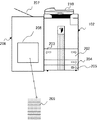
図1は、本発明の実施形態に係る印刷システムの概略構成を示す図である。 FIG. 1 is a diagram showing a schematic configuration of a printing system according to an embodiment of the present invention.
PC101は、ホストコンピュータ等の外部機器で、任意のアプリケーション等を実行して文書データを作成し、プリンタドライバにより印刷データを作成し、ネットワーク103を介して複合機(MFP)102に供給する。MFP(Multi Function Peripheral)102は、スキャン機能、印刷機能、送信機能、ボックス機能、ファクシミリ機能等を有する多機能処理装置である。
The PC 101 executes an arbitrary application or the like with an external device such as a host computer, creates document data, creates print data with a printer driver, and supplies the print data to the MFP (MFP) 102 via the
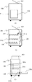
図2は、本実施形態に係るMFP102の概観図である。
FIG. 2 is an overview of the
このMFP102は、MFP102が印刷して排紙したシートを受け取り、積載して収容するスタッカ206と接続されている。またMFP102は、給紙デッキ202〜205を有し、それぞれMFP102が印刷するシートを積載して収容している。
The MFP 102 is connected to a
スタッカ206のサンプルトレイ部207は、MFP102で印刷されてスタッカ206に排紙されたシートを排出する場合に使用される。スタッカ206のスタック部208は、MFP102で印刷されたシートを大量に積載して収容できる。209は、スタック部208に積載されて排紙された用紙束を示す。スキャナ210はMFP102に設けられ、自動原稿送り機(ADF)に積載された原稿を搬送して読み取り、その原稿の画像データを出力する。
A
次に、図3〜図5を参照して、実施形態に係るスタッカ206の動作を説明する。
Next, the operation of the
図3は、実施形態に係るスタッカ206の構成を説明する図で、図3(A)は、スタッカ206の正面図、図3(B)は、スタッカ206を正面から見た断面図、図3(C)は図3(A)の矢印Aから見た断面図である。尚、図3において、前述の図2と共通する箇所は同じ番号で示している。
3A and 3B are diagrams illustrating the configuration of the
図3(B)で、リフトテーブル301は、MFP102から排紙されたシートを受け取って積載し、上下方向に移動することができる。尚、このリフトテーブル301は実際は1つであるが、上下方向に移動できるので、301aは最も上位の位置にある状態を示し301bは最も下降した状態を示している。イジェクトテーブル302は、リフトテーブル301に積載されたシート束を受け取ってスタッカ206の外に出すことができる。尚、イジェクトテーブル302は実際には1つであるが、図3(C)の左右方向に移動できるため、302bはスタッカ206の外に出た(イジェクトした)状態を示し、302aはスタッカ206内にある状態を示している。図3(B)で、シート搬送パス303は、MFP102から排紙されたシートがスタッカ206で搬送される搬送パスを示している。尚、本実施形態では、特に断りのない限りリフトテーブル301とイジェクトテーブル302とを合わせてスタッカ206のスタック部208と呼ぶ。
In FIG. 3B, the lift table 301 can receive and stack sheets discharged from the
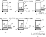
図4及び図5は、実施形態に係るスタッカ206にシートが積載されてスタッカ206の外にシート束をイジェクトするまでを説明する図である。尚、図4(A)〜(D)及び図5(A)〜(C)のそれぞれにおいて、左側は図3(B)に対応したスタッカ206の正面から見た断面図、右側は図3(C)に対応する図3(A)の矢印A側から見た断面図を示している。
FIG. 4 and FIG. 5 are diagrams for explaining a process from when a sheet is stacked on the
図4(A)は、スタッカ206のスタック部208(リフトテーブル301とイジェクトテーブル302)にシートが積載されていない状態を示しており、この状態では、リフトテーブル301とイジェクトテーブル302は本来の位置にある。
FIG. 4A shows a state in which sheets are not stacked on the stacking unit 208 (lift table 301 and eject table 302) of the
図4(B)は、リフトテーブル301にシート束401が積載された状態を示している。この状態で、リフトテーブル301は、シートが積載された量に応じて下降している。
FIG. 4B shows a state where the
図4(C)は、リフトテーブル301に積載されたシート量が最大に達してスタック部208が満載になった状態を示している。このときリフトテーブル301が降下して、イジェクトテーブル302の上にシート束402が載った状態である。これはリフトテーブル301の満載センサ(不図示)により、リフトテーブル301が満載と判定された場合に実施される。
FIG. 4C shows a state in which the amount of sheets stacked on the lift table 301 reaches the maximum and the
図4(D)は、イジェクトテーブル302をスタッカ206の外に移動させることにより、イジェクトテーブル302に積載されたシート束402をスタッカ206の外にイジェクした状態を示している。このときは、まだリフトテーブル301は下降した状態にある。
FIG. 4D shows a state in which the
図5(A)は、図4(D)でイジェクトテーブル302に積載されたシート束402をイジェクトした後、リフトテーブル301が上昇し、続いてMFP102から排紙されるシートをリフトテーブル301に積載している状態を示す。ここでは、シート束501は、継続してリフトテーブル301に積載されたシート束を示している。
5A, after ejecting the
図5(B)は、図5(A)の状態から、イジェクトテーブル302のシート束402をオペレータ(不図示)が手動で取り除いた状態を示す。つまり、イジェクトトレイ302上にシートが積載されていない状態である。
FIG. 5B shows a state in which an operator (not shown) has manually removed the
図5(C)は、図5(B)でイジェクトテーブル302に設置されているセンサ(不図示)により、イジェクトテーブル302上にシートが積載されていないことが検知されることにより、イジェクトテーブル302がスタッカ206の機内に収容される。それとともに、リフトテーブル301へのシートの積載が継続して実行されている状態を示す。シート束502は、リフトテーブル301に積載されたシート束を示す。
FIG. 5C illustrates that the ejection table 302 is detected when a sensor (not shown) installed on the ejection table 302 in FIG. 5B detects that no sheets are stacked on the ejection table 302. Is housed in the
上述した図4(A)〜図5(C)の動作を繰り返すことにより、MFP102からスタッカ206に連続して印刷済のシートを排紙して積載させることができる。
By repeating the operations shown in FIGS. 4A to 5C described above, printed sheets can be discharged from the
次に図6(A)〜(F)を参照して、実施形態に係るスタッカ206が指定部数スタックを実行するときの動作を説明する。ここで指定部数スタックとは、指定された部数分のシート束を1つのシート束として積載する機能を指すものとする。例えば、合計部数が10000部で、指定部数スタックが1000部と設定された場合には、1000部のシート束を一つの束としてスタッカ206のスタック部208に積載する。そして、合計10束のシート束(各シート束が1000部で構成される)が生成される。
Next, an operation when the
図6(A)〜(F)は、実施形態に係るスタッカ206による指定部数スタックの動作を説明する断面図である。ここでは図3(A)の矢印から見た断面図を示している。ここでは、部数指定がN部で、指定部数スタックがX部(N>X)に設定された場合を示している。
6A to 6F are cross-sectional views for explaining the operation of the designated number of stacks by the
図6(A)は、スタッカ206のスタック部(リフトテーブル301)208にシートが積載されていない状態を示している。
FIG. 6A shows a state where sheets are not stacked on the stack unit (lift table 301) 208 of the
図6(B)は、スタック部(リフトテーブル301)208に、N部のうちのX部のシートがリフトテーブル301の上に積載されている状態を示す。 FIG. 6B shows a state in which the X sheets of the N parts are stacked on the lift table 301 in the stack part (lift table 301) 208.
図6(C)は、X部のシート束601が積載されたので、指定部数イジェクトを指示し、イジェクトテーブル302がシート束601を積載した状態でスタッカ206の機外にイジェクトされた状態を示す。ここではリフトテーブル301の上にシートが積載されていない。
FIG. 6C shows a state in which the X number of sheet bundles 601 are stacked, so that the designated number of sheets are ejected, and the eject table 302 is ejected outside the
図6(D)は、図6(C)の状態からリフトテーブル301が最上位の位置に戻り、引き続きMFP102から排紙されるシートをリフトテーブル301に積載して、リフトテーブル301に次のX部のシート束602が積載された状態を示す。つまり、リフトテーブル301上に後続のX部のシート束が積載された状態を示す。
6D, the lift table 301 returns to the uppermost position from the state of FIG. 6C, and the sheets discharged from the
図6(E)は、図6(D)の状態から、イジェクトトレイ302に積載されていたシート束601をオペレータ(不図示)が手動で取り除いた状態を示す。
FIG. 6E shows a state in which an operator (not shown) manually removes the
図6(F)は、図6(E)の状態から、イジェクトテーブル302がスタッカ内に戻った状態を示している。これは、図6(E)で、イジェクトテーブル302に設置されているセンサ(不図示)によって、イジェクトテーブル302上にシート束が積載されていないことが検知された場合の動作である。図6(F)では、リフトテーブル301に積載されていたシート束602は、イジェクトテーブル302上に移動される。この状態から図6(C)に示すようにイジェクトテーブル302をタッカ206の機外にイジェクトすることにより、次のX部のシート束602が機外に出される。
FIG. 6 (F) shows a state where the eject table 302 has returned to the stacker from the state of FIG. 6 (E). This is an operation when it is detected in FIG. 6E that a sheet bundle is not stacked on the eject table 302 by a sensor (not shown) installed on the eject table 302. In FIG. 6F, the
こうして図6(C)〜(F)の動作を繰り返すことで、スタッカ206は、X部のシート束の単位でシート束をイジェクトする指定部数スタックを行うことができる。
By repeating the operations shown in FIGS. 6C to 6F, the
図7(A)〜(D)は、実施形態に係るスタッカ206におけるシート束の積載状態を説明する図である。ここでも、図3(A)の矢印から見た断面図を示している。
FIGS. 7A to 7D are diagrams illustrating the stacking state of the sheet bundle in the
図7(A)は、スタッカ206のスタック部のリフトテーブル301とイジェクトテーブル302にシートが積載されていない状態を示している。
FIG. 7A shows a state in which no sheets are stacked on the lift table 301 and the eject table 302 of the stack unit of the
図7(B)は、スタッカ206のイジェクトテーブル302にシート束701が積載されて、スタッカ206の外に出ている状態を示している。ここではリフトテーブル301はまだ下降した状態にある。この後、再びリフトテーブル301を最上位の位置に戻すことにより、MFP102から排紙されるシートを受け取って積載できるようになる。
FIG. 7B shows a state in which the
図7(C)は、リフトテーブル301にシート束702が積載されている状態を示している。この状態からイジェクトテーブル302をスタッカ206の外にイジェクトすることにより、リフトテーブル301はシートが積載されていない状態となる。そして、再びリフトテーブル301を最上位の位置に戻すと、MFP102から排紙されるシートをリフトテーブル301が受け取って積載することができる。
FIG. 7C shows a state where the
図7(D)は、リフトテーブル301とイジェクトテーブル302に、それぞれシート束703,704が積載されている状態を示している。この状態では、イジェクトテーブル302のシート束704が取り除かれない限り、MFP102から排紙されるシートを受け取って積載することができない。
FIG. 7D shows a state in which the sheet bundles 703 and 704 are stacked on the lift table 301 and the eject table 302, respectively. In this state, unless the
図8は、実施形態に係る印刷システムのPC101とMFP102の構成を示すブロック図である。
FIG. 8 is a block diagram illustrating configurations of the
ドキュメントデータ801は、PC101に格納されている文書データである。ここでいうドキュメントデータとは任意の文書作成アプリケーション(不図示)で作成されたデータである。プリンタドライバ802は、ドキュメントデータ801からPDL(Page Description Language)データの作成をする。ここでいうPDLとは、例えばPS,PCL,LIPS等のページ記述言語を示すものとする。もちろん、前述以外のページ記述言語であってもよい。記憶部803は、例えばHDD(ハードディスクドライブ)で、ドキュメントデータ801やプリンタドライバ802、及びドキュメントデータ801を作成するためのアプリケーション(不図示)等を格納している。通信インターフェイス804は、プリンタドライバ802が作成したPDLデータ(不図示)をネットワーク103を介して送信する。
次に実施形態に係るMFP102の構成を説明する。
Next, the configuration of the
制御部810はCPU811やRAM822を有し、このMFP102の動作を制御する。CPU811は、記憶部812に格納されているプログラムをRAM822に展開し、そのプログラムを実行することにより、このMFP102の動作を制御している。通信インターフェイス820は、PC101からネットワーク103を介して送信されてくるPDLデータ(不図示)等を受信する。データ受信部813は、通信インターフェイス820を介して受信したPDLデータ(不図示)を格納する。インタプリタ部815は、データ受信部813で受信したPDLデータ(不図示)を解析する。尚、インタプリタ部815は、前述のPS,PCL,LIPS等のPDLのフォーマットを解析できるものとする。もちろん、前述以外のフォーマットであってもよい。中間データ816は、データ受信部813が受信したPDLデータ(不図示)を、インタプリタ部815が解析して、変換したデータである。レンダラ部817は中間データ816を解析してイメージデータ(不図示)に変換する。イメージデータ記憶部818は、レンダラ部817の処理結果として得られるイメージデータ(不図示)を格納する。尚、本実施形態に係るデータ受信部813、インタプリタ部815、レンダラ部817の機能は、CPU811が上述のプログラムを実行することにより実現されるが、これらはそれぞれ単独のIC回路等で構成されていても良い。
A
プリンタエンジン819は、イメージデータ記憶部818に格納されているイメージデータ(不図示)からビデオ信号(不図示)に変換されたデータを受け取って印刷する。スキャナ821は、原稿(不図示)を読み取って、その原稿の画像に対応する画像データを出力する。尚、スキャナ821が読み取った画像はイメージデータ(不図示)としてイメージデータ記憶部818に格納される。記憶部812は、このMFP102の制御プログラムや、イメージデータ記憶部818に格納されているイメージデータ等も保存でき、更に各種印刷の設定情報(不図示)を保存するのにも使われる。操作部814は、タッチパネル機能を備えた表示部と、ユーザにより操作されるキー等を備えている。
The
またMFP102から排紙した印刷済のシートはスタッカ206に搬送されてスタッカ部208に積載される。ここでスタッカ206とMFP102とは制御線830で接続されており、制御部810のCPU811は、この制御線830を介して、スタッカ部208におけるシートの積載状態を知ることができる。またCPU811は、この制御線830を介してリフトテーブル301の上下移動、イジェクトテーブル302のイジェクト動作なども制御することができる。
A printed sheet discharged from the
次に、図9以降のフローチャートを用いて、本実施形態を説明する。 Next, this embodiment will be described with reference to the flowcharts of FIG.
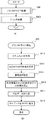
図9(A)は、実施形態に係る印刷システムの全体の処理の流れを説明するフローチャートである。この印刷システムは、図1に示すようにPC101とMFP102がネットワーク103を介して接続されており、PC101のプリンタドライバ802を介してMFP102にPDLデータを送信することにより、MFP102が印刷を行う。
FIG. 9A is a flowchart for explaining the overall processing flow of the printing system according to the embodiment. In this printing system, as shown in FIG. 1, a
S901は、PC101におけるプリンタドライバ802による印刷ジョブの生成処理である。このS901では、PC101のオペレータは、PC101で任意の文書作成アプリケーションを実行してドキュメントデータ801を生成する。そして、プリンタドライバ802は、ドキュメントデータ801からPDLデータ(不図示)を生成する。更にプリンタドライバ802は、ドキュメントデータ801を印刷する際に使用する各種設定を行い、そのPDLデータをネットワーク103を介してMFP102に送信する。尚、プリンタドライバ802によるS901の処理の詳細は、図9(B)のフローチャートを用いて説明する。
In step S <b> 901, print job generation processing is performed by the printer driver 802 in the
次にS902に進み、MFP102がPC101から送信される印刷ジョブを受信してプリンタ処理を実行する。この処理おいて、制御部810は、PDLデータを受信し、そのPDLデータをイメージデータに変換する。そして制御部810は、そのイメージデータをビデオ信号に変換してプリンタエンジン819に出力して印刷する。更に制御部810は、プリンタドライバ802の設定に従って、印刷済のシートをスタッカ206に排紙する。尚、S902のプリンタ処理の詳細についての説明は、図10(A)のフローチャートを参照して説明する。
In step S <b> 902, the
次に図9(B)のフローチャートを参照して、図9(A)のS901のプリンタドライバ処理について説明する。 Next, the printer driver processing in step S901 in FIG. 9A will be described with reference to the flowchart in FIG.
その前に図16のプリンタドライバのUI画面について説明する。 Before that, the UI screen of the printer driver in FIG. 16 will be described.
図16は、実施形態に係るPC101でプリンタドライバ802が表示するUI画面例を示す図である。
FIG. 16 is a diagram illustrating an example of a UI screen displayed by the printer driver 802 on the
タブ1601は、このUI画面が、「印刷設定」の画面であることを表示している。部数設定欄1603は、印刷する合計部数を設定する。この画面例では「10000部」が設定されている。尚、この部数設定欄1603の右側の▲▼を指示することにより、設定値を増減できる。用紙サイズの設定欄1603は、印刷に使用する用紙サイズを設定するのに使用される。この画面例では「A4」サイズが設定されている。尚、用紙サイズの設定欄1603の右側の▲▼を指示することにより、用紙サイズを変更することができる。排紙先指定の設定欄1604は、MFP102で印刷したシートをどこに排紙するかを指定するのに使用される。この画面例では「スタッカ1」(スタッカ206)が設定されている。尚、設定欄1604の右側の▲▼を指示することにより、他の排紙先を設定できる。ラジオボタン1605は、前述の指定部数スタックを有効にするか無効にするかを設定するのに使用される。この画面例では「ON」(指定部数スタックを有効)が選択されている。設定欄1606は、指定部数スタックの部数を設定する設定欄である。この画面例では「1000部」が設定されている。これにより、1000部をシート束を一束とする成果物(積載物)を生成するように指示できる。尚、設定欄1606の右側の▲▼を指示することにより、設定値を増減できる。
A
図9(B)に戻ってプリンタドライバ処理について説明する。 Returning to FIG. 9B, printer driver processing will be described.
先ずS910で、オペレータがPC101でアプリケーションを実行してドキュメントデータ801を生成する。次にS911に進みオペレータは、図16のUI画面で、印刷する合計の部数を設定する。図16の例では「10000部」が設定されている。これにより、10000部のシートが印刷される。次にS912に進みオペレータは、図16のUI画面で、スタッカ206を排紙先とした排紙先を設定する。これにより、MFP102で印刷されたシートはスタッカ206に送られてスタックされる。次にS913に進みオペレータは、図16のUI画面で、指定部数スタックを有効にするようにラジオボタン(ON)を選択する。またオペレータは、UI画面で、指定部数スタックの部数を設定する。図16の例では「1000部」が設定されている。これにより、1000部を一束とする成果物(積載物)を生成することができる。次にS914に進みプリンタドライバ802は、ドキュメントデータ801をPDLデータに変換し、S915でMFP102に送信する。尚、このときプリンタドライバ802は、S911で指定された部数、S912で指定された排紙先、S913で指定された指定部数スタックの設定と、指定部数スタックの部数をPDLデータに付加して送信する。
In step S <b> 910, the operator executes an application on the
次に、図10と図11を参照して、実施形態に係るMFP102によるプリンタ処理を説明する。
Next, printer processing by the
図10(A)は、図9(A)のS902のプリンタ処理の概略を示すフローチャートである。尚、この処理を実行するプログラムは記憶部812に記憶されており、実行時にCPU811によりRAM822に展開され、CPU811の制御の下に実行される。
FIG. 10A is a flowchart illustrating an outline of the printer process in S902 of FIG. Note that a program for executing this processing is stored in the
プリンタ処理を開始すると、まずS1000でCPU811は、ページ生成処理を行う。このページ生成処理では、PC101から受信したPDLデータをイメージデータに変換する。尚、このページ生成処理の詳細の説明は、図10(B)のフローチャートを参照して後述する。次にS1001に進みCPU811は、印刷処理を行う。この印刷処理では、S1000で生成したイメージデータをビデオデータに変換してプリンタエンジン819に転送して印刷させる。尚、この印刷処理の詳細の説明は、図11のフローチャートを参照して後述する。
When the printer process is started, first, in step S1000, the
図10(B)は、図10(A)のS1000のページ生成処理を説明するフローチャートである。 FIG. 10B is a flowchart for explaining the page generation processing in S1000 of FIG.
まずS1010でCPU811は、PC101から送信されたPDLデータを受信する。次にS1011に進みCPU811は、その受信したPDLデータを解析する。これはインタプリタ815の機能に該当する。次にS1012でCPU811は、インタプリタ815により解析した印刷データを中間データ816に変換する。この中間データ816とは、「ビットマップ」、「ランレングス」、「台形」、「ボックス」、及び「高速境界符合化されたビットマップ」等の描画オブジェクトと背景パターン、及び、それらをラスタメモリに描画する際の描画論理の総称を指すものとする。このときCPU811は、PDLデータに、部数の設定、排紙先設定、指定部数スタック設定とその部数の設定情報が付加されている場合には、それらを記憶部812に格納する。そしてS1013に進みCPU811は、中間データ816をレンダリングする。これはレンダラ817の機能に該当する。ここでいうレンダリングは、中間データ816をレンダラ部817を用いてイメージデータに変換してイメージデータ記憶部818に格納することを指すものとする。
First, in step S1010, the
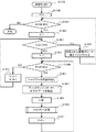
図11は、図10(A)のS1001の印刷処理を説明するフローチャートである。 FIG. 11 is a flowchart for explaining the printing process in S1001 of FIG.
先ずS1100でCPU811は、記憶部812に記憶されている情報を参照して、指定部数スタックの指定部数(X)が設定されているかどうかを判定する。ここでCPU811は、記憶部812から読み出した値(X)がX=0であれば指定部数スタックが設定されていないと判定してS1101の排紙処理1を実行して、この処理を終了する。尚、S1101の排紙処理1では、シートに印刷し、その印刷したシートをスタッカ206に排紙してスタック部208に積載する処理を行う。尚、排紙処理1の詳細は図12のフローチャートを参照して後述する。
First, in step S <b> 1100, the
一方、S1100でCPU811は、記憶部812から読み出した値(X)が「0」でなければ指定部数スタックが設定されていると判定してS1102に進んでイジェクト処理を実行する。このイジェクト処理では、CPU811は、スタッカ206のスタック部208のリフトテーブル301に既にシートが存在しているかどうかを判定する。その結果、リフトテーブル301にシートが存在していると判定した場合には、そのシートをイジェクトテーブル302に移してスタッカ206の外にイジェクトする処理を行う。これは、指定部数スタックを実施したシートと、先行のジョブが積載したシートとの混載を防ぐためである。尚、イジェクト処理の詳細は図13のフローチャートを参照して後述する。次にS1103に進みCPU811は、排紙処理2の処理を行う。この処理でCPU811は、スタッカ206に指定部数ごとに、印刷済のシートを排紙する処理を実行して、この処理を終了する。尚、排紙処理2の詳細は図14のフローチャートを参照して後述する。
On the other hand, in S1100, if the value (X) read from the
尚、図11のフローチャートでは、指定部数スタックが指定されているときにS1102でイジェクト処理を実行しているが本発明はこれに限定されない。即ち、指定部数スタックが指定されていない通常の印刷ジョブの場合も、別のジョブで印刷されたシートを除去するためにS1102を実行するようにしても良い。 In the flowchart of FIG. 11, the eject process is executed in S1102 when the designated number of stacks is designated, but the present invention is not limited to this. That is, even in the case of a normal print job in which the designated number of copies stack is not designated, S1102 may be executed to remove a sheet printed in another job.
図12は、図11のS1101の排紙処理1を説明するフローチャートである。
FIG. 12 is a flowchart for explaining the
先ずS1200でCPU811は、処理中の部数を示す変数Nを「1」に初期化する。尚、Nは、N≧1を満たす整数値とする。変数Nは、RAM822に格納されている。次にS1201に進みCPU811は、変数Nが総部数(N_MAX)以下かどうかを判定する。ここで変数NがN_MAXを超えていればこの処理を終了するが、変数Nが総部数(N_MAX)以下であれば、まだ全ての部数の印刷処理が終了していないと判定してS1202に進む。
In step S1200, the
S1202でCPU811は処理中のページ数を示す変数Pを「1」に初期化する。尚、Pは、P≧1を満たす整数値とする。この変数PもRAM822に格納されている。次にS1203に進みCPU811は、変数Pが、一つの部の総ページ数(P_MAX)(即ち、受信した印刷ジョブに含まれる総ページ数)を超えているかどうかを判定する。ここで変数PがP_MAX以下であれば、まだ印刷すべきページがあると判定してS1204に進むが、変数PがP_MAXを超えている場合には、一つの部の処理が完了したと判定してS1209に進む。S1209でCPU811は変数Nを+1してS1201に進む。
In step S1202, the
S1204でCPU811は、イメージデータ記憶部818から処理中のページ(P)のイメージデータを読み出してS1205に進む。S1205でCPU811は、そのイメージデータをビデオデータに変換してプリンタエンジン819に出力する。そしてS1206に進みCPU811は、MFP102の給紙部からシートを給紙し、そのシートにビデオデータを用いて印刷する。そしてS1207に進みCPU811は、印刷したシートをスタッカ206に排紙する。尚、スタッカ206への排紙処理の詳細な説明は、図15を参照して後述する。次にS1208に進みCPU811は、変数Pを+1してS1203に進む。
In step S1204, the
尚、総部数(N_MAX)は、前述の図16の例では「10000」となる。また総ページ数(P_MAX)は、受信した印刷ジョブに含まれるイメージデータの総ページ数であり、これらはいずれもRAM822に記憶されている。
The total number of copies (N_MAX) is “10000” in the example of FIG. The total number of pages (P_MAX) is the total number of pages of image data included in the received print job, and these are all stored in the
この図12に示す処理によれば、受信した印刷ジョブに含まれるページを、指定された部数だけ印刷してスタッカ206に排紙する、周知の印刷及び排紙処理が実行される。
According to the processing shown in FIG. 12, well-known printing and paper discharge processing is executed in which the pages included in the received print job are printed in the designated number of copies and discharged to the
次に図13を参照して、図11のS1102のイジェクト処理を説明する。 Next, the ejection processing in S1102 of FIG. 11 will be described with reference to FIG.
図13は、図11のS1102のイジェクト処理を説明するフローチャートである。 FIG. 13 is a flowchart for explaining the ejection processing in S1102 of FIG.
まずS1300でCPU811は、スタッカ206に装備されている積載センサからの信号により、スタック部208にシートが積載されているかどうかを判定する。これは、これから実行する印刷ジョブ(指定部数スタックを行うジョブ)よりも前のジョブで印刷されたシートがスタック部208に残っていると、指定部数スタックが正常に実行されなくなるためである。例えば、スタッカ206におけるシートの積載状態が図7(A)(B)の状態であれば、CPU811は、スタック部208にシートが積載されていない状態であると判定する。この場合、CPU811はイジェクト処理が不要であると判定してこの処理を終了する。一方、図7(C)(D)の状態であれば、印刷ジョブがそのまま実行されると、この印刷ジョブで印刷されたシートと先行のジョブで印刷されたシートとが混載してしまう。よって、この場合CPU811は、イジェクト処理が必要と判定してS1301に処理を進める。
First, in step S <b> 1300, the
S1301でCPU811は、スタッカ206のスタック部208でイジェクト動作が可能な状態であるか否かを判定する。ここでもし、スタック部208の状態が図7(D)状態である場合はイジェクト動作が不可能と判定してS1302に進む。S1302でCPU811は、操作部814にエラーメッセージを表示してこの処理を終了する。具体的には、S1302でCPU811は、操作部814の表示部にスタッカ206のスタック部208のイジェクトテーブル302上のシートを取り除く必要がある旨の所定のメッセージを表示してユーザに通知する。この場合、オペレータがイジェクトテーブル302上のシートを取り除くとスタック部208の状態は図7(C)の状態に移行する。これによりスタッカ206のスタック部208のリフトテーブル301に載置されているシートをイジェクトテーブル302によりスタッカ206の外に出すことができる状態になる。
In step S1301, the
一方S1301でCPU811は、スタック部208の状態が、例えば図7(C)状態であると判定して場合は、イジェクト動作が可能と判定してS1303に処理を進める。S1303でCPU811は、スタッカ206のイジェクトテーブル302を機外にイジェクトさせることにより、図7(C)に示す状態から図7(B)に示す状態に移行させる。これにより、これら実行する印刷ジョブにより印刷されたシートと、先行ジョブで印刷されたシートとの混載を避けることができる。
On the other hand, if the
次に、図14を参照して、排紙処理2について説明する。 Next, the paper discharge process 2 will be described with reference to FIG.
図14は、図11のS1103の排紙処理2を説明するフローチャートである。 FIG. 14 is a flowchart for explaining the paper discharge process 2 in S1103 of FIG.
先ずS1400でCPU811は、処理中の部数を示す変数Nを「1」に初期化する。尚、Nは、N≧1を満たす整数値とする。変数Nは、RAM822に格納されている。次にS1401に進みCPU811は、変数Nが総部数(N_MAX)以下かどうかを判定する。ここで変数NがN_MAXを超えていればこの処理を終了するが、変数Nが総部数(N_MAX)以下であれば、まだ全ての部数の印刷処理が終了していないと判定してS1402に進む。S1402でCPU811は、指定部数スタックを処理中の部数を示す変数Xを「1」に初期化する。尚、Xは、X≧1,N>Xを満たす整数値とする。次にS1403に進みCPU811は、変数Xが、指定部数スタックする部数を示す変数(X_MAX)を超えているかどうか判定する。ここで変数Xが(X_MAX)を超えていない場合は、CPU811は、指定された部数がスタックされていないと判定してS1405に進む。一方、S1403でCPU811が、変数Xが(X_MAX)を超えていると判定したときはS1404に進む。S1404では、スタッカ206のスタック部208は、指定された部数(X_MAX)のシートが積載された状態になっている。よって、CPU811は、イジェクトテーブル302をスタッカ206の外にイジェクトさせてS1401に進む。
In step S1400, the
尚、総部数(N_MAX)は、前述の図16の例では「10000」となる。また(X_MAX)は、前述の図16の例では「1000」となり、これらはいずれもRAM822に記憶されている。
The total number of copies (N_MAX) is “10000” in the example of FIG. Further, (X_MAX) is “1000” in the example of FIG. 16 described above, and these are all stored in the
S1405〜S1411の処理は、前述の図12のS1202〜S1208の処理と同じであるため、その説明を省略する。 The processing of S1405 to S1411 is the same as the processing of S1202 to S1208 of FIG.
S1406でCPU811は、変数Pが、総ページ数(P_MAX)を超えていると判定するとS1412に進みCPU811は、処理中の指定部数スタックの部数を示す変数Xを+1し、処理中の部数を示す変数Nも+1してS1403に処理を進める。尚、ここで総ページ数(P_MAX)は、受信した印刷ジョブに含まれるイメージデータの総ページ数でありRAM822に記憶されている。
If the
この図14に示す処理によれば、例えば図16に示すような指定部数スタックが指定されると、1000部のシート束がイジェクトテーブル302上に積載される度にS1404の処理が実行されることになる。これによりオペレータは、イジェクトテーブル302上に積載された1000部のシート束をイジェクトテーブル302から取り出して梱包することにより、指定した部数のシート束を1つのシート束として取り出すことができる。尚、図16の例では、オペレータは、イジェクトテーブル302上に積載された1000部のシート束を10回取り出すことにより、目的とする全てのシート束を得ることができる。
According to the process shown in FIG. 14, for example, when a designated number of stacks as shown in FIG. 16 is designated, the process of S1404 is executed each
図15は、図12のS1207、図14のS1410のスタッカ206への排紙処理を説明するフローチャートである。
FIG. 15 is a flowchart for explaining the discharge process to the
先ずS1500でCPU811は、スタッカ206のスタック部208への排紙が可能かどうかを判定する。このときCPU811は、スタック部208のセンサからの信号に基づいて、スタック部208が満載状態かどうかを判定する。S1500でCPU811が、スタック部208が満載状態でないと判定した場合はS1504に処理を進め、MFP102で印刷したシートをスタッカ206に排紙して、この処理を終了する。
First, in step S <b> 1500, the
一方、S1500でスタック部208が満載状態であると判定したときはS1501に処理を進め、CPU811は、スタック部208のイジェクトテーブル302により、積載しているシートをスタッカ206の外にイジェクト可能かどうかを判定する。ここで可能と判定するとS1503に進み、CPU811は、スタッカ206のスタック部208のイジェクトテーブル302をイジェクトさせる。これによって、スタック部208のリフトテーブル301にシートが積載されていない状態となって、スタッカ206が受け取ったシートをリフトテーブル301に積載できるようになる。こうしてS1504に進みMFP102で印刷したシートをスタッカ206に排紙して、この処理を終了する。
On the other hand, if it is determined in S1500 that the
一方、S1501で、イジェクトテーブル302により、積載しているシートをスタッカ206の外にイジェクトできないと判定したときはS1502に進む。S1502でCPU811は、操作部814の表示部に、スタッカ206のスタック部208のイジェクトテーブル302上のシートを取り除く必要がある旨のメッセージを表示してS1501に進む。この場合、オペレータは、イジェクトテーブル302上のシートを取り除くことでイジェクト可能な状態にすることができる。
On the other hand, if it is determined in step S1501 that the eject table 302 cannot eject the stacked sheets outside the
尚、上述の実施形態では、印刷装置であるMFP102と、シートの積載装置であるスタッカ206とが別体の場合で説明したが、MFP102とスタッカ206とが一体となった印刷装置であっても良い。
In the above-described embodiment, the
(その他の実施形態)
また、本発明は、以下の処理を実行することによっても実現される。即ち、上述した実施形態の機能を実現するソフトウェア(プログラム)を、ネットワーク又は各種記憶媒体を介してシステム或いは装置に供給し、そのシステム或いは装置のコンピュータ(又はCPUやMPU等)がプログラムを読み出して実行する処理である。
(Other embodiments)
The present invention can also be realized by executing the following processing. That is, software (program) that realizes the functions of the above-described embodiments is supplied to a system or apparatus via a network or various storage media, and a computer (or CPU, MPU, etc.) of the system or apparatus reads the program. It is a process to be executed.
本発明は上記実施の形態に制限されるものではなく、本発明の精神及び範囲から離脱することなく、様々な変更及び変形が可能である。従って、本発明の範囲を公にするために、以下の請求項を添付する。 The present invention is not limited to the above-described embodiment, and various changes and modifications can be made without departing from the spirit and scope of the present invention. Therefore, in order to make the scope of the present invention public, the following claims are attached.
101…PC(ホストコンピュータ)、102…MFP(Multi Function Peripheral)、206…スタッカ、208…スタック部、301…リフトテーブル、302…イジェクトテーブル,811…CPU,822…RAM。
DESCRIPTION OF
Claims (9)
前記印刷手段により印刷されたシートを受け取って積載するとともに、積載されたシートを、オペレータが取り出し可能にイジェクト可能な積載手段と、
前記積載手段にシートが積載されているか否かを判定する判定手段と、
指定された部数分のシートが前記積載手段に積載される度に、当該積載されたシートをイジェクトするように設定する設定手段と、
印刷ジョブに対して前記設定手段による設定がなされ、且つ、前記判定手段により前記積載手段にシートが積載されていると判定されると、当該積載されているシートを前記印刷ジョブの実行を開始するときにイジェクトするように制御する制御手段と、
を有することを特徴とする印刷装置。 Printing means for printing on a sheet according to a print job;
Receiving and stacking sheets printed by the printing means, and stacking means capable of ejecting the stacked sheets so that an operator can take them out;
Determination means for determining whether or not a sheet is stacked on the stacking means;
Setting means for setting the ejected sheets each time the designated number of sheets are stacked on the stacking means;
When the setting by the setting unit is made for the print job and the determination unit determines that the sheets are stacked on the stacking unit, the execution of the print job is started for the stacked sheets. Control means to control to eject at times,
A printing apparatus comprising:
前記印刷手段により印刷されたシートを受け取って積載するリフトテーブルと、
前記リフトテーブルに積載されたシートを受け取って前記印刷装置の外にイジェクトするイジェクトテーブルとを有することを特徴とする請求項1に記載の印刷装置。 The loading means is
A lift table for receiving and stacking sheets printed by the printing means;
The printing apparatus according to claim 1, further comprising: an ejection table that receives sheets stacked on the lift table and ejects the sheets to the outside of the printing apparatus.
前記ホストコンピュータは、
指定された部数分のシートが積載される度に、当該積載されたシートをイジェクトするように設定する設定手段を有し、
前記印刷装置は、
前記ホストコンピュータから送信された印刷ジョブを受信する受信手段と、
前記スタッカにシートが積載されているかどうかを判定する判定手段と、
印刷ジョブに対して前記設定手段による設定がなされ、且つ、前記判定手段により前記スタッカにシートが積載されていると判定されると、当該積載されているシートを前記印刷ジョブの実行を開始するときにイジェクトするように制御する制御手段と、を有し、
前記スタッカは、
前記印刷手段により印刷されたシートを受け取って積載するリフトテーブルと、
前記リフトテーブルに積載されたシートを受け取って前記スタッカの外にイジェクトするイジェクトテーブルと、を有し、
前記制御手段は、前記リフトテーブルにシートが積載されているとき、当該リフトテーブルに積載されたシートを前記イジェクトテーブルにより前記スタッカの外に出すように制御することを特徴とする印刷システム。 A printing system having a host computer, a printing apparatus, and a stacker that receives and stacks sheets printed by the printing apparatus,
The host computer
A setting unit configured to eject the stacked sheets every time the designated number of sheets are stacked;
The printing apparatus includes:
Receiving means for receiving a print job transmitted from the host computer;
Determination means for determining whether or not a sheet is stacked on the stacker;
When the setting by the setting unit is made for the print job and the determination unit determines that the sheet is stacked on the stacker, the execution of the print job is started for the stacked sheet. And control means for controlling to eject to
The stacker is
A lift table for receiving and stacking sheets printed by the printing means;
An eject table that receives the sheets stacked on the lift table and ejects the sheets out of the stacker;
The control system is configured to control so that, when a sheet is stacked on the lift table, the sheet stacked on the lift table is ejected from the stacker by the eject table.
印刷ジョブに従ってシートに印刷する印刷工程と、
前記印刷工程で印刷されたシートを受け取って積載するとともに、積載されたシートを、オペレータが取り出し可能にイジェクト可能なスタッカに、前記印刷工程で印刷されたシートを排出して積載する積載工程と、
前記スタッカにシートが積載されているか否かを判定する判定工程と、
指定された部数分のシートが前記積載工程で積載される度に、当該積載されたシートをイジェクトするように設定する設定工程と、
印刷ジョブに対して前記設定工程における設定がなされ、且つ、前記判定工程で前記スタッカにシートが積載されていると判定されると、当該積載されているシートを前記印刷ジョブの実行を開始するときにイジェクトするように制御する制御工程と、
を有することを特徴とする印刷装置の制御方法。 A control method for controlling a printing apparatus,
A printing process for printing on a sheet according to a print job;
A stacking process for receiving and stacking sheets printed in the printing process, and discharging and stacking the stacked sheets on a stacker that can be ejected by an operator.
A determination step of determining whether or not a sheet is stacked on the stacker;
A setting process for setting the ejected sheets each time the designated number of sheets are stacked in the stacking process;
When the print job is set in the setting step and the determination step determines that sheets are stacked on the stacker, the execution of the print job is started for the stacked sheets. A control process for controlling to eject
A control method for a printing apparatus, comprising:
Priority Applications (3)
| Application Number | Priority Date | Filing Date | Title |
|---|---|---|---|
| JP2014159767A JP2016037333A (en) | 2014-08-05 | 2014-08-05 | Printing system and printer, and control method and program of the same |
| US14/809,146 US20160044194A1 (en) | 2014-08-05 | 2015-07-24 | Printing apparatus, method of controlling the same, and storage medium |
| CN201510462964.2A CN105329001A (en) | 2014-08-05 | 2015-07-31 | Printing apparatus and method of controlling the same |
Applications Claiming Priority (1)
| Application Number | Priority Date | Filing Date | Title |
|---|---|---|---|
| JP2014159767A JP2016037333A (en) | 2014-08-05 | 2014-08-05 | Printing system and printer, and control method and program of the same |
Publications (2)
| Publication Number | Publication Date |
|---|---|
| JP2016037333A true JP2016037333A (en) | 2016-03-22 |
| JP2016037333A5 JP2016037333A5 (en) | 2017-09-14 |
Family
ID=55268371
Family Applications (1)
| Application Number | Title | Priority Date | Filing Date |
|---|---|---|---|
| JP2014159767A Pending JP2016037333A (en) | 2014-08-05 | 2014-08-05 | Printing system and printer, and control method and program of the same |
Country Status (3)
| Country | Link |
|---|---|
| US (1) | US20160044194A1 (en) |
| JP (1) | JP2016037333A (en) |
| CN (1) | CN105329001A (en) |
Cited By (4)
| Publication number | Priority date | Publication date | Assignee | Title |
|---|---|---|---|---|
| JP2019142689A (en) * | 2018-02-23 | 2019-08-29 | コニカミノルタ株式会社 | Paper loading device and image formation system |
| JP2020172383A (en) * | 2019-04-12 | 2020-10-22 | コニカミノルタ株式会社 | Stacker and image formation device |
| JP2020203735A (en) * | 2019-06-14 | 2020-12-24 | コニカミノルタ株式会社 | Image forming system, sheet loading device and sheet loading method |
| JP2021098581A (en) * | 2019-12-23 | 2021-07-01 | コニカミノルタ株式会社 | Image forming system and method of discharge |
Families Citing this family (3)
| Publication number | Priority date | Publication date | Assignee | Title |
|---|---|---|---|---|
| JP2016046605A (en) * | 2014-08-20 | 2016-04-04 | キヤノン株式会社 | Printer and control method |
| WO2017180165A1 (en) * | 2016-04-15 | 2017-10-19 | Hewlett-Packard Development Company, L.P. | Printing device with wireless-network module |
| JP2019119178A (en) * | 2018-01-10 | 2019-07-22 | キヤノン株式会社 | Image forming apparatus, information processing terminal and computer program |
Citations (7)
| Publication number | Priority date | Publication date | Assignee | Title |
|---|---|---|---|---|
| JPH10194551A (en) * | 1997-01-10 | 1998-07-28 | Canon Inc | Image forming device |
| JP2001122501A (en) * | 1999-10-21 | 2001-05-08 | Minolta Co Ltd | Image forming device |
| JP2005200109A (en) * | 2004-01-13 | 2005-07-28 | Konica Minolta Business Technologies Inc | Image forming device |
| JP2009300913A (en) * | 2008-06-17 | 2009-12-24 | Konica Minolta Business Technologies Inc | Image forming system |
| US20140139857A1 (en) * | 2012-11-22 | 2014-05-22 | Canon Kabushiki Kaisha | Information processing apparatus, printing apparatus, method for controlling information processing apparatus, and method for controlling printing apparatus |
| JP2014109746A (en) * | 2012-12-04 | 2014-06-12 | Canon Inc | Image processing apparatus and control method thereof |
| US20140159306A1 (en) * | 2012-12-07 | 2014-06-12 | Canon Kabushiki Kaisha | Sheet stacking system and method of controlling the same, and storage medium |
Family Cites Families (5)
| Publication number | Priority date | Publication date | Assignee | Title |
|---|---|---|---|---|
| US7686296B2 (en) * | 2004-09-22 | 2010-03-30 | Sharp Kabushiki Kaisha | Sheet stacking device and image forming apparatus including the same |
| JP5219779B2 (en) * | 2008-12-18 | 2013-06-26 | キヤノン株式会社 | Sheet processing apparatus, sheet processing apparatus control method, storage medium, and program |
| JP5574625B2 (en) * | 2009-05-28 | 2014-08-20 | キヤノン株式会社 | Information processing apparatus, control method for external apparatus, and control program |
| JP5793928B2 (en) * | 2010-06-25 | 2015-10-14 | 株式会社リコー | Paper discharge device, full detection method and program |
| JP5643585B2 (en) * | 2010-09-14 | 2014-12-17 | キヤノン株式会社 | Printing apparatus, printing apparatus control method, and program |
-
2014
- 2014-08-05 JP JP2014159767A patent/JP2016037333A/en active Pending
-
2015
- 2015-07-24 US US14/809,146 patent/US20160044194A1/en not_active Abandoned
- 2015-07-31 CN CN201510462964.2A patent/CN105329001A/en active Pending
Patent Citations (9)
| Publication number | Priority date | Publication date | Assignee | Title |
|---|---|---|---|---|
| JPH10194551A (en) * | 1997-01-10 | 1998-07-28 | Canon Inc | Image forming device |
| JP2001122501A (en) * | 1999-10-21 | 2001-05-08 | Minolta Co Ltd | Image forming device |
| JP2005200109A (en) * | 2004-01-13 | 2005-07-28 | Konica Minolta Business Technologies Inc | Image forming device |
| JP2009300913A (en) * | 2008-06-17 | 2009-12-24 | Konica Minolta Business Technologies Inc | Image forming system |
| US20140139857A1 (en) * | 2012-11-22 | 2014-05-22 | Canon Kabushiki Kaisha | Information processing apparatus, printing apparatus, method for controlling information processing apparatus, and method for controlling printing apparatus |
| JP2014106553A (en) * | 2012-11-22 | 2014-06-09 | Canon Inc | Information processing device, printing apparatus, printing system, job processing method for information processing device, control method for printing apparatus, and program |
| JP2014109746A (en) * | 2012-12-04 | 2014-06-12 | Canon Inc | Image processing apparatus and control method thereof |
| US20140159306A1 (en) * | 2012-12-07 | 2014-06-12 | Canon Kabushiki Kaisha | Sheet stacking system and method of controlling the same, and storage medium |
| JP2014114109A (en) * | 2012-12-07 | 2014-06-26 | Canon Inc | Printing system, printing system control system, and program |
Cited By (6)
| Publication number | Priority date | Publication date | Assignee | Title |
|---|---|---|---|---|
| JP2019142689A (en) * | 2018-02-23 | 2019-08-29 | コニカミノルタ株式会社 | Paper loading device and image formation system |
| JP2020172383A (en) * | 2019-04-12 | 2020-10-22 | コニカミノルタ株式会社 | Stacker and image formation device |
| JP7159957B2 (en) | 2019-04-12 | 2022-10-25 | コニカミノルタ株式会社 | Stacker and image forming device |
| JP2020203735A (en) * | 2019-06-14 | 2020-12-24 | コニカミノルタ株式会社 | Image forming system, sheet loading device and sheet loading method |
| JP2021098581A (en) * | 2019-12-23 | 2021-07-01 | コニカミノルタ株式会社 | Image forming system and method of discharge |
| JP7409071B2 (en) | 2019-12-23 | 2024-01-09 | コニカミノルタ株式会社 | Image forming system and discharge method |
Also Published As
| Publication number | Publication date |
|---|---|
| US20160044194A1 (en) | 2016-02-11 |
| CN105329001A (en) | 2016-02-17 |
Similar Documents
| Publication | Publication Date | Title |
|---|---|---|
| JP2016037333A (en) | Printing system and printer, and control method and program of the same | |
| KR20100129193A (en) | Information processing apparatus, method for controlling the information processing apparatus, and a computer-readable storage medium | |
| US9102173B2 (en) | Print processing apparatus, control method, and storage medium | |
| US9681010B2 (en) | Printing apparatus for controlling discharge to first stacking unit according to status of first stacking unit and second stacking unit | |
| JP2013162422A (en) | Image forming device, control method of the same, and program | |
| JP6553946B2 (en) | PRINT CONTROL SYSTEM, PRINT CONTROL DEVICE, PRINT CONTROL METHOD, AND PROGRAM | |
| US20160070223A1 (en) | Printing apparatus, printing method, storage medium for storing program, and printing system | |
| US10606524B2 (en) | Image forming apparatus, image forming system, information processing apparatus, control method for an information processing apparatus, and non-transitory computer-readable storage medium with determination of mounted punch die | |
| JP5643585B2 (en) | Printing apparatus, printing apparatus control method, and program | |
| US10185527B2 (en) | Printed system, image display apparatus, image display method, and non-transitory computer readable medium | |
| JP2010005790A (en) | Image forming system | |
| JP6235774B2 (en) | Printing apparatus and control method and program therefor | |
| JP2007261732A (en) | Image forming system and program | |
| JP5503434B2 (en) | Printing apparatus, printing apparatus control method, and program | |
| JP2007197206A (en) | Printer and printing method | |
| JP2016099763A (en) | Print job management device, management method, and program | |
| JP5084675B2 (en) | Information processing apparatus, control method, computer program, storage medium | |
| JP7039961B2 (en) | Information control devices, printing systems and programs | |
| JP6996118B2 (en) | Information processing equipment and programs | |
| US9292774B2 (en) | Image forming apparatus, image forming method | |
| US8873082B2 (en) | Printing apparatus, printing control method, and storage medium for controlling printing performed by variable data printing | |
| JP7286942B2 (en) | Image forming system and program | |
| US20160297214A1 (en) | Method of controlling discharge of printed sheets as sheet bundle, sheet discharge control apparatus, and storage medium | |
| US20230205465A1 (en) | Control method of information processing apparatus, information processing apparatus, and storage medium | |
| JP2018008511A (en) | Information processing device, information processing system, information processing method, and program |
Legal Events
| Date | Code | Title | Description |
|---|---|---|---|
| A521 | Request for written amendment filed |
Free format text: JAPANESE INTERMEDIATE CODE: A523 Effective date: 20170803 |
|
| A621 | Written request for application examination |
Free format text: JAPANESE INTERMEDIATE CODE: A621 Effective date: 20170803 |
|
| A977 | Report on retrieval |
Free format text: JAPANESE INTERMEDIATE CODE: A971007 Effective date: 20180420 |
|
| A131 | Notification of reasons for refusal |
Free format text: JAPANESE INTERMEDIATE CODE: A131 Effective date: 20180518 |
|
| A02 | Decision of refusal |
Free format text: JAPANESE INTERMEDIATE CODE: A02 Effective date: 20181119 |