JP2016031446A - Imaging device and method of controlling the same - Google Patents
Imaging device and method of controlling the same Download PDFInfo
- Publication number
- JP2016031446A JP2016031446A JP2014153464A JP2014153464A JP2016031446A JP 2016031446 A JP2016031446 A JP 2016031446A JP 2014153464 A JP2014153464 A JP 2014153464A JP 2014153464 A JP2014153464 A JP 2014153464A JP 2016031446 A JP2016031446 A JP 2016031446A
- Authority
- JP
- Japan
- Prior art keywords
- pixel
- focus detection
- imaging
- exposure
- signal
- Prior art date
- Legal status (The legal status is an assumption and is not a legal conclusion. Google has not performed a legal analysis and makes no representation as to the accuracy of the status listed.)
- Pending
Links
Images


Abstract
Description
本発明は、焦点検出画素及び撮像画素を有する撮像素子の信号処理に関し、特に焦点検出信号を得るための演算処理に関するものである。 The present invention relates to signal processing of an image sensor having a focus detection pixel and an imaging pixel, and more particularly to arithmetic processing for obtaining a focus detection signal.
瞳分割位相差方式の焦点検出では、撮影レンズの通過光束を分割した一対の瞳分割像を用いる。この一対の瞳分割像の像ズレを検出することによって、撮影レンズのデフォーカス量とデフォーカス方向を検出できる。この原理に従い、撮像素子の画素に遮光層を形成した焦点検出用画素を備える固体撮像素子がある。特許文献1では、通常画素の間に焦点検出画素が埋め込まれた固体撮像素子を用いて、瞳分割位相差方式の焦点検出を行う方法が開示されている。 In focus detection using the pupil division phase difference method, a pair of pupil division images obtained by dividing the light beam passing through the photographing lens is used. By detecting an image shift between the pair of pupil divided images, the defocus amount and the defocus direction of the photographing lens can be detected. In accordance with this principle, there is a solid-state image sensor including a focus detection pixel in which a light shielding layer is formed on a pixel of the image sensor. Patent Document 1 discloses a method of performing pupil division phase difference type focus detection using a solid-state imaging device in which focus detection pixels are embedded between normal pixels.
特許文献1に開示の技術では、焦点検出画素の位置にて撮像画素が欠落することになるため、周囲の撮像画素から補間して画像を生成する必要がある。そのため、全画素数に対して焦点検出画素数の占める割合が高いほど、画質低下が起こり易くなる。画質低下を抑えるために、撮像面上にて焦点検出画素の分布密度(または配置密度)を下げたのでは、焦点検出精度が低下してしまう。そこで、本発明の目的は、撮像素子にて焦点検出画素の分布密度が低い場合でも、焦点検出精度の低下を抑えられる焦点検出信号の演算処理を提供することである。 In the technique disclosed in Patent Document 1, since an imaging pixel is lost at the position of the focus detection pixel, it is necessary to generate an image by interpolating from surrounding imaging pixels. For this reason, the higher the ratio of the number of focus detection pixels to the total number of pixels, the easier it is for image quality degradation to occur. If the distribution density (or arrangement density) of the focus detection pixels is lowered on the imaging surface in order to suppress the deterioration of the image quality, the focus detection accuracy is lowered. Therefore, an object of the present invention is to provide a calculation process of a focus detection signal that can suppress a decrease in focus detection accuracy even when the distribution density of focus detection pixels is low in an image sensor.
本発明に係る装置は、撮像光学系を構成する焦点調節レンズと、マイクロレンズをそれぞれ通した光を受光する焦点検出画素及び撮像画素を有する撮像素子とを備える撮像装置であって、前記焦点調節レンズの駆動手段と、前記撮像画素の画素値及び前記焦点検出画素の画素値から焦点検出信号を演算する演算手段を備える。前記演算手段は、前記焦点調節レンズを通した第1露光によって前記焦点検出画素及び撮像画素からそれぞれ出力される第1の画素信号と、前記駆動手段が前記焦点調節レンズを前記第1露光での位置から光軸方向に移動させた第2露光によって前記焦点検出画素及び撮像画素からそれぞれ出力される第2の画素信号を取得し、前記焦点検出画素の間に配置された前記撮像画素の光電変換部が複数に分割された領域から構成されるとした場合にそれぞれの領域で得られる画素信号を算出することにより、当該撮像画素の画素値及び前記焦点検出画素の画素値から焦点検出信号を演算する。 An apparatus according to the present invention is an image pickup apparatus including a focus adjustment lens constituting an image pickup optical system, a focus detection pixel that receives light that has passed through a microlens, and an image pickup device having an image pickup pixel, the focus adjustment described above. Lens driving means and calculation means for calculating a focus detection signal from the pixel value of the imaging pixel and the pixel value of the focus detection pixel are provided. The calculation means includes a first pixel signal output from the focus detection pixel and the imaging pixel by the first exposure through the focus adjustment lens, and the drive means passes the focus adjustment lens in the first exposure. A second pixel signal output from each of the focus detection pixel and the imaging pixel is obtained by a second exposure moved from the position in the optical axis direction, and photoelectric conversion of the imaging pixel disposed between the focus detection pixels is performed. When a part is composed of a plurality of divided areas, the focus detection signal is calculated from the pixel value of the imaging pixel and the pixel value of the focus detection pixel by calculating the pixel signal obtained in each area. To do.
本発明によれば、撮像素子にて焦点検出画素の分布密度が低い場合でも、焦点検出精度の低下を抑えられる焦点検出信号の演算処理を提供できる。 ADVANTAGE OF THE INVENTION According to this invention, even when the distribution density of a focus detection pixel is low in an image sensor, the calculation process of the focus detection signal which can suppress the fall of focus detection accuracy can be provided.
以下に、本発明の各実施形態を、添付図面に基づいて詳細に説明する。
[第1実施形態]
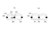
図1に示す撮像装置の構成を説明する前に、撮像素子の構造について説明する。図2(A)は本実施形態で使用する撮像素子の画素構造を模式的に示す断面図である。図2(A)には撮像画素(撮像用画素)と焦点検出画素(焦点検出用画素)を1つずつ示す。各画素はマイクロレンズ201をそれぞれ備え、配線層202が設けられている。撮像画素の光電変換部203は、マイクロレンズ201を通して受光した光を光電変換し、電気信号を出力する。焦点検出画素の光電変換部204に対しては、配線を利用して部分的な遮光を行う遮光部205が形成されている。光電変換部204は、マイクロレンズ201を通り、遮光部205により一部が遮られた光を受光して光電変換し、電気信号を出力する。撮像面位相差検出では、このような構造をもつ複数の焦点検出画素を配置することによって瞳分割された像の信号が得られる。
Embodiments of the present invention will be described below in detail with reference to the accompanying drawings.
[First Embodiment]
Before describing the configuration of the imaging apparatus illustrated in FIG. 1, the structure of the imaging element will be described. FIG. 2A is a cross-sectional view schematically showing a pixel structure of an image sensor used in the present embodiment. FIG. 2A shows one imaging pixel (imaging pixel) and one focus detection pixel (focus detection pixel). Each pixel includes a
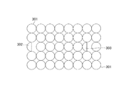
図3は撮像素子の一部である5行8列の画素配列を例示したレイアウト図である。
円形枠で示す撮像画素301は2次元アレイ状に配列されており、半円枠で示す焦点検出画素302,303が分散して配置されている。撮像画素301はその受光面全体に亘って光電変換を行う。焦点検出画素302,303は、図2(A)に示す遮光部205を有するので、受光面の一部で受光した光に対して光電変換を行う。以下、図3に例示する配列にしたがい、図4を参照して検出原理について説明する。
FIG. 3 is a layout diagram illustrating a pixel array of 5 rows and 8 columns, which is a part of the image sensor.
The
図4は、画素配列と演算内容を説明する模式図である。図3の第3行に示す6個の撮像画素301と、焦点検出画素302及び303にそれぞれ入射する光線を示す。説明の便宜のため、各画素にはP0からP7と、Q0からQ6で示す識別記号を付しており、各画素値を同様にP0からP7、またはQ0からQ6で表記する。例えば、P0,Q0は焦点検出画素302の画素値を表し、P6,Q6は焦点検出画素303の画素値を表す。P1からP5、Q1からQ5は、それぞれに対応する撮像画素301の画素値を表す。
FIG. 4 is a schematic diagram for explaining the pixel array and the calculation contents. The light beams incident on the six
図4の上段には第1露光における撮像面上での画素配列及び画素配列方向の各画素値を示している。第1露光によって得られる第1の画素信号に関し、それぞれの画素値P0からP7で示す。また、下段には第2露光における撮像面上での画素配列を示しており、第2露光により得られる第2の画素信号に関し、それぞれの画素値Q0からQ6で示す。 The upper part of FIG. 4 shows the pixel array on the imaging surface and the pixel values in the pixel array direction in the first exposure. The first pixel signal obtained by the first exposure is indicated by respective pixel values P0 to P7. The lower part shows a pixel array on the imaging surface in the second exposure, and the second pixel signal obtained by the second exposure is indicated by respective pixel values Q0 to Q6.
第2露光における撮像面は、第1露光における撮像面に対して、光軸方向にて焦点面距離Aだけ離間している。焦点調節レンズ(フォーカスレンズ)の駆動制御により、当該レンズをずらすことで瞳分割された像は、瞳分割方向に移動する。瞳分割された像の移動量と、フォーカスレンズの移動量との比をK値と記すことにすると、K値は瞳面までの距離と瞳の形状で決まる。したがって、レンズの設計情報と現在の絞り値やフォーカスレンズの位置情報等から計算によりK値を求める事ができる。 The imaging surface in the second exposure is separated from the imaging surface in the first exposure by a focal plane distance A in the optical axis direction. By driving the focus adjustment lens (focus lens), the image divided by moving the lens moves in the pupil division direction. When the ratio of the movement amount of the pupil-divided image and the movement amount of the focus lens is denoted as a K value, the K value is determined by the distance to the pupil plane and the shape of the pupil. Therefore, the K value can be obtained by calculation from the lens design information, the current aperture value, the position information of the focus lens, and the like.
第1露光では、焦点検出画素302への入射光のうち、遮光部によって遮光された事により光電変換されないエリアにB0を付記して区別するとともに、その出力値をB0と記す。また、焦点検出画素302への入射光のうちで光電変換されるエリアにA0を付記して区別するとともに、その出力値をA0と記す。つまり、遮光されるエリアでの出力値B0と、遮光されないエリアでの出力値A0との和が画素値P0である。また、自然数変数の添え字iを導入し、画素値Pi(i=1〜5,7)において2つのエリアにそれぞれAiとBiを付記して区別するとともに、各エリアの出力値をAi、Biと記す。例えば、画素値P1はA1とB1との和に等しい。図4にて画素配列方向の右端に位置する撮像画素P7については、その出力値A7のみを示す。
In the first exposure, among the incident light to the
一方、焦点検出画素303(P6参照)への入射光のうち、遮光部により遮光されずに光電変換が行われるエリアにA6を付して区別するとともに、その出力値をA6と記す。エリアA6への入射光は、P6への入射光の半分として受光されるため、画素の光軸中心に対して、偏心した角度から入射している光に相当する。画素P6にてエリアA6で光電変換される光束が、ちょうど画素1つ分だけ、画素配列方向(図4の左右方向)にずれる場合を想定し、そのときの焦点面の距離を焦点面距離Aとする。焦点面距離Aは、光軸方向に直交する方向における画素ピッチ(距離)にK値を乗算することにより算出される。本実施形態では、レンズの設計情報と制御情報に基づいて焦点面距離Aを計算する処理が実行され、フォーカスレンズを焦点面距離Aだけずらす駆動制御が行われた後、第2露光が実行される。 On the other hand, among the incident light to the focus detection pixel 303 (see P6), an area where photoelectric conversion is performed without being shielded by the light shielding portion is distinguished by attaching A6, and the output value is denoted as A6. Since the incident light to the area A6 is received as half of the incident light to P6, it corresponds to light incident from an eccentric angle with respect to the optical axis center of the pixel. Assuming that the luminous flux photoelectrically converted in the area A6 in the pixel P6 is shifted by exactly one pixel in the pixel arrangement direction (left-right direction in FIG. 4), the focal plane distance at that time is defined as the focal plane distance A. And The focal plane distance A is calculated by multiplying the pixel pitch (distance) in the direction orthogonal to the optical axis direction by the K value. In the present embodiment, a process of calculating the focal plane distance A is executed based on the lens design information and control information, and after the drive control for shifting the focus lens by the focal plane distance A is performed, the second exposure is executed. The
第2露光によって得られる信号の画素値Q0からQ6について説明すると、画素値Q0は、画素P1で光電変換される出力値A1に相当する。その理由は、出力値A1に相当する受光量は、Q0にて遮られないからである。また、画素値Q1は、P2での出力値A2と、P0での出力値B0との和に相当する。画素値Q2は、P3の出力値A3と、P1での出力値B1との和に相当する。以下、同様にして画素値Q3からQ6が求まる。 The pixel values Q0 to Q6 of the signal obtained by the second exposure will be described. The pixel value Q0 corresponds to the output value A1 that is photoelectrically converted by the pixel P1. The reason is that the received light amount corresponding to the output value A1 is not blocked by Q0. The pixel value Q1 corresponds to the sum of the output value A2 at P2 and the output value B0 at P0. The pixel value Q2 corresponds to the sum of the output value A3 of P3 and the output value B1 of P1. Thereafter, pixel values Q3 to Q6 are obtained in the same manner.
焦点検出画素302と303との間に位置する5個の撮像画素は、本来的には焦点検出画素ではない。しかし、画素値Pi(i=1〜5)は2分割されたエリアAiとBiの各出力値の和であるから、AiとBiの値をそれぞれに算出できるのであれば焦点検出画素として利用できる。つまり、エリアAiでの各出力値からA像信号を得るとともに、エリアBiでの各出力値からB像信号を得ることにより、両者の相関演算結果から像ずれ量を算出することができる。その意味でA1〜A5とB1〜B5のそれぞれを組として有する撮像画素を、「仮想焦点検出画素」と呼ぶことにする。以下、エリアAi及びBiの各出力値を算出する演算処理について説明する。
The five image pickup pixels located between the
第1露光における各画素値P0〜P6と、A0〜A6及びB1〜B5との関係は下式で表すことができる。

第2露光における各画素値Q0〜Q6と、A1〜A7及びB0〜B4との関係は下式で表すことができる。
第1露光にてA0(=P0)とA6(=P6)が既知であり、第2露光にてA1(=Q0)とA7(=Q6)が既知である。よって、これらの値から残りの仮想焦点検出画素の画素値を求めることができる。具体的には、前記の式1と式2から逆算することで、下式から仮想焦点検出画素の画素値が算出される。
このようにして得られた仮想焦点検出画素の画素値を使用することで、図5に示すように焦点検出画素302と303とともに、焦点検出素子を稠密に配列させた画素構造と実質的に等価な構造を実現できる。つまり、図5の第3行目において2分割の画素501で示すように、高密度に焦点検出画素が配置されている場合と同等の焦点検出性能が得られる事になる。各画素501の画素値を用いて、第1焦点検出信号と第2焦点検出信号を取得できるとともに、両信号を加算した信号は撮像信号として使用できる。なお、前記の式では理解のし易さを考慮し、画素値P0からP6に関して記述した。これと同様の配列をさらに連続させた画素構造の場合には、配列する画素数に応じて拡張した式を適用することにより、さらに長い配列を有する仮想焦点検出画素の画素値を算出することができる。
By using the pixel value of the virtual focus detection pixel obtained in this way, it is substantially equivalent to a pixel structure in which focus detection elements are densely arranged together with
次に、図1を参照して本実施形態に係る撮像装置の構成例を説明する。図1は撮像装置の構成において本発明に関連する部分を抽出した構成部のブロック図である。
撮像光学系を構成するレンズ部101は、絞りやフォーカスレンズ等の光学素子を備える。レンズ部101がズーム機構を有する場合にはズームレンズとその位置検出部が設けられる。撮像素子102(図2,図3参照)はレンズ部101を通して結像する光を光電変換し、撮像画素と焦点検出画素の各画素信号を出力する。欠落撮像画素補間部(以下、画素補間部という)103は、撮像素子102から焦点検出画素の信号を取得するとともに、当該焦点検出画素の周囲に位置する撮像画素の信号を取得して補間する。画素補間部103により焦点検出画素の位置での信号が補間処理により生成されるので、通常の撮像素子の場合と同様に、撮像面の全面に亘って撮像画素信号が得られる。撮像画素信号と、焦点検出画素の位置で補間処理により算出された信号は、信号処理部104に出力される。信号処理部104は所定のフォーマットに従う画像データの記録処理や画像表示処理に適した信号処理等を実行する。信号処理部104以降の回路部が行う処理については、本発明にて本質的ではないため、説明を省略する。
Next, a configuration example of the imaging apparatus according to the present embodiment will be described with reference to FIG. FIG. 1 is a block diagram of a configuration unit in which portions related to the present invention are extracted from the configuration of the imaging apparatus.
The
仮想焦点検出画素演算制御部(以下、演算制御部という)105は、撮像素子102から出力される信号を取得し、前記した仮想焦点検出画素の演算制御を行う。演算制御部105は、第1露光によって取得した信号を保存する第1画像メモリ107と、第2露光によって取得した信号を保存する第2画像メモリ106に接続されている。第1露光によって取得した信号とは、前記の例では画素値P0からP7の信号であり、第2露光によって取得した信号とは、前記の例では画素値Q0からQ6の信号である。演算制御部105は、前記の演算により仮想焦点検出画素の画素値を算出し、焦点検出画素302及び303の各画素値とともに焦点検出部108へ出力する。焦点検出部108は、焦点検出画素及び仮想焦点検出画素の各画素値に基づいて既知の相関演算を行い、撮像面位相差検出によって像ずれ量を算出してデフォーカス量に換算する。
A virtual focus detection pixel calculation control unit (hereinafter referred to as a calculation control unit) 105 acquires a signal output from the
レンズ制御部109は、レンズ部101の絞りやフォーカスレンズ等の光学素子を制御する。演算制御部105は第2露光を制御する場合と、焦点検出部108による焦点検出結果に基づいて焦点調節動作の制御を行う場合に、レンズ制御部109に対して制御信号を送信する。焦点検出部108は、焦点検出画素及び仮想焦点検出画素の各画素値に基づいて一対の像(A像とB像)データを生成し、その位相差を用いてデフォーカス量の検出を行う。レンズ制御部109は、焦点検出部108により検出されたデフォーカス量に基づいてフォーカスレンズを駆動して焦点調節動作を制御する。なお、出力801及び一時保存メモリ802については後述の実施形態で説明する。
The
図6は演算制御部105が行う処理例を示すフローチャートである。以下の処理は撮像装置全体の制御を行うシステム制御部のCPU(中央演算処理装置)が実行するプログラムにしたがって行われる。
FIG. 6 is a flowchart illustrating an example of processing performed by the
S601では、システム制御部による同期信号で処理が開始し、S602に進む。S602で第1露光が行われる。第1露光における焦点位置は、できるだけ合焦近傍である事が望ましいため、演算制御部105が動作を開始する前に、焦点検出部108は大まかな焦点検出を行う。第1露光で得られた像のデータは第1画像メモリ107へ転送されて記憶される。なお、第1画像メモリ107には、画面全体に亘るデータを保存する必要はなく、焦点検出画素と、焦点検出画素近傍における、前記演算に必要な撮像画素の各画素値を示すデータが記憶される。このことは後述する第2露光において第2画像メモリ106に記憶するデータについても同じである。
In S601, the process starts with a synchronization signal from the system control unit, and the process proceeds to S602. In S602, the first exposure is performed. Since it is desirable that the focal position in the first exposure be as close as possible to the in-focus state, the
S603で演算制御部105は第2露光での焦点位置を決定するために、焦点面距離Aを算出する。焦点面距離Aは、焦点位置、絞り値、及びズーム機構のあるレンズ部の場合にはさらにズームレンズ位置で決まる瞳分割の基線長から計算される。基線長から焦点面距離と像の横ずれの倍率を示す値Kを求めることができる。そして、1ピクセル分の像ずれ量に相当する焦点面距離Aが算出される。S604で演算制御部105は、焦点面距離Aに相当する距離だけフォーカスレンズを移動させるために、レンズ制御部109へ制御信号を送信し、レンズ制御の完了を待つ。次のS605で第2露光が行われる。第1露光の時点から第2露光の時点までの時間は、できるだけ短い事が望ましい。第2露光で得られた像のデータは第2画像メモリ106へ転送されて記憶される。
In step S <b> 603, the
S606で演算制御部105は、第1露光と第2露光における各画像データに基づき、前記の式3を適用して仮想焦点検出画素の画素値を算出する。算出された画素値のデータは、S607で焦点検出部108に転送されて、焦点検出処理が実行される。つまり、焦点検出部108は、仮想焦点検出画素の画素値のデータを受信したことを受けて焦点検出処理を開始する。レンズ制御部109は位相差検出情報に基づく既知の焦点調節制御を実行し、フォーカスレンズを合焦位置へと移動させる。
In S <b> 606, the
本実施形態では、このような手順に従って第1露光と第2露光とでそれぞれ取得される画素値を用いて、前記の演算により仮想焦点検出画素の画素値を算出することができる。すなわち、第2露光にて撮像画素及び焦点検出画素は、第1露光に対して画素ピッチ分だけずれて入射される光をそれぞれ受光して画素値を出力する。第2露光時の画素信号と第1露光時の画素信号の差分から、仮想焦点検出画素(画素配列方向にて焦点検出画素の間に位置する撮像画素)にて分割された領域での画素信号を算出することができる。よって、撮像面上で撮像画素に比べて分布密度の低い焦点検出画素の信号だけでなく、仮想焦点検出画素を含めた分布密度の高い焦点検出画素の信号が得られるので、画質低下を抑えつつ焦点検出の精度を向上させることができる。 In the present embodiment, the pixel value of the virtual focus detection pixel can be calculated by the above-described calculation using the pixel values acquired in the first exposure and the second exposure according to such a procedure. That is, in the second exposure, the imaging pixel and the focus detection pixel receive light incident with a shift of the pixel pitch with respect to the first exposure, and output a pixel value. Pixel signal in an area divided by virtual focus detection pixels (imaging pixels located between the focus detection pixels in the pixel arrangement direction) from the difference between the pixel signal at the second exposure and the pixel signal at the first exposure Can be calculated. Therefore, not only a focus detection pixel signal having a lower distribution density than the image pickup pixel on the image pickup surface but also a focus detection pixel signal having a high distribution density including the virtual focus detection pixel can be obtained, while suppressing deterioration in image quality. The accuracy of focus detection can be improved.
[第2実施形態]
次に、本発明の第2実施形態を説明する。なお、本実施形態にて第1実施形態の場合と同様の構成要素については既に使用した符号を用いることによって、それらの詳細な説明を省略し、主に相違点を説明する。このような説明の省略については後述の実施形態でも同じである。
[Second Embodiment]
Next, a second embodiment of the present invention will be described. In the present embodiment, the same constituent elements as those in the first embodiment are denoted by the same reference numerals as those used in the first embodiment, and detailed descriptions thereof are omitted, and differences are mainly described. Omitting such description is the same in the embodiments described later.
図2(B)は本実施形態に係る撮像素子の断面構造を例示する。焦点検出画素は遮光部を有しておらず、通常の画素の光電変換部203に対して、半分の大きさの光電変換部701、702を有する。光電変換部701、702は共に、同一のマイクロレンズ201を共有している。この構造により、第1実施形態のように遮光部を有する場合と同様に瞳分割が可能である。図4と同じ配列で図2(B)の焦点検出画素を配置した場合に、画素値が既知である画素はA0、B0、A1、B1、A6、B6、A7、B7となる。よって本実施形態では、第1実施形態の場合に比べて、画素情報が増えた分だけ、検算による信頼性および精度が向上する。
FIG. 2B illustrates a cross-sectional structure of the image sensor according to this embodiment. The focus detection pixel does not have a light shielding portion, and has
[第3実施形態]
次に、本発明の第3実施形態を説明する。図1において、本実施形態と第1実施形態との相違点は以下の通りである。
・演算制御部105は、出力801として仮想焦点検出画素の画素情報を、画素補間部103に転送すること。
・一時保存メモリ802が画素補間部103に接続されており、本露光時の画像データを一時的に保存すること。
本露光とは、撮像された画像データを記録媒体等に記録するために行われる露光であり、焦点検出のための第1露光や第2露光とは区別される。例えば、第1露光や第2露光とは別に露光を行う場合には当該露光が本露光となる。ただし、露光回数を削減するために、第1露光もしくは第2露光のどちらかを本露光に兼用してもよく、また第1露光及び第2露光の両方を本露光と兼用してもよい。その場合には画素補間部103が、第1露光もしくは第2露光、または第1露光及び第2露光で取得された画素値を補正して記録する。なお、撮像素子の構造については第1実施形態の場合と同様である(図2及び図4参照)。
[Third Embodiment]
Next, a third embodiment of the present invention will be described. In FIG. 1, the difference between the present embodiment and the first embodiment is as follows.
The
A
The main exposure is exposure performed to record captured image data on a recording medium or the like, and is distinguished from first exposure and second exposure for focus detection. For example, when exposure is performed separately from the first exposure and the second exposure, the exposure is the main exposure. However, in order to reduce the number of exposures, either the first exposure or the second exposure may be used for the main exposure, and both the first exposure and the second exposure may be used for the main exposure. In that case, the
本実施形態では、本露光とその後に露光(第3露光)を行う場合を説明する。本露光における画像データを使った仮想焦点検出画素の画素値のデータが作成される。作成された仮想焦点検出画素の画素値のデータに基づいて、P0,P6の画素欠落部分の画素値B0,B6を、それぞれ画素値P0,P6に加算して画素値を補正する処理が行われる。
図7は、本実施形態の本露光による撮影に同期した演算制御部105の処理を説明するフローチャートである。不図示のシステム制御部により、本露光による撮影制御への移行の指示があると、S901の処理が開始する。
In the present embodiment, a case where main exposure and subsequent exposure (third exposure) are performed will be described. Pixel value data of the virtual focus detection pixel using the image data in the main exposure is created. Based on the created pixel value data of the virtual focus detection pixels, the pixel values B0 and B6 of the pixel missing portions of P0 and P6 are added to the pixel values P0 and P6, respectively, to correct the pixel values. .
FIG. 7 is a flowchart for explaining processing of the
S902で本露光が行われ、撮像素子102から読み出された画素信号は画素補間部103と演算制御部105に入力される。演算制御部105は、本露光による画素信号を第1画像メモリ107に保存する。また画素補間部103は本露光により得られた画像データを一時保存メモリ802に保存する。
In step S <b> 902, the main exposure is performed, and the pixel signal read from the
S903では第1実施形態の場合と同様に焦点面距離Aが算出される。S904ではレンズ制御部109により、焦点面距離Aにしたがってフォーカスレンズを移動させる制御が実行される。S905で演算制御部105は第3露光を行い、焦点検出画素近傍の画素データを、第2画像メモリ106に記憶する。S906で演算制御部105は、本露光による画像、第3露光による画像の各画素値に基づいて第1実施形態にて記載した計算式を用いて仮想焦点検出画素の画素値を算出する。S907で演算制御部105は、仮想焦点検出画素の画素値を画素補間部103に出力する(図1:出力801)。画素補間部103は、一時保存メモリ802に保存されている本露光による画像データを取得する。画素補間部103は、焦点検出画素の位置において、遮光部がないとした場合に本来入射されるべき光の受光量に相当する画素値を加算することにより、撮像画素値として使用できるように補正する。具体的には、P0およびP6の欠落部分である画素値B0,B6をそれぞれ、画素値P0,P6に加算することで補正が行われる。なお、画素値B6については、図4のP0からP6と同様の画素配列が連続して繰り返される構造において、画素P7からP12の画素値を用いることでB0の場合と同様に計算される。
In S903, the focal plane distance A is calculated as in the case of the first embodiment. In step S904, the
本実施形態では、本露光後において、算出した仮想焦点検出画素の画素値を用いて、焦点検出画素の位置での画素補正を行うことができるので、撮影画像や記録画像の画質向上に寄与する。なお、前記の実施形態では瞳分割を2分割として説明した。これに限らず、1つのマイクロレンズに対して分割された複数の光電変換部を持つ構造が可能であり、4分割や9分割といった、2分割よりも多い瞳分割を行ってもよい。 In the present embodiment, after the main exposure, pixel correction at the position of the focus detection pixel can be performed using the calculated pixel value of the virtual focus detection pixel, which contributes to improving the image quality of the captured image and the recorded image. . In the above embodiment, the pupil division is described as being divided into two. However, the present invention is not limited to this, and a structure having a plurality of photoelectric conversion units divided for one microlens is possible, and more pupil divisions than two divisions such as four divisions or nine divisions may be performed.
102…撮像素子
103…欠落撮像画素補間部
105…仮想焦点検出画素演算制御部
106…第2画像メモリ
107…第1画像メモリ
108…焦点検出部
203…撮像画素の光電変換部
204,701,702…焦点検出画素の光電変換部
DESCRIPTION OF
Claims (11)
前記焦点調節レンズの駆動手段と、
前記撮像画素の画素値及び前記焦点検出画素の画素値から焦点検出信号を演算する演算手段を備え、
前記演算手段は、前記焦点調節レンズを通した第1露光によって前記焦点検出画素及び撮像画素からそれぞれ出力される第1の画素信号と、前記駆動手段が前記焦点調節レンズを前記第1露光での位置から光軸方向に移動させた第2露光によって前記焦点検出画素及び撮像画素からそれぞれ出力される第2の画素信号を取得し、前記焦点検出画素の間に配置された前記撮像画素の光電変換部が複数に分割された領域から構成されるとした場合にそれぞれの領域で得られる画素信号を算出することにより、当該撮像画素の画素値及び前記焦点検出画素の画素値から焦点検出信号を演算することを特徴とする撮像装置。 An imaging apparatus comprising: a focus adjustment lens that constitutes an imaging optical system; a focus detection pixel that receives light that has passed through each microlens; and an imaging element that includes the imaging pixel.
Driving means for the focusing lens;
Computation means for computing a focus detection signal from the pixel value of the imaging pixel and the pixel value of the focus detection pixel,
The calculation means includes a first pixel signal output from the focus detection pixel and the imaging pixel by the first exposure through the focus adjustment lens, and the drive means passes the focus adjustment lens in the first exposure. A second pixel signal output from each of the focus detection pixel and the imaging pixel is obtained by a second exposure moved from the position in the optical axis direction, and photoelectric conversion of the imaging pixel disposed between the focus detection pixels is performed. When a part is composed of a plurality of divided areas, the focus detection signal is calculated from the pixel value of the imaging pixel and the pixel value of the focus detection pixel by calculating the pixel signal obtained in each area. An imaging apparatus characterized by:
前記補正手段は、前記演算手段から前記焦点検出信号を取得し、前記第1露光もしくは第2露光、または前記第1露光及び第2露光で取得した画素値を補正して記録することを特徴とする請求項3に記載の撮像装置。 The calculation means acquires the image data captured from the first pixel signal in the first exposure, and then acquires the second pixel signal in the second exposure to calculate the focus detection signal. And
The correction means acquires the focus detection signal from the calculation means, corrects and records the pixel values acquired in the first exposure or the second exposure, or the first exposure and the second exposure. The imaging device according to claim 3.
前記演算手段は、前記第2の画素信号と前記第1の画素信号の差分から、前記撮像画素にて複数に分割された領域での画素信号を算出することを特徴とする請求項1から9のいずれか1項に記載の撮像装置。 In the second exposure, the imaging pixel and the focus detection pixel respectively receive light that is shifted by a pixel pitch in the pixel arrangement direction with respect to the first exposure, and output a pixel value.
The calculation means calculates a pixel signal in a region divided into a plurality by the imaging pixel from a difference between the second pixel signal and the first pixel signal. The imaging device according to any one of the above.
前記焦点調節レンズを通した第1露光によって前記焦点検出画素及び撮像画素からそれぞれ出力される第1の画素信号と、前記駆動手段が前記焦点調節レンズを前記第1露光での位置から光軸方向に移動させた第2露光によって前記焦点検出画素及び撮像画素からそれぞれ出力される第2の画素信号を、演算手段が取得するステップと、
前記焦点検出画素の間に配置された前記撮像画素の光電変換部が複数に分割された領域から構成されるとした場合にそれぞれの領域で得られる画素信号を前記演算手段が算出することにより、当該撮像画素の画素値及び前記焦点検出画素の画素値から焦点検出信号を演算するステップを有することを特徴とする制御方法。 A control method executed in an imaging apparatus including a focus adjustment lens and its driving means constituting an imaging optical system, and an imaging element having a focus detection pixel and an imaging pixel that receive light that has passed through a microlens, respectively. ,
A first pixel signal output from each of the focus detection pixel and the imaging pixel by the first exposure through the focus adjustment lens, and the driving means moves the focus adjustment lens from the position at the first exposure to the optical axis direction. A calculating means for obtaining a second pixel signal respectively output from the focus detection pixel and the imaging pixel by the second exposure moved to
By calculating the pixel signal obtained in each region when the photoelectric conversion unit of the imaging pixel arranged between the focus detection pixels is composed of a plurality of divided regions, A control method comprising a step of calculating a focus detection signal from a pixel value of the imaging pixel and a pixel value of the focus detection pixel.
Priority Applications (1)
| Application Number | Priority Date | Filing Date | Title |
|---|---|---|---|
| JP2014153464A JP2016031446A (en) | 2014-07-29 | 2014-07-29 | Imaging device and method of controlling the same |
Applications Claiming Priority (1)
| Application Number | Priority Date | Filing Date | Title |
|---|---|---|---|
| JP2014153464A JP2016031446A (en) | 2014-07-29 | 2014-07-29 | Imaging device and method of controlling the same |
Publications (1)
| Publication Number | Publication Date |
|---|---|
| JP2016031446A true JP2016031446A (en) | 2016-03-07 |
Family
ID=55441855
Family Applications (1)
| Application Number | Title | Priority Date | Filing Date |
|---|---|---|---|
| JP2014153464A Pending JP2016031446A (en) | 2014-07-29 | 2014-07-29 | Imaging device and method of controlling the same |
Country Status (1)
| Country | Link |
|---|---|
| JP (1) | JP2016031446A (en) |
Cited By (3)
| Publication number | Priority date | Publication date | Assignee | Title |
|---|---|---|---|---|
| CN107452346A (en) * | 2016-05-31 | 2017-12-08 | 乐金显示有限公司 | Display system and its driving method for virtual reality |
| CN110401968A (en) * | 2019-05-09 | 2019-11-01 | 岳文伟 | Wireless communication system based on density analysis |
| CN110677814A (en) * | 2019-05-09 | 2020-01-10 | 岳文伟 | Wireless communication method based on density analysis |
-
2014
- 2014-07-29 JP JP2014153464A patent/JP2016031446A/en active Pending
Cited By (4)
| Publication number | Priority date | Publication date | Assignee | Title |
|---|---|---|---|---|
| CN107452346A (en) * | 2016-05-31 | 2017-12-08 | 乐金显示有限公司 | Display system and its driving method for virtual reality |
| US10558046B2 (en) | 2016-05-31 | 2020-02-11 | Lg Display Co., Ltd. | Display system for virtual reality and method of driving the same |
| CN110401968A (en) * | 2019-05-09 | 2019-11-01 | 岳文伟 | Wireless communication system based on density analysis |
| CN110677814A (en) * | 2019-05-09 | 2020-01-10 | 岳文伟 | Wireless communication method based on density analysis |
Similar Documents
| Publication | Publication Date | Title |
|---|---|---|
| JP5954964B2 (en) | Imaging apparatus and control method thereof | |
| JP5219865B2 (en) | Imaging apparatus and focus control method | |
| JP2013072906A (en) | Imaging apparatus | |
| JP6053347B2 (en) | Imaging apparatus, control method therefor, and program | |
| JP5914192B2 (en) | Imaging apparatus and control method thereof | |
| JP5633181B2 (en) | Depth map output device | |
| JP2014039311A5 (en) | Imaging device, shading correction method for imaging device, and program for imaging device | |
| JP5448621B2 (en) | IMAGING DEVICE AND IMAGING DEVICE CONTROL METHOD | |
| JP2017107204A (en) | Information processing apparatus and information processing method | |
| KR20150047112A (en) | Imaging apparatus and its control method, and storage medium | |
| JP5784395B2 (en) | Imaging device | |
| US10362214B2 (en) | Control apparatus, image capturing apparatus, control method, and non-transitory computer-readable storage medium | |
| JP2016031446A (en) | Imaging device and method of controlling the same | |
| JP2021027523A5 (en) | ||
| JP6198395B2 (en) | Imaging apparatus and control method thereof | |
| JP2017207695A (en) | Optical device | |
| JP6741549B2 (en) | Imaging device and control method thereof | |
| JP5893412B2 (en) | Imaging apparatus and control method thereof | |
| JP2016057402A (en) | Imaging device and method for controlling the same | |
| JP2014064214A5 (en) | ||
| JP6566800B2 (en) | Imaging apparatus and imaging method | |
| JP2016100868A (en) | Image processing apparatus, image processing method, and program, and imaging apparatus | |
| JP7187185B2 (en) | Imaging device and its control method | |
| JP5882785B2 (en) | Imaging device | |
| JP6532411B2 (en) | IMAGE PROCESSING DEVICE, IMAGING DEVICE, AND IMAGE PROCESSING PROGRAM |