JP2016018760A - connector - Google Patents
connector Download PDFInfo
- Publication number
- JP2016018760A JP2016018760A JP2014143046A JP2014143046A JP2016018760A JP 2016018760 A JP2016018760 A JP 2016018760A JP 2014143046 A JP2014143046 A JP 2014143046A JP 2014143046 A JP2014143046 A JP 2014143046A JP 2016018760 A JP2016018760 A JP 2016018760A
- Authority
- JP
- Japan
- Prior art keywords
- connector
- male
- cable
- probe
- hole
- Prior art date
- Legal status (The legal status is an assumption and is not a legal conclusion. Google has not performed a legal analysis and makes no representation as to the accuracy of the status listed.)
- Granted
Links
- 239000000523 sample Substances 0.000 claims abstract description 110
- 230000008602 contraction Effects 0.000 claims description 14
- 239000011248 coating agent Substances 0.000 claims description 2
- 238000000576 coating method Methods 0.000 claims description 2
- 238000007689 inspection Methods 0.000 abstract description 41
- 230000008878 coupling Effects 0.000 abstract 1
- 238000010168 coupling process Methods 0.000 abstract 1
- 238000005859 coupling reaction Methods 0.000 abstract 1
- XLYOFNOQVPJJNP-UHFFFAOYSA-N water Substances O XLYOFNOQVPJJNP-UHFFFAOYSA-N 0.000 description 15
- 239000000463 material Substances 0.000 description 6
- 238000010586 diagram Methods 0.000 description 3
- 239000002184 metal Substances 0.000 description 3
- OKTJSMMVPCPJKN-UHFFFAOYSA-N Carbon Chemical compound [C] OKTJSMMVPCPJKN-UHFFFAOYSA-N 0.000 description 2
- 229910052799 carbon Inorganic materials 0.000 description 2
- 239000005871 repellent Substances 0.000 description 2
- 239000011347 resin Substances 0.000 description 2
- 229920005989 resin Polymers 0.000 description 2
- 125000002066 L-histidyl group Chemical group [H]N1C([H])=NC(C([H])([H])[C@](C(=O)[*])([H])N([H])[H])=C1[H] 0.000 description 1
- 230000015572 biosynthetic process Effects 0.000 description 1
- 230000006866 deterioration Effects 0.000 description 1
- 239000000284 extract Substances 0.000 description 1
- 230000002209 hydrophobic effect Effects 0.000 description 1
- 238000012986 modification Methods 0.000 description 1
- 230000004048 modification Effects 0.000 description 1
- 230000000149 penetrating effect Effects 0.000 description 1
- 230000035515 penetration Effects 0.000 description 1
- 230000000737 periodic effect Effects 0.000 description 1
- 239000004033 plastic Substances 0.000 description 1
Images


Landscapes
- Connector Housings Or Holding Contact Members (AREA)
Abstract
Description
本発明は、自動車といった車両などで用いられるコネクタに関する。 The present invention relates to a connector used in a vehicle such as an automobile.
自動車などの車両では、たとえばヘッドランプモジュールとバッテリとを、複数の被覆ケーブルを束ねたハーネスで接続している。そして、ヘッドランプモジュールとハーネスとは、それらに設けられたコネクタ同士を連結することにより、電気的に接続される。 In vehicles such as automobiles, for example, a headlamp module and a battery are connected by a harness in which a plurality of covered cables are bundled. And a headlamp module and a harness are electrically connected by connecting the connectors provided in them.
ところで、このように車両などで用いられるコネクタでは、雨などの水滴がかかる可能性がある。このため、コネクタには、防水性能を持たせることが求められている。特に、たとえば車両で用いられるハーネス用のコネクタでは、複数の被覆ケーブルがコネクタの筐体の一面に並べて配列されるため、複数の被覆ケーブルの間が水で濡れる可能性がある。仮に複数の被覆ケーブルの芯線同士が電気的に接続されると、それらの被覆ケーブルで伝送しようとする信号または電力が正しく伝わらなくなる可能性が生じる。
そして、特許文献1では、露出している単独の端子金具の防水性能を得るために、該端子金具をゴム製の防水カバーで被覆することを開示する。特許文献2は、複数の被覆ケーブルをコネクタで連結する際に、コネクタおよび連結部分の全体をコネクタカバーで被覆することを開示する。
By the way, in such a connector used in a vehicle or the like, water droplets such as rain may be applied. For this reason, the connector is required to have waterproof performance. In particular, in a connector for a harness used in a vehicle, for example, a plurality of covered cables are arranged side by side on one surface of the housing of the connector, so there is a possibility that the plurality of covered cables get wet with water. If the core wires of a plurality of covered cables are electrically connected to each other, there is a possibility that a signal or power to be transmitted through these covered cables cannot be transmitted correctly.
And in
このようにコネクタでは、防水性能が求められる一方で、コネクタを用いる電気回路において不具合が発生した場合や定期点検の場合にヘッドランプモジュールやハーネスの性能を検査する必要がある。そして、この検査では、ヘッドランプモジュールとハーネスとを連結したままで検査することが望まれている。
しかしながら、特許文献1の防水カバーや特許文献2のコネクタカバーを用いた場合、これらカバーの外から被覆ケーブルの芯線へアクセスすることはできない。
特に、特許文献2では、3本の被覆ケーブルを連結可能なコネクタカバーにより、2本の被覆ケーブルを連結した例を開示している。この場合、未使用のケーブル孔が残されている。このため、このコネクタカバーの未使用のケーブル孔から検査装置のプローブを挿入することが考えられる。しかしながら、未使用のケーブル孔に検査装置のプローブを挿入した場合、検査後には、コネクタカバーにおいて該未使用のケーブル孔に開口が形成されてしまう。その結果、コネクタカバーの防水性能は検査により毀損されてしまう。
Thus, while the connector is required to have waterproof performance, it is necessary to inspect the performance of the headlamp module and the harness when a failure occurs in the electric circuit using the connector or during periodic inspection. In this inspection, it is desired to perform the inspection while the headlamp module and the harness are connected.
However, when the waterproof cover of
In particular,
このように、コネクタでは、該コネクタと他のコネクタとの連結を維持したまま、防水性能を損なうことなく、検査装置のプローブにより検査できるようにすることが求められている。 As described above, the connector is required to be inspected by the probe of the inspection apparatus while maintaining the connection between the connector and the other connector without impairing the waterproof performance.
本発明に係るコネクタは、他のコネクタと嵌め合わされる筐体と、前記筐体に並べて形成され、複数の被覆ケーブルが個別に挿入される複数のケーブル孔と、前記筐体内で前記複数の被覆ケーブルと接続され、前記筐体が前記他のコネクタと嵌め合わされた場合に前記他のコネクタと電気的に接続される複数の端子と、前記ケーブル孔を塞ぐように前記ケーブル孔内に設けられ、前記ケーブル孔に挿入される被覆ケーブルと電気的に接続される導電性の伸縮部材と、前記ケーブル孔内の前記導電性の伸縮部材において、前記ケーブル孔内で被覆ケーブルと並べて形成されるプローブ孔と、を有する。 The connector according to the present invention includes a housing fitted with another connector, a plurality of cable holes formed side by side in the housing, into which a plurality of covered cables are individually inserted, and the plurality of coverings in the housing. A plurality of terminals that are connected to a cable and electrically connected to the other connector when the housing is fitted with the other connector, and provided in the cable hole so as to close the cable hole; A conductive elastic member electrically connected to the covered cable inserted into the cable hole, and a probe hole formed side by side with the covered cable in the cable hole in the conductive elastic member in the cable hole And having.
好適には、前記ケーブル孔内において前記導電性の伸縮部材の外側に設けられ、前記導電性の伸縮部材を被覆する非導電性のオス伸縮部材と、前記非導電性のオス伸縮部材において前記プローブ孔に対応する位置に形成される切り込みと、を有する、とよい。 Preferably, a non-conductive male elastic member provided outside the conductive elastic member in the cable hole and covering the conductive elastic member; and the probe in the non-conductive male elastic member It is good to have the notch formed in the position corresponding to a hole.
好適には、前記導電性の伸縮部材の内側には、少なくとも前記プローブ孔の内側となる部分に、硬質部材が設けられる、とよい。 Preferably, a hard member is provided on the inner side of the conductive elastic member at least in a portion that is on the inner side of the probe hole.
好適には、前記プローブ孔の内面は、凹凸に形成される、とよい。 Preferably, the inner surface of the probe hole is formed to be uneven.
好適には、前記被覆ケーブルは、芯線を被覆部で被覆したものであり、前記導電性の伸縮部材内で前記芯線が露出する、とよい。 Suitably, the said covered cable is a thing which coat | covered the core wire with the coating | coated part, and it is good for the said core wire to expose in the said electrically conductive elastic member.
本発明のコネクタについての他のコネクタと嵌め合わされる筐体には、複数の被覆ケーブルが個別に挿入される複数のケーブル孔が並べて形成される。よって、本発明のコネクタは、たとえば車両用のハーネスの接続に利用できる。しかも、ケーブル孔内には、ケーブル孔を塞ぐように伸縮部材が設けられる。よって、ケーブル孔から筐体内へ水分が侵入し難くなる。たとえば被覆ケーブルの芯線が端子と接続される部分まで、水分が侵入し難くなる。たとえば車両用のコネクタとして利用可能な防水性能が得られる。
しかも、ケーブル孔を塞ぐ導電性の伸縮部材はケーブル孔毎に設けられている。このため、仮にたとえば隣接する複数の被覆ケーブルの間の筐体の表面が水に濡れたとしても、これら複数の導電性の伸縮部材の間が電気的に接続され難い。
また、ケーブル孔を塞ぐ導電性の伸縮部材には、被覆ケーブルと並べてプローブ孔が形成される。プローブ孔は、ケーブル孔内で被覆ケーブルと並べて形成される。よって、たとえば検査装置のプローブをプローブ孔に刺すことにより、該コネクタを他のコネクタと連結させたまま、検査することができる。また、検査装置のプローブをプローブ孔に刺した状態に保持できるので、検査中にプローブを人手で支える必要がない。検査作業が容易になる。
このように、本発明のコネクタは、他のコネクタとの連結を維持したまま、防水性能を損なうことなく、検査装置のプローブにより検査できる。
A plurality of cable holes into which a plurality of covered cables are individually inserted are formed side by side in a housing fitted with another connector of the connector of the present invention. Therefore, the connector of this invention can be utilized for the connection of the harness for vehicles, for example. In addition, an elastic member is provided in the cable hole so as to close the cable hole. Therefore, it becomes difficult for moisture to enter the housing from the cable hole. For example, it becomes difficult for moisture to penetrate to the portion where the core wire of the coated cable is connected to the terminal. For example, waterproof performance that can be used as a connector for a vehicle is obtained.
Moreover, a conductive elastic member that closes the cable hole is provided for each cable hole. For this reason, even if, for example, the surface of the housing between the plurality of adjacent covered cables gets wet with water, it is difficult to electrically connect the plurality of conductive elastic members.
In addition, a probe hole is formed in the conductive elastic member that closes the cable hole side by side with the covered cable. The probe hole is formed side by side with the covered cable in the cable hole. Therefore, for example, by inserting the probe of the inspection apparatus into the probe hole, the inspection can be performed while the connector is connected to another connector. Further, since the probe of the inspection apparatus can be held in a state where it is stuck in the probe hole, it is not necessary to manually support the probe during the inspection. Inspection work becomes easy.
As described above, the connector of the present invention can be inspected by the probe of the inspection apparatus without damaging the waterproof performance while maintaining the connection with other connectors.
以下、本発明の実施形態を図面に基づいて説明する。 Hereinafter, embodiments of the present invention will be described with reference to the drawings.
図1は、自動車1の電装系の一例を示す概略説明図である。自動車1は、車両の一例である。
自動車1の電装系は、図1に例示するように、バッテリ11、ECU12(Engine Control Unit)、ヘッドランプモジュール13、ランプスイッチ14、ハーネス15、を有する。
バッテリ11、ECU12、ヘッドランプモジュール13、ランプスイッチ14といった電装部品は、自動車1の車体2に分散して配置される。
ハーネス15は、複数の被覆ケーブル16を束ねたものである。複数の被覆ケーブル16の先端には、コネクタが取り付けられる。ハーネス15は、たとえば図1に一部の電装部品を示すように、自動車1の車体2に分散して配置されるバッテリ11、ECU12、ヘッドランプモジュール13といった電装部品と連結される。
FIG. 1 is a schematic explanatory diagram illustrating an example of an electrical system of the
As illustrated in FIG. 1, the electrical system of the
Electrical components such as the
The
車体2に分散して取り付けられる電装部品は、ハーネス15と連結されることにより、必要な他の電装部品と電気的に接続される。たとえばヘッドランプモジュール13は、ハーネス15と連結されることにより、ハーネス15の被覆ケーブル16によりバッテリ11と電気的に接続され、バッテリ11の蓄電電力により点灯可能になる。また、ヘッドランプモジュール13は、ハーネス15と連結されることにより、ハーネス15の被覆ケーブル16によりECU12と電気的に接続され、ランプスイッチ14の操作に基づいてECU12から出力される制御信号により点灯および消灯が制御される。
そして、このように複数の被覆ケーブル16を束ねてハーネス15としてアセンブリ化することにより、車体2に対して電装系の取付作業が容易になる。
また、ハーネス15と電装部品との連結には、コネクタが用いられる。コネクタには、オスコネクタと、メスコネクタとがある。オスコネクタをメスコネクタに挿入することで、オスコネクタとメスコネクタとが連結される。これにより、ハーネス15は、複数の電装部品同士を電気的に接続できる。
The electric parts dispersedly attached to the
Then, by bundling the plurality of
A connector is used to connect the
図2は、本発明の実施形態に係るオスコネクタ21およびメスコネクタ41の連結状態を示す概略斜視図である。図2のオスコネクタ21およびメスコネクタ41は、図1の車両に用いることができる。
図3は、図2のオスコネクタ21の概略断面図である。
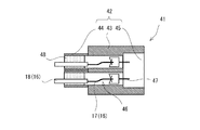
図4は、図2のメスコネクタ41の概略断面図である。
図5は、図2のオスコネクタ21とメスコネクタ41とを連結した状態での概略断面図である。
たとえば、図2のオスコネクタ21は、ハーネス15の複数の被覆ケーブル16に連結される。メスコネクタ41は、たとえばヘッドランプモジュール13の複数の被覆ケーブル16に連結される。
FIG. 2 is a schematic perspective view showing a connected state of the
FIG. 3 is a schematic cross-sectional view of the
4 is a schematic cross-sectional view of the
FIG. 5 is a schematic cross-sectional view of the
For example, the
オスコネクタ21は、オス筐体22、複数のオス端子27、複数の非導電性のオス伸縮部材28、複数の導電性の伸縮部材29、複数の硬質部材30、を有する。
メスコネクタ41は、メス筐体42、複数のメス端子47、複数のメス非導電性の伸縮部材48、を有する。
The
The
オス筐体22およびメス筐体42は、たとえば非導電性の硬質樹脂材料から形成される。
オス筐体22は、オス立方体部23、突起部24、複数のオス円筒部25、複数のオスケーブル孔26、を有する。オス立方体部23は、略立方体形状を有する。複数のオス円筒部25は、略立方体形状のオス立方体部23の一面に配列して設けられる。図2では、8個のオス円筒部25が二列で配列されている。突起部24は、略立方体形状のオス立方体部23についての、オス円筒部25が形成された面と対向する面から突出する。オスケーブル孔26は、オス円筒部25から突起部24にかけて形成される。オスケーブル孔26は、略円筒形状の内面を有する。
メス筐体42は、メス立方体部43、嵌合穴44、複数のメス円筒部45、複数のメスケーブル孔46、を有する。メス立方体部43は、オス立方体部23と略同サイズの略立方体形状を有する。複数のメス円筒部45は、略立方体形状のメス立方体部43の一面に配列して設けられる。図2では、8個のメス円筒部45が二列で配列されている。嵌合穴44は、略立方体形状のメス立方体部43についての、メス円筒部45が形成された面と対向する面に形成される。メスケーブル孔46は、メス円筒部45から嵌合穴44にかけて形成される。メスケーブル孔46は、略円筒形状の内面を有する。
そして、オス筐体22とメス筐体42とは、突起部24を嵌合穴44に挿入することにより、連結される。なお、オス筐体22およびメス筐体42には、互いを嵌合した状態に保持するための係合部を設けてよい。
The
The
The
The
オスコネクタ21のオス端子27は、オスケーブル孔26に配置される。オス端子27は、オスケーブル孔26において、突起側の端部に配置される。
メスコネクタ41のメス端子47は、メスケーブル孔46に配置される。メス端子47は、メスケーブル孔46において、嵌合穴44側の端部に配置される。
オス筐体22とメス筐体42とを連結した場合に、オス端子27は、メス端子47と接触する。これにより、オスコネクタ21とメスコネクタ41とが電気的に接続される。
The
The
When the
また、オスケーブル孔26には、オス端子27とは反対の外側から、ハーネス15の被覆ケーブル16が挿入される。被覆ケーブル16は、芯線17と、芯線17を被覆する被覆部18と、を有する。芯線17は、たとえば複数の金属線を撚り合わせたものである。被覆部18は、絶縁性の樹脂材料からなり、芯線17を覆う。オス筐体22のオスケーブル孔26内で、被覆ケーブル16の芯線17は、露出する。露出した芯線17の先端は、オス端子27と接続される。
メスケーブル孔46には、メス端子47の反対側から、ヘッドランプモジュール13の被覆ケーブル16が挿入される。オス筐体22のオスケーブル孔26内で、被覆ケーブル16の芯線17は、露出する。露出した芯線17の先端は、メス端子47と接続される。
これにより、オス筐体22とメス筐体42とを連結した場合に、ハーネス15の複数の被覆ケーブル16の芯線17と、ヘッドランプモジュール13の被覆ケーブル16の芯線17とは、電気的に接続される。これらの芯線17を通じて、たとえばバッテリ11からヘッドランプモジュール13へ給電したり、ECU12からヘッドランプモジュール13へ制御信号を伝送したりできる。
Further, the covered
The covered
Thereby, when the
ところで、このようなオスコネクタ21およびメスコネクタ41を用いて、複数の被覆ケーブル16を連結する場合、オスコネクタ21およびメスコネクタ41には、たとえば防水性能と検査性能とを両立することが求められる。
By the way, when connecting the some covered
防水性能について言えば、自動車1の電装部品は、必ずしも外界から隔離された状態で車体2に取り付けられているわけではない。たとえば車体2の前部に設けられるヘッドランプモジュール13は車体2のエンジン室に露出する。そして、ヘッドランプモジュール13のメスコネクタ41と、ハーネス15のオスコネクタ21とは、エンジン室内で連結される。そして、フードカバーを開くことにより、エンジン室は露出する。また、エンジン室の下側は、一般的に塞がれていない。よって、エンジン室内に雨などの水分が入る可能性がある。その結果、通常の使用状態では略あり得ないことではあるが、ヘッドランプモジュール13のメスコネクタ41とハーネス15のオスコネクタ21との連結部分に、水に濡れてしまう可能性が残されている。オス筐体22およびメス筐体42の内部に水が浸入してしまう可能性がある。また、オス筐体22に配列される複数のオスケーブル孔26の間が濡れて、隣接する複数の被覆ケーブル16の間が水で濡れる可能性がある。仮に隣接する複数の被覆ケーブル16の芯線17同士が電気的に接続されると、それらの被覆ケーブル16で伝送しようとする信号または電力が正しく伝わらなくなる可能性が生じる。
このため、複数のオスケーブル孔26および複数のメスケーブル孔46を、たとえば非導電性のオス伸縮部材28で塞ぐことが考えられる。これにより、オス筐体22およびメス筐体42の内部に水が浸入し難くなる。また、隣接する複数の被覆ケーブル16の芯線17同士が電気的に接続され難くなる。
Speaking of waterproof performance, the electrical components of the
For this reason, it is conceivable to close the plurality of male cable holes 26 and the plurality of female cable holes 46 with, for example, a non-conductive male expansion /
検査性能について言えば、自動車1の電装系は、たとえば車検などにおいて正常に動作しているか否かを検査する必要がある。また、ヘッドランプモジュール13が点灯しないなどの不具合が発生した場合、その不具合の原因を究明し、故障した電装部品を交換する必要がある。たとえばヘッドランプモジュール13が点灯しない原因がハーネス15の断線にあるのか、ヘッドランプモジュール13内での故障が原因であるのかを判別しなければならない。
このため、自動車1の電装系では、テスタなどの検査装置のプローブ51を、たとえば被覆ケーブル16の芯線17に当てて、その電気的特性や信号を測定する必要がある。
そして、現在では、被覆部18で覆われた被覆ケーブル16の芯線17は、被覆部18、オスコネクタ21およびメスコネクタ41により被覆されており、その防水性能を損なうことがないように検査するためには、オスコネクタ21をメスコネクタ41から外し、その状態で各々の電装系を検査している。
たとえばオスケーブル孔26にプローブ51を挿入して、被覆ケーブル16の芯線17にプローブ51を当てることも考えられるが、この場合、プローブ51をオスケーブル孔26から抜いた検査後には、オスケーブル孔26を塞いでいる非導電性のオス伸縮部材28には、プローブ51により貫通孔が形成されてしまう。貫通孔による開口から、たとえばオス筐体22内へ水分が侵入できるようになってしまう。
また、オスコネクタ21をメスコネクタ41から外して、オスコネクタ21側の系統とメスコネクタ41側の系統とを別々に検査した場合、それらが接続されている不具合が発生した状態のままで電装系を一体的に検査することができない。複合的な原因により不具合となっている場合、その不具合の原因を特定することができない可能性がある。
With regard to the inspection performance, it is necessary to inspect whether or not the electrical system of the
For this reason, in the electrical system of the
At present, the
For example, it is conceivable that the
Moreover, when the
このように、自動車1といった車両などで用いられるコネクタでは、オスコネクタ21とメスコネクタ41との連結を維持したまま、防水性能を損なうことなく、検査装置のプローブ51により検査できるようにすることが求められている。
以下、本実施形態での解決策を具体的に説明する。本実施形態では、本発明をオスコネクタ21に適用している。なお、本発明は、メスコネクタ41に適用してもよい。また、オスコネクタ21およびメスコネクタ41に対して本発明を共に適用してもよい。
As described above, in a connector used in a vehicle such as the
Hereinafter, the solution in this embodiment is demonstrated concretely. In the present embodiment, the present invention is applied to the
図3に示すように、オスコネクタ21のオスケーブル孔26内には、外側から順番に、非導電性のオス伸縮部材28、導電性の伸縮部材29、および硬質部材30、が配置される。非導電性のオス伸縮部材28、導電性の伸縮部材29、および硬質部材30は、オスケーブル孔26の内径に合わせた外径に形成される。オスケーブル孔26は、塞がれる。
導電性の伸縮部材29は、たとえばカーボンを混ぜたゴム材からなる。カーボンを混ぜることにより、伸縮部材29に導電性が得られる。
非導電性のオス伸縮部材28は、たとえば撥水性の非導電性ゴム材料からなる。非導電性のオス伸縮部材28は、略円柱形状の導電性の伸縮部材29の外面に貼着される。非導電性のオス伸縮部材28は、導電性の伸縮部材29の外側に露出して設けられる。これにより、導電性の伸縮部材29は被覆されて外に露出しなくなる。
硬質部材30は、たとえばプラスチック材料からなる。硬質部材30は、略円柱形状の導電性の伸縮部材29の内面に貼着される。
As shown in FIG. 3, a non-conductive male expansion /
The conductive
The non-conductive male
The
オスケーブル孔26に挿入される被覆ケーブル16は、非導電性のオス伸縮部材28、導電性の伸縮部材29、および硬質部材30を貫通する。被覆ケーブル16の芯線17は、導電性の伸縮部材29からオス端子27までの間で露出する。これにより、導電性の伸縮部材29は、被覆ケーブル16の芯線17と電気的に接続される。
The covered
導電性の伸縮部材29には、プローブ51を差し込むためのプローブ孔31が形成される。プローブ孔31は、被覆ケーブル16と並べて、オスケーブル孔26の軸方向に沿って形成される。プローブ孔31は、導電性の伸縮部材29の外側の面に開口し、導電性の伸縮部材29についての該外面から中央部にかけて形成される。プローブ孔31は、導電性の伸縮部材29を貫通しないように形成される。
また、プローブ孔31の内面は、外側から見て逆ひだ形状に形成される。これにより、プローブ孔31の内面は、プローブ孔31の軸方向に沿って凹凸に形成される。プローブ孔31に刺し込まれたプローブ51は、凸部に引っ掛かり、プローブ孔31から容易に抜けなくなる。作業者がプローブ51から手を離しても、検査中にプローブ51がプローブ孔31から脱落し難くなる。検査中に作業者がプローブ51を支える必要はない。
A
Further, the inner surface of the
非導電性のオス伸縮部材28には、プローブ孔31と重なる位置に切り込み32が形成される。切り込み32は、通常は閉じている。
また、硬質部材30は、略円柱形状の導電性の伸縮部材29の内側の全面に貼り付けられている。よって、少なくともプローブ孔31の内側となる部分には、硬質部材30が設けられる。
A
The
次に、検査装置のプローブ51をオスコネクタ21に挿抜する作業について説明する。
図6は、検査装置のプローブ51を挿入した状態およびその前後の状態を示す説明図である。
図6(A)に示すように、プローブ51を挿入する前では、プローブ孔31内の表面を構成する非導電性のオス伸縮部材28の切り込み32は、閉じている。
よって、この状態で、仮にたとえば非導電性のオス伸縮部材28の表面に水滴が付くことがあったとしても、その水滴が導電性の伸縮部材29のプローブ孔31へ入り込むことはない。ましてや、オス筐体22内へ水分が入り込むことはない。
また、プローブ孔31内には、撥水性の非導電性のオス伸縮部材28により塞がれている。よって、隣接する複数のプローブ孔31の間が水に濡れたとしても、その水分により、隣接する複数の導電性の伸縮部材29の間を電気的に接続してしまうことはない。高い防水性能が得られる。
Next, the operation | work which inserts / extracts the
FIG. 6 is an explanatory diagram showing a state in which the
As shown in FIG. 6A, before the
Therefore, in this state, even if, for example, water droplets may be attached to the surface of the non-conductive male expansion /
Further, the
検査をする場合、図6(B)に示すように、作業者は、プローブ51を、非導電性のオス伸縮部材28の切り込み32から差し込む。切り込み32に挿入されたプローブ51は、さらに導電性の伸縮部材29のプローブ孔31に挿入される。そして、プローブ孔31の内面が逆ひだ形状に形成されているので、差し込んだプローブ51を軽く引いたとしても、プローブ51がプローブ孔31から脱落しない。また、プローブ孔31に刺しこまれたプローブ51は、導電性の伸縮部材29と接触した状態に保持され、被覆ケーブル16の芯線17と電気的に接続される。このようにプローブ51の先端が導電性の伸縮部材29に当たる状態でプローブ51を保持できるので、検査装置は、被覆ケーブル16の芯線17の電位などを正確に計測できる。
なお、作業者が強くプローブ51を押し込んだ場合、ゴム材料を基材としている導電性の伸縮部材29が裂けて、プローブ51が導電性の伸縮部材29を突き抜けてしまう可能性がある。しかしながら、本実施形態では、導電性の伸縮部材29の内側に硬質部材30を貼着している。よって、プローブ51が強く押し込まれても、先端が硬質部材30に当たる前にプローブ51が止まり易い。プローブ51が導電性の伸縮部材29を
突き抜けないようにできる。プローブ51は、その先端が導電性の伸縮部材29と接触する状態に維持され易い。よって、検査装置は、プローブ51の先端により、被覆ケーブル16の芯線17の電位などを正確に計測できる。
When inspecting, as shown in FIG. 6B, the operator inserts the
When the operator strongly pushes the
It can be prevented from penetrating. The
検査を終えると、図6(C)に示すように、作業者は、プローブ51をプローブ孔31および切り込み32から引き抜く。プローブ51が引き抜かれることにより、切り込み32が閉じる。
よって、プローブ51を引き抜いた後でも、非導電性のオス伸縮部材28の切り込み32が閉じるので、導電性の伸縮部材29のプローブ孔31へ水滴が入り込み難くなる。また、隣接する複数のプローブ孔31の間が水に濡れたとしても、それらのプローブ孔31は疎水性の非導電性のオス伸縮部材28により塞がれているので、その水分により、隣接する複数の導電性の伸縮部材29が電気的に接続されてしまうこともない。検査後も高い防水性能を維持できる。
When the inspection is completed, the operator pulls out the
Therefore, even after the
以上のように、本実施形態では、オスコネクタ21において、被覆ケーブル16が個別に挿入されるオスケーブル孔26を導電性の伸縮部材29で塞ぎ、該導電性の伸縮部材29には、被覆ケーブル16と並べて伸縮部材を貫通しないようにプローブ孔31を形成している。
よって、本実施形態では、オスコネクタ21のオス筐体22内へ水分が侵入し難くなる。被覆ケーブル16の芯線17が露出してオス端子27と接続される部分まで、水分が侵入し難くなる。しかも、オスケーブル孔26を塞ぐ伸縮部材29が導電性を有しているが、この導電性の伸縮部材29はオスケーブル孔26毎に設けられている。よって、隣接する複数の被覆ケーブル16の間においてオス筐体22の表面が水に濡れたとしても、これら複数の被覆ケーブル16の芯線17の間が電気的に接続され難い。たとえば車両用のコネクタとして利用可能な防水性能が得られる。
また、オスケーブル孔26を塞ぐ導電性の伸縮部材29には、被覆ケーブル16と並べてプローブ孔31が形成される。よって、検査装置のプローブ51をプローブ孔31に刺して、該オスコネクタ21を他のメスコネクタ41と連結したまま、検査することができる。また、検査装置のプローブ51をプローブ孔31に刺した状態に保持できるので、検査中に人手によりプローブ51を支える必要もない。検査作業が容易になる。特に、プローブ51が導電性の伸縮部材29を貫通し難いので、プローブ51が貫通したことにより形成される貫通孔を通じてオス筐体22の内部へ水分が侵入することはない。
このように、本実施形態のオスコネクタ21では、他のメスコネクタ41との連結を維持したまま、防水性能を損なうことなく、検査装置のプローブ51により検査できる。
As described above, in the present embodiment, in the
Therefore, in this embodiment, it becomes difficult for moisture to enter the
Further, a
Thus, in the
また、本実施形態では、導電性の伸縮部材29を非導電性のオス伸縮部材28により露出しないように被覆し、該非導電性のオス伸縮部材28に切り込み32を形成している。よって、隣接する複数のオスケーブル孔26の間が水に濡れたとしても、該隣接する複数のオスケーブル孔26内の導電性の伸縮部材29同士が電気的に接続され難い。高い防水性能が得られる。しかも、非導電性のオス伸縮部材28には、プローブ孔31に対応する位置に切り込み32が形成されているので、高い防水性能を損なうことなく、オスコネクタ21とメスコネクタ41との連結を維持したまま検査することができる。
しかも、プローブ51を刺すために非導電性のオス伸縮部材28に形成される孔は、単なる切り込み32であるので、プローブ51を抜くことにより切り込み32が閉じる。検査後に切り込み32が開いたままになり難く、検査後においても高い防水性能を維持することができる。
In this embodiment, the conductive
Moreover, since the hole formed in the non-conductive male
また、本実施形態では、導電性の伸縮部材29の内側には、少なくともプローブ孔31の内側となる部分に、硬質部材30が設けられる。
よって、本実施形態では、検査装置のプローブ51が導電性の伸縮部材29を突き抜け難くなる。プローブ孔31に挿入されたプローブ51は、その先端が導電性の伸縮部材29と接触した状態になる。これにより、プローブ51の先端部分により、正確な検査が可能となる。また、プローブ51の先端が導電性の伸縮部材29を突き抜け難いので、検査後に導電性の伸縮部材29に貫通孔が形成され難い。貫通孔が形成されることによる防水性能の劣化の可能性を無くすことができる。
Further, in the present embodiment, the
Therefore, in this embodiment, it becomes difficult for the
また、本実施形態では、プローブ孔31の内面は、逆ひだ形状により、プローブ孔31の軸方向に沿って凹凸に形成される。
よって、本実施形態では、プローブ孔31に挿入したプローブ51が検査中に抜け難くなる。
Further, in the present embodiment, the inner surface of the
Therefore, in this embodiment, the
以上の実施形態は、本発明の好適な実施形態の例であるが、本発明は、これに限定されるものではなく、発明の要旨を逸脱しない範囲において、種々の変形または変更が可能である。 The above embodiment is an example of a preferred embodiment of the present invention. However, the present invention is not limited to this, and various modifications or changes can be made without departing from the scope of the invention. .
たとえば上記実施形態では、オスケーブル孔26には、非導電性のオス伸縮部材28、導電性の伸縮部材29、および硬質部材30が設けられる。
この他にもたとえば、複数のオスケーブル孔26が隣接して配列されていない場合などにおいては、オスケーブル孔26には、導電性の伸縮部材29、および硬質部材30を設けるだけでもよい。
さらに他にもたとえば、プローブ51が導電性の伸縮部材29を貫通しても防水性能に問題が生じ難い場合、オスケーブル孔26には、導電性の伸縮部材29のみを設けるだけでもよい。
For example, in the above-described embodiment, the
In addition to this, for example, when the plurality of male cable holes 26 are not arranged adjacent to each other, the
In addition, for example, when it is difficult to cause a problem in waterproof performance even if the
上記実施形態では、プローブ孔31は、被覆ケーブル16に沿って形成されている。
この他にもたとえば、プローブ孔31は、被覆ケーブル16と交差する方向に形成されてもよい。
また、複数のプローブ孔31には、軸形状の個別のプローブ51が挿入されている。この他にもたとえば、複数のプローブ孔31には、複数のプローブ51が嶮山状に配列されたプローブモジュールについての該複数のプローブ51がまとめて挿入されてもよい。
In the above embodiment, the
In addition, for example, the
In addition, shaft-shaped
1 自動車(車両)、16 被覆ケーブル、17 芯線、18 被覆部、21 オスコネクタ(コネクタ)、22 オス筐体(筐体)、26 オスケーブル孔(ケーブル孔)、27 オス端子(端子)、28 非導電性のオス伸縮部材、29 導電性の伸縮部材、30 硬質部材、31 プローブ孔、32 切り込み、41 メスコネクタ(他のコネクタ)
1 automobile (vehicle), 16 covered cable, 17 core wire, 18 covered portion, 21 male connector (connector), 22 male housing (housing), 26 male cable hole (cable hole), 27 male terminal (terminal), 28 Non-conductive male elastic member, 29 Conductive elastic member, 30 Hard member, 31 Probe hole, 32 Cut, 41 Female connector (other connectors)
Claims (5)
前記筐体に並べて形成され、複数の被覆ケーブルが個別に挿入される複数のケーブル孔と、
前記筐体内で前記複数の被覆ケーブルと接続され、前記筐体が前記他のコネクタと嵌め合わされた場合に前記他のコネクタと電気的に接続される複数の端子と、
前記ケーブル孔を塞ぐように前記ケーブル孔内に設けられ、前記ケーブル孔に挿入される被覆ケーブルと電気的に接続される導電性の伸縮部材と、
前記ケーブル孔内の前記導電性の伸縮部材において、前記ケーブル孔内で被覆ケーブルと並べて形成されるプローブ孔と、
を有する、コネクタ。 A housing mated with another connector;
A plurality of cable holes formed side by side in the housing and into which a plurality of covered cables are individually inserted,
A plurality of terminals connected to the plurality of covered cables in the casing and electrically connected to the other connector when the casing is fitted with the other connector;
A conductive elastic member provided in the cable hole so as to close the cable hole, and electrically connected to a covered cable inserted into the cable hole;
In the conductive elastic member in the cable hole, a probe hole formed side by side with a covered cable in the cable hole,
Having a connector.
前記非導電性のオス伸縮部材において前記プローブ孔に対応する位置に形成される切り込みと、
を有する、請求項1記載のコネクタ。 A non-conductive male expansion / contraction member provided outside the conductive expansion / contraction member in the cable hole, and covering the conductive expansion / contraction member;
A notch formed at a position corresponding to the probe hole in the non-conductive male elastic member;
The connector according to claim 1, comprising:
請求項1または2記載のコネクタ。 Inside the conductive elastic member, a hard member is provided at least on the inside of the probe hole,
The connector according to claim 1 or 2.
請求項1から3のいずれか一項記載のコネクタ。 The inner surface of the probe hole is formed to be uneven.
The connector according to any one of claims 1 to 3.
請求項1から4のいずれか一項記載のコネクタ。
The coated cable is obtained by coating a core wire with a covering portion, and the core wire is exposed in the conductive elastic member.
The connector as described in any one of Claim 1 to 4.
Priority Applications (1)
| Application Number | Priority Date | Filing Date | Title |
|---|---|---|---|
| JP2014143046A JP6293007B2 (en) | 2014-07-11 | 2014-07-11 | connector |
Applications Claiming Priority (1)
| Application Number | Priority Date | Filing Date | Title |
|---|---|---|---|
| JP2014143046A JP6293007B2 (en) | 2014-07-11 | 2014-07-11 | connector |
Publications (2)
| Publication Number | Publication Date |
|---|---|
| JP2016018760A true JP2016018760A (en) | 2016-02-01 |
| JP6293007B2 JP6293007B2 (en) | 2018-03-14 |
Family
ID=55233828
Family Applications (1)
| Application Number | Title | Priority Date | Filing Date |
|---|---|---|---|
| JP2014143046A Active JP6293007B2 (en) | 2014-07-11 | 2014-07-11 | connector |
Country Status (1)
| Country | Link |
|---|---|
| JP (1) | JP6293007B2 (en) |
Cited By (1)
| Publication number | Priority date | Publication date | Assignee | Title |
|---|---|---|---|---|
| WO2018146937A1 (en) * | 2017-02-08 | 2018-08-16 | トヨタ自動車株式会社 | Connector structure |
Citations (4)
| Publication number | Priority date | Publication date | Assignee | Title |
|---|---|---|---|---|
| JPH08162245A (en) * | 1994-11-30 | 1996-06-21 | Fujikura Ltd | Connector inspection method and connector |
| JPH09129292A (en) * | 1995-11-02 | 1997-05-16 | Murata Mfg Co Ltd | High-voltage connector |
| JP2000243502A (en) * | 1999-02-16 | 2000-09-08 | Sumitomo Wiring Syst Ltd | Joint connector |
| JP2004119058A (en) * | 2002-09-24 | 2004-04-15 | Fujikura Ltd | Connector |
-
2014
- 2014-07-11 JP JP2014143046A patent/JP6293007B2/en active Active
Patent Citations (4)
| Publication number | Priority date | Publication date | Assignee | Title |
|---|---|---|---|---|
| JPH08162245A (en) * | 1994-11-30 | 1996-06-21 | Fujikura Ltd | Connector inspection method and connector |
| JPH09129292A (en) * | 1995-11-02 | 1997-05-16 | Murata Mfg Co Ltd | High-voltage connector |
| JP2000243502A (en) * | 1999-02-16 | 2000-09-08 | Sumitomo Wiring Syst Ltd | Joint connector |
| JP2004119058A (en) * | 2002-09-24 | 2004-04-15 | Fujikura Ltd | Connector |
Cited By (2)
| Publication number | Priority date | Publication date | Assignee | Title |
|---|---|---|---|---|
| WO2018146937A1 (en) * | 2017-02-08 | 2018-08-16 | トヨタ自動車株式会社 | Connector structure |
| US10897102B2 (en) | 2017-02-08 | 2021-01-19 | Toyota Jidosha Kabushiki Kaisha | Connector structure |
Also Published As
| Publication number | Publication date |
|---|---|
| JP6293007B2 (en) | 2018-03-14 |
Similar Documents
| Publication | Publication Date | Title |
|---|---|---|
| US8727799B2 (en) | Seal member and a charging connector provided therewith | |
| US8992268B2 (en) | Electrical connection bus | |
| US9761978B2 (en) | Multi-ground connector for vehicle | |
| JP2007317434A (en) | Connection member | |
| CN107300076A (en) | A kind of system for monitoring automobile pipeline Joint's falling off | |
| WO2015122270A1 (en) | Joint connector and wire harness | |
| JP6293007B2 (en) | connector | |
| KR20170133279A (en) | Cable attachment device, connection assembly and method for measuring cable temperature | |
| JP5478665B2 (en) | connector | |
| US20080318467A1 (en) | Relay receptacle shorting plug | |
| US10483703B2 (en) | Connector | |
| JP2014038785A (en) | Waterproof plug and cord with waterproof plug | |
| EP2879198A1 (en) | Battery assembly internal connection device | |
| JP2015204135A (en) | Waterproof structure of wiring harness with connector | |
| JP2016115520A (en) | Power plug | |
| US6171144B1 (en) | Electrical connector sealing plug | |
| WO2021149494A1 (en) | Wire harness | |
| CN205509042U (en) | Row is inserted to automobile fault diagnosis testing | |
| US7238058B1 (en) | Grounding plug | |
| GB2435966A (en) | Automotive universal breakout lead | |
| US11215677B2 (en) | Wire connector for vehicle | |
| JP5562157B2 (en) | Relay connector | |
| KR20160002379U (en) | Earthing apparatus for high voltage connector | |
| JP2019220248A (en) | Waterproof structure for multicore wire | |
| JP7355594B2 (en) | waterproof connector |
Legal Events
| Date | Code | Title | Description |
|---|---|---|---|
| A621 | Written request for application examination |
Free format text: JAPANESE INTERMEDIATE CODE: A621 Effective date: 20170421 |
|
| A977 | Report on retrieval |
Free format text: JAPANESE INTERMEDIATE CODE: A971007 Effective date: 20171226 |
|
| TRDD | Decision of grant or rejection written | ||
| A01 | Written decision to grant a patent or to grant a registration (utility model) |
Free format text: JAPANESE INTERMEDIATE CODE: A01 Effective date: 20180116 |
|
| A61 | First payment of annual fees (during grant procedure) |
Free format text: JAPANESE INTERMEDIATE CODE: A61 Effective date: 20180213 |
|
| R150 | Certificate of patent or registration of utility model |
Ref document number: 6293007 Country of ref document: JP Free format text: JAPANESE INTERMEDIATE CODE: R150 |
|
| R250 | Receipt of annual fees |
Free format text: JAPANESE INTERMEDIATE CODE: R250 |
|
| R250 | Receipt of annual fees |
Free format text: JAPANESE INTERMEDIATE CODE: R250 |
|
| R250 | Receipt of annual fees |
Free format text: JAPANESE INTERMEDIATE CODE: R250 |
|
| R250 | Receipt of annual fees |
Free format text: JAPANESE INTERMEDIATE CODE: R250 |