JP2016018367A - Information processing apparatus, information processing method, and program - Google Patents
Information processing apparatus, information processing method, and program Download PDFInfo
- Publication number
- JP2016018367A JP2016018367A JP2014140420A JP2014140420A JP2016018367A JP 2016018367 A JP2016018367 A JP 2016018367A JP 2014140420 A JP2014140420 A JP 2014140420A JP 2014140420 A JP2014140420 A JP 2014140420A JP 2016018367 A JP2016018367 A JP 2016018367A
- Authority
- JP
- Japan
- Prior art keywords
- information
- marker
- captured image
- unit
- information processing
- Prior art date
- Legal status (The legal status is an assumption and is not a legal conclusion. Google has not performed a legal analysis and makes no representation as to the accuracy of the status listed.)
- Pending
Links
Images


Landscapes
- Processing Or Creating Images (AREA)
Abstract
Description
本発明は、情報処理装置、情報処理方法、及びプログラムに関する。 The present invention relates to an information processing apparatus, an information processing method, and a program.
従来、バーコードや二次元バーコードなど、線やドットの配列を用いて、文字列などの情報が記録されたマーカーが開発されている。ユーザは、これらのマーカーに記録されている情報を、例えばカメラなどにより読み取ることが可能である。 Conventionally, a marker in which information such as a character string is recorded using an array of lines and dots such as a barcode and a two-dimensional barcode has been developed. The user can read the information recorded in these markers with, for example, a camera.
例えば、特許文献1には、フラクタル次元が異なる複数通りのフラクタル図形を二次元識別コードとして発行する技術が記載されている。また、特許文献2には、QRコード(登録商標)と撮像部との間の距離が適正距離であるか否かを判定し、そして、当該距離が適正距離になったと判定すると、判定結果をユーザに通知する技術が記載されている。
For example,
ところで、撮影されたマーカーに対応づけられている情報を取得する場面に上記の技術を適用することを想定すると、上記の技術では、マーカーの撮影状態によらずに、同一の情報が取得される。例えば、上記の技術では、撮影画像におけるマーカーのサイズが異なっていても、同一の情報が取得される。すなわち、同一のマーカーから異なる情報をユーザに提供することが困難であった。 By the way, assuming that the above technique is applied to a scene in which information associated with a photographed marker is obtained, the above technique obtains the same information regardless of the photographing state of the marker. . For example, in the above technique, the same information is acquired even if the size of the marker in the captured image is different. That is, it is difficult to provide different information to the user from the same marker.
そこで、本発明は、上記問題に鑑みてなされたものであり、本発明の目的とするところは、撮影画像におけるマーカーの撮影状態に適応した情報を取得することが可能な、新規かつ改良された情報処理装置、情報処理方法、及びプログラムを提供することにある。 Therefore, the present invention has been made in view of the above problems, and an object of the present invention is a new and improved information which can acquire information adapted to the shooting state of the marker in the shot image. An information processing apparatus, an information processing method, and a program are provided.
上記課題を解決するために、本発明のある観点によれば、撮影画像に含まれるマーカーを検出するマーカー検出部と、検出されたマーカーの前記撮影画像における占有領域に関する情報に基づいて、前記マーカーに対応づけられている複数の情報のうちいずれかを取得する情報取得部と、取得された情報の出力を制御する出力制御部と、を備える、情報処理装置が提供される。 In order to solve the above-described problem, according to an aspect of the present invention, a marker detection unit that detects a marker included in a captured image, and the marker based on information on an occupied area of the detected marker in the captured image. An information processing apparatus is provided, which includes an information acquisition unit that acquires any one of a plurality of pieces of information associated with each other, and an output control unit that controls output of the acquired information.
前記占有領域に関する情報は、前記撮影画像における前記占有領域の占有度、または、前記撮影画像における前記マーカーの位置を含んでもよい。 The information regarding the occupied area may include the degree of occupation of the occupied area in the captured image or the position of the marker in the captured image.
前記占有領域の占有度は、前記撮影画像における前記マーカーのサイズ、または、前記撮影画像における前記マーカーの撮影時間を含んでもよい。 The degree of occupation of the occupied area may include the size of the marker in the photographed image or the photographing time of the marker in the photographed image.
前記情報取得部は、前記占有領域の占有度が大きいほど、前記複数の情報のうち階層がより下位の情報を取得してもよい。 The information acquisition unit may acquire lower-level information among the plurality of pieces of information as the degree of occupation of the occupied area increases.
前記情報取得部は、前記占有領域の占有度が大きいほど、前記複数の情報のうち情報量がより多い情報を取得してもよい。 The information acquisition unit may acquire information having a larger amount of information among the plurality of pieces of information as the degree of occupation of the occupied area is larger.
前記複数の情報は、カテゴリが異なる情報を含んでもよい。 The plurality of information may include information having different categories.
前記複数の情報は、ユーザが選択可能なメニュー表示を含んでもよい。 The plurality of information may include a menu display that can be selected by the user.
前記マーカーには、色およびサイズが異なるマーカーが1または2以上重畳されており、前記情報取得部は、さらに、検出されたマーカーの色に基づいて、前記マーカーに対応づけられている前記複数の情報のうちいずれかを取得してもよい。 One or more markers having different colors and sizes are superimposed on the marker, and the information acquisition unit further includes the plurality of markers associated with the marker based on the color of the detected marker. Any of the information may be acquired.
また、上記課題を解決するために、本発明の別の観点によれば、撮影画像に含まれるマーカーを検出するステップと、検出されたマーカーの前記撮影画像における占有領域に関する情報に基づいて、前記マーカーに対応づけられている複数の情報のうちいずれかを取得するステップと、取得された情報の出力を制御するステップと、を備える、情報処理方法が提供される。 In order to solve the above problem, according to another aspect of the present invention, the step of detecting a marker included in a captured image, and the information on the occupied area of the detected marker in the captured image, There is provided an information processing method comprising a step of acquiring any one of a plurality of pieces of information associated with a marker and a step of controlling output of the acquired information.
また、上記課題を解決するために、本発明の別の観点によれば、コンピュータを、撮影画像に含まれるマーカーを検出するマーカー検出部と、検出されたマーカーの前記撮影画像における占有領域に関する情報に基づいて、前記マーカーに対応づけられている複数の情報のうちいずれかを取得する情報取得部と、取得された情報の出力を制御する出力制御部と、として機能させるための、プログラムが提供される。 In order to solve the above-described problem, according to another aspect of the present invention, a computer uses a marker detection unit that detects a marker included in a captured image, and information on an occupied area of the detected marker in the captured image. A program is provided to function as an information acquisition unit that acquires any of a plurality of pieces of information associated with the marker and an output control unit that controls output of the acquired information based on Is done.
以上説明したように本発明によれば、撮影画像におけるマーカーの撮影状態に適応した情報を取得することができる。 As described above, according to the present invention, it is possible to acquire information adapted to the shooting state of the marker in the shot image.
以下に添付図面を参照しながら、本発明の好適な実施の形態について詳細に説明する。なお、本明細書及び図面において、実質的に同一の機能構成を有する構成要素については、同一の符号を付することにより重複説明を省略する。 Exemplary embodiments of the present invention will be described below in detail with reference to the accompanying drawings. In addition, in this specification and drawing, about the component which has the substantially same function structure, duplication description is abbreviate | omitted by attaching | subjecting the same code | symbol.
また、以下に示す項目順序に従って当該「発明を実施するための形態」を説明する。
1.背景
2.実施形態の詳細な説明
2−1.第1の実施形態
2−2.第2の実施形態
3.ハードウェア構成
4.変形例
Further, the “DETAILED DESCRIPTION OF THE INVENTION” will be described according to the following item order.
1.
<<1.背景>>
本発明は、一例として「2−1.第1の実施形態」〜「2−2.第2の実施形態」において詳細に説明するように、多様な形態で実施され得る。最初に、本発明の特徴を明確に示すために、本発明による情報処理装置を創作するに至った背景について説明する。
<< 1. Background >>
The present invention can be implemented in various forms as described in detail in “2-1. First embodiment” to “2-2. Second embodiment” as an example. First, in order to clearly show the features of the present invention, the background that led to the creation of the information processing apparatus according to the present invention will be described.
従来、ある物体に対してスマートフォンなどの携帯端末のカメラを利用して物体を認識し、その物体に対する付加情報を携帯端末のディスプレイに表示させるサービスが普及している。 Conventionally, a service for recognizing an object using a camera of a mobile terminal such as a smartphone and displaying additional information for the object on a display of the mobile terminal has been widespread.
今後、例えばメガネ型のコンピュータなどにより、常時物体を認識し、その付加情報をディスプレイに表示させるサービスが普及することが考えられる。一方で、このようなサービスが普及すると、ユーザの興味のない物体に関する情報もディスプレイに多く表示され、その結果、ユーザの興味ある物体に関する情報が見辛くなってしまうことも考えられる。 In the future, it is conceivable that a service for constantly recognizing an object and displaying the additional information on a display using a glasses-type computer or the like will become widespread. On the other hand, when such a service becomes widespread, a large amount of information related to an object that is not of interest to the user is displayed on the display, and as a result, it may be difficult to see information related to the object of interest to the user.
そこで、物体に対するユーザの注目度に応じて、当該物体に関する情報の表示内容や表示量を変化させることが望まれる。例えば、図1に示したように、ユーザと物体との間の距離が近いほど、より詳細な情報を表示させることが望ましい。 Therefore, it is desirable to change the display content and display amount of information related to the object according to the degree of attention of the user to the object. For example, as shown in FIG. 1, it is desirable to display more detailed information as the distance between the user and the object is shorter.
図1は、上記のアイディアのイメージを示した説明図である。なお、図1では、例えば地図が記載された看板2に貼られたマーカー20を、ユーザが有する携帯端末により読み取らせ、そして、マーカー20に対応づけられている情報が携帯端末の表示画面30に表示される例を示している。
FIG. 1 is an explanatory diagram showing an image of the above idea. In FIG. 1, for example, the
図1に示した地点aのような、ユーザが看板2から遠くに位置する場合には、例えば「○○の周辺地図」という文字列など、看板2には地図が記載されていることを示す程度の情報だけが表示画面30に表示されることが望ましい。また、地点bのような、地点aよりも看板2に近い地点にユーザが位置する場合には、例えば概要の地図など、看板2に関する、より詳細な情報が表示画面30に表示されることが望ましい。また、地点cのような、地点bよりも看板2にさらに近い地点にユーザが位置する場合には、例えば詳細な地図など、看板2に関するさらに詳細な情報が表示画面30に表示されることが望ましい。
When the user is located far from the
そこで、上記事情を一着眼点にして本発明による情報処理装置を創作するに至った。以下、このような本発明の実施形態について順次詳細に説明する。 Therefore, the information processing apparatus according to the present invention has been created by focusing on the above circumstances. Hereinafter, such embodiments of the present invention will be sequentially described in detail.
<<2.実施形態の詳細な説明>>
<2−1.第1の実施形態>
[2−1−1.基本構成]
最初に、第1の実施形態について説明する。まず、第1の実施形態による情報処理システムの基本構成について図2を参照して説明する。
<< 2. Detailed Description of Embodiment >>
<2-1. First Embodiment>
[2-1-1. Basic configuration]
First, the first embodiment will be described. First, the basic configuration of the information processing system according to the first embodiment will be described with reference to FIG.
図2に示したように、第1の実施形態による情報処理システムは、ウェアラブル端末10、マーカー20、通信網22、およびサーバ24を含む。
As shown in FIG. 2, the information processing system according to the first embodiment includes a
(2−1−1−1.ウェアラブル端末10)
ウェアラブル端末10は、本発明における情報処理装置の一例である。ウェアラブル端末10は、図2に示したように、例えばメガネ型のディスプレイを有する装置である。このウェアラブル端末10は、例えばユーザの頭部に身に付けて利用される。なお、ディスプレイは、例えばシースルー型として構成される。
(2-1-1-1. Wearable terminal 10)
The
また、図1に示したように、ウェアラブル端末10は、後述するカメラ168を有する。ユーザは、ウェアラブル端末10を身に付けることにより、移動しながら、ユーザが見ている景観をカメラ168により撮影することが可能である。
Moreover, as shown in FIG. 1, the
(2−1−1−2.マーカー20)
マーカー20は、例えば数字や文字列などの情報が所定の形式で記録された画像である。マーカー20は、記録されている情報ごとに異なるドットパターンを有する。
(2-1-1-2. Marker 20)
The
例えば、マーカー20は、図3の(a)に示したように、一つの種類、つまり一つのドットパターンに関して、色およびサイズが異なる複数のマーカー20が製造されてもよい。例えば図3に示した例では、マーカー20aは、青色で、かつ大サイズであり、マーカー20bは、赤色で、かつ中サイズであり、マーカー20cは、緑色で、かつ小サイズであるように、それぞれ製造されてもよい。また、マーカー20aに例えば「100」という文字列を示すインデックスが記録される場合には、マーカー20bおよびマーカー20cにも「100」を示すインデックスが記録される。
For example, as shown in FIG. 3A, a plurality of
また、マーカー20は、図3の(b)に示したように、同一の種類であって、色およびサイズが異なる複数のマーカー20が重畳されて構成されてもよい。なお、図3の(b)におけるマーカー20bのように、複数のマーカー20が重畳される領域において複数のマーカー20の(色付きの)ドットが重なる場合には、当該ドットには、複数のマーカー20の各々の色の合成色が設定される。例えば、マーカー20aが青色であり、マーカー20bが赤色である場合には、マーカー20aおよびマーカー20bの(色付きの)ドットが重なる場合には、当該ドットにはマゼンタが設定される。
Further, as shown in FIG. 3B, the
(2−1−1−3.通信網22)
通信網22は、通信網22に接続されている装置から送信される情報の有線、または無線の伝送路である。例えば、通信網22は、電話回線網、インターネット、衛星通信網などの公衆回線網や、Ethernet(登録商標)を含む各種のLAN、WAN(Wide Area Network)などを含む。また、通信網22は、IP−VPN(Internet Protocol−Virtual Private Network)などの専用回線網を含んでもよい。
(2-1-1-3. Communication network 22)
The communication network 22 is a wired or wireless transmission path for information transmitted from a device connected to the communication network 22. For example, the communication network 22 includes a public line network such as a telephone line network, the Internet, a satellite communication network, various LANs including Ethernet (registered trademark), a WAN (Wide Area Network), and the like. The communication network 22 may include a dedicated line network such as an IP-VPN (Internet Protocol-Virtual Private Network).
(2−1−1−4.サーバ24)
サーバ24は、情報DB26−1を管理する装置である。また、情報DB26−1は、マーカー20の種類ごとに、マーカー20に対応づけられている複数の情報が登録されるデータベースである。
(2-1-1-4. Server 24)
The
−情報DB26−1
ここで、図4を参照して、情報DB26−1の構成例について説明する。図4に示したように、情報DB26−1は、例えば、インデックス260、色262、および情報内容264が対応づけて記録される。また、情報内容264は、例えばカテゴリ266、階層268、および登録情報270を含む。
-Information DB 26-1
Here, a configuration example of the information DB 26-1 will be described with reference to FIG. As shown in FIG. 4, in the information DB 26-1, for example, an
ここで、インデックス260には、マーカー20に記録されている例えば数字や文字列などの情報が記録される。また、色262には、マーカー20の色が記録される。また、登録情報270には、マーカー20に対応づけて予め登録されている情報が記録される。また、カテゴリ266および階層268には、登録情報270に記録されている情報の属性が記録される。具体的には、カテゴリ266および階層268にはそれぞれ、登録情報270に記録されている情報のカテゴリ、または情報の階層が記録される。
Here, information such as numbers and character strings recorded in the
例えば、図4の1レコード目に示したデータは、マーカー20に記録されている情報が「100」であり、色が「青」であるマーカー20に対応づけて「AAA」という情報が登録されていること、また、「AAA」という情報のカテゴリは「地図」であり、階層は「上位」であることをそれぞれ示している。
For example, in the data shown in the first record in FIG. 4, information “AAA” is registered in association with the
[2−1−2.構成]
以上、第1の実施形態による情報処理システムの基本構成について説明した。次に、第1の実施形態による構成について詳細に説明する。図5は、第1の実施形態によるウェアラブル端末10の構成を示した機能ブロック図である。図5に示したように、ウェアラブル端末10は、制御部100、通信部120、撮影部122、入力部124、出力部126、および記憶部128を有する。
[2-1-2. Constitution]
The basic configuration of the information processing system according to the first embodiment has been described above. Next, the configuration according to the first embodiment will be described in detail. FIG. 5 is a functional block diagram showing the configuration of the
(2−1−2−1.制御部100)
制御部100は、ウェアラブル端末10に内蔵される、後述するCPU(Central Processing Unit)150、RAM(Random Access Memory)154などのハードウェアを用いて、ウェアラブル端末10の動作を全般的に制御する。また、図5に示したように、制御部100は、マーカー検出部102、マーカー認識部104、情報取得部106、出力制御部108、および操作認識部110を有する。
(2-1-2-1. Control unit 100)
The
(2−1−2−2.マーカー検出部102)
−マーカー20の検出
マーカー検出部102は、例えば後述する撮影部122により撮影された撮影画像、または後述する通信部120により受信される撮影画像に含まれるマーカー20を検出する。例えば、マーカー検出部102は、まず、撮影画像において所定の四角形の黒枠が有るか否かを判定する。そして、マーカー検出部102は、黒枠が検出された場合には、当該黒枠の内部に含まれるドットパターン(または、ドットパターンの一部)が所定のルールに適合するか否かを判定することにより、マーカー20を検出する。
(2-1-2-2. Marker detection unit 102)
-Detection of
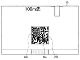
ここで、図6〜図8を参照して、上記の機能についてより詳細に説明する。図6〜図8はそれぞれ、マーカー20が撮影された撮影画像30の一例を示した説明図である。なお、図6、図7、図8の順に、マーカー20の撮影時においてカメラ168とマーカー20との間の距離が小さい、または、マーカー20に対してズームの倍率が大きくされた場合の例を示している。また、図6〜図8に示した例では、マーカー20は、図3の(b)に示したように、マーカー20a〜マーカー20cが重畳されて構成されていることを前提としている。
Here, the above functions will be described in more detail with reference to FIGS. FIG. 6 to FIG. 8 are explanatory diagrams showing an example of a captured
例えば、図6に示した例では、マーカー検出部102は、撮影画像30の中から黒枠およびドットパターンを探索することにより、マーカー20aを検出する。なお、マーカー20bまたはマーカー20cが撮影された領域に関しては、所定の数以上のドットが検出されないので、マーカー検出部102は、マーカー20bおよびマーカー20cを検出しない。
For example, in the example illustrated in FIG. 6, the
同様に、図7に示した例では、マーカー検出部102は、マーカー20aおよびマーカー20bを検出する。なお、マーカー20cが撮影された領域に関しては、所定の数以上のドットが検出されないので、マーカー検出部102は、マーカー20cを検出しない。
Similarly, in the example illustrated in FIG. 7, the
同様に、図8に示した例では、マーカー検出部102は、マーカー20a〜マーカー20cを検出する。
Similarly, in the example illustrated in FIG. 8, the
−色の特定
また、マーカー検出部102は、マーカー20の色を特定することも可能である。例えば、マーカー20の色が青色、赤色、緑色のいずれかであることが予め定められている場合には、マーカー検出部102は、まず、検出したマーカー20の黒枠の内部において、例えば青色の階調が所定の値以上であるドットを探索し、そして、例えば所定の数以上のドットが検出されるか否かを判定することにより、マーカー20の色が青色であるか否かを判定する。同様に、マーカー検出部102は、赤色または緑色に関しても、同様の処理を繰り返すことにより、マーカー20の色を特定する。
-Specification of color The
(2−1−2−3.マーカー認識部104)
マーカー認識部104は、マーカー検出部102により検出されたマーカー20の種類を認識する。より具体的には、マーカー認識部104は、検出されたマーカー20に記録されている情報を読み取る。
(2-1-2-3. Marker recognition unit 104)
The
例えば、マーカー認識部104は、まず、マーカー検出部102により検出されたマーカー20のドットパターンを特定する。そして、マーカー認識部104は、特定したドットパターンを所定のルールに従って文字列に変換することにより、マーカー20に記録されている情報を読み取る。
For example, the
(2−1−2−4.情報取得部106)
−取得例1
情報取得部106は、マーカー認識部104により認識されたマーカー20に対応づけられている複数の情報のうちいずれかを情報DB26−1から取得する。より具体的には、情報取得部106は、マーカー認識部104によりマーカー20から読み取られた情報、およびマーカー検出部102により特定されたマーカー20の色に対応する情報を情報DB26−1から取得する。なお、一枚の撮影画像において、同じ種類であって、かつサイズの異なる複数のマーカー20が検出された場合には、情報取得部106は、当該複数のマーカー20のうちいずれかから読み取られた情報、および当該複数のマーカー20のうちサイズが最も小さいマーカー20の色に対応する情報のみを情報DB26−1から取得してもよい。
(2-1-2-4. Information acquisition unit 106)
-Acquisition example 1
The
例えば、図7に示した例では、マーカー20aよりもマーカー20bの方がサイズが小さいので、情報取得部106は、マーカー20bから読み取られる「100」という文字列、およびマーカー20bの色である「赤」に対応づけられた情報(つまり、「BBB」)のみを情報DB26−1から取得する。
For example, in the example shown in FIG. 7, since the size of the
なお、変形例として、一枚の撮影画像において、同じ種類であって、かつサイズの異なる複数のマーカー20が検出された場合に、情報取得部106は、当該複数のマーカー20に対応する情報を全て情報DB26−1から取得することも可能である。
As a modification, when a plurality of
−取得例2
また、情報取得部106は、後述する操作認識部110により認識された操作内容に応じた情報をサーバ24から取得することも可能である。例えば、情報取得部106は、出力部126に出力される、後述するメニュー表示のうちいずれかに対するユーザの選択が操作認識部110により認識された場合には、ユーザにより選択されたメニュー表示に対する情報をサーバ24から取得する。
-Acquisition example 2
Further, the
(2−1−2−5.出力制御部108)
出力制御部108は、情報取得部106により取得された情報を、後述する出力部126に出力させる。例えば、出力制御部108は、情報取得部106により取得された情報を表示画面に重畳して表示させる。なお、表示画面は、例えば出力部126により表示されている画面である。また、例えばディスプレイがシースルー型である場合には、表示画面は、透明の画面であってもよい。
(2-1-2-5. Output control unit 108)
The
ここで、図9を参照して、上記の機能についてより詳細に説明する。図9は、図6に示した撮影画像30に関して、情報取得部106により取得された情報が表示画面に重畳して表示された例を示した説明図である。図9に示したように、出力制御部108は、情報取得部106によりマーカー20aに対応する情報として取得された「○○の周辺地図」という文字列400を表示画面に重畳して表示させる。なお、図9において一点鎖線で示した表示領域310は、表示画面において情報が重畳して表示される領域の一例を示している。
Here, the above function will be described in more detail with reference to FIG. FIG. 9 is an explanatory diagram showing an example in which the information acquired by the
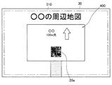
また、図10は、図7に示した撮影画像30に関して、情報取得部106により取得された情報が表示領域310に表示された例を示した説明図である。なお、図10では、便宜上、表示領域310のみを図示しており、(表示領域310の背景である)撮影画像30に関しては、図示を省略している。
FIG. 10 is an explanatory diagram showing an example in which information acquired by the
図10に示したように、出力制御部108は、情報取得部106によりマーカー20bに対応する情報として取得された、概要の地図を含む表示情報400、および「営業時間を調べる」のようなメニュー表示402を表示領域310に表示させる。
As illustrated in FIG. 10, the
ここで、メニュー表示402は、例えば入力部124に対する入力などにより、ウェアラブル端末10のユーザが選択可能な表示項目である。なお、メニュー表示402がユーザにより選択されると、選択されたメニュー表示402に対応する情報が情報取得部106によりサーバ24から取得され、そして、出力制御部108は、取得された情報を表示させたり、または音声により出力させる。例えば、出力制御部108は、現在表示領域310に表示されている情報を、取得された情報に置き換えて表示領域310に表示させたり、または、取得された情報を表示領域310に追加表示させる。
Here, the
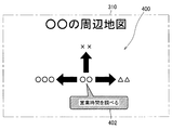
また、図11は、図8に示した撮影画像30に関して、情報取得部106により取得された情報が表示領域310に表示された例を示した説明図である。図11に示したように、出力制御部108は、情報取得部106によりマーカー20cに対応する情報として取得された、詳細な地図を含む表示情報400、およびメニュー表示402を表示領域310に表示させる。
FIG. 11 is an explanatory diagram showing an example in which the information acquired by the
図11に示した例では、例えば「開催中のイベント」(メニュー表示402b)や「おすすめ商品」(メニュー表示402c)など、図10と比べて、より多数のメニュー表示402が表示される。このため、ユーザは、より多くのメニュー表示402の中から、所望のメニュー表示402を選択することができる。
In the example shown in FIG. 11, for example, a larger number of menu displays 402 are displayed as compared to FIG. 10, such as “currently held event” (
(2−1−2−6.操作認識部110)
操作認識部110は、例えばユーザの視線の変化や、ユーザの音声などに基づいて、ユーザの操作内容を認識する。例えば、操作認識部110は、出力部126に出力されたメニュー表示のうちいずれかに対するユーザの選択操作を認識する。さらに、操作認識部110は、ユーザに選択されたメニュー表示を特定する。
(2-1-2-6. Operation recognition unit 110)
The
(2−1−2−7.通信部120)
通信部120は、通信網22を介して、通信網22に接続される装置との間で情報の送受信を行う。例えば、通信部120は、情報取得部106の制御により、マーカー20に対応づけられている情報の取得要求をサーバ24へ送信する。また、通信部120は、マーカー20に対応づけられている情報をサーバ24から受信する。
(2-1-2-7. Communication unit 120)
The
(2−1−2−8.撮影部122)
撮影部122は、ユーザの操作に応じて外環境を撮影し、そして、静止画像または動画像として記録する。
(2-1-2-8. Imaging unit 122)
The photographing
(2−1−2−9.入力部124)
入力部124は、ユーザによるウェアラブル端末10に対する各種の入力操作を受け付ける。例えば、入力部124は、ウェアラブル端末10が有する各種ボタンの入力や、ユーザの音声入力などを受け付ける。
(2-1-2-9. Input unit 124)
The
(2−1−2−10.出力部126)
出力部126は、出力制御部108の制御に従って、例えば情報取得部106により取得された情報を表示画面に表示したり、または、音声により出力する。
(2-1-2-10. Output unit 126)
The
(2−1−2−11.記憶部128)
記憶部128は、例えば撮影部122により撮影された撮影画像など、各種データを記憶する。
(2-1-2-11. Storage unit 128)
The
なお、第1の実施形態によるウェアラブル端末10の構成は、上述した構成に限定されない。例えば、入力部124、または記憶部128は、ウェアラブル端末10に含まれなくてもよい。そして、入力部124、または記憶部128は、ウェアラブル端末10と通信可能な他の装置に備えられてもよい。
Note that the configuration of the
[2−1−3.動作]
以上、第1の実施形態による構成について説明した。続いて、第1の実施形態による動作について説明する。
[2-1-3. Operation]
The configuration according to the first embodiment has been described above. Subsequently, an operation according to the first embodiment will be described.
図12は、第1の実施形態による動作を示したシーケンス図である。図12に示したように、まず、ウェアラブル端末10の撮影部122は、例えばユーザの操作に応じて外環境を撮影する(S101)。
FIG. 12 is a sequence diagram showing an operation according to the first embodiment. As shown in FIG. 12, first, the
続いて、マーカー検出部102は、S101で撮影された撮影画像に含まれるマーカー20を検出する。さらに、マーカー検出部102は、検出したマーカー20の色を特定する(S102)。
Subsequently, the
続いて、マーカー認識部104は、S102で検出されたマーカー20に記録されている情報を読み取る(S103)。
Subsequently, the
続いて、情報取得部106は、S103で読み取られた情報、およびS102で特定されたマーカー20の色に対応する情報の取得要求をサーバ24へ通信部120に送信させる(S104)。
Subsequently, the
その後、サーバ24は、S104で受信された取得要求に基づいて、該当の情報を情報DB26−1から抽出する(S105)。そして、サーバ24は、抽出した情報をウェアラブル端末10へ送信する(S106)。
Thereafter, the
その後、ウェアラブル端末10の出力制御部108は、S106で受信された情報を例えば表示画面に重畳して表示させるなど、出力部126に出力させる(S107)。
Thereafter, the
その後、ユーザは、S107で出力されたメニュー表示のうち、所望のメニュー表示を例えば視線の変化、発声、またはボタンの押下などにより選択する(S108)。 Thereafter, the user selects a desired menu display from among the menu displays output in S107, for example, by changing the line of sight, speaking, or pressing a button (S108).
続いて、情報取得部106は、S108で選択されたメニュー表示に対応する情報の取得要求をサーバ24へ通信部120に送信させる(S109)。
Subsequently, the
その後、サーバ24は、S109で受信された取得要求に対応する情報を例えば記憶装置から取得する。そして、サーバ24は、取得した情報をウェアラブル端末10へ送信する(S110)。
Thereafter, the
その後、ウェアラブル端末10の出力制御部108は、S110で受信された情報を例えば表示画面に表示させたり、または音声出力させるなど、出力部126に出力させる(S111)。
Thereafter, the
[2−1−4.効果]
以上、例えば図5、および図12等を参照して説明したように、第1の実施形態によるウェアラブル端末10は、撮影画像に含まれるマーカー20を検出し、検出されたマーカー20から読み取られる情報、およびマーカー20の色に基づいて、マーカー20に対応づけられている複数の情報のうちいずれかをサーバ24から取得し、そして、取得された情報を出力させる。また、マーカー20の色は、マーカー20のサイズと対応づけて予め決められている。このため、第1の実施形態によれば、撮影時のユーザとマーカー20との間の距離に応じて、出力させる情報を変化させることができる。
[2-1-4. effect]
As described above, for example, as described with reference to FIGS. 5 and 12, the
例えば、ウェアラブル端末10は、より小さいサイズのマーカー20に対応する色のマーカー20が読み取られた場合には、より詳細な情報をサーバ24から取得する。このため、撮影時のユーザとマーカー20との間の距離が小さいほど、より詳細な情報を出力させることができる。つまり、マーカー20が貼られた物体にユーザが興味を持ち、当該物体に近づくにつれて、より詳細な情報をユーザに提示することが可能となる。
For example, the
また、出力された複数のメニュー表示のうち所望のメニュー表示を選択することにより、ユーザは、例えば、さらに知りたい情報を容易に出力させたり、または、関心のあるサービスを容易に利用することができる。 Further, by selecting a desired menu display from among the plurality of output menu displays, for example, the user can easily output information he or she wants to know or can easily use a service of interest. it can.
<2−2.第2の実施形態>
以上、第1の実施形態について説明した。上述したように、第1の実施形態では、ウェアラブル端末10は、検出されたマーカー20の色に基づいて、異なる情報をサーバ24から取得する。
<2-2. Second Embodiment>
The first embodiment has been described above. As described above, in the first embodiment, the
次に、第2の実施形態について説明する。後述するように、第2の実施形態によれば、ウェアラブル端末10は、マーカー20に対するユーザの注目度に基づいて、異なる情報をサーバ24から取得することが可能である。
Next, a second embodiment will be described. As will be described later, according to the second embodiment, the
[2−2−1.基本構成]
まず、第2の実施形態による情報処理システムの基本構成について説明する。なお、第2の実施形態による情報処理システムが有する構成要素は、図2に示した第1の実施形態と同様である。以下では、第1の実施形態と内容が異なる構成要素についてのみ説明を行う。
[2-2-1. Basic configuration]
First, the basic configuration of the information processing system according to the second embodiment will be described. The constituent elements of the information processing system according to the second embodiment are the same as those of the first embodiment shown in FIG. Hereinafter, only components that are different from those in the first embodiment will be described.
(2−2−1−1.マーカー20)
第2の実施形態では、マーカー20は、基本的には、図3の(a)に示したように、個々のマーカー20が独立して構成されている、つまり、複数のマーカー20が重畳されずに構成されていることを想定する。
(2-2-1-1. Marker 20)
In the second embodiment, as shown in FIG. 3A, the
但し、かかる例に限定されず、複数のマーカー20が重畳されて構成される例に関しても、第2の実施形態は概略同様に適用可能である。
However, the present invention is not limited to such an example, and the second embodiment can be applied in a similar manner to an example in which a plurality of
(2−2−1−2.サーバ24)
第2の実施形態によるサーバ24は、情報DB26−1の代わりに、図13に示したような、情報DB26−2を管理する。情報DB26−2は、マーカー20の種類および撮影画像におけるマーカー20の占有領域に関する情報に対応づけて情報が登録されるデータベースである。
(2-2-1-2. Server 24)
The
ここで、マーカー20の占有領域に関する情報とは、例えば、撮影画像におけるマーカー20の占有領域の占有度、または、撮影画像におけるマーカー20の位置などを含む情報である。また、マーカー20の占有領域の占有度とは、例えば、撮影画像におけるマーカー20のサイズ、または、撮影画像におけるマーカー20の撮影時間の長さを含む。例えば、マーカー20の占有領域に関する情報は、撮影画像におけるマーカー20の位置、および撮影画像におけるマーカー20の撮影時間の長さの組み合わせの情報であってもよい。
Here, the information related to the occupied area of the
−情報DB26−2
ここで、図13を参照して、情報DB26−2の構成例について説明する。図13に示したように、情報DB26−2は、例えば、インデックス260、位置272、サイズ274、撮影時間276、および情報内容264が対応づけて記録される。なお、インデックス260、および情報内容264は、第1の実施形態による情報DB26−1と同様である。
-Information DB 26-2
Here, a configuration example of the information DB 26-2 will be described with reference to FIG. As shown in FIG. 13, in the information DB 26-2, for example, an
ここで、位置272には、撮影画像におけるマーカー20の相対的な位置が記録される。また、サイズ274には、撮影画像におけるマーカー20の相対的なサイズが記録される。また、撮影時間276には、マーカー20の撮影時間の長さが記録される。
Here, in the
例えば、図13の2レコード目に示したデータは、マーカー20に記録されている情報が「100」であり、撮影画像における位置が「周辺」であり、撮影画像におけるサイズが「中」であるマーカー20には、「AAA」という情報が対応づけて登録されていること、また、「AAA」という情報のカテゴリは「地図」であり、階層は「上位」であることをそれぞれ示している。
For example, in the data shown in the second record in FIG. 13, the information recorded in the
[2−2−2.構成]
以上、第2の実施形態による基本構成について説明した。次に、第2の実施形態による構成について詳細に説明する。なお、第2の実施形態によるウェアラブル端末10が有する構成要素は、第1の実施形態と同様である。以下では、第1の実施形態と異なる機能を有する構成要素についてのみ説明を行う。
[2-2-2. Constitution]
The basic configuration according to the second embodiment has been described above. Next, the configuration according to the second embodiment will be described in detail. In addition, the component which the
(2−2−2−1.マーカー検出部102)
第2の実施形態によるマーカー検出部102は、検出したマーカー20に関して、撮影画像における占有領域に関する情報を特定することが可能である。
(2-2-1. Marker detection unit 102)
The
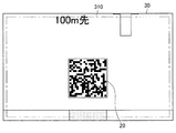
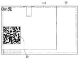
ここで、図14〜図17を参照して、上記の機能についてより詳細に説明する。図14〜図17はそれぞれ、マーカー20が撮影された撮影画像30の一例を示した説明図である。なお、図14、図15、図16(または図17)の順に、マーカー20の撮影時においてカメラ168とマーカー20との間の距離が小さい、または、マーカー20に対してズームの倍率が大きくされた場合の撮影画像30の例を示している。
Here, the above functions will be described in more detail with reference to FIGS. FIG. 14 to FIG. 17 are explanatory diagrams showing an example of a captured
例えば、図14に示した例では、マーカー検出部102は、検出したマーカー20に関して、撮影画像30の対角線の中心から所定の範囲内に、マーカー20の撮影領域の対角線の中心が含まれているか否かを判定することにより、撮影画像におけるマーカー20の位置を「中央」と特定する。また、マーカー検出部102は、撮影画像30におけるマーカー20の相対的なサイズを算出することにより、撮影画像におけるマーカー20のサイズを「小」と特定する。
For example, in the example illustrated in FIG. 14, for the detected
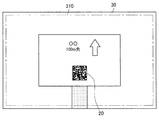
同様に、図15に示した例では、マーカー検出部102は、撮影画像におけるマーカー20の位置は「中央」であり、撮影画像におけるマーカー20のサイズは「中」であると特定する。
Similarly, in the example illustrated in FIG. 15, the
同様に、図16に示した例では、マーカー検出部102は、撮影画像におけるマーカー20の位置は「中央」であり、撮影画像におけるマーカー20のサイズは「大」であると特定する。
Similarly, in the example illustrated in FIG. 16, the
同様に、図17に示した例では、マーカー検出部102は、撮影画像におけるマーカー20の位置は「周辺」であり、撮影画像におけるマーカー20のサイズは「大」であると特定する。
Similarly, in the example illustrated in FIG. 17, the
また、マーカー検出部102は、例えば、撮影された動画像において、マーカー20が検出されたフレームの枚数を算出することにより、撮影画像におけるマーカー20の撮影時間の長さを特定する。なお、マーカー検出部102は、マーカー20が検出された、連続したフレームの枚数を算出することにより、マーカー20の撮影時間の長さを特定してもよい。
In addition, the
図18は、マーカー20が撮影された動画像の一例を示した説明図である。なお、図18では、フレーム画像30b〜フレーム画像30fに関してはマーカー20が検出され、また、フレーム画像30aおよびフレーム画像30gに関してはマーカー20が検出されなかった例を示している。
FIG. 18 is an explanatory diagram illustrating an example of a moving image in which the
例えば、図18に示した例では、マーカー検出部102は、マーカー20が検出されたフレームの枚数を5枚と算出し、そして、算出したフレームの枚数に動画像のフレームレートを乗じることにより、マーカー20の撮影時間の長さを特定する。
For example, in the example illustrated in FIG. 18, the
(2−2−2−2.情報取得部106)
第2の実施形態による情報取得部106は、マーカー認識部104によりマーカー20から読み取られた情報、およびマーカー検出部102により特定された、マーカー20の占有領域に関する情報に対応づけられた情報を情報DB26−2から取得する。例えば、情報取得部106は、撮影画像におけるマーカー20の占有領域の占有度が大きいほど、マーカー20に対応づけられている複数の情報のうち階層がより下位の情報を情報DB26−2から取得する。または、情報取得部106は、撮影画像におけるマーカー20の占有領域の占有度が大きいほど、マーカー20に対応づけられている複数の情報のうち情報量がより多い情報を情報DB26−2から取得する。
(2-2-2-2. Information Acquisition Unit 106)
The
例えば、図14〜図16に示した例において、マーカー検出部102により、撮影画像30におけるマーカー20のサイズがそれぞれ「小」、「中」、「大」であり、かつ、マーカー20の位置は全て「中央」であると判定されたとする。この場合には、情報取得部106は、図14〜図16に示した例に関してそれぞれ、階層が「上位」、「中位」、「下位」である情報を、図13に示した情報DB26−2から取得する。
For example, in the examples illustrated in FIGS. 14 to 16, the size of the
また、情報取得部106は、マーカー20の占有領域に関する情報に基づいて、マーカー20に対応づけて情報DB26−2に登録されている複数の情報のうち、カテゴリが異なる情報を情報DB26−2から取得することも可能である。
Further, the
[2−2−3.適用例]
以上、第2の実施形態による構成について説明した。ここで、図19〜図24を参照して、上述した第2の実施形態の適用例について説明する。
[2-2-3. Application example]
The configuration according to the second embodiment has been described above. Here, an application example of the above-described second embodiment will be described with reference to FIGS.
図19は、マーカー20が貼られた看板2の一例を示した説明図である。図19に示したように、看板2は、4個の区画に分割されており、また、それぞれの区画には、「飲食店のご案内」、「観光地のご案内」、「宿泊先のご案内」、または「交通機関のご案内」と記載されている。また、看板2の中心において、4個の区画とそれぞれ一部の領域が重なるようにマーカー20が貼られている。なお、マーカー20には、「200」という情報が記録されていることを前提とする。
FIG. 19 is an explanatory diagram showing an example of the
図20は、図19に示したマーカー20に対応づけて情報DB26−2に登録されている情報の例を示した説明図である。図20に示したように、情報DB26−2には、撮影画像におけるマーカー20の位置が「右下」、「左下」、「右上」、「左上」のいずれかによって、それぞれ異なるカテゴリの情報が対応づけて登録されている。例えば、マーカー20のサイズが「中」または「大」である場合、撮影画像における位置が「右下」であるマーカー20に対応づけられている情報のカテゴリは「飲食店案内」であるのに対し、撮影画像における位置が「左下」であるマーカー20に対応づけられている情報のカテゴリは「観光地案内」である。
FIG. 20 is an explanatory diagram showing an example of information registered in the information DB 26-2 in association with the
(2−2−3−1.撮影例1)
図21は、看板2に貼られているマーカー20が撮影された撮影画像30の例を示した説明図である。この図21に示した例では、マーカー検出部102は、例えば、撮影画像30におけるマーカー20の位置は「左上」であり、また、撮影画像30におけるマーカー20のサイズは「中」であると特定する。
(2-2-3-1. Photographing Example 1)
FIG. 21 is an explanatory diagram illustrating an example of a captured
この場合には、情報取得部106は、検出されたマーカー20に対応する情報として、カテゴリが「交通機関案内」であり、階層が「中位」である情報(「XD1」)を情報DB26−2から取得する。
In this case, the
また、図22は、情報取得部106により取得された情報が出力制御部108により表示領域310に表示された例を示した説明図である。図22に示したように、例えば、「交通機関のご案内」という文字列400、および「バス」、「電車」、「タクシー」などのメニュー表示402が表示される。
FIG. 22 is an explanatory diagram showing an example in which the information acquired by the
(2−2−3−2.撮影例2)
また、図23は、図21に示した例よりも、例えばカメラ168をマーカー20に近づけて撮影されることにより、マーカー20がより大きく撮影された撮影画像30の例を示した説明図である。この図23に示した例では、マーカー検出部102は、撮影画像30におけるマーカー20の位置は「左上」であり、また、撮影画像30におけるマーカー20のサイズは「大」であると特定する。
(2-2-3-2. Photographing Example 2)
FIG. 23 is an explanatory diagram illustrating an example of a captured
この場合には、情報取得部106は、検出されたマーカー20に対応する情報として、カテゴリが「交通機関案内」であり、階層が「下位」である情報(「XD2」)を情報DB26−2から取得する。
In this case, as the information corresponding to the detected
また、図24は、情報取得部106により取得された情報が出力制御部108により表示領域310に表示された例を示した説明図である。図24に示したように、例えば「○○方面のバス時刻表」や「○×方面のバス時刻表」など、図22と比べて、階層がより下位で、かつ、より詳細な内容のメニュー表示402が表示される。
FIG. 24 is an explanatory diagram showing an example in which the information acquired by the
図22および図24に示した表示例によれば、マーカー20が貼られている物体に対するユーザの注目度が大きいほど、より詳細な情報や、より詳細な内容のメニューを表示させることが可能となる。さらには、当該物体においてユーザが見ている範囲によって、異なるカテゴリの情報を表示させることが可能となる。このため、マーカー20が貼られている物体にユーザが近づくにつれて、より詳細な情報や、当該物体においてユーザが注目している内容の情報をユーザに提示することが可能となる。
According to the display examples shown in FIG. 22 and FIG. 24, it is possible to display a menu with more detailed information and more detailed contents as the degree of attention of the user with respect to the object to which the
[2−2−4.動作]
以上、第2の実施形態による構成について説明した。続いて、第2の実施形態による動作について説明する。
[2-2-4. Operation]
The configuration according to the second embodiment has been described above. Subsequently, an operation according to the second embodiment will be described.
図25は、第2の実施形態による動作を示したシーケンス図である。なお、図25に示したS201の動作は、図12に示したS101と同様である。 FIG. 25 is a sequence diagram showing an operation according to the second embodiment. The operation of S201 shown in FIG. 25 is the same as that of S101 shown in FIG.
S201の後、マーカー検出部102は、S201で撮影された撮影画像に含まれるマーカー20を検出する。さらに、マーカー検出部102は、撮影画像におけるマーカー20の位置、撮影画像におけるマーカー20のサイズ、または、撮影画像におけるマーカー20の撮影時間の長さなどを特定する(S202)。
After S201, the
S203の動作は、図12に示したS103と同様である。 The operation in S203 is the same as that in S103 shown in FIG.
S203の後、情報取得部106は、S203で読み取られた情報、および、S202で特定されたマーカー20の位置、サイズ、または撮影時間の長さなどに対応する情報の取得要求をサーバ24へ通信部120に送信させる(S204)。
After S203, the
なお、S205〜S211の動作は、図12に示したS105〜S111と概略同様である。 In addition, the operation | movement of S205-S211 is as substantially the same as S105-S111 shown in FIG.
[2−2−5.効果]
以上、例えば図25等を参照して説明したように、第2の実施形態によるウェアラブル端末10は、撮影画像に含まれるマーカー20を検出し、検出されたマーカー20から読み取られる情報、および撮影画像におけるマーカー20の占有領域に関する情報に基づいて、マーカー20に対応づけられている複数の情報のうちいずれかをサーバ24から取得し、そして、取得した情報を出力させる。
[2-2-5. effect]
As described above, for example, as described with reference to FIG. 25 and the like, the
例えば、ウェアラブル端末10は、マーカー20が貼られている物体に対するユーザの注目度がより大きい(と推測される)場合には、より具体的であったり、より内容の多い情報やメニューを出力させる。さらには、当該物体においてユーザが見ている範囲によって、異なるカテゴリの情報や、(カテゴリが同じであっても)異なる内容の情報を表示させる。このため、マーカー20が貼られている物体にユーザが近づくにつれて、より詳細な情報や、当該物体においてユーザが注目している内容の情報をユーザに提示することが可能となる。
For example, the
<<3.ハードウェア構成>>
以上、本発明の各実施形態について説明した。次に、各実施形態に共通するウェアラブル端末10のハードウェア構成について、図26を参照して説明する。図26に示したように、ウェアラブル端末10は、CPU150、ROM(Read Only Memory)152、RAM154、内部バス156、入出力インターフェース158、入力装置160、出力装置162、HDD(Hard Disk Drive)164、ネットワークインターフェース166、およびカメラ168を備える。
<< 3. Hardware configuration >>
The embodiments of the present invention have been described above. Next, the hardware configuration of the
<3−1.CPU150>
CPU150は、演算処理装置および制御装置として機能し、各種プログラムに従ってウェアラブル端末10内の動作全般を制御する。また、CPU150は、ウェアラブル端末10において制御部100の機能を実現する。なお、CPU150は、マイクロプロセッサなどのプロセッサにより構成される。
<3-1.
The
<3−2.ROM152>
ROM152は、CPU150が使用するプログラムや演算パラメータ等を記憶する。
<3-2. ROM152>
The
<3−3.RAM154>
RAM154は、CPU150の実行において使用するプログラムや、その実行において適宜変化するパラメータ等を一時記憶する。
<3-3. RAM154>
The
<3−4.内部バス156>
内部バス156は、CPUバスなどから構成される。この内部バス156は、CPU150、ROM152、およびRAM154を相互に接続する。
<3-4.
The
<3−5.入出力インターフェース158>
入出力インターフェース158は、HDD164、およびネットワークインターフェース166を、内部バス156と接続する。例えばHDD164は、この入出力インターフェース158および内部バス156を介して、RAM154などとの間でデータをやり取りする。
<3-5. Input /
The input /
<3−6.入力装置160>
入力装置160は、入力部124の一例として構成される。入力装置160は、例えばボタン、マイクロフォン、およびスイッチなどユーザが情報を入力するための入力手段と、ユーザによる入力に基づいて入力信号を生成し、CPU150に出力する入力制御回路などから構成されている。
<3-6.
The
<3−7.出力装置162>
出力装置162は、出力部126の一例として構成される。出力装置162は、例えば、液晶ディスプレイ(LCD:Liquid Crystal Display)装置、OLED(Organic Light Emitting Diode)装置およびランプなどの表示装置を含む。この表示装置は、カメラ168により撮影された画像や、CPU150により生成された画像などを表示する。
<3-7.
The
さらに、出力装置162は、スピーカーなどの音声出力装置を含む。この音声出力装置は、音声データ等を音声に変換して出力する。
Further, the
<3−8.HDD164>
HDD164は、記憶部128として機能する、データ格納用の装置である。このHDD164は、例えば、記憶媒体、記憶媒体にデータを記録する記録装置、記憶媒体からデータを読み出す読出し装置、および記憶媒体に記録されたデータを削除する削除装置などを含む。また、HDD164は、CPU150が実行するプログラムや各種データを格納する。
<3-8. HDD164>
The
<3−9.ネットワークインターフェース166>
ネットワークインターフェース166は、例えばインターネットなどの通信網に接続するための通信デバイス等で構成された通信インターフェースである。このネットワークインターフェース166は、通信部120として機能する。なお、ネットワークインターフェース166は、無線LAN対応通信装置、LTE(Long Term Evolution)対応通信装置、または有線による通信を行うワイヤー通信装置であってもよい。
<3-9.
The
<3−10.カメラ168>
カメラ168は、撮影部122の一例として構成される。カメラ168は、外部の映像を、レンズを通して例えばCCD(Charge Coupled Device)やCMOS(Complementary Metal Oxide Semiconductor)などの撮像素子に結像させ、静止画像または動画像を撮影する機能を有する。
<3-10.
The
<<4.変形例>>
なお、添付図面を参照しながら本発明の好適な実施形態について詳細に説明したが、本発明はかかる例に限定されない。本発明の属する技術の分野における通常の知識を有する者であれば、特許請求の範囲に記載された技術的思想の範疇内において、各種の変更例または修正例に想到し得ることは明らかであり、これらについても、当然に本発明の技術的範囲に属するものと了解される。
<< 4. Modification >>
Although the preferred embodiments of the present invention have been described in detail with reference to the accompanying drawings, the present invention is not limited to such examples. It is obvious that a person having ordinary knowledge in the technical field to which the present invention pertains can come up with various changes or modifications within the scope of the technical idea described in the claims. Of course, it is understood that these also belong to the technical scope of the present invention.
<4−1.変形例1>
例えば、上述した各実施形態では、本発明における情報処理装置がウェアラブル端末10である例について説明したが、かかる例に限定されない。例えば、本発明における情報処理装置は、スマートフォンなどの携帯電話、タブレット端末、またはゲーム機などの携帯型端末であってもよい。
<4-1.
For example, in each of the above-described embodiments, the example in which the information processing apparatus according to the present invention is the
<4−2.変形例2>
また、マーカー20の撮影時においてマーカー20の一部が撮影範囲から外れている場合には、ウェアラブル端末10は、例えば「(マーカーを撮影するために)カメラを右側へずらして下さい」のようなメッセージを出力させることも可能である。この変形例2によれば、仮にユーザが物体に注目している場合であっても、偶然マーカー20がカメラ168の撮影範囲から一部外れてしまうことにより、マーカー20から情報を取得できないという事象が発生することを抑止することができる。
<4-2.
In addition, when a part of the
また、例えば図17に示したように、撮影画像におけるマーカー20の位置が「周辺」である場合に関しても、ウェアラブル端末10は、マーカー20の位置が「中央」になるように、カメラ168を移動させるように促すメッセージを出力させることが可能である。
For example, as shown in FIG. 17, even when the position of the
<4−3.変形例3>
また、上述した各実施形態では、ウェアラブル端末10がマーカー20から情報を読み取る例について説明したが、かかる例に限定されない。例えば、マーカー20の代わりに、電波強度の異なる2つ以上のRFIDタグなど、情報の読み取り距離が異なる2つ以上の物体からウェアラブル端末10は情報を読み取ってもよい。
<4-3. Modification 3>
Moreover, although each embodiment mentioned above demonstrated the example in which the
<4−4.変形例4>
また、各実施形態によれば、CPU150、ROM152、およびRAM154などのハードウェアを、上述したウェアラブル端末10の各構成と同等の機能を発揮させるためのコンピュータプログラムも提供可能である。また、該コンピュータプログラムが記録された記録媒体も提供される。
<4-4. Modification 4>
In addition, according to each embodiment, it is also possible to provide a computer program for causing hardware such as the
10 ウェアラブル端末
20 マーカー
22 通信網
24 サーバ
26−1、26−2 情報DB
100 制御部
102 マーカー検出部
104 マーカー認識部
106 情報取得部
108 出力制御部
110 操作認識部
120 通信部
122 撮影部
124 入力部
126 出力部
128 記憶部
150 CPU
152 ROM
154 RAM
156 内部バス
158 入出力インターフェース
160 入力装置
162 出力装置
164 HDD
166 ネットワークインターフェース
168 カメラ
10
DESCRIPTION OF
152 ROM
154 RAM
156
Claims (10)
検出されたマーカーの前記撮影画像における占有領域に関する情報に基づいて、前記マーカーに対応づけられている複数の情報のうちいずれかを取得する情報取得部と、
取得された情報の出力を制御する出力制御部と、
を備える、情報処理装置。 A marker detection unit for detecting a marker included in the captured image;
An information acquisition unit that acquires any one of a plurality of pieces of information associated with the marker based on information about an occupied area in the captured image of the detected marker;
An output control unit for controlling the output of the acquired information;
An information processing apparatus comprising:
前記情報取得部は、さらに、検出されたマーカーの色に基づいて、前記マーカーに対応づけられている前記複数の情報のうちいずれかを取得する、請求項1〜7のいずれか一項に記載の情報処理装置。 One or more markers of different colors and sizes are superimposed on the marker,
The said information acquisition part further acquires any one among these several information matched with the said marker based on the color of the detected marker. Information processing device.
検出されたマーカーの前記撮影画像における占有領域に関する情報に基づいて、前記マーカーに対応づけられている複数の情報のうちいずれかを取得するステップと、
取得された情報の出力を制御するステップと、
を備える、情報処理方法。 Detecting a marker included in the captured image;
Acquiring any one of a plurality of pieces of information associated with the marker based on information about the occupied area in the captured image of the detected marker;
Controlling the output of the acquired information;
An information processing method comprising:
撮影画像に含まれるマーカーを検出するマーカー検出部と、
検出されたマーカーの前記撮影画像における占有領域に関する情報に基づいて、前記マーカーに対応づけられている複数の情報のうちいずれかを取得する情報取得部と、
取得された情報の出力を制御する出力制御部と、
として機能させるための、プログラム。 Computer
A marker detection unit for detecting a marker included in the captured image;
An information acquisition unit that acquires any one of a plurality of pieces of information associated with the marker based on information about an occupied area in the captured image of the detected marker;
An output control unit for controlling the output of the acquired information;
Program to function as
Priority Applications (1)
| Application Number | Priority Date | Filing Date | Title |
|---|---|---|---|
| JP2014140420A JP2016018367A (en) | 2014-07-08 | 2014-07-08 | Information processing apparatus, information processing method, and program |
Applications Claiming Priority (1)
| Application Number | Priority Date | Filing Date | Title |
|---|---|---|---|
| JP2014140420A JP2016018367A (en) | 2014-07-08 | 2014-07-08 | Information processing apparatus, information processing method, and program |
Publications (1)
| Publication Number | Publication Date |
|---|---|
| JP2016018367A true JP2016018367A (en) | 2016-02-01 |
Family
ID=55233553
Family Applications (1)
| Application Number | Title | Priority Date | Filing Date |
|---|---|---|---|
| JP2014140420A Pending JP2016018367A (en) | 2014-07-08 | 2014-07-08 | Information processing apparatus, information processing method, and program |
Country Status (1)
| Country | Link |
|---|---|
| JP (1) | JP2016018367A (en) |
Cited By (4)
| Publication number | Priority date | Publication date | Assignee | Title |
|---|---|---|---|---|
| JP2018160063A (en) * | 2017-03-22 | 2018-10-11 | 株式会社スクウェア・エニックス | Information processing program, information processing device, and information processing method |
| JP2019079254A (en) * | 2017-10-24 | 2019-05-23 | 清水建設株式会社 | Information communication system, information medium, and reading device |
| WO2020031795A1 (en) * | 2018-08-07 | 2020-02-13 | ソニー株式会社 | Information processing device, information processing method, and program |
| JP2021043752A (en) * | 2019-09-12 | 2021-03-18 | 株式会社日立システムズ | Information display device, information display method, and information display system |
Citations (9)
| Publication number | Priority date | Publication date | Assignee | Title |
|---|---|---|---|---|
| JP2002247602A (en) * | 2001-02-15 | 2002-08-30 | Mixed Reality Systems Laboratory Inc | Image generator and control method therefor, and its computer program |
| WO2010073616A1 (en) * | 2008-12-25 | 2010-07-01 | パナソニック株式会社 | Information displaying apparatus and information displaying method |
| JP2010238098A (en) * | 2009-03-31 | 2010-10-21 | Ntt Docomo Inc | Terminal device, information presentation system, and terminal screen display method |
| JP2012018605A (en) * | 2010-07-09 | 2012-01-26 | Hitachi Systems Ltd | Maintenance/monitoring system using augmented reality technique |
| JP2012164157A (en) * | 2011-02-07 | 2012-08-30 | Toyota Motor Corp | Image synthesizer |
| WO2012144770A2 (en) * | 2011-04-19 | 2012-10-26 | Samsung Electronics Co., Ltd. | Method for displaying status of power consumption and portable device thereof |
| JP2012221250A (en) * | 2011-04-08 | 2012-11-12 | Sony Corp | Image processing system, display control method and program |
| JP2013218597A (en) * | 2012-04-11 | 2013-10-24 | Sony Corp | Information processing apparatus, display control method, and program |
| JP2014513836A (en) * | 2011-04-21 | 2014-06-05 | マイクロソフト コーポレーション | Color channel and light marker |
-
2014
- 2014-07-08 JP JP2014140420A patent/JP2016018367A/en active Pending
Patent Citations (9)
| Publication number | Priority date | Publication date | Assignee | Title |
|---|---|---|---|---|
| JP2002247602A (en) * | 2001-02-15 | 2002-08-30 | Mixed Reality Systems Laboratory Inc | Image generator and control method therefor, and its computer program |
| WO2010073616A1 (en) * | 2008-12-25 | 2010-07-01 | パナソニック株式会社 | Information displaying apparatus and information displaying method |
| JP2010238098A (en) * | 2009-03-31 | 2010-10-21 | Ntt Docomo Inc | Terminal device, information presentation system, and terminal screen display method |
| JP2012018605A (en) * | 2010-07-09 | 2012-01-26 | Hitachi Systems Ltd | Maintenance/monitoring system using augmented reality technique |
| JP2012164157A (en) * | 2011-02-07 | 2012-08-30 | Toyota Motor Corp | Image synthesizer |
| JP2012221250A (en) * | 2011-04-08 | 2012-11-12 | Sony Corp | Image processing system, display control method and program |
| WO2012144770A2 (en) * | 2011-04-19 | 2012-10-26 | Samsung Electronics Co., Ltd. | Method for displaying status of power consumption and portable device thereof |
| JP2014513836A (en) * | 2011-04-21 | 2014-06-05 | マイクロソフト コーポレーション | Color channel and light marker |
| JP2013218597A (en) * | 2012-04-11 | 2013-10-24 | Sony Corp | Information processing apparatus, display control method, and program |
Non-Patent Citations (1)
| Title |
|---|
| 工藤康之,外1名: ""博物館における収蔵物管理作業支援システム"", 電子情報通信学会技術研究報告, vol. 112, no. 475, JPN6018049522, 2013, pages 263 - 268, ISSN: 0003940803 * |
Cited By (6)
| Publication number | Priority date | Publication date | Assignee | Title |
|---|---|---|---|---|
| JP2018160063A (en) * | 2017-03-22 | 2018-10-11 | 株式会社スクウェア・エニックス | Information processing program, information processing device, and information processing method |
| JP2019079254A (en) * | 2017-10-24 | 2019-05-23 | 清水建設株式会社 | Information communication system, information medium, and reading device |
| WO2020031795A1 (en) * | 2018-08-07 | 2020-02-13 | ソニー株式会社 | Information processing device, information processing method, and program |
| US12033380B2 (en) | 2018-08-07 | 2024-07-09 | Sony Corporation | Information processing apparatus and information processing method |
| JP2021043752A (en) * | 2019-09-12 | 2021-03-18 | 株式会社日立システムズ | Information display device, information display method, and information display system |
| JP7419003B2 (en) | 2019-09-12 | 2024-01-22 | 株式会社日立システムズ | Information display device, information display method, and information display system |
Similar Documents
| Publication | Publication Date | Title |
|---|---|---|
| US11714523B2 (en) | Digital image tagging apparatuses, systems, and methods | |
| US9055276B2 (en) | Camera having processing customized for identified persons | |
| US8913885B2 (en) | Information provision system, server, terminal device, information provision method, display control method and recording medium | |
| US9253408B2 (en) | Photographing device, photographing device controlling method, photographing device controlling program, and computer-readable recording medium in which photographing device controlling program is recorded | |
| US10083351B2 (en) | Control system and control method | |
| US20130027569A1 (en) | Camera having processing customized for recognized persons | |
| US20130120602A1 (en) | Taking Photos With Multiple Cameras | |
| US20110043642A1 (en) | Method for providing object information and image pickup device applying the same | |
| JP6098318B2 (en) | Image processing apparatus, image processing method, image processing program, and recording medium | |
| WO2014030407A1 (en) | Control device and storage medium | |
| TW201535233A (en) | Note capture and recognition with manual assist | |
| JP2016018367A (en) | Information processing apparatus, information processing method, and program | |
| JP2014067131A (en) | Image processing apparatus, image processing system, image processing method, and computer program | |
| WO2015145769A1 (en) | Imaging device, information processing device, photography assistance system, photography assistance program, and photography assistance method | |
| CN104255022B (en) | Server, client terminal, system and the readable medium of virtual zoom capabilities are added for camera | |
| KR20150058871A (en) | Photographing device and stitching method of photographing image | |
| WO2016002306A1 (en) | Information processing system, information processing terminal, and information processing method | |
| JP2010021721A (en) | Camera | |
| CN104903769B (en) | Image processing apparatus, camera head and image processing method | |
| JP2008269411A (en) | Image keyword editing system, image keyword provision server and image keyword editing device | |
| WO2016080088A1 (en) | Imaging device and control method therefor | |
| JP2010252266A (en) | Image arrangement apparatus | |
| US20160173731A1 (en) | Image processing apparatus, data registration method, and data registration program | |
| CN104871532B (en) | Filming apparatus and its method of controlling operation | |
| WO2016088477A1 (en) | Information processing device, information processing method, and program |
Legal Events
| Date | Code | Title | Description |
|---|---|---|---|
| A621 | Written request for application examination |
Free format text: JAPANESE INTERMEDIATE CODE: A621 Effective date: 20170515 |
|
| A977 | Report on retrieval |
Free format text: JAPANESE INTERMEDIATE CODE: A971007 Effective date: 20180515 |
|
| A131 | Notification of reasons for refusal |
Free format text: JAPANESE INTERMEDIATE CODE: A131 Effective date: 20180529 |
|
| A521 | Request for written amendment filed |
Free format text: JAPANESE INTERMEDIATE CODE: A523 Effective date: 20180726 |
|
| A02 | Decision of refusal |
Free format text: JAPANESE INTERMEDIATE CODE: A02 Effective date: 20181218 |