JP2016015672A - Network control device and network setting system - Google Patents

Network control device and network setting system Download PDF

Info

Publication number
JP2016015672A
JP2016015672A JP2014137549A JP2014137549A JP2016015672A JP 2016015672 A JP2016015672 A JP 2016015672A JP 2014137549 A JP2014137549 A JP 2014137549A JP 2014137549 A JP2014137549 A JP 2014137549A JP 2016015672 A JP2016015672 A JP 2016015672A
Authority
JP
Japan
Prior art keywords
setting
network
network setting
variable
communication device
Prior art date
Legal status (The legal status is an assumption and is not a legal conclusion. Google has not performed a legal analysis and makes no representation as to the accuracy of the status listed.)
Pending
Application number
JP2014137549A
Other languages
Japanese (ja)
Inventor
聡 堤
Satoshi Tsutsumi
聡 堤
若山 浩二
Koji Wakayama
浩二 若山
斉 桑田
Hitoshi Kuwata
斉 桑田
Current Assignee (The listed assignees may be inaccurate. Google has not performed a legal analysis and makes no representation or warranty as to the accuracy of the list.)
Proterial Ltd
Original Assignee
Hitachi Metals Ltd
Priority date (The priority date is an assumption and is not a legal conclusion. Google has not performed a legal analysis and makes no representation as to the accuracy of the date listed.)
Filing date
Publication date
Application filed by Hitachi Metals Ltd filed Critical Hitachi Metals Ltd
Priority to JP2014137549A priority Critical patent/JP2016015672A/en
Priority to US14/752,326 priority patent/US20160006605A1/en
Publication of JP2016015672A publication Critical patent/JP2016015672A/en
Pending legal-status Critical Current

Links

Images

Classifications

    • HELECTRICITY
    • H04ELECTRIC COMMUNICATION TECHNIQUE
    • H04LTRANSMISSION OF DIGITAL INFORMATION, e.g. TELEGRAPHIC COMMUNICATION
    • H04L41/00Arrangements for maintenance, administration or management of data switching networks, e.g. of packet switching networks
    • H04L41/08Configuration management of networks or network elements
    • H04L41/0803Configuration setting
    • HELECTRICITY
    • H04ELECTRIC COMMUNICATION TECHNIQUE
    • H04LTRANSMISSION OF DIGITAL INFORMATION, e.g. TELEGRAPHIC COMMUNICATION
    • H04L41/00Arrangements for maintenance, administration or management of data switching networks, e.g. of packet switching networks
    • H04L41/08Configuration management of networks or network elements
    • H04L41/0895Configuration of virtualised networks or elements, e.g. virtualised network function or OpenFlow elements
    • HELECTRICITY
    • H04ELECTRIC COMMUNICATION TECHNIQUE
    • H04LTRANSMISSION OF DIGITAL INFORMATION, e.g. TELEGRAPHIC COMMUNICATION
    • H04L41/00Arrangements for maintenance, administration or management of data switching networks, e.g. of packet switching networks
    • H04L41/34Signalling channels for network management communication
    • H04L41/344Out-of-band transfers

Abstract

PROBLEM TO BE SOLVED: To enable high-speed setting execution without causing a malfunction to an existing network in a communication device network setting process and generating a setting procedure capable of shortening a setting execution time.SOLUTION: A network setting control device consists of a control device 100 that comprises an input device, an output device, a storage device, and a processing device, and that is connected with at least one communication device 120 via a network. The control device 100 sets network setting to the communication device 120 on the basis of network setting data. In addition, the processing device generates a setting procedure of network setting on the basis of the network setting data and an existing network configuration.

Description

本発明は、コンピュータ・ネットワーク分野に関する。具体的には、プログラマブルネットワークを実現する、ネットワーク設定制御装置、及びネットワーク設定システムに関する。   The present invention relates to the computer network field. Specifically, the present invention relates to a network setting control device and a network setting system that realize a programmable network.

ネットワーク設定を自動化するため、下記特許文献1に記載の技術がある。この公報には、「設定順序生成部が、VPN終端装置及び集合仮想ルータに対して反映される順序を規定する設定順序情報を生成する」、「設定順序情報に規定される順序に従って、VPN終端装置に設定すべき設定情報、及び、集合仮想ルータに設定すべき設定情報を、VPN終端装置及び集合仮想ルータに対して反映する」という記載がある。   In order to automate network settings, there is a technique described in Patent Document 1 below. In this publication, “the setting order generation unit generates setting order information that defines the order reflected to the VPN terminating device and the collective virtual router”, “in accordance with the order specified in the setting order information, There is a description that “the setting information to be set in the device and the setting information to be set in the collective virtual router are reflected on the VPN terminating device and the collective virtual router”.

特開2012−44601号公報JP2012-44601A

SDN(Software Defined Networking)に代表されるプログラマブルネットワークでは、プログラマビリティを活かした動的なネットワーク構築・最適化が可能である。この技術では、自動化された高速なネットワーク構成変更が重要となる。   A programmable network represented by SDN (Software Defined Networking) enables dynamic network construction and optimization utilizing programmability. In this technology, an automated high-speed network configuration change is important.

特許文献1では、ネットワーク設定を自動化するために、ネットワークの設定手順を、上位の装置である集合仮想ルータから、VPN終端装置の固定的な順、もしくは、設定情報が生成された順序で決定している。しかしながら、設定過程において既存のネットワークに障害を生じさせないための設定順序の生成方法については記載がない。よって、特許文献1とは異なるネットワーク構成では、設定過程でネットワークに障害を生じる可能性がある。そのため、ネットワーク設定過程で、ネットワークサービスを中断する必要があるなど、高速なネットワーク構成変更ができない問題があった。また、設定実行時間を短縮する方法について記載がなく、設定情報が多い場合、ネットワークサービスの中断時間が伸びるという問題があった。   In Patent Document 1, in order to automate the network setting, the network setting procedure is determined in a fixed order of VPN terminating devices or an order in which setting information is generated from an aggregate virtual router that is a higher-level device. ing. However, there is no description about a setting order generation method for preventing a failure in an existing network during the setting process. Therefore, in a network configuration different from that of Patent Document 1, there is a possibility that a failure occurs in the network during the setting process. For this reason, there has been a problem that the network configuration cannot be changed at high speed, such as the necessity of interrupting the network service in the network setting process. Further, there is no description about a method for shortening the setting execution time, and there is a problem that the interruption time of the network service increases when the setting information is large.

そこで、本発明では、設定過程で既存のネットワークに障害を生じさせず、かつ、設定実行時間を短縮可能な設定手順を生成し、高速な設定実行を可能とする、ネットワーク設定制御装置、及びネットワーク設定システムを提供することを目的とする。   Therefore, in the present invention, a network setting control device and a network that enable a high-speed setting execution by generating a setting procedure that does not cause a failure in an existing network during the setting process and that can reduce the setting execution time. An object is to provide a setting system.

上記課題を解決するために、代表的な本発明のネットワーク設定制御装置は、入力装置、出力装置、記憶装置、および処理装置を備え、少なくとも一つの通信装置とネットワークを介して接続される制御装置で構成される。制御装置は、ネットワーク設定データに基づいて、通信装置にネットワーク設定を行う。また、処理装置は、ネットワーク設定の設定手順を生成する。このネットワーク設定の設定手順は、ネットワーク設定データと既存のネットワーク構成に基づいて定められる。   In order to solve the above-described problems, a representative network setting control device of the present invention includes an input device, an output device, a storage device, and a processing device, and is connected to at least one communication device via a network. Consists of. The control device performs network setting for the communication device based on the network setting data. In addition, the processing device generates a setting procedure for network settings. This network setting procedure is determined based on the network setting data and the existing network configuration.

ネットワーク設定の設定手順は、好ましくは通信装置単位の設定順序と通信装置内の設定順序に分けられる。好ましくは、通信装置内の設定順序は、ネットワーク設定データに含まれる設定(たとえばマッチ条件)同士の包含関係に基づいて定められる。   The network setting procedure is preferably divided into a communication device unit setting order and a communication device setting order. Preferably, the setting order in the communication device is determined based on an inclusion relationship between settings (for example, match conditions) included in the network setting data.

また、好ましくは、複数生成された新規ネットワーク設定の設定手順のうち、設定済みのネットワーク設定データと、競合を生じない設定手順を選択する。さらに好ましくは、ネットワーク設定データに含まれる設定の、通信装置の保存先を検出し、新規ネットワーク設定に含まれる複数の設定が、同時に異なる保存先に行えるように設定手順を生成する。また、好ましくは、通信装置単位の設定順序は、データの送信側を上流、受信側を下流と定義した場合、下流側から順番に設定する。   Preferably, a setting procedure that does not conflict with the already set network setting data is selected from the plurality of new network setting setting procedures. More preferably, a storage location of the communication apparatus for the settings included in the network setting data is detected, and a setting procedure is generated so that a plurality of settings included in the new network settings can be performed simultaneously at different storage locations. Preferably, the communication device unit setting order is set in order from the downstream side when the data transmission side is defined as upstream and the reception side is defined as downstream.

本発明の他の側面は、上述の制御装置とネットワークを介して接続された一つ以上の通信装置を包含するシステム、あるいは、これを用いた方法である。   Another aspect of the present invention is a system including one or more communication devices connected to the above-described control device via a network, or a method using the same.

本発明によれば、高速なネットワーク構成変更が可能になる。
上記以外の課題、構成及び効果は、以下の実施形態の説明により明らかにされる。
According to the present invention, it is possible to change the network configuration at high speed.
Problems, configurations, and effects other than those described above will be clarified by the following description of embodiments.

実施例1のネットワーク設定システムの構成例を示すブロック図。1 is a block diagram illustrating a configuration example of a network setting system according to a first embodiment. 実施例1のネットワーク設定システムを適用して構成したネットワークの例を示すブロック図。1 is a block diagram illustrating an example of a network configured by applying the network setting system of Embodiment 1. FIG. 実施例1のネットワーク設定データの例を示す表図。FIG. 3 is a table showing an example of network setting data according to the first embodiment. 実施例1のネットワーク設定データの例を示す表図。FIG. 3 is a table showing an example of network setting data according to the first embodiment. 実施例1のネットワーク設定データの例を示す表図(つづき)。FIG. 3 is a table (example) illustrating an example of network setting data according to the first embodiment. 実施例1のネットワーク構成データの例を示す表図。FIG. 3 is a table showing an example of network configuration data according to the first embodiment. 実施例1のネットワーク構成データの例を示す表図(つづき)。FIG. 4 is a table (continued) showing an example of network configuration data according to the first embodiment. 実施例1のネットワーク構築を説明するフローチャート。3 is a flowchart for explaining network construction according to the first embodiment. 実施例1の装置単位の設定手順決定のフローチャート。5 is a flowchart of setting procedure determination for each apparatus according to the first exemplary embodiment. 実施例1の初期化された装置設定隣接リストを示す表図。FIG. 3 is a table showing an initialized device setting adjacency list according to the first embodiment. 実施例1の装置単位の設定手順決定が終了した状態の、装置設定隣接リストを示す表図。The table figure which shows the apparatus setting adjacent list | wrist in the state which the setting procedure determination of the apparatus unit of Example 1 was complete | finished. 実施例1の装置内の設定手順決定のフローチャート。3 is a flowchart of setting procedure determination in the apparatus according to the first embodiment. 実施例1の初期化されたフローエントリ隣接リストを示す表図。FIG. 3 is a table showing an initialized flow entry adjacency list according to the first embodiment. 実施例1のTableプロパティが異なる場合に、変数Eのフローエントリを、変数Fのフローエントリより先に実行すべきか判断するフローチャート。9 is a flowchart for determining whether a flow entry of a variable E should be executed before a flow entry of a variable F when the Table properties of the first embodiment are different. 実施例1のフローエントリのアクション優先度テーブルを示す表図。FIG. 6 is a table showing an action priority table for a flow entry according to the first embodiment. 実施例1のTableプロパティが同じ場合に、変数Eのフローエントリを、変数Fのフローエントリより先に実行すべきか判断するフローチャート。10 is a flowchart for determining whether or not the flow entry of the variable E should be executed before the flow entry of the variable F when the Table property in the first embodiment is the same. 実施例1のマッチ条件の包含関係を決定するフローチャート。6 is a flowchart for determining an inclusion relationship of match conditions according to the first embodiment. 実施例1の変数Eが変数Fに等しい関係か確認するフローチャート。9 is a flowchart for confirming whether the variable E in the first embodiment is equal to the variable F. 実施例1の変数Eと変数Fが排他関係か確認するフローチャート。7 is a flowchart for confirming whether a variable E and a variable F of Example 1 are in an exclusive relationship. 実施例1の変数Eが変数Fに包含される関係か確認するフローチャート。7 is a flowchart for confirming whether or not the variable E according to the first embodiment is included in the variable F. 実施例1の変数Eが変数Fを包含する関係か確認するフローチャート。10 is a flowchart for confirming whether the variable E according to the first embodiment includes a variable F. 実施例1の装置内の設定手順決定ステップが終了した状態の、フローエントリ隣接リストの例を示す表図。The table figure which shows the example of the flow entry adjacent list | wrist in the state which the setting procedure determination step in the apparatus of Example 1 was complete | finished. 実施例1のネットワークの既存設定との競合を回避するフローチャート。6 is a flowchart for avoiding a conflict with the existing setting of the network according to the first embodiment. 実施例1のパス単位設定手順決定のフローチャート。5 is a flowchart of determining a path unit setting procedure according to the first embodiment. 実施例1の装置内設定手順候補生成のフローチャート。6 is a flowchart for generating an in-device setting procedure candidate according to the first embodiment. 実施例1の部分グラフ単位で順列を生成するフローチャート。10 is a flowchart for generating a permutation in units of subgraphs according to the first embodiment. 実施例1の部分グラフを抽出するフローチャート。3 is a flowchart for extracting a partial graph according to the first embodiment. 実施例1の順列を生成するフローチャート。6 is a flowchart for generating a permutation of the first embodiment. 実施例1の競合検出のフローチャート。3 is a flowchart of conflict detection in the first embodiment. 実施例1のループ検出のフローチャート。3 is a flowchart of loop detection according to the first embodiment. 実施例1の設定先依存設定手順決定のフローチャート。10 is a flowchart of setting destination dependency setting procedure determination according to the first embodiment. 実施例1の装置内設定先依存設定手順決定のフローチャート。5 is a flowchart of determining a setting destination-dependent setting procedure in the apparatus according to the first embodiment. 実施例1の装置内設定先依存設定手順決定後の、フローエントリ隣接リストの例を示す表図。The table figure which shows the example of the flow entry adjacent list after the setting destination dependence setting procedure determination in an apparatus of Example 1 is determined. 実施例1のシーケンス番号付与のフローチャート。5 is a flowchart for assigning a sequence number according to the first embodiment. 実施例1の装置内シーケンス番号を付与するフローチャート。6 is a flowchart for assigning an in-device sequence number according to the first embodiment. 実施例1の制御装置における設定実行のフローチャート。5 is a flowchart of setting execution in the control device according to the first embodiment. 実施例1の装置設定の並列実行のフローチャート。6 is a flowchart of parallel execution of apparatus settings according to the first embodiment. 実施例1の装置設定の実行のフローチャート。6 is a flowchart of execution of apparatus setting according to the first embodiment. 実施例1のフローエントリ設定の並列実行のフローチャート。6 is a flowchart of parallel execution of flow entry setting according to the first embodiment. 実施例1の通信装置における設定要求受信のフローチャート。5 is a flowchart of setting request reception in the communication apparatus according to the first embodiment. 実施例1の通信装置における設定実行のフローチャート。6 is a flowchart of setting execution in the communication apparatus according to the first embodiment. 実施例1の設定実行部における設定実行のフローチャート。5 is a flowchart of setting execution in a setting execution unit according to the first embodiment. 実施例1のネットワーク構成変更の流れの例を示すタイムライン図。FIG. 3 is a time line diagram illustrating an example of a flow of network configuration change according to the first embodiment. 実施例2のネットワーク設定システムの構成例を示すブロック図。FIG. 3 is a block diagram illustrating a configuration example of a network setting system according to a second embodiment. 実施例2の制御装置における設定実行のフローチャート。10 is a flowchart of setting execution in the control device according to the second embodiment.

以下、本発明の実施例を添付図面に基づき説明する。各図における同一符号は同一物または相当物を示す。説明の都合上、符号に添え字を追加して区別することがある。   Embodiments of the present invention will be described below with reference to the accompanying drawings. The same reference numerals in the drawings indicate the same or equivalent. For convenience of explanation, a suffix may be added to the reference symbol for distinction.

本発明は以下に示す実施の形態の記載内容に限定して解釈されるものではない。本発明の思想ないし趣旨から逸脱しない範囲で、その具体的構成を変更し得ることは当業者であれば容易に理解される。   The present invention is not construed as being limited to the description of the embodiments below. Those skilled in the art will readily understand that the specific configuration can be changed without departing from the spirit or the spirit of the present invention.

本明細書等における「第1」、「第2」、「第3」などの表記は、構成要素を識別するために付するものであり、必ずしも、数または順序を限定するものではない。   In the present specification and the like, notations such as “first”, “second”, and “third” are attached to identify the components, and do not necessarily limit the number or order.

図面等において示す各構成の位置、大きさ、形状、範囲などは、発明の理解を容易にするため、実際の位置、大きさ、形状、範囲などを表していない場合がある。このため、本発明は、必ずしも、図面等に開示された位置、大きさ、形状、範囲などに限定されない。   The position, size, shape, range, and the like of each component illustrated in the drawings and the like may not represent the actual position, size, shape, range, or the like in order to facilitate understanding of the invention. For this reason, the present invention is not necessarily limited to the position, size, shape, range, and the like disclosed in the drawings and the like.

本明細書で引用した刊行物、特許および特許出願は、そのまま本明細書の説明の一部を構成する。   Publications, patents and patent applications cited in this specification form part of the description of the present specification as they are.

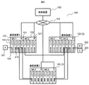
図1は、本発明の実施形態におけるネットワーク設定システムの構成例を示すブロック図である。   FIG. 1 is a block diagram illustrating a configuration example of a network setting system according to an embodiment of the present invention.

本実施形態のプログラマブルネットワークは、制御装置100及び1台以上の通信装置120を備え、コンフィギュレーションネットワーク110を介して互いに接続される。管理装置120及び通信装置120の台数は、本実施形態の台数に限定されない。   The programmable network of this embodiment includes a control device 100 and one or more communication devices 120, and is connected to each other via a configuration network 110. The number of management devices 120 and communication devices 120 is not limited to the number of the present embodiment.

制御装置100は、ネットワーク設定キュー101、ネットワーク構成DB102、ネットワーク設定手順生成部103、ネットワーク設定実行キュー104、ネットワーク設定実行部105、設定済みネットワークモデル管理部106、制御IF107、設定済みネットワークモデル108から構成される。また、制御装置100には情報を出力する出力装置と、情報を入力する入力装置を有する。これらは、本実施形態では制御IF107に含まれるものとする。   The control device 100 includes a network setting queue 101, a network configuration DB 102, a network setting procedure generation unit 103, a network setting execution queue 104, a network setting execution unit 105, a set network model management unit 106, a control IF 107, and a set network model 108. Composed. The control device 100 has an output device that outputs information and an input device that inputs information. These are assumed to be included in the control IF 107 in this embodiment.

制御装置100は、汎用のPCサーバなどを利用して実現できる。その場合、ネットワーク設定キュー101、ネットワーク構成DB102、ネットワーク設定実行キュー104、設定済みネットワークモデル108は、半導体メモリDRAM(Dynamic Random Access Memory),SRAM(Static Random Access Memory)などに格納される。ネットワーク設定手順生成部103、ネットワーク設定実行部105、設定済みネットワークモデル管理部106はCPU(Central Processing Unit)などの演算器によって実行されるプログラムとして実現される。また、FPGA(Field Programmable Gate Array)、ASIC(Application Specific Integrated Circuit)などのハードウェア回路として実現することもできる。   The control device 100 can be realized using a general-purpose PC server or the like. In this case, the network setting queue 101, the network configuration DB 102, the network setting execution queue 104, and the set network model 108 are stored in a semiconductor memory DRAM (Dynamic Random Access Memory), SRAM (Static Random Access Memory), or the like. The network setting procedure generation unit 103, the network setting execution unit 105, and the set network model management unit 106 are realized as programs executed by an arithmetic unit such as a CPU (Central Processing Unit). Moreover, it is also realizable as hardware circuits, such as FPGA (Field Programmable Gate Array) and ASIC (Application Specific Integrated Circuit).

ネットワーク設定キュー101には、オペレータによって作成されたネットワーク設定データが格納される。ネットワーク設定データの詳細については図3、図4で後述する。   The network setting queue 101 stores network setting data created by the operator. Details of the network setting data will be described later with reference to FIGS.

ネットワーク構成DB102には、オペレータによって作成されたネットワーク構成データが格納される。ネットワーク構成データの詳細については図5で例を説明する。   The network configuration DB 102 stores network configuration data created by the operator. Details of the network configuration data will be described with reference to FIG.

ネットワーク設定手順生成部103は、ネットワーク設定キュー101から読み出したネットワーク設定データ、ネットワーク構成DB102から読み出したネットワーク構成データ、設定済みネットワークモデル108をもとに、ネットワーク設定グラフを生成する。ネットワーク設定グラフとは、ネットワーク設定データの設定手順である。設定手順生成ステップ及びネットワーク設定グラフについては後述する。   The network setting procedure generation unit 103 generates a network setting graph based on the network setting data read from the network setting queue 101, the network configuration data read from the network configuration DB 102, and the set network model 108. The network setting graph is a procedure for setting network setting data. The setting procedure generation step and the network setting graph will be described later.

ネットワーク設定実行キュー104には、ネットワーク設定手順生成部により生成されたネットワーク設定グラフとネットワーク設定データが格納される。   The network setting execution queue 104 stores the network setting graph and network setting data generated by the network setting procedure generation unit.

ネットワーク設定実行部105は、ネットワーク設定データに記載された設定開始時刻になると、ネットワーク設定実行キューから、ネットワーク設定グラフとネットワーク設定データを読み出す。ネットワーク設定実行部105は、ネットワーク設定グラフをもとにネットワーク設定データを制御IF107経由で通信装置120に設定するとともに、設定済みネットワーク管理部106に同じネットワーク設定データを通知する。ネットワーク設定実行部の詳細は後述する。   The network setting execution unit 105 reads the network setting graph and the network setting data from the network setting execution queue at the setting start time described in the network setting data. The network setting execution unit 105 sets the network setting data in the communication apparatus 120 via the control IF 107 based on the network setting graph, and notifies the set network management unit 106 of the same network setting data. Details of the network setting execution unit will be described later.

設定済みネットワークモデル管理部106は、設定済みネットワークモデル108を作成・管理する。設定済みネットワークモデル管理部106は、ネットワーク設定実行部105からネットワーク設定データの通知を受けると、設定済みネットワークモデル108に設定を反映させる。設定済みネットワークモデル108は、ネットワーク構成データをもとにネットワークに存在する通信装置120をモデル化し、ネットワーク設定データから読み出した実通信装置120に設定済みの設定内容を、モデル内に保存したデータセットである。   The set network model management unit 106 creates and manages the set network model 108. Upon receiving notification of network setting data from the network setting execution unit 105, the set network model management unit 106 reflects the setting in the set network model 108. The set network model 108 is a data set in which the communication device 120 existing in the network is modeled based on the network configuration data, and the setting contents set in the actual communication device 120 read from the network setting data are stored in the model. It is.

制御IF107は、制御装置100をコンフィギュレーションネットワーク110と接続する。制御IF107は、Ethernet(登録商標)やInfiniband(登録商標)など、制御装置と通信装置が相互に通信できればよい。制御IF107は、コンフィギュレーションネットワーク110と接続できれば良く、その数は問わない。ただし、制御IF107の数を増やすことで、ネットワーク帯域のボトルネックの問題を改善できる。   The control IF 107 connects the control device 100 to the configuration network 110. The control IF 107 only needs to allow the control device and the communication device to communicate with each other, such as Ethernet (registered trademark) or Infiniband (registered trademark). The control IF 107 may be connected to the configuration network 110, and the number thereof is not limited. However, by increasing the number of control IFs 107, the problem of network bandwidth bottlenecks can be improved.

設定済みネットワークモデル108は、現在運用中であるすべての通信装置120の設定情報、及び、通信装置間の接続関係を保持する。設定済みネットワークモデル108の詳細は後述する。   The set network model 108 holds setting information of all the communication devices 120 that are currently in operation and the connection relationship between the communication devices. Details of the set network model 108 will be described later.

本実施例では、ネットワークの要求・応答回数を削減する効果がある。このため、ネットワーク遅延が大きいほど本実施例の効果も大きくなる。このため、本実施形態では、コンフィギュレーションネットワーク110の例として、高遅延のWAN(Wide Area Network)を想定したが、IEEE 802.11(登録商標)/a/b/gなどの無線LAN(Local Area Network)や、Ethernet(登録商標)などによるLANなど、他の通信手段によって置き換えられてもよい。他の通信手段の利用によって通信速度、及び配置の自由度等の改善が可能となる。   In this embodiment, there is an effect of reducing the number of network requests / responses. For this reason, the effect of the present embodiment increases as the network delay increases. For this reason, in the present embodiment, a high-delay WAN (Wide Area Network) is assumed as an example of the configuration network 110, but a wireless LAN such as IEEE 802.11 (registered trademark) / a / b / g (Local It may be replaced by other communication means such as a LAN by Area Network) or Ethernet (registered trademark). The use of other communication means can improve the communication speed and the degree of freedom of arrangement.

なお、本実施例では、ネットワーク設定手順生成部103とネットワーク設定実行部105を同じ制御装置に備えているが、それぞれ別の制御装置として構成し、LANなどのネットワーク経由で、必要なデータをやり取りしてもよい。また、ネットワーク設定キュー101、ネットワーク構成DB102、ネットワーク設定実行キュー104、設定済みネットワークモデル108等を格納する記憶装置を、制御装置外に配置することもできる。   In this embodiment, the network setting procedure generation unit 103 and the network setting execution unit 105 are provided in the same control device, but they are configured as different control devices and exchange necessary data via a network such as a LAN. May be. In addition, a storage device that stores the network setting queue 101, the network configuration DB 102, the network setting execution queue 104, the set network model 108, and the like can be arranged outside the control device.

通信装置120は、1個以上の設定IF121、1個以上の設定実行部122、1個以上のデータ転送部124、及び設定実行部122とデータ転送部124を接続する装置内ネットワーク125から構成される。通信装置120は、OpenFlow(登録商標)スイッチなどと同様に、データ転送処理を設定データで変更できる。   The communication device 120 includes one or more setting IFs 121, one or more setting execution units 122, one or more data transfer units 124, and an in-device network 125 that connects the setting execution units 122 and the data transfer units 124. The The communication device 120 can change the data transfer process with the setting data, like the OpenFlow (registered trademark) switch.

設定IF121は、通信装置120とコンフィギュレーションネットワーク110を接続する。設定IF121は、Ethernet(登録商標)やInfiniband(登録商標)など、制御装置と通信装置が相互に通信できればよい。本実施例では、通信装置120の設定を並列に実行することで、設定変更時間を短縮する効果がある。そのため、本実施形態では、通信装置120は2個以上の設定IF121を備える例を想定する。設定IF121は、一つの物理的IFを複数の論理的IFとして提供してもよい。物理的な設定IF121の数を増やすことで、ネットワーク帯域のボトルネックを改善できる効果がある。なお、ネットワーク帯域のボトルネックが問題にならないシステムでは、設定IF121は一つでもよい。   The setting IF 121 connects the communication device 120 and the configuration network 110. The setting IF 121 only needs to allow the control device and the communication device to communicate with each other, such as Ethernet (registered trademark) and Infiniband (registered trademark). In the present embodiment, the setting change time is shortened by executing the setting of the communication device 120 in parallel. Therefore, in the present embodiment, an example in which the communication apparatus 120 includes two or more setting IFs 121 is assumed. The setting IF 121 may provide one physical IF as a plurality of logical IFs. By increasing the number of physical setting IFs 121, there is an effect that the bottleneck of the network bandwidth can be improved. In a system where the bottleneck of the network bandwidth does not become a problem, the number of setting IFs 121 may be one.

設定実行部122は、制御装置100からの設定要求を受け、データ転送部124に設定を実行する。制御装置100からの設定要求は、設定キュー123に一度格納される。設定実行部122は、CPUなどの演算器によって実行されるプログラムとして、あるいは、FPGAなどにより実装される論理回路などとして実現される。設定キュー123は、半導体メモリDRAM,SRAMなどの利用が考えられる。設定の実行ステップについては後述する。   The setting execution unit 122 receives a setting request from the control device 100 and executes setting in the data transfer unit 124. A setting request from the control device 100 is stored once in the setting queue 123. The setting execution unit 122 is realized as a program executed by an arithmetic unit such as a CPU, or as a logic circuit implemented by an FPGA or the like. The setting queue 123 may be a semiconductor memory DRAM, SRAM, or the like. The setting execution step will be described later.

データ転送部124は、設定記憶部126に格納される設定データに基づいて通信装置120のデータ転送を行う。データ転送部124は、CPUなどの演算器によって実行されるプログラムとして、あるいは、FPGA、ASICなどのハードウェア回路として実現される。   The data transfer unit 124 performs data transfer of the communication device 120 based on the setting data stored in the setting storage unit 126. The data transfer unit 124 is realized as a program executed by a computing unit such as a CPU, or as a hardware circuit such as an FPGA or an ASIC.

装置内ネットワーク125は、設定実行部122とデータ転送部124間を接続する。本実施形態の装置内ネットワーク125は、電気バックプレーンを用いたLANを想定するが、その他、光バックプレーンや無線など、本実施形態に限定されない。   The in-device network 125 connects the setting execution unit 122 and the data transfer unit 124. The intra-device network 125 of this embodiment is assumed to be a LAN using an electrical backplane, but is not limited to this embodiment, such as an optical backplane or wireless.

設定記憶部126は、半導体メモリDRAM,SRAM、TCAM(Ternary Content Addressable Memory)などの利用が考えられる。本実施形態では、設定記憶部126は、OpenFlow(登録商標)のフローテーブルと同様に、2つ以上の設定記憶領域を備えることを想定する。   The setting storage unit 126 may be a semiconductor memory DRAM, SRAM, TCAM (Ternary Content Addressable Memory), or the like. In the present embodiment, it is assumed that the setting storage unit 126 includes two or more setting storage areas as in the OpenFlow (registered trademark) flow table.

図2は、実施例1のネットワーク設定システムを適用して構成したネットワークの例である。ネットワーク200は、ノードA201、ノードB202、ノードC203、制御装置100、コンフィギュレーションネットワーク110、通信装置X120(1)〜通信装置Z120(3)から構成される。ノードA201、ノードB202、ノードC203は、端末や制御装置100が管理していない通信装置を想定している。   FIG. 2 is an example of a network configured by applying the network setting system according to the first embodiment. The network 200 includes a node A 201, a node B 202, a node C 203, a control device 100, a configuration network 110, and communication devices X120 (1) to Z120 (3). The node A 201, the node B 202, and the node C 203 are assumed to be communication devices that are not managed by the terminal or the control device 100.

本実施形態では、制御装置100と通信装置120間のプロトコルとしてOpenFlow(登録商標)を利用すること想定している。   In this embodiment, it is assumed that OpenFlow (registered trademark) is used as a protocol between the control device 100 and the communication device 120.

通信装置X120(1)〜通信装置Z(3)は、それぞれ、設定実行部122であるMC(Management Card)2枚、データ転送部124であるLC(Line Card)8枚を備える。LCは、データ転送用ポート210を4ポート備え、MCは設定IF121を備える。   Each of the communication devices X120 (1) to Z (3) includes two MC (Management Card) that is the setting execution unit 122 and eight LC (Line Card) that is the data transfer unit 124. The LC includes four data transfer ports 210, and the MC includes a setting IF 121.

以降、LCn(nは自然数)のm(mは自然数)番目のポートを、Port m/n
と表現する。本実施形態では、ノードAが通信装置X120(1)のPort 1/1と、通信装置X120(1)のPort 1/2が通信装置Z120(3)のPort 1/1と、通信装置X120(1)のPort 2/2が通信装置Z120(3)のPort 2/1と、通信装置X120(1)のPort 5/1と通信装置Y120(2)のPort 5/1と、通信装置Z120(3)のPort 1/8と通信装置Y120(2)のPort 1/7と、通信装置Z120(3)のPort 2/8と通信装置Y120(2)のPort 2/7と、ノードBが通信装置120Y(2)のPort 1/8と、ノードCが通信装置Y120(2)のPort 2/8とが、それぞれ接続されている。
Hereinafter, the m-th port of LCn (n is a natural number) (m is a natural number) is referred to as Port m / n.
It expresses. In this embodiment, the node A is Port 1/1 of the communication device X120 (1), the Port 1/2 of the communication device X120 (1) is the Port 1/1 of the communication device Z120 (3), and the communication device X120 ( 1) Port 2/2 is communication device Z120 (3) Port 2/1, communication device X120 (1) Port 5/1, communication device Y120 (2) Port 5/1, and communication device Z120 ( 3) Port 1/8, communication device Y120 (2), Port 1/7, communication device Z120 (3), Port 2/8, communication device Y120 (2), Port 2/7, and node B communicate with each other. Port 1/8 of the device 120Y (2) and Port 2/8 of the communication device Y120 (2) are connected to the node C, respectively.

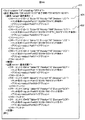
図3は、図1のネットワーク設定キュー101に格納される、オペレータによって作成されたネットワーク設定データの例である。本実施形態では、ネットワーク設定データ300をXML(eXtensible Markup Language)形式で記述しているが、等価のデータを含んでいればXML形式以外の形式で記述されてもよい。   FIG. 3 is an example of network setting data created by an operator stored in the network setting queue 101 of FIG. In this embodiment, the network setting data 300 is described in the XML (eXtensible Markup Language) format, but may be described in a format other than the XML format as long as equivalent data is included.

ネットワーク設定データ300は、追加もしくは削除するネットワーク全体の設定を定義する。   The network setting data 300 defines settings for the entire network to be added or deleted.

行301の設定タグは、ネットワーク設定データが記載されたファイルであることを示しており、設定の有効期限が開始日時プロパティと終了日時プロパティで指定される。   The setting tag in the row 301 indicates that the file contains network setting data, and the expiration date of the setting is specified by the start date / time property and the end date / time property.

行302の装置タグは、設定対象の通信装置120をnameプロパティで特定する。   The device tag in the row 302 identifies the communication device 120 to be set by the name property.

行303のフローエントリタグは、対象となる通信装置120の設定記憶部126に格納する設定内容を指定する。行303のIDプロパティには、フローエントリを特定するユニークな値を指定する。Tableプロパティには複数ある設定記憶部(テーブル)126を特定する値を指定する。Priorityタグはフローエントリ間の優先度を指定する。Devicesプロパティは、データ転送部124であるLCを特定する値を指定する。これらにより、設定データに含まれる設定(例えばフローエントリ)の、通信装置内の保存先(例えばフローテーブル)が指定される。典型的な例では、設定には、処理されるフレームの条件(マッチング条件)と、条件にあてはまるフレームの処理内容が含まれる。   The flow entry tag in the row 303 designates setting contents to be stored in the setting storage unit 126 of the target communication device 120. In the ID property of the row 303, a unique value specifying the flow entry is designated. In the Table property, a value specifying a plurality of setting storage units (tables) 126 is designated. The Priority tag specifies the priority between flow entries. The Devices property specifies a value that identifies the LC that is the data transfer unit 124. Thus, a storage destination (for example, a flow table) in the communication device for a setting (for example, a flow entry) included in the setting data is designated. In a typical example, the setting includes a condition of a frame to be processed (matching condition) and processing contents of a frame that satisfies the condition.

行304のマッチ条件タグは、データ転送処理対象のフレームの条件を指定する。行304の例では、入力ポートがPort 1/1かつVLANが100のフレームが対象となる。   The match condition tag in the row 304 specifies the condition of the frame subject to data transfer processing. In the example of the row 304, a frame in which the input port is Port 1/1 and the VLAN is 100 is targeted.

行305のアクションタグは、マッチング条件に該当したフレームの処理内容を指定する。行305の例では、出力先Normalが指定されており、OpenFlow(登録商標)の規定では、通信装置の実装依存の動作となる。本実施形態では、出力先がNormalの場合、L2スイッチと同じ、FDB(Forwarding DataBase)に基づく転送動作を想定する。   The action tag in line 305 designates the processing content of the frame corresponding to the matching condition. In the example of the row 305, the output destination Normal is specified, and the operation of the communication apparatus depends on the implementation of OpenFlow (registered trademark). In this embodiment, when the output destination is Normal, the same transfer operation based on FDB (Forwarding DataBase) as the L2 switch is assumed.

行306は、ノードA201のフローエントリを示している。ノードAは、端末や制御装置100が管理していない通信装置のため、行306のTypeプロパティにDummyを指定し、行307で出力先がPort 1/1となる仮のフローエントリを指定している。以降、既出のタグについては説明を省略する。   A row 306 indicates a flow entry of the node A 201. Since node A is a communication device that is not managed by the terminal or the control device 100, Dummy is specified for the Type property in line 306, and a temporary flow entry whose output destination is Port 1/1 is specified in line 307. Yes. Hereinafter, description of the already described tags is omitted.

図4A,図4Bは、同じくネットワーク設定キュー101に格納されるネットワーク設定データの例である。ネットワーク設定データ400は、フローエントリタグ401、402を含む。   4A and 4B are examples of network setting data stored in the network setting queue 101 in the same manner. The network setting data 400 includes flow entry tags 401 and 402.

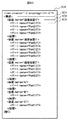
図5A,図5Bは、図1のネットワーク構成DB102に格納されるネットワーク構成データの例である。ネットワーク設定データと同様にXML形式で記述しているが、等価のデータを含んでいればXML形式以外の形式で記述されてもよい。   5A and 5B are examples of network configuration data stored in the network configuration DB 102 of FIG. Although it is described in the XML format similarly to the network setting data, it may be described in a format other than the XML format as long as equivalent data is included.

ネットワーク構成データ500は、ネットワークの物理的な構成情報を定義する。   The network configuration data 500 defines physical configuration information of the network.

行501の構成タグは、ネットワーク構成データが記載されたファイルであることを示している。   The configuration tag in the row 501 indicates that the file describes network configuration data.

行502の装置タグは、ネットワークに存在する装置をnameプロパティで指定する。   The device tag in the row 502 specifies a device existing in the network by the name property.

行503のポートタグは、装置が備えるポートをnameプロパティで指定する。   The port tag in the row 503 designates a port included in the device by the name property.

行504の接続タグは、装置間の接続関係を指定する。   The connection tag in the row 504 specifies a connection relationship between devices.

行505のFromタグは接続元、行506のToタグは接続先を表す。   The From tag in line 505 represents the connection source, and the To tag in line 506 represents the connection destination.

続いて、本実施形態におけるプログラマブルネットワークの動作の概略について説明する。まず、ネットワーク200(図2参照)にネットワーク設定データ400(図4参照)を追加する動作を例として、ネットワーク構築のステップを説明する。   Next, an outline of the operation of the programmable network in this embodiment will be described. First, the steps of network construction will be described by taking as an example the operation of adding the network setting data 400 (see FIG. 4) to the network 200 (see FIG. 2).

図6は、本実施形態におけるネットワーク構築を説明するフローチャート600である。図1のネットワーク設定手順生成部103で実行される。   FIG. 6 is a flowchart 600 for explaining network construction in the present embodiment. It is executed by the network setting procedure generation unit 103 in FIG.

ネットワーク構築は、開始状態601から始まり、ステップ602に進む。   The network construction starts from the start state 601 and proceeds to step 602.

ステップ602では、まず、オペレータが物理的なネットワーク構成からネットワーク構成データ500(図5参照)を作成し、ネットワーク構成DB102に格納する。次に、オペレータがネットワーク構成をもとにユーザの要求仕様を満たす論理的なネットワーク設定であるネットワーク設定データ400(図4参照)を作成し、ネットワーク設定キュー101に格納する。ネットワーク設定データがネットワーク設定キュー101に格納されるとステップ603に進む。   In step 602, first, the operator creates network configuration data 500 (see FIG. 5) from the physical network configuration and stores it in the network configuration DB. Next, the operator creates network setting data 400 (see FIG. 4) that is a logical network setting that satisfies the user's required specifications based on the network configuration, and stores it in the network setting queue 101. When the network setting data is stored in the network setting queue 101, the process proceeds to step 603.

ステップ603では、制御装置100のネットワーク設定手順生成部103が装置単位の設定手順を決定し、ステップ604に進む。   In step 603, the network setting procedure generation unit 103 of the control device 100 determines a setting procedure for each device, and the process proceeds to step 604.

ステップ604では、ネットワーク設定手順生成部103がネットワーク設定データ、ネットワーク構成データをもとに装置内の設定手順を作成し、ステップ605に進む。   In step 604, the network setting procedure generation unit 103 creates a setting procedure in the apparatus based on the network setting data and the network configuration data, and the process proceeds to step 605.

ステップ605では、設定済みネットワークモデルをもとに、ネットワーク200に設定済みのネットワーク設定と、ステップ604までで作成された設定手順が競合しないように設定手順を作成し、ステップ606に進む。   In step 605, a setting procedure is created so that the network setting already set in the network 200 does not conflict with the setting procedure created up to step 604 based on the set network model, and the process proceeds to step 606.

ステップ606は、装置内の設定先に依存して(基づいて)定められる設定手順の決定処理である。ステップ606では、ネットワーク設定データ400に記載された設定記憶部126の情報をもとに、異なる設定記憶部126に同時に設定できる設定手順を作成し、ステップ607に進む。   Step 606 is a setting procedure determination process determined depending on (based on) the setting destination in the apparatus. In step 606, based on the information in the setting storage unit 126 described in the network setting data 400, a setting procedure that can be set simultaneously in different setting storage units 126 is created, and the process proceeds to step 607.

ステップ607では、ステップ606までで作成された設定手順に通信装置120ごとにシーケンス番号を付与し、ステップ608に進む。   In step 607, a sequence number is assigned to each communication device 120 in the setting procedure created up to step 606, and the process proceeds to step 608.

ステップ608では、制御装置100が設定処理を開始し、ステップ609に進む。   In step 608, the control device 100 starts the setting process and proceeds to step 609.

ステップ609では通信装置120が設定処理を実行し、ステップ610に進み、終了する。   In step 609, the communication apparatus 120 executes setting processing, proceeds to step 610, and ends.

以上説明したように、本実施例の制御装置は、入力装置、出力装置、記憶装置102,108、および処理装置を備え、少なくとも一つの通信装置120とネットワーク110を介して接続される。制御装置は入力装置から入力され、あるいは記憶装置に記憶されたネットワーク設定データ300に基づいて、通信装置にネットワーク設定を行う。処理装置は、ネットワーク設定の設定手順を生成するネットワーク設定手順生成部103を有し、ネットワーク設定手順生成部103は、入力装置から入力され、あるいは記憶装置に記憶されているネットワーク構成データ500から通信装置の接続関係を検出する機能を有する。処理装置は、検出した接続関係と、ネットワーク設定データに基づき、通信装置単位の設定順序を生成する機能を有し、通信装置単位の設定順序に基づいて新規ネットワーク設定の設定手順を生成する。本実施例では、ネットワークの設定手順は、既存のネットワーク構成とネットワーク設定データに基づいて、動的に生成される。これにより、既存のネットワーク構成に影響を与えない設定順序を生成することができる。   As described above, the control device of this embodiment includes the input device, the output device, the storage devices 102 and 108, and the processing device, and is connected to at least one communication device 120 via the network 110. The control device performs network setting for the communication device based on the network setting data 300 input from the input device or stored in the storage device. The processing apparatus includes a network setting procedure generation unit 103 that generates a setting procedure for network settings. The network setting procedure generation unit 103 communicates from network configuration data 500 that is input from an input device or stored in a storage device. It has a function of detecting the connection relation of devices. The processing device has a function of generating a setting order for each communication device based on the detected connection relationship and the network setting data, and generates a setting procedure for new network setting based on the setting order for each communication device. In this embodiment, the network setting procedure is dynamically generated based on the existing network configuration and network setting data. As a result, a setting order that does not affect the existing network configuration can be generated.

以降、フローチャート600の各ステップの詳細な説明をする。   Hereinafter, each step of the flowchart 600 will be described in detail.

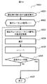
図7は、図6の装置単位の設定手順決定ステップ603の詳細を説明するフローチャート700である。まず、開始状態701から始まり、ステップ702に進む。   FIG. 7 is a flowchart 700 illustrating details of the setting procedure determination step 603 for each apparatus in FIG. First, starting from the start state 701, the process proceeds to step 702.

ステップ702では、ネットワーク設定手順生成部103がネットワーク設定キュー101からネットワーク設定データ400を読み出し、ステップ703に進む。   In step 702, the network setting procedure generation unit 103 reads the network setting data 400 from the network setting queue 101, and proceeds to step 703.

ステップ703では、ネットワーク設定手順生成部103がネットワーク構成DB102からネットワーク構成データ500を読み出し、ステップ704に進む。   In step 703, the network setting procedure generation unit 103 reads the network configuration data 500 from the network configuration DB 102 and proceeds to step 704.

ステップ704では、ネットワーク設定手順生成部103が、ネットワーク設定データ400をもとに装置をグラフノードとする装置設定隣接リストを初期化し、ステップ705に進む。   In step 704, the network setting procedure generation unit 103 initializes a device setting neighbor list in which the device is a graph node based on the network setting data 400, and the process proceeds to step 705.

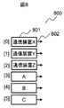
図8は、図7の装置設定隣接リスト初期化ステップ704で初期化された、装置設定隣接リスト800である。図8に示すグラフノード801を識別する「通信装置X」「通信装置Y」「通信装置Z」等は、図4のネットワーク設定データ400で記述された「装置name」である。すなわち、装置設定隣接リスト800は、ネットワーク設定データ400の装置タグに定義された装置をグラフノード801、装置間の接続状態をエッジ802としたグラフである。初期化されたグラフは接続状態がないグラフとなる。   FIG. 8 is a device setting neighbor list 800 initialized in the device setting neighbor list initialization step 704 of FIG. The “communication device X”, “communication device Y”, “communication device Z”, and the like that identify the graph node 801 illustrated in FIG. 8 are “device names” described in the network setting data 400 of FIG. That is, the device setting neighbor list 800 is a graph in which the device defined in the device tag of the network setting data 400 is a graph node 801 and the connection state between devices is an edge 802. The initialized graph is a graph with no connection state.

フローチャート700に戻り、ステップ705からステップ711は、図8の装置設定隣接リスト800のグラフノード801に対する繰り返し処理である。すなわちここでは、変数Uは図8の[0][1][2][3][4][5]であって、各グラフノード(装置)に対して繰り返される。   Returning to the flowchart 700, steps 705 to 711 are repetitive processing for the graph node 801 in the apparatus setting adjacent list 800 of FIG. That is, here, the variable U is [0] [1] [2] [3] [4] [5] in FIG. 8 and is repeated for each graph node (device).

ステップ706からステップ710は、変数Uのグラフノードに対応する、ネットワーク設定データ400から取得したフローエントリに対する繰り返し処理である。例えば、図8でUが[0]のグラフノード(通信装置X)に対応するフローエントリは、ネットワーク設定データ400から”a”,”b”,”c”,”d”とわかる。よって、変数Eは図11の[0][1][2][3]であって、各フローエントリに対して繰り返される。   Steps 706 to 710 are an iterative process for the flow entry acquired from the network setting data 400 corresponding to the graph node of the variable U. For example, the flow entry corresponding to the graph node (communication device X) whose U is [0] in FIG. 8 is known as “a”, “b”, “c”, “d” from the network setting data 400. Therefore, the variable E is [0] [1] [2] [3] in FIG. 11 and is repeated for each flow entry.

ステップ707では、ネットワーク設定手順生成部103が、ネットワーク構成データ500から取得した変数Uのグラフノードに対応するポート情報と、変数Eのフローエントリのマッチ条件に記載された入力ポートであるinportの値(変数Pに格納)を照合し、ステップ708に進む。すなわちステップ707では、ネットワークを構成するグラフノード(装置)のポートのうち、ネットワーク構成データ500が入力ポートとして指定しているポートを抽出している。   In step 707, the network setting procedure generation unit 103 receives the port information corresponding to the graph node of the variable U acquired from the network configuration data 500 and the value of the inport that is the input port described in the match condition of the flow entry of the variable E. (Stored in variable P) is collated, and the process proceeds to step 708. That is, in step 707, the ports specified by the network configuration data 500 as input ports are extracted from the ports of the graph nodes (apparatuses) constituting the network.

ステップ708では、ネットワーク設定手順生成部103が、変数Pのポートが接続されている装置(変数Vに格納)を、ネットワーク構成データ500の接続タグのエントリから検索し、ステップ709に進む。これにより、ネットワーク構成データ500が入力ポートとして指定しているポートに接続される他の装置Vが抽出される。   In step 708, the network setting procedure generation unit 103 searches for the device to which the port of the variable P is connected (stored in the variable V) from the connection tag entry of the network configuration data 500, and proceeds to step 709. As a result, another device V connected to the port designated as the input port by the network configuration data 500 is extracted.

ステップ709では、ネットワーク設定手順生成部103が、送信元を後に設定するという、設定手順決定ポリシー713に基づいて、装置設定隣接リスト800の変数Uの接続先として、変数Vを追加し、ステップ710に進む。   In step 709, the network setting procedure generation unit 103 adds a variable V as a connection destination of the variable U in the device setting adjacent list 800 based on the setting procedure determination policy 713 that the transmission source is set later. Proceed to

ステップ710では、繰り返し処理が終わっていればステップ711に進み、終わっていなければステップ706に戻る。   In step 710, if the repetitive processing is completed, the process proceeds to step 711. If not completed, the process returns to step 706.

ステップ711では、繰り返し処理が終わっていればステップ712に進み、終わっていなければステップ705に戻る。ステップ712は終了状態である。   In step 711, if the repetitive processing is completed, the process proceeds to step 712. If not completed, the process returns to step 705. Step 712 is an end state.

図9は、図7の装置単位の設定手順決定ステップ700が終了した状態の、装置設定隣接リスト900である。エッジ901の右側に書かれているグラフノードは、エッジ901の左側のグラフノードの接続元のグラフノード一覧を表している。   FIG. 9 is a device setting adjacency list 900 in a state where the device unit setting procedure determining step 700 of FIG. 7 has been completed. The graph node written on the right side of the edge 901 represents a graph node list of connection sources of the graph node on the left side of the edge 901.

装置単位の設定手順は、装置設定隣接リスト900に基づいて実行される。例えば、通信装置Xを開始位置とした場合、次は通信装置Yもしくは通信装置ZもしくはAとなる。   The setting procedure for each device is executed based on the device setting adjacent list 900. For example, when the communication device X is the start position, the communication device Y or the communication device Z or A is next.

このように、装置単位の設定手順決定ステップ700により、ネットワーク設定データ400とネットワーク構成データ500から、ネットワーク下流から設定する手順が生成される。ネットワーク下流から設定することで、予期しないパケットの流入を防ぐことができ、設定途中に起き得るネットワーク障害の回避が図れる。ここで、データの送信側を上流と称し、受信側を下流と称している。さらに好ましくは、装置設定隣接リスト900において、接続関係のない装置間を認識することで、安全に複数の装置を並列に設定できるため、設定実行時間の短縮が図れる。   In this way, a procedure for setting from the downstream side of the network is generated from the network setting data 400 and the network configuration data 500 by the device-based setting procedure determining step 700. By setting from the downstream side of the network, unexpected packet inflow can be prevented, and network failure that may occur during the setting can be avoided. Here, the data transmission side is referred to as upstream, and the reception side is referred to as downstream. More preferably, by recognizing between devices having no connection relationship in the device setting adjacent list 900, a plurality of devices can be safely set in parallel, so that setting execution time can be shortened.

また、自動的に装置単位の設定手順の組み合わせを図9の例では12通りに絞り込むことができ、設定手順の決定時間を短縮できる。装置単位の設定手順決定ステップ603を使用しない場合、装置数をnとした場合、設定手順の候補はnの階乗通り存在するため、ネットワーク設定データ400では720通りの候補から選択する必要がある。   In addition, the number of combinations of setting procedures for each device can be automatically narrowed down to twelve in the example of FIG. 9, and the setting procedure determination time can be shortened. When the setting procedure determination step 603 for each device is not used and when the number of devices is n, there are n setting procedure candidates, and the network setting data 400 needs to be selected from 720 candidates. .

図10は、図6の装置内の設定手順決定ステップ604の詳細を説明するフローチャート1000である。まず、開始状態1001から始まり、ステップ1002に進む。   FIG. 10 is a flowchart 1000 illustrating details of the setting procedure determination step 604 in the apparatus of FIG. First, starting from the start state 1001, the process proceeds to step 1002.

ステップ1002からステップ1013までは、装置設定隣接リスト900のグラフノード801(変数Uに格納)の繰り返しである。   Steps 1002 to 1013 are repetitions of the graph node 801 (stored in the variable U) of the device setting adjacent list 900.

ステップ1003では、ネットワーク設定手順生成部103が、ネットワーク設定データ400をもとに変数Uの装置のフローエントリをグラフノードとするフローエントリ隣接リストを初期化し、ステップ1004に進む。   In step 1003, the network setting procedure generation unit 103 initializes a flow entry adjacent list in which the flow entry of the device of the variable U is a graph node based on the network setting data 400, and the process proceeds to step 1004.

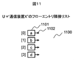
図11は、図10のフローエントリ隣接リスト初期化ステップ1003で初期化された、フローエントリ隣接リスト1100である。図中に示すグラフノード1101を識別する「a」,「b」,「c」,「d」は、図4のネットワーク設定データ400で示したフローエントリIDである。フローエントリ隣接リスト1100は、ネットワーク設定データ400のフローエントリタグに定義されたフローエントリをグラフノード1101、フローエントリの設定手順をエッジ1102で表現したグラフである。初期化されたグラフは設定の順序関係がないグラフである。   FIG. 11 is a flow entry adjacency list 1100 initialized in the flow entry adjacency list initialization step 1003 of FIG. “A”, “b”, “c”, and “d” for identifying the graph node 1101 shown in the figure are the flow entry IDs indicated by the network setting data 400 in FIG. The flow entry adjacency list 1100 is a graph in which a flow entry defined in the flow entry tag of the network setting data 400 is represented by a graph node 1101 and a flow entry setting procedure is represented by an edge 1102. The initialized graph has no setting order relationship.

図10のフローチャート1000に戻り、ステップ1004からステップ1012までは、変数Uの装置のフローエントリに対する(変数Eに格納)繰り返しである。ステップ1005からステップ1011までは、変数Eを除く、変数Uの装置のフローエントリに対する繰り返しである。変数Eを除くのは、同一の装置相互の関係は考慮しなくてよいからである。   Returning to the flowchart 1000 of FIG. 10, steps 1004 to 1012 are repetitions for the flow entry of the apparatus of the variable U (stored in the variable E). Steps 1005 to 1011 are repeated for the flow entry of the apparatus of the variable U, excluding the variable E. The variable E is excluded because it is not necessary to consider the relationship between the same devices.

ステップ1006では、ネットワーク設定手順生成部103が、変数EのフローエントリのTableプロパティと、変数FのフローエントリのTableプロパティが一致しているか確認し、Yesの場合はステップ1007に、Noの場合はステップ1008に進む。Tableプロパティが一致している場合は、フローエントリの設定相互の干渉を考慮する必要があるからである。   In Step 1006, the network setting procedure generation unit 103 checks whether the Table property of the flow entry of the variable E matches the Table property of the flow entry of the variable F. If Yes, the network property is generated in Step 1007. Proceed to step 1008. This is because when the Table properties match, it is necessary to consider mutual interference between the flow entry settings.

ステップ1007では、ネットワーク設定手順生成部103が、後述するフローチャート1200を実行し、Tableプロパティが同じ場合に、変数Fのフローエントリを、変数Eのフローエントリの後に実行するか決定し、ステップ1009に進む。   In step 1007, the network setting procedure generation unit 103 executes a flowchart 1200 described later. When the table property is the same, the network setting procedure generation unit 103 determines whether to execute the variable F flow entry after the variable E flow entry. move on.

ステップ1008では、ネットワーク設定手順生成部103が、後述するフローチャート1400を実行し、Tableプロパティが異なる場合に、変数Fのフローエントリを、変数Eのフローエントリの後に実行するか決定し、ステップ1009に進む。   In step 1008, the network setting procedure generation unit 103 executes a flowchart 1400 to be described later. When the table property is different, the network setting procedure generation unit 103 determines whether to execute the flow entry of the variable F after the flow entry of the variable E. move on.

ステップ1009では、ネットワーク設定手順生成部103がステップ1007またはステップ1008の結果を確認し、Yesの場合はステップ1010に、Noの場合はステップ1011に進む。   In step 1009, the network setting procedure generation unit 103 confirms the result of step 1007 or step 1008. If yes, the process proceeds to step 1010. If no, the process proceeds to step 1011.

ステップ1010では、ネットワーク設定手順生成部103が、フローエントリ隣接リストに変数Fのフローエントリを変数Eのフローエントリの後手順として登録し、ステップ1011に進む。   In step 1010, the network setting procedure generation unit 103 registers the flow entry of the variable F in the flow entry adjacent list as a post procedure of the flow entry of the variable E, and proceeds to step 1011.

ステップ1011では、繰り返し処理が終わっていればステップ1012に進み、終わっていなければステップ1005に戻る。   In step 1011, if the repetitive processing is completed, the process proceeds to step 1012. If not completed, the process returns to step 1005.

ステップ1012では、繰り返し処理が終わっていればステップ1013に進み、終わっていなければステップ1004に戻る。   In step 1012, if the repetition processing is finished, the process proceeds to step 1013, and if not, the process returns to step 1004.

ステップ1013では、繰り返し処理が終わっていればステップ1014に進み、終わっていなければステップ1002に戻る。ステップ1014は終了状態である。   In step 1013, if the repetition processing is completed, the process proceeds to step 1014. If not completed, the process returns to step 1002. Step 1014 is an end state.

図12は、図10の決定ステップ1008で、Tableプロパティが異なる場合に、変数Eのフローエントリを、変数Fのフローエントリより先に実行すべきか判断するフローチャート1200である。まず、開始状態1201から始まり、ステップ1202に進む。   FIG. 12 is a flowchart 1200 for determining whether the flow entry of the variable E should be executed before the flow entry of the variable F when the Table property is different in the determination step 1008 of FIG. First, starting from the start state 1201, the process proceeds to step 1202.

ステップ1202では、ネットワーク設定手順生成部103が、フローエントリを追加するか削除するか判断し、Yesの場合はステップ1203に、Noの場合は、ステップ1205に進む。フローエントリを追加するか削除するかの判断は、オペレータが指定する方法や、ネットワーク設定データ400の有効期限をもとに、ネットワーク設定手順生成部103が、終了時刻前であれば追加、終了時刻後であれば削除すると判断する方法などが考えられる。   In Step 1202, the network setting procedure generation unit 103 determines whether to add or delete a flow entry. If Yes, the process proceeds to Step 1203. If No, the process proceeds to Step 1205. Whether the flow entry is added or deleted is determined based on the method specified by the operator or the expiration date of the network setting data 400. If the network setting procedure generation unit 103 is before the end time, the addition or end time is determined. A method of determining to delete it later can be considered.

ステップ1203では、ネットワーク設定手順生成部103が、変数E、変数Fのフローエントリのアクション優先度をそれぞれ、後述するネットワーク設定手順生成部103が備えるアクション優先度テーブル1300から検索し、ステップ1204に進む。   In step 1203, the network setting procedure generation unit 103 searches the action priority of the flow entry of the variable E and variable F from the action priority table 1300 provided in the network setting procedure generation unit 103 described later, and proceeds to step 1204. .

図13は、フローエントリのアクション優先度テーブルである。このテーブルは図12の検索ステップ1203、1205で用いる。アクション優先度テーブルは、フローエントリに含まれるアクションの実行優先度が記載されている。優先度は、OpenFlow(登録商標)に規定された値を固定値としてネットワーク設定手順生成部103に格納する方法や、オペレータが任意の値を設定する方法などが考えられる。   FIG. 13 is a flow entry action priority table. This table is used in search steps 1203 and 1205 in FIG. The action priority table describes the execution priority of actions included in the flow entry. As the priority, a method of storing a value defined in OpenFlow (registered trademark) in the network setting procedure generation unit 103 as a fixed value, a method of setting an arbitrary value by an operator, or the like can be considered.

図12のフローチャート1200に戻って、ステップ1204では、ネットワーク設定手順生成部103が、変数Eのアクション優先度が、変数Fのアクション優先度より高いか確認し、Yesの場合はステップ1207に進み、Noの場合は、ステップ1210に進む。   Returning to the flowchart 1200 of FIG. 12, in Step 1204, the network setting procedure generation unit 103 checks whether the action priority of the variable E is higher than the action priority of the variable F. If Yes, the process proceeds to Step 1207. If no, the process proceeds to step 1210.

ステップ1205では、ネットワーク設定手順生成部103が、変数E、変数Fのフローエントリのアクション優先度をそれぞれ、後述するネットワーク設定手順生成部103が備えるアクション優先度テーブル1300から検索し、ステップ1206に進む。   In step 1205, the network setting procedure generation unit 103 searches the action priority of the flow entry of the variable E and variable F from the action priority table 1300 provided in the network setting procedure generation unit 103 described later, and proceeds to step 1206. .

ステップ1206では、ネットワーク設定手順生成部103が、変数Eのアクション優先度が、変数Fのアクション優先度より低いか確認し、Yesの場合はステップ1207に進み、Noの場合は、ステップ1210に進む。   In step 1206, the network setting procedure generation unit 103 checks whether the action priority of the variable E is lower than the action priority of the variable F. If Yes, the process proceeds to step 1207. If No, the process proceeds to step 1210. .

ステップ1207では、ネットワーク設定手順生成部103が後述するフローチャート1500を実行し、変数E、変数Fそれぞれのフローエントリのマッチ条件の包含関係を決定し、ステップ1208に進む。   In step 1207, the network setting procedure generation unit 103 executes a flowchart 1500 to be described later, determines the inclusion relationship of the match conditions of the flow entries of the variables E and F, and proceeds to step 1208.

ステップ1208では、ネットワーク設定手順生成部103が、ステップ1207の結果が「変数Eと変数Fは排他関係」であるかを確認し、Yesであればステップ1209に、Noであればステップ1210に進む。   In step 1208, the network setting procedure generation unit 103 checks whether the result of step 1207 is “exclusive relationship between variable E and variable F”. If yes, the process proceeds to step 1209, and if no, the process proceeds to step 1210. .

ステップ1209は呼び出し元にYesを返し、ステップ1210は呼び出し元にNoを返す。   Step 1209 returns Yes to the caller, and Step 1210 returns No to the caller.

このように、フローチャート1200において、アクション優先度に基づき設定手順を決定することで、データ転送部124がポートからパケットを出力するアクション(output)を実行する前に、残りの実行されるべきアクションすべてが実行されることを保証でき、設定途中のネットワーク障害の回避を図れる。また、強制される実行の順序がないことを検出できるため、並列化により設定実行時間の短縮化が実現できる。   As described above, in the flowchart 1200, by determining the setting procedure based on the action priority, before the data transfer unit 124 executes the action (output) of outputting the packet from the port, all the remaining actions to be executed are performed. Can be ensured to be executed, and network failure during setting can be avoided. In addition, since it is possible to detect that there is no forced execution order, it is possible to reduce the set execution time by parallelization.

図14は、図10の決定ステップ1007で、Tableプロパティが同じ場合に、変数Eのフローエントリを、変数Fのフローエントリより先に実行すべきか判断するフローチャート1400である。まず、開始状態1401から始まり、ステップ1402に進む。ステップ1402では、ネットワーク設定手順生成部103が、フローエントリを追加するか削除するか判断し、Yesの場合はステップ1403に、Noの場合は、ステップ1405に進む。フローエントリを追加するか削除するかの判断は、ステップ1202の場合と同様でよい。   FIG. 14 is a flowchart 1400 for determining whether the flow entry of the variable E should be executed before the flow entry of the variable F when the Table property is the same in the determination step 1007 of FIG. First, starting from the start state 1401, the process proceeds to step 1402. In Step 1402, the network setting procedure generation unit 103 determines whether to add or delete a flow entry. If Yes, the process proceeds to Step 1403. If No, the process proceeds to Step 1405. The determination of whether to add or delete a flow entry may be the same as in step 1202.

ステップ1403では、ネットワーク設定手順生成部103が後述するフローチャート1500を実行し、変数E、変数Fそれぞれのフローエントリのマッチ条件の包含関係を決定し、ステップ1404に進む。ステップ1404では、ネットワーク設定手順生成部103が、ステップ1403の結果が、「変数Eが変数Fに包含される関係」で、かつ、変数EのフローエントリのPriorityが変数FのフローエントリのPriorityより大きいかを確認し、Yesであればステップ1407に、Noであればステップ1408に進む。   In step 1403, the network setting procedure generation unit 103 executes a flowchart 1500 described later, determines the inclusion relationship of the match conditions of the flow entries of the variable E and variable F, and proceeds to step 1404. In step 1404, the network setting procedure generation unit 103 determines that the result of step 1403 is “Relationship in which variable E is included in variable F”, and the priority of the flow entry of variable E is the priority of the flow entry of variable F. If it is Yes, the process proceeds to Step 1407, and if No, the process proceeds to Step 1408.

ステップ1405では、ネットワーク設定手順生成部103が後述するフローチャート1500を実行し、変数E、変数Fそれぞれのフローエントリのマッチ条件の包含関係を決定し、ステップ1406に進む。ステップ1406では、ネットワーク設定手順生成部103が、ステップ1405の結果が、「変数Eが変数Fを包含する関係」で、かつ、変数EのフローエントリのPriorityが変数FのフローエントリのPriority未満かを確認し、Yesであればステップ1407に、Noであればステップ1408に進む。ステップ1407は呼び出し元にYesを返し、ステップ1408は呼び出し元にNoを返す。   In step 1405, the network setting procedure generation unit 103 executes a flowchart 1500 described later, determines the inclusion relationship of the match conditions of the flow entries of the variables E and F, and proceeds to step 1406. In step 1406, the network setting procedure generation unit 103 determines whether the result of step 1405 is “a relation in which variable E includes variable F” and the priority of the flow entry of variable E is less than the priority of the flow entry of variable F. If yes, go to step 1407; if no, go to step 1408. Step 1407 returns Yes to the caller, and Step 1408 returns No to the caller.

図15は、図12の決定ステップ1207で、マッチ条件の包含関係を決定するフローチャート1500である。マッチ条件の包含関係を決定ステップは引数として、2つのフローエントリEとフローエントリFを取る。まず、開始状態1501から始まり、ステップ1502に進む。ステップ1502では、ネットワーク設定手順生成部103が、後述する「変数Eが変数Fに等しい関係」か確認するフローチャート1600を実行し、ステップ1503に進む。ステップ1503では、ネットワーク設定手順生成部103が、ステップ1502の結果を確認し、Yesの場合はステップ1504に、Noの場合は1503に進む。   FIG. 15 is a flowchart 1500 for determining the inclusion relationship of match conditions in the determination step 1207 of FIG. The step of determining the inclusion relation of the match condition takes two flow entries E and F as arguments. First, starting from the start state 1501, the process proceeds to step 1502. In step 1502, the network setting procedure generation unit 103 executes a flowchart 1600 for confirming whether “the variable E is equal to the variable F”, which will be described later, and proceeds to step 1503. In step 1503, the network setting procedure generation unit 103 confirms the result of step 1502. If yes, the process proceeds to step 1504, and if no, the process proceeds to 1503.

ステップ1505では、ネットワーク設定手順生成部103が「変数Eと変数Fが排他関係」かを確認するステップ1700を実行し、ステップ1506に進む。ステップ1506では、ネットワーク設定手順生成部103がステップ1505の結果を確認し、Yesの場合はステップ1507に、Noの場合はステップ1508に進む。   In step 1505, the network setting procedure generation unit 103 executes step 1700 for confirming whether “variable E and variable F are in an exclusive relationship”, and proceeds to step 1506. In step 1506, the network setting procedure generation unit 103 checks the result of step 1505. If Yes, the process proceeds to step 1507. If No, the process proceeds to step 1508.

ステップ1508では、ネットワーク設定手順生成部103が「変数Eが変数Fに包含される関係」か確認するフローチャート1800を実行し、ステップ1509に進む。ステップ1509では、ネットワーク設定手順生成部103が、ステップ1508の結果を確認し、Yesの場合はステップ1510に、Noの場合はステップ1511に進む。ステップ1511では、ネットワーク設定手順生成部103が「変数Eが変数Fを包含する関係」か確認するフローチャート1900を実行し、ステップ1512に進む。ステップ1512では、ネットワーク設定手順生成部103がステップ1511の結果を確認し、Yesの場合はステップ1513に、Noの場合はステップ1514に進む。   In step 1508, the network setting procedure generation unit 103 executes a flowchart 1800 for confirming whether “the variable E is included in the variable F”, and the process proceeds to step 1509. In step 1509, the network setting procedure generation unit 103 checks the result of step 1508. If Yes, the process proceeds to step 1510. If No, the process proceeds to step 1511. In step 1511, the network setting procedure generation unit 103 executes a flowchart 1900 for confirming whether “the variable E includes the variable F”, and the process proceeds to step 1512. In step 1512, the network setting procedure generation unit 103 confirms the result of step 1511. If Yes, the process proceeds to step 1513. If No, the process proceeds to step 1514.

ステップ1504、ステップ1507、ステップ1510、ステップ1513、ステップ1514は、呼び出し元にそれぞれ、「変数Eが変数Fに等しい関係」、「変数Eと変数Fが排他関係」、「変数Eが変数Fに包含される関係」、「変数Eが変数Fを包含する関係」、「変数Eと変数Fが両立の関係」を返す。   Step 1504, Step 1507, Step 1510, Step 1513, and Step 1514 are respectively called “Relationship between variable E equal to variable F”, “Exclusive relationship between variable E and variable F”, “Variable E to variable F”. "Relationship included", "Relationship that variable E includes variable F", and "Relationship between variable E and variable F" are returned.

図16は、図15の確認ステップ1502で、変数Eが変数Fに等しい関係か確認するフローチャート1600である。まず、開始状態1601から始まり、ステップ1602に進む。ステップ1602では、ネットワーク設定手順生成部103が、変数Eのフローエントリのマッチ条件数と変数Fのフローエントリのマッチ条件数が等しく、かつ、変数Eのフローエントリのマッチ条件項目と、変数Fのフローエントリのマッチ条件項目が等しいか確認し、Yesの場合はステップ1603に、Noの場合はステップ1604に進む。   FIG. 16 is a flowchart 1600 for confirming whether or not the variable E is equal to the variable F in the confirmation step 1502 of FIG. First, starting from the start state 1601, the process proceeds to step 1602. In step 1602, the network setting procedure generation unit 103 has the same number of match conditions for the variable E flow entry and the number of match conditions for the variable F flow entry, and also matches the match condition item for the variable E flow entry and the variable F. It is confirmed whether the match condition items of the flow entries are equal. If Yes, the process proceeds to Step 1603. If No, the process proceeds to Step 1604.

ステップ1603からステップ1606は、変数Eのフローエントリのマッチ条件に対する繰り返し(変数Mに格納)である。ステップ1604は、ネットワーク設定手順生成部103が、変数Fのマッチ条件から、変数Mの項目に対応するマッチ条件を取得し(変数Nに格納)、ステップ1605に進む。ステップ1605では、ネットワーク設定手順生成部103が、変数Mと変数Nが同値であるか確認し、Yesの場合はステップ1606に、Noの場合はステップ1604に進む。ステップ1606は繰り返し処理が終わっていればステップ1607に進み、終わっていなければステップ1603に戻る。ステップ1607は呼び出し元にYesを返し、ステップ1604は呼び出し元にNoを返す。   Steps 1603 to 1606 are repetitions (stored in the variable M) for the match condition of the flow entry of the variable E. In step 1604, the network setting procedure generation unit 103 acquires the match condition corresponding to the item of the variable M from the match condition of the variable F (stores in the variable N), and proceeds to step 1605. In step 1605, the network setting procedure generation unit 103 checks whether the variable M and the variable N are the same value. If yes, the process proceeds to step 1606, and if no, the process proceeds to step 1604. In step 1606, if the repetition processing is completed, the process proceeds to step 1607, and if not, the process returns to step 1603. Step 1607 returns Yes to the caller, and Step 1604 returns No to the caller.

ステップ1600で得られる結果は、変数Eのマッチ条件が変数Fのマッチ条件と完全に同一であることを意味する。   The result obtained in step 1600 means that the match condition for variable E is exactly the same as the match condition for variable F.

図17は、図15の確認ステップ1505で、変数Eと変数Fが排他関係か確認するフローチャート1700である。まず、開始状態1701から始まり、ステップ1702に進む。ステップ1702からステップ1706は、変数Eのフローエントリのマッチ条件すべてに対する繰り返し(変数Mに格納)である。ステップ1703では、ネットワーク設定手順生成部103が、変数Fのマッチ条件から、変数Mの項目に対応するマッチ条件を取得し(変数Nに格納)、ステップ1704に進む。ステップ1704では、変数Nに値が存在するか確認し、Yesの場合はステップ1705に、Noの場合はステップ1706に進む。   FIG. 17 is a flowchart 1700 for confirming whether the variable E and the variable F are in the exclusive relationship in the confirmation step 1505 of FIG. First, starting from the start state 1701, the process proceeds to step 1702. Steps 1702 to 1706 are repetitions (stored in the variable M) for all the match conditions of the flow entry of the variable E. In step 1703, the network setting procedure generation unit 103 acquires a match condition corresponding to the item of variable M from the match condition of variable F (stores in variable N), and proceeds to step 1704. In step 1704, it is confirmed whether or not a value exists in the variable N. If yes, the process proceeds to step 1705, and if no, the process proceeds to step 1706.

ステップ1705では、ネットワーク設定手順生成部が、変数MのDon’t Careビット除くすべてのビットと変数Nのビットが等しい(変数NのDon’t Careビットは常に等しいと判断)、もしくは、変数NのDon’t Careビット除くすべてのビットと変数Mのビットが等しい(変数MのDon’t Careビットは常に等しいと判断)か確認し、Yesの場合はステップ1706、Noの場合は、ステップ1708に進む。ステップ1706は繰り返し処理が終わっていれば1707に進み、終わっていなければステップ1702に戻る。ステップ1707は呼び出しもとにNoを返し、ステップ1708は呼び出しもとにYesを返す。   In step 1705, the network setting procedure generation unit determines that all bits except the Don't Care bit of the variable M are equal to the bit of the variable N (the Don't Care bit of the variable N is always equal), or the variable N It is checked whether all bits except the Don't Care bit of the variable and the bit of the variable M are equal (the Don't Care bit of the variable M is always determined to be equal). If Yes, the step is 1706. If No, the step is 1708. Proceed to In step 1706, if the repetition processing has been completed, the process proceeds to 1707. If not, the process returns to step 1702. Step 1707 returns No to the caller, and step 1708 returns Yes to the caller.

ステップ1700で得られる結果は、変数Eのマッチ条件と変数Fのマッチ条件が、同時には成立しないことを意味する。   The result obtained in step 1700 means that the match condition for variable E and the match condition for variable F are not satisfied at the same time.

図18は、図15の確認ステップ1508で、変数Eが変数Fに包含される関係か確認するフローチャート1800である。まず、開始状態1801から始まり、ステップ1802に進む。ステップ1802では、ネットワーク設定手順生成部103が、変数Eのフローエントリのマッチ条件数が変数Fのフローエントリのマッチ条件数以上、かつ、変数Fのフローエントリのマッチ条件項目がすべて変数Eのフローエントリのマッチ条件項目に含まれるか確認し、Yesの場合はステップ1803に、Noの場合はステップ1809に進む。ステップ1803からステップ1807は、変数Eのフローエントリのマッチ条件すべてに対する繰り返し処理(変数Mに格納)である。   FIG. 18 is a flowchart 1800 for confirming whether or not the variable E is included in the variable F in the confirmation step 1508 of FIG. First, starting from the start state 1801, the process proceeds to step 1802. In step 1802, the network setting procedure generation unit 103 determines that the number of match conditions of the flow entry of variable E is equal to or greater than the number of match conditions of the flow entry of variable F, and that the match condition items of the flow entry of variable F are all the flow of variable E. Whether the entry is included in the match condition item is checked. If Yes, the process proceeds to Step 1803. If No, the process proceeds to Step 1809. Steps 1803 to 1807 are repetitive processing (stored in the variable M) for all the matching conditions of the flow entry of the variable E.

ステップ1804では、ネットワーク設定手順生成部103が、変数Fのマッチ条件から、変数Mの項目に対応するマッチ条件を取得し(変数Nに格納)、ステップ1805に進む。ステップ1805では、変数Nに値が存在するか確認し、Yesの場合はステップ1806に、Noの場合はステップ1807に進む。   In step 1804, the network setting procedure generation unit 103 acquires the match condition corresponding to the item of the variable M from the match condition of the variable F (stores in the variable N), and proceeds to step 1805. In Step 1805, it is confirmed whether or not a value exists in the variable N. If Yes, the process proceeds to Step 1806, and if No, the process proceeds to Step 1807.

ステップ1806では、変数MのDon’t Careビット除くすべてのビットと変数Nのビットが等しいか(変数NのDon’t Careビットは常に等しいと判断)確認し、Yesの場合はステップ1807に、Noの場合は、ステップ1809に進む。ステップ1807では、繰り返し処理が終わっていればステップ1808に進み、終わっていなければステップ1803に戻る。ステップ1808は呼び出しもとにYesを返し、ステップ1809は呼び出しもとにNoを返す。   In step 1806, it is checked whether all bits except the Don't Care bit of the variable M are equal to the bit of the variable N (determined that the Don't Care bit of the variable N is always equal). If no, the process proceeds to step 1809. If it is determined in step 1807 that the repetitive processing has been completed, the process proceeds to step 1808; otherwise, the process returns to step 1803. Step 1808 returns Yes to the caller, and Step 1809 returns No to the caller.

ステップ1800で得られる結果は、変数Eのマッチ条件に一致する場合は変数Fにも一致する(逆は必ずしも真ではない)ことを意味する。   The result obtained in step 1800 means that if the match condition of variable E is met, variable F is also matched (the reverse is not necessarily true).

図19は、図15の確認ステップ1511で、変数Eが変数Fを包含する関係か確認するフローチャート1900である。フローチャート1900の実行結果は、フローチャート1800において、変数Eと変数Fを入れ替えて実行した結果と同様である。   FIG. 19 is a flowchart 1900 for confirming whether or not the variable E includes the variable F in the confirmation step 1511 of FIG. The execution result of the flowchart 1900 is the same as the result obtained by exchanging the variable E and the variable F in the flowchart 1800.

また、変数Eと変数Fが両立の関係は、変数Eのマッチ条件と変数Fのマッチ条件が同時に成立する可能性があることを意味する。   Moreover, the relationship that the variable E and the variable F are compatible means that the match condition for the variable E and the match condition for the variable F may be satisfied at the same time.

図20は、初期化されたフローエントリ隣接リスト1100(図11)の初期値から出発し、装置内の設定手順決定ステップ1000が終了した状態の、通信装置X120(1)のフローエントリ隣接リスト2000の例である。エッジ2001の右側に書かれているグラフノードは、エッジ2001の左側のグラフノードより後に設定される。   20 starts from the initial value of the initialized flow entry adjacent list 1100 (FIG. 11), and the flow procedure adjacent list 2000 of the communication device X120 (1) in a state where the setting procedure determining step 1000 in the device is completed. It is an example. The graph node written on the right side of the edge 2001 is set after the graph node on the left side of the edge 2001.

図10〜図20で説明したように、ネットワーク設定手順生成部130は、ネットワーク設定データに含まれる設定同士の包含関係を検出する機能を有し、検出した包含関係に基づき、通信装置内の設定順序を生成する。 このように、フローチャート1400において、フローエントリのマッチ条件の包含関係に基づき設定手順を決定することで、マッチ条件が包含されるフローエントリを先に設定する手順が生成され、設定途中のネットワーク障害の回避が図れる。   As described with reference to FIGS. 10 to 20, the network setting procedure generation unit 130 has a function of detecting the inclusion relationship between the settings included in the network setting data, and based on the detected inclusion relationship, the setting in the communication apparatus Generate order. In this way, in the flowchart 1400, by determining the setting procedure based on the inclusion relation of the match conditions of the flow entry, a procedure for setting the flow entry that includes the match condition first is generated. Avoidance is possible.

すなわち、設定手順が固定的な従来の技術では、包含するマッチ条件のフローエントリが先に設定されることがあり、包含されるマッチ条件に一致するパケットが通信装置120に入力された場合、包含するマッチ条件をもつフローエントリのアクションが実行されてしまう問題があるのに対して、本実施形態では包含関係を確認して設定手順を生成するため、問題を解決できる。   That is, in the conventional technique in which the setting procedure is fixed, the flow entry of the matching condition to be included may be set first, and if a packet that matches the matching condition to be included is input to the communication device 120, the inclusion is performed. In contrast, there is a problem that an action of a flow entry having a matching condition is executed, whereas in the present embodiment, the setting procedure is generated by checking the inclusion relation, so that the problem can be solved.

また、包含関係のない排他的なフローエントリ関係を識別することで、強制される実行順序がないことを検出できるため、並列化により設定実行時間の短縮化が図れる。   In addition, by identifying an exclusive flow entry relationship having no inclusion relationship, it is possible to detect that there is no execution order that is forced, so that the setting execution time can be shortened by parallelization.

このように、装置内の設定手順決定のフローチャート1000により、ネットワーク設定データ400から、ネットワーク障害を回避しつつ、設定実行の並列化により設定実行時間の短縮が図れる、装置内の設定手順が生成される。   In this way, the setting procedure in the apparatus is generated from the network setting data 400 according to the flowchart 1000 for determining the setting procedure in the apparatus so that the setting execution time can be reduced by parallelizing the setting execution while avoiding the network failure. The

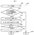
図21は、図6の競合回避ステップ605において、ネットワーク200の既存設定との競合を回避するフローチャート2100である。本実施例では、ネットワーク設定変更中に既存設定に影響を与える設定、例えば、既存の通信を遮断する設定やループを形成してしまう設定などを、既存設定と競合する設定と定義している。   FIG. 21 is a flowchart 2100 for avoiding a conflict with the existing setting of the network 200 in the conflict avoidance step 605 of FIG. In the present embodiment, a setting that affects an existing setting while the network setting is changed, for example, a setting that blocks existing communication or a setting that forms a loop, is defined as a setting that conflicts with the existing setting.

まず、開始状態2101から始まり、ステップ2102に進む。ステップ2102では、後述するパス単位の設定手順決定のフローチャート2200で、ネットワーク設定手順生成部103が、設定手順候補リストを作成し、ステップ2103に進む。   First, starting from the start state 2101, the process proceeds to step 2102. In step 2102, the network setting procedure generation unit 103 creates a setting procedure candidate list in a flowchart 2200 for determining a setting procedure for each path, which will be described later, and the process proceeds to step 2103.

ステップ2103からステップ2110は、ステップ2102で作成されたフローエントリの設定手順候補リストすべてに対する繰り返し(変数Iに格納)処理である。   Steps 2103 to 2110 are repetitive processing (stored in variable I) for all setting procedure candidate lists of flow entries created in step 2102.

ステップ2104からステップ2108は、変数Iに格納されたフローエントリリストに対する繰り返し(変数Eに格納)処理である。ステップ2105では、ネットワーク設定手順生成部103が、設定済みネットワーク管理部106から取得した設定済みネットワークモデル108に、ネットワーク設定手順生成部103が、変数Eのフローエントリを適用し、ステップ2106に進む。   Steps 2104 to 2108 are repetitive processing (stored in variable E) for the flow entry list stored in variable I. In step 2105, the network setting procedure generation unit 103 applies the flow entry of the variable E to the set network model 108 acquired from the set network management unit 106, and the process proceeds to step 2106.

ステップ2106では、ネットワーク設定手順生成部103が、後述する競合検出ステップ2700を実行し、ステップ2107に進む。ステップ2107では、ステップ2106の結果から競合がないか確認し、Yesの場合はステップ2108に、Noの場合はステップ2110に進む。   In step 2106, the network setting procedure generation unit 103 executes a conflict detection step 2700 described later, and proceeds to step 2107. In Step 2107, it is confirmed whether there is any conflict from the result of Step 2106. If Yes, the process proceeds to Step 2108, and if No, the process proceeds to Step 2110.

ステップ2108では、繰り返し処理が終わっていればステップ2109に進み、終わっていなければステップ2104に戻る。ステップ2109では、設定手順候補リストのうち、現在変数Iに格納されている通信経路と同じパスの設定手順候補リストをスキップし(変数Iを更新)、ステップ2110に進む。ステップ2110では繰り返し処理が終わっていればステップ2111に進み、終わっていなければステップ2103に戻る。   In step 2108, if the repetition process has been completed, the process proceeds to step 2109, and if not, the process returns to step 2104. In step 2109, the setting procedure candidate list of the same path as the communication path currently stored in the variable I is skipped (updates the variable I) in the setting procedure candidate list, and the process proceeds to step 2110. If it is determined in step 2110 that the repetitive processing has been completed, the process proceeds to step 2111. If not, the process returns to step 2103.

図22は、図21のパス単位設定手順決定2102のフローチャート2200である。まず、開始状態2201から始まり、ステップ2202に進む。ステップ2202からステップ2204は、フローチャート700の実行により作成された装置設定隣接リスト900に対する繰り返し処理(変数Iに格納)である。ステップ2203では、後述する再帰的なステップである装置内設定手順候補生成のフローチャート2300を実行し、ステップ2204に進む。ステップ2204では、繰り返し処理が終わっていればステップ2205に進み、終わっていなければステップ2202に戻る。   FIG. 22 is a flowchart 2200 of the path unit setting procedure determination 2102 of FIG. First, starting from the start state 2201, the process proceeds to step 2202. Step 2202 to step 2204 are repetitive processing (stored in the variable I) for the device setting adjacent list 900 created by execution of the flowchart 700. In step 2203, a flowchart 2300 for generating a setting procedure candidate in the apparatus, which is a recursive step described later, is executed, and the process proceeds to step 2204. In step 2204, if the repetition processing has been completed, the process proceeds to step 2205, and if not, the process returns to step 2202.

図23は、図22の装置内設定手順候補生成ステップ2203のフローチャート2300である。装置内設定手順候補生成は再帰的な処理であり、引数として装置A、及び設定手順候補リストを格納する2次元配列のEmatrixを取る。   FIG. 23 is a flowchart 2300 of the in-device setting procedure candidate generation step 2203 of FIG. The in-device setting procedure candidate generation is a recursive process, and the device A and the two-dimensional array Matrix that stores the setting procedure candidate list are taken as arguments.

まず、開始状態2301から始まり、ステップ2302に進む。ステップ2302では、装置内の設定手順決定のフローチャート1000で作成した装置Aに対応するフローエントリ隣接リストを変数Uに格納し、ステップ2303に進む。ステップ2303からステップ2307は、装置Aのフローエントリ隣接リストに対する繰り返し処理(変数eに格納)である。   First, starting from the start state 2301, the process proceeds to step 2302. In Step 2302, the flow entry adjacent list corresponding to the device A created in the flowchart 1000 for determining the setting procedure in the device is stored in the variable U, and the process proceeds to Step 2303. Steps 2303 to 2307 are repetitive processing (stored in variable e) for the flow entry adjacent list of apparatus A.

ステップ2304では、引数としてEmatrixと変数eを渡し、マッチ条件の包含関係を決定するフローチャート1500を実行し、ステップ2305に進む。ステップ2305ではステップ2304の結果が排他関係にあることを確認し、Yesの場合は、ステップ2306に、Noの場合はステップ2307に進む。ステップ2306では、変数Uから変数eの要素を取り除き、ステップ2307に進む。ステップ2307では、繰り返し処理が終わっていればステップ2308に進み、終わっていなければステップ2303に戻る。   In step 2304, Ematrix and the variable e are passed as arguments, and the flowchart 1500 for determining the inclusion relation of the match condition is executed, and the process proceeds to step 2305. In Step 2305, it is confirmed that the result of Step 2304 is in an exclusive relationship. If Yes, the process proceeds to Step 2306, and if No, the process proceeds to Step 2307. In step 2306, the element of variable e is removed from variable U, and the process proceeds to step 2307. In step 2307, if the repetition processing is finished, the process proceeds to step 2308, and if not, the process returns to step 2303.

ステップ2308では、後述する部分グラフ単位で順列を生成するフローチャート2400を実行し、ステップ2309に進む。ステップ2309では、順列ごとにEmatrixをコピーしたEmatrix_new[i](iは0から始まる順列の数−1の添え字)に、生成した順列を追加し、ステップ2310に進む。ステップ2310からステップ2312は、装置設定隣接リスト900から取得した、装置Aに接続されているノードに対する繰り返し処理(変数Iに格納)である。ステップ2311では、再び装置内設定手順候補生成ステップ(引数は、変数I,及びEmatrix_new[]全体)を実行し、ステップ2312に進む。ステップ2313は終了状態である。   In step 2308, a flowchart 2400 for generating a permutation in units of subgraphs described later is executed, and the process proceeds to step 2309. In step 2309, the generated permutation is added to Ematrix_new [i] (i is a subscript of the number of permutations starting from 0-1) obtained by copying Ematrix for each permutation, and the process proceeds to step 2310. Steps 2310 to 2312 are repetitive processing (stored in the variable I) for the node connected to the device A acquired from the device setting neighbor list 900. In step 2311, the in-device setting procedure candidate generation step (arguments are the variable I and the entire Matrix_new []) is executed again, and the process proceeds to step 2312. Step 2313 is an end state.

図24は、図23の部分グラフ単位で順列を生成するステップ2308のフローチャート2400である。ここでの部分グラフとは、フローエントリ隣接リスト900において、設定手順が強制されるエッジで結合されたグラフノードの集合を意味する(単独のグラフノードはグラフノード一つの集合と見なす)。部分グラフ単位で順列を生成ステップは、引数としてフローエントリ隣接リストAを取る。まず、開始状態2401から始まり、ステップ2402に進む。ステップ2402では、配列変数W、及び配列変数Tを空集合に初期化するとともに、ステップ2403に進む。ステップ2403からステップ2407は、フローエントリ隣接リストのグラフノードに対する繰り返し処理(変数Iに格納)である。   FIG. 24 is a flowchart 2400 of step 2308 for generating a permutation for each subgraph of FIG. In this case, the subgraph means a set of graph nodes connected by an edge for which the setting procedure is forced in the flow entry adjacent list 900 (a single graph node is regarded as a set of one graph node). The step of generating a permutation for each subgraph takes the flow entry adjacency list A as an argument. First, starting from the start state 2401, the process proceeds to step 2402. In step 2402, the array variable W and the array variable T are initialized to an empty set, and the process proceeds to step 2403. Steps 2403 to 2407 are an iterative process (stored in variable I) for the graph nodes in the flow entry adjacent list.

ステップ2404では、後述する部分グラフの抽出のフローチャート2500を実行し、ステップ2405に進む。ステップ2405では、配列変数Tが空か確認し、Yesであればステップ2407に、Noであればステップ2406に進む。ステップ2406では、配列変数Wに配列変数Tを追加し、ステップ2407に進む。   In step 2404, a sub-graph extraction flowchart 2500 described later is executed, and the flow advances to step 2405. In Step 2405, it is confirmed whether the array variable T is empty. If Yes, the process proceeds to Step 2407, and if No, the process proceeds to Step 2406. In Step 2406, the array variable T is added to the array variable W, and the process proceeds to Step 2407.

ステップ2407では、繰り返し処理が終わっていればステップ2408に進み、終わっていなければステップ2408に進む。ステップ2408では、後述する順列生成のフローチャート2600を実行し、ステップ2409に進む。ステップ2409は終了状態である。
If it is determined in step 2407 that the repetitive processing has been completed, the process proceeds to step 2408; otherwise, the process proceeds to step 2408. In step 2408, a permutation generation flowchart 2600 described later is executed, and the flow advances to step 2409. Step 2409 is an end state.

図25は、図24の部分グラフを抽出するステップ2404のフローチャート2500である。部分グラフを抽出するステップは、再帰的な処理で、引数としてグラフノードN及び結果格納用の配列Tを取る。まず、開始状態2501から始まり、ステップ2502に進む。ステップ2502では、グラフノードNが訪問状態か確認し、Yesの場合はステップ2508に、Noの場合はステップ2503に進む。ステップ2503では配列TにグラフノードNを追加し、ステップ2504に進む。ステップ2504では、グラフノードNを訪問状態に変更し、ステップ2505に進む。ステップ2505からステップ2507はグラフノードNの隣接グラフノードすべてに対する繰り返し処理(変数Iに格納)である。   FIG. 25 is a flowchart 2500 of step 2404 for extracting the subgraph of FIG. The step of extracting a subgraph is a recursive process, and takes a graph node N and an array T for storing results as arguments. First, starting from the start state 2501, the process proceeds to step 2502. In step 2502, it is confirmed whether the graph node N is in the visited state. If yes, the process proceeds to step 2508. If no, the process proceeds to step 2503. In step 2503, the graph node N is added to the array T, and the process proceeds to step 2504. In step 2504, the graph node N is changed to the visited state, and the process proceeds to step 2505. Steps 2505 to 2507 are an iterative process (stored in variable I) for all graph nodes adjacent to graph node N.

ステップ2506は、再び部分グラフ抽出ステップを引数として、変数I及び配列Tを渡して実行し、ステップ2507に進む。ステップ2507では、繰り返し処理が終わっていればステップ2508に進み、終わっていなければステップ2508に進む。ステップ2508は終了状態である。   Step 2506 executes again by passing the variable I and array T with the subgraph extraction step as an argument, and proceeds to step 2507. In step 2507, if the repetitive processing is completed, the process proceeds to step 2508, and if not, the process proceeds to step 2508. Step 2508 is an end state.

図26は、図24の順列を生成するステップ2408のフローチャート2600である。順列の生成ステップは、再帰的な処理で、引数として、部分グラフの配列A,及び結果を格納する配列Pを取る。まず、開始状態2601から始まり、ステップ2602に進む。ステップ2602では、配列Pを配列Aのサイズ分だけ、配列P[i] (iは添え字で要素i番目を意味)を複製し、ステップ2603に進む。ステップ2603からステップ2606は、配列Aの要素に対する繰り返し処理(変数Iに格納)である。   FIG. 26 is a flowchart 2600 of step 2408 for generating the permutation of FIG. The permutation generation step is a recursive process and takes an array A of subgraphs and an array P for storing the results as arguments. First, starting from the start state 2601, the process proceeds to step 2602. In step 2602, the array P [i] (where i is a subscript means element i) is duplicated by the size of the array A, and the process proceeds to step 2603. Steps 2603 to 2606 are an iterative process (stored in variable I) for the elements of array A.

ステップ2604では、配列P[i]に変数Iを追加し、ステップ2605に進む。ステップ2605では、再び順列の生成ステップを、引数としてA−{I}、及び配列P[i]を渡して実行し、ステップ2606に進む。ステップ2606では繰り返し処理が終わっていればステップ2607に進み、終わっていなければステップ2603に戻る。ステップ2607は終了状態である。   In Step 2604, the variable I is added to the array P [i], and the process proceeds to Step 2605. In step 2605, the permutation generation step is executed again by passing A- {I} and the array P [i] as arguments, and the process proceeds to step 2606. If it is determined in step 2606 that the repetitive processing has been completed, the process proceeds to step 2607. If not, the process returns to step 2603. Step 2607 is an end state.

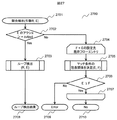
図27は、図21の競合検出ステップ2106のフローチャート2700である。競合検出のステップは、引数として、フローエントリEを取る。まず、開始状態2701から始まり、ステップ2702に進む。ステップ2702では、フローエントリEのアクションがoutputか確認し、Yesの場合はステップ2703に、Noの場合はステップ2704に進む。   FIG. 27 is a flowchart 2700 of the conflict detection step 2106 of FIG. The conflict detection step takes a flow entry E as an argument. First, starting from the start state 2701, the process proceeds to step 2702. In step 2702, it is confirmed whether the action of the flow entry E is output. If Yes, the process proceeds to step 2703, and if No, the process proceeds to step 2704.

ステップ2703では、後述するループ検出のフローチャート2800を実行し、ステップ2708に進む。ステップ2704からステップ2707は、フローエントリEが設定される通信装置に既に設定されているフローエントリに対する繰り返し処理(変数Fに格納)である。フローエントリEの設定先は、フローエントリEのIDプロパティをもとにネットワーク設定データ400を検索し取得する。設定先に既に設定されているフローエントリは、設定済みネットワークモデル108から取得する。   In step 2703, a loop detection flowchart 2800, which will be described later, is executed, and the flow advances to step 2708. Steps 2704 to 2707 are repetitive processing (stored in variable F) for the flow entry already set in the communication apparatus in which flow entry E is set. The setting destination of the flow entry E searches and acquires the network setting data 400 based on the ID property of the flow entry E. The flow entry already set in the setting destination is acquired from the set network model 108.

ステップ2705では、引数としてEとFを指定してマッチ条件の包含関係を決定するフローチャート1500を実行し、ステップ2706に進む。ステップ2706では、ステップ2705の結果が排他関係かを確認し、Yesの場合はステップ2707に進み、Noの場合はステップ2709に進む。ステップ2707では、繰り返し処理が終わっていればステップ2710に進み、終わっていなければステップ2704に戻る。   In step 2705, the flowchart 1500 is executed in which E and F are specified as arguments to determine the inclusion relation of the match condition, and the process proceeds to step 2706. In step 2706, it is confirmed whether the result of step 2705 is an exclusive relationship. If yes, the process proceeds to step 2707, and if no, the process proceeds to step 2709. In step 2707, if the repetition processing has been completed, the process proceeds to step 2710. If not, the process returns to step 2704.

ステップ2708では、ステップ2703のループ検出結果を呼び出し元に返し終了する。ステップ2709では競合を検出したErrorを呼び出し元に返し終了する。ステップ2710では、競合未検出のNoを呼び出し元に返し終了する。   In step 2708, the loop detection result in step 2703 is returned to the caller, and the process ends. In step 2709, the error detected in the error is returned to the caller and the process ends. In step 2710, No which has not been detected as a conflict is returned to the caller and the process ends.

図28は、図27のループ検出ステップ2703のフローチャート2800である。ループ検出のステップは再帰的な処理であり、引数として、フローエントリR、フローエントリEを取る。まず、開始状態2801から始まり、ステップ2802に進む。ステップ2802からステップ2812は、フローエントリEのアクションoutputの出力先に対する繰り返し処理(変数Pに格納)である。出力先がNormalの場合、フローエントリEのIDをもとに、ネットワーク設定データから設定先装置を特定し、設定済みネットワークモデル108から該当装置に設定されている同一VLANに属する出力ポートを得る。   FIG. 28 is a flowchart 2800 of the loop detection step 2703 of FIG. The loop detection step is a recursive process, and takes flow entry R and flow entry E as arguments. First, starting from the start state 2801, the process proceeds to step 2802. Steps 2802 to 2812 are repetitive processing (stored in the variable P) for the output destination of the action output of the flow entry E. When the output destination is Normal, the setting destination device is specified from the network setting data based on the ID of the flow entry E, and the output port belonging to the same VLAN set in the corresponding device is obtained from the set network model 108.

ステップ2803では、ネットワーク構成データ500から変数Pが接続されている装置Xを特定し、ステップ2804に進む。ステップ2804からステップ2811は、装置Xに設定されてフローエントリに対する繰り返し処理(変数e)である。装置Xに設定されているフローエントリは、設定済みネットワークモデル108から取得する。ステップ2805は、フローエントリEとフローエントリeが同一か確認し、Yesの場合はステップ2814に、Noの場合はステップ2806に進む。   In step 2803, the device X to which the variable P is connected is identified from the network configuration data 500, and the process proceeds to step 2804. Steps 2804 to 2811 are repetitive processing (variable e) for the flow entry set in the device X. The flow entry set for the device X is acquired from the set network model 108. In Step 2805, it is confirmed whether or not the flow entry E and the flow entry e are the same. If Yes, the process proceeds to Step 2814. If No, the process proceeds to Step 2806.

ステップ2806では、引数としてEとeを指定してマッチ条件の包含関係を決定するフローチャート1500を実行し、ステップ2807に進む。ステップ2807ではステップ2806の結果が排他関係か確認し、Yesの場合はステップ2808に、Noの場合はステップ2811に進む。   In step 2806, a flowchart 1500 is executed in which E and e are specified as arguments to determine the inclusion relation of the match condition, and the process proceeds to step 2807. In step 2807, it is confirmed whether or not the result of step 2806 is an exclusive relationship. If Yes, the process proceeds to Step 2808, and if No, the process proceeds to Step 2811.

ステップ2808では、フローエントリeのアクションにoutputが含まれるかを確認し、Yesの場合はステップ2809に進み、Noの場合はステップ2811に進む。ステップ2809では、引数にフローエントリRとフローエントリeを指定して再びループ検出のステップを実行し、ステップ2811に進む。   In Step 2808, it is confirmed whether or not output is included in the action of the flow entry e. If Yes, the process proceeds to Step 2809, and if No, the process proceeds to Step 2811. In step 2809, flow entry R and flow entry e are designated as arguments, the loop detection step is executed again, and the flow proceeds to step 2811.

ステップ2811では、繰り返し処理が終わっていればステップ2812に進み、終わっていなければステップ2804に戻る。ステップ2812では、繰り返し処理が終わっていればステップ2813に進み、終わっていなければステップ2802に戻る。   In step 2811, the process proceeds to step 2812 if the repetition process is completed, and returns to step 2804 if it is not completed. In step 2812, the process proceeds to step 2813 if the repetition process has been completed, and returns to step 2802 if it has not been completed.

ステップ2813では、呼び出し元にNoを返し終了する。ステップ2814では、呼び出し元にYesを返し終了する。   In step 2813, No is returned to the caller and the process ends. In step 2814, Yes is returned to the caller and the process ends.

図21〜図28で説明したように、ネットワーク設定手順生成部は、生成された新規ネットワーク設定の設定手順のうち、入力装置から入力され、あるいは記憶装置に記憶されている設定済みのネットワーク設定データと、競合を生じない設定手順を選択する。   As described with reference to FIGS. 21 to 28, the network setting procedure generation unit sets network setting data that has been input from the input device or stored in the storage device among the generated setting procedures for new network settings. And a setting procedure that does not cause a conflict is selected.

具体的には、フローチャート2100において、設定手順の候補から既存設定との競合を確認した設定手順を選択することによりネットワーク設定変更中のループ回避が可能になり、また既存の設定に影響を与える矛盾した設定内容を検出することが可能になり、信頼性の高いネットワーク構成変更が実現できる。   Specifically, in the flowchart 2100, by selecting a setting procedure that has confirmed a conflict with an existing setting from candidate setting procedures, it is possible to avoid a loop during a network setting change, and a conflict that affects the existing setting. It is possible to detect the set contents, and to realize a highly reliable network configuration change.

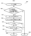
図29は、図6の設定先依存設定手順決定ステップ606のフローチャート2900である。ここでは、ネットワーク設定データ400に記載された設定記憶部126の情報をもとに、異なる設定記憶部126に同時に設定できる設定手順を作成する。まず、開始状態2901から始まり、ステップ2902に進む。   FIG. 29 is a flowchart 2900 of the setting destination dependency setting procedure determination step 606 of FIG. Here, based on information in the setting storage unit 126 described in the network setting data 400, a setting procedure that can be set simultaneously in different setting storage units 126 is created. First, starting from the start state 2901, the process proceeds to step 2902.

ステップ2902からステップ2904は、装置設定隣接リスト900のグラフノードに対する繰り返し処理(変数Iに格納)である。   Steps 2902 to 2904 are repetitive processing (stored in variable I) for the graph nodes in the apparatus setting adjacent list 900.

ステップ2903では、後述する装置内設定先依存設定手順決定のフローチャート3000を実行し、ステップ2904に進む。   In step 2903, a flowchart 3000 for determining the in-device setting destination dependency setting procedure described later is executed, and the process proceeds to step 2904.

ステップ2904では、繰り返し処理が終わっていればステップ2905に進み、終わっていなければステップ2902に戻る。   In step 2904, if the repetition processing is completed, the process proceeds to step 2905. If not, the process returns to step 2902.

ステップ2905では、装置設定隣接リスト900と、後述するフローチャート2900により生成されたフローエントリ隣接リストをネットワーク設定グラフとしてまとめ、ネットワーク設定データ400とともに、ネットワーク設定実行キュー104に保存し、ステップ2906に進む。ステップ2906は終了状態である。   In step 2905, the device setting neighbor list 900 and a flow entry neighbor list generated by a flowchart 2900 described later are collected as a network setting graph, stored together with the network setting data 400 in the network setting execution queue 104, and the process proceeds to step 2906. Step 2906 is an end state.

図30は、図29の設定先に依存した装置内における設定手順を決定するステップ2903のフローチャート3000である。ステップ2903は、再帰的な処理であり、引数として通信装置Aを取る。まず、開始状態3001から始まり、ステップ3002に進む。   FIG. 30 is a flowchart 3000 of step 2903 for determining a setting procedure in the apparatus depending on the setting destination of FIG. Step 2903 is a recursive process and takes the communication device A as an argument. First, starting from the start state 3001, the process proceeds to step 3002.

ステップ3002では、ネットワーク設定データ400から、装置Aのフローエントリ隣接リストのグラフノードすべての設定先を取得し、ステップ3003に進む。ステップ3003では、ステップ3002で取得したフローエントリ隣接グラフノードの設定先をもとに、グラフノードの順番を同じ設定先(格納先)が連続しないように並び替え、ステップ3004に進む。   In step 3002, the setting destinations of all graph nodes in the flow entry adjacent list of apparatus A are acquired from the network setting data 400, and the process proceeds to step 3003. In step 3003, based on the setting destination of the flow entry adjacent graph node acquired in step 3002, the order of the graph nodes is rearranged so that the same setting destination (storage destination) does not continue, and the process proceeds to step 3004.

ステップ3004からステップ3010は通信装置Aのフローエントリ隣接リストのグラフノードに対する繰り返し処理(変数Eに格納)である。   Steps 3004 to 3010 are repetitive processing (stored in the variable E) for the graph node of the flow entry adjacent list of the communication apparatus A.

ステップ3005では、変数Eの隣接グラフノードが複数あるか確認し、Yesの場合はステップ3006に、Noの場合はステップ3007に進む。   In step 3005, it is confirmed whether there are a plurality of adjacent graph nodes of the variable E. If Yes, the process proceeds to step 3006. If No, the process proceeds to step 3007.

ステップ3006では、ステップ3002で取得した変数Eの隣接グラフノードの設定先をもとに、隣接グラフノードの順番を同じ設定先(格納先)が連続しないように並び替え、ステップ3007に進む。   In step 3006, based on the setting destination of the adjacent graph node of the variable E acquired in step 3002, the order of the adjacent graph nodes is rearranged so that the same setting destination (storage destination) does not continue, and the process proceeds to step 3007.

ステップ3007からステップ3009は、変数Eに含まれるoutputアクションの出力先通信装置に対する繰り返し処理(変数Iに格納)である。outputアクションの出力先通信装置は、ネットワーク構成データ500から取得する。ステップ3008では、引数に変数Iを指定して、装置内設定先依存設定手順決定のフローチャート3000を実行し、ステップ3009に進む。ステップ3009では繰り返し処理が終了していればステップ3010に進み、終了していなければステップ3007に戻る。ステップ3010では、繰り返し処理が終了していればステップ3011に進み、終了していなければステップ3004に戻る。ステップ3011は終了状態である。   Steps 3007 to 3009 are repetitive processing (stored in variable I) for the output destination communication device of the output action included in variable E. The output destination communication device of the output action is acquired from the network configuration data 500. In step 3008, the variable I is specified as an argument, the flowchart 3000 for determining the in-device setting destination dependency setting procedure is executed, and the process proceeds to step 3009. If it is determined in step 3009 that the repetitive processing has been completed, the process proceeds to step 3010. If not, the process returns to step 3007. In step 3010, if the repetition process has been completed, the process proceeds to step 3011. If not, the process returns to step 3004. Step 3011 is an end state.

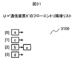
図31は、図6の装置内設定先依存設定手順決定ステップ606のフローチャート3000実行後の、通信装置X120(1)のフローエントリ隣接リストの例である。   FIG. 31 is an example of the flow entry adjacency list of the communication device X 120 (1) after execution of the flowchart 3000 of the in-device setting destination dependency setting procedure determination step 606 of FIG.

このように、装置内設定先依存設定手順決定のフローチャート3000に基づいて、設定先の影響を考慮した設定手順を生成することにより、設定実行の衝突を回避することができ、設定実行時間の短縮が実現される。   In this way, by generating the setting procedure that takes into account the influence of the setting destination based on the flowchart 3000 for determining the setting destination-dependent setting procedure in the apparatus, it is possible to avoid the collision of the setting execution and shorten the setting execution time. Is realized.

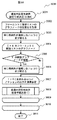
図32は、図6のシーケンス番号付与ステップ607のフローチャート3200である。まず、開始状態3201から始まり、ステップ3202に進む。ステップ3202からステップ3207は、装置設定リスト900のグラフノードに対する繰り返し処理(変数Iに格納)である。ステップ3203からステップ3206は、変数Iのフローエントリ隣接リストのグラフノードのうち、先頭手順のグラフノードに対する繰り返し処理(変数Eに格納)である。ステップ3204は、後述する装置内シーケンス番号を付与するフローチャート3300を実行し、ステップ3205に進む。   FIG. 32 is a flowchart 3200 of sequence number assigning step 607 in FIG. First, starting from the start state 3201, the process proceeds to step 3202. Steps 3202 to 3207 are repetitive processing (stored in the variable I) for the graph nodes of the device setting list 900. Steps 3203 to 3206 are repetitive processing (stored in variable E) for the graph node of the head procedure among the graph nodes of the flow entry adjacent list of variable I. In step 3204, a flowchart 3300 for assigning an in-device sequence number to be described later is executed, and the flow proceeds to step 3205.

ステップ3205では、変数Iのうち最終手順のグラフノードの次にバリア命令を追加し、ステップ3206に進む。ステップ3206では繰り返し処理が終わっていればステップ3207に進み、終わっていなければステップ3203に戻る。ステップ3207では繰り返し処理が終わっていればステップ3208に進み、終わっていなければステップ3202に戻る。ステップ3208は終了状態である。   In step 3205, a barrier instruction is added next to the graph node of the final procedure in the variable I, and the process proceeds to step 3206. If it is determined in step 3206 that the repetitive processing has been completed, the process proceeds to step 3207. If not, the process returns to step 3203. If it is determined in step 3207 that the repeated processing has been completed, the process proceeds to step 3208. If not, the process returns to step 3202. Step 3208 is an end state.

図33は、図32の装置内シーケンス番号を付与するステップ3204のフローチャート3300である。装置内シーケンス番号の付与は再帰的な処理であり、引数にフローエントリEとシーケンス番号nを取る。まず、開始状態3301から始まり、ステップ3302に進む。   FIG. 33 is a flowchart 3300 of step 3204 for assigning the in-device sequence number of FIG. The assignment of the in-device sequence number is a recursive process and takes a flow entry E and a sequence number n as arguments. First, starting from the start state 3301, the process proceeds to step 3302.

ステップ3302ではフローエントリEにシーケンス番号nを付与し、ステップ3303に進む。ステップ3303からステップ3305はフローエントリEの隣接グラフノードに対する繰り返し処理(変数Iに格納)である。ステップ3304は、引数に変数I及びn+1を指定し、再び装置内シーケンス番号の付与のフローチャートを実行する。   In Step 3302, the sequence number n is assigned to the flow entry E, and the process proceeds to Step 3303. Steps 3303 to 3305 are an iterative process (stored in variable I) for the adjacent graph node of flow entry E. In step 3304, variables I and n + 1 are designated as arguments, and the flowchart of assigning the in-device sequence number is executed again.

ステップ3305では、繰り返し処理が終わっていればステップ3306に進み、終わっていなければステップ3303に戻る。ステップ3306は終了状態である。   In step 3305, if the repetition processing is finished, the process proceeds to step 3306, and if not, the process returns to step 3303. Step 3306 is an end state.

図32〜図33で説明したように、本実施例では、生成された設定手順に設定順序を表すシーケンス番号を付与する。また、通信装置単位で、設定完了の応答を要求する命令を追加する。   As described with reference to FIGS. 32 to 33, in the present embodiment, a sequence number representing the setting order is assigned to the generated setting procedure. In addition, a command for requesting a setting completion response is added for each communication device.

このように、通信装置120ごとフローエントリにシーケンス番号を付与することで、通信装置120内で同じシーケンス番号を持っている設定を並列に実行できることが識別できるので並列実行により、設定実行時間の短縮化につながる。   In this way, by assigning a sequence number to the flow entry for each communication device 120, it is possible to identify that settings having the same sequence number in the communication device 120 can be executed in parallel. Leading to

また、通信装置120はシーケンス番号に基づいて独立して正しい設定手順で設定実行が可能になるため、制御装置100が逐次フローエントリの設定実行が終了したか確認する必要がなくなり、設定完了確認に要する時間を削減できる。例えば、ネットワーク設定データ400の通信装置X120(1)には4つのフローエントリがあるため、仮に、コンフィギュレーションネットワークが高遅延なWAN、例えば100msの遅延を持つネットワーク場合、従来技術では、設定完了確認に、100ms×2(往復)×4=800ms必要とするのに対して、本実施形態では、100ms×2(往復)=200msで済み、設定実行時間の短縮を図ることができる。   In addition, since the communication device 120 can perform setting execution independently with the correct setting procedure based on the sequence number, it is not necessary for the control device 100 to confirm whether or not the sequential flow entry setting has been completed. Time required can be reduced. For example, since there are four flow entries in the communication device X120 (1) of the network setting data 400, if the configuration network is a high-delay WAN, for example, a network having a delay of 100 ms, the conventional technology confirms the setting completion. In contrast, 100 ms × 2 (reciprocation) × 4 = 800 ms is required, but in this embodiment, 100 ms × 2 (reciprocation) = 200 ms is required, and the setting execution time can be shortened.

図34は、制御装置100における図6の設定実行ステップ608のフローチャートである。まず、開始状態3401から始まり、ステップ3402に進む。   FIG. 34 is a flowchart of the setting execution step 608 in FIG. First, starting from the start state 3401, the process proceeds to step 3402.

ステップ3402では、ネットワーク設定実行部105が、ネットワーク設定実行キュー104からネットワーク設定グラフGとネットワーク設定データCを読み出し、ステップ3403に進む。   In step 3402, the network setting execution unit 105 reads the network setting graph G and the network setting data C from the network setting execution queue 104, and the process proceeds to step 3403.

ステップ3403では、ネットワーク設定実行部105が、装置設定の並列実行を行い、ステップ3404に進む。ステップ3404は終了状態である。   In step 3403, the network setting execution unit 105 performs parallel execution of device settings, and proceeds to step 3404. Step 3404 is an end state.

図35は、ネットワーク設定実行部105における、図6の装置設定の並列実行ステップ609のフローチャート3500である。装置設定の並列実行は再帰的な処理であり、引数として装置設定隣接リスト(図9参照)のグラフノードを取る。まず、開始状態3501から始まり、ステップ3502に進む。
ステップ3502では、ネットワーク設定実行部105が、装置設定隣接リストのグラフノードのうち、互いに隣接していないグラフノードAn(nは自然数で、最大は互いに隣接していないグラフノードの数)を引数に、後述する装置設定の実行のフローチャート3600(図36参照)を実行し、ステップ3503に進む。
FIG. 35 is a flowchart 3500 of the apparatus setting parallel execution step 609 of FIG. Parallel execution of device setting is a recursive process, and takes a graph node of the device setting neighbor list (see FIG. 9) as an argument. First, starting from the start state 3501, the process proceeds to step 3502.
In step 3502, the network setting execution unit 105 uses, as an argument, graph nodes An that are not adjacent to each other (n is a natural number and the maximum is the number of graph nodes that are not adjacent to each other) among the graph nodes in the device setting adjacent list. Then, a flowchart 3600 (see FIG. 36) of execution of device setting, which will be described later, is executed, and the process proceeds to step 3503.

ステップ3503は、並列に実行したステップ3502それぞれ独立に実行される。ステップ3503では、ネットワーク設定実行部105が、Anの隣接ノードすべてを引数に、再び装置設定の並列実行を呼び出し、ステップ3504に進む。ステップ3504は終了状態である。   Step 3503 is executed independently of each step 3502 executed in parallel. In step 3503, the network setting execution unit 105 calls again parallel execution of device setting using all the adjacent nodes of An as arguments, and the process proceeds to step 3504. Step 3504 is an end state.

図36は、図35の装置設定の実行ステップ3502のフローチャート3600で、引数として装置Aを取る。まず、開始状態3601から始まり、ステップ3602に進む。ステップ3602では、ネットワーク設定実行部105が、後述するフローエントリ設定の並列実行3700を行いステップ3603に進む。ステップ3603は終了状態である。   FIG. 36 is a flowchart 3600 of the apparatus setting execution step 3502 in FIG. 35, and takes apparatus A as an argument. First, starting from the start state 3601, the process proceeds to step 3602. In step 3602, the network setting execution unit 105 performs flow entry setting parallel execution 3700, which will be described later, and proceeds to step 3603. Step 3603 is an end state.

図37は、図36のフローエントリ設定の並列実行ステップ3602のフローチャート3700である。フローエントリ設定の並列実行は再帰的処理であり、引数にフローエントリ隣接リストのグラフノードを取る。まず、開始状態3701から始まり、ステップ3702に進む。   FIG. 37 is a flowchart 3700 of the flow entry setting parallel execution step 3602 of FIG. Parallel execution of flow entry setting is a recursive process, and takes a graph node of a flow entry adjacent list as an argument. First, starting from the start state 3701, the process proceeds to step 3702.

ステップ3702は、互いに隣接していないフローエントリのグラフノードAn(nは自然数で、最大は互いに隣接していないグラフノードの数)分、並列に実行される。   Step 3702 is executed in parallel by the number of graph nodes An (n is a natural number, and the maximum is the number of graph nodes that are not adjacent to each other) of flow entries that are not adjacent to each other.

ステップ3702では、ネットワーク設定実行部105が、ネットワーク設定データCからAnに対応する設定データXnを取得し、ステップ3703に進む。   In step 3702, the network setting execution unit 105 acquires setting data Xn corresponding to An from the network setting data C, and the process proceeds to step 3703.

ステップ3703では、ネットワーク設定実行部105が、設定データXnを対象の通信装置120に送信し、ステップ3704に進む。   In step 3703, the network setting execution unit 105 transmits the setting data Xn to the target communication device 120, and the process proceeds to step 3704.

ステップ3704では、ネットワーク設定実行部105が、Anに送信済みフラグを設定し、ステップ3705に進む。   In step 3704, the network setting execution unit 105 sets a transmitted flag in An, and the process proceeds to step 3705.

ステップ3705では、Xnがバリア命令か確認し、Yesの場合はステップ3706に進み、Noの場合はステップ3707に進む。   In Step 3705, it is confirmed whether Xn is a barrier command. If Yes, the process proceeds to Step 3706. If No, the process proceeds to Step 3707.

ステップ3706では、バリア命令を送信した通信装置120からバリア応答が戻ってくるのを待ち、戻ってきたらステップ3707に進む。   In step 3706, the process waits for a barrier response to be returned from the communication apparatus 120 that has transmitted the barrier command.

ステップ3707では、Anの隣接ノードで送信済みフラグが設定されていないグラフノードを引数に、フローエントリ設定の並列実行を呼び出し、ステップ3708に進む。ステップ3708は終了状態である。   In step 3707, parallel execution of flow entry setting is called with a graph node in which the transmitted flag is not set in an adjacent node of An as an argument, and the process proceeds to step 3708. Step 3708 is an end state.

以上の実施例では、ネットワーク設定データに含まれる設定の、通信装置の保存先を検出する。そして、新規ネットワーク設定に含まれる複数の設定が同時に通信装置に設定できるように設定手順を生成する。このために、ネットワーク設定実行部105がネットワーク設定グラフに基づき設定を実行する。これにより、装置単位及び装置内のフローエントリ単位で、ネットワークに障害を起こさない手順で設定を並列実行できるため、安全に制御装置の設定実行時間の短縮を図れる。また、本実施例のネットワーク設定実行部は、生成された設定手順に従い、通信装置に設定を実行し、設定完了の応答を要求する命令を送信した場合は応答を待つように構成することができる。   In the above embodiment, the storage destination of the communication device for the settings included in the network setting data is detected. Then, a setting procedure is generated so that a plurality of settings included in the new network setting can be simultaneously set in the communication device. For this purpose, the network setting execution unit 105 executes setting based on the network setting graph. Thereby, setting can be executed in parallel in a procedure that does not cause a failure in the network in units of devices and in units of flow entries in the device, so that the setting execution time of the control device can be shortened safely. In addition, the network setting execution unit according to the present embodiment can be configured to execute the setting to the communication apparatus according to the generated setting procedure, and to wait for a response when a command requesting a setting completion response is transmitted. .

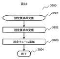
図38は、通信装置120における、図6の設定処理ステップ609の一部である、設定要求受信のフローチャート3800である。まず、開始状態3801から始まり、ステップ3802に進む。   FIG. 38 is a flowchart 3800 for receiving a setting request, which is a part of the setting processing step 609 in FIG. First, starting from the start state 3801, the process proceeds to step 3802.

ステップ3802では、設定実行部122が、制御装置100からの設定要求を受信し、ステップ3803に進む。   In step 3802, the setting execution unit 122 receives a setting request from the control device 100 and proceeds to step 3803.

ステップ3803では、設定実行部122が設定キュー123に、設定要求を格納し、ステップ3804に進む。ステップ3804は終了状態である。   In step 3803, the setting execution unit 122 stores the setting request in the setting queue 123, and the process proceeds to step 3804. Step 3804 is an end state.

図39は、通信装置120における、図6の設定処理ステップ609の一部である、設定実行のフローチャート3900である。まず、開始状態3901から始まり、ステップ3902に進む。   FIG. 39 is a flowchart 3900 of setting execution, which is a part of the setting processing step 609 of FIG. First, starting from the start state 3901, the process proceeds to step 3902.

ステップ3902では、n個ある(nは自然数)設定実行部(図1の122)の設定実行4000が並列に実行され、ステップ3903に進む。ステップ3903は終了状態である。   In step 3902, n setting execution units (122 in FIG. 1) of n (n is a natural number) setting execution 4000 are executed in parallel, and the process proceeds to step 3903. Step 3903 is an end state.

図40は、図6の設定処理ステップ609の一部である、設定実行部122における設定実行のフローチャートである。まず、開始状態4001から始まり、ステップ4002に進む。   FIG. 40 is a flowchart of setting execution in the setting execution unit 122, which is a part of the setting processing step 609 in FIG. First, starting from the start state 4001, the process proceeds to step 4002.

ステップ4002では、設定実行部122が、実行シーケンス番号nを1に初期化し、ステップ4003に進む。   In step 4002, the setting execution unit 122 initializes the execution sequence number n to 1, and proceeds to step 4003.

ステップ4003では、設定実行部122が、設定キューからシーケンス番号nの設定を取得し、ステップ4004に進む。   In step 4003, the setting execution unit 122 acquires the setting of the sequence number n from the setting queue, and proceeds to step 4004.

ステップ4004では、設定実行部122が、受信した設定を設定記憶部に保存し、ステップ4005に進む。   In step 4004, the setting execution unit 122 stores the received setting in the setting storage unit, and the process proceeds to step 4005.

ステップ4005では、設定実行部122が、実行シーケンス番号nに1を加え、ステップ4006に進む。   In step 4005, the setting execution unit 122 adds 1 to the execution sequence number n and proceeds to step 4006.

ステップ4006では、設定実行部122が、設定キューが空か確認し、Yesの場合は、ステップ4007に進み、Noの場合はステップ4003に進む。ステップ4007は終了状態である。   In step 4006, the setting execution unit 122 checks whether the setting queue is empty. If yes, the process proceeds to step 4007. If no, the process proceeds to step 4003. Step 4007 is an end state.

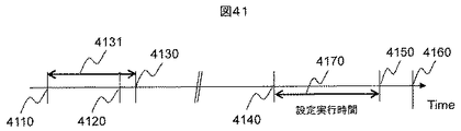
図41は、本発明の実施形態における、ネットワーク構成変更のタイムラインを示している。   FIG. 41 shows a network configuration change timeline in the embodiment of the present invention.

図41のネットワーク設計開始時刻4110は、オペレータが要求仕様に基づきネットワークを構成する装置それぞれの設定内容を検討し、ネットワーク設定データ300、およびネットワーク構成データ500の作成に着手(図6のステップ602)した時刻である。オペレータは設計作業を終えると、ネットワーク設定データ300をネットワーク設定キュー101に、ネットワーク構成データ500をネットワーク構成DB102に格納する。   41 starts the creation of the network setting data 300 and the network configuration data 500 (step 602 in FIG. 6). The network design start time 4110 in FIG. It is time. When the operator finishes the design work, the network setting data 300 is stored in the network setting queue 101 and the network configuration data 500 is stored in the network configuration DB 102.

設定手順生成開始時刻4120は、ネットワーク設定手順生成部103がネットワーク設定キュー101からネットワーク設定データ300を読み出し、図6のステップ603を開始した時刻である。   The setting procedure generation start time 4120 is the time when the network setting procedure generation unit 103 reads the network setting data 300 from the network setting queue 101 and starts step 603 in FIG.

ネットワーク設計終了時刻4130は、ネットワーク設定手順生成部103により生成されたネットワーク設定グラフとネットワーク設定データが、ネットワーク設定実行キュー104に格納された時刻である。   The network design end time 4130 is the time when the network setting graph and the network setting data generated by the network setting procedure generating unit 103 are stored in the network setting execution queue 104.

以上でネットワークの設定準備4131が終わり、システムは予定されたネットワーク構成変更開始時刻4140まで待機する。ネットワークの設定準備4131の間は、ネットワークは運用可能である。   Thus, the network setting preparation 4131 is completed, and the system waits until the scheduled network configuration change start time 4140. The network can be operated during the network setting preparation 4131.

ネットワーク構成変更開始時刻4140は、ネットワーク設定データに記載された設定開始時刻であり、ネットワーク設定実行部105が、図34のフローチャート3400に示す設定を開始した時刻である。   The network configuration change start time 4140 is a setting start time described in the network setting data, and is a time when the network setting execution unit 105 starts the setting shown in the flowchart 3400 of FIG.

ネットワーク検証開始時刻4150は、フローチャート3400に示す設定が終わった後、ネットワークが正しく設定されたか検証を開始する時刻である。サービスイン4160は、検証後実際にネットワークの運用を開始できる時刻である。   The network verification start time 4150 is a time at which verification is started to confirm whether the network has been correctly set after the setting shown in the flowchart 3400 is completed. The service-in 4160 is a time when the network operation can actually be started after the verification.

本発明は、ネットワーク設計時に設定手順を生成し、図41の設定実行時間4170を短縮することで、高速なネットワーク構成変更を可能とする。設定実行時間は、構成中のネットワークが利用できない時間であり、設定実行時間4170を短縮することで、ネットワーク資源の利用効率を向上させることができる。   The present invention enables a high-speed network configuration change by generating a setting procedure at the time of network design and shortening the setting execution time 4170 of FIG. The setting execution time is a time during which the network being configured cannot be used, and the use efficiency of network resources can be improved by reducing the setting execution time 4170.

本実施例は、実施例1における制御装置の設定実行時間を短縮するものである。図1を参照し、実施例1から変更がある構成についてのみ、以下に示す。   In the present embodiment, the setting execution time of the control device in the first embodiment is shortened. With reference to FIG. 1, only the configuration changed from the first embodiment will be described below.

図42は、実施例2におけるネットワーク設定システムの構成例を示すブロック図である。本実施例では、制御装置100を複数備える。本実施例では、複数の制御装置100は、互いに通信できるようにコンフィギュレーションネットワーク110に接続しているが、互いに通信できれば、コンフィギュレーションネットワーク110以外のネットワークを追加して接続してもよい。   FIG. 42 is a block diagram illustrating a configuration example of the network setting system according to the second embodiment. In this embodiment, a plurality of control devices 100 are provided. In the present embodiment, the plurality of control devices 100 are connected to the configuration network 110 so that they can communicate with each other. However, as long as they can communicate with each other, a network other than the configuration network 110 may be additionally connected.

図43は、変更後の制御装置における設定実行のフローチャート4300である。ステップ3401からステップ3402(図34参照)は、実施例1と同様である。   FIG. 43 is a flowchart 4300 of setting execution in the control device after the change. Steps 3401 to 3402 (see FIG. 34) are the same as those in the first embodiment.

ステップ4301では、ネットワーク設定実行部105が、読み出したネットワーク設定グラフに分割済み設定フラグが設定されているか確認し、Yesの場合はステップ4305に、Noの場合はステップ4302に進む。   In step 4301, the network setting execution unit 105 checks whether the divided setting flag is set in the read network setting graph. If yes, the process proceeds to step 4305. If no, the process proceeds to step 4302.

ステップ4302では、ネットワーク設定実行部105がネットワーク設定グラフGを分割しステップ4303に進む。本実施例では、装置設定リストのルートノード、すなわち、ネットワークの最下流に位置する通信装置の集合を制御装置数で分割している。制御装置数で割り切れない場合は余りを任意の制御装置に割り当ててもよい。分割は、均等分割の他、制御装置の負荷や、制御装置が管理する通信装置の数に基づいてもよい。   In step 4302, the network setting execution unit 105 divides the network setting graph G and proceeds to step 4303. In this embodiment, a set of communication devices located at the root node of the device setting list, that is, the most downstream side of the network is divided by the number of control devices. If it is not divisible by the number of control devices, the remainder may be allocated to an arbitrary control device. The division may be based on the load of the control device or the number of communication devices managed by the control device, in addition to the equal division.

ステップ4303では、ネットワーク設定実行部105が、分割されたネットワーク設定グラフG[i](iは添え字)それぞれに、分割済みのフラグを設定し、ステップ4304に進む。   In step 4303, the network setting execution unit 105 sets a divided flag for each of the divided network setting graphs G [i] (i is a subscript), and the process proceeds to step 4304.

ステップ4304では、自身を含む制御装置のネットワーク設定実行キューに分割したネットワーク設定グラフG[i]を格納し、ステップ4305に進む。   In step 4304, the network setting graph G [i] divided into the network setting execution queue of the control device including itself is stored, and the process proceeds to step 4305.

ステップ4305では、分割後のネットワーク設定グラフGを引数に指定して、装置設定の並列実行ステップを実行し、ステップ4306に進む。ステップ4306は終了状態である。   In step 4305, the network setting graph G after division is designated as an argument, the apparatus setting parallel execution step is executed, and the process proceeds to step 4306. Step 4306 is an end state.

このように変更することにより、ネットワーク設定を複数の制御装置100で並列に実行可能になり、制御装置の負荷が下がるため、設定実行時間の短縮が図れる。   By changing in this way, the network setting can be executed in parallel by the plurality of control devices 100, and the load on the control device is reduced, so that the setting execution time can be shortened.

本実施例中、ソフトウエアで構成した機能と同等の機能は、FPGA(Field Programmable Gate Array)、ASIC(Application Specific Integrated Circuit)などのハードウエアでも実現できる。そのような態様も本願発明の範囲に含まれる。   In the present embodiment, functions equivalent to functions configured by software can be realized by hardware such as FPGA (Field Programmable Gate Array) and ASIC (Application Specific Integrated Circuit). Such an embodiment is also included in the scope of the present invention.

本発明は上記した実施形態に限定されるものではなく、様々な変形例が含まれる。例えば、ある実施例の構成の一部を他の実施例の構成に置き換えることが可能であり、また、ある実施例の構成に他の実施例の構成を加えることが可能である。また、各実施例の構成の一部について、他の実施例の構成の追加・削除・置換をすることが可能である。   The present invention is not limited to the embodiments described above, and includes various modifications. For example, a part of the configuration of one embodiment can be replaced with the configuration of another embodiment, and the configuration of another embodiment can be added to the configuration of one embodiment. Further, it is possible to add, delete, and replace the configurations of other embodiments with respect to a part of the configurations of the embodiments.

102…ネットワーク構成データ、103…ネットワーク設定手順生成部、105…ネットワーク設定実行部、108…設定済みネットワークモデル、110…コンフィギュレーションネットワーク、120…通信装置、122…設定実行部、123…設定キュー、126…設定記憶部、300…ネットワーク設定データ、603…装置単位の設定手順決定ステップ、604…装置内の設定手順決定ステップ、605…既存設定との競合回避ステップ、606…装置内設定先依存設定手順決定ステップ、607…シーケンス番号付与ステップ、608…制御装置における設定処理ステップ、609…通信装置における設定処理ステップ。 DESCRIPTION OF SYMBOLS 102 ... Network configuration data, 103 ... Network setting procedure production | generation part, 105 ... Network setting execution part, 108 ... Setting network model, 110 ... Configuration network, 120 ... Communication apparatus, 122 ... Setting execution part, 123 ... Setting queue, 126 ... Setting storage unit, 300 ... Network setting data, 603 ... Setting procedure determining step for each device, 604 ... Setting procedure determining step in the device, 605 ... Conflict avoidance step with existing setting, 606 ... Setting destination dependent setting in device Procedure determining step, 607... Sequence number assigning step, 608... Setting processing step in the control device, 609... Setting processing step in the communication device.

Claims (15)

入力装置、出力装置、記憶装置、および処理装置を備え、少なくとも一つの通信装置とネットワークを介して接続され、前記入力装置から入力され、あるいは前記記憶装置に記憶されたネットワーク設定データに基づいて、前記通信装置にネットワーク設定を行う制御装置であって、
前記処理装置は、前記ネットワーク設定の設定手順を生成するネットワーク設定手順生成部を有し、
該ネットワーク設定手順生成部は、
前記入力装置から入力され、あるいは前記記憶装置に記憶されているネットワーク構成データから前記通信装置の接続関係を検出する機能と、
前記検出した接続関係と、前記ネットワーク設定データに基づき、前記通信装置単位の設定順序を決め、新規ネットワーク設定の設定手順を生成する機能を有することを特徴とするネットワーク制御装置。
An input device, an output device, a storage device, and a processing device, connected to at least one communication device via a network, input from the input device or based on network setting data stored in the storage device, A control device configured to perform network settings on the communication device,
The processing apparatus includes a network setting procedure generation unit that generates a setting procedure of the network setting,
The network setting procedure generation unit
A function of detecting a connection relationship of the communication device from network configuration data input from the input device or stored in the storage device;
A network control device having a function of determining a setting order for each communication device based on the detected connection relation and the network setting data and generating a setting procedure for a new network setting.
前記ネットワーク設定手順生成部は、
前記ネットワーク設定データに含まれる設定同士の包含関係を検出する機能を有し、
前記検出した包含関係に基づき、前記通信装置内の設定順序を生成することを特徴とする請求項1のネットワーク制御装置。
The network setting procedure generation unit
Having a function of detecting an inclusion relationship between settings included in the network setting data;
The network control device according to claim 1, wherein a setting order in the communication device is generated based on the detected inclusion relationship.
前記ネットワーク設定手順生成部は、
前記生成された新規ネットワーク設定の設定手順のうち、前記入力装置から入力され、あるいは前記記憶装置に記憶されている設定済みのネットワーク設定と、競合を生じない前記設定手順を選択する請求項2のネットワーク制御装置。
The network setting procedure generation unit
3. The setting procedure that does not cause a conflict with a network setting that has been input from the input device or stored in the storage device is selected from among the setting procedures for the generated new network setting. Network controller.
前記ネットワーク設定データに含まれる設定の、前記通信装置内の保存先を検出し、前記新規ネットワーク設定に含まれる複数の設定を同時に、前記通信装置内の異なる保存先に設定するように設定手順を生成することを特徴とする請求項3のネットワーク制御装置。   A setting procedure for detecting a storage destination in the communication device of the setting included in the network setting data and simultaneously setting a plurality of settings included in the new network setting to different storage destinations in the communication device. The network control device according to claim 3, wherein the network control device is generated. 前記生成された設定手順に設定順序を表すシーケンス番号を付与し、かつ、前記通信装置単位で、設定完了の応答を要求する命令を追加することを特徴とする請求項4のネットワーク制御装置。   5. The network control apparatus according to claim 4, wherein a sequence number representing a setting order is assigned to the generated setting procedure, and a command requesting a setting completion response is added for each communication apparatus. ネットワーク設定実行部を有し、前記生成された設定手順に従い、前記通信装置に設定を実行し、前記設定完了の応答を要求する命令を送信した場合は応答を待つことを特徴とする請求項5のネットワーク制御装置。   6. A network setting execution unit, wherein according to the generated setting procedure, setting is executed to the communication device, and when a command requesting a response for completion of setting is transmitted, a response is waited for. Network controller. 前記通信装置単位の設定順序は、データの送信側を上流、受信側を下流と定義した場合、下流側から順番に設定する請求項1のネットワーク制御装置。   The network control device according to claim 1, wherein the communication device unit is set in order from the downstream side when the data transmission side is defined as upstream and the reception side is defined as downstream. 制御装置と通信装置がネットワークを介して接続されたネットワーク設定システムであって、
前記制御装置は、
入力装置、出力装置、記憶装置、および処理装置を備え、前記入力装置から入力され、あるいは前記記憶装置に記憶されたネットワーク設定データに基づいて、前記通信装置にネットワーク設定を行う制御装置であって、
前記処理装置は、前記ネットワーク設定の設定手順を生成するネットワーク設定手順生成部を有し、
該ネットワーク設定手順生成部は、
前記入力装置から入力され、あるいは前記記憶装置に記憶されているネットワーク構成データから前記通信装置の接続関係を検出する機能と、
前記検出した接続関係と、前記ネットワーク設定データに基づき、前記通信装置単位の設定順序を生成する機能と、
前記通信装置単位の設定順序に基づいて新規ネットワーク設定の設定手順を生成する制御装置であり、
前記通信装置は、
設定実行部、設定記憶部を有し、前記設定実行部は、前記制御装置から受信した設定を、前記設定順序に従って、前記設定記憶部に格納することを特徴とするネットワーク設定システム。
A network setting system in which a control device and a communication device are connected via a network,
The controller is
A control device comprising an input device, an output device, a storage device, and a processing device, and configured to perform network settings for the communication device based on network setting data input from the input device or stored in the storage device ,
The processing apparatus includes a network setting procedure generation unit that generates a setting procedure of the network setting,
The network setting procedure generation unit
A function of detecting a connection relationship of the communication device from network configuration data input from the input device or stored in the storage device;
Based on the detected connection relationship and the network setting data, a function for generating a setting order for the communication device unit;
A control device that generates a setting procedure of a new network setting based on a setting order of the communication device unit;
The communication device
A network setting system comprising a setting execution unit and a setting storage unit, wherein the setting execution unit stores the setting received from the control device in the setting storage unit according to the setting order.
前記制御装置が2つ以上ある場合は、設定手順を生成した前記制御装置の前記ネットワーク設定実行部が、他の前記制御装置に、設定処理を分割することを特徴とする請求項7のネットワーク設定システム。   The network setting according to claim 7, wherein when there are two or more control devices, the network setting execution unit of the control device that generated the setting procedure divides the setting processing into the other control devices. system. 前記ネットワーク設定手順生成部は、
前記ネットワーク設定データに含まれる設定同士の包含関係を検出する機能を有し、
前記検出した包含関係に基づき、前記通信装置内の設定順序を生成する請求項8のネットワーク設定システム。
The network setting procedure generation unit
Having a function of detecting an inclusion relationship between settings included in the network setting data;
The network setting system according to claim 8, wherein a setting order in the communication device is generated based on the detected inclusion relationship.
前記ネットワーク設定手順生成部は、
前記生成された新規ネットワーク設定の設定手順のうち、前記入力装置から入力され、あるいは前記記憶装置に記憶されている設定済みのネットワーク設定と、競合を生じない前記設定手順を選択する請求項10のネットワーク設定システム。
The network setting procedure generation unit
11. The setting procedure that does not cause a conflict with a network setting that has been input from the input device or stored in the storage device is selected from the generated new network setting setting procedures. Network configuration system.
前記ネットワーク設定データに含まれる設定の、前記通信装置の保存先を検出し、前記新規ネットワーク設定に含まれる複数の設定が同時に、前記通信装置内の異なる保存先に設定できるように設定手順を生成することを特徴とする請求項11のネットワーク設定システム。   Detects the storage destination of the communication device for the settings included in the network setting data, and generates a setting procedure so that a plurality of settings included in the new network setting can be set to different storage destinations in the communication device at the same time The network setting system according to claim 11, wherein: 前記生成された設定手順に設定順序を表すシーケンス番号を付与し、かつ、前記通信装置単位で、設定完了の応答を要求する命令を追加することを請求項12のネットワーク設定システム。   13. The network setting system according to claim 12, wherein a sequence number indicating a setting order is given to the generated setting procedure, and a command requesting a setting completion response is added for each communication device. ネットワーク設定実行部を有し、前記生成された設定手順に従い、前記通信装置に設定を実行し、前記設定完了の応答を要求する命令を送信した場合は応答を待つ請求項13のネットワーク設定システム。   14. The network setting system according to claim 13, further comprising a network setting execution unit, configured to execute setting to the communication apparatus according to the generated setting procedure, and to wait for a response when a command requesting a response indicating completion of setting is transmitted. 前記通信装置単位の設定順序は、データの送信側を上流、受信側を下流と定義した場合、下流側から順番に設定する請求項8のネットワーク設定システム。   9. The network setting system according to claim 8, wherein the communication device unit setting order is set in order from the downstream side when the data transmission side is defined as upstream and the reception side is defined as downstream.
JP2014137549A 2014-07-03 2014-07-03 Network control device and network setting system Pending JP2016015672A (en)

Priority Applications (2)

Application Number Priority Date Filing Date Title
JP2014137549A JP2016015672A (en) 2014-07-03 2014-07-03 Network control device and network setting system
US14/752,326 US20160006605A1 (en) 2014-07-03 2015-06-26 Network control device and network setting system

Applications Claiming Priority (1)

Application Number Priority Date Filing Date Title
JP2014137549A JP2016015672A (en) 2014-07-03 2014-07-03 Network control device and network setting system

Publications (1)

Publication Number Publication Date
JP2016015672A true JP2016015672A (en) 2016-01-28

Family

ID=55017807

Family Applications (1)

Application Number Title Priority Date Filing Date
JP2014137549A Pending JP2016015672A (en) 2014-07-03 2014-07-03 Network control device and network setting system

Country Status (2)

Country Link
US (1) US20160006605A1 (en)
JP (1) JP2016015672A (en)

Families Citing this family (2)

* Cited by examiner, † Cited by third party
Publication number Priority date Publication date Assignee Title
US10355920B2 (en) * 2016-07-13 2019-07-16 Computational Systems, Inc. Defining acquisition and measurement definitions in a machine monitoring system
JP7143718B2 (en) * 2018-10-16 2022-09-29 日本電信電話株式会社 Device setting control device, network system, device setting method and program

Citations (2)

* Cited by examiner, † Cited by third party
Publication number Priority date Publication date Assignee Title
JP2013236399A (en) * 2010-05-28 2013-11-21 Nec Corp Communication system, node, control device, communication method, and program
WO2014055400A1 (en) * 2012-10-05 2014-04-10 Nec Laboratories America, Inc. Network management

Family Cites Families (2)

* Cited by examiner, † Cited by third party
Publication number Priority date Publication date Assignee Title
JP2003316671A (en) * 2002-04-19 2003-11-07 Hitachi Ltd Method for displaying configuration of storage network
WO2011037004A1 (en) * 2009-09-25 2011-03-31 三菱電機株式会社 Network performance estimating apparatus, network performance estimating method, network structure recognizing method, communication managing apparatus, and data communication method

Patent Citations (2)

* Cited by examiner, † Cited by third party
Publication number Priority date Publication date Assignee Title
JP2013236399A (en) * 2010-05-28 2013-11-21 Nec Corp Communication system, node, control device, communication method, and program
WO2014055400A1 (en) * 2012-10-05 2014-04-10 Nec Laboratories America, Inc. Network management

Non-Patent Citations (2)

* Cited by examiner, † Cited by third party
Title
OPENFLOW SWITCH SPECIFICATION VERSION 1.4.0, JPN6017030491, 14 October 2013 (2013-10-14), US, pages 28 - 29, ISSN: 0003749253 *
あきみち, 他2名, マスタリングTCP/IP OPENFLOW編, vol. 第1版, JPN6017029394, 25 July 2013 (2013-07-25), pages 41 - 42, ISSN: 0003749252 *

Also Published As

Publication number Publication date
US20160006605A1 (en) 2016-01-07

Similar Documents

Publication Publication Date Title
Majumdar et al. Kuai: A model checker for software-defined networks
US10042654B2 (en) Computer-based distribution of large sets of regular expressions to a fixed number of state machine engines for products and services
US10990724B1 (en) System and method for incremental topology synthesis of a network-on-chip
US20090070773A1 (en) Method for efficient thread usage for hierarchically structured tasks
US10038571B2 (en) Method for reading and writing forwarding information base, and network processor
US10225183B2 (en) System and method for virtualized receive descriptors
US20220045948A1 (en) Path creation method and device for network on chip and electronic apparatus
US20180089270A1 (en) Pipeline dependent tree query optimizer and scheduler
US20140241347A1 (en) Static translation of network forwarding plane models into target implementation in the hardware abstraction layer
JP6926953B2 (en) Information processing equipment, information processing methods and programs
TWI636679B (en) Virtual local area network configuration system and method, and computer program product thereof
JP2016015672A (en) Network control device and network setting system
JP6332284B2 (en) Model checking device for distributed environment model, model checking method and program for distributed environment model
RU2584471C1 (en) DEVICE FOR RECEIVING AND TRANSMITTING DATA WITH THE POSSIBILITY OF INTERACTION WITH OpenFlow CONTROLLER
US20220036206A1 (en) Containerized distributed rules engine
JPWO2015107711A6 (en) Model checking device for distributed environment model, model checking method and program for distributed environment model
JPWO2014168164A1 (en) Network verification apparatus, network verification method, and program
JP6654733B2 (en) Data processing device, network system, packet order control circuit, and data processing method
JP6729567B2 (en) Parameter determination device, parameter determination method, and program
CN109218204A (en) A kind of method and apparatus solving MAC HASH conflict
US10067816B2 (en) Model checking apparatus and method, and storage medium having program stored therein
JP2014225719A (en) Integrated network, integrated operation management device, network integrated operation management method, and program
US11757733B2 (en) Parallel service invocation in a network
EP4160468A1 (en) System and method for deadlock detection in network-on-chip (noc) having external dependencies
CN110249594B (en) Communication apparatus and communication method

Legal Events

Date Code Title Description
A621 Written request for application examination

Free format text: JAPANESE INTERMEDIATE CODE: A621

Effective date: 20161108

A131 Notification of reasons for refusal

Free format text: JAPANESE INTERMEDIATE CODE: A131

Effective date: 20170822

A02 Decision of refusal

Free format text: JAPANESE INTERMEDIATE CODE: A02

Effective date: 20180306