JP2016009032A - Image-capturing device, control method, and program - Google Patents
Image-capturing device, control method, and program Download PDFInfo
- Publication number
- JP2016009032A JP2016009032A JP2014128587A JP2014128587A JP2016009032A JP 2016009032 A JP2016009032 A JP 2016009032A JP 2014128587 A JP2014128587 A JP 2014128587A JP 2014128587 A JP2014128587 A JP 2014128587A JP 2016009032 A JP2016009032 A JP 2016009032A
- Authority
- JP
- Japan
- Prior art keywords
- light emitting
- unit
- display
- light
- operation unit
- Prior art date
- Legal status (The legal status is an assumption and is not a legal conclusion. Google has not performed a legal analysis and makes no representation as to the accuracy of the status listed.)
- Granted
Links
Images


Classifications
-
- H—ELECTRICITY
- H04—ELECTRIC COMMUNICATION TECHNIQUE
- H04N—PICTORIAL COMMUNICATION, e.g. TELEVISION
- H04N23/00—Cameras or camera modules comprising electronic image sensors; Control thereof
- H04N23/56—Cameras or camera modules comprising electronic image sensors; Control thereof provided with illuminating means
-
- G—PHYSICS
- G03—PHOTOGRAPHY; CINEMATOGRAPHY; ANALOGOUS TECHNIQUES USING WAVES OTHER THAN OPTICAL WAVES; ELECTROGRAPHY; HOLOGRAPHY
- G03B—APPARATUS OR ARRANGEMENTS FOR TAKING PHOTOGRAPHS OR FOR PROJECTING OR VIEWING THEM; APPARATUS OR ARRANGEMENTS EMPLOYING ANALOGOUS TECHNIQUES USING WAVES OTHER THAN OPTICAL WAVES; ACCESSORIES THEREFOR
- G03B15/00—Special procedures for taking photographs; Apparatus therefor
- G03B15/02—Illuminating scene
- G03B15/03—Combinations of cameras with lighting apparatus; Flash units
- G03B15/05—Combinations of cameras with electronic flash apparatus; Electronic flash units
-
- H—ELECTRICITY
- H04—ELECTRIC COMMUNICATION TECHNIQUE
- H04N—PICTORIAL COMMUNICATION, e.g. TELEVISION
- H04N23/00—Cameras or camera modules comprising electronic image sensors; Control thereof
- H04N23/60—Control of cameras or camera modules
- H04N23/62—Control of parameters via user interfaces
-
- H—ELECTRICITY
- H04—ELECTRIC COMMUNICATION TECHNIQUE
- H04N—PICTORIAL COMMUNICATION, e.g. TELEVISION
- H04N23/00—Cameras or camera modules comprising electronic image sensors; Control thereof
- H04N23/60—Control of cameras or camera modules
- H04N23/63—Control of cameras or camera modules by using electronic viewfinders
- H04N23/631—Graphical user interfaces [GUI] specially adapted for controlling image capture or setting capture parameters
-
- H—ELECTRICITY
- H04—ELECTRIC COMMUNICATION TECHNIQUE
- H04N—PICTORIAL COMMUNICATION, e.g. TELEVISION
- H04N23/00—Cameras or camera modules comprising electronic image sensors; Control thereof
- H04N23/70—Circuitry for compensating brightness variation in the scene
- H04N23/74—Circuitry for compensating brightness variation in the scene by influencing the scene brightness using illuminating means
-
- G—PHYSICS
- G03—PHOTOGRAPHY; CINEMATOGRAPHY; ANALOGOUS TECHNIQUES USING WAVES OTHER THAN OPTICAL WAVES; ELECTROGRAPHY; HOLOGRAPHY
- G03B—APPARATUS OR ARRANGEMENTS FOR TAKING PHOTOGRAPHS OR FOR PROJECTING OR VIEWING THEM; APPARATUS OR ARRANGEMENTS EMPLOYING ANALOGOUS TECHNIQUES USING WAVES OTHER THAN OPTICAL WAVES; ACCESSORIES THEREFOR
- G03B2215/00—Special procedures for taking photographs; Apparatus therefor
- G03B2215/05—Combinations of cameras with electronic flash units
- G03B2215/0503—Built-in units
- G03B2215/0507—Pop-up mechanisms
Abstract
Description
本発明は、発光手段の設定に関する画面を表示手段に表示させることができる撮像装置に関する。 The present invention relates to an imaging apparatus capable of causing a display unit to display a screen relating to setting of light emitting units.
従来、発光手段の詳細な設定をおこなうための設定画面を表示手段に表示させることが知られている。そして、ユーザは、当該設定画面に基づいて発光手段の設定をおこなうことができる。 Conventionally, it is known to display a setting screen for performing detailed setting of the light emitting means on the display means. Then, the user can set the light emitting means based on the setting screen.
特許文献1では、表示部に表示されるメニューからストロボモード設定が選択された場合に、表示部にストロボに関する設定をおこなうためのストロボ選択メニューを表示する撮像装置について提案されている。 Patent Document 1 proposes an imaging apparatus that displays a strobe selection menu for setting a strobe on the display unit when a strobe mode setting is selected from a menu displayed on the display unit.
しかしながら、特許文献1に記載の技術は、撮像装置の表示部に表示させたメニューの中から、撮像装置に備えられた十字キーを操作してストロボ選択メニューを表示部に表示させる必要がある。この場合、撮像装置の表示部に発光手段の設定画面を表示させるまでに、ユーザによる煩雑な操作が必要となってしまう。 However, the technique described in Patent Document 1 requires that the strobe selection menu be displayed on the display unit by operating the cross key provided in the image pickup device from the menus displayed on the display unit of the imaging device. In this case, a complicated operation by the user is required until the setting screen of the light emitting unit is displayed on the display unit of the imaging apparatus.
本発明の目的は、ユーザによる煩雑な操作を必要とせずに、発光手段の設定に関する画面を表示させることである。 An object of the present invention is to display a screen relating to setting of a light emitting unit without requiring a complicated operation by a user.
上記目的を達成する為の本発明の撮像装置は、第1の発光手段を備えた発光装置を取り付けることができる撮像装置であって、発光位置と収納位置とを移動できる第2の発光手段と、ユーザによって操作されることで、前記第2の発光手段を移動させることができる操作部と、前記操作部が操作された際に前記発光装置が前記撮像装置に取り付けられているか、否かを判定する第1の判定手段と、前記第1の発光手段の設定に関する第1の画面、または前記第2の発光手段の設定に関する第2の画面を表示手段に表示させる制御をおこなう表示制御手段と、を有し、前記表示制御手段は、前記第1の判定手段によって前記発光装置が前記撮像装置に取り付けられていると判定された場合に前記操作部が操作をされたことに応じて前記第1の画面を前記表示手段に表示させることを特徴とする。 In order to achieve the above object, an image pickup apparatus of the present invention is an image pickup apparatus to which a light-emitting device including a first light-emitting means can be attached, the second light-emitting means capable of moving between a light-emitting position and a storage position; An operation unit capable of moving the second light emitting means by being operated by a user, and whether the light emitting device is attached to the imaging device when the operation unit is operated. A first determination unit for determining, and a display control unit for performing control to display on the display unit a first screen relating to the setting of the first light emitting unit or a second screen relating to the setting of the second light emitting unit; And the display control means responds to the operation of the operation unit when the first determination means determines that the light emitting device is attached to the imaging device. Picture of 1 The characterized in that to be displayed on the display means.
本発明によれば、ユーザによる煩雑な操作を必要とせずに、発光手段の設定に関する画面を表示させることができる。 According to the present invention, it is possible to display a screen related to the setting of the light emitting means without requiring a complicated operation by the user.
本発明に係る実施形態としての撮像装置であるデジタルカメラ(以下、単にカメラと称す)100について図1〜3を参照して説明する。以下、図1を参照してカメラ100の基本構成について説明する。図1は、本発明を実施した撮像装置の実施形態であるカメラ100の構成を説明するブロック図である。なお、後述する外部ストロボ200は、カメラ100に対して取り外しできる発光装置である。
A digital camera (hereinafter simply referred to as a camera) 100 as an imaging apparatus as an embodiment according to the present invention will be described with reference to FIGS. Hereinafter, the basic configuration of the
撮影レンズ群101は、光軸シフトレンズやズームレンズ、フォーカスレンズを含む複数のレンズを有するレンズ群である。絞り102は、撮影レンズ群101を透過した光量を調節するための光量調節部材である。
The taking
レンズ制御部103は、撮影レンズ群101および絞り102の駆動を制御する制御部であって、後述するカメラ制御部(以下、CPUと称す)111によって制御される。なお、本実施形態では、撮影レンズ群101、絞り102、レンズ制御部103からなるレンズユニットが、カメラ100に対して取り外し可能な、所謂レンズ交換式のデジタルカメラであるが、これに限定されるものではない。例えば、レンズユニットがカメラ100と一体的に設けられているような構成であってもよい。
The
絞り102の後段には、シャッタ104と撮像素子106が設けられている。シャッタ104は、撮像素子106を露光状態と非露光状態とに切替えるための遮蔽部材である。
A
シャッタ制御部105は、シャッタ104の駆動を制御する制御部であって、後述するCPU111からの指示に応じて、シャッタ104の駆動を制御する。
The
なお、本実施形態では、シャッタ104の駆動を制御することで、被写体を撮像して取得する画像の露光時間(蓄積時間)を制御することができる。本実施形態では、所謂メカニカルシャッタであるシャッタ104の動作を制御するような構成であるが、所謂電子シャッタ方式を採用するような構成であってもよい。
In the present embodiment, by controlling the driving of the
撮像素子(撮像手段)106は、CCDやCMOSなどの固体撮像素子からなる電荷蓄積型の撮像素子であって、2次元的に撮像用の画素が配列されている。撮像素子106上に被写体の光学像が結像すると、当該光学像に対応した電荷の蓄積がおこなわれる。
The image pickup device (image pickup means) 106 is a charge storage type image pickup device formed of a solid-state image pickup device such as a CCD or a CMOS, and pixels for image pickup are two-dimensionally arranged. When an optical image of a subject is formed on the
撮像制御部107は、撮像素子106の動作を制御する制御手段であって、撮像素子106上に結像した被写体の光学像に応じたアナログ電気信号(アナログ画像データ)を撮像素子106から画像処理部108へと出力させる。撮像素子106から出力されたアナログ画像データは、不図示のAFE(Analog Front End)でアナログゲイン量の調節やサンプリングが施された後に、A/D変換部によってデジタル画像データに変換される。
The image
画像処理部108は、撮像素子106から出力された画像データに対するリサイズ処理、色変換処理、測距制御用の演算処理などを行う処理部である。また、画像処理部108は、TTL(Through the Lens)方式のAWB(Automatic White Balance)処理やAF(Autofocus)処理、AE(Auto Exposure)処理を行う。さらに、画像処理部108は、変換されたデジタル画像データに対するデジタルゲイン量の調整や、外部ストロボ200を発光させる際の発光量の演算(調光演算)を行う。
The
メモリ109は、電気的に消去や記憶が可能な、フラッシュメモリ等に代表されるEEPROMなどのメモリであって、本実施形態において使用される種々のデータが格納されている。例えば、メモリ109には、カメラ100で実行されるプログラムや動作用の定数、種々の露出量(露出条件)、算出式、外部ストロボ200の種類に関する情報などが格納されている。なお、カメラ100で実行されるプログラムとは、後述する図2に示すフローと同様の動作を指示するプログラムである。
The
また、メモリ109は、DRAMなどの記録素子によって構成される画像データの記録領域を有しており、所定枚数の静止画や所定時間の動画、音声データを記録することができる。すなわち、取得されたデジタル画像データを記録することができる。さらに、メモリ109は、画像表示用メモリ(ビデオメモリ)、CPU111の作業領域、後述する記録媒体110の記録用バッファとしても使用される。メモリ109に記録されたデジタル画像データは、不図示のD/A変換部において表示用のアナログ画像データへと変換されLCD等からなる表示部115に送信される。
The
記録媒体110は、メモリ109に記録されたデジタル画像データの記録が可能な記録媒体である。本実施形態の記録媒体110は、カメラ100の本体内部に挿入されてカメラ100と電気的に接続した状態において、CPU111との通信が可能となる。なお、記録媒体110としては、カメラ100に対して挿抜可能なメモリーカード等に限定されるものではなく、DVD−RWディスク等の光学ディスクやハードディスク等の磁気ディスクであってもよい。また、記録媒体110が取り外し可能ではなく、予めカメラ100に内蔵されているような構成であってもよい。
The
CPU111は、カメラ100の全体的な動作を統括的に制御する制御手段である。例えば、CPU111は、後述する内蔵ストロボ116や外部ストロボ200の発光に関わる設定画面を、後述する表示部115に表示させる制御をおこなう表示制御手段である。
The
また、CPU111は、後述する外部ストロボ200がカメラ100に取り付けられているか否かを判定する判定手段(第1の判定手段)でもある。さらに、CPU111は、ストロボ状態検出部117の検出結果に応じて内蔵ストロボ116の発光に関わる制御をおこなう制御手段でもある。具体的には、CPU111は内蔵ストロボ116の発光タイミングや内蔵ストロボ116の発光量に関する制御をおこなうことができる。
The
この他にCPU111は、レンズ制御部103やシャッタ制御部105、撮像制御部107、画像処理部108、メモリ109、後述する測光部112、電源制御部113などの制御がおこなうことができる。なお、CPU111は、メモリ109に格納されているプログラムを実行し、当該プログラムの処理に応じたカメラ100の内部の動作を制御することもできる。
In addition, the
測光部112は、複数の領域に分割された測光センサなどの測光手段である。前述した画像処理部108は、この測光部112から出力される信号に基づいて測光演算をおこない、各領域の測光値を取得する。なお、測光部112を設けずに、撮像素子106から出力される画像データに基づいて被写体の測光値を算出するような構成であってもよい。
The
電源部114は、アルカリ電池やリチウム電池等の一次電池、NiCd電池やNiMH電池、Li電池等の二次電池、或いは、ACアダプター等であり、電源制御部113へ電力を供給する。電源制御部113は、DC−DCコンバータ、通電ブロックを切り替えるスイッチ回路などから構成されている。そして、電源制御部113は、電源部114における電池の装着の有無、電池の種類、電池残量等を検出し、その検出結果及びCPU111の指示に基づいてDC−DCコンバータを制御して必要な電圧を必要な期間にカメラ100の各部へと供給する。
The
表示部115は、CPU111からの指示に応じて、受信した表示用のアナログ画像データ(スルー画像)を表示する表示手段である。また、表示部115は、外部ストロボ200と内蔵ストロボ116の発光に関する設定をおこなうための設定画面を表示することができる表示手段である。本実施形態では、後述する外部ストロボ200に関する設定をおこなう際の設定画面(第1の画面)と、内蔵ストロボ116に関する設定をおこなう際の設定画面(第2の画面)を別々に表示部115に表示することができる。この詳細については後述する。
The
さらに、表示部115は、後述する内蔵ストロボ116や外部ストロボ200に関わるエラー画面や、ストロボの発光の可否を設定するための画面を表示する表示手段である。この詳細についても後述する。
Furthermore, the
内蔵ストロボ116は、被写体を照明するための発光をおこなう発光手段(第2の発光手段)であって、カメラ100内部の収納位置とカメラ100から突出した発光位置とを移動することができる。そして、内蔵ストロボ116は、内蔵ストロボ116の位置(が発光位置にある場合に発光が可能である。
The built-in
ストロボ状態検出部117は、内蔵ストロボ116の位置を検出するための検出手段である。本実施形態では、後述するポップアップボタン118がユーザによって操作された際の内蔵ストロボ116の位置を検出し、当該検出の結果をCPU111に送信する。
The strobe
ポップアップボタン118は、ユーザによって操作されることで内蔵ストロボ116の位置を移動させることができる操作部である。本実施形態のポップアップボタン118は、ユーザによって押圧されることで所定の信号をCPU111に送信する。そして、CPU111は、当該所定の信号を受信したことに応じて、不図示の移動部材によって内蔵ストロボ116の位置を移動させる。すなわち、ポップアップボタン118は、ユーザの押圧によって、CPU111を介して間接的に内蔵ストロボ116の位置を移動させることができる。
The pop-up
なお、ユーザによるポップアップボタン118の押圧に応じた内蔵ストロボ116の位置動作としてはこれに限定されるものではない。例えば、ポップアップボタン118が機械的に構成された操作部であって、ユーザがポップアップボタン118を押圧することで、内蔵ストロボ116の機械的なロックが解除されるような構成であってもよい。この場合、内蔵ストロボ116のロックが解除されたことに応じて、内蔵ストロボ116が収納位置から発光位置へとポップアップする。すなわち、この場合のポップアップボタン118は、ユーザの押圧によって、直接的に内蔵ストロボ116の位置を移動させることできる。
The position operation of the built-in
なお、本実施形態では、ポップアップボタン118を用いて内蔵ストロボ116の位置を移動させることができるような構成であったが、レバーやスイッチなど、ボタン形状以外の操作部を採用するような構成であってもよい。
In the present embodiment, the position of the built-in
また、本実施形態ではポップアップボタン118の操作に応じて、表示部115に後述する内蔵ストロボ116や外部ストロボ200に関わるエラー画面や、ストロボの発光の可否を設定するための画面を表示することもできる。この詳細については後述する。
In the present embodiment, an error screen related to a built-in
操作部119は、スイッチ、ボタン、ダイヤル、タッチパネルなど、カメラ100に対して、ユーザが各種の指示や設定を行うための操作部からなる入力デバイス群である。例えば、電源スイッチやレリーズボタン、メニューボタン、方向ボタン、実行ボタンなどが含まれる。なお、表示部115が静電容量式のタッチパネルであって、表示部115に表示されたUIを操作選択することで、操作部119を操作した際と同様の情報入力ができるような構成であっても良い。
The
また、操作部119には撮影モード切替スイッチが設けられている。ユーザは、この撮影モード切替スイッチを操作することで、被写体を撮像する際の撮像モードを設定することができる。なお、本実施形態で設定できる撮像モードとしては、オートモードやシーンモード、広ダイナミックレンジの画像を取得するHDR(High Dynamic Range)モード、ユーザの手動操作によって各種の設定をおこなうマニュアルモードなどがある。なお、オートモードやシーンモード、HDRモードでは、カメラ100に設定されている既定の露出条件やストロボに関する各種の設定など適用される。
In addition, the
アクセサリシュー120は、発光部207を内蔵した外部ストロボ200などの発光装置をカメラ100に対して取り付けることができる取り付け部である。なお、アクセサリシュー120には、外部ストロボ200以外に、電子ビューファインダやGPSユニットなどの電子機器を取り付けることもできる。
The accessory shoe 120 is an attachment portion that can attach a light emitting device such as the
アクセサリシュー120の内部と、後述する外部ストロボ200のストロボ接続部201には、それぞれ複数の端子からなる端子群が設けられている。そして、それぞれの端子群同士が電気的に接続されることで、カメラ100と外部ストロボ200との通信が可能となる。
A terminal group including a plurality of terminals is provided in the accessory shoe 120 and a
なお、本実施形態では、カメラ100と外部ストロボ200との通信を検出することで、カメラ100に対する外部ストロボ200の取り付けを検出するような構成であるが、これに限定されるものではない。例えば、外部ストロボ200が取り付けられた際に押圧状態となる、接続検知用のピンをアクセサリシュー120に設け、当該ピンの押圧を検知することで、カメラ100に対する外部ストロボ200の取り付けを検出するような構成であってもよい。その他、カメラ100に対する外部ストロボ200の取り付けを検出する手段としてはどのような構成を採用してもよい。
Although the present embodiment is configured to detect the attachment of the
以下、図1を参照して発光部(第1の発光手段)207を内蔵した外部ストロボ200の基本構成について説明する。外部ストロボ200は、発光部207にキセノン管やLED(Light Emitting Diode)などを用いて、被写体を照明する発光装置である。なお、以下の説明では、CPU111とストロボ制御部202と間において、適宜通信がおこなわれているものとする。
Hereinafter, the basic configuration of the
カメラ100のアクセサリシュー120と外部ストロボ200のストロボ接続部201とが接続され、カメラ100と外部ストロボ200の電源がオンされた状態において、外部ストロボ200とカメラ100とが電気的に接続される。この状態で、カメラ100と外部ストロボ200のそれぞれの端子群が接続され、CPU111とストロボ制御部202とが通信可能となる。
When the accessory shoe 120 of the
ストロボ制御部202は、外部ストロボ200の動作を統括的に制御する制御部である。また、ストロボ制御部202は、カメラ100と外部ストロボ200とが接続された状態で、CPU111との信号の送受信が可能である。ストロボ制御部202は、CPU111との通信を検出すると、外部ストロボ200に関する情報をCPU111に送信する。なお、CPU111が外部ストロボ200のストロボ制御部202との通信の失敗を検出した場合、CPU111は外部ストロボ200がカメラ100に取り付けられていない状態であると判定する。
The
充電回路204は、ストロボ電源部203から出力された出力電圧を所定の電圧まで昇圧する回路である。メインコンデンサ205は、充電回路204から出力された所定の電圧に対応した電荷を充電するための充電手段である。放電回路206は、メインコンデンサ205に充電された電荷を発光部207に供給するための回路である。
The charging
カメラ100の電源がオンされた状態において、充電回路204は、ストロボ制御部202からの指示により、ストロボ電源部203から出力された出力電圧を所定の電圧まで昇圧し、当該所定の電圧に対応した電荷がメインコンデンサ205に充電される。
In a state where the power of the
ストロボ制御部202が、メインコンデンサ205の電圧が所定の電圧まで充電されたことを計測したら、放電回路206を介してメインコンデンサ205から発光部207に対して、所定の電圧に対応した電荷が供給される。
When the
発光部207は供給された電荷に対応した発光量での閃光発光を実行し、被写体を照明することが可能となる。なお、上述した所定の電圧とは、被写体を適正に照明するための発光量を得るために必要となる電圧であって、画像処理部108における調光演算処理の結果に基づいて算出される。
The
また、被写体の撮像に同期させて外部ストロボ200を発光させる場合、ストロボ制御部202によって、メインコンデンサ205に所定の電圧に対応した電荷が充電されたか否かが判定される。具体的には、メインコンデンサ205の充電電圧が所定の電圧まで充電されたか否かを判定することで、メインコンデンサ205に所定の電圧に対応した電荷の充電がされたか否かを判定する。本実施形態のカメラ100は、メインコンデンサ205の電圧が所定の電圧まで充電されたと判定された状態で、外部ストロボ200の発光をおこなうことができる。
When the
外部ストロボ200の外装部分には、外部ストロボ200の発光に関する情報を設定することができる外部ストロボ用の操作部(不図示)が設けられている。ユーザは、この外部ストロボ用の操作部を操作することで、外部ストロボ200に関する種々の設定をおこなうことができる。設定された情報はCPU111からの要求に応じて外部ストロボ200からカメラ100へと送信され、当該情報に基づいて、表示部115に外部ストロボ200用の設定画面が表示される。この詳細は後述する。
On the exterior portion of the
以下、内蔵ストロボ116または外部ストロボ200を発光させて被写体を撮像する場合の、カメラ100の動作について説明する。なお、以下の説明においては、取得された画像(データ)や露出量、評価値などの情報は、取得後にメモリ109に記録され、CPU111によって適宜読み出しが実行されるものとする。また、以下の説明は、内蔵ストロボ116または外部ストロボ200の発光に関わる設定が、後述するストロボ設定処理によって事前に完了して場合を想定している。
Hereinafter, the operation of the
カメラ100の電源がオンされた状態でユーザによって操作部119のレリーズボタンが操作されると、CPU111は、操作部119のレリーズボタンがSW1状態(例えば、半押し状態)にされたか否かを判定する。
When the user operates the release button of the
この判定によって、レリーズボタンがSW1状態であると判定されると、画像処理部108は、事前に取得された画像データ(スルー画像など)に基づいてフォーカス処理(AF処理)を実行する。本実施形態のAF処理としては、画像の輝度成分のコントラスト情報からAF評価値を算出し、当該AF評価値に基づいて、レンズ制御部103が撮像レンズ102の各レンズ位置を設定する。
If it is determined by this determination that the release button is in the SW1 state, the
なお、本実施形態では撮像素子106によって取得したデジタル画像データを用いて、AF処理をおこなうような構成であるが、これに限定されるものではない。例えば、カメラ100にAFセンサを設け、当該AFセンサを用いてAF処理をおこなうような構成であってもよい。また、AF評価値の算出方法については一般的なものであればどのような方法を採用してもよい。
In the present embodiment, the AF processing is performed using the digital image data acquired by the
また、レリーズボタンがSW1状態であると判定されると、画像処理部108は測光部112で事前に取得された画像データに基づいて測光演算を行う。測光演算の方法としては、画像の一画面分を複数のブロックに分割し、これらのブロックごとに平均測光値を算出する。そして、全ブロックの平均測光知を積分して代表測光値を算出する。
If it is determined that the release button is in the SW1 state, the
本実施形態では、この代表測光値を被写体の輝度情報として、以降の処理を実行するような構成であるがこれに限定されるものではない。例えば、スポット測光などの測光方法を用いて被写体の輝度情報を算出する方法であっても勿論よい。すなわち、以降の処理に用いる被写体の輝度情報を算出する方法としては、公知の方法であればどのようなものを用いてもよい。 In the present embodiment, the representative photometry value is used as luminance information of the subject, and the subsequent processing is executed. However, the present invention is not limited to this. For example, a method of calculating luminance information of a subject using a photometric method such as spot photometry may be used. In other words, any known method may be used as the method for calculating the luminance information of the subject used in the subsequent processing.
次に、画像処理部108は、先に算出した被写体の輝度情報をメモリ109から読み出し、当該輝度情報に基づいて、被写体が適正な明るさとなるような露出量をカメラ100に設定する(AE処理)。なお、本実施形態の露出量とは、取得する画像の明るさを設定するための値であって、絞り値や露光時間、ゲイン量などの露出条件を変化させることによって設定される。
Next, the
次に、画像処理部108は、先に算出した被写体の輝度情報と露出条件とをメモリ109から読み出し、内蔵ストロボ116または外部ストロボ200の発光量を算出するための調光演算を実行する。以上説明した種々の処理は、どのような順番でおこなってもよいし、それぞれを並行しておこなうような構成であってもよい。
Next, the
次に、CPU111は、操作部119のレリーズボタンがSW2状態(例えば、ユーザの操作による全押状態)にされたか否かを判定する。レリーズボタンがSW2状態であると判定された場合、CPU111は、内蔵ストロボ116または外部ストロボ200に対して発光を開始する旨の信号を送信する。そして、内蔵ストロボ116または外部ストロボ200の発光と同期させて被写体を撮像する。
Next, the
当該撮像によって取得されたアナログ画像データは、前述した種々の処理と変換が施された状態で、メモリ109、記録媒体110に記録されると同時に表示部115に表示される。以上が、内蔵ストロボ116または外部ストロボ200を発光させて被写体を撮像する際の動作である。
The analog image data acquired by the imaging is recorded on the
ここで、最近のカメラは、カメラ各部の高機能化に伴い、カメラで設定可能な項目(以下、設定項目と称す)は増加傾向にある。これらの設定項目を一つの設定画面内に配置すると、設定画面が煩雑になり、ユーザによるカメラの誤操作の原因やユーザによるカメラの直感的な操作の弊害となってしまう。 Here, with recent cameras, with the increased functionality of each part of the camera, items that can be set by the camera (hereinafter referred to as setting items) tend to increase. If these setting items are arranged in one setting screen, the setting screen becomes complicated, which causes a cause of erroneous operation of the camera by the user and an adverse effect of intuitive operation of the camera by the user.
そこで、関連する設定項目ごとにまとめた設定画面を表示部に表示させることが一般的である。ユーザは、カメラに備えられた操作部などを操作して、自身が操作したい任意の設定項目を含む設定画面を表示部に表示させる。そして、当該項目を選択することで、カメラに関する任意の設定をおこなうことができる。 Therefore, it is common to display a setting screen collected for each related setting item on a display unit. The user operates an operation unit or the like provided in the camera to display a setting screen including arbitrary setting items that the user wants to operate on the display unit. Then, by selecting the item, it is possible to perform arbitrary settings regarding the camera.
なお、設定画面に振り分けた設定項目の設定頻度に応じて、各設定画面を表示する順序を異ならせることが知られている。具体的には、ユーザが表示部に設定画面を表示させるための操作を行った際に、設定頻度が高い設定項目をまとめた設定画面を最初に表示させる。例えば、設定頻度が高い設定項目としては、露出条件や撮像回数、撮像モード、測光エリアの設定などがある。 It is known that the order in which the setting screens are displayed varies depending on the setting frequency of the setting items distributed to the setting screens. Specifically, when a user performs an operation for displaying a setting screen on the display unit, a setting screen in which setting items having a high setting frequency are collected is first displayed. For example, setting items with a high setting frequency include exposure conditions, the number of times of imaging, an imaging mode, and a photometric area.
また、設定頻度の低い設定項目をまとめた設定画面は、ユーザが設定画面を移行させるための操作をおこなってから表示部に表示させる。例えば、前述した露出条件や撮像回数などの設定項目と比較して相対的に設定頻度の低い項目として、ストロボなどの発光手段に関する設定項目などがある。 A setting screen in which setting items with a low setting frequency are collected is displayed on the display unit after the user performs an operation for shifting the setting screen. For example, there are setting items relating to light emitting means such as a strobe as items whose setting frequency is relatively low compared to the setting items such as the exposure conditions and the number of times of imaging described above.
また、各設定画面内においても表示が煩雑になるのを防ぐために、設定項目の分類に応じて、複数の設定画面を複数の階層に分けて表示部に表示させることが一般的である。例えば、ある階層の設定画面内で内蔵ストロボと外部ストロボとを選択する設定項目を表示させ、当該階層よりも深い階層の設定画面に、内蔵ストロボや外部ストロボの詳細を設定するための設定項目を表示させる。以上説明したように、カメラ各部の設定に関する各設定画面を表示する順序や階層を分けることで、設定画面が煩雑になることを抑制することが知られている。 Further, in order to prevent the display from becoming complicated in each setting screen, it is common to display a plurality of setting screens on a display unit in a plurality of layers according to the classification of the setting items. For example, a setting item for selecting the built-in strobe and external strobe on the setting screen for a certain level is displayed, and a setting item for setting details of the built-in strobe or external strobe is displayed on the setting screen deeper than that level. Display. As described above, it is known to prevent the setting screen from becoming complicated by dividing the order and hierarchy of displaying each setting screen regarding the setting of each part of the camera.
しかしながら、上述したように、発光手段に関する設定画面を表示部に表示させるには、複数の設定画面を経由する必要がある。さらに、発光手段に関する設定画面のうち、ユーザが意図する設定項目を設定するには、複数の階層を経由しなければならない場合がある。このように、発光手段に関する設定画面のうち、ユーザが意図する設定画面を表示部に表示させるには、ユーザによる煩雑な操作が必要な場合がある。 However, as described above, in order to display the setting screen related to the light emitting means on the display unit, it is necessary to go through a plurality of setting screens. Furthermore, in order to set a setting item intended by the user in the setting screen related to the light emitting means, it may be necessary to go through a plurality of layers. Thus, in order to display the setting screen intended by the user among the setting screens related to the light emitting means on the display unit, a complicated operation by the user may be required.
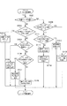
そこで、本実施形態のカメラ100は、内蔵ストロボ116をポップアップさせるためのポップアップボタン118に、内蔵ストロボ116または外部ストロボ200に関する設定画面を表示させる機能を与える。以下、この詳細について図2を参照して説明する。図2は、本発明を実施した撮像装置の実施形態であるカメラ100のストロボ設定処理を説明するフローチャートである。
Therefore, the
ユーザによるポップアップボタン118の操作に応じてストロボ設定処理が開始されると、ステップS101でCPU(第1の判定手段)111は、カメラ100に外部ストロボ200が取り付けられているか否かを判定する。具体的には、CPU111は、ストロボ制御部202に対して所定の信号を送信し、ストロボ制御部202からの返信があるか否かを判定する。すなわち、CPU111は外部ストロボ200との通信が可能であるか否かを判定する。CPU111は、外部ストロボ200との通信が可能であると判定した場合に、カメラ100に外部ストロボ200が取り付けられた状態であると判定する。また、CPU111は、外部ストロボ200との通信が可能でないと判定した場合に、カメラ100に外部ストロボ200が取り付けられていない状態であると判定する。
When the strobe setting process is started in response to the operation of the pop-up
以下、カメラ100に外部ストロボ200が取り付けられていない状態である(ステップS101でNO)と判定された場合の処理について説明する。ステップS102でCPU111は、ストロボ状態検出部(検出手段)117によって、ポップアップボタン118がオンされた際の内蔵ストロボ116の状態を検出する。具体的には、ポップアップボタン118がオンされた際に、内蔵ストロボ116の位置が収納位置(ポップダウン状態)であったか、発光位置(ポップアップ状態)であったかを検出する。
Hereinafter, a process when it is determined that the
内蔵ストロボ116がポップダウン状態である(ステップS102でYES)と判定された場合は、ステップS103でCPU(移動制御手段)111は、内蔵ストロボ116の位置を収納位置から発光位置へと移動させる。すなわち、内蔵ストロボ116をポップアップさせる。内蔵ストロボ116のポップアップが完了したら、ストロボ設定処理を終了する。
If it is determined that the built-in
内蔵ストロボ116がポップアップ状態である(ステップS102でNO)と判定された場合はステップS104に進む。ステップS104でCPU(第2の判定手段)111は、カメラ100に設定されている撮像モードが、内蔵ストロボ116および外部ストロボ200に関わる設定ができないモードであるか否かを判定する。
If it is determined that the built-in
内蔵ストロボ116および外部ストロボ200に関わる設定ができないモードとは、内蔵ストロボ116や外部ストロボ200の発光に関する設定が予め規定されている撮像モードである。例えば、撮像モードがオートモードやシーンモード、HDRモードである場合は、予め既定された発光に関する設定に基づいて内蔵ストロボ116や外部ストロボ200を発光する。この場合、ユーザの操作によって、内蔵ストロボ116や外部ストロボ200の発光に関する設定をおこなうことができない。
The mode in which settings relating to the built-in
したがって、本実施形態では、カメラ100に設定されている撮像モードがストロボの設定ができないモードに設定されている(ステップS104でYES)と判定された場合は、表示部115にエラー表示をおこなう。具体的には、ステップS105でCPU(表示制御手段)111は、図3(a)に図示するように、表示部115に内蔵ストロボ116または外部ストロボ200の設定ができない旨の画面であるエラー表示画面を表示させる。なお、図3は、本発明を実施した撮像装置の実施形態であるカメラ100の表示部に115に表示可能な画面を例示的に説明した図であって、図3(a)は、HDRモードが設定されている場合に表示される画面を例示的に説明している。この構成によって、カメラ100に設定されている撮像モードがストロボの設定ができないモードである場合に、ユーザは、内蔵ストロボ116および外部ストロボ200の設定の可否を確認することができる。
Therefore, in this embodiment, when it is determined that the imaging mode set in the
図2に戻り、設定されている撮像モードがストロボの設定ができるモードに設定されている(ステップS104でNO)と判定された場合はステップS106に進む。そして、ステップS106でCPU(第3の判定手段)111は、カメラ100の設定が、ストロボの発光が可能な設定であるか否かを判定する。具体的には、CPU111は、予めカメラ100に設定されているストロボの発光設定が「発光しない(発光無し)」に設定されているか否かを判定する。
Returning to FIG. 2, if it is determined that the set imaging mode is set to a mode capable of setting the strobe (NO in step S104), the process proceeds to step S106. In step S <b> 106, the CPU (third determination unit) 111 determines whether the setting of the
本実施形態においてユーザは、内蔵ストロボ116または外部ストロボ200の発光の可否を設定するための設定画面に基づいて、内蔵ストロボ116または外部ストロボ200の発光の可否を設定することができる。
In this embodiment, the user can set whether or not the built-in
図3(b)は、当該発光の可否を設定するための設定画面を例示的に説明する図である。図3(b)に図示するように、本実施形態では、設定項目として、内蔵ストロボ116または外部ストロボ200を発光することができる「発光する」と、内蔵ストロボ116または外部ストロボ200を発光しない「発光しない」とを設定することができる。
FIG. 3B is a diagram illustrating an example of a setting screen for setting whether or not the light emission is possible. As shown in FIG. 3B, in the present embodiment, as a setting item, “flash” that can emit the built-in
なお、図3(b)に図示するような設定項目に加えて、強制的に発光をおこなう設定項目や、測光演算の結果に応じて自動的に発光の可否を設定するような設定項目を設けるような構成であってもよい。また、内蔵ストロボ116または外部ストロボ200の発光の可否を、「強制非発光モード」や「強制発光モード」のような発光モードを選択することで設定するような構成であってもよい。
In addition to the setting items as shown in FIG. 3B, setting items for forcibly emitting light and setting items for automatically setting whether to emit light according to the result of photometric calculation are provided. Such a configuration may be adopted. Further, it may be configured such that whether the built-in
図2に戻る。ストロボの発光の可否が「発光しない」に設定されている(ステップS106でYES)と判定された場合、ステップS107でCPU(表示制御手段)111は、表示部115にストロボの発光の可否に関わる設定画面を表示させる。この構成によって、カメラ100に設定されているストロボの発光の可否が「発光しない」に設定されている場合に、ユーザは、内蔵ストロボ116および外部ストロボ200の発光の可否の再確認と再設定を簡単におこなうことができる。
Returning to FIG. If it is determined that the strobe light emission is set to “no light emission” (YES in step S106), the CPU (display control means) 111 relates to whether or not the strobe light emission is allowed on the
ストロボの発光の可否が「発光する」に設定されている(ステップS106でNO)と判定された場合、ステップS108でCPU(表示制御部)111は、表示部115に内蔵ストロボ116用の設定画面(第2の画面)を表示させる。
If it is determined that the strobe light emission is set to “light emission” (NO in step S106), the CPU (display control unit) 111 sets the setting screen for the built-in
図3(c)は、内蔵ストロボ116用の設定画面を例示的に説明する図である。図3(c)に図示するように、本実施形態では、内蔵ストロボ116用の設定画面に基づいて、発光モード、ワイヤレス設定、発光量、シンクロ設定などを設定することができる。各設定項目の詳細についての説明は省略する。なお、内蔵ストロボ116用の設定画面としては図3(c)に図示したものに限定されるものではなく、内蔵ストロボ116の設定に関する情報であれば、どのような項目を表示するような構成であってもよい。
FIG. 3C is a diagram illustrating an example of a setting screen for the built-in
表示部115に内蔵ストロボ116用の設定画面が表示された状態で、ユーザが操作部119を操作して各項目を選択すると、当該選択した項目に応じた詳細設定画面(変更画面)が表示部115に表示される。図3(d)は当該変更画面を例示的に説明する図であって、図3(c)の内蔵ストロボ116の発光モードに関する変更画面を示している。なお、設定できる発光モードの詳細な説明については省略する。
When the user operates the
図2に戻り、カメラ100に外部ストロボ200が取り付けられた状態である(ステップS101でYES)と判定された場合の処理について説明する。カメラ100に外部ストロボ200が取り付けられている状態である(ステップS101でYES)と判定された場合はステップS109に進む。ステップS109でCPU(第2の判定手段)111は、カメラ100に設定されている撮像モードが、内蔵ストロボ116および外部ストロボ200に関わる設定ができない撮像モードであるか否かを判定する。以降のステップS110〜S112の処理は、前述したステップS105〜S107と同様なので説明は省略する。
Returning to FIG. 2, processing when it is determined that the
ステップS113でCPU111は、ストロボ制御部202から外部ストロボ200に関する情報を受信する。この外部ストロボ200に関する情報とは、図3(c)に図示したような各項目に関する情報の他に、内蔵ストロボ116では設定できない情報を含んでいる。この情報としては、例えば、外部ストロボ200を発光する際の光の照射角度などに関する情報である。受信した外部ストロボ200に関する情報はメモリ109に記録される。
In step S <b> 113, the
なお、外部ストロボ200に関する情報は、ステップS113の処理がおこなわれる際に外部ストロボ200に設定されている情報であって、当該情報は、外部ストロボ用の操作部を操作することによって事前に設定されたものである。また、外部ストロボ200の動作状態がスリープ状態である場合は、CPU111は、外部ストロボ200の動作状態を起動状態へと変更した後に、外部ストロボ200に関する情報を取得する。なお、スリープ状態とは、外部ストロボ200の動作状態が起動状態である場合よりも電力の消費が少ない状態であって、外部ストロボ200において所定の動作が停止させた状態である。
The information regarding the
次に、ステップS114でCPU(表示制御部)111は、先に受信した外部ストロボ200に関する情報をメモリ109から読み出し、当該情報に基づいて、表示部115に外部ストロボ200用の設定画面(第1の画面)を表示させる。
Next, in step S114, the CPU (display control unit) 111 reads the information about the
図3(e)は、外部ストロボ200用の設定画面を例示的に説明する図である。図3(e)に図示するように、本実施形態の外部ストロボ200用の設定画面は、内蔵ストロボ116用の設定画面に加えて、前述した外部ストロボ200を発光する際の光の照射角度を設定する項目などを加えた画面である。すなわち、外部ストロボ200用の設定画面は、基本的には内蔵ストロボ116用の設定画面と共通であって、外部ストロボ200のみで設定可能な設定項目が加えられた設定画面である。
FIG. 3E is a diagram for exemplarily explaining a setting screen for the
なお、本実施形態では、内蔵ストロボ116用の設定画面の設定項目に外部ストロボ200を使用する場合のみで設定可能な項目を表示しないような構成であるが、これに限定されるものではない。例えば、外部ストロボ200を使用する場合の実に設定可能な項目と内蔵ストロボ116用の設定画面に表示させ、当該設定項目をグレーアウトさせておくような構成であってもよい。以上が、本実施形態のストロボ設定処理の説明である。
In the present embodiment, the setting items on the setting screen for the built-in
以上説明したように、本実施形態のカメラ100は、ポップアップボタン118を用いて内蔵ストロボ116または外部ストロボ200に関する設定画面を表示部115に表示することができる。そして、ポップアップボタン118が操作された際に、カメラ100に外部ストロボ200が取り付けられているか否かに応じて、表示部115に内蔵ストロボ116用または外部ストロボ200用の設定画面のどちらを表示させるかを切り換えることができる。この構成によって、ユーザは、内蔵ストロボ116や外部ストロボ200に関わる設定の変更を意図した際に、他の設定項目を設定するための設定画面を経由することなく、ストロボの設定画面を表示部115に表示することができる。また、ユーザは、複数の階層に分かれた複数のストロボの設定画面の中から、ユーザが意図する設定画面を、表示部115に簡単に表示することができる。したがって、本実施形態のカメラ100は、ユーザによる煩雑な操作を必要とせずに、発光手段の設定に関する画面を表示することができる。
As described above, the
また、本実施形態では、外部ストロボ200がカメラ100に取り付けられていない状態であって内蔵ストロボ116がポップアップしている状態でポップアップボタン118を操作すると、内蔵ストロボ116用の設定画面を表示部115に表示できる。そして、内蔵ストロボ116がポップダウンしている状態でポップアップボタン118を操作すると、内蔵ストロボ116が発光位置にポップアップすることができる。
In this embodiment, when the pop-up
このように、本実施形態では、ポップアップボタン118を操作した際の内蔵ストロボ116の位置に応じて、内蔵ストロボ116用の設定画面を表示させるか、内蔵ストロボ116をポップアップさせるかを切り換えている。この構成によって、本実施形態のカメラ100では、内蔵ストロボ116用の設定画面を表示させるための操作部を新たに設けることなく、当該設定画面を表示部115に表示させることができる。
As described above, in this embodiment, the setting screen for the built-in
また、本実施形態では、外部ストロボ200を取り付てることが可能なカメラ100の構成について説明したが、これに限定されるものではなく、例えば、カメラ100が外部ストロボ200を取り付けることができない構成であってもよい。この場合、前述したステップS101、S109〜S114の処理をおこなわないような構成であればよい。
In the present embodiment, the configuration of the
さらに、本実施形態では、カメラ100に設定されている撮像モードや、ストロボの発光の可否に応じて、ストロボ設定ができない旨を通知するエラー表示画面や、ストロボの発光有無を設定するための設定画面を表示部115に表示させることができる。この構成によって、ユーザは、煩雑な操作を必要とせずに、内蔵ストロボ116や外部ストロボ200に関する現在の設定の確認と当該設定の変更をおこなうことができる。
Furthermore, in the present embodiment, an error display screen for notifying that the strobe cannot be set according to the imaging mode set in the
以上説明したように、本実施形態のカメラ100は、内蔵ストロボ116の位置、外部ストロボ200の取り付けの有無、撮像モード、ストロボの発光の可否などの条件に応じて、表示部115に表示させる設定画面を切り換えることができる。これらの構成によって、本実施形態のカメラ100は、ユーザの意図に対する、内蔵ストロボ116および外部ストロボ200に関する設定の操作性を向上させることができる。
As described above, the
以上、本発明の好ましい実施形態について説明したが、本発明はこれらの実施形態に限定されず、その要旨の範囲内で種々の変形及び変更が可能である。本実施形態の内蔵ストロボ116はポップアップ可能なものを採用した場合について説明したが、これに限定されるものではない。例えば、カメラ100の所定の位置で回動可能な内蔵ストロボを採用するような構成であってもよい。この場合、カメラ100から発光部が露出する内蔵ストロボの位置が発光位置に該当し、発光部が隠れる内蔵ストロボの位置が収納位置に該当する。
As mentioned above, although preferable embodiment of this invention was described, this invention is not limited to these embodiment, A various deformation | transformation and change are possible within the range of the summary. Although the case where the built-in
また、本実施形態では、内蔵ストロボ116用の設定画面と外部ストロボ200用の設定画面、ストロボの発光有無を設定する画面とがそれぞれ異なるような構成について説明したが、これに限定されるものではない。例えば、上述したそれぞれの設定画面が同一であってもよい。
In this embodiment, the configuration in which the setting screen for the built-in
また、前述した実施形態では、カメラ100の内部に設けられた制御部や処理部などが互いに連携して動作することによって、カメラ100の動作を制御するような構成であるが、これに限定されるものではない。前述した図2のフローに従ったプログラムを予めメモリ109に格納しておき、当該プログラムをCPU111が実行することで、カメラ100の動作を制御するような構成であってもよい。
In the above-described embodiment, the configuration is such that the control unit and the processing unit provided in the
また、プログラムの機能を有していれば、オブジェクトコード、インタプリタにより実行されるプログラム、OSに供給するスクリプトデータ等、プログラムの形態を問わない。また、プログラムを供給するための記録媒体としては、例えば、ハードディスク、磁気テープ等の磁気記録媒体、光/光磁気記録媒体でもあってもよい。 Moreover, as long as it has the function of a program, it does not ask | require the form of programs, such as an object code, the program run by an interpreter, and the script data supplied to OS. The recording medium for supplying the program may be, for example, a magnetic recording medium such as a hard disk or a magnetic tape, or an optical / magneto-optical recording medium.
(その他の実施形態)
また、本発明は、以下の処理を実行することによっても実現される。すなわち、上述した実施形態の機能を実現するソフトウェア(プログラム)を、ネットワークまたは各種記録媒体を介してシステム或いは装置に供給する。そして、そのシステム或いは装置のコンピュータ(またはCPUやMPU等)がプログラムを読み出して実行する処理である。
(Other embodiments)
The present invention can also be realized by executing the following processing. That is, software (program) that realizes the functions of the above-described embodiments is supplied to a system or apparatus via a network or various recording media. Then, the computer (or CPU, MPU, etc.) of the system or apparatus reads out and executes the program.
100 デジタルカメラ(撮像装置)
111 カメラ制御部(第1の判定手段、表示制御手段、移動制御手段)
116 内蔵ストロボ(第2の発光手段)
117 ストロボ状態検出部(検出手段)
118 ポップアップボタン(操作部)
200 外部ストロボ(発光装置)
207 発光部(第1の発光手段)
100 Digital camera (imaging device)
111 Camera control unit (first determination means, display control means, movement control means)
116 Built-in strobe (second light emitting means)
117 Strobe state detection unit (detection means)
118 Pop-up button (operation unit)
200 External strobe (light emitting device)
207 Light emitting unit (first light emitting means)
Claims (11)
発光位置と収納位置とを移動できる第2の発光手段と、
ユーザによって操作されることで、前記第2の発光手段を移動させることができる操作部と、
前記操作部が操作された際に前記発光装置が前記撮像装置に取り付けられているか、否かを判定する第1の判定手段と、
前記第1の発光手段の設定に関する第1の画面、または前記第2の発光手段の設定に関する第2の画面を表示手段に表示させる制御をおこなう表示制御手段と、
を有し、
前記表示制御手段は、前記第1の判定手段によって前記発光装置が前記撮像装置に取り付けられていると判定された場合に前記操作部が操作されたことに応じて前記第1の画面を前記表示手段に表示させることを特徴とする撮像装置。 An imaging apparatus to which a light emitting device including a first light emitting means can be attached,
A second light emitting means capable of moving between the light emitting position and the storage position;
An operation unit capable of moving the second light emitting means by being operated by a user;
First determination means for determining whether or not the light emitting device is attached to the imaging device when the operation unit is operated;
Display control means for controlling the display means to display a first screen relating to the setting of the first light emitting means or a second screen relating to the setting of the second light emitting means;
Have
The display control unit displays the first screen in response to an operation of the operation unit when the first determination unit determines that the light emitting device is attached to the imaging device. An image pickup apparatus characterized by being displayed on a means.
前記表示制御手段は、前記第1の判定手段によって前記発光装置が前記撮像装置に取り付けられていないと判定された場合であって、前記検出手段によって前記第2の発光手段が前記発光位置に位置していることを検出した場合に前記操作部が操作されたことに応じて前記表示手段に前記第2の画面を表示させることを特徴とする請求項1に記載の撮像装置。 Detecting means for detecting a position of the second light emitting means when the operation unit is operated;
The display control means is a case where the first determination means determines that the light emitting device is not attached to the imaging device, and the detection means positions the second light emission means at the light emission position. The imaging apparatus according to claim 1, wherein when the operation unit is detected, the display unit displays the second screen in response to an operation of the operation unit.
前記表示制御手段は、前記第2の判定手段によって前記第1の発光手段および前記第2の発光手段の設定ができないモードが設定されていると判定された場合に、前記操作部が操作されたことに応じて前記表示手段に前記第1の発光手段または前記第2の発光手段の設定ができない旨の画面を表示させる制御をおこなうことを特徴とする請求項1又は2に記載の撮像装置。 A second determination unit that determines whether or not a mode in which the first light emitting unit and the second light emitting unit cannot be set when the operation unit is operated;
The display control means operates the operation unit when the second determination means determines that a mode in which the first light emission means and the second light emission means cannot be set is set. 3. The image pickup apparatus according to claim 1, wherein control is performed to display a screen indicating that the first light emitting unit or the second light emitting unit cannot be set on the display unit.
前記表示制御手段は、前記第3の判定手段によって前記第1の発光手段および前記第2の発光手段の発光が可能な設定であると判定された場合に、前記操作部が操作されたことに応じて前記発光の可否を設定するための画面を表示することを特徴とする請求項1乃至3の何れか一項に記載の撮像装置。 A third determination unit that determines whether or not the first light emitting unit and the second light emitting unit can emit light when the operation unit is operated;
When the display control means determines that the first light emitting means and the second light emitting means are set to emit light by the third determining means, the operation unit is operated. 4. The image pickup apparatus according to claim 1, wherein a screen for setting whether or not to emit light is displayed in response. 5.
ユーザによって操作されることで、前記発光手段を移動させることができる操作部と、
前記操作部が操作された際の前記発光手段の位置を検出する検出手段と、
前記発光手段の設定に関する画面を表示手段に表示させる制御をおこなう表示制御手段と、
前記発光手段を前記収納位置から前記発光位置に移動させる制御をおこなう移動制御手段と、
を有し、
前記表示制御手段は、前記検出手段によって前記発光手段が前記発光位置に位置すると検出された場合に前記操作部が操作されたことに応じて前記発光手段の設定に関する画面を前記表示手段に表示させる制御をおこない、
前記移動制御手段は、前記検出手段によって前記発光手段が前記収納位置に位置すると検出された場合に前記操作部が操作されたことに応じて前記発光手段を前記発光位置へと移動させる制御をおこなうことを特徴とする撮像装置。 A light emitting means capable of moving between the light emitting position and the storage position;
An operation unit capable of moving the light emitting means by being operated by a user;
Detecting means for detecting a position of the light emitting means when the operation unit is operated;
Display control means for controlling the display means to display a screen relating to the setting of the light emitting means;
Movement control means for performing control to move the light emitting means from the storage position to the light emitting position;
Have
The display control means causes the display means to display a screen relating to the setting of the light emitting means in response to the operation unit being operated when the detecting means detects that the light emitting means is located at the light emitting position. Control,
The movement control means performs control to move the light emission means to the light emission position in response to the operation unit being operated when the detection means detects that the light emission means is located at the storage position. An imaging apparatus characterized by that.
前記操作部が操作された際に前記発光装置が前記撮像装置に取り付けられているか、否かを判定する第1の判定工程と、
前記第1の発光手段の設定に関する第1の画面、または前記第2の発光手段の設定に関する第2の画面を表示手段に表示させる制御をおこなう表示制御工程と、
を有し、
前記表示制御工程は、前記第1の判定工程によって前記発光装置が前記撮像装置に取り付けられていると判定された場合に前記操作部が操作されたことに応じて前記第1の画面を前記表示手段に表示させることを特徴とする撮像装置の制御方法。 A light emitting device comprising: a second light emitting unit capable of moving between a light emitting position and a storage position; and an operation unit capable of moving the second light emitting unit by being operated by a user, and the first light emitting unit. A method of controlling an imaging apparatus to which can be attached,
A first determination step of determining whether or not the light emitting device is attached to the imaging device when the operation unit is operated;
A display control step for performing control to display on the display means a first screen relating to the setting of the first light emitting means or a second screen relating to the setting of the second light emitting means;
Have
The display control step displays the first screen in response to an operation of the operation unit when it is determined in the first determination step that the light emitting device is attached to the imaging device. A control method for an image pickup apparatus, characterized in that the image display apparatus displays the image on a means.
前記操作部が操作をされた際の前記発光手段の位置を検出する検出工程と、
前記発光手段の設定に関する画面を表示手段に表示させる制御をおこなう表示制御工程と、
前記発光手段を前記収納位置から前記発光位置に移動させる制御をおこなう移動制御工程と、
を有し、
前記表示制御工程は、前記検出工程によって前記発光手段が前記発光位置に位置すると検出された場合に前記操作部が操作されたことに応じて前記発光手段の設定に関する画面を前記表示手段に表示させる制御をおこない、
前記移動制御工程は、前記検出工程によって前記発光手段が前記収納位置に位置すると検出された場合に前記操作部が操作されたことに応じて前記発光手段を前記発光位置へと移動させる制御をおこなうことを特徴とする撮像装置の制御方法。 An imaging apparatus comprising: a light emitting means capable of moving between a light emitting position and a storage position; and an operation unit capable of moving the light emitting means when operated by a user,
A detection step of detecting a position of the light emitting means when the operation unit is operated;
A display control step for performing control for displaying on the display means a screen relating to the setting of the light emitting means;
A movement control step for performing control to move the light emitting means from the storage position to the light emitting position;
Have
In the display control step, when the detection unit detects that the light emitting unit is located at the light emitting position, the display unit displays a screen relating to the setting of the light emitting unit in response to the operation unit being operated. Control,
The movement control step performs control to move the light emitting unit to the light emitting position in response to the operation unit being operated when it is detected by the detecting step that the light emitting unit is located at the storage position. And a method of controlling the imaging apparatus.
Priority Applications (4)
| Application Number | Priority Date | Filing Date | Title |
|---|---|---|---|
| JP2014128587A JP6632184B2 (en) | 2014-06-23 | 2014-06-23 | Imaging device, control method, and program |
| CN201510346797.5A CN105306812A (en) | 2014-06-23 | 2015-06-19 | Image pickup apparatus and control method |
| US14/745,280 US9838582B2 (en) | 2014-06-23 | 2015-06-19 | Image pickup apparatus and control method for displaying a screen related to a setting of a light emission |
| US15/785,242 US20180041676A1 (en) | 2014-06-23 | 2017-10-16 | Image pickup apparatus and control method |
Applications Claiming Priority (1)
| Application Number | Priority Date | Filing Date | Title |
|---|---|---|---|
| JP2014128587A JP6632184B2 (en) | 2014-06-23 | 2014-06-23 | Imaging device, control method, and program |
Publications (3)
| Publication Number | Publication Date |
|---|---|
| JP2016009032A true JP2016009032A (en) | 2016-01-18 |
| JP2016009032A5 JP2016009032A5 (en) | 2017-08-03 |
| JP6632184B2 JP6632184B2 (en) | 2020-01-22 |
Family
ID=54870814
Family Applications (1)
| Application Number | Title | Priority Date | Filing Date |
|---|---|---|---|
| JP2014128587A Expired - Fee Related JP6632184B2 (en) | 2014-06-23 | 2014-06-23 | Imaging device, control method, and program |
Country Status (3)
| Country | Link |
|---|---|
| US (2) | US9838582B2 (en) |
| JP (1) | JP6632184B2 (en) |
| CN (1) | CN105306812A (en) |
Cited By (1)
| Publication number | Priority date | Publication date | Assignee | Title |
|---|---|---|---|---|
| WO2021124883A1 (en) * | 2019-12-16 | 2021-06-24 | ソニーグループ株式会社 | Photographing system, control method, and program |
Families Citing this family (4)
| Publication number | Priority date | Publication date | Assignee | Title |
|---|---|---|---|---|
| JP6971794B2 (en) * | 2017-11-14 | 2021-11-24 | キヤノン株式会社 | Lighting equipment and its control method |
| CN108810380B (en) * | 2018-06-29 | 2020-09-29 | 维沃移动通信有限公司 | Terminal equipment and control method |
| CN108965728B (en) * | 2018-07-06 | 2021-05-18 | 维沃移动通信有限公司 | Brightness adjusting method and terminal |
| JP7258631B2 (en) | 2019-04-04 | 2023-04-17 | キヤノン株式会社 | IMAGING DEVICE, ACCESSORY DEVICE, AND CONTROL METHOD THEREOF |
Citations (3)
| Publication number | Priority date | Publication date | Assignee | Title |
|---|---|---|---|---|
| JP2002072303A (en) * | 2000-08-25 | 2002-03-12 | Nikon Corp | Camera provided with photographic information setting device |
| JP2006163243A (en) * | 2004-12-10 | 2006-06-22 | Sony Corp | Imaging device and control method thereof |
| JP2008116748A (en) * | 2006-11-06 | 2008-05-22 | Nikon Corp | Camera system and camera |
Family Cites Families (10)
| Publication number | Priority date | Publication date | Assignee | Title |
|---|---|---|---|---|
| US6154210A (en) * | 1998-11-25 | 2000-11-28 | Flashpoint Technology, Inc. | Method and system for implementing button interface compatibility in touch-screen equipped digital imaging device |
| US6738075B1 (en) * | 1998-12-31 | 2004-05-18 | Flashpoint Technology, Inc. | Method and apparatus for creating an interactive slide show in a digital imaging device |
| US6909847B2 (en) * | 2002-10-09 | 2005-06-21 | Matsushita Electric Industrial Co., Ltd. | Camera with built-in strobe |
| JP4415184B2 (en) | 2004-03-08 | 2010-02-17 | カシオ計算機株式会社 | Imaging apparatus and light emission control method |
| US7546555B2 (en) * | 2006-02-24 | 2009-06-09 | Sony Ericsson Mobile Communications Ab | Method and apparatus for matching a control with an icon |
| US7813629B2 (en) * | 2007-07-23 | 2010-10-12 | Fujifilm Corporation | Photographing apparatus, and control method and computer program product for controlling the same |
| JP2010226186A (en) * | 2009-03-19 | 2010-10-07 | Olympus Imaging Corp | Imaging apparatus, and method of controlling imaging apparatus |
| US20110185313A1 (en) * | 2010-01-26 | 2011-07-28 | Idan Harpaz | Method and system for customizing a user-interface of an end-user device |
| JP5526101B2 (en) * | 2010-11-02 | 2014-06-18 | パナソニック株式会社 | Imaging device |
| JP5691829B2 (en) * | 2011-05-17 | 2015-04-01 | リコーイメージング株式会社 | Built-in flash pop-up mechanism of the camera |
-
2014
- 2014-06-23 JP JP2014128587A patent/JP6632184B2/en not_active Expired - Fee Related
-
2015
- 2015-06-19 US US14/745,280 patent/US9838582B2/en active Active
- 2015-06-19 CN CN201510346797.5A patent/CN105306812A/en active Pending
-
2017
- 2017-10-16 US US15/785,242 patent/US20180041676A1/en not_active Abandoned
Patent Citations (3)
| Publication number | Priority date | Publication date | Assignee | Title |
|---|---|---|---|---|
| JP2002072303A (en) * | 2000-08-25 | 2002-03-12 | Nikon Corp | Camera provided with photographic information setting device |
| JP2006163243A (en) * | 2004-12-10 | 2006-06-22 | Sony Corp | Imaging device and control method thereof |
| JP2008116748A (en) * | 2006-11-06 | 2008-05-22 | Nikon Corp | Camera system and camera |
Cited By (1)
| Publication number | Priority date | Publication date | Assignee | Title |
|---|---|---|---|---|
| WO2021124883A1 (en) * | 2019-12-16 | 2021-06-24 | ソニーグループ株式会社 | Photographing system, control method, and program |
Also Published As
| Publication number | Publication date |
|---|---|
| US20180041676A1 (en) | 2018-02-08 |
| US9838582B2 (en) | 2017-12-05 |
| US20150373242A1 (en) | 2015-12-24 |
| CN105306812A (en) | 2016-02-03 |
| JP6632184B2 (en) | 2020-01-22 |
Similar Documents
| Publication | Publication Date | Title |
|---|---|---|
| TWI608734B (en) | Image pickup apparatus, electronic device, control method, and camera system | |
| US8462254B2 (en) | Image pickup apparatus capable of setting a photographic condition and control method therefor | |
| KR100932462B1 (en) | Imaging device | |
| US9625973B2 (en) | Electronic apparatus with display unit, and display control method for electronic apparatus with display unit | |
| US20180041676A1 (en) | Image pickup apparatus and control method | |
| JP2006352723A (en) | Imaging apparatus, imaging system and synchronizing method | |
| JP2007028211A (en) | Imaging apparatus and control method thereof | |
| US20160373635A1 (en) | Image capturing apparatus, method for controlling the same, and storage medium | |
| JP2012204953A (en) | Imaging system, illumination device, and camera | |
| US9560286B2 (en) | Image capturing apparatus and method for controlling the same | |
| JP2013015722A (en) | Imaging apparatus and method and program for controlling the same | |
| JP2016143951A (en) | Image processing apparatus, imaging device, image processing method and image processing program | |
| JP2009288657A (en) | Stroboscopic photographing device | |
| JP2006119264A (en) | Photographing equipment | |
| JP5791254B2 (en) | Imaging apparatus and camera system | |
| US8306411B2 (en) | Photographic apparatus | |
| JP2009031462A (en) | Imaging apparatus | |
| JP5959957B2 (en) | Imaging apparatus and control method thereof | |
| JP6452310B2 (en) | Imaging apparatus, control method, and program | |
| JP6335497B2 (en) | Imaging device, control method thereof, and control program | |
| JP2007086181A (en) | Imaging apparatus, imaging method and program | |
| JP6344910B2 (en) | Imaging apparatus, control method, and program thereof | |
| JP2010107900A (en) | Imaging apparatus, compound eye imaging apparatus, imaging method and program | |
| JP2020071446A (en) | Imaging device, imaging system, light-emitting device, and light emission control method for imaging device | |
| JP2015103943A (en) | Imaging apparatus, control method of the same, and control program |
Legal Events
| Date | Code | Title | Description |
|---|---|---|---|
| A521 | Request for written amendment filed |
Free format text: JAPANESE INTERMEDIATE CODE: A523 Effective date: 20170622 |
|
| A621 | Written request for application examination |
Free format text: JAPANESE INTERMEDIATE CODE: A621 Effective date: 20170622 |
|
| A977 | Report on retrieval |
Free format text: JAPANESE INTERMEDIATE CODE: A971007 Effective date: 20180328 |
|
| A131 | Notification of reasons for refusal |
Free format text: JAPANESE INTERMEDIATE CODE: A131 Effective date: 20180403 |
|
| A521 | Request for written amendment filed |
Free format text: JAPANESE INTERMEDIATE CODE: A523 Effective date: 20180528 |
|
| A131 | Notification of reasons for refusal |
Free format text: JAPANESE INTERMEDIATE CODE: A131 Effective date: 20181113 |
|
| A521 | Request for written amendment filed |
Free format text: JAPANESE INTERMEDIATE CODE: A523 Effective date: 20181227 |
|
| A131 | Notification of reasons for refusal |
Free format text: JAPANESE INTERMEDIATE CODE: A131 Effective date: 20190528 |
|
| A521 | Request for written amendment filed |
Free format text: JAPANESE INTERMEDIATE CODE: A523 Effective date: 20190724 |
|
| TRDD | Decision of grant or rejection written | ||
| A01 | Written decision to grant a patent or to grant a registration (utility model) |
Free format text: JAPANESE INTERMEDIATE CODE: A01 Effective date: 20191112 |
|
| A61 | First payment of annual fees (during grant procedure) |
Free format text: JAPANESE INTERMEDIATE CODE: A61 Effective date: 20191210 |
|
| R151 | Written notification of patent or utility model registration |
Ref document number: 6632184 Country of ref document: JP Free format text: JAPANESE INTERMEDIATE CODE: R151 |
|
| LAPS | Cancellation because of no payment of annual fees |