JP2016006468A - Image forming apparatus - Google Patents
Image forming apparatus Download PDFInfo
- Publication number
- JP2016006468A JP2016006468A JP2014127426A JP2014127426A JP2016006468A JP 2016006468 A JP2016006468 A JP 2016006468A JP 2014127426 A JP2014127426 A JP 2014127426A JP 2014127426 A JP2014127426 A JP 2014127426A JP 2016006468 A JP2016006468 A JP 2016006468A
- Authority
- JP
- Japan
- Prior art keywords
- image forming
- toner
- unit
- developer
- forming apparatus
- Prior art date
- Legal status (The legal status is an assumption and is not a legal conclusion. Google has not performed a legal analysis and makes no representation as to the accuracy of the status listed.)
- Granted
Links
- 238000001514 detection method Methods 0.000 claims abstract description 44
- 238000012790 confirmation Methods 0.000 claims description 14
- 238000012546 transfer Methods 0.000 description 48
- 230000005856 abnormality Effects 0.000 description 45
- 238000000034 method Methods 0.000 description 28
- 230000008569 process Effects 0.000 description 28
- 230000032258 transport Effects 0.000 description 10
- 238000012545 processing Methods 0.000 description 9
- 238000003756 stirring Methods 0.000 description 9
- 238000004140 cleaning Methods 0.000 description 7
- 238000003780 insertion Methods 0.000 description 7
- 230000037431 insertion Effects 0.000 description 7
- 238000011144 upstream manufacturing Methods 0.000 description 7
- 230000005540 biological transmission Effects 0.000 description 6
- 238000010438 heat treatment Methods 0.000 description 6
- 230000007246 mechanism Effects 0.000 description 6
- 238000007639 printing Methods 0.000 description 5
- 230000000052 comparative effect Effects 0.000 description 4
- 238000010586 diagram Methods 0.000 description 4
- 238000004891 communication Methods 0.000 description 3
- 230000003247 decreasing effect Effects 0.000 description 3
- 238000000926 separation method Methods 0.000 description 3
- 230000002159 abnormal effect Effects 0.000 description 2
- 238000013019 agitation Methods 0.000 description 2
- 230000001186 cumulative effect Effects 0.000 description 2
- 230000000694 effects Effects 0.000 description 2
- 230000006870 function Effects 0.000 description 2
- 230000003287 optical effect Effects 0.000 description 2
- 238000003825 pressing Methods 0.000 description 2
- 230000004044 response Effects 0.000 description 2
- 239000002699 waste material Substances 0.000 description 2
- BQCADISMDOOEFD-UHFFFAOYSA-N Silver Chemical compound [Ag] BQCADISMDOOEFD-UHFFFAOYSA-N 0.000 description 1
- 238000012937 correction Methods 0.000 description 1
- 238000011161 development Methods 0.000 description 1
- 238000005516 engineering process Methods 0.000 description 1
- 239000000284 extract Substances 0.000 description 1
- PCHJSUWPFVWCPO-UHFFFAOYSA-N gold Chemical compound [Au] PCHJSUWPFVWCPO-UHFFFAOYSA-N 0.000 description 1
- 229910052737 gold Inorganic materials 0.000 description 1
- 239000010931 gold Substances 0.000 description 1
- 229910052736 halogen Inorganic materials 0.000 description 1
- 150000002367 halogens Chemical class 0.000 description 1
- 239000004973 liquid crystal related substance Substances 0.000 description 1
- 230000007257 malfunction Effects 0.000 description 1
- 239000010445 mica Substances 0.000 description 1
- 229910052618 mica group Inorganic materials 0.000 description 1
- 238000012544 monitoring process Methods 0.000 description 1
- 230000002093 peripheral effect Effects 0.000 description 1
- 230000010363 phase shift Effects 0.000 description 1
- 229910052709 silver Inorganic materials 0.000 description 1
- 239000004332 silver Substances 0.000 description 1
Images


Abstract
Description
本発明は、現像剤を用いて画像を形成する画像形成装置に関する。 The present invention relates to an image forming apparatus that forms an image using a developer.
従来の画像形成装置は、着脱可能に取り付けられる画像形成部を有し、その画像形成部に現像剤を供給する現像剤収容部を着脱可能に備えているものがある(例えば、特許文献1参照)。 Some conventional image forming apparatuses include an image forming unit that is detachably attached, and is detachably provided with a developer storage unit that supplies developer to the image forming unit (see, for example, Patent Document 1). ).
しかしながら、従来の技術においては、現像剤収容部の画像形成部への装着不備があった場合、現像剤が正常に供給されないことがあるという問題がある。
本発明は、このような問題を解決することを課題とし、現像剤が正常に供給されないことを抑制することを目的とする。
However, the conventional technology has a problem in that the developer may not be supplied normally when the developer accommodating portion is not properly attached to the image forming portion.
An object of the present invention is to solve such a problem, and an object of the present invention is to prevent the developer from being supplied normally.
そのため、本発明は、情報を表示する表示部と、画像形成部と、前記画像形成部内の所定位置で現像剤を検出する検出部と、前記画像形成部に対して着脱可能に設けられた現像剤収容部と、前記現像剤収容部の使用状態を表す値を記憶する記憶部と、前記現像剤収容部から前記画像形成部に現像剤を供給する現像剤供給部と、前記現像剤供給部を制御する制御部と、を有し、前記制御部は、前記検出部の検出結果と前記使用状態を表す値とに基づいて、前記表示部に、着脱可能な前記現像剤収容部への対応を促す表示を行うことを特徴とする。 Therefore, the present invention provides a display unit that displays information, an image forming unit, a detection unit that detects a developer at a predetermined position in the image forming unit, and a development that is detachably attached to the image forming unit. A developer storage unit, a storage unit that stores a value indicating a use state of the developer storage unit, a developer supply unit that supplies the developer from the developer storage unit to the image forming unit, and the developer supply unit A control unit that controls the developer storage unit detachably attached to the display unit based on a detection result of the detection unit and a value indicating the use state. It is characterized by performing a display prompting the user.
このようにした本発明は、現像剤が正常に供給されないことを抑制することができるという効果が得られる。 According to the present invention thus configured, it is possible to prevent the developer from being supplied normally.
以下、図面を参照して本発明による画像形成装置の実施例を説明する。 Embodiments of an image forming apparatus according to the present invention will be described below with reference to the drawings.
図2は第1の実施例における画像形成装置の構成を示す概略側断面図である。
図2において、画像形成装置101は、画像形成部としての感光体ドラムユニット102K(K:ブラック色)、102C(C:シアン色)、102M(M:マゼンタ色)、102Y(Y:イエロー色)を備えている。この感光体ドラムユニット102K、102C、102M、102Yは、同様の構成なので感光体ドラムユニット102Kを代表として説明する。なお、以下の説明では、Kの記号を省略して説明するものとする。
FIG. 2 is a schematic sectional side view showing the configuration of the image forming apparatus in the first embodiment.
In FIG. 2, an
感光体ドラムユニット102は、画像形成装置101に対して着脱可能に取り付けられ、帯電ローラ104と、供給ローラ105と、現像ローラ106と、現像ブレード107と、感光体ドラム108と、感光体ドラムクリーニングブレード109とにより構成されている。
また、現像剤としてのトナーを収容する現像剤収容部としてのトナーカートリッジ110は、画像形成装置101および感光体ドラムユニット102に対して着脱可能に設けられ、現像剤供給路としてのトナーダクト111を介してトナーカートリッジ110と感光体ドラムユニット102とが接続されている。
The
In addition, a
トナーダクト111は、画像形成装置101本体に取り付けられており、画像形成装置101本体に対して着脱可能なトナーカートリッジ110と感光体ドラムユニット102とを繋ぎ、トナーカートリッジ110内から感光体ドラムユニット102へ供給されるトナーの通路(供給路)となるものである。
なお、感光体ドラムユニット102およびトナーカートリッジ110を総称して「消耗品」という。
The
The
感光体ドラム108は、図中矢印Aが示す方向に回転し、当接する帯電ローラ104によって一様に帯電される。
帯電された感光体ドラム108は、対向して配設されたLED(Light Emitting Diode)ヘッド103の発光によって静電潜像が形成される。供給ローラ105は、現像ローラ106に現像剤としてのトナーを供給し、現像ブレード107により、現像ローラ106の表面に一様にトナー層が形成される。
現像ローラ106の表面のトナーが感光体ドラム108の静電潜像に搬送され、感光体ドラム108の表面にトナー像が現像される。
The photosensitive drum 108 rotates in the direction indicated by the arrow A in the figure, and is uniformly charged by the charging roller 104 in contact therewith.
On the charged photosensitive drum 108, an electrostatic latent image is formed by light emission of an LED (Light Emitting Diode) head 103 disposed so as to face the photosensitive drum 108. The supply roller 105 supplies toner as a developer to the developing
The toner on the surface of the developing
感光体ドラムクリーニングブレード109は、感光体ドラム108の表面のトナー像が媒体に転写された後の感光体ドラム108の表面の残トナーを掻き取るクリーニング機構である。
また、画像形成装置101は、一次転写ローラ112と、中間転写ベルト113と、転写ベルト駆動ローラ114と、転写ベルト従動ローラ115、116、117と、バックアップローラ118と、中間転写ベルトクリーニングブレード119と、廃トナーボックス120とを備えている。
The photosensitive drum cleaning blade 109 is a cleaning mechanism that scrapes off residual toner on the surface of the photosensitive drum 108 after the toner image on the surface of the photosensitive drum 108 is transferred to the medium.
The
一次転写ローラ112は、中間転写ベルト113を介して感光体ドラム108と対向するように配設され、無端状の中間転写ベルト113の内周面から感光体ドラム108と対向する転写位置にバイアス電圧を印加することができるように配設されている。
転写ベルト駆動ローラ114と、転写ベルト従動ローラ115、116、117と、バックアップローラ118とは、中間転写ベルト113を張架し、転写ベルト駆動ローラ114の駆動により中間転写ベルト113を図中矢印Bが示す方向(中間転写ベルト113の移動方向)へ回転させる。
The primary transfer roller 112 is disposed so as to face the photosensitive drum 108 with the
The transfer
図中矢印Bが示す中間転写ベルト113の回転方向における上流側から感光体ドラムユニット102Y、102M、102C、102Kが順に配置され、それぞれの感光体ドラム108に形成されたトナー像が一次転写ローラ112により中間転写ベルト113上に一次転写される。
バックアップローラ118には、中間転写ベルト113から媒体が離れる向きのバイアス電圧が印加される。
中間転写ベルトクリーニングブレード119は、転写ベルト113上の転写残トナー等のトナーが掻き落せるようになっており、廃トナーボックス120には掻き落されたトナーが収容される。
The
A bias voltage is applied to the
The intermediate transfer
さらに、画像形成装置101は、用紙トレイ121と、ピックアップローラ122と、給紙ローラ123と、分離ローラ124と、給紙センサ125と、レジストローラ対126と、搬送ローラ対127、128、134と、書き出しセンサ129と、二次転写ローラ130と、定着ユニット131と、加熱加圧手段132、133と、排出ローラ対135と、排出トレイ136とを備えている。
用紙トレイ121は、画像形成装置101に着脱可能に取り付けられ、媒体としての用紙Pを積載して収容する。
Further, the
The
ピックアップローラ122は、用紙Pを用紙トレイ121から取り出し、図中矢印Cが示す用紙搬送方向へ搬送し給紙ローラ123に受け渡す。分離ローラ124は、給紙ローラ123に対向配置され、用紙Pの搬送方向とは逆向きの力を用紙Pに加えることにより用紙トレイ121から用紙Pを1枚ずつ取り出せるようにする。
給紙センサ125は、用紙Pの搬送路において給紙搬送ローラ123により搬送される用紙Pの有無を検出するセンサである。
レジストローラ対126は、停止した状態で用紙Pを突き当て、用紙Pの斜行(スキュー)を補正する。
The
The
The
搬送ローラ対127、128は、レジストローラ対126により搬送された用紙Pをバックアップローラ118と二次転写ローラ130とにより形成される二次転写部へ搬送する。
書き出しセンサ129は、搬送ローラ対128により搬送路を搬送される用紙Pの有無を検出するセンサであり、中間転写ベルト113上に形成されたトナー像と用紙Pとの先端の書き出し位置を合わせる目的で使用される。
The
The
二次転写ローラ130は、中間転写ベルト113上に形成されたトナー像を用紙Pに転写した後、用紙Pを定着ユニット131に搬送する。
定着ユニット131は、ハロゲンランプ等の加熱手段およびローラ、無端ベルト、パッド等の加圧手段の加熱加圧手段132、133により構成され、用紙Pに転写されたトナー像を熱と圧力により定着させる。
搬送ローラ対134および排出ローラ対135は、定着ユニット131によりトナー像が定着された用紙Pを装置外の排出トレイ136へ排出する。
The
The
The
本実施例では、トナーカートリッジ110および感光体ドラムユニット102は、それぞれを識別するために個体識別情報としてのシリアル番号(以下、「シリアルNo」という。)や寿命情報としての消耗カウントを記憶する記憶部としてのメモリタグ137およびメモリタグ138を備えている。
メモリタグ137およびメモリタグ138は、例えばICタグ等であり、通信機能を有する情報記憶手段である。メモリタグ137は、それぞれのトナーカートリッジ110に配置され、メモリタグ138は、それぞれの感光体ドラムユニット102に配置されている。
In this embodiment, the
The memory tag 137 and the memory tag 138 are, for example, IC tags or the like, and are information storage means having a communication function. The memory tag 137 is disposed in each
給紙センサ125および書き出しセンサ129は、後述するメイン制御部201(図1参照)に接続されている。また、帯電ローラ104、供給ローラ105、現像ローラ106、感光体ドラム108、一次転写ローラ112、転写ベルト駆動ローラ114、ピックアップローラ122、給紙ローラ123、分離ローラ124、レジストローラ対126、搬送ローラ対127、128、134、定着ユニット131、および排出ローラ対135は、アクチュエータにより駆動される。
The
図1は第1の実施例における画像形成装置の制御構成を示すブロック図である。
図1において、画像形成装置101は、メイン制御部201と、表示部202と、メモリタグ読み書き制御部203と、ドラムユニット内トナー残量検知部204と、消耗品寿命検知部205と、高圧電源206と、定着ユニット131と、メモリタグ137、138とを備えている。なお、ドラムユニット内トナー残量検知部204およびメモリタグ137、138は、図2に示す感光体ドラムユニット102Y、102M、102C、102K毎に設けられているため、重ね合わせたブロックで示している。
制御部としてのメイン制御部201は、画像形成装置101の各動作を制御するCPU(Central Processing Unit)等を備え、画像形成装置101全体の動作を制御するための制御プログラムに基づいて各種処理を実行するものである。
FIG. 1 is a block diagram showing a control configuration of the image forming apparatus in the first embodiment.
In FIG. 1, an
The
このメイン制御部201には、入出力ポートを介して定着ユニット131、高圧電源206、表示部202、メモリタグ読み書き制御部203、ドラムユニット内トナー残量検知部204、および消耗品寿命検知部205が接続されている。また、メイン制御部201には、図2に示す感光体ドラムユニット102、およびトナーカートリッジ110等、並びに各種センサ、LEDヘッド、アクチュエータ等も接続され、画像形成装置101全体の動作がメイン制御部201により制御される。
表示部202は、各種情報を表示する液晶表示パネル等の表示手段およびスイッチ等の入力手段により構成され、画像形成装置101の状態表示、ユーザの操作を誘導する画面の表示やユーザによる入力操作を受付けるものである。
The
The display unit 202 includes a display unit such as a liquid crystal display panel that displays various types of information and an input unit such as a switch. It will be accepted.
メモリタグ読み書き制御部203は、各メモリタグ137、138と通信可能に接続され、各メモリタグ137、138とメイン制御部201との間で各種情報の授受を可能にするものである。メモリタグ読み書き制御部203と、各メモリタグ137、138との接続は、例えばアンテナを介した無線通信でも良く、また繰返し接触および離間が可能な金メッキ端子等で直接接続するようにしても良い。
検出部としてのドラムユニット内トナー残量検知部204は、図2に示す感光体ドラムユニット102内部の所定の位置でトナーの残量を光学センサ等で検出するものである。なお、詳細な構成は後述する。
The memory tag read /
The toner remaining
消耗品寿命検知部205は、消耗カウンタ205aを備え、図2に示す各色のトナーカートリッジ110および感光体ドラムユニット102の印刷動作毎に使用量を計数し、消耗カウンタ205aに記憶するものである。
消耗カウンタ205aは、例えばトナーカートリッジ110の場合、印刷動作毎の印刷データの累計印刷ドット数、感光体ドラムユニット102の場合、印刷動作毎の感光体ドラム108の累計回転数を計数する。この消耗カウンタ205aの内容は、メイン制御部201およびメモリタグ読み書き制御部203を介して各メモリタグ137、138の消耗カウント記憶部207に印刷動作毎に累計して書き込まれる。
The consumable item
For example, in the case of the
また、各メモリタグ137、138は、消耗カウント記憶部207に書き込まれた消耗品使用量が閾値としての所定の値に達し、かつ感光体ドラムユニット102内部のトナーが少ないトナーローと判定されたとき、または後述する所定の条件を満たしたとき、寿命フラグ208に寿命に達した旨の情報が書き込まれ、以降の使用が不可能になる。
ここで、メモリタグ137およびメモリタグ138を説明する。
各メモリタグ137およびメモリタグ138は、消耗品の使用量を表す情報を記憶する消耗カウント記憶部207と、寿命に達したか否かを表す情報を記憶する寿命フラグ208と、個体識別情報を記憶するシリアルNo209とを備えている。
Further, each of the memory tags 137 and 138 determines that the amount of consumables used written in the consumption
Here, the memory tag 137 and the memory tag 138 will be described.
Each of the memory tag 137 and the memory tag 138 includes a consumption
すなわち、メモリタグ137は、トナーカートリッジ110の使用状態を表す値を記憶する消耗カウント記憶部207と、トナーカートリッジ110が寿命に達したか否かを表す情報を記憶する寿命フラグ208と、トナーカートリッジ110の個体識別情報を記憶するシリアルNo209とを備え、メモリタグ138は、感光体ドラムユニット102の使用状態を表す値を記憶する消耗カウント記憶部207と、感光体ドラムユニット102が寿命に達したか否かを表す情報を記憶する寿命フラグ208と、感光体ドラムユニット102の個体識別情報を記憶するシリアルNo209とを備えている。
高圧電源206は、感光体ドラムユニット102の帯電、供給、現像ローラおよび一次転写、二次転写、バックアップローラに所定のバイアス電圧を所定のタイミングで印加する電源ユニットである。
That is, the memory tag 137 includes a consumption
The high-
図3は第1の実施例におけるトナー供給機構およびトナー残量検知部の構成を示す説明図である。なお、図3(a)は、トナー供給機構としての図2に示す感光体ドラムユニット102(K、C、M、Y)およびトナーカートリッジ110(K、C、M、Y)を図中矢印Bが示す中間転写ベルト113の移動方向における上流側から見た図であり、図3(b)は、図3(a)におけるドラムユニット内トナー残量検知部204を図中矢印Dが示す側面から見た図である。
図3において、ドラムユニット内トナー残量検知部204は、感光体ドラムユニット102内部の所定の位置でトナーの残量をセンサで検出するものであり、感光体ドラムユニット102内のトナーを攪拌するトナー攪拌バー303に連動したスリットディスク304と、プリズム305と、光学式のトナーセンサ306とにより構成されている。
FIG. 3 is an explanatory diagram showing the configuration of the toner supply mechanism and the toner remaining amount detection unit in the first embodiment. 3A shows the photosensitive drum unit 102 (K, C, M, Y) and the toner cartridge 110 (K, C, M, Y) shown in FIG. 2 as a toner supply mechanism. 3B is a view of the
In FIG. 3, a toner remaining
トナー攪拌バー303およびスリットディスク304は、図2に示す感光体ドラム108と共通または独自の駆動源に接続され、図3(c)が示すように、駆動源により回転するトナー攪拌バー303が鉛直上方の頂点を越えると、感光体ドラムユニット102内のトナー307に触れるまで自由落下する構成となっている。
スリットディスク304には、トナー攪拌バー303と略180度の位相のずれを保持した切欠き部304aが形成され、トナー攪拌バー303が鉛直下方に位置するとき、切欠き部304aが鉛直上方に位置し、トナー攪拌バー303が鉛直上方に位置するとき、切欠き部304aが鉛直下方に位置するように構成されている。
The
The
トナーセンサ306は、発光部306aと、発光部306aから発せられた光を受光する受光部306bとにより構成され、発光部306aから発せられた光はプリズム305a、305bで構成されたプリズム305で誘導される。
プリズム305aとプリズム305bとの間には間隙305cが形成され、その間隙305cにスリットディスク304の切欠き部304aが通過するようにプリズム305とスリットディスク304が配設されている。
The
A
従って、トナーセンサ306は、プリズム305の間隙305cをスリットディスク304の切欠き部304aでない部分が通過するとき発光部306aから発光した光が遮光されたことを検知し、切欠き部304aの部分が通過するとき発光部306aから発光した光が受光部306bで受光され、透光されたことを検知する。
このトナー攪拌バー303が駆動源により回転する速さを、自由落下する速さより遅くすることにより、トナーセンサ306で感光体ドラムユニット102内のトナーの収容量(残量)を検出することができる。
Therefore, the
By making the rotation speed of the
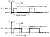
すなわち、図5(a)に示すように、感光体ドラムユニット102内のトナーが少ないとき(トナーロー)は、トナー攪拌バー303が1回転する時間(トナーセンサ周期)のうち、トナーセンサ306の発光部306aから出た光がプリズム305を通って受光部306bで透光レベルを検知する時間が長くなり、一方遮光レベルを検知する時間が短くなる。
また、図5(b)に示すように、感光体ドラムユニット102内のトナーが多いとき(トナーフル)は、トナー攪拌バー303が1回転する時間(トナーセンサ周期)のうち、トナーセンサ306の発光部306aから出た光がプリズム305を通って受光部306bで透光レベルを検知する時間が短くなり、一方遮光レベルを検知する時間が長くなる。
That is, as shown in FIG. 5A, when the toner in the
As shown in FIG. 5B, when the amount of toner in the
本実施例では、図1に示すメイン制御部201は、トナーセンサ306が検知する透光レベルの時間を監視し、所定の閾値としてのトナーロー閾値より長くなった場合、感光体ドラムユニット102内のトナーが少なくなった(トナーロー)と判定し、トナーロー閾値より短い場合、感光体ドラムユニット102内のトナーが多い(トナーフル)と判定する。
メイン制御部201は、感光体ドラムユニット102内のトナーが少なくなった(トナーロー)と判定すると、駆動部としてのトナー供給モータ301を駆動し、現像剤供給部としての搬送スパイラル302を回転制御し、トナーカートリッジ110内のトナーを感光体ドラムユニット102へ供給するトナー供給動作を行う。
In this embodiment, the
When the
トナーカートリッジ110内の搬送スパイラル302は、トナー供給モータ301の駆動により回転し、トナーカートリッジ110内のトナーをトナーダクト111に繋がる開口部へ搬送し、トナーカートリッジ110からトナーダクト111を介して感光体ドラムユニット102へトナーを供給する。
また、トナーカートリッジ110および感光体ドラムユニット102には、それぞれトナー供給シャッタ308、309が設けられており、画像形成装置101に装着したときトナー供給シャッタ308、309が開く構成になっている。
The
The
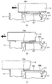
ここで、トナーカートリッジ110のトナー供給シャッタ308の構成を図4の第1の実施例におけるトナーカートリッジのシャッタの構成を示す説明図に基づいて説明する。
図4(a)はトナーカートリッジ110のトナー供給シャッタ308が閉じた状態、図4(b)はトナー供給シャッタ308が開きかけた状態、図4(c)はトナー供給シャッタ308が開いた状態を表している。
図4において、トナー供給シャッタ308は、トナーダクト111との間のトナーカートリッジ110の開口部に、開閉可能に設けられている。
Here, the configuration of the
4A shows a state where the
In FIG. 4, the
図4(a)に示すように、トナー供給シャッタ308が閉じたトナーカートリッジ110を画像形成装置101に対して図中矢印Eが示す挿入方向に挿入すると、図4(b)に示すように、挿入方向におけるトナー供給シャッタ308の下流側の端部308aが、トナーダクト111の上流側の係止部111aに当接して徐々にトナー供給シャッタ308が開く。
また、トナー供給シャッタ308の下流側の端部308aがトナーダクト111の上流側の係止部111aに当接したとき、付勢部材としてのスプリング311により付勢され、トナー供給シャッタ308に当接していた係合部310が、図中矢印Fが示すトナーカートリッジ110の方向へ突出する。
As shown in FIG. 4A, when the
Further, when the
さらに、トナーカートリッジ110を挿入し、画像形成装置101に対して完全に装着すると、図4(c)に示すように、トナー供給シャッタ308が開いた状態となる。
一方、トナーカートリッジ110を画像形成装置101から抜き取る場合、挿入方向におけるトナー供給シャッタ308の上流側の端部308bが、突出した係合部310と当接することによりトナー供給シャッタ308が閉まり、トナーカートリッジ110の開口部を閉塞する。
Further, when the
On the other hand, when the
なお、感光体ドラムユニット102のトナー供給シャッタ309も同様な構成である。また、本実施例では、トナー供給シャッタ308、309をトナーカートリッジ110および感光体ドラムユニット102に設けた構成で説明したが、トナーダクト111に設けるようにしても良く、さらにトナーカートリッジ110および感光体ドラムユニット102に設けるとともに、トナーダクト111のトナーカートリッジ110側および感光体ドラムユニット102側にも設けるようにしても良い。
The
上述した構成の作用について説明する。
まず、画像形成装置全体の動作の概略を図1および図2に基づいて説明する。
画像形成装置101は、通信回線等で接続されたコンピュータ等の上位装置から印刷指示を受けると、記憶手段に記憶した制御プログラムに基づいてメイン制御部201により各動作が制御され、印刷動作を実行する。
印刷指示を受けた画像形成装置101のメイン制御部201は、定着ユニット131の加熱加圧手段132、133をサーミスタ等の温度検出値に応じて制御することにより、所定の温度に加熱した後、ピックアップローラ122および給紙ローラ123を駆動して用紙Pを給紙トレイ121から給紙する。
The operation of the above configuration will be described.
First, the overall operation of the image forming apparatus will be described with reference to FIGS.
When the
Upon receiving the print instruction, the
メイン制御部201は、給紙した用紙Pの先端をレジストセンサ125で検出したタイミングを基準として所定のタイミングでレジストローラ126を駆動することにより、用紙Pの斜行補正を行った後、二次転写部に向けて用紙Pを搬送する。
一方、メイン制御部201は、画像処理等を行った印刷データに基づきLEDヘッド103を選択的に点灯し、電子写真プロセスにより、回転する中間転写ベルト113上にトナー像を形成し、搬送する。
The
On the other hand, the
メイン制御部201は、書き出しセンサ129で用紙Pの先端を検出したときに、用紙Pとトナー像の位置関係を抽出し、その位置関係から導き出されるタイミングで用紙Pを搬送する用紙搬送モータを一時減速および再加速することにより、二次転写ローラ130の位置で用紙Pとトナー像の先端の位置を合わせるように調整する。
メイン制御部201は、二次転写部でトナー像を用紙Pに転写した後、定着ユニット131で加熱および加圧することによりトナー像を用紙Pに定着させ、さらに用紙Pを搬送し、排出トレイ136に定着させたトナー像が下方になるようにして排出する。
When the
The
次に、画像形成装置が行うトナー供給異常検出処理を図6の第1の実施例におけるトナー供給異常検出処理の流れを示すフローチャートの図中Sで表すステップに従って図1および図3を参照しながら説明する。
まず、メイン制御部201は、トナーセンサ306が検知する透光レベルの時間を監視し、所定の閾値としてのトナーロー閾値より長くなった場合、感光体ドラムユニット102内のトナーが少なくなった(トナーロー)と判定する。
Next, the toner supply abnormality detection process performed by the image forming apparatus will be described with reference to FIGS. 1 and 3 according to the step represented by S in the flowchart showing the flow of the toner supply abnormality detection process in the first embodiment of FIG. explain.
First, the
S101:メイン制御部201は、感光体ドラムユニット102内のトナーが少なくなった(トナーロー)、すなわちトナーの供給動作が必要か否かを判定し、トナーの供給動作が必要と判定すると処理をS102へ移行し、トナーの供給動作が不要(トナーローでない)と判定するとトナーセンサ306による監視を継続する。
S102:トナーの供給動作が必要と判定したメイン制御部201は、消耗品としてのトナーカートリッジ110の交換がされることを待機し、トナーカートリッジ110の交換を検知した後、交換されたトナーカートリッジ110は最初のトナー供給であるか否かを判定し、最初のトナー供給であると判定すると処理をS103へ移行し、最初のトナー供給でないと判定すると通常のトナーロー検出動作およびトナー供給動作を行う処理へ移行する。
S101: The
S102: The
トナーカートリッジ110の交換および最初のトナー供給であるか否かの判定は、トナーカートリッジ110のメモリタグ137、138に記憶された情報に基づいて判定することができる。
例えば、トナーカートリッジ110のメモリタグ137、138に記憶されたシリアルNo209が画像形成装置101本体で記憶していたものと異なる場合、トナーカートリッジ110の交換が行われたと判定することができる。
The replacement of the
For example, if the
また、メモリタグ137、138を使用することなく、消耗品を交換するためにカバー等が開けられたことを履歴情報等で検知してトナーカートリッジ110の交換が行われたと判定するようにしても良い。なお、カバー等が開けられたことを検知してトナーカートリッジ110の交換が行われたと判定する場合、消耗品の交換だけでなく、同じ消耗品を抜き差しした場合も検知することができる。
Further, without using the memory tags 137 and 138, it may be determined that the
さらに、トナーカートリッジ110のメモリタグ137に記憶された消耗カウントが「0」である場合、最初のトナー供給であると判定することもできる。
S103:メイン制御部201は、トナー供給モータ301を駆動し、トナー供給動作を開始し、トナーカートリッジ110内の搬送スパイラル302をトナー供給モータ301の駆動により回転させ、トナーカートリッジ110からトナーダクト111を介して感光体ドラムユニット102へトナーを供給する。
Further, when the consumption count stored in the memory tag 137 of the
S103: The
S104:メイン制御部201は、トナー供給動作を開始した後のトナー供給動作で異常(トナー供給エラー)を検出したか否かを判定し、異常を検出したと判定すると処理をS105へ移行し、異常を検出していないと判定すると通常のトナーロー検出動作およびトナー供給動作を行う処理へ移行する。
トナー供給動作の異常とは、トナー供給動作中に発生する機器の異常等の要因により、トナー供給モータ301を駆動し、搬送スパイラル302を回転させてトナー供給動作を開始した後、所定の時間を経過してもドラムユニット内トナー残量検知部204がトナーロー状態の解除を検知できない異常である。
S104: The
The abnormality in the toner supply operation refers to a predetermined time after the
例えば、トナーカートリッジ110や感光体ドラムユニット102を画像形成装置101に装着するときに、トナー供給シャッタ308、309がそれぞれ開く構成になっているが、トナーカートリッジ110や感光体ドラムユニット102を画像形成装置101に対して斜めに装着した場合などはトナー供給シャッタ308、309が正常に開かず、トナー供給動作に失敗することがある。
For example, when the
S105:トナー供給動作で異常を検出したメイン制御部201は、トナー供給動作で異常(トナー供給エラー)が発生した旨を報知するトナー供給エラー画面を表示部202に表示する。
S106:メイン制御部201は、交換が行われたトナーカートリッジ110のトナー供給動作で異常を検出した回数がN回(所定の回数)未満か否かを判定し、N回未満であると判定すると処理をS108へ移行し、N回未満でない(N回以上である)と判定すると処理をS107へ移行する。
S105: The
S106: The
S107:トナー供給動作で異常を検出した回数がN回以上であると判定したメイン制御部201は、トナー供給動作で異常が検出された色のトナーカートリッジ110のメモリタグ137の消耗カウント記憶部207に記憶されている消耗カウント(トナー消費カウント)が所定値L以上であるか否かを判定し、所定値L以上であると判定すると処理をS109へ移行し、所定値L未満であると判定すると処理をS108へ移行する。
S108:消耗カウント(トナー消費カウント)が所定値L未満であると判定したメイン制御部201は、消耗品の装着状態の確認や抜き差し等、消耗品への対応を要求する画面を表示部202に表示し、本処理を終了する。
S107: The
S108: The
表示部202に表示される画面は、例えば図7に示す画面であり、図7(a)はトナーカートリッジ110の装着状態の確認を促す画面、図7(b)はドラムユニット102の装着状態の確認を促す画面、図7(c)はトナーカートリッジ110およびドラムユニット102の装着状態の確認を促す画面、図7(d)はトナーカートリッジ110の着脱を促す画面、図7(e)はドラムユニット102の着脱を促す画面、図7(f)はトナーカートリッジ110およびドラムユニット102の着脱を促す画面である。
The screen displayed on the display unit 202 is, for example, the screen shown in FIG. 7, FIG. 7A is a screen for prompting confirmation of the mounting state of the
このように、メイン制御部201は、ドラムユニット内トナー残量検知部204がトナーロー状態の解除を検知できない異常を検出した結果と、トナーカートリッジ110のメモリタグ137の消耗カウント記憶部207に記憶されている消耗カウントとに基づいてユーザによるトナーカートリッジ110やドラムユニット102への対応を促す画面を表示部202に表示する。
As described above, the
S109:メイン制御部201は、トナー供給動作で異常が検出された色のトナーカートリッジ110のメモリタグ137の消耗カウント記憶部207に記憶されている消耗カウント(トナー消費カウント)が所定値L以上であると判定すると、トナー供給動作で異常が検出された色のトナーカートリッジ110のメモリタグ137の寿命フラグ208に当該トナーカートリッジ110が寿命に達した旨の情報(トナーカートリッジ110内のトナーが所定量以下であることを表すトナー量情報)を書き込み、以降のトナー供給動作や使用を不可能にし、本処理を終了する。
S109: The
このように、本実施例では、メイン制御部201は、消耗品が交換されたことを検知した後、最初のトナー供給動作で連続して機器の異常を検知した場合であっても、トナーカートリッジ110のメモリタグ137に記憶されている消耗カウント(トナー消費カウント)が所定値L未満であるとき、トナー供給動作で異常が検出された色のトナーカートリッジ110のメモリタグ137の寿命フラグ208に当該トナーカートリッジ110が寿命に達した旨の情報の書き込みを中止するとともに、消耗品の装着状態の確認や抜き差しを要求する画面を表示部202に表示する。このように、消耗品の装着状態の確認や抜き差しを要求する画面を表示部202に表示することにより、ユーザにトナー供給シャッタ307、308等の機器の状態確認を促す。
As described above, in this embodiment, the
また、トナーカートリッジ110のメモリタグ137に記憶されている消耗カウント(トナー消費カウント)が所定値L以上であるとき、すなわち既にトナー供給動作が成功した実績のある消耗品に関しては、「実際にトナーの残量が空に近くなっている」、「トナー供給シャッタ以外のトナー供給スパイラル、トナー攪拌バー等の不具合」等の可能性を考慮し、トナー供給動作で異常が検出された色のトナーカートリッジ110のメモリタグ137の寿命フラグ208に当該トナーカートリッジ110が寿命に達した旨の情報を書き込み、以降のトナー供給動作を禁止する。
In addition, when the consumption count (toner consumption count) stored in the memory tag 137 of the
ここで、トナー供給モータ301の不具合、すなわち何らかの原因によりトナー供給モータ301が回転しないことでもトナー供給動作の異常は起こり得るが、これに関しては別途過電流検知等の安全対策や異常検知を行うものとする。
なお、本実施例では、S107において、トナー供給動作で異常が検出された色のトナーカートリッジ110のメモリタグ137の消耗カウント記憶部207に記憶されている消耗カウント(トナー消費カウント)が所定値L以上であるか否かを判定するようにしたが、トナーカートリッジ110のメモリタグ137の寿命フラグ208の有無を判定するようにしても良い。また、それ以外の判定基準となりえる要素をメモリタグ137内に設けるようにしても良い。
Here, a malfunction of the
In this embodiment, the consumption count (toner consumption count) stored in the consumption
次に、比較例の画像形成装置が行うトナー供給異常検出処理を図11の比較例におけるトナー供給異常検出処理の流れを示すフローチャートの図中Sで表すステップに従って図1および図3を参照しながら説明する。
まず、メイン制御部201は、トナーセンサ306が検知する透光レベルの時間を監視し、所定の閾値としてのトナーロー閾値より長くなった場合、感光体ドラムユニット102内のトナーが少なくなった(トナーロー)と判定する。
Next, the toner supply abnormality detection process performed by the image forming apparatus of the comparative example will be described with reference to FIGS. 1 and 3 according to the step indicated by S in the flowchart showing the flow of the toner supply abnormality detection process of the comparative example of FIG. explain.
First, the
S301〜305:図6に示すS101〜S105と同様の処理なのでその説明を省略する。
S306:メイン制御部201は、トナー供給動作で異常を検出した回数がN回未満か否かを判定し、N回未満であると判定すると本処理を終了し、N回未満でない(N回以上である)と判定すると処理をS307へ移行する。
S301 to S305: The processing is the same as S101 to S105 shown in FIG.
S306: The
S307:メイン制御部201は、トナー供給動作で異常が検出された色のトナーカートリッジ110のメモリタグ137の寿命フラグ208に当該トナーカートリッジ110が寿命に達した旨の情報を書き込み、以降のトナー供給動作や使用を不可能にし、本処理を終了する。
比較例では、トナー供給動作で異常を検出した回数がN回未満でない(N回以上である)と判定すると、トナー供給動作で異常が検出された色のトナーカートリッジ110のメモリタグ137の寿命フラグ208に当該トナーカートリッジ110が寿命に達した旨の情報を書き込み、以降のトナー供給動作や使用を不可能にしている。
S307: The
In the comparative example, if it is determined that the number of times the abnormality is detected in the toner supply operation is not less than N (N or more), the life flag of the memory tag 137 of the
これは、トナー供給シャッタ308、309等が開いていない状態でトナー供給動作を行うことにより機構的な破損等が発生しないようにするためであるが、トナーカートリッジ110内に大量のトナーが存在するにもかかわらず、トナー供給動作の異常が発生したことにより、メモリタグ137の寿命フラグ208に当該トナーカートリッジ110が寿命に達した旨の情報を書き込み、以降のトナー供給動作や使用が不可能になってしまい、ユーザが多大な不利益を被ってしまうという問題があった。
This is to prevent mechanical damage or the like by performing the toner supply operation in a state where the
このような問題に鑑み、本実施例では、トナー供給動作で異常が検出された色のトナーカートリッジ110に所定量以上のトナーが残っていると判定した場合、トナー供給動作で異常が検出されたとしても、メモリタグ137の寿命フラグ208に当該トナーカートリッジ110が寿命に達した旨の情報を書き込むことなく、機構的な破損等が発生しないように、消耗品の装着状態の確認や抜き差しをユーザに要求する画面を表示部202に表示するようにしている。
このように本実施例では、トナー供給動作で異常が検出された場合、消耗品としてのトナーカートリッジへの対応をユーザに促すようにしたことにより、トナーが正常に供給されないことを抑制することができる。
In view of such a problem, in this embodiment, when it is determined that a predetermined amount or more of toner remains in the
As described above, according to the present exemplary embodiment, when an abnormality is detected in the toner supply operation, the user is encouraged to deal with the toner cartridge as a consumable, thereby preventing the toner from being normally supplied. it can.
また、消耗品の交換または抜き差しを検出した後、最初のトナー供給動作で連続して異常が発生した場合であっても、画像形成装置101がトナーカートリッジ110のメモリタグ137に記憶されている消耗カウントを参照し、該消耗カウントが所定の閾値未満であるとき当該メモリタグ137への寿命フラグの書込みを行わないようにしたことにより当該トナーカートリッジ110に大量のトナーが残っているのにも関わらず当該トナーカートリッジを使用不能にしてしまうことを回避することができるとともに、消耗品の装着状態の確認や抜き差しをユーザに要求するようにしたことにより画像形成装置101の機構的な破損を避けることができる。
In addition, even if an abnormality occurs continuously in the first toner supply operation after detecting the replacement or removal of the consumables, the
以上説明したように、第1の実施例では、トナーが正常に供給されないことを抑制することができるという効果が得られる。
また、トナーカートリッジに大量のトナーが残っているのにも関わらず当該トナーカートリッジを使用不能にしてしまうことを回避することができるとともに、画像形成装置の機構的な破損を避けることができるという効果が得られる。
As described above, in the first embodiment, the effect that the toner is not normally supplied can be obtained.
Further, it is possible to avoid making the toner cartridge unusable even though a large amount of toner remains in the toner cartridge, and to avoid mechanical damage of the image forming apparatus. Is obtained.
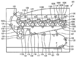
第2の実施例の構成は、第1の実施例の画像形成装置に特色の画像形成部を設けたものとなっている。その第2の実施例の構成を図8の第2の実施例における画像形成装置の構成を示す概略側断面図に基づいて説明する。なお、上述した第1の実施例と同様の部分は、同一の符号を付してその説明を省略する。 The configuration of the second embodiment is such that a special color image forming section is provided in the image forming apparatus of the first embodiment. The configuration of the second embodiment will be described based on a schematic side sectional view showing the configuration of the image forming apparatus in the second embodiment of FIG. Note that parts similar to those of the first embodiment described above are denoted by the same reference numerals and description thereof is omitted.
図8において、画像形成装置101は、使用するトナーの色毎に複数配置された感光体ドラムユニット102(K、C、M、Y、G)、トナーカートリッジ110(K、C、M、Y、G)、およびトナーダクト111(K、C、M、Y、G)を有し、特定色のトナー(以下、「特色トナー」という。)を扱う感光体ドラムユニット102Gと、トナーカートリッジ110Gと、一次転写ローラ112Gとを有している。
特色トナーを扱う感光体ドラムユニット102Gとトナーカートリッジ110Gとは、トナーダクト111Gを介して接続されている。ここで、特色トナーとは、例えばグロス(クリア:透明)トナー、ホワイト色トナー、金色トナー、銀色トナー、マイカトナーなどであり、通常のYMCKのトナーとは異なる特殊なトナーである。
In FIG. 8, the
The
感光体ドラムユニット102G、トナーカートリッジ110G、およびトナーダクト111Gは、印刷の用途によって付け替え可能とするため、それぞれ画像形成装置101に対して着脱可能に構成されている。なお、トナーダクト111K(C、M、Y)は画像形成装置101に取り付けられているが、トナーダクト111Gは画像形成装置101に対して着脱可能に構成されている。これは、感光体ドラムユニット102Gおよびトナーカートリッジ110Gの交換時に、トナーダクト111Gに付着したトナーが交換した感光体ドラムユニット102Gのトナーと混色しないようにするためである。
このように構成された画像形成装置101は、図中矢印Bが示す中間転写ベルト113の回転方向における上流側から感光体ドラムユニット102G、102Y、102M、102C、102Kが順に配置され、それぞれの感光体ドラム108に形成されたトナー像が一次転写ローラ112により中間転写ベルト113上に一次転写される。
The
In the
なお、画像形成装置101は、中間転写ベルト113を張架するための逆屈折ローラ151を備えている。この逆屈折ローラ151は、中間転写ベルト113を屈折させるものであり、中間転写ベルト113の回転方向における中間転写ベルトクリーニングブレード119より上流側に配置されているため、バイアス電圧を印加してクリーニングするようにしても良い。
また、第2の実施例におけるトナー供給機構およびトナー残量検知部の構成は、感光体ドラムユニット102Gおよびトナーカートリッジ110Gを含め、図3に示す第1の実施例におけるトナー供給機構およびトナー残量検知部の構成と同様なのでその説明を省略する。
The
Further, the configuration of the toner supply mechanism and the toner remaining amount detection unit in the second embodiment includes the
上述した構成の作用について説明する。なお、画像形成装置全体の動作は、第1の実施例と同様なのでその説明を省略する。
画像形成装置が行うトナー供給異常検出処理を図9の第2の実施例におけるトナー供給異常検出処理の流れを示すフローチャートの図中Sで表すステップに従って図1および図3を参照しながら説明する。
The operation of the above configuration will be described. Since the operation of the entire image forming apparatus is the same as that of the first embodiment, the description thereof is omitted.
The toner supply abnormality detection process performed by the image forming apparatus will be described with reference to FIGS. 1 and 3 according to the step indicated by S in the flowchart showing the flow of the toner supply abnormality detection process in the second embodiment of FIG.
まず、メイン制御部201は、トナーセンサ306が検知する透光レベルの時間を監視し、所定の閾値としてのトナーロー閾値より長くなった場合、感光体ドラムユニット102内のトナーが少なくなった(トナーロー)と判定する。
S201〜S205:図6に示すS101〜S105と同様の処理なのでその説明を省略する。
S206:メイン制御部201は、トナー供給動作で異常を検出した回数がN回未満か否かを判定し、N回未満であると判定すると処理をS209へ移行し、N回未満でない(N回以上である)と判定すると処理をS207へ移行する。
First, the
S201 to S205: Since they are the same as S101 to S105 shown in FIG.
S206: The
S207:トナー供給動作で異常を検出した回数がN回以上であると判定したメイン制御部201は、トナー供給動作で異常が検出された色のトナーカートリッジ110のメモリタグ137の消耗カウント記憶部207に記憶されている消耗カウント(トナー消費カウント)が所定値L以上であるか否かを判定し、所定値L以上であると判定すると処理をS208へ移行し、所定値L未満であると判定すると処理をS209へ移行する。
S208:消耗カウント(トナー消費カウント)が所定値L以上であると判定したメイン制御部201は、トナー供給動作で異常が検出された色のトナーカートリッジ110のメモリタグ137の寿命フラグ208に当該トナーカートリッジ110が寿命に達した旨の情報を書き込み、以降のトナー供給動作や使用を不可能にし、本処理を終了する。
S207: The
S208: The
S209:消耗カウント(トナー消費カウント)が所定値L未満であると判定したメイン制御部201は、トナー供給動作で異常が検出された色のトナーカートリッジ110は特色(トナーカートリッジ110G)であるか否かを判定し、特色(トナーカートリッジ110G)であると判定すると処理をS210へ移行し、特色(トナーカートリッジ110G)でない、すなわちトナーカートリッジ110(K、C、M、Y)のいずれかであると判定すると処理をS211へ移行する。
S209: When determining that the consumption count (toner consumption count) is less than the predetermined value L, the
S210:トナー供給動作で異常が検出された色のトナーカートリッジが特色のトナーカートリッジ110Gであると判定したメイン制御部201は、特色のダクトユニットとしての特色のトナーダクト111Gを含む特色のトナーカートリッジ110G、特色のドラムユニット102Gの状態の確認を要求する画面を表示部202に表示し、本処理を終了する。
S210: The
表示部202に表示される画面は、例えば図10に示す画面であり、図10(a)は特色のトナーカートリッジ110Gの装着状態の確認を促す画面、図10(b)は特色のドラムユニット102Gの装着状態の確認を促す画面、図10(c)は特色のトナーダクト111Gの装着状態の確認を促す画面、図10(d)は特色のトナーカートリッジ110G、特色のドラムユニット102Gおよび特色のトナーダクト111Gの装着状態の確認を促す画面、図10(e)は特色のトナーカートリッジ110Gの着脱を促す画面、図10(f)は特色のドラムユニット102Gの着脱を促す画面、図10(g)は特色のトナーダクト111Gの着脱を促す画面、図10(h)は特色のトナーカートリッジ110G、特色のドラムユニット102Gおよび特色のトナーダクト111Gの着脱を促す画面である。
The screen displayed on the display unit 202 is, for example, the screen shown in FIG. 10, FIG. 10A is a screen for prompting confirmation of the mounting state of the special
このように、本実施例では、メイン制御部201は、画像形成装置101に対して着脱可能な特色のトナーダクト111Gに接続される特色のトナーカートリッジ110Gおよび感光体ドラムユニット102Gにおいてトナー供給動作で異常が検出された場合、表示部202にトナーダクト111Gの状態の確認を促す表示を行う。
As described above, in this embodiment, the
S211:トナー供給動作で異常が検出された色のトナーカートリッジがトナーカートリッジ110(K、C、M、Y)のいずれかであると判定したメイン制御部201は、第1の実施例における図6のS108と同様に、トナーダクト111Gを含め消耗品の装着状態の確認や抜き差し等、消耗品への対応を要求する画面を表示部202に表示し、本処理を終了する。
S211: The
このように、画像形成装置101に対して着脱可能な特色の感光体ドラムユニット102Gにおけるトナー供給動作で異常が検出された場合、トナーカートリッジ110G、感光体ドラムユニット102G、またはトナーダクト111Gの消耗品の装着状態の確認や抜き差しを要求する画面を表示部202に表示するようにしたことにより、ユーザに対してより適切な誘導を行うことができ、画像形成装置の機構的な破損を避けることができる。
As described above, when an abnormality is detected in the toner supply operation of the special-color
以上説明したように、第2の実施例では、第1の実施例の効果に加え、画像形成装置に対して着脱可能な特色の感光体ドラムユニットにおけるトナー供給動作で異常が検出された場合、ユーザに対してより適切な誘導を行うことができ、画像形成装置の機構的な破損を避けることができるという効果が得られる。
なお、第1の実施例および第2の実施例では、画像形成装置を電子写真方式のプリンタとして説明したが、それに限られることなく、複写機、ファクシミリ装置、またはこれらの機能を兼ね備えた複合機(MFP)等としても良い。
As described above, in the second embodiment, in addition to the effects of the first embodiment, when an abnormality is detected in the toner supply operation in the photosensitive drum unit of the special color that is detachable from the image forming apparatus, the user Therefore, it is possible to perform more appropriate guidance and to avoid the mechanical damage of the image forming apparatus.
In the first and second embodiments, the image forming apparatus has been described as an electrophotographic printer. However, the image forming apparatus is not limited thereto, and is not limited thereto. A copier, a facsimile machine, or a multifunction machine having these functions. (MFP) or the like may be used.
101 画像形成装置
102 感光体ドラムユニット
103 LEDヘッド
104 帯電ローラ
105 供給ローラ
106 現像ローラ
107 現像ブレード
108 感光体ドラム
109 感光体ドラムクリーニングブレード
110 トナーカートリッジ
137、138 メモリタグ
201 メイン制御部
202 表示部
203 メモリタグ読み書き制御部
204 ドラムユニット内トナー残量検知部
205 消耗品寿命検知部
207 消耗カウント記憶部
208 寿命フラグ
209 シリアルNo
DESCRIPTION OF
Claims (11)
画像形成部と、
前記画像形成部内の所定位置で現像剤を検出する検出部と、
前記画像形成部に対して着脱可能に設けられた現像剤収容部と、
前記現像剤収容部の使用状態を表す値を記憶する記憶部と、
前記現像剤収容部から前記画像形成部に現像剤を供給する現像剤供給部と、
前記現像剤供給部を制御する制御部と、
を有し、
前記制御部は、
前記検出部の検出結果と前記使用状態を表す値とに基づいて、前記表示部に、着脱可能な前記現像剤収容部への対応を促す表示を行うことを特徴とする画像形成装置。 A display for displaying information;
An image forming unit;
A detection unit for detecting a developer at a predetermined position in the image forming unit;
A developer accommodating portion detachably provided to the image forming portion;
A storage unit for storing a value representing a use state of the developer storage unit;
A developer supply unit for supplying a developer from the developer containing unit to the image forming unit;
A control unit for controlling the developer supply unit;
Have
The controller is
An image forming apparatus characterized in that, based on a detection result of the detection unit and a value indicating the use state, a display for prompting the display unit to respond to the removable developer storage unit is performed.
前記制御部は、
前記現像剤供給部による供給動作を開始した後、前記検出部で現像剤が検出されなかったときに、前記使用状態を表す値が所定値以下であった場合、前記表示部に、着脱可能な前記現像剤収容部への対応を促す表示を行うことを特徴とする画像形成装置。 The image forming apparatus according to claim 1.
The controller is
After the supply operation by the developer supply unit is started, when the developer is not detected by the detection unit, if the value indicating the use state is equal to or less than a predetermined value, the display unit can be attached and detached. An image forming apparatus, characterized in that a display for prompting correspondence to the developer containing portion is performed.
前記現像剤供給部を駆動する駆動部を有し、
前記制御部は、
前記現像剤供給部を所定時間駆動した後、前記検出部で現像剤が検出されなかったときに、前記使用状態を表す値が所定値以下であった場合、前記表示部に、着脱可能な前記現像剤収容部への対応を促す表示を行うことを特徴とする画像形成装置。 The image forming apparatus according to claim 1.
A drive unit for driving the developer supply unit;
The controller is
After the developer supply unit is driven for a predetermined time, when the developer is not detected by the detection unit, if the value indicating the use state is equal to or less than a predetermined value, the display unit can be attached to and detached from the display unit. An image forming apparatus, characterized in that a display for prompting correspondence to a developer container is performed.
前記対応を促す表示は、前記現像剤収容部の装着状態の確認を促す表示であることを特徴とする画像形成装置。 The image forming apparatus according to any one of claims 1 to 3,
The image forming apparatus according to claim 1, wherein the display for prompting the correspondence is a display for prompting confirmation of a mounting state of the developer accommodating portion.
前記対応を促す表示は、前記現像剤収容部の着脱を促す表示であることを特徴とする画像形成装置。 The image forming apparatus according to any one of claims 1 to 3,
2. The image forming apparatus according to claim 1, wherein the display for prompting the correspondence is a display for prompting attachment / detachment of the developer accommodating portion.
前記記憶部は、前記現像剤収容部に配置され、
前記制御部は、
前記使用状態を表す値が所定値以上であった場合、前記画像形成部内の現像剤量が所定量以下であることを表す現像剤量情報を前記記憶部に書き込むことを特徴とする画像形成装置。 The image forming apparatus according to claim 1, wherein:
The storage unit is disposed in the developer container.
The controller is
When the value indicating the use state is equal to or greater than a predetermined value, developer amount information indicating that the amount of developer in the image forming unit is equal to or less than a predetermined amount is written in the storage unit. .
前記画像形成部と前記現像剤収容部とを繋ぐ現像剤供給路を有することを特徴とする画像形成装置。 The image forming apparatus according to any one of claims 1 to 6,
An image forming apparatus having a developer supply path that connects the image forming unit and the developer containing unit.
前記現像剤供給路との間の前記現像剤収容部の開口部にシャッタを有することを特徴とする画像形成装置。 The image forming apparatus according to claim 7.
An image forming apparatus comprising a shutter at an opening of the developer accommodating portion between the developer supply path and the developer supply path.
前記制御部は、
前記現像剤供給路が装置本体に対して着脱可能である場合に、前記表示部に、前記現像剤供給路の確認を促す表示を行うことを特徴とする画像形成装置。 The image forming apparatus according to claim 7 or 8,
The controller is
An image forming apparatus, wherein when the developer supply path is detachable from the apparatus main body, a display for prompting confirmation of the developer supply path is displayed on the display unit.
前記制御部は、
前記現像剤供給路が装置本体に対して着脱可能である場合に、前記表示部に、前記現像剤供給路の着脱を促す表示を行うことを特徴とする画像形成装置。 The image forming apparatus according to claim 7 or 8,
The controller is
An image forming apparatus, wherein when the developer supply path is detachable from the apparatus main body, a display that prompts the display section to attach / detach the developer supply path is performed.
前記画像形成部および前記現像剤供給路は、使用する現像剤の色毎に複数配置され、
前記制御部は、
特定色の現像剤収容部から特定色の画像形成部への現像剤の供給が正常に行われなかったとき、前記表示部に、前記特定色の現像剤供給路の確認を促す表示を行うことを特徴とする画像形成装置。 The image forming apparatus according to claim 7.
A plurality of the image forming unit and the developer supply path are arranged for each color of the developer to be used,
The controller is
When the developer is not normally supplied from the developer container of the specific color to the image forming unit of the specific color, a display prompting confirmation of the developer supply path of the specific color is displayed on the display unit An image forming apparatus.
Priority Applications (1)
| Application Number | Priority Date | Filing Date | Title |
|---|---|---|---|
| JP2014127426A JP6257041B2 (en) | 2014-06-20 | 2014-06-20 | Image forming apparatus |
Applications Claiming Priority (1)
| Application Number | Priority Date | Filing Date | Title |
|---|---|---|---|
| JP2014127426A JP6257041B2 (en) | 2014-06-20 | 2014-06-20 | Image forming apparatus |
Publications (2)
| Publication Number | Publication Date |
|---|---|
| JP2016006468A true JP2016006468A (en) | 2016-01-14 |
| JP6257041B2 JP6257041B2 (en) | 2018-01-10 |
Family
ID=55224947
Family Applications (1)
| Application Number | Title | Priority Date | Filing Date |
|---|---|---|---|
| JP2014127426A Expired - Fee Related JP6257041B2 (en) | 2014-06-20 | 2014-06-20 | Image forming apparatus |
Country Status (1)
| Country | Link |
|---|---|
| JP (1) | JP6257041B2 (en) |
Cited By (2)
| Publication number | Priority date | Publication date | Assignee | Title |
|---|---|---|---|---|
| JP2019164336A (en) * | 2018-03-14 | 2019-09-26 | キヤノン株式会社 | Image forming device, information processing method, and program |
| WO2021039810A1 (en) * | 2019-08-30 | 2021-03-04 | Brother Kogyo Kabushiki Kaisha | Toner cartridge |
Citations (6)
| Publication number | Priority date | Publication date | Assignee | Title |
|---|---|---|---|---|
| JP2005062848A (en) * | 2003-07-29 | 2005-03-10 | Canon Inc | Image forming apparatus and its control method |
| JP2005309322A (en) * | 2004-04-26 | 2005-11-04 | Sharp Corp | Toner residual quantity detection method and image forming apparatus detecting toner residual quantity by that method |
| JP2006251067A (en) * | 2005-03-08 | 2006-09-21 | Konica Minolta Business Technologies Inc | Image forming apparatus and processing program for detecting toner running-out |
| JP2006301349A (en) * | 2005-04-21 | 2006-11-02 | Sharp Corp | Developing device |
| JP2012032736A (en) * | 2010-08-03 | 2012-02-16 | Konica Minolta Business Technologies Inc | Image forming apparatus |
| JP2013097005A (en) * | 2011-10-27 | 2013-05-20 | Canon Inc | Image forming apparatus |
-
2014
- 2014-06-20 JP JP2014127426A patent/JP6257041B2/en not_active Expired - Fee Related
Patent Citations (6)
| Publication number | Priority date | Publication date | Assignee | Title |
|---|---|---|---|---|
| JP2005062848A (en) * | 2003-07-29 | 2005-03-10 | Canon Inc | Image forming apparatus and its control method |
| JP2005309322A (en) * | 2004-04-26 | 2005-11-04 | Sharp Corp | Toner residual quantity detection method and image forming apparatus detecting toner residual quantity by that method |
| JP2006251067A (en) * | 2005-03-08 | 2006-09-21 | Konica Minolta Business Technologies Inc | Image forming apparatus and processing program for detecting toner running-out |
| JP2006301349A (en) * | 2005-04-21 | 2006-11-02 | Sharp Corp | Developing device |
| JP2012032736A (en) * | 2010-08-03 | 2012-02-16 | Konica Minolta Business Technologies Inc | Image forming apparatus |
| JP2013097005A (en) * | 2011-10-27 | 2013-05-20 | Canon Inc | Image forming apparatus |
Cited By (7)
| Publication number | Priority date | Publication date | Assignee | Title |
|---|---|---|---|---|
| JP2019164336A (en) * | 2018-03-14 | 2019-09-26 | キヤノン株式会社 | Image forming device, information processing method, and program |
| JP7353767B2 (en) | 2018-03-14 | 2023-10-02 | キヤノン株式会社 | Image forming device, information processing method and program |
| WO2021039810A1 (en) * | 2019-08-30 | 2021-03-04 | Brother Kogyo Kabushiki Kaisha | Toner cartridge |
| JP2021039176A (en) * | 2019-08-30 | 2021-03-11 | ブラザー工業株式会社 | Toner cartridge |
| US11099501B2 (en) | 2019-08-30 | 2021-08-24 | Brother Kogyo Kabushiki Kaisha | Toner cartridge having toner memory and attachable to drum cartridge having drum memory |
| US11454899B2 (en) | 2019-08-30 | 2022-09-27 | Brother Kogyo Kabushiki Kaisha | Toner cartridge having toner memory and attachable to drum cartridge having drum memory |
| JP7358849B2 (en) | 2019-08-30 | 2023-10-11 | ブラザー工業株式会社 | toner cartridge |
Also Published As
| Publication number | Publication date |
|---|---|
| JP6257041B2 (en) | 2018-01-10 |
Similar Documents
| Publication | Publication Date | Title |
|---|---|---|
| JP4577401B2 (en) | Image forming apparatus and process cartridge | |
| JP2011242518A (en) | Image forming apparatus | |
| US8131162B2 (en) | Image forming apparatus for detecting a non-qualified developer cartridge | |
| JP5426624B2 (en) | Image forming apparatus | |
| JP5241448B2 (en) | Process cartridge and image forming apparatus | |
| JP5409751B2 (en) | Replacement member management method, electronic device replacement member management method, electronic device, image forming apparatus, and replacement member management system | |
| JP2012053361A (en) | Image forming device and image forming method | |
| JP6257041B2 (en) | Image forming apparatus | |
| JP2008185971A (en) | Image forming apparatus | |
| JP6445361B2 (en) | Image forming apparatus | |
| JP2012133203A (en) | Electronic device and image forming apparatus | |
| JP2013057841A (en) | Image formation apparatus, control method for image formation apparatus, and control program for image formation apparatus | |
| JP2015143760A (en) | image forming apparatus | |
| JP2009265331A (en) | Fixing device and image forming apparatus including the same | |
| JP6557770B2 (en) | Image forming apparatus | |
| JP6031816B2 (en) | Printing device | |
| JP2013076813A (en) | Image forming device and image forming method | |
| JP4722170B2 (en) | Process unit and image forming apparatus | |
| JP2009139451A (en) | Printer | |
| JP5097605B2 (en) | Image forming apparatus and waste developer collecting apparatus | |
| US8965247B2 (en) | Image formation apparatus and fixation device | |
| JP4731588B2 (en) | Image forming apparatus | |
| US10852692B1 (en) | Image forming apparatus and image forming method | |
| JP2012137520A (en) | Image forming apparatus | |
| JP2012247699A (en) | Image forming apparatus |
Legal Events
| Date | Code | Title | Description |
|---|---|---|---|
| A621 | Written request for application examination |
Free format text: JAPANESE INTERMEDIATE CODE: A621 Effective date: 20160914 |
|
| A977 | Report on retrieval |
Free format text: JAPANESE INTERMEDIATE CODE: A971007 Effective date: 20170607 |
|
| A131 | Notification of reasons for refusal |
Free format text: JAPANESE INTERMEDIATE CODE: A131 Effective date: 20170620 |
|
| A521 | Request for written amendment filed |
Free format text: JAPANESE INTERMEDIATE CODE: A523 Effective date: 20170818 |
|
| TRDD | Decision of grant or rejection written | ||
| A01 | Written decision to grant a patent or to grant a registration (utility model) |
Free format text: JAPANESE INTERMEDIATE CODE: A01 Effective date: 20171107 |
|
| A61 | First payment of annual fees (during grant procedure) |
Free format text: JAPANESE INTERMEDIATE CODE: A61 Effective date: 20171201 |
|
| R150 | Certificate of patent or registration of utility model |
Ref document number: 6257041 Country of ref document: JP Free format text: JAPANESE INTERMEDIATE CODE: R150 |
|
| LAPS | Cancellation because of no payment of annual fees |