JP2016000187A - Stimulator - Google Patents

Stimulator Download PDF

Info

Publication number
JP2016000187A
JP2016000187A JP2014231993A JP2014231993A JP2016000187A JP 2016000187 A JP2016000187 A JP 2016000187A JP 2014231993 A JP2014231993 A JP 2014231993A JP 2014231993 A JP2014231993 A JP 2014231993A JP 2016000187 A JP2016000187 A JP 2016000187A
Authority
JP
Japan
Prior art keywords
displacement
core
head
stimulator
user
Prior art date
Legal status (The legal status is an assumption and is not a legal conclusion. Google has not performed a legal analysis and makes no representation as to the accuracy of the status listed.)
Pending
Application number
JP2014231993A
Other languages
Japanese (ja)
Inventor
松下 剛
Takeshi Matsushita
剛 松下
Current Assignee (The listed assignees may be inaccurate. Google has not performed a legal analysis and makes no representation or warranty as to the accuracy of the list.)
MTG Co Ltd
Original Assignee
MTG Co Ltd
Priority date (The priority date is an assumption and is not a legal conclusion. Google has not performed a legal analysis and makes no representation as to the accuracy of the date listed.)
Filing date
Publication date
Application filed by MTG Co Ltd filed Critical MTG Co Ltd
Priority to JP2014231993A priority Critical patent/JP2016000187A/en
Priority to PCT/JP2015/063642 priority patent/WO2015178253A1/en
Priority to TW104115774A priority patent/TWI632938B/en
Priority to CN201520324135.3U priority patent/CN205019371U/en
Priority to CN201510256165.XA priority patent/CN105078724A/en
Publication of JP2016000187A publication Critical patent/JP2016000187A/en
Pending legal-status Critical Current

Links

Images

Abstract

PROBLEM TO BE SOLVED: To provide a stimulator capable of urging repeated use to a user by bringing pleasure and comfortableness feeling to the user.SOLUTION: A stimulator 1 includes a core 10, and a plurality of displacement parts 20 disposed displaceably on the outer surface 14 of the core 10, and each displacement part 20 is constituted so as to generate click feeling following displacement. Preferably, each displacement part 20 is energized to a direction in which an initial attitude is maintained, and constituted displaceably against an energization force.

Description

本発明は、刺激具に関する。   The present invention relates to a stimulator.

従来、掌握することにより、掌や指に刺激を与えるように構成された刺激具がある。例えば、特許文献1には、コアとその外表に外方に向けて付勢された複数の突起部とを備え、コアを掌握することにより各突起部が掌や指により付勢力に抗してコアの内方に変位するとともに、掌や指がその付勢力により押圧刺激を受けるように構成されたものが開示されている。   2. Description of the Related Art Conventionally, there is a stimulator configured to stimulate a palm or a finger by grasping it. For example, Patent Document 1 includes a core and a plurality of protrusions urged outward on the outer surface thereof, and each protrusion is resisted against an urging force by a palm or a finger by grasping the core. A structure is disclosed in which the palm and fingers are displaced by the urging force while being displaced inward of the core.

実開昭58−168361号公報Japanese Utility Model Publication No. 58-168361

しかしながら、特許文献1に開示の構成では、突起部は掌や指によって押圧されることにより、その押圧力の大きさに応じてコアの内方に所定量移動(変位)するだけであって、使用者は突起部を確実に所定量変位させたことを認識し難い場合がある。そのため、突起部を繰り返し押圧したり、複数の突起部を一斉に押圧したりしたときの体感が低く、使用者に突起部を押圧することによって楽しさや心地よい体感を与えることは困難である。そのため、使用者に当該刺激具を繰り返し使用することを促すには改善の余地がある。   However, in the configuration disclosed in Patent Document 1, the protrusion is only moved (displaced) by a predetermined amount inward of the core according to the magnitude of the pressing force when pressed by a palm or a finger. In some cases, it is difficult for the user to recognize that the protrusion has been displaced by a predetermined amount. Therefore, when the protrusion is repeatedly pressed or when a plurality of protrusions are pressed all at once, it is difficult to give the user a pleasant and pleasant experience by pressing the protrusion. Therefore, there is room for improvement in prompting the user to repeatedly use the stimulator.

本発明は、かかる背景に鑑みてなされたもので、使用者に楽しさと心地よい体感をもたらして、繰り返し使用することを促すことができる刺激具を提供しようとするものである。   The present invention has been made in view of such a background, and an object of the present invention is to provide a stimulating device that can provide a user with a pleasant and pleasant experience and can encourage repeated use.

本発明の一態様は、コアと、該コアの外表に変位可能に配設された複数の変位部と、を備え、
上記各変位部は、変位に伴ってクリック感を発生させるように構成されていることを特徴とする刺激具にある。
One aspect of the present invention includes a core, and a plurality of displacement portions disposed on the outer surface of the core so as to be displaceable.
Each said displacement part exists in the stimulator characterized by generating so that a click feeling may be generated with a displacement.

上記刺激具においては、コアの外表に配設された複数の変位部が変位することに伴ってクリック感が発生される。使用者は当該クリック感を得ることにより、変位部を確実に変位させたことを認識することができる。そして、変位部を繰り返し変位させたり、複数の変位部を一斉に変位させたりすることによって多数のクリック感が得られるとともに、当該多数のクリック感が相俟って楽しさと心地よい体感が使用者にもたらされることとなる。これにより、使用者に当該刺激具を繰り返し使用することを促すことができる。そして、使用者は当該刺激具を繰り返し掌握して指や掌によって変位部を繰り返し変位させたり、当該刺激具を首筋、肩、背中、四肢などの様々な部分に繰り返し押し当てて体の様々な部分によって変位部を繰り返し変位させたりすることで、指、掌、首筋、肩、背中、四肢などの体の様々な部分が効果的にマッサージされることとなる。   In the stimulator, a click feeling is generated as the plurality of displacement portions arranged on the outer surface of the core are displaced. The user can recognize that the displacement portion has been reliably displaced by obtaining the click feeling. A number of click feelings can be obtained by repeatedly displacing the displacement part or by displacing a plurality of displacement parts at the same time, and the user can have a pleasant and comfortable experience with the many click feelings. Will be brought. This can prompt the user to use the stimulator repeatedly. The user repeatedly grasps the stimulator and repeatedly displaces the displacement part with a finger or palm, or repeatedly presses the stimulator against various parts such as the neck, shoulders, back, and extremities. By repeatedly displacing the displacement part by the part, various parts of the body such as fingers, palms, neck, shoulders, back, and limbs are effectively massaged.

さらに、使用者は掌や指により変位部を繰り返し変位させる場合には、掌や指を介してクリック感や押圧感を繰り返し知覚することとなる。これにより、掌や指を介して使用者の脳に繰り返し刺激を与えることができる。その結果、使用者の脳の活性化を促す効果が奏される。   Further, when the user repeatedly displaces the displacement portion with the palm or finger, the user repeatedly perceives a click feeling or a pressing feeling through the palm or finger. Thereby, a stimulus can be repeatedly given to a user's brain via a palm or a finger. As a result, there is an effect of promoting the activation of the user's brain.

以上のごとく、本発明によれば、使用者に楽しさと心地よい体感をもたらして、繰り返し使用することを促すことができる刺激具を提供することができる。   As described above, according to the present invention, it is possible to provide a stimulator that can provide a user with a pleasant and pleasant experience and can prompt the user to use it repeatedly.

実施例1における、刺激具の正面図。The front view of the stimulator in Example 1. FIG. 実施例1における、刺激具の上面図。FIG. 3 is a top view of the stimulator in Example 1. 図2における、III-III線位置の断面図。Sectional drawing of the III-III line position in FIG. 図2における、IV-IV線位置の断面図。Sectional drawing of the IV-IV line position in FIG. 図3における、変位部周辺の初期姿勢での一部拡大図。FIG. 4 is a partially enlarged view of the initial position around the displacement portion in FIG. 3. 図3における、変位部周辺の変位状態での一部拡大図。The partial enlarged view in the displacement state of a displacement part periphery in FIG. 図3における、変位部周辺の変位状態での一部拡大図。The partial enlarged view in the displacement state of a displacement part periphery in FIG. 実施例1の変形例における、変位部周辺の初期姿勢での断面一部拡大図。FIG. 6 is a partially enlarged view of a cross section in an initial posture around a displacement portion in a modified example of Embodiment 1. 実施例1の更なる変形例における、変位部周辺の初期姿勢での断面一部拡大図。The partial cross-section enlarged view in the initial posture around the displacement part in the further modification of Example 1. FIG. 実施例1の刺激具における脳波試験の結果を示す図。The figure which shows the result of the electroencephalogram test in the stimulating device of Example 1. FIG. 実施例1の刺激具における血流試験の結果を示す図。The figure which shows the result of the blood flow test in the stimulating device of Example 1. FIG.

本明細書において、クリック感とは、変位部が変位する際に、変位させる力に対する反力が一時的に急激に変化することによって生じる変位部等の振動や位置変化を操作者が認識するときの感覚をいう。例えば、指先で変位部を押圧して押し込んだときに操作者が指先に感じる振動や押し込み感をいう。   In this specification, the click feeling is when the operator recognizes the vibration or position change of the displacement part or the like caused by a temporary sudden change in the reaction force against the displacement force when the displacement part is displaced. Sense of. For example, it refers to the vibration or pressing feeling that the operator feels at the fingertip when the displacement portion is pressed and pressed with the fingertip.

上記各変位部は、初期姿勢を維持する方向に付勢されているとともに、付勢力に抗して変位可能に構成されていることとすることができる。この場合には、変位部は、付勢力に抗して付与されていた力が解除されると、上記付勢力によって変位する前の姿勢である初期姿勢に戻る(すなわち、復位する)こととなる。これにより、使用者は変位させた変位部を復位させるには、変位部に付与していた力を解除するだけでよいため、変位部を復位させる手間がかからず、繰り返し使用する際の使い勝手が良い。そして、使用者は、変位部をリズミカルにテンポよく繰り返し変位させることができる。これにより、当該変位に応じてリズミカルで心地よいテンポのクリック感を連続的に体感することができ、繰り返し使用することによる楽しさと心地よい体感が一層向上することとなる。また、リズミカルで心地よいテンポのクリック感が得られることにより、使用者の脳の活性化を一層促す効果を奏する。   Each of the displacement portions may be configured to be biased in a direction for maintaining the initial posture and to be displaceable against the biasing force. In this case, when the force applied against the urging force is released, the displacement portion returns to the initial posture that is the posture before being displaced by the urging force (that is, is restored). . As a result, the user only has to release the force applied to the displacement portion in order to restore the displaced displacement portion, so that it does not take the effort to restore the displacement portion, and is convenient for repeated use. Is good. Then, the user can repeatedly displace the displacement portion rhythmically with a good tempo. Thereby, it is possible to continuously experience a rhythmical and comfortable tempo click feeling according to the displacement, and to improve the enjoyment and comfortable feeling by repeatedly using. In addition, the rhythmical and comfortable click feeling of the tempo can be obtained, so that the user's brain is further activated.

上記変位部は、上記付勢力により上記初期姿勢に復位することに伴ってクリック感を発生させるように構成されていることとすることができる。この場合には、使用者は、変位部を変位させたときのみならず、当該変位部が復位するときにもクリック感が得られることとなる。すなわち、使用者は一つの変位部の変位と復位により、クリック感が二回得られることとなる。これにより、変位部をさらにリズミカルにテンポよく繰り返し変位させることができるとともに、当該変位に応じてリズミカルで心地よいテンポのクリック感を一層連続的に体感することができる。その結果、繰り返し使用することによる楽しさと心地よい体感を一層向上することができる。また、当該クリック感を掌や指を介して体感することにより、使用者の脳の活性化を一層促す効果をさらに得ることができる。   The displacement portion may be configured to generate a click feeling as the urging force is restored to the initial posture. In this case, the user can obtain a click feeling not only when the displacement portion is displaced but also when the displacement portion is restored. That is, the user can obtain a click feeling twice by the displacement and the repositioning of one displacement portion. Thus, the displacement portion can be further rhythmically and repeatedly displaced with a good tempo, and a rhythmical and comfortable tempo click feeling can be further continuously felt according to the displacement. As a result, it is possible to further improve the enjoyment and pleasant experience by repeated use. Further, by experiencing the click feeling through a palm or a finger, an effect of further promoting activation of the user's brain can be further obtained.

上記各変位部は、外側表面を形成する頭部と、該頭部に取り付けられた軸状の脚部と、上記コアの外表に取り付けられるとともに、上記脚部を少なくとも上記コアの内方及び外方に向けて移動可能に保持する保持部と、を備えていることとすることができる。この場合は、変位部の頭部をコアの内方及び外方に向けて移動させることができる。そのため、頭部を押し込むように変位させることができる。その結果、使用者は変位部(頭部)を変位させたことを容易に認識することができる。   Each of the displacement parts is attached to a head part forming an outer surface, a shaft-like leg part attached to the head part, an outer surface of the core, and the leg parts at least inside and outside the core. And a holding portion that is held so as to be movable toward the direction. In this case, the head of the displacement part can be moved toward the inside and the outside of the core. Therefore, it can be displaced so as to push the head. As a result, the user can easily recognize that the displacement portion (head) has been displaced.

上記頭部は、円盤状の他、四角形等の多角形の角部を丸めた形状に形成されていることとすることができる。この場合には、頭部を尖形に形成する場合に比べて、変位部と掌や指との当接面積を広く確保しやすいため、使用者の掌や指に対する刺激が適度に和らげられることにより、繰り返し連続的に使用する場合にも使用者の負担が軽減される。さらに、使用者は上記頭部からの刺激を点ではなく面で受けることとなるため、心地よい体感を得ることができる。中でも、上記頭部は、円盤状に形成されていることが好ましい。この場合には、頭部を掌や指で押圧しやすくなり、使い勝手が向上する。   The head may be formed into a shape obtained by rounding corners of a polygon such as a quadrangle in addition to a disk shape. In this case, compared to the case where the head is formed in a cusp, it is easy to secure a wide contact area between the displacement part and the palm or finger, so that the user's palm or finger can be moderately stimulated. Thus, the burden on the user is reduced even when repeatedly and continuously used. Furthermore, since the user receives the stimulation from the head by the surface instead of the point, a comfortable body sensation can be obtained. Especially, it is preferable that the said head is formed in disk shape. In this case, it becomes easy to press the head with a palm or a finger, and usability is improved.

上記頭部は、上記初期姿勢における上記脚部の軸に対して傾斜するように変位可能に構成されていることとすることができる。この場合には、様々な方向から変位部を変位させることができるため、掌や指等により変位部を変位させやすくなり、使用感を向上することができる。   The head may be configured to be displaceable so as to be inclined with respect to the axis of the leg in the initial posture. In this case, since the displacement part can be displaced from various directions, the displacement part can be easily displaced by a palm, a finger, or the like, and the feeling of use can be improved.

上記頭部は、上記保持部に対して回転可能なように設けられていることとすることができる。この場合には、様々な方向から力を付与して変位部を変位させる際に当該力が付与された方向に応じて頭部を回転させることができるため、当該変位時に使用者が引っ掛かりを感じることが低減される。その結果、使用感の更なる向上が図られる。   The head may be provided so as to be rotatable with respect to the holding portion. In this case, when the force is applied from various directions to displace the displacement portion, the head can be rotated according to the direction in which the force is applied, so that the user feels a catch at the time of the displacement. Is reduced. As a result, the usability can be further improved.

上記保持部には、上記脚部を上記初期姿勢を維持する方向に付勢する付勢部材が備えられていることとすることができる。この場合には、付勢部材による付勢力に抗して変位した変位部は、当該付勢力に抗する力が解除されることによって、確実に復位されることとなる。その結果、使用者は繰り返し使用する際に変位した変位部を復位させる手間がかからないため、使い勝手が良い。また、繰り返し使用する際の使用感が向上する。   The holding portion may include a biasing member that biases the leg portion in a direction to maintain the initial posture. In this case, the displacement portion displaced against the urging force by the urging member is reliably restored by releasing the force against the urging force. As a result, the user does not have the trouble of restoring the displaced portion that has been displaced during repeated use, which is convenient. Moreover, the feeling of use at the time of using repeatedly improves.

上記変位部は、上記変位に伴ってクリック音を発生するように構成されていることとすることができる。この場合には、変位部の変位によるクリック感をより強く認識させることができる。これにより、使用者は変位部の変位を確実に認識することができ、一層十分な体感を得ることができる。その結果、変位部を繰り返し変位させることによる楽しさと心地よい体感が一層向上し、使用者に当該刺激具を繰り返し使用することをさらに促すことができる。   The displacement part may be configured to generate a click sound in accordance with the displacement. In this case, the click feeling due to the displacement of the displacement portion can be recognized more strongly. Thereby, the user can recognize the displacement of a displacement part reliably, and can obtain a more sufficient bodily sensation. As a result, it is possible to further improve the enjoyment and comfortable feeling by repeatedly displacing the displacement portion, and further encourage the user to repeatedly use the stimulator.

上記刺激具における上記コアの構成は、上記各変位部が変位可能に配設される構成であれば、特に限定されない。上記コアは、中空であってもよいし中実であってもよい。例えば、上記刺激具の重量を調整するために、上記コアを中空に形成するとともにコアの厚さ(すなわち、外表と内腔面との距離)を所定の値に設定したり、上記コアの内部に所定の重量の重りを設けたりすることができる。また、上記コアは単一の部材から構成されることとしてもよいし、複数の部材から構成されることとしてもよい。   The configuration of the core in the stimulator is not particularly limited as long as each displacement portion is disposed so as to be displaceable. The core may be hollow or solid. For example, in order to adjust the weight of the stimulator, the core is formed hollow and the thickness of the core (ie, the distance between the outer surface and the lumen surface) is set to a predetermined value, A weight having a predetermined weight can be provided. Further, the core may be composed of a single member or may be composed of a plurality of members.

上記コアの外表のうち、上記複数の変位部が配設されていない部分は、上記複数の変位部の頭部における外側表面よりも上記コアの内方に位置していてもよいし、外方に位置していてもよいし、上記複数の変位部の頭部における外側表面と実質的に面一となるように位置していてもよい。中でも、上記コアの外表のうち、上記複数の変位部が配設されていない部分は、上記複数の変位部の頭部における外側表面よりも上記コアの内方に位置していることが好ましい。この場合には、使用者が当該刺激具を掌握したり、体の所定部分に押し当てたりしたときに、掌や指又は刺激具を押し当てた体の部分に変位部を確実に当接させることができるため、変位部を変位させやすくなり使用感が向上する。   Of the outer surface of the core, the portion where the plurality of displacement portions are not disposed may be located on the inner side of the core relative to the outer surface of the heads of the plurality of displacement portions. Or may be positioned so as to be substantially flush with the outer surface of the heads of the plurality of displacement portions. Especially, it is preferable that the part in which the said several displacement part is not arrange | positioned among the outer surfaces of the said core is located inside the said core rather than the outer surface in the head of the said several displacement part. In this case, when the user grasps the stimulator or presses it against a predetermined part of the body, the displacement part is surely brought into contact with the part of the body pressed against the palm, finger or stimulator. Therefore, it becomes easy to displace the displacement portion, and the usability is improved.

上記コアの大きさは把持可能な大きさであることが好ましい。この場合には、当該刺激具を把持して使用することにより、指や掌へのマッサージ効果が得られやすい。上記コアの形状は、把持可能であれば角部を有する形状であっても構わないが、例えば、上記コアの外形を球状、楕円球状又はこれらを組み合わせた形状からなることとすることができる。この場合には、使用者が当該刺激具全体を掌握しやすくなり、使用感が向上する。   The size of the core is preferably a size that allows gripping. In this case, it is easy to obtain a massage effect on a finger or palm by grasping and using the stimulator. The shape of the core may be a shape having corners as long as it can be gripped. For example, the core may have a spherical shape, an elliptical spherical shape, or a combination thereof. In this case, it becomes easier for the user to grasp the entire stimulator, and the feeling of use is improved.

なお、当該刺激具の全部又は一部を覆うカバーを設けるとともに、当該カバーを介して上記複数の変位部を変位させることが可能なように構成してもよい。当該カバーは、容易に変形可能な材質からなることとすることができ、例えば、布製、ポリプロピレン製、ポリ塩化ビニル製、ナイロン製、シリコーン製とすることができる。例えば、袋状に形成したカバーの内部に刺激具を封入することにより、刺激具全部を当該カバーによって覆うことができる。また、例えば、テープ状に形成したカバーを刺激具の外表(複数の変位部)に張り付けることにより、当該カバーによって刺激具全部又は一部を覆うことができる。   In addition, while providing the cover which covers all or one part of the said stimulation tool, you may comprise so that the said several displacement part can be displaced through the said cover. The cover can be made of a material that can be easily deformed. For example, the cover can be made of cloth, polypropylene, polyvinyl chloride, nylon, or silicone. For example, the stimulator can be entirely covered with the cover by enclosing the stimulator in a bag-shaped cover. Further, for example, by attaching a cover formed in a tape shape to the outer surface (a plurality of displacement portions) of the stimulator, the stimulator can be entirely or partially covered with the cover.

(実施例1)
本例の実施例に係る刺激具につき、図1〜図7を用いて説明する。
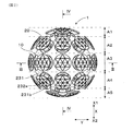
本例の刺激具1は、図1に示すように、コア10と、コア10の外表14に変位可能に配設された複数の変位部20と、を備え、各変位部20は変位に伴ってクリック感を発生するように構成されている。
なお、便宜的に、図1に示す側を上面側とし、反対側を下面側とする。そして、図2において、紙面上方向(図1における上面側の方向)をX1方向とし、紙面下側をX2方向とし、X1方向とX2方向とを合わせてX方向という。すなわち、図1は、図2においてX1方向側から見た図に相当する。また、図2において、X方向(X1方向及びX2方向)に垂直な紙面左右方向をY方向とする。また、図5において、コア10の径方向をZ方向とし、コア10の内側から外側に向かう方向を外方Z1とし、コア10の外側から内側に向かう方向を内方Z2とする。さらに、図5において、コア10の外表14の周方向をRとする。
(Example 1)
A stimulator according to an embodiment of the present example will be described with reference to FIGS.
As shown in FIG. 1, the stimulator 1 of the present example includes a core 10 and a plurality of displacement portions 20 that are displaceably disposed on the outer surface 14 of the core 10, and each displacement portion 20 is associated with displacement. To generate a click feeling.
For convenience, the side shown in FIG. 1 is the upper surface side, and the opposite side is the lower surface side. In FIG. 2, the upper direction on the paper surface (upper surface direction in FIG. 1) is the X1 direction, the lower surface is the X2 direction, and the X1 direction and the X2 direction are collectively referred to as the X direction. That is, FIG. 1 corresponds to the view seen from the X1 direction side in FIG. In FIG. 2, the left-right direction on the page perpendicular to the X direction (X1 direction and X2 direction) is defined as the Y direction. In FIG. 5, the radial direction of the core 10 is the Z direction, the direction from the inner side of the core 10 toward the outer side is the outer side Z1, and the direction from the outer side of the core 10 to the inner side is the inner side Z2. Further, in FIG. 5, the circumferential direction of the outer surface 14 of the core 10 is R.

以下、本例の刺激具1について、詳述する。
図4に示すように、コア10は、半球状の第1コア11及び第2コア12からなる。第1コア11及び第2コア12は互いの球状面を外側にして対向して設けられている第1コア11における第2コア12との対向面には複数の嵌合凹部11a(図3参照)が形成されているとともに、第2コア12における第1コア11との対向面には、嵌合凹部11aにそれぞれ嵌合する複数の嵌合凸部12a(図3参照)が形成されている。嵌合凹部11aに複数の嵌合凸部12aが嵌合されることにより、コア10は略球状に形成されている。コア10は中空状に形成されて中空部10aを有している。中空部10aには図3、図4に示すように円柱状の金属製の重り13が収容されている。刺激具1全体の重量は、重り13の重量を調整することにより適宜調整することができる。刺激具1全体の重量は、例えば90g〜130gとすることができ、更には105〜110gが好ましく、本例では105gである。
Hereinafter, the stimulator 1 of this example will be described in detail.
As shown in FIG. 4, the core 10 includes a hemispherical first core 11 and a second core 12. The first core 11 and the second core 12 are provided so as to face each other with their spherical surfaces on the outside. The first core 11 has a plurality of fitting recesses 11a (see FIG. 3) on the surface facing the second core 12. ) And a plurality of fitting convex portions 12a (see FIG. 3) that are fitted in the fitting concave portions 11a, respectively, are formed on the surface of the second core 12 facing the first core 11. . The core 10 is formed in a substantially spherical shape by fitting the plurality of fitting convex portions 12a into the fitting concave portion 11a. The core 10 is formed in a hollow shape and has a hollow portion 10a. As shown in FIGS. 3 and 4, a cylindrical metal weight 13 is accommodated in the hollow portion 10a. The weight of the stimulator 1 as a whole can be adjusted as appropriate by adjusting the weight of the weight 13. The total weight of the stimulator 1 can be, for example, 90 g to 130 g, more preferably 105 to 110 g, and 105 g in this example.

図1、図3に示すように、コア10の外表14には、複数の凹部15が形成されている。凹部15はそれぞれ有底のすり鉢状に形成されている。図3に示すように、凹部15の底部の中央には、コア10の中空部10aに連通する貫通孔15aが形成されている。   As shown in FIGS. 1 and 3, a plurality of recesses 15 are formed on the outer surface 14 of the core 10. The recesses 15 are each formed in a bottomed mortar shape. As shown in FIG. 3, a through hole 15 a that communicates with the hollow portion 10 a of the core 10 is formed at the center of the bottom of the recess 15.

コア10の外表は、図2に示すように、X1方向端部領域A1、X1方向中間領域A2、中央領域A3、X2方向中間領域A4及びX2方向端部領域A5に、それぞれ仮想的に区画されている。X1方向端部領域A1及びX2方向端部領域A5には、それぞれ3個の凹部15が形成されており、X1方向中間領域A2及びX2方向中間領域A4にはそれぞれ8個の凹部15が形成されている。また、中央領域A3には10個の凹部15が形成されている。各領域A1〜A5の個々の領域内において隣り合う凹部15の間隔は、等間隔であるが、各領域A1〜A5において他の領域との間で隣り合う凹部15の間隔は、等間隔になっていない。   As shown in FIG. 2, the outer surface of the core 10 is virtually divided into an X1 direction end region A1, an X1 direction intermediate region A2, a central region A3, an X2 direction intermediate region A4, and an X2 direction end region A5. ing. Three recesses 15 are formed in each of the end region A1 in the X1 direction and the end region A5 in the X2 direction, and eight recesses 15 are formed in each of the intermediate region A2 in the X1 direction and the intermediate region A4 in the X2 direction. ing. In addition, ten concave portions 15 are formed in the central region A3. The intervals between the recesses 15 adjacent to each other in each of the regions A1 to A5 are equal, but the intervals between the recesses 15 adjacent to other regions in each region A1 to A5 are equal. Not.

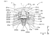
そして、各領域A1〜A5のそれぞれの凹部15に変位部20が設けられている。すなわち、本例では、変位部20は全体で32個設けられている。そして、図5に示す初期姿勢(すなわち、刺激具1の外部から変位部20に力が付与されていない状態)において、変位部20は、コア10の外表14からコア10の外方Z1へ突出している。変位部20は、外側表面21aを形成する頭部21と、該頭部21に取り付けられた軸状の脚部22と、コア10の外表14に取り付けられるとともに、脚部22をコア10の内方Z2及び外方Z1に向けて移動可能に保持する保持部23と、を備える。
各変位部20が変位する前の状態において、各変位部20の外側表面21aが球面に沿うように形成されている。当該球面の直径は50.0mm〜65.0mmとすることができ、本例では58.0mmである。
And the displacement part 20 is provided in each recessed part 15 of each area | region A1-A5. That is, in this example, 32 displacement portions 20 are provided as a whole. In the initial posture shown in FIG. 5 (that is, in a state in which no force is applied to the displacement portion 20 from the outside of the stimulator 1), the displacement portion 20 projects from the outer surface 14 of the core 10 to the outer side Z1 of the core 10. ing. The displacement portion 20 is attached to the head portion 21 forming the outer surface 21 a, the shaft-like leg portion 22 attached to the head portion 21, and the outer surface 14 of the core 10. And a holding portion 23 that is held so as to be movable toward the direction Z2 and the outside Z1.
In a state before each displacement part 20 is displaced, the outer surface 21a of each displacement part 20 is formed along the spherical surface. The spherical surface can have a diameter of 50.0 mm to 65.0 mm, and is 58.0 mm in this example.

頭部21は、図1に示すように、円盤状に形成されている。頭部21の直径は、例えば10.0mm〜20.0mmとすることができ、本例では14.2mmである。頭部21は真鍮製又は樹脂製とすることができる。頭部21が樹脂製である場合には、その表面には金属メッキを形成することができる。本例では、頭部21は樹脂製であって、その表面にクロムメッキが形成されている。各頭部21の重量は、例えば0.5g〜4.0gとすることができ、本例では1.0gである。図5に示すように、頭部21の外側表面21aは、コア10の外方(図5におけるZ1方向)に緩やかに膨出しているとともに、図1に示すように、複数の三角形の面を組み合わせたダイヤカットが施されている。なお、図5に示すように、当該複数の三角形の各面は、隣接する面となだらかにつながるように各面の縁部がわずかに曲面となっている。頭部21の外側表面21aと反対側には圧入凹部21bが形成されている。なお、外側表面21aの角部21dは面取りされて湾曲面となっている。角部21dは例えば、後述の接続軸221の軸Lを通る断面における形状が、曲率半径28.5mm〜28.7mmの曲線を成すように形成することができ、本例では、曲率半径28.5mmの曲線を成している。   The head 21 is formed in a disk shape as shown in FIG. The diameter of the head 21 can be set to 10.0 mm to 20.0 mm, for example, and is 14.2 mm in this example. The head 21 can be made of brass or resin. When the head 21 is made of resin, metal plating can be formed on the surface thereof. In this example, the head 21 is made of resin and has a chromium plating formed on the surface thereof. The weight of each head 21 can be set to, for example, 0.5 g to 4.0 g, and is 1.0 g in this example. As shown in FIG. 5, the outer surface 21a of the head 21 gently bulges outward (Z1 direction in FIG. 5) of the core 10, and as shown in FIG. Combined diamond cut is given. As shown in FIG. 5, each surface of the plurality of triangles has a slightly curved edge at each surface so as to be smoothly connected to an adjacent surface. A press-fit recess 21b is formed on the side of the head 21 opposite to the outer surface 21a. The corner 21d of the outer surface 21a is chamfered to form a curved surface. The corner 21d can be formed, for example, such that a shape in a cross section passing through the axis L of the connecting shaft 221 described later forms a curve with a curvature radius of 28.5 mm to 28.7 mm. It has a 5 mm curve.

図5に示すように、脚部22は、接続軸221と摺動板222とからなる。接続軸221は略円柱状を成しており、コア10の外方Z1の端部には縮径された縮径部221aが形成されている。接続軸221の軸Lは、初期姿勢(すなわち、頭部21が押圧されていない状態)ではコア10の径方向Zと一致している。縮径部221aが頭部21の圧入凹部21bに圧入されて、接続軸221と頭部21とが接合されている。接続軸221のコア10の内方Z2の端部には、壁面が部分球面を成す球状凹部221bが形成されているとともに、コア10の外周方向Rに環状に突出する環状リブ221cが形成されている。そして、摺動板222は円盤状を成しており、接続軸221に対向する面に球状に突出した球状突起222aが形成されている。当該球状突起222aの外径は接続軸221の球状凹部221bの径と略同一である。当該球状突起222aが接続軸221の球状凹部221bに嵌入されて、接続軸221が摺動板222に連結されている。そして、球状突起222aと球状凹部221bとによってボールジョイントが形成されており、摺動板222に対して接続軸221が傾斜することが許容されている。摺動板222において球状突起222aと反対側には、球面状に緩やかに膨出した膨出部222bが形成されている。   As shown in FIG. 5, the leg portion 22 includes a connecting shaft 221 and a sliding plate 222. The connecting shaft 221 has a substantially columnar shape, and a reduced diameter portion 221 a having a reduced diameter is formed at the end of the outer side Z <b> 1 of the core 10. The axis L of the connecting shaft 221 coincides with the radial direction Z of the core 10 in the initial posture (that is, the state where the head 21 is not pressed). The reduced diameter portion 221a is press-fitted into the press-fit recess 21b of the head portion 21, and the connection shaft 221 and the head portion 21 are joined. A spherical concave portion 221b whose wall surface forms a partial spherical surface is formed at the end of the inner Z2 of the core 10 of the connecting shaft 221, and an annular rib 221c that protrudes annularly in the outer peripheral direction R of the core 10 is formed. Yes. The sliding plate 222 has a disk shape, and a spherical protrusion 222 a that protrudes in a spherical shape is formed on the surface facing the connecting shaft 221. The outer diameter of the spherical protrusion 222 a is substantially the same as the diameter of the spherical recess 221 b of the connection shaft 221. The spherical protrusion 222 a is fitted into the spherical recess 221 b of the connection shaft 221, and the connection shaft 221 is coupled to the sliding plate 222. A ball joint is formed by the spherical protrusion 222 a and the spherical recess 221 b, and the connection shaft 221 is allowed to tilt with respect to the sliding plate 222. A bulging portion 222b that gently bulges in a spherical shape is formed on the side of the sliding plate 222 opposite to the spherical protrusion 222a.

保持部23は、第1筒状部材231と第2筒状部材232とからなる。第1筒状部材231は、その内周部が接続軸221の外形に沿って筒状に形成されているとともに、コア10の内方Z2側に、環状リブ221cの外形に沿う段差部231aを備える。当該第1筒状部材231の内側に接続軸221が挿通されるとともに、段差部231aによって環状リブ221cが係止されて、接続軸221が抜け止めされている。第1筒状部材231の外周部には周方向Rに突出した一対の係止突起部231bが形成されている。   The holding unit 23 includes a first cylindrical member 231 and a second cylindrical member 232. The first cylindrical member 231 has an inner peripheral portion formed in a cylindrical shape along the outer shape of the connecting shaft 221, and a step portion 231 a along the outer shape of the annular rib 221 c on the inner Z <b> 2 side of the core 10. Prepare. The connection shaft 221 is inserted inside the first cylindrical member 231, and the annular rib 221 c is locked by the step portion 231 a so that the connection shaft 221 is prevented from coming off. A pair of locking protrusions 231 b protruding in the circumferential direction R are formed on the outer peripheral portion of the first cylindrical member 231.

第2筒状部材232は内底部233を有する筒状に形成されているとともに、コア10の外方Z1側の端部には、外方Z1側に突出する一対の突出部232aが形成されている。図1、図5に示すように、一対の突出部232aには、その一部を切り欠いて形成された窓部232bが設けられている。一対の突出部232aは第1筒状部材231の外周に沿って立設されており、窓部232bに係止突起部231bが係止されることにより、第1筒状部材231が第2筒状部材232に固定されている。そして、第2筒状部材232の内周部は、摺動板222の外径と略同一の径を有する円筒状を成している。これにより、摺動板222は第2筒状部材232内側にZ方向に摺動可能に保持されている。   The second cylindrical member 232 is formed in a cylindrical shape having an inner bottom portion 233, and a pair of projecting portions 232a projecting toward the outer Z1 side are formed at the end portion of the core 10 on the outer Z1 side. Yes. As shown in FIGS. 1 and 5, the pair of projecting portions 232 a is provided with a window portion 232 b formed by cutting out a part thereof. The pair of projecting portions 232a are erected along the outer periphery of the first cylindrical member 231, and the first cylindrical member 231 is connected to the second tube by the locking projection 231b being locked to the window portion 232b. It is fixed to the member 232. The inner peripheral portion of the second cylindrical member 232 has a cylindrical shape having a diameter substantially the same as the outer diameter of the sliding plate 222. Accordingly, the sliding plate 222 is held inside the second cylindrical member 232 so as to be slidable in the Z direction.

第2筒状部材232におけるコア10の内方Z2の端部には、内方Z2側に突出する嵌入突起部232cが形成されている。嵌入突起部232cは略円柱状をなしており、凹部15の貫通孔15aの径と略同一の外径を有する。そして、嵌入突起部232cの先端は球状を成すとともに、拡径された球状係止部232dが設けられている。球状係止部232dには、スリット232eが形成されている。これにより、嵌入突起部232c(球状係止部232d)を貫通孔15aに圧入することにより、スリット232eが狭まるように球状係止部232dが弾性変形して貫通孔15aに挿通される。そして、球状係止部232dが貫通孔15aを圧入側と反対側に抜け出ることにより、スリット232eが広がるように弾性変形して貫通孔15aの縁に係止され、嵌入突起部232cが貫通孔15aに嵌入される。その結果、第2筒状部材232を凹部15内に係止されることとなる。なお、これに替えて、第2筒状部材232を凹部15内にネジ止めしても良い。   An insertion protrusion 232c that protrudes toward the inner Z2 side is formed at the end of the inner side Z2 of the core 10 in the second cylindrical member 232. The fitting protrusion 232 c has a substantially cylindrical shape and has an outer diameter that is substantially the same as the diameter of the through hole 15 a of the recess 15. And the front-end | tip of the insertion protrusion part 232c comprises spherical shape, and the spherical latching | locking part 232d expanded in diameter is provided. A slit 232e is formed in the spherical locking portion 232d. As a result, the fitting protrusion 232c (spherical locking portion 232d) is press-fitted into the through hole 15a, whereby the spherical locking portion 232d is elastically deformed and inserted into the through hole 15a so that the slit 232e is narrowed. Then, when the spherical locking portion 232d exits the through hole 15a to the side opposite to the press-fitting side, the slit 232e is elastically deformed so as to expand and is locked to the edge of the through hole 15a, and the fitting protrusion 232c is locked to the through hole 15a. Inserted. As a result, the second cylindrical member 232 is locked in the recess 15. Alternatively, the second cylindrical member 232 may be screwed into the recess 15.

第2筒状部材232の内底部233と摺動板222との間には、付勢部材としての円盤形のドーム形状を有する金属板からなる皿バネ24が介在されている。皿バネ24は、自然状態においては、その中央部24aが摺動板222側に突出するように緩やかに湾曲している。そして、皿バネ24の中央部24aは、摺動板222の膨出部222bに当接しているとともに、第1筒状部材231と第2筒状部材232とが組み付けられた状態において、膨出部222bから皿バネ24に向けて押圧力を受けており、皿バネ24はこれに対する反力によって膨出部222bをコア10の外方Z1側に付勢している。   A disc spring 24 made of a metal plate having a disk-like dome shape as an urging member is interposed between the inner bottom 233 of the second cylindrical member 232 and the sliding plate 222. In a natural state, the disc spring 24 is gently curved so that the central portion 24a protrudes toward the sliding plate 222 side. The central portion 24 a of the disc spring 24 is in contact with the bulging portion 222 b of the sliding plate 222 and bulges in a state where the first cylindrical member 231 and the second cylindrical member 232 are assembled. The disc spring 24 receives a pressing force from the portion 222b toward the disc spring 24, and the disc spring 24 biases the bulging portion 222b toward the outward Z1 side of the core 10 by a reaction force thereto.

図6に示すように、使用者によって頭部21がコア10の内方Z2側に押圧されると、頭部21に接続された接続軸221を介して摺動板222が内方Z2側に押圧されて、膨出部222bが皿バネ24の中央部24aを内方Z2側に押圧することとなる。そして、当該押圧力が皿バネ24の反転変形(飛び移り座屈)に要する押圧力の閾値を上回ると、中央部24aは内方Z2側に突出するように弾性変形して、皿バネ24の中央部24aが内方Z2側に反転変形することとなる。皿バネ24の反転変形に要する押圧力の閾値は、例えば1.0N〜6.0Nとすることができ、本例では、2.5Nとしている。そして、皿バネ24の中央部24aが反転変形することにより、押圧力に対する反力として摺動板222を外方Z1側に付勢していた付勢力が一時的に急激に低下することとなる。これにより、頭部21が内方Z2側に所定量変位することに伴って、使用者にクリック感(いわゆるタクティルフィーリング)を感じさせることができる。   As shown in FIG. 6, when the user presses the head 21 toward the inner side Z <b> 2 of the core 10, the sliding plate 222 moves toward the inner side Z <b> 2 via the connecting shaft 221 connected to the head 21. When pressed, the bulging portion 222b presses the central portion 24a of the disc spring 24 toward the inward Z2 side. When the pressing force exceeds the threshold value of the pressing force required for the reverse deformation (jumping buckling) of the disc spring 24, the central portion 24a is elastically deformed so as to protrude toward the inward Z2 side. The central portion 24a is inverted and deformed to the inner Z2 side. The threshold value of the pressing force required for the reverse deformation of the disc spring 24 can be set to 1.0 N to 6.0 N, for example, and is 2.5 N in this example. Then, when the central portion 24a of the disc spring 24 is reversely deformed, the urging force that has urged the sliding plate 222 toward the outward Z1 side as a reaction force against the pressing force temporarily temporarily decreases. . Accordingly, the user can feel a click feeling (so-called tactile feeling) as the head 21 is displaced by a predetermined amount toward the inward Z2 side.

上記頭部21が内方Z2側に変位する変位量(ストローク)は、適宜設定することができ、例えば、0.1mm〜2.0mm、好ましくは、0.1mm〜1.0mmとすることができ、本例では0.2mmである。   The amount of displacement (stroke) by which the head 21 is displaced inward Z2 can be set as appropriate, for example, 0.1 mm to 2.0 mm, preferably 0.1 mm to 1.0 mm. This is 0.2 mm in this example.

なお、当該ストロークを大きくしたい場合には、摺動板222と皿バネ24との間に、つる巻バネやゴム部材などの弾性部材を介在させることにより頭部21のストロークを大きくすることができる。この場合には、摺動板222と皿バネ24とを離隔させる方向に両者を付勢する当該弾性部材が頭部21の内方Z2側に変位に伴って圧縮変形することにより、摺動板222が皿バネ24を直接的に又は弾性部材を介して間接的に押圧するように構成することができる。そして、当該弾性部材の圧縮変形量を適宜設定することにより、頭部21のストロークを調整することができる。   When it is desired to increase the stroke, the stroke of the head 21 can be increased by interposing an elastic member such as a helical spring or a rubber member between the sliding plate 222 and the disc spring 24. . In this case, the elastic member that urges both the sliding plate 222 and the disc spring 24 in a direction to separate them compressively deforms toward the inward Z2 side of the head 21, and thereby the sliding plate 222 can be configured to press the disc spring 24 directly or indirectly through an elastic member. Then, the stroke of the head 21 can be adjusted by appropriately setting the amount of compressive deformation of the elastic member.

頭部21が内方Z2側に変位された後、上記押圧力を解除すると、皿バネ24からの付勢力により、頭部21は元の位置に復位する。そして、皿バネ24の中央部24aは反転状態から元の状態に戻るときに、摺動板222を外方Z1側に付勢する付勢力が一時的に急激に上昇する。これにより、頭部21が外方Z1側に復位することに伴って、使用者にクリック感を感じさせることができる。   When the pressing force is released after the head 21 is displaced inward Z2, the head 21 is returned to its original position by the biasing force from the disc spring 24. When the central portion 24a of the disc spring 24 returns from the inverted state to the original state, the urging force that urges the sliding plate 222 toward the outward Z1 side temporarily rises rapidly. Thereby, a user can be made to feel a click feeling in connection with the head 21 returning to the outward Z1 side.

さらに、付勢部材としての皿バネ24は、自然状態から反転変形する際及び反転状態から自然状態に戻るように再度反転変形する際に、当該再度の反転変形に起因する振動によって変形音が生じる。これにより、頭部21がコア10の内方Z2側へ変位する際及び頭部21がコア10の外方Z1側へ復位する際にクリック感とともに、クリック音を呈する。   Further, when the disc spring 24 as the urging member is reversely deformed from the natural state and when it is reversely deformed again so as to return from the reverse state to the natural state, a deformation sound is generated due to vibration caused by the reversal of the reverse state. . As a result, when the head 21 is displaced toward the inner Z2 side of the core 10 and when the head 21 is repositioned toward the outer Z1 side of the core 10, a click sound is presented together with a click feeling.

また、本例では、上述の如く、接続軸221と摺動板222とはボールジョイントにより連結されているため、図7に示すように、初期姿勢(図7の破線で示す状態)における脚部22の軸Lに対して接続軸221が傾斜することが許容されている。これにより、頭部21の縁部21cに内方Z2に向かう押圧力が付与された場合であっても、頭部21及び接続軸221は、コア10の周方向Rの内、押圧力が付与された側に傾斜した状態で内方Z2側に変位することができる。頭部21が傾斜していない状態から傾斜した状態となるときの縁部21cの周方向Rにおける変位量tは、例えば0.5mm〜1.5mmとすることができ、本例では0.8mmである。そして、隣り合う変位部20の頭部21が接触しないように、隣り合う変位部20の頭部21同士の距離は2.0mm以上確保されている。   In this example, as described above, since the connecting shaft 221 and the sliding plate 222 are coupled by the ball joint, as shown in FIG. 7, the leg portion in the initial posture (state shown by the broken line in FIG. 7). The connecting shaft 221 is allowed to tilt with respect to the 22 axes L. Thereby, even if it is a case where the pressing force which goes to the inner side Z2 is given to the edge 21c of the head 21, the head 21 and the connecting shaft 221 are given the pressing force in the circumferential direction R of the core 10. It can be displaced to the inner Z2 side in a state inclined to the formed side. The displacement amount t in the circumferential direction R of the edge portion 21c when the head portion 21 is inclined from the non-inclined state can be set to, for example, 0.5 mm to 1.5 mm, and in this example, 0.8 mm. It is. And the distance of the heads 21 of the adjacent displacement part 20 is ensured 2.0 mm or more so that the head 21 of the adjacent displacement part 20 may not contact.

また、接続軸221と摺動板222とはボールジョイントにより連結されているため、頭部21は摺動板222及び保持部23に対して、接続軸221の軸Lを中心に回転可能となっている。   Further, since the connecting shaft 221 and the sliding plate 222 are coupled by a ball joint, the head 21 can rotate around the axis L of the connecting shaft 221 with respect to the sliding plate 222 and the holding portion 23. ing.

次に、本例の刺激具における作用効果について、詳述する。
上記刺激具1によれば、コア10の外表14に配設された複数の変位部20が変位することに伴ってクリック感を発生される。使用者は当該クリック感を得ることにより、変位部20を確実に変位させたことを認識することができる。そして、変位部20を繰り返し変位させたり、複数の変位部20を一斉に変位させたりすることによって多数のクリック感が得られるとともに、当該多数のクリック感が相俟って楽しさと心地よい体感が使用者にもたらされることとなる。これにより、使用者に刺激具1を繰り返し使用することを促すことができる。そして、使用者は刺激具1を繰り返し使用することにより、掌や指が効果的にマッサージされることとなる。なお、刺激具1を首筋、肩、背中、四肢などの様々な部分に繰り返し押し当てて体の様々な部分に繰り返ししてもよい。この場合には、首筋、肩、背中、四肢などの体の様々な部分が効果的にマッサージされることとなる。
Next, the effects of the stimulator of this example will be described in detail.
According to the stimulator 1, a click feeling is generated as the plurality of displacement portions 20 disposed on the outer surface 14 of the core 10 are displaced. The user can recognize that the displacement portion 20 has been reliably displaced by obtaining the click feeling. Further, by repeatedly displacing the displacement part 20 or displacing the plurality of displacement parts 20 at the same time, a large number of click feelings can be obtained, and a combination of the large number of click feelings provides a pleasant and pleasant experience. It will be brought to the person. Thereby, it is possible to prompt the user to repeatedly use the stimulator 1. And a user will massage a palm and a finger effectively by using the stimulator 1 repeatedly. Note that the stimulator 1 may be repeatedly pressed against various parts of the body such as the neck, shoulders, back, and extremities and repeated on various parts of the body. In this case, various parts of the body such as the neck, shoulders, back, and limbs are effectively massaged.

さらに、使用者は掌や指によって変位部20を繰り返し変位させることにより、掌や指を介してクリック感や押圧感を繰り返し知覚することとなる。そのため、掌や指を介して使用者の脳に繰り返し刺激を与えることができる。その結果、使用者の脳の活性化を促す効果が奏される。   Furthermore, the user repeatedly perceives a click feeling and a pressing feeling through the palm and fingers by repeatedly displacing the displacement portion 20 with the palm and fingers. Therefore, the user's brain can be repeatedly stimulated through the palm and fingers. As a result, there is an effect of promoting the activation of the user's brain.

上記各変位部20は、初期姿勢を維持する方向(本例ではZ1方向)に付勢されているとともに、付勢力に抗して変位可能に構成されている。これにより、変位部20は、付勢力に抗して付与されていた力が解除されると、初期姿勢に復位することとなる。これにより、使用者は変位させた変位部20を復位させるには、変位部20に付与していた力を解除するだけでよいため、変位部20を復位させる手間がかからず、繰り返し使用する際の使い勝手が良い。そして、使用者は、変位部20をリズミカルにテンポよく繰り返し変位させることができる。これにより、当該変位に応じてリズミカルで心地よいテンポのクリック感を連続的に体感することができ、繰り返し使用することによる楽しさと心地よい体感が一層向上することとなる。また、リズミカルで心地よいテンポのクリック感が得られることにより、使用者の脳の活性化を一層促す効果を奏する。   Each of the displacement parts 20 is urged in a direction in which the initial posture is maintained (Z1 direction in this example), and is configured to be able to be displaced against the urging force. As a result, when the force applied against the urging force is released, the displacement unit 20 returns to the initial posture. Thus, since the user only has to release the force applied to the displacement portion 20 in order to restore the displaced displacement portion 20, the user does not need to reposition the displacement portion 20 and repeatedly uses it. Easy to use. And the user can displace the displacement part 20 repeatedly rhythmically with sufficient tempo. Thereby, it is possible to continuously experience a rhythmical and comfortable tempo click feeling according to the displacement, and to improve the enjoyment and comfortable feeling by repeatedly using. In addition, the rhythmical and comfortable click feeling of the tempo can be obtained, so that the user's brain is further activated.

変位部20は、上記付勢力により初期姿勢に復位することに伴ってクリック感を発生させるように構成されている。これにより、使用者は、変位部20を変位させたときのみならず、変位部20が復位するときにもクリック感が得られることとなる。すなわち、使用者は一つの変位部20の変位と復位により、クリック感が二回得られることとなる。これにより、変位部20をさらにリズミカルにテンポよく繰り返し変位させることができるとともに、当該変位に応じてリズミカルで心地よいテンポのクリック感を一層連続的に体感することができる。その結果、繰り返し使用することによる楽しさと心地よい体感を一層向上することができる。また、当該クリック感を掌や指を介して体感することにより、使用者の脳の活性化を一層促す効果をさらに得ることができる。   The displacement unit 20 is configured to generate a click feeling as it is restored to the initial posture by the urging force. Thereby, the user can obtain a click feeling not only when the displacement portion 20 is displaced but also when the displacement portion 20 is restored. That is, the user can obtain a click feeling twice by the displacement and the repositioning of one displacement portion 20. Accordingly, the displacement unit 20 can be displaced more rhythmically and repeatedly at a tempo, and a rhythmical and comfortable tempo click feeling can be experienced more continuously according to the displacement. As a result, it is possible to further improve the enjoyment and pleasant experience by repeated use. Further, by experiencing the click feeling through a palm or a finger, an effect of further promoting activation of the user's brain can be further obtained.

また、各変位部20は、外側表面21aを形成する頭部21と、該頭部21aに取り付けられた軸状の脚部22と、コア10の外表14に取り付けられるとともに、脚部22をコア10の内方Z2及び外方Z1に向けて移動可能に保持する保持部23と、を備える。これにより、変位部20の頭部21をコア10の内方Z2及び外方Z1に向けて移動させることができる。そのため、頭部21を押し込むように変位させることができる。その結果、使用者は変位部20(頭部21)を変位させたことを容易に認識することができる。   Each displacement portion 20 is attached to a head portion 21 forming an outer surface 21a, an axial leg portion 22 attached to the head portion 21a, and an outer surface 14 of the core 10, and the leg portion 22 is attached to the core. And a holding portion 23 that holds the inner side Z2 and the outer side Z1 in a movable manner. Thereby, the head 21 of the displacement part 20 can be moved toward the inner side Z2 and the outer side Z1 of the core 10. Therefore, the head 21 can be displaced so as to be pushed in. As a result, the user can easily recognize that the displacement unit 20 (head 21) has been displaced.

また、本例では、頭部21は、円盤状に形成されている。これにより、頭部21を掌や指で押圧しやすくなり、使い勝手が向上する。また、頭部21を尖形に形成する場合に比べて、変位部21と掌や指との当接面積を広く確保しやすいため、使用者の掌や指に対する刺激が適度に和らげられることとなり、繰り返し連続的に使用する場合にも使用者の負担が軽減される。さらに、使用者は頭部21からの刺激を点ではなく面で受けることとなるため、心地よい体感を得ることができる。   Moreover, in this example, the head 21 is formed in a disk shape. Thereby, it becomes easy to press the head 21 with a palm or a finger, and usability improves. Further, since the contact area between the displacement portion 21 and the palm or finger is easy to ensure compared to the case where the head 21 is formed in a pointed shape, the user's palm and finger stimulation can be moderated moderately. The burden on the user is reduced even when used repeatedly and continuously. Furthermore, since the user receives the stimulation from the head 21 not by the point but by the surface, the user can obtain a comfortable body sensation.

変位部20は、頭部21が図5に示す初期姿勢における脚部22の軸Lに対して傾斜するように変位可能に構成されている。これにより、様々な方向から変位部20を変位させることができるため、掌や指等により変位部20を変位させやすくなり、使用感を向上することができる。   The displacement portion 20 is configured to be displaceable so that the head portion 21 is inclined with respect to the axis L of the leg portion 22 in the initial posture shown in FIG. Thereby, since the displacement part 20 can be displaced from various directions, it becomes easy to displace the displacement part 20 with a palm, a finger, etc., and a usability | use_condition can be improved.

また、頭部21は、保持部23に対して回転可能に設けられている。これにより、様々な方向から力を付与して変位部を変位させる際に当該力が付与された方向に応じて頭部21を回転させることができるため、当該変位時に使用者が引っ掛かりを感じることが低減される。その結果、使用感の更なる向上が図られる。   The head 21 is provided so as to be rotatable with respect to the holding unit 23. Accordingly, when the force is applied from various directions to displace the displacement portion, the head 21 can be rotated in accordance with the direction in which the force is applied, so that the user feels a catch at the time of the displacement. Is reduced. As a result, the usability can be further improved.

本例では、変位部20は、上記変位に伴ってクリック音を発生するように構成されている。これにより、変位部20の変位によるクリック感をより強く認識させることができる。これにより、使用者は変位部20を確実に変位させたこと認識できる。その結果、変位部20を繰り返し変位させることによる楽しさと心地よい体感が一層向上し、使用者に刺激具1を繰り返し使用することをさらに促すことができる。   In this example, the displacement part 20 is comprised so that a click sound may be generated with the said displacement. Thereby, the click feeling by the displacement of the displacement part 20 can be recognized more strongly. Thereby, the user can recognize that the displacement part 20 was displaced reliably. As a result, the joy and pleasant feeling by repeatedly displacing the displacement portion 20 are further improved, and the user can be further encouraged to repeatedly use the stimulator 1.

本例では、保持部20には、脚部22をコア10の外方Z1に向けて付勢する付勢部材(皿バネ24)が備えられている。これにより、付勢部材24による付勢力を受けてコア10の内方Z2に変位した変位部20は、押圧が解除されることによって、確実に復位されることとなる。その結果、使用者は繰り返し使用する際に変位した変位部20を復位させる手間がかからないため、使い勝手が良い。また、繰り返し使用する際の使用感が向上する。   In the present example, the holding portion 20 is provided with a biasing member (a disc spring 24) that biases the leg portion 22 toward the outer side Z1 of the core 10. Thereby, the displacement part 20 which received the urging | biasing force by the urging | biasing member 24 and was displaced to the inward Z2 of the core 10 will be reliably restored | relocated by releasing a press. As a result, the user does not have the trouble of restoring the displaced portion 20 that has been displaced when repeatedly used. Moreover, the feeling of use at the time of using repeatedly improves.

本例の付勢部材24は弾性体からなっている。これにより、弾性体の弾性力により付勢部材24の付勢力を簡易な構成で容易に得ることができるため、構成の簡略化を図ることができる。そして、本例では、付勢部材は弾性体である皿バネ24からなる。これにより、付勢部材としての皿バネ24を安価な材料で形成することができ、コスト面で有利となる。また、簡易な構成とすることができるため、刺激具1の組み立て作業性が向上する。   The biasing member 24 of this example is made of an elastic body. Thereby, since the urging force of the urging member 24 can be easily obtained with a simple configuration by the elastic force of the elastic body, the configuration can be simplified. In this example, the urging member includes a disc spring 24 that is an elastic body. Thereby, the disc spring 24 as an urging member can be formed of an inexpensive material, which is advantageous in terms of cost. Moreover, since it can be set as a simple structure, the assembly workability | operativity of the stimulator 1 improves.

なお、本例では、付勢部材として皿バネ24を使用したがこれに限らず、板バネ、コイルばね、つる巻ばね、ゴムなどの弾性体を用いることができる。また、弾性体以外にも、変位部20を図5に示す初期姿勢を維持する方向に付勢することが可能であれば、付勢部材として使用してもよい。   In this example, the disc spring 24 is used as the biasing member. However, the present invention is not limited to this, and an elastic body such as a plate spring, a coil spring, a helical spring, or rubber can be used. In addition to the elastic body, as long as it is possible to bias the displacement portion 20 in the direction of maintaining the initial posture shown in FIG. 5, it may be used as a biasing member.

本例では、上記クリック音は、変位部20を変位させて皿バネ24を反転変形させたときに生じる皿バネ24の変形音からなる。これにより、付勢部材である皿バネ24によってクリック音を発生させることができるため、クリック音を得るために別途部材を用意する必要がなく、構成の簡略化を図ることができる。   In this example, the click sound includes a deformed sound of the disc spring 24 that is generated when the disc spring 24 is inverted and deformed by displacing the displacement portion 20. Thereby, since the click sound can be generated by the disc spring 24 as the biasing member, it is not necessary to prepare a separate member for obtaining the click sound, and the configuration can be simplified.

なお、変形例として、別部材として備えられるクリック音発生手段により上記クリック音を発生させてもよい。クリック音発生手段としては、特に限定されず、種々の構成を採用できる。例えば、クリック音発生手段として、図5に示す第2筒状部材232は内底部233と、付勢部材(皿バネ24)との間に金属板を介在させるとともに、図6に示すように、皿バネ24が反転変形したときに、皿バネ24の中央部24aが当該金属板に衝突するように構成したものを採用することができる。この場合には、中央部24aが当該金属板に衝突することにより生じる衝突音をクリック音として利用することができる。   As a modification, the click sound may be generated by click sound generating means provided as a separate member. The click sound generating means is not particularly limited, and various configurations can be adopted. For example, as a click sound generating means, the second cylindrical member 232 shown in FIG. 5 has a metal plate interposed between the inner bottom portion 233 and the biasing member (disc spring 24), and as shown in FIG. A configuration in which the central portion 24a of the disc spring 24 collides with the metal plate when the disc spring 24 is reversely deformed can be employed. In this case, a collision sound generated when the central portion 24a collides with the metal plate can be used as a click sound.

本例では、変位部20は、コア10の外表14からコア10の外方Z1へ突出している。そして、変位部20の頭部21における外側表面21aは、外表14における凹部15が形成されていない部分よりも、コア10の外方Z1に位置している。コア10の外表14における凹部15が形成されていない部分と変位部20の外側表面21aとが面一となるように構成した場合や、変位部20の外側表面21aが外表14における凹部15が形成されていない部分よりもコア10の内方Z2に位置するように構成した場合には、使用者が当該刺激具を掌握したときに、掌や指が外側表面21aのみならず、外表14における凹部15が形成されていない部分にも触れることとなるため、変位部20を押圧する際の体感が低下する。また、使用者が当該刺激具を掌握したときに、掌や指が外側表面21aと外表14における凹部15が形成されていない部分に触れるため、繰り返し連続的に使用すると当該刺激具と掌との間に熱がこもることにより、掌や指に汗をかきやすくなる。これによっても使用者の体感を低下させる。しかし、本例では、上述のごとく構成することにより、使用者が刺激具1を掌握したときに、掌や指を外表14における凹部15が形成されていない部分に触れさせることなく、変位部20を確実に当接させることができるため、変位部20を押圧する際の体感が一層向上する。また、使用者が刺激具1を掌握したときに掌や指が外表14における凹部15が形成されていない部分に触れず、掌や指と外表14における凹部15が形成されていない部分との間の空間が維持されるため、繰り返し連続的に使用しても刺激具1と掌との間に熱がこもりにくい。その結果、掌や指に汗をかくことが抑制されるため、使用者に繰り返し連続的に使用することを一層促すことができる。   In this example, the displacement part 20 protrudes from the outer surface 14 of the core 10 to the outer side Z <b> 1 of the core 10. And the outer surface 21a in the head 21 of the displacement part 20 is located in the outer side Z1 of the core 10 rather than the part in which the recessed part 15 in the outer surface 14 is not formed. When the portion where the concave portion 15 is not formed on the outer surface 14 of the core 10 and the outer surface 21a of the displacement portion 20 are configured to be flush with each other, or the outer surface 21a of the displacement portion 20 forms the concave portion 15 on the outer surface 14. In the case where it is configured to be located in the inner Z2 of the core 10 rather than the portion that is not formed, when the user grasps the stimulator, the palm and fingers are not only the outer surface 21a, but also the recesses in the outer surface 14 Since the part in which 15 is not formed is also touched, the feeling at the time of pressing the displacement part 20 falls. Further, when the user grasps the stimulator, the palm and fingers touch the outer surface 21a and the portion of the outer surface 14 where the recess 15 is not formed. The heat builds up between them, making it easier to sweat the palms and fingers. This also reduces the user experience. However, in this example, by configuring as described above, when the user grasps the stimulator 1, the displacement portion 20 is not brought into contact with a portion of the outer surface 14 where the concave portion 15 is not formed. Can be surely brought into contact with each other, so that the feeling when pressing the displacement portion 20 is further improved. Further, when the user grasps the stimulator 1, the palm or finger does not touch the portion where the concave portion 15 is not formed on the outer surface 14, and between the palm or finger and the portion where the concave portion 15 is not formed on the outer surface 14. Therefore, even if it is used repeatedly and continuously, it is difficult for heat to be trapped between the stimulator 1 and the palm. As a result, sweating of the palm and fingers is suppressed, and the user can be further encouraged to use it repeatedly and continuously.

本例では、コア10の外形は球状となっている。これにより、使用者が刺激具1全体を掌握しやすくなり、使用感が向上する。また、本例では、刺激具1の外表(変位部20の外側表面21a)は、直径57.4mmの球面に沿って形成されている。そして、押圧された状態では、最小で直径57.0mmとなる。そのため、刺激具1は掌に収まりのいい形状に形成されているため、使用感が一層向上する。また、繰り返し連続的に使用しても過度に疲れることが抑制されるため、使用者に繰り返し連続的に使用することを一層促すことができる。   In this example, the outer shape of the core 10 is spherical. Thereby, it becomes easy for a user to grasp the stimulator 1 whole, and a feeling of use improves. Moreover, in this example, the outer surface (outer surface 21a of the displacement part 20) of the stimulator 1 is formed along a spherical surface having a diameter of 57.4 mm. In the pressed state, the diameter is 57.0 mm at the minimum. Therefore, since the stimulator 1 is formed in a shape that fits in the palm, the feeling of use is further improved. Moreover, since it is suppressed that it gets tired excessively even if it uses repeatedly repeatedly, it can further encourage a user to use it repeatedly repeatedly.

なお、コア10の外形を、直線状又は湾曲状の棒形状にしてもよい。例えば、コア10を把持可能なハンドル状に形成することができる。この場合にも、刺激具1を掌握しやすくなるため、使用感が向上する。   The outer shape of the core 10 may be a linear or curved rod shape. For example, the core 10 can be formed in a handle shape that can be gripped. Also in this case, since the stimulator 1 can be easily grasped, the usability is improved.

また、刺激具1の重量は90g〜130gとすることができ、更には105g〜110gが好ましく、本例では105gである。これにより、使用者に適度な重さを感じさせて高級感を与えることができるとともに、過剰に重くなることが防止されて、繰り返し連続的に使用する場合でも使用者に過度な負担を課すことが防止される。   Moreover, the weight of the stimulator 1 can be 90 g to 130 g, more preferably 105 g to 110 g, and 105 g in this example. As a result, it is possible to give the user a moderate weight and give a sense of quality, and it is prevented from becoming excessively heavy, and even when used repeatedly and repeatedly, it places an excessive burden on the user. Is prevented.

頭部21の材質は、真鍮、鉄、アルミなどの金属、ABS樹脂、PC樹脂などの合成樹脂、セラミックス、木材、石などを採用することができる。中でも金属製であることが好ましく、本例では真鍮製としている。頭部21を金属製とすることにより、頭部21が適度な重量を有することとなるため、頭部21を押圧する際に使用者に適度な重量感を与えて、高級感を高めることができる。また、一般的に金属は樹脂等に比べて熱伝導性が高いため、掌や指の熱が頭部21に伝播されやすいことから、掌や指の熱によって頭部21が容易に温められることとなる。そして、頭部21が温められた状態で繰り返し使用することにより、掌や指の血行を促進することができる。   The material of the head 21 may be a metal such as brass, iron, or aluminum, a synthetic resin such as ABS resin or PC resin, ceramics, wood, or stone. Of these, metal is preferable, and brass is used in this example. When the head 21 is made of metal, the head 21 has an appropriate weight, so that when the head 21 is pressed, the user is given an appropriate weight feeling to enhance a sense of quality. it can. In general, since metal has higher thermal conductivity than resin or the like, the heat of the palm or finger is easily transmitted to the head 21, so that the head 21 can be easily warmed by the heat of the palm or finger. It becomes. And by repeatedly using the head 21 in a warmed state, blood circulation of the palm and fingers can be promoted.

本例では、変位部20は、図2に示すように、刺激具1の各領域A1〜A5の上面側から下面側に向かって、3個、8個、10個、8個、3個の順で合計32個配設されている。そして、各領域A1〜A5間において、変位部20は等間隔に配列していない。これにより、刺激具1を握る位置によって、肌に当接する変位部20の位置が変化することとなる。その結果、掌や指への刺激効果を高めることができる。また、刺激具1を握る位置を適宜変えつつ使用することにより、飽きることなく繰り返し使用することができる。その結果、繰り返し使用することによる楽しさと心地よい体感を一層向上させて、使用者に繰り返し連続的に使用することを促すことができる。   In this example, as shown in FIG. 2, the displacement portion 20 includes three, eight, ten, eight, three pieces from the upper surface side to the lower surface side of each region A1 to A5 of the stimulator 1. A total of 32 are arranged in order. And the displacement part 20 is not arranged at equal intervals between each area | region A1-A5. Thereby, the position of the displacement part 20 which contact | abuts skin changes with the position which grips the stimulator 1. FIG. As a result, the stimulating effect on the palm and fingers can be enhanced. Moreover, it can be used repeatedly without getting tired by using changing the position which holds the stimulator 1 suitably. As a result, it is possible to further improve the enjoyment and pleasant experience of repeated use, and to encourage the user to use it repeatedly and continuously.

また、本例の変位部20の脚部22及び保持部23の代わりに、タクトスイッチやシーソー型スイッチなどのスイッチ機構を採用することができる。例えば、図8に示す変形例では、脚部22及び保持部23の代わりに、タクトスイッチ25を使用することができる。タクトスイッチ25として、皿バネなどの反転板を備えるメカニカル接点タイプ(反転型金属接点タイプ)であるタクティルプッシュスイッチを採用することができ、例えば、アルプス電気株式会社製のSKHHシリーズ(SKHHAL、SKHHAQ、SKHHCQ、SKHHCR)を採用することができる。タクトスイッチ25は、脚部としてのプランジャ252、保持部としてのケース253、付勢部材として皿バネ24を備える。この場合も、本例の場合と同様に、頭部21がコア10の内方Z2側に押圧されることにより、頭部21とともにプランジャ252が内方Z2に変位する。これにより、プランジャ252の内方Z2側の先端部が皿バネ24を押圧して、皿バネ24を反転変形させ、クリック感及びクリック音を呈する。
なお、タクトスイッチ25には接続端子254が備えられるが、本変形例では、他の部材とは電気的には接続されていない。したがって、プランジャ252を押圧しても、タクトスイッチ25の接点255は何ら電気的に接続されるものではない。なお、両者を電気的に接続する場合は、タクトスイッチ25を温熱や通電、音等の機能を制御するスイッチとして用いても良い。
Moreover, instead of the leg part 22 and the holding part 23 of the displacement part 20 of this example, switch mechanisms, such as a tact switch and a seesaw type switch, are employable. For example, in the modification shown in FIG. 8, the tact switch 25 can be used instead of the leg portion 22 and the holding portion 23. As the tact switch 25, a tactile push switch that is a mechanical contact type (reversed metal contact type) having a reversing plate such as a disc spring can be adopted. For example, the SKHH series (SKHHAL, SKHHAQ manufactured by Alps Electric Co., Ltd.) , SKHHCQ, SKHHCR) can be employed. The tact switch 25 includes a plunger 252 as a leg portion, a case 253 as a holding portion, and a disc spring 24 as a biasing member. Also in this case, as in the case of the present example, the head 21 is pressed toward the inner Z2 side of the core 10, whereby the plunger 252 is displaced inward Z2 together with the head 21. As a result, the distal end portion of the plunger 252 on the inner Z2 side presses the disc spring 24 to reversely deform the disc spring 24, thereby providing a click feeling and a click sound.
The tact switch 25 is provided with a connection terminal 254, but in the present modification, it is not electrically connected to other members. Therefore, even if the plunger 252 is pressed, the contact 255 of the tact switch 25 is not electrically connected at all. When both are electrically connected, the tact switch 25 may be used as a switch for controlling functions such as heat, energization, and sound.

また、上記タクトスイッチ25に替えて、皿バネとアクチュエータとを備え、頭部の押下によりアクチュエータを介して皿バネが押圧されるアクチュエータ方式メカニカル接点タイプのタクトスイッチを使用してもよい。また、付勢部材として、金属板からなる皿バネ24に替えて、ゴム製材料からなるカップ状部材を備えるエラスティック接点タイプのタクトスイッチを使用してもよい。   Instead of the tact switch 25, an actuator-type mechanical contact type tact switch that includes a disc spring and an actuator and that presses the disc spring through the actuator when the head is pressed may be used. Further, instead of the disc spring 24 made of a metal plate, an elastic contact type tact switch having a cup-like member made of a rubber material may be used as the urging member.

また、タクトスイッチに替えて、シーソー型のスイッチを使用してもよい。また、本例では、変位部20の変位方向は、コア10の内方Z2及び外方Z1としたが、これに限らない。例えば、変位部20がコア10の周方向Rに変位することに伴ってクリック感を発生させるように構成してもよい。   Further, a seesaw type switch may be used instead of the tact switch. Moreover, in this example, although the displacement direction of the displacement part 20 was set to the inner side Z2 and the outer side Z1 of the core 10, it is not restricted to this. For example, you may comprise so that a click feeling may be generated in connection with the displacement part 20 moving to the circumferential direction R of the core 10. FIG.

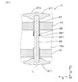
本例では、変位部20の接続軸26の一端のみに頭部21が接続されていることとしたが、これに替えて、図9に示すように、棒状の接続軸26の一端に頭部211が設けられ、他端に頭部212が設けられていてもよい。なお、この変形例ではコア10は筒状に形成されている。そして、接続軸26は、コア10の長手方向に直交する方向にコア10を貫通している。接続軸26の軸L方向の中間部には、断面三角形状に突出したリブ261が形成されている。そして、接続軸26は、コア10に嵌装されたブッシュ状の保持部27に挿通されている。保持部27のコア10内方の端部には付勢部材としての板バネ28が設けられている。板バネ28の先端はクランク状に屈曲されてクランク部281が形成されており、当該クランク部281が接続軸26の周面を付勢している。図9に示す状態では、リブ261はクランク部281よりも頭部211に近い側に位置している。   In this example, the head 21 is connected to only one end of the connecting shaft 26 of the displacement portion 20, but instead, as shown in FIG. 9, the head is connected to one end of the rod-shaped connecting shaft 26. 211 may be provided, and a head 212 may be provided at the other end. In this modification, the core 10 is formed in a cylindrical shape. The connecting shaft 26 penetrates the core 10 in a direction orthogonal to the longitudinal direction of the core 10. A rib 261 protruding in a triangular shape in cross section is formed at an intermediate portion in the axis L direction of the connecting shaft 26. The connection shaft 26 is inserted through a bush-shaped holding portion 27 fitted to the core 10. A leaf spring 28 as an urging member is provided at the inner end of the core 10 of the holding portion 27. The tip of the leaf spring 28 is bent in a crank shape to form a crank portion 281, and the crank portion 281 biases the peripheral surface of the connecting shaft 26. In the state shown in FIG. 9, the rib 261 is located closer to the head 211 than the crank portion 281.

紙面上側の頭部211が紙面下側に押圧されると、接続軸26が下方に移動するのに伴って、リブ261が板バネ28のクランク部281を押し上げる。そして、さらに接続軸26が下方に移動すると、リブ261は下方に向かってクランク部281を潜り抜ける。クランク部281は接続軸26の周面を付勢しているため、頭部211が紙面下側に変位して、リブ261がクランク部281を潜り抜けたときに、クリック感が得られることとなる。
その後、頭部212が紙面上側に押圧されると、リブ261は板バネ28のクランク部281を再度押し上げ、リブ261は上方に向かってクランク部281を潜り抜ける。これにより、頭部212が紙面上側に変位して、リブ261がクランク部281を潜り抜けたときに、クリック感が得られることとなる。
When the head 211 on the upper side of the paper is pressed downward on the paper, the rib 261 pushes up the crank portion 281 of the leaf spring 28 as the connecting shaft 26 moves downward. When the connecting shaft 26 further moves downward, the rib 261 passes through the crank portion 281 downward. Since the crank portion 281 urges the peripheral surface of the connecting shaft 26, a click feeling can be obtained when the head 211 is displaced downward in the drawing and the rib 261 passes through the crank portion 281. Become.
Thereafter, when the head portion 212 is pressed upward, the rib 261 pushes up the crank portion 281 of the leaf spring 28 again, and the rib 261 passes through the crank portion 281 upward. Thereby, when the head 212 is displaced to the upper side of the drawing and the rib 261 passes through the crank portion 281, a click feeling is obtained.

また、図9に示す付勢部材としての板バネ28に替えて、スプリング及びスチールボールを備えるスライドスイッチの構成を採用してもよい。この場合には、接続軸26の側面に窪みを形成するとともに、スプリングがスチールボールを接続軸26の側面に付勢している。そして、頭部211が紙面下側に押圧されて接続軸26が下方に移動するのに伴って、接続軸26の側面に付勢されていたスチールボールが上記窪みに嵌りこむことにより、クリック感が得られる。また、接続軸26が上方に移動するのに伴って、上記窪みに嵌り込んでいたスチールボールがスプリングの付勢力に抗して上記窪みから這い上がることによってもクリック感が得られる。   Further, instead of the leaf spring 28 as the urging member shown in FIG. 9, a configuration of a slide switch including a spring and a steel ball may be adopted. In this case, a recess is formed on the side surface of the connection shaft 26, and the spring urges the steel ball toward the side surface of the connection shaft 26. Then, as the head 211 is pressed down on the paper surface and the connecting shaft 26 moves downward, the steel ball urged to the side surface of the connecting shaft 26 is fitted into the depression, thereby causing a click feeling. Is obtained. In addition, as the connecting shaft 26 moves upward, the click feeling can be obtained also when the steel ball fitted in the depression rises from the depression against the urging force of the spring.

以上のごとく、本例によれば、使用者に楽しさと心地よい体感をもたらして、使用者に繰り返し使用することを促すことができる刺激具1を提供することができる。   As described above, according to this example, it is possible to provide the stimulator 1 that can provide a user with a pleasant and pleasant experience and can prompt the user to repeatedly use the device.

(脳波試験)
実施例1の刺激具1による脳の活性化について、以下の試験を行った。
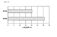
刺激具1の使用前及び使用後における使用者の脳波を計測し、使用前後における脳波を比較した。まず、ドライ電極式脳波計(Intercross社製、ミニチュアDAQターミナルIntercross-410)を、閉眼、座位の状態における使用者の頭頂部に取り付けて、刺激具1の使用前及び使用後のそれぞれにおいて脳波を計測した。そして、得られた脳波の周波数を分析して、α波(周波数8〜13Hz)とβ波(周波数13〜30Hz)を抽出した。その後、β波に対するα波の強度比(α/β×100)をα波の出現率(%)として算出した。被験者は41歳〜50歳の男女の合計10人とし、全被験者のα波出現率(%)の平均値を図10に示した。
(EEG test)
The following tests were performed on brain activation by the stimulator 1 of Example 1.
The brain waves of the user before and after using the stimulator 1 were measured, and the brain waves before and after use were compared. First, attach a dry electrode type electroencephalograph (Intercross, Miniature DAQ terminal Intercross-410) to the top of the user's head in a closed eye, sitting position, and the electroencephalogram before and after using the stimulator 1 respectively. Measured. And the frequency of the obtained electroencephalogram was analyzed, and alpha wave (frequency 8-13 Hz) and beta wave (frequency 13-30 Hz) were extracted. Thereafter, the intensity ratio of α waves to β waves (α / β × 100) was calculated as the appearance rate (%) of α waves. The test subjects were a total of 10 men and women between the ages of 41 and 50, and the average value of the α wave appearance rate (%) of all subjects is shown in FIG.

なお、α波は、安静、覚醒した状態(精神的活動が低下した状態)においてより多く観察され、視覚刺激時、運動時、暗算などの精神活動時、緊張時、睡眠時には減少することが知られている。また、β波は、能動的で活発な思考や集中時に観察されることが知られている。   It is known that α waves are more observed in resting and awakened states (states in which mental activity is reduced) and decrease during visual stimulation, exercise, mental activities such as mental arithmetic, tension, and sleep. It has been. In addition, it is known that β waves are observed during active and active thinking and concentration.

図10に示すように、刺激具1の使用前における平均α波出現率(%)は約20.5%であったのに対して、刺激具1の使用後における平均α波出現率(%)は約31.0%であった。すなわち、刺激具1の使用により、平均α波出現率(%)が約10.5%上昇したことが確認された。また、図示しないが、上記被験者の中には、刺激具1の使用後におけるα波出現率(%)が使用前のα波出現率(%)に比べて30%以上も高いものも含まれていた。   As shown in FIG. 10, the average α wave appearance rate (%) before using the stimulator 1 was about 20.5%, whereas the average α wave appearance rate (%) after using the stimulator 1 ) Was about 31.0%. That is, it was confirmed that the average α wave appearance rate (%) increased by about 10.5% by using the stimulator 1. In addition, although not shown in the drawings, some of the above subjects have an α wave appearance rate (%) after use of the stimulator 1 that is 30% or more higher than the α wave appearance rate (%) before use. It was.

本試験により、刺激具1の使用により、α波出現率(%)が効果的に上昇することが確認できた。したがって、視覚刺激を受けたとき、運動後、暗算などの精神活動後に刺激具1を使用することにより早期に脳を安静状態にしたり、体や精神が緊張したときに刺激具1を使用することにより緊張を解いたり、眠気を感じたときに刺激具1を使用することにより早期に覚醒した状態にしたりすることができる。   From this test, it was confirmed that the use of the stimulator 1 effectively increases the α wave appearance rate (%). Therefore, when receiving a visual stimulus, use the stimulator 1 after exercise or mental activity such as mental arithmetic to quickly bring the brain to a resting state, or use the stimulator 1 when the body or spirit is tense. The tension can be released by using the stimulator 1 when feeling drowsiness can be achieved.

(血流試験)
実施例1の刺激具1による手指の血行促進について、以下の試験を行った。
刺激具1の使用前及び所定時間使用後における使用者の手指の血流量を測定し、使用前後における当該血流量を比較した。手指の血流量の測定は、レーザースペックル血流画像化装置(Moor Instrument社製、MoorFLPI)により行った。まず、被験者を室温26〜28℃に保った測定室内に30分間順化させた。その後、刺激具1を使用する前の状態における手指の血流量を2分間測定し、1分間当たりの血流量(AU)を算出した。次に、被験者に刺激具1を2分間使用させた後、同様に1分間当たりの手指の血流量(AU)を算出した。被験者は41歳女性、45歳女性、48歳男性、50歳女性の合計4人とし、各被験者における使用前後の血流量をそれぞれ図11に示した。
(Blood flow test)
The following test was conducted for promoting blood circulation of the fingers with the stimulator 1 of Example 1.
The blood flow volume of the user's fingers before and after using the stimulator 1 was measured, and the blood flow volume before and after use was compared. The blood flow of the fingers was measured with a laser speckle blood flow imaging device (MoorFLPI, manufactured by Moor Instrument). First, the test subject was acclimated for 30 minutes in a measurement chamber maintained at room temperature of 26 to 28 ° C. Then, the blood flow volume of the finger in the state before using the stimulator 1 was measured for 2 minutes, and the blood flow volume (AU) per minute was calculated. Next, after allowing the subject to use the stimulator 1 for 2 minutes, the blood flow volume (AU) of the finger per minute was similarly calculated. The subjects were 41-year-old women, 45-year-old women, 48-year-old men, and 50-year-old women, and the blood flow rates before and after use in each subject are shown in FIG.

図11に示すように、上記被験者の全てにおいて、刺激具1の使用後における手指の血流量(AU)は、使用前よりも高い値を示していた。これにより、刺激具1を使用することにより、使用者の手指の血行を促進する効果を奏することが確認できた。   As shown in FIG. 11, the blood flow rate (AU) of the finger after use of the stimulator 1 showed a higher value than before use in all the subjects. Thereby, it has confirmed that there existed an effect which accelerates | stimulates the blood circulation of a user's finger | toe by using the stimulator 1. FIG.

1 刺激具
10 コア
20 変位部
21、211、212 頭部
22 脚部
23、27 保持部
24 皿バネ(付勢部材)
25 タクトスイッチ
28 板バネ(付勢部材)
DESCRIPTION OF SYMBOLS 1 Stimulator 10 Core 20 Displacement part 21, 211, 212 Head part 22 Leg part 23, 27 Holding part 24 Disc spring (biasing member)
25 tact switch 28 leaf spring (biasing member)

Claims (10)

コアと、該コアの外表に変位可能に配設された複数の変位部と、を備え、
上記各変位部は、変位に伴ってクリック感を発生させるように構成されていることを特徴とする刺激具。
A core, and a plurality of displacement portions arranged displaceably on the outer surface of the core,
Each said displacement part is comprised so that a click feeling may be generated with a displacement, The stimulator characterized by the above-mentioned.
上記各変位部は、初期姿勢を維持する方向に付勢されているとともに、付勢力に抗して変位可能に構成されていることを特徴とする請求項1に記載の刺激具。   2. The stimulator according to claim 1, wherein each of the displacement parts is biased in a direction to maintain an initial posture and is configured to be able to be displaced against a biasing force. 上記変位部は、上記付勢力により上記初期姿勢に復位することに伴ってクリック感を発生させるように構成されていることを特徴とする請求項2に記載の刺激具。   The stimulating device according to claim 2, wherein the displacement portion is configured to generate a click feeling as the urging force is restored to the initial posture. 上記各変位部は、外側表面を形成する頭部と、該頭部に取り付けられた軸状の脚部と、上記コアの外表に取り付けられるとともに、上記脚部を少なくとも上記コアの内方及び外方に向けて移動可能に保持する保持部と、を備えていることを特徴とする請求項1〜3のいずれか一項に記載の刺激具。   Each of the displacement parts is attached to a head part forming an outer surface, a shaft-like leg part attached to the head part, an outer surface of the core, and the leg parts at least inside and outside the core. The stimulator according to any one of claims 1 to 3, further comprising a holding unit that is movably held toward the direction. 上記頭部は、円盤状に形成されていることを特徴とする請求項4に記載の刺激具。   The stimulator according to claim 4, wherein the head is formed in a disc shape. 上記頭部は、上記初期姿勢における上記脚部の軸に対して傾斜するように変位可能に構成されていることを特徴とする請求項4又は5に記載の刺激具。   The stimulator according to claim 4 or 5, wherein the head is configured to be displaceable so as to be inclined with respect to the axis of the leg in the initial posture. 上記頭部は、上記保持部に対して回転可能に構成されていることを特徴とする請求項4〜6のいずれか一項に記載の刺激具。   The stimulator according to any one of claims 4 to 6, wherein the head is configured to be rotatable with respect to the holding portion. 上記保持部には、上記頭部を上記初期姿勢を維持する方向に付勢する付勢部材が備えられていることを特徴とする請求項4〜7のいずれか一項に記載の刺激具。   The stimulator according to any one of claims 4 to 7, wherein the holding unit includes a biasing member that biases the head in a direction to maintain the initial posture. 上記変位部は、上記変位に伴ってクリック音を発生するように構成されていることを特徴とする請求項1〜8のいずれか一項に記載の刺激具。   The stimulating device according to any one of claims 1 to 8, wherein the displacement portion is configured to generate a click sound according to the displacement. 上記コアの外形は球状、楕円球状又はこれらを組み合わせた形状からなることを特徴とする請求項1〜9のいずれか一項に記載の刺激具。   The stimulator according to any one of claims 1 to 9, wherein the outer shape of the core has a spherical shape, an elliptical spherical shape, or a combination thereof.
JP2014231993A 2014-05-19 2014-11-14 Stimulator Pending JP2016000187A (en)

Priority Applications (5)

Application Number Priority Date Filing Date Title
JP2014231993A JP2016000187A (en) 2014-05-19 2014-11-14 Stimulator
PCT/JP2015/063642 WO2015178253A1 (en) 2014-05-19 2015-05-12 Stimulation instrument
TW104115774A TWI632938B (en) 2014-05-19 2015-05-18 Stimulus
CN201520324135.3U CN205019371U (en) 2014-05-19 2015-05-19 Amazing apparatus
CN201510256165.XA CN105078724A (en) 2014-05-19 2015-05-19 Stimulation appliance

Applications Claiming Priority (3)

Application Number Priority Date Filing Date Title
JP2014103725 2014-05-19
JP2014231993A JP2016000187A (en) 2014-05-19 2014-11-14 Stimulator

Publications (1)

Publication Number Publication Date
JP2016000187A true JP2016000187A (en) 2016-01-07

Family

ID=55076135

Family Applications (2)

Application Number Title Priority Date Filing Date
JP2014148381A Active JP6478505B2 (en) 2014-05-19 2014-07-21 Stimulator
JP2014231993A Pending JP2016000187A (en) 2014-05-19 2014-11-14 Stimulator

Family Applications Before (1)

Application Number Title Priority Date Filing Date
JP2014148381A Active JP6478505B2 (en) 2014-05-19 2014-07-21 Stimulator

Country Status (3)

Country Link
JP (2) JP6478505B2 (en)
CN (2) CN205041735U (en)
TW (1) TWI632938B (en)

Citations (3)

* Cited by examiner, † Cited by third party
Publication number Priority date Publication date Assignee Title
JPS58168361U (en) * 1982-05-07 1983-11-10 中野 三隆 palm grip exercise equipment
JPS62194372U (en) * 1986-06-02 1987-12-10
JP3190259U (en) * 2014-02-10 2014-04-24 株式会社 エムアンドエム Stress relief playground equipment

Family Cites Families (7)

* Cited by examiner, † Cited by third party
Publication number Priority date Publication date Assignee Title
US4889340A (en) * 1984-11-20 1989-12-26 Greene Wilton R Spherical puzzle
US5114148A (en) * 1991-07-09 1992-05-19 Liu Ming Zen Puzzle device
JPH07227415A (en) * 1994-02-21 1995-08-29 Yamazaki:Kk Grip ball
JP3438884B2 (en) * 2001-06-22 2003-08-18 正代 山口 Portable folding shiatsu
JP2005261901A (en) * 2004-03-17 2005-09-29 Moriyoshi Okusa Finger-pressure instrument for sole utilizing impacting actuation
JP3121962U (en) * 2006-03-13 2006-06-01 安藤 重喜 Finger health equipment
TWM454862U (en) * 2012-12-21 2013-06-11 zhao-xiong Chen Hand grip exercise ball

Patent Citations (3)

* Cited by examiner, † Cited by third party
Publication number Priority date Publication date Assignee Title
JPS58168361U (en) * 1982-05-07 1983-11-10 中野 三隆 palm grip exercise equipment
JPS62194372U (en) * 1986-06-02 1987-12-10
JP3190259U (en) * 2014-02-10 2014-04-24 株式会社 エムアンドエム Stress relief playground equipment

Also Published As

Publication number Publication date
CN205019371U (en) 2016-02-10
TW201605514A (en) 2016-02-16
JP2016000185A (en) 2016-01-07
TWI632938B (en) 2018-08-21
JP6478505B2 (en) 2019-03-06
CN205041735U (en) 2016-02-24

Similar Documents

Publication Publication Date Title
US20030204153A1 (en) Massaging device with double massaging functions
JP2013202172A (en) Scalp massage tool
CN116723816A (en) Trapezius muscle finger pressure type massage device
US20060173389A1 (en) Reflex massager
JP2005288079A (en) Erogeneous zone developing and training tool
JP2016000187A (en) Stimulator
WO2015178253A1 (en) Stimulation instrument
KR101529282B1 (en) Multipurpose acupressure device
KR101563654B1 (en) acupressure instrument for physical therapy
JP2017192517A (en) Facial treatment apparatus
CN105078724A (en) Stimulation appliance
KR200327966Y1 (en) Chair
KR101498567B1 (en) Apparatus for setting at mental and physical rest combined with massage
JPH05154183A (en) Acupressure spot pressing device
KR102219130B1 (en) A haptic gripper and an operation method of the same
CN211461124U (en) Relaxing instrument
CN211862448U (en) Neck massage pillow
KR200329037Y1 (en) Massage back support
JP3114978U (en) Mind and body rejuvenation shape up health equipment
JPH11169428A (en) Finger pressure helping tool
JPH0238781Y2 (en)
JP3037230U (en) Low frequency treatment device
JP3160389U (en) Support pad for facial skin
JPS6243556Y2 (en)
KR200321366Y1 (en) a portable massager

Legal Events

Date Code Title Description
A621 Written request for application examination

Free format text: JAPANESE INTERMEDIATE CODE: A621

Effective date: 20170928

A131 Notification of reasons for refusal

Free format text: JAPANESE INTERMEDIATE CODE: A131

Effective date: 20180515

A521 Request for written amendment filed

Free format text: JAPANESE INTERMEDIATE CODE: A523

Effective date: 20180711

A131 Notification of reasons for refusal

Free format text: JAPANESE INTERMEDIATE CODE: A131

Effective date: 20180821

A521 Request for written amendment filed

Free format text: JAPANESE INTERMEDIATE CODE: A523

Effective date: 20181022

A02 Decision of refusal

Free format text: JAPANESE INTERMEDIATE CODE: A02

Effective date: 20190122