JP2016000112A - Shelf mounting member - Google Patents
Shelf mounting member Download PDFInfo
- Publication number
- JP2016000112A JP2016000112A JP2014121083A JP2014121083A JP2016000112A JP 2016000112 A JP2016000112 A JP 2016000112A JP 2014121083 A JP2014121083 A JP 2014121083A JP 2014121083 A JP2014121083 A JP 2014121083A JP 2016000112 A JP2016000112 A JP 2016000112A
- Authority
- JP
- Japan
- Prior art keywords
- shelf
- mounting member
- latch bolt
- column
- latch
- Prior art date
- Legal status (The legal status is an assumption and is not a legal conclusion. Google has not performed a legal analysis and makes no representation as to the accuracy of the status listed.)
- Granted
Links
Images


Abstract
Description
本発明は、組立式の棚(シェルフ)の支柱に棚部材を設置するのに使用する棚係止部材に関するものである。 The present invention relates to a shelf locking member used for installing a shelf member on a support column of an assembly-type shelf.
従来、組立式の棚の取付けは、例えば、棚受部材(棚板など)が矩形であれば4カ所の隅に配置した支柱に対し、棚受部材の隅位置の貫通孔を上方からはめ込んで任意の高さに移動させるのが一般的であった。また、支柱には係止部材を設置し、棚受部材が固定されるようになっている。 Conventionally, assembling-type shelves are installed by, for example, inserting through holes at the corner positions of the shelf receiving members from above into the columns arranged at the four corners if the shelf receiving members (shelf plates, etc.) are rectangular. It was common to move to an arbitrary height. Further, a locking member is installed on the support column, and the shelf receiving member is fixed.
このような組立式の棚であるため、棚受部材を支柱にはめ込んで棚を完成した後、既存の棚受部材A,Bの間に新たな棚受部材Cを追加したり、既存の棚受部材A,Bの間にある棚受部材Cを取り外したいときには、上方に組み立てられている棚受部材を支柱から一旦取り外さなければならず、手間や労力がかかっていた。 Since this is an assembly-type shelf, after the shelf receiving member is fitted to the support column to complete the shelf, a new shelf receiving member C is added between the existing shelf receiving members A and B, or the existing shelf When it is desired to remove the shelf receiving member C between the receiving members A and B, the shelf receiving member assembled upward must be once removed from the support column, which takes time and effort.
そこで、支柱に設置される係止部材に対する棚取付け機構を半割筒体の形状にして着脱可能な構造にした例が開示されている(下記の特許文献1)。
Then, the example which made the shelf attachment mechanism with respect to the locking member installed in a support | pillar the shape of a half cylinder body, and was made to be the attachment or detachment structure is disclosed (
しかしながら、特許文献1の図2が示すとおり、係止部材110には、支柱101を挟んで接合される少なくとも2分割されたコーナー部品11、12、13、14があり、棚受部材3を取付けるにはプレート13でコーナー部品11の上部を覆い、更に当板14をコーナー部に当ててネジ止めする構造である。したがって、既存の棚受部材を支柱から取り外さなくても新たな棚受部材を取付けることが可能な構造ではあるが、このような部品点数が多い棚取付け機構の利用は、依然として取付けの手間が省略されているものではなかった。
However, as shown in FIG. 2 of
そこで、本発明は、上記の課題に鑑みてなしたものであり、既存の棚受部材を取り外さずに中間の棚受部材を取付けたり、既存の棚受部材の取り外しを容易に短時間で行える棚用取付け部材を提供することを目的とする。 Therefore, the present invention has been made in view of the above-described problems, and an intermediate shelf receiving member can be attached or an existing shelf receiving member can be easily removed in a short time without removing the existing shelf receiving member. An object is to provide a mounting member for a shelf.
上記課題を解決するために、本発明に係る組立式棚の棚受部材を固定するための棚用取付け部材は、組立式棚の支柱を挟むように分割して構成された第1の部分と第2の部分が嵌合状態になると前記支柱を貫通させるための貫通孔を形成し、前記第1の部分の片側端部は前記第2の部分と回動可能にするための回動軸が形成され、前記回動軸は前記第2の部分の嵌合孔とネジ部材で結合し、前記回動軸まわりに前記第1の部分と前記第2の部分の少なくとも一方が回動すると、前記貫通孔内にある前記支柱から取り外すことが可能であり、前記第1の部分の他の片側端部は、前記第2の部分とラッチ結合するための凹状窪みを形成し、前記凹状窪みに係合する前記第2の部分のラッチボルトが前記凹状窪みの端に当接するときバネの力で付勢されていた前記ラッチボルトが押し戻されることにより、前記凹状窪みに前記ラッチボルトが滑り込んで前記第1の部分と前記第2の部分が嵌合状態になるように構成されていることを特徴とする。 In order to solve the above-mentioned problem, the shelf mounting member for fixing the shelf receiving member of the assembly-type shelf according to the present invention includes a first portion configured to be divided so as to sandwich the column of the assembly-type shelf. When the second portion is in the fitted state, a through hole for penetrating the support column is formed, and a rotation shaft for allowing one end of the first portion to rotate with the second portion is provided. And the rotation shaft is coupled with the fitting hole of the second portion by a screw member, and when at least one of the first portion and the second portion rotates around the rotation shaft, It is possible to remove from the support pillar in the through hole, and the other one end portion of the first portion forms a concave recess for latching connection with the second portion, and is engaged with the concave recess. When the latch bolt of the second part to be brought into contact with the end of the concave recess, it is biased by the force of the spring The latch bolt is pushed back, and the latch bolt is slid into the concave recess so that the first portion and the second portion are in a fitted state. .
また、前記第1の部分の他の片側端部は切欠けを有し、ラッチ解放具を前記切欠けに差し込んで前記凹状窪みから前記ラッチボルトを離間する方向に力をかけた場合、ラッチ結合が外れて前記第1の部分と前記第2の部分が非嵌合状態になることが特徴である。 Further, the other one end portion of the first portion has a notch, and when a latch release tool is inserted into the notch and a force is applied in a direction to separate the latch bolt from the concave recess, And the first part and the second part are in a non-fitted state.
さらに、前記第2の部分の前記ラッチボルトを付勢するバネ力を押し戻すための突起状のツマミ部を前記ラッチボルトに設けていることを特徴とする。 Further, the latch bolt is provided with a protrusion-like knob portion for pushing back the spring force for urging the latch bolt of the second portion.
本発明の棚用取付け部材は、分割して構成された第1の部分と第2の部分が嵌合することにより組立式棚の支柱を貫通させるための貫通孔を形成し、第1の部分の片側端部には第2の部分と回動可能にするための回動軸が形成されている。このため、他に設置された棚受部材の存在とは無関係に、取り外したい棚受部材に関する棚用取付け部材を回動させるだけで支柱からの着脱が可能になるので、棚の組み立てに要する手間や労力を格段に少なくすることができる。 The shelf mounting member according to the present invention forms a through-hole for penetrating the column of the assembly-type shelf by fitting the first part and the second part, which are divided and configured, into the first part. A rotation shaft for enabling rotation with the second portion is formed at one end of the first portion. Therefore, regardless of the presence of other shelf receiving members installed, it is possible to attach and detach from the column only by rotating the shelf mounting member related to the shelf receiving member to be removed. And labor can be significantly reduced.
また、棚用取付け部材を構成する第1の部分及び第2の部分は、ラッチ結合する構造であるため、バネの力で付勢されているラッチボルトに対し、バネの力とは反対方向の力を加えることによって、第1の部分及び第2の部分の嵌合を簡単に外すことができる。したがって、少ない部品点数で棚用取付け部材の取付け及び取り外しがされ、棚用取付け部材の低コスト化を実現できる。 In addition, since the first part and the second part constituting the shelf mounting member are latch-coupled, the latch bolt that is biased by the spring force is in a direction opposite to the spring force. By applying a force, the first part and the second part can be easily disengaged. Therefore, the mounting member for the shelf is attached and detached with a small number of parts, and the cost of the mounting member for the shelf can be reduced.
以下、本発明の好適な実施の形態について図面を参照しながら詳細に説明する。
図8は、従来の組立式棚の一例である。複数の棚受部材20の各隅22(コーナー)にある孔23に支柱21を挿入することで棚が完成する。本願発明は、各隅に取付けられる取付け部材に関するものである。
DESCRIPTION OF EXEMPLARY EMBODIMENTS Hereinafter, preferred embodiments of the invention will be described in detail with reference to the drawings.
FIG. 8 is an example of a conventional assembly-type shelf. A shelf is completed by inserting the
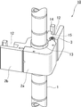
図1は、本願発明による棚用取付け部材10が円筒支柱1に固定された状態を示した図である。棚用取付け部材10はスリーブ13を介して、第1の部分(2a)と第2の部分(2b)が支柱1を挟むようにして嵌合する。つまり、第1の部分(2a)及び第2の部分(2b)の合わせ面は支柱の形状に適合するように加工されており、本実施の形態のような円筒支柱1であれば、第1の部分(2a)と第2の部分(2b)が嵌合したとき、合わせ面の孔の垂直断面が円形を形成するように加工されている。棚用取付け部材10の材質は、金属製であっても、樹脂製であってもよい。
FIG. 1 is a view showing a state in which a
第1の部分(2a)と第2の部分(2b)のそれぞれを製造した後、回動部3を介して第1の部分(2a)及び第2の部分(2b)が連結される。回動部3の形状は、第1の部分(2a)の片側端部が略円柱となるように加工され、この円柱形状にあわせて第2の部分(2b)の一部が凹形にくり抜かれるように加工する。その結果、第1の部分(2a)の円柱形状の回動部3が回動軸となって回動可能な動きを生じさせる。
なお、回動部3の上下にはネジ穴15があり(図1では、上ネジのみを描画)、ワッシャーを介してボルト14で締結することで第1の部分(2a)と第2の部分(2b)が分離しないようになっている。
After manufacturing each of the first part (2a) and the second part (2b), the first part (2a) and the second part (2b) are connected via the
Note that there are
回動部3の回転軸を中心として、第1の部分(2a)又は第2の部分(2b)の少なくとも一方を回転させると、図2に示すように第1の部分(2a)と第2の部分(2b)の嵌合が外れる。嵌合が外れることで、第1の部分(2a)と第2の部分(2b)により形成されていた支柱1を通すための貫通孔が分割され、外側に広がるため、棚用取付け部材10を上下に動かすことなく横から支柱1から取り外すことができる。
When at least one of the first part (2a) or the second part (2b) is rotated around the rotation axis of the
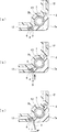
図2に示すように、第1の部分(2a)と第2の部分(2b)が嵌合するのは、回動部3とは反対側の第1の部分(2a)の端部が第2の部分(2b)とラッチ結合する構造になっているからである。ラッチ結合とは、図3の通り、第2の部分(2b)側にバネの付勢力で接合面から常に突き出すように付けられているラッチボルト4が、第1の部分(2a)の端部に設けられた凹状窪み5の端に当接するときバネ6に反対方向の力がかかってラッチボルト4が押し戻され、第1の部分(2a)の凹状窪み5にラッチボルト4が滑り込んで第1の部分(2a)と第2の部分(2b)が固定されることをいう。ラッチ結合後の状態が、上述した図1及び図3(a)である。
As shown in FIG. 2, the first portion (2a) and the second portion (2b) are fitted to each other because the end of the first portion (2a) opposite to the rotating
本発明の棚用取付け部材10を用いて棚受部材7を設置して棚を完成した後、既存の棚受部材のうちの一部の棚受部材を取り外したいときは、その取り外したい一部の棚受部材に関係する棚用取付け部材のみのラッチ結合を解放して支柱1から取り外せばよく、取り外したい一部の棚受部材よりも上方に設置されている他の棚受部材を支柱から取り外すことは何ら必要としないで行えるのである。棚受部材を追加する場合も同様であり、追加する棚受部材よりも上方にある棚受部材を取り外さなくても設置が可能である。
After installing the
ラッチ結合を解放するやり方は、図3に示すように、第1の部分(2a)に設けた凹状隙間8に、ラッチ解放するための工具9を差し込んで(図3(b)参照)、矢印方向(図3(c)参照)に力をかければよい。差し込んだ工具9の先端付近が作用点となり、「てこの原理」による力で第2の部分(2b)のラッチボルト4を第1の部分(2a)の凹状窪み5から容易に外すことができる。
As shown in FIG. 3, a tool 9 for releasing the latch is inserted into the
ラッチ結合を解放する他のやり方を図7に示す。ラッチボルト4に接合した(又はラッチボルトと一体で)ツマミ部11が、第2の部分(2b)の外面から突出している。このツマミ部11を図7(b)の矢印方向に移動させると、ラッチボルト4を第1の部分(2a)側に付勢させているバネ6の力が押し戻されることになるので、ラッチボルト4を第1の部分(2a)の凹状窪み5から外すことができる。
Another way of releasing the latch coupling is shown in FIG. A
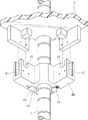
図4は、本発明の棚用取付け部材10に金網状の棚受部材7を載置した後の状態を下方から見たときの図である。棚用取付け部材10の第2の部分(2b)には棚受部材7を取付けるための切り欠き部12があるため、凹凸形状をしている。棚受部材7の金網の棒が切り欠き部12と係合することによって、棚受部材7は棚用取付け部材10に確実に固定される。
FIG. 4 is a view when the state after placing the wire mesh-like
図5は、本発明の棚用取付け部材10に板状の棚受部材7を載置する前の状態を下方から見たときの図であり、図6は、載置した後の状態を下方から見たときの図である。
棚受部材7の下部にある板材が切り欠き部12と係合することによって、棚受部材7は棚用取付け部材10に確実に固定される。しかも、棚用取付け部材10にこの切り欠き部12があるおかげで、支柱間にフレーム部材がなくとも(つまり、棚受部材7以外の棚の構成要素が支柱1のみ)、棚受部材7を支柱1に取付けることが可能である。このため、支柱間のフレーム部材を省けることから、棚全体の低コストを図ることができる。
FIG. 5 is a view when the state before placing the plate-like
The
なお、棚用取付け部材10は支柱1に固定されるようにするため、支柱1にはテーパー状のスリーブ13を設けている。棚用取付け部材10の第1の部分(2a)と第2の部分(2b)はスリーブ13を介して支柱1を挟むことになるため、棚用取付け部材10に棚受部材7を載置して荷重がかかると、支柱1に対する棚用取付け部材10の締め付け力が増すことになる。その結果、棚用取付け部材10の取付けの安定性を確実なものにすることができる。
In order to fix the
なお、本実施の形態では、支柱1が円筒形状であるので、棚用取付け部材10の支柱1を挟むための貫通孔断面が円形となるように第1の部分(2a)及び第2の部分(2b)を加工形成した。しかしながら、支柱1は必ずしも円筒形状であることに限定されるものではなく、矩形など他の形であってもよい。例えば、矩形の支柱の場合は、支柱をしっかり挟むことができるようにするため、第1の部分(2a)及び第2の部分(2b)の嵌合により形成される貫通孔の断面が矩形になるように加工することが必要であることは言うまでもない。
In addition, in this Embodiment, since the support |
1 支柱
2a 第1の部分
2b 第2の部分
3 回動部
4 ラッチボルト
5 凹状窪み
6 バネ
7 棚受部材
8 凹状隙間
9 工具
10 棚用取付け部材
11 ツマミ部
12 切り欠き部
13 スリーブ
14 ボルト
15 ネジ穴
20 棚受部材
21 支柱
23 孔
DESCRIPTION OF
Claims (3)
組立式棚の支柱を挟むように分割して構成された第1の部分と第2の部分が嵌合状態になると前記支柱を貫通させるための貫通孔を形成し、
前記第1の部分の片側端部は前記第2の部分と回動可能にするための回動軸が形成され、前記回動軸は前記第2の部分の嵌合孔とネジ部材で結合し、
前記回動軸まわりに前記第1の部分と前記第2の部分の少なくとも一方が回動すると、前記貫通孔内にある前記支柱から取り外すことが可能であり、
前記第1の部分の他の片側端部は、前記第2の部分とラッチ結合するための凹状窪みを形成し、前記凹状窪みに係合する前記第2の部分のラッチボルトが前記凹状窪みの端に当接するときバネの力で付勢されていた前記ラッチボルトが押し戻されることにより、前記凹状窪みに前記ラッチボルトが滑り込んで前記第1の部分と前記第2の部分が嵌合状態になる、
ように構成されていることを特徴とする棚用取付け部材。 A shelf mounting member for fixing a shelf receiving member of a prefabricated shelf,
When the first part and the second part, which are divided so as to sandwich the column of the assembly-type shelf, are in a fitted state, a through-hole for penetrating the column is formed,
One end of the first portion is formed with a rotation shaft for enabling rotation with the second portion, and the rotation shaft is coupled to the fitting hole of the second portion with a screw member. ,
When at least one of the first part and the second part rotates around the rotation axis, it can be removed from the support column in the through hole,
The other one end of the first portion forms a concave recess for latching engagement with the second portion, and the latch bolt of the second portion that engages with the concave recess is in the concave recess. When the latch bolt, which has been urged by the force of the spring when abutting against the end, is pushed back, the latch bolt slides into the concave recess, and the first portion and the second portion are in a fitted state. ,
It is comprised so that the mounting member for shelves characterized by the above-mentioned.
Priority Applications (1)
| Application Number | Priority Date | Filing Date | Title |
|---|---|---|---|
| JP2014121083A JP6446720B2 (en) | 2014-06-12 | 2014-06-12 | Shelf mounting member |
Applications Claiming Priority (1)
| Application Number | Priority Date | Filing Date | Title |
|---|---|---|---|
| JP2014121083A JP6446720B2 (en) | 2014-06-12 | 2014-06-12 | Shelf mounting member |
Publications (3)
| Publication Number | Publication Date |
|---|---|
| JP2016000112A true JP2016000112A (en) | 2016-01-07 |
| JP2016000112A5 JP2016000112A5 (en) | 2017-06-15 |
| JP6446720B2 JP6446720B2 (en) | 2019-01-09 |
Family
ID=55076071
Family Applications (1)
| Application Number | Title | Priority Date | Filing Date |
|---|---|---|---|
| JP2014121083A Expired - Fee Related JP6446720B2 (en) | 2014-06-12 | 2014-06-12 | Shelf mounting member |
Country Status (1)
| Country | Link |
|---|---|
| JP (1) | JP6446720B2 (en) |
Cited By (1)
| Publication number | Priority date | Publication date | Assignee | Title |
|---|---|---|---|---|
| WO2020105185A1 (en) * | 2018-11-22 | 2020-05-28 | 株式会社ナカムラ | Attachment structure for member |
Citations (7)
| Publication number | Priority date | Publication date | Assignee | Title |
|---|---|---|---|---|
| JPH05199920A (en) * | 1992-01-24 | 1993-08-10 | Daifuku Co Ltd | Shelf attaching device |
| JPH0826119A (en) * | 1994-07-19 | 1996-01-30 | Itochu Pura Kemitsuku Kk | Cart for tray |
| JP3069092U (en) * | 1999-11-19 | 2000-05-30 | 楊 信誠 | Easy to assemble and disassemble |
| JP2000308528A (en) * | 1999-04-28 | 2000-11-07 | Iris Ohyama Inc | Rack member, intermediate member for fixing rack and assembled rack |
| US6364139B1 (en) * | 2000-10-31 | 2002-04-02 | Pro Trend Co., Ltd. | Two-part shelf-holder for sectional rack |
| JP2002142879A (en) * | 2000-10-25 | 2002-05-21 | Eita Kigyo Yugenkoshi | Shelf positioning device for pipe rack |
| JP2010057558A (en) * | 2008-09-01 | 2010-03-18 | Lec Inc | Hanging device |
-
2014
- 2014-06-12 JP JP2014121083A patent/JP6446720B2/en not_active Expired - Fee Related
Patent Citations (7)
| Publication number | Priority date | Publication date | Assignee | Title |
|---|---|---|---|---|
| JPH05199920A (en) * | 1992-01-24 | 1993-08-10 | Daifuku Co Ltd | Shelf attaching device |
| JPH0826119A (en) * | 1994-07-19 | 1996-01-30 | Itochu Pura Kemitsuku Kk | Cart for tray |
| JP2000308528A (en) * | 1999-04-28 | 2000-11-07 | Iris Ohyama Inc | Rack member, intermediate member for fixing rack and assembled rack |
| JP3069092U (en) * | 1999-11-19 | 2000-05-30 | 楊 信誠 | Easy to assemble and disassemble |
| JP2002142879A (en) * | 2000-10-25 | 2002-05-21 | Eita Kigyo Yugenkoshi | Shelf positioning device for pipe rack |
| US6364139B1 (en) * | 2000-10-31 | 2002-04-02 | Pro Trend Co., Ltd. | Two-part shelf-holder for sectional rack |
| JP2010057558A (en) * | 2008-09-01 | 2010-03-18 | Lec Inc | Hanging device |
Cited By (3)
| Publication number | Priority date | Publication date | Assignee | Title |
|---|---|---|---|---|
| WO2020105185A1 (en) * | 2018-11-22 | 2020-05-28 | 株式会社ナカムラ | Attachment structure for member |
| JPWO2020105185A1 (en) * | 2018-11-22 | 2021-10-07 | 株式会社ナカムラ | Member mounting structure |
| JP7011351B2 (en) | 2018-11-22 | 2022-01-26 | 株式会社ナカムラ | Member mounting structure |
Also Published As
| Publication number | Publication date |
|---|---|
| JP6446720B2 (en) | 2019-01-09 |
Similar Documents
| Publication | Publication Date | Title |
|---|---|---|
| US20180084908A1 (en) | Bracket device | |
| KR101953422B1 (en) | Self-indexing nut plate | |
| US20160165741A1 (en) | Fixing member of rack server | |
| US20150181726A1 (en) | Mounting apparatus and screw assembly for the same | |
| WO2016037348A1 (en) | Installation support and box | |
| JP6446720B2 (en) | Shelf mounting member | |
| US9156413B2 (en) | Fixing mount of bicycle carrier | |
| JP3737507B1 (en) | Assembly structure | |
| TW201424518A (en) | Mounting apparatus for circuit board | |
| KR200472074Y1 (en) | Prefabricated construct | |
| KR101719055B1 (en) | Fixing and taking away device of cover for light | |
| KR20080004381U (en) | Multi-assembly jig | |
| KR20170072453A (en) | Shield mountable structure of chamber | |
| JP6406874B2 (en) | Screw fastening structure of plate material | |
| JP5605818B1 (en) | Prop mounting structure | |
| TWM482240U (en) | Mounting device | |
| JP2017100263A (en) | Decomposition tool | |
| JP6786564B2 (en) | Fixing device and method for mounting the sensor in the opening | |
| JP7201224B2 (en) | Interlocking structure of prefabricated shelves | |
| JP4821729B2 (en) | Storage furniture fixing structure | |
| CN204141162U (en) | Fixed mechanism and use the The Cloud Terrace of this fixed mechanism | |
| CN209883509U (en) | Wardrobe door handle | |
| KR200447863Y1 (en) | Mounting structure of fixing equipment | |
| JP6077977B2 (en) | Shelf board mounting structure | |
| KR200385538Y1 (en) | Side support construct structure of PDP/LCD module base |
Legal Events
| Date | Code | Title | Description |
|---|---|---|---|
| A521 | Request for written amendment filed |
Free format text: JAPANESE INTERMEDIATE CODE: A523 Effective date: 20170428 |
|
| A621 | Written request for application examination |
Free format text: JAPANESE INTERMEDIATE CODE: A621 Effective date: 20170428 |
|
| A977 | Report on retrieval |
Free format text: JAPANESE INTERMEDIATE CODE: A971007 Effective date: 20180215 |
|
| A131 | Notification of reasons for refusal |
Free format text: JAPANESE INTERMEDIATE CODE: A131 Effective date: 20180322 |
|
| A521 | Request for written amendment filed |
Free format text: JAPANESE INTERMEDIATE CODE: A523 Effective date: 20180521 |
|
| TRDD | Decision of grant or rejection written | ||
| A01 | Written decision to grant a patent or to grant a registration (utility model) |
Free format text: JAPANESE INTERMEDIATE CODE: A01 Effective date: 20181107 |
|
| A61 | First payment of annual fees (during grant procedure) |
Free format text: JAPANESE INTERMEDIATE CODE: A61 Effective date: 20181113 |
|
| R150 | Certificate of patent or registration of utility model |
Ref document number: 6446720 Country of ref document: JP Free format text: JAPANESE INTERMEDIATE CODE: R150 |
|
| LAPS | Cancellation because of no payment of annual fees |