JP2015536447A - Rod-type thermometer device for temperature detection, usage method for electric simulation of nuclear fuel rod - Google Patents
Rod-type thermometer device for temperature detection, usage method for electric simulation of nuclear fuel rod Download PDFInfo
- Publication number
- JP2015536447A JP2015536447A JP2015537399A JP2015537399A JP2015536447A JP 2015536447 A JP2015536447 A JP 2015536447A JP 2015537399 A JP2015537399 A JP 2015537399A JP 2015537399 A JP2015537399 A JP 2015537399A JP 2015536447 A JP2015536447 A JP 2015536447A
- Authority
- JP
- Japan
- Prior art keywords
- rod
- metal
- covering
- tube
- wire
- Prior art date
- Legal status (The legal status is an assumption and is not a legal conclusion. Google has not performed a legal analysis and makes no representation as to the accuracy of the status listed.)
- Pending
Links
Images


Classifications
-
- G—PHYSICS
- G01—MEASURING; TESTING
- G01K—MEASURING TEMPERATURE; MEASURING QUANTITY OF HEAT; THERMALLY-SENSITIVE ELEMENTS NOT OTHERWISE PROVIDED FOR
- G01K1/00—Details of thermometers not specially adapted for particular types of thermometer
- G01K1/02—Means for indicating or recording specially adapted for thermometers
- G01K1/026—Means for indicating or recording specially adapted for thermometers arrangements for monitoring a plurality of temperatures, e.g. by multiplexing
-
- B—PERFORMING OPERATIONS; TRANSPORTING
- B23—MACHINE TOOLS; METAL-WORKING NOT OTHERWISE PROVIDED FOR
- B23K—SOLDERING OR UNSOLDERING; WELDING; CLADDING OR PLATING BY SOLDERING OR WELDING; CUTTING BY APPLYING HEAT LOCALLY, e.g. FLAME CUTTING; WORKING BY LASER BEAM
- B23K9/00—Arc welding or cutting
- B23K9/0026—Arc welding or cutting specially adapted for particular articles or work
- B23K9/0035—Arc welding or cutting specially adapted for particular articles or work of thin articles
-
- B—PERFORMING OPERATIONS; TRANSPORTING
- B23—MACHINE TOOLS; METAL-WORKING NOT OTHERWISE PROVIDED FOR
- B23K—SOLDERING OR UNSOLDERING; WELDING; CLADDING OR PLATING BY SOLDERING OR WELDING; CUTTING BY APPLYING HEAT LOCALLY, e.g. FLAME CUTTING; WORKING BY LASER BEAM
- B23K9/00—Arc welding or cutting
- B23K9/007—Spot arc welding
-
- G—PHYSICS
- G01—MEASURING; TESTING
- G01K—MEASURING TEMPERATURE; MEASURING QUANTITY OF HEAT; THERMALLY-SENSITIVE ELEMENTS NOT OTHERWISE PROVIDED FOR
- G01K7/00—Measuring temperature based on the use of electric or magnetic elements directly sensitive to heat ; Power supply therefor, e.g. using thermoelectric elements
- G01K7/02—Measuring temperature based on the use of electric or magnetic elements directly sensitive to heat ; Power supply therefor, e.g. using thermoelectric elements using thermoelectric elements, e.g. thermocouples
- G01K7/04—Measuring temperature based on the use of electric or magnetic elements directly sensitive to heat ; Power supply therefor, e.g. using thermoelectric elements using thermoelectric elements, e.g. thermocouples the object to be measured not forming one of the thermoelectric materials
- G01K7/06—Measuring temperature based on the use of electric or magnetic elements directly sensitive to heat ; Power supply therefor, e.g. using thermoelectric elements using thermoelectric elements, e.g. thermocouples the object to be measured not forming one of the thermoelectric materials the thermoelectric materials being arranged one within the other with the junction at one end exposed to the object, e.g. sheathed type
-
- G—PHYSICS
- G21—NUCLEAR PHYSICS; NUCLEAR ENGINEERING
- G21C—NUCLEAR REACTORS
- G21C17/00—Monitoring; Testing ; Maintaining
- G21C17/10—Structural combination of fuel element, control rod, reactor core, or moderator structure with sensitive instruments, e.g. for measuring radioactivity, strain
- G21C17/112—Measuring temperature
-
- Y—GENERAL TAGGING OF NEW TECHNOLOGICAL DEVELOPMENTS; GENERAL TAGGING OF CROSS-SECTIONAL TECHNOLOGIES SPANNING OVER SEVERAL SECTIONS OF THE IPC; TECHNICAL SUBJECTS COVERED BY FORMER USPC CROSS-REFERENCE ART COLLECTIONS [XRACs] AND DIGESTS
- Y02—TECHNOLOGIES OR APPLICATIONS FOR MITIGATION OR ADAPTATION AGAINST CLIMATE CHANGE
- Y02E—REDUCTION OF GREENHOUSE GAS [GHG] EMISSIONS, RELATED TO ENERGY GENERATION, TRANSMISSION OR DISTRIBUTION
- Y02E30/00—Energy generation of nuclear origin
- Y02E30/30—Nuclear fission reactors
-
- Y—GENERAL TAGGING OF NEW TECHNOLOGICAL DEVELOPMENTS; GENERAL TAGGING OF CROSS-SECTIONAL TECHNOLOGIES SPANNING OVER SEVERAL SECTIONS OF THE IPC; TECHNICAL SUBJECTS COVERED BY FORMER USPC CROSS-REFERENCE ART COLLECTIONS [XRACs] AND DIGESTS
- Y10—TECHNICAL SUBJECTS COVERED BY FORMER USPC
- Y10T—TECHNICAL SUBJECTS COVERED BY FORMER US CLASSIFICATION
- Y10T29/00—Metal working
- Y10T29/49—Method of mechanical manufacture
- Y10T29/49002—Electrical device making
- Y10T29/49117—Conductor or circuit manufacturing
- Y10T29/49119—Brush
Abstract
【課題】より高い空間測定密度での温度検出、機器コストの低減および再利用等の必要性を少なくとも部分的に満たす新しい温度検出装置の提供。【解決手段】本発明は、複数の温度検知要素および該検知要素が部分的に挿入されている軸Xを有する保護用被覆部を備えた、温度を検出するためのロッド状温度計に関する。被覆部は、熱電対の2つの金属の1つを構成する金属で作られ、且つ該検知要素は、該被覆部の該金属とは異なる金属で作られた複数のワイヤから成り、且つ熱電対の該2つの金属の他方を構成し、該ワイヤの各々の端部の1つは、所与の熱電対の測定接合部を形成するように該被覆部の内側部へ溶接され、該ワイヤの該溶接された端部は、該被覆部の該内側部の該軸Xに対して軸方向かつ方位角方向の複数の位置に分布され、該ワイヤの各々はその端部の少なくとも1つによって該被覆部の外へ延在する。本発明は、核燃料棒の電気的シミュレーションについて有用である。【選択図】図3The present invention provides a new temperature detection device that at least partially satisfies the need for temperature detection at a higher spatial measurement density, reduction in equipment costs, and reuse. The present invention relates to a rod-shaped thermometer for detecting temperature, comprising a protective covering having a plurality of temperature sensing elements and an axis X into which the sensing elements are partially inserted. The sheath is made of a metal that constitutes one of the two metals of the thermocouple, and the sensing element comprises a plurality of wires made of a metal different from the metal of the sheath, and the thermocouple One of each end of the wire is welded to the inside of the sheath to form a measurement junction for a given thermocouple, The welded ends are distributed at a plurality of axial and azimuthal positions relative to the axis X of the inner portion of the sheath, each of the wires being at least one of its ends by the at least one of the ends. It extends out of the covering. The present invention is useful for electrical simulation of nuclear fuel rods. [Selection] Figure 3
Description
本発明は、多点で温度を検出するよう設計された多点ロッド状温度計を形成する新型の温度検出装置に関する。 The present invention relates to a new type of temperature detection device that forms a multi-point rod thermometer designed to detect temperature at multiple points.
本発明の主要な応用は、核燃料棒を電気的にシミュレートする装置により、沸騰の危機の発生を検出することであり、該核燃料棒は、スペーサー格子を用いてアセンブリに組み立てられることが意図され、且つ動力炉およびより特別には加圧水型原子炉(PWRs)と呼ばれるものに用いられことが意図される。 A major application of the present invention is to detect the occurrence of a boiling crisis by means of an apparatus that electrically simulates a nuclear fuel rod, which is intended to be assembled into an assembly using a spacer grid. And intended for use in power reactors and more particularly what are called pressurized water reactors (PWRs).
そのような装置の実装は、核燃料棒を熱水力的に品質評価することを可能にし、そして特に、燃料棒が浸けられることを意図された液体において、沸騰の危機の発生を、実際の原子炉の代表である条件の下で検出することを可能にする。沸騰の危機の発生および場所は、電気的シミュレーション装置内で、安全システムを起動することを可能にする応答時間で検出されねばならない。 The implementation of such a device makes it possible to hydrodynamically evaluate the nuclear fuel rods, and in particular in the liquid intended for the fuel rods to be immersed, the occurrence of a boiling crisis, Allows detection under conditions that are representative of the furnace. The occurrence and location of the boiling crisis must be detected within the electrical simulation device with a response time that allows the safety system to be activated.
一般に、本発明は、軸方向かつ方位角方向の複数の位置に分布され且つ特に高い空間密度で分布されている様々な点での温度を、1つの且つ同じ装置を用いて検出することを目的とする。 In general, the present invention aims to detect temperatures at various points distributed at a plurality of axial and azimuthal positions and distributed at a particularly high spatial density using one and the same device. And
主要な応用に関して記載されているが、本発明に従う温度検出装置は、監視されるべき所与の壁の様々な点での様々な温度又は温度勾配を検出するために用いられ、各点での温度は輻射熱によって検出される。 Although described with respect to the main application, the temperature sensing device according to the present invention is used to detect different temperatures or temperature gradients at different points of a given wall to be monitored, and at each point. The temperature is detected by radiant heat.
加圧水型原子炉(PWRs)に用いられことが意図された核燃料棒アセンブリを品質評価するために、沸騰危機試験を実施することが必要である。より詳細には、沸騰危機の発生と場所を検出することが必要である。具体的には、沸騰危機は、一般的に、熱水力的制御パラメータの小変化に対する壁の温度の実質的な変化として定義されうる。沸騰危機は、加熱された壁とそれを囲む冷却材との間の熱交換における急激な悪化によって現れる。したがって、加圧水型原子炉(PWR)において、この結果の発生は、核燃料棒のひび割れを引き起こし破壊する。 In order to assess the quality of nuclear fuel rod assemblies intended to be used in pressurized water reactors (PWRs), it is necessary to conduct a boiling crisis test. More specifically, it is necessary to detect the occurrence and location of the boiling crisis. Specifically, a boiling crisis can generally be defined as a substantial change in wall temperature for a small change in thermohydraulic control parameters. The boiling crisis is manifested by a sudden deterioration in heat exchange between the heated wall and the surrounding coolant. Thus, in a pressurized water reactor (PWR), this resulting occurrence causes cracking of the nuclear fuel rod and destroys it.
言い換えると、核燃料棒アセンブリ(これは限定されるべき該燃料の第1の封じ込め障壁である)は、計画通りの動作、事故又は過渡的制御、および棒のひび割れ損傷のリスク中に遭遇する動作条件に対して、動作許容範囲の診断を可能にするために、沸騰危機に対して品質評価されなければならない。 In other words, the nuclear fuel rod assembly (which is the first containment barrier of the fuel to be limited) is the operating condition encountered during planned operation, accident or transient control, and risk of rod cracking damage. On the other hand, quality must be evaluated against the boiling crisis in order to allow diagnosis of operational tolerances.
この品質評価は、沸騰危機の発生及び場所を、高熱流束密度を発生する核燃料棒を電気的にシミュレーションする装置によって実験的に規定することから成る。シミュレーション装置の実装は、該装置をほとんど妨害されない液体の流れの中に沈めること、および、他のパラメータを所定の一定値に調節しながら、沸騰危機が得られるまで単一の熱水力的パラメータをゆっくりと変化させることから成る。 This quality assessment consists of experimentally defining the occurrence and location of the boiling crisis by means of an apparatus that electrically simulates nuclear fuel rods that generate high heat flux densities. The implementation of the simulation device involves submerging the device in a liquid flow that is largely undisturbed, and adjusting the other parameters to a predetermined constant value, while maintaining a single thermo-hydraulic parameter until a boiling crisis is obtained. It consists of slowly changing.
高熱流束密度を発生する核燃料棒を電気的にシミュレーションするのに用いられる装置に関しては、使用されたこれらのほとんどが、直接加熱装置として言及されたものである、なぜなら、装置のひび割れ、これは熱湯と接触させるものであり、同様に抵抗加熱要素を構成するからである。 With respect to the equipment used to electrically simulate nuclear fuel rods that generate high heat flux densities, most of these used are referred to as direct heating equipment because of equipment cracking, which is This is because it is brought into contact with hot water and similarly constitutes a resistance heating element.
本出願人はまた、仏国特許出願公開第 11 54336号公報(2011年5月18日出願)において、間接加熱を採用する電気的シミュレーション装置を提案している。該装置は、特に電気的伝導性の冷却材内に沈められることが意図された核燃料アセンブリ、例えば、冷却材としてナトリウムを用いた(Na-FBRs)第IV世代高速増殖炉(FBRs)の場合で、該炉は高熱流束密度ナトリウム沸騰試験が実行される必要がある、を品質評価することを可能にする。 The present applicant has also proposed an electrical simulation apparatus that employs indirect heating in French Patent Application No. 11 54336 (filed on May 18, 2011). The device is particularly intended for nuclear fuel assemblies intended to be submerged in electrically conductive coolant, for example in the case of fourth generation fast breeder reactors (FBRs) using sodium as the coolant (Na-FBRs) The furnace makes it possible to evaluate the quality of the high heat flux density sodium boiling test that needs to be performed.
電気的シミュレーション装置のタイプがどのようなものであろうと、沸騰危機の発生とその場所の検出は、高い空間測定密度、および安全性の理由のために、非常に短い応答時間、非常に厳しいアクセス制限を必要とする。なぜなら該装置は小径の管で作られているからである。特に、一般に中性子による均一でない軸方向プロファイルを有する高い熱流束密度によって、高い空間測定密度が要求される。格子は、原子炉内のアセンブリの格子と同じ形状、寸法および軸方向位置である。 Whatever the type of electrical simulation equipment, the occurrence of boiling crisis and detection of its location is due to high spatial measurement density, and safety reasons, very short response time, very tight access Requires restrictions. This is because the device is made of small diameter tubes. In particular, a high spatial measurement density is required due to the high heat flux density, which generally has a non-uniform axial profile due to neutrons. The grid is the same shape, dimensions and axial position as the grid of the assembly in the reactor.
これまでのところ実際には、直接加熱を採用するシミュレーション装置において、鋼または別の類似の物質で被覆された熱電対は、監視されるべき点、即ち沸騰危機が予想される領域内で、加熱される被覆部へ直接に溶接される。この技術は、以下のように列挙されうる多くの欠点を有する:
‐ それは、該装置内で熱電対のために利用可能な、非常に制限された空間のせいで、測定点の数を実質的に限定する;
‐ それは、被覆部内の加熱用電流、したがって熱流束密度ひいては観測される沸騰危機の局所的な崩壊を引き起こしうる;
‐ それは、投資の観点および測定点を形成するのに必要な人‐時間の観点から、より特別には多数の試験の場合に、相対的に高価である;さらに、
‐ この技術で、測定器具および加熱された被覆部を再生することは不可能である。
So far, in practice, in simulation equipment employing direct heating, thermocouples coated with steel or another similar material are heated to the point where they are to be monitored, i.e. in the region where a boiling crisis is expected. Directly welded to the coating. This technique has a number of drawbacks that can be enumerated as follows:
It substantially limits the number of measurement points due to the very limited space available for thermocouples in the device;
-It can cause heating currents in the cladding, and thus the heat flux density and thus the local collapse of the observed boiling crisis;
It is relatively expensive in terms of investment and the person-time required to form the measurement point, more particularly in the case of a large number of tests;
-With this technique it is impossible to regenerate the measuring instrument and the heated coating.
前述された仏国特許出願公開第 11 54336号公報の間接加熱を採用する該シミュレーション装置において、出願人は、複数の熱電対の各々を、加熱されるべき液体と直接接触させるために、加熱されない被覆部の外側周辺部上に作られた溝に挿入することを提案しており、熱電対を高精度で配置することを可能にするという付随する有利点を伴う。それにもかかわらず、測定点の数は制限されたままであり、測定点の形成のコストは高いままであり、そして測定機器および機器を搭載した被覆部を再生することは、この技術でもやはり可能ではない。 In the simulation apparatus employing the indirect heating of the above-mentioned French Patent Application No. 11 54336, the applicant is not heated in order to bring each of the plurality of thermocouples into direct contact with the liquid to be heated. It has been proposed to be inserted into a groove made on the outer periphery of the covering, with the attendant advantages of allowing the thermocouple to be placed with high precision. Nevertheless, the number of measurement points remains limited, the cost of forming the measurement points remains high, and it is still possible with this technology to regenerate the measuring instrument and the covering with the instrument. Absent.
さらに、温度検出装置、一般に多点ロッド状温度計/高温計と呼ばれる、は、保護用被覆部内に収容された温度を検知しうる要素、例えば抵抗温度計、熱電効果対すなわちサーミスタを備え、公知である。これらロッド状温度計は、温度が検出される対象物の1つ以上の壁に物理的に影響を与えることなく且つ温度測定の後に再生可能に「その場で」埋め込まれうるという有利点を有する。これは、現在利用可能なロッド状温度計が、非常に高い空間測定密度を得ることを可能にしないということであり、相対的に高価であり、そして実際に、利用可能な空間、即ち換言するとアクセスが非常に限定されるところの領域に埋め込むことができない。 Furthermore, a temperature detection device, commonly called a multi-point rod thermometer / pyrometer, is equipped with elements capable of detecting the temperature accommodated in the protective covering, such as a resistance thermometer, a thermoelectric effect pair or thermistor, etc. It is. These rod-type thermometers have the advantage that they can be embedded “in situ” without physically affecting one or more walls of the object whose temperature is to be detected and reproducibly after the temperature measurement. . This means that currently available rod thermometers do not make it possible to obtain very high spatial measurement densities, are relatively expensive, and in fact, available space, i.e. It cannot be embedded in areas where access is very limited.
したがって、既存の温度検出装置および技術を、特に、利用可能なアクセス空間が非常に限定されている領域においてさえ、より高い空間測定密度を得る観点で、監視されるべき壁を測定するための機器のコストを低減する観点で、並びに、測定機器および監視された壁、例えば核燃料棒を電気的にシミュレーションする装置の加熱された若しくは加熱されなかった被覆部を再生しかつ再利用することを可能にする観点で改良する必要がある。 Thus, existing temperature sensing devices and techniques, particularly in areas where the available access space is very limited, are instruments for measuring the walls to be monitored in terms of obtaining a higher spatial measurement density Enabling to regenerate and reuse the heated or unheated cladding of the device that electrically simulates the measuring equipment and monitored walls, eg nuclear fuel rods, as well as reducing the cost of It is necessary to improve in view of
したがって、本発明の一般的な目的は、これらの必要性を少なくとも部分的に満たす新しい温度検出装置を提供することである。 Accordingly, it is a general object of the present invention to provide a new temperature sensing device that at least partially meets these needs.
本発明の1つの特別な目的は、核燃料棒を電気的にシミュレーションするための装置において用いられうる温度検出装置を提供することである。 One particular object of the present invention is to provide a temperature sensing device that can be used in an apparatus for electrically simulating nuclear fuel rods.
これを行うため、その局面の1つに従う本発明の課題は、温度を検出するための装置であって、ロッド状温度計を形成し、
- 温度を検知しうる複数の要素、
- 該検知しうる要素が部分的に収納されている長手方向軸Xを持つ保護用被覆部、
を備え、
該被覆部は、熱電対の2つの金属の1つを構成する金属で作られていること、および該検知しうる要素は、該被覆部の該金属とは異なる金属で作られ且つ熱電対の該2つの金属の他方を構成する複数のワイヤから成り、該ワイヤの各々の端部の1つは、所与の熱電対の測定接合部を形成するように該被覆部の内側部へ溶接され、該ワイヤの該溶接された端部は、該被覆部の該内側部で該軸Xに対して軸方向かつ方位角方向の複数の位置に分布され、該ワイヤの各々は、該被覆部からその端部の少なくとも1つを介して出ること、を特徴とする。
In order to do this, the subject of the invention according to one of its aspects is a device for detecting temperature, which forms a rod-shaped thermometer,
-Multiple elements that can detect temperature,
A protective covering with a longitudinal axis X in which the detectable element is partially housed,
With
The covering is made of a metal that constitutes one of the two metals of the thermocouple, and the detectable element is made of a metal different from the metal of the covering and of the thermocouple It consists of a plurality of wires that make up the other of the two metals, one end of each of the wires being welded to the inner part of the sheath to form a measurement junction for a given thermocouple. The welded ends of the wire are distributed at a plurality of axial and azimuthal positions relative to the axis X at the inner portion of the sheath, each of the wires extending from the sheath Exiting through at least one of its ends.
言い換えれば、本発明は、ロッド状温度計の被覆部を与えることから成る。該被覆部は、従来技術においてはただ検知要素を保護する機能を有したのみであるが、別の機能、すなわち複数の熱電対に共通の金属の機能、該被覆部へ直接に溶接されたワイヤの金属である熱電対の各々のもう一方の金属、軸方向かつ方位角方向の複数の位置に分布された該ワイヤを有する。 In other words, the present invention consists in providing a covering for a rod-shaped thermometer. The covering only has the function of protecting the sensing element in the prior art, but another function, that is, the function of a metal common to a plurality of thermocouples, the wire welded directly to the covering The other metal of each thermocouple, the wire being distributed at a plurality of axial and azimuthal positions.
更に換言すれば、本発明に従うと、該被覆部の該金属は、熱電対の2つの金属の1つとして、および全ての熱電対に共通の金属として用いられ、壁温度は、該熱電対のもう一方の金属で作られた単一のワイヤで設定された1点で放射熱によって検出される。 In other words, according to the present invention, the metal of the covering is used as one of the two metals of the thermocouple and as a metal common to all thermocouples, and the wall temperature is the temperature of the thermocouple. It is detected by radiant heat at one point set by a single wire made of the other metal.
本発明のおかげで、測定機器のコストを相対的に低く保ちつつ、監視されるべき対象毎に数百もの領域において温度を検出することが可能であり、そのような対象は場合によっては核燃料棒の電気的シミュレータでありえる。本発明に従うロッド状温度計は、さらに監視されるべき対象から独立しており、従って該ロッド状温度計および監視されるべき複数の対象(そのような対象は場合によっては電気的シミュレーション装置の加熱された被覆部でありうる)は、多数回、再利用されうる。 Thanks to the present invention, it is possible to detect temperatures in the hundreds of regions for each object to be monitored, while keeping the cost of the measuring equipment relatively low, such objects in some cases nuclear fuel rods It can be an electric simulator. The rod-type thermometer according to the invention is further independent of the object to be monitored, and therefore the rod-shaped thermometer and a plurality of objects to be monitored (such objects are sometimes heated by an electrical simulation device). Can be reused many times.
換言すれば、本発明に従うロッド状温度計は、従来技術の検出技術に対して多くの有利点を有する:
‐ それは、温度検出点の数を、典型的には直線的センチメータ(linear centimeter)当たり数個まで増加させる;
‐ 該熱電対は、熱流束密度を局所的に乱さない;
‐ 測定機器のコストは、実質的に低下される;
‐ 該ロッド状温度計および監視されるべき対象(そのような対象は場合によっては加熱された被覆部でありうる)は、容易に回収される;
‐ 本発明に従う該ロッド状温度計は、検出点の非常に高い空間密度の故に、環境条件の広い範囲の下で温度を検出するように適合されうる。
In other words, the rod thermometer according to the present invention has many advantages over the prior art detection techniques:
-It increases the number of temperature detection points, typically to a few per linear centimeter;
-The thermocouple does not locally disturb the heat flux density;
-The cost of measuring equipment is substantially reduced;
The rod-shaped thermometer and the object to be monitored (such an object may possibly be a heated coating) are easily recovered;
The rod thermometer according to the invention can be adapted to detect temperature under a wide range of environmental conditions due to the very high spatial density of the detection points.
好ましくは、該被覆部の該金属は、タイプ‐Kの物質である。 Preferably, the metal of the covering is a type-K material.
同様に好ましくは、該ワイヤの該金属は、タイプ‐Kの物質である。 Also preferably, the metal of the wire is a type-K material.
それにより、1の好ましい別の実施態様に従うと、該被覆部は、クロメルまたはニッケル/クロム合金、例えばInconel(商標)600のどちらかで作られ、且つ該ワイヤはアルメルから作られている。そのようなタイプ‐Kの熱電対は、広い温度範囲を測定でき、且つ高価でないという有利点を有している。 Thus, according to one preferred alternative embodiment, the covering is made of either chromel or a nickel / chromium alloy, such as Inconel ™ 600, and the wire is made of alumel. Such type-K thermocouples have the advantage that they can measure a wide temperature range and are not expensive.
1の有利的な特徴に従うと、該ワイヤは、それらの接合端部は別にして、電気絶縁物で被覆されている。すなわち、各熱電対は他の熱電対および該被覆部から電気的に絶縁されている。1の好ましい別の実施態様に従うと、該アルメルワイヤは、アルミナ沈着物で被覆される。 According to one advantageous feature, the wires are covered with an electrical insulator, apart from their joint ends. That is, each thermocouple is electrically insulated from other thermocouples and the covering portion. According to one preferred alternative embodiment, the alumel wire is coated with an alumina deposit.
好ましくは、該被覆部の厚みは0.1mm以下である。 Preferably, the thickness of the covering portion is 0.1 mm or less.
同様に好ましくは、該ワイヤの外径は0.1mm以下である。これらの寸法で、ワイヤと該被覆部との間の接合部での測定点の熱慣性は、相対的に小さく、それによって相対的に短い応答時間を保証する。すなわち、沸騰危機の発生を非常に速く検出することが可能である。典型的には、直接加熱を採用する電気的シミュレーション装置において、750℃未満の加熱された被覆部温度に対して、該被覆部の1秒当り約1000℃の温度増加に対して、発明者らは、本発明に従うロッド状温度計のおかげで、所要検出閾値、典型的には100msよりも短い時間に10℃を超える温度変動を検出することは可能であると考えている。核燃料棒を電気的にシミュレートするための装置における沸騰危機は、このようにして、温度変動が設定閾値(少なくとも10℃に等しい)を超えるや否や検出される。 Similarly, preferably, the outer diameter of the wire is 0.1 mm or less. With these dimensions, the thermal inertia of the measuring point at the joint between the wire and the sheath is relatively small, thereby ensuring a relatively short response time. That is, it is possible to detect the occurrence of a boiling crisis very quickly. Typically, in an electrical simulation device that employs direct heating, for heated coating temperatures below 750 ° C., for the temperature increase of about 1000 ° C. per second of the coating, we have Believes that thanks to the rod thermometer according to the invention it is possible to detect temperature fluctuations exceeding 10 ° C. in a time shorter than the required detection threshold, typically less than 100 ms. A boiling crisis in an apparatus for electrically simulating nuclear fuel rods is thus detected as soon as the temperature variation exceeds a set threshold (equal to at least 10 ° C.).
1の有利な特徴に従うと、該ロッド状温度計は、該被覆部と同じ金属から作られ且つ該被覆部の外径よりも大きな外径の少なくとも1つのアダプター管(41)を備え、該アダプター管は、該金属ワイヤが出て行く端部で被覆部の回りでろう付けされている。このことは、加熱された被覆部内にロッド状温度計を嵌め込むのを容易にする。 According to one advantageous characteristic, the rod-shaped thermometer comprises at least one adapter tube (41) made of the same metal as the covering and having an outer diameter larger than the outer diameter of the covering. The tube is brazed around the sheath at the end where the metal wire exits. This makes it easy to fit the rod-shaped thermometer in the heated coating.
本発明の別の局面に従う本発明の別の課題は、上述されたロッド状温度計を製造するための方法であり、以下の工程:
‐ 2つの半管を形成するように、熱電対の2つの金属の1つを構成する金属で作られた管を、2つの向かい合う母線に沿って長手方向に切断すること、
‐ 熱電対の2つの金属の1つを構成する金属で作られた複数のワイヤの各々の1の端部を、少なくとも1つの半管の内側部へ溶接し、該溶接されたワイヤの該端部は、軸方向かつ方位角方向の複数の位置に分布させられていること、および
‐ 該金属管を、各母線に沿う溶接によって再構成して該被覆部を形成すること、一方、該複数の金属ワイヤは、該被覆部からその端部の少なくとも1つを介して出たままにしておくこと、
を包含する。
Another subject of the present invention according to another aspect of the present invention is a method for manufacturing the rod-shaped thermometer described above, and the following steps:
-Cutting a tube made of metal that constitutes one of the two metals of the thermocouple longitudinally along two opposing busbars to form two half tubes;
-Welding one end of each of a plurality of wires made of metal that constitutes one of the two metals of the thermocouple to the inner part of at least one half-tube, the end of the welded wire The parts are distributed at a plurality of axial and azimuthal positions, and the metal tube is reconfigured by welding along each busbar to form the covering, Leaving the metal wire out of the sheath through at least one of its ends,
Is included.
そのような製造方法は、該半管の内部はアクセスが容易であるため、特に実装することが簡単である。各金属ワイヤはまた、約百メートルのワイヤを保持している従来のリールから容易に解かれうる。 Such a manufacturing method is particularly easy to implement because the interior of the half tube is easy to access. Each metal wire can also be easily unwound from a conventional reel holding about a hundred meters of wire.
好ましくは、該ワイヤの該端部の1つの、少なくとも1つの半管への該溶接は、アーク溶接によって実現される。 Preferably, the welding of one end of the wire to at least one half tube is accomplished by arc welding.
同様に好ましくは、該再構成溶接はスポット溶接である。これらよく特徴付けられた溶接技術は、非常に正確な測定接合が作られることを可能にする。 Likewise preferably, the reconstruction welding is spot welding. These well-characterized welding techniques allow very accurate measurement joints to be made.
別の局面に従う本発明はまた、核燃料棒を電気的にシミュレートするための装置内に上に記載された該温度検出装置を実装するための方法に関しており、該核燃料棒は、電気伝導性材料で作られた少なくとも1つの管、被加熱管と呼ばれる、を備え、該管は該液体を加熱するように意図され、液体内での沸騰危機の発生を検出するために、該熱電対の共通金属を形成する該被覆部は、該電気的シミュレーション装置の内側に且つ該被加熱管から間隔をおいて配置され、該被覆部と該被加熱管との間の空間は加圧絶縁ガスを充填され、且つ該加圧絶縁ガスを充填された該空間は密封されている。 The invention according to another aspect also relates to a method for implementing the temperature sensing device described above in an apparatus for electrically simulating a nuclear fuel rod, the nuclear fuel rod comprising an electrically conductive material At least one tube made of a so-called heated tube, which is intended to heat the liquid, and is common to the thermocouples to detect the occurrence of a boiling crisis in the liquid The coating forming the metal is disposed inside the electrical simulation apparatus and spaced from the heated tube, and a space between the coated portion and the heated tube is filled with a pressurized insulating gas. And the space filled with the pressurized insulating gas is sealed.
1の有利な別の実施態様に従うと、短絡の危険を回避するために、間隔をもった該配置は、電気絶縁材料で作られたスペーサー、例えばセラミックスペーサーによって実現され、該スペーサーは該溶接されたワイヤを収容する該被覆部の外側に固定され、且つワイヤのない領域内で、該被加熱管の内側で遊びがあるように適合されている。該スペーサーと該管の内側との間の遊びは、熱膨張の許容によって増大された取り付け許容誤差に対応する。 According to one advantageous alternative embodiment, in order to avoid the risk of a short circuit, the spaced arrangement is realized by a spacer made of an electrically insulating material, for example a ceramic spacer, which is welded It is fixed to the outside of the covering that accommodates the wire and is adapted to have play inside the heated tube in an area where there is no wire. The play between the spacer and the inside of the tube corresponds to the mounting tolerance increased by the allowance for thermal expansion.
1の有利な別の実施態様に従うと、温度検出の応答時間を減らすために、該被加熱管の該内側及び/又は該被覆部の外側は、該配置の前に少なくとも0.8に等しい熱放射率を備えるように処理されている。 According to one advantageous alternative embodiment, in order to reduce the response time of the temperature detection, the inside of the heated tube and / or the outside of the covering is heated to a temperature equal to at least 0.8 before the arrangement. Processed to have emissivity.
該処理は、該管の制御された、好ましくは酸化性環境における加熱による酸化、又は高い熱放射率を有する材料、例えば黒色ペンキによる被覆のどちらかから、有利的に成りうる。 The treatment can advantageously consist of either oxidation of the tube by heating, preferably in an oxidizing environment, or coating with a material having a high thermal emissivity, for example black paint.
最後に、本発明の1の課題は、沸騰危機の発生を検出するために上に記載された該方法を用いて実装された、上に記載されたロッド状温度計の使用方法である。 Finally, one subject of the present invention is the use of the rod-shaped thermometer described above, implemented using the method described above for detecting the occurrence of a boiling crisis.
本発明のその他の特徴及び有利点は、添付された図面を参照して、かつ限定的でない説明のつもりで与えられた本発明の実施態様の詳細な記載を読むと、より明確に明らかになるであろう。 Other features and advantages of the present invention will become more apparent upon reading the detailed description of the embodiments of the present invention given with reference to the accompanying drawings and for purposes of non-limiting explanation. Will.
ここで、直接加熱型の電気的シミュレーション装置(図1及び3)および仏国特許出願公開第1154336号公報に記載されかつ請求されたような間接型のそれは(図2)は、熱水力的制御パラメータにおける小さな変動に対する壁温度の実質的な変化として定義される沸騰危機の発生を検出することを可能にしなければならない。 Here, the direct heating type electric simulation apparatus (FIGS. 1 and 3) and the indirect type as described and claimed in French Patent Application Publication No. 1154336 (FIG. 2) are thermo-hydraulic. It must be possible to detect the occurrence of a boiling crisis, defined as a substantial change in wall temperature for small fluctuations in control parameters.
図1〜3の全てにおいて、参照符号Lt、Ln、Lc、およびlは夫々
Lt:電気的シミュレーション装置の全長、
Ln:液体に浸けられた上記装置の長さ、
Lc:上記装置の加熱される長さ、および
l:ロッド状温度計の全長、
を指す。
In all of FIGS. 1 to 3, reference symbols Lt, Ln, Lc, and l are respectively
Lt: total length of electrical simulation equipment,
Ln: the length of the device immersed in the liquid,
Lc: the heated length of the device, and
l: Total length of rod-shaped thermometer,
Point to.
直接加熱型電気的シミュレーション装置(図1及び3)の設計において、対策は加熱されるべき液体(Liq)に浸けられた電気的接続部に対してなされ、一方、間接加熱型電気的シミュレーション装置(図2)は、浸けられる電気的接続部はないように設計され、このことは、外部環境からの精緻な電気的絶縁を備える必要がないので有利である、ということは注目すべきである。 In the design of the direct heating type electric simulation device (FIGS. 1 and 3), measures are taken for the electrical connection immersed in the liquid (Liq) to be heated, while the indirect heating type electric simulation device ( It should be noted that FIG. 2) is designed so that there are no submerged electrical connections, which is advantageous because it does not need to provide fine electrical isolation from the external environment.
沸騰危機試験を実行するために、本発明に従うロッド状温度計が実装された電気的シミュレーション装置は、加熱されるべき液体を容れるタンク(図示されていない)内にスペーサー格子を伴う複数の同一装置のアセンブリ(図示されていない)内に配置され、2つの電気的接続部はタンクから突き出、一方、適切な手段でそこから絶縁されて、管状抵抗器は直流電流を供給される。加圧水型原子炉について、加熱されるべき液体は水である。他の応用について加熱されるべき液体は異なりうる。典型的には、ナトリウム冷却高速増殖炉(Na-FBR)についは、加熱されるべき液体はナトリウムである。 In order to perform a boiling crisis test, an electrical simulation device equipped with a rod-shaped thermometer according to the present invention comprises a plurality of identical devices with spacer grids in a tank (not shown) containing a liquid to be heated. And the two electrical connections protrude from the tank, while being insulated therefrom by suitable means, the tubular resistor is supplied with direct current. For pressurized water reactors, the liquid to be heated is water. The liquid to be heated for other applications can be different. Typically, for a sodium cooled fast breeder reactor (Na-FBR), the liquid to be heated is sodium.
これら沸騰危機の試験のために、以下のパラメータが各電気的シミュレーション装置のために設定される:
- 加熱される長さLc、典型的には1から4.3m;
- ロッド毎の軸方向熱流束密度プロファイル、典型的には0.2〜3.5MW/m2;
- 外部被覆部外径、典型的には8.5〜10.7mm;
- 総電源、典型的には250Vで、100V/mに等しい最大局所勾配を伴う。
For these boiling crisis tests, the following parameters are set for each electrical simulation device:
-Length Lc to be heated, typically 1 to 4.3 m;
-Axial heat flux density profile per rod, typically 0.2-3.5 MW / m < 2 >;
-Outer diameter of outer covering, typically 8.5-10.7 mm;
-Total power supply, typically 250V, with maximum local gradient equal to 100V / m.
同様に、これら試験のために、複数の電気的シミュレーション装置が一緒にされたアセンブリに対して、以下のパラメータが設定される:
- スペーサー格子のタイプおよび位置、アセンブリのセルのタイプおよびピッチを規定;および
- アセンブリ毎の装置の数、少ないに違いなく典型的には19〜37。
Similarly, for these tests, the following parameters are set for an assembly that combines multiple electrical simulation devices:
-Define spacer grid type and position, assembly cell type and pitch; and
-The number of devices per assembly, which must be small, typically 19-37.
該電気的シミュレーション装置の内部稼動条件は以下の通りである:
- 定常状態での内部稼動温度:450℃;
- 沸騰危機時の内部稼動温度:800℃;
- 内部中性ガス圧力:180バール。
The internal operating conditions of the electrical simulation device are as follows:
-Internal operating temperature in steady state: 450 ° C;
-Internal operating temperature at the time of boiling crisis: 800 ℃;
-Internal neutral gas pressure: 180 bar.
明確性のため、直接及び間接加熱装置の類似の要素は同じ参照番号が与えられる。 For clarity, similar elements of direct and indirect heating devices are given the same reference numbers.
図1は、従来は直接加熱装置と呼ばれていた電気的シミュレーション装置を示している。上記装置(1)は、被覆部としても働く管の形状をとる抵抗器(2)を備えている。言い換えれば、管状被覆部(2)はまた、電気抵抗器、即ち該装置が浸けられる流体を加熱するために電流が供給される部分の役割を果たす。管状抵抗器及び/又は被覆部(2)の内側(20)は、加圧窒素を充填される。2つの電気的接続部(30、31)は、各々が抵抗器及び/又は被覆部(2)の端部の1つに挿入されている。該接続部の1つ(30)は、電流を供給するものである:以下で詳細に記載されるように、上記接続部(30)は、長手方向軸(X)をもつ本発明に従うロッド状温度計(4)を収容するために、中心を通って穴を開けられており、該軸(X)は、加圧絶縁ガスによって占められた空間(20)を通して、該加熱される被覆部(2)の内側にある該装置の軸に沿って長手方向に延在している。 FIG. 1 shows an electrical simulation apparatus conventionally called a direct heating apparatus. The device (1) comprises a resistor (2) in the form of a tube that also serves as a covering. In other words, the tubular sheath (2) also serves as an electrical resistor, i.e. the part to which current is supplied to heat the fluid in which the device is immersed. The inside (20) of the tubular resistor and / or the covering (2) is filled with pressurized nitrogen. The two electrical connections (30, 31) are each inserted into one of the ends of the resistor and / or the covering (2). One of the connections (30) is for supplying current: as described in detail below, the connection (30) is rod-shaped according to the invention with a longitudinal axis (X). To accommodate the thermometer (4), it is pierced through the center, and the shaft (X) passes through the space (20) occupied by the pressurized insulating gas, 2) extends longitudinally along the axis of the device inside.
この目的において、該加熱される被覆部(2)のその内側(20)の加圧窒素に対する密封性は、該接続部(30)自体および電気絶縁材料で作られた端部プラグ(5)の両者によって保証される。接続部のもう一方(31)は、電流が流れ出る接続部である:それは開口されておらず、したがって密封プラグとしても働く。 For this purpose, the hermeticity of the heated covering (2) against its pressurized nitrogen inside (20) is such that the connection (30) itself and the end plug (5) made of an electrically insulating material. Guaranteed by both. The other of the connections (31) is the connection from which current flows: it is not open and therefore also acts as a sealing plug.
図2は、間接加熱電気的シミュレーション装置(1)、例えば特許出願仏国特許出願公開第1154336号公報に記載され請求された装置を示している。それは、必須的に以下のことから成る;
- 該抵抗器の厚さ方向の変化のみに依存する軸方向プロファイルと、一様な、即ち方位角により不変な横方向プロファイルとを有する高熱流束密度を得るための、図1に示された直接加熱装置(1)の抵抗器と同じタイプの管状抵抗器(2)、
- 電気的に絶縁するが熱伝導的な追加の中間要素(6)、好ましくは非常に高い熱伝導係数を有する、を用いて、該管状抵抗器を電気的に絶縁するために、該管状抵抗器の半径方向寸法は小さい、
- 該管状抵抗器(2)/中間要素(6)アセンブリを包み込むところの熱伝導性材料の被覆部(7)、ここで、上記被覆部の外径は、上で指示された固定径(8.5〜10.7mm)、即ち加圧水型炉(PWR)のために意図された核燃料棒の被覆部の外径である、
- 該加圧絶縁ガス(20)によって占められた該空間内の該抵抗器(2)の内側に実装された本発明に従うロッド状温度計(4)。
FIG. 2 shows an indirect heating electrical simulation device (1), for example the device described and claimed in the patent application FR 1154336. It consists essentially of:
-To obtain a high heat flux density with an axial profile that depends only on the change in thickness of the resistor and a lateral profile that is uniform, i.e. invariant with azimuth, as shown in FIG. A tubular resistor (2) of the same type as the resistor of the direct heating device (1),
The tubular resistor to electrically insulate the tubular resistor using an additional intermediate element (6) that is electrically insulating but thermally conductive, preferably having a very high thermal conductivity coefficient The radial dimension of the vessel is small,
A sheath (7) of thermally conductive material enclosing the tubular resistor (2) / intermediate element (6) assembly, wherein the outer diameter of the sheath is the fixed diameter (8) indicated above .5 to 10.7 mm), that is, the outer diameter of the nuclear fuel rod cladding intended for the pressurized water reactor (PWR),
A rod-shaped thermometer (4) according to the invention mounted inside the resistor (2) in the space occupied by the pressurized insulating gas (20).
さらに、該管状抵抗器(2)は、該接続部(30)を介して直流電流を供給される。核燃料の品質評価以外の応用に対しては、電源は単相交流電源である。 Furthermore, the tubular resistor (2) is supplied with a direct current via the connection (30). For applications other than nuclear fuel quality assessment, the power source is a single-phase AC power source.
図2の実施態様において、電気絶縁性かつ熱伝導性中間要素は、セラミックペレットの円柱(6)であり、該円柱(6)は、その中心を通して穴を開けられ、ペレットを順次堆積され、且つ該管状抵抗器(2)の周囲にその全長にわたって且つ該電気的接続部(30、31)の一部分の周りに挿入されている。 In the embodiment of FIG. 2, the electrically insulating and thermally conductive intermediate element is a cylinder (6) of ceramic pellets, the cylinders (6) being pierced through their centers, the pellets being sequentially deposited, and It is inserted around the tubular resistor (2) over its entire length and around a part of the electrical connection (30, 31).
上で記載した電気的シミュレーション装置(1)において、固定された内部稼働条件とパラメータが与えられると、交換係数が非常に低い値まで下がる沸騰危機の間、外部被覆部壁(2、7)の温度は、300Kの不確定性を伴い1750K/sで上昇する。 In the electrical simulation device (1) described above, given a fixed internal operating condition and parameters, during the boiling crisis when the exchange coefficient drops to a very low value, the outer cladding wall (2, 7) The temperature rises at 1750 K / s with an uncertainty of 300 K.
加熱される要素(2)の電源は、170ms未満の短い特性下降時間で切断されなければならず、その結果、該電源の制御ユニットの性質のおかげで、特性検出時間のために約100msを残す。 The power supply of the element (2) to be heated must be disconnected with a short characteristic fall time of less than 170 ms, thus leaving about 100 ms for the characteristic detection time, thanks to the nature of the control unit of the power supply .
これまで、従来技術において、電気的シミュレーション装置内の沸騰危機を検出するために用いられた温度検出装置は、熱電対から成っていた。該熱電対は、例えば、inconel 600で作られた8つのK‐タイプ熱電対であり、各々は、+/−2mmの許容範囲で特定された場所における様々な軸方向かつ方位角方向の位置において外部被覆部(2又は7)と接触させるように配置された。図1に示されたものと類似の直接加熱装置(1)において、熱電対は、加熱される被覆部(2)へ直接に溶接された。仏国特許出願公開第1154336号公報に記載され且つ図2に示されたものと類似の間接加熱装置(1)において、熱電対を、被覆部(7)の外側に作られた溝の中に挿入されるように対策がなされた。 Until now, in the prior art, the temperature detection device used to detect a boiling crisis in an electrical simulation device has consisted of a thermocouple. The thermocouples are, for example, eight K-type thermocouples made of inconel 600, each at various axial and azimuthal positions at locations specified with a tolerance of +/− 2 mm. Arranged to contact the outer covering (2 or 7). In a direct heating device (1) similar to that shown in FIG. 1, the thermocouple was welded directly to the coating (2) to be heated. In an indirect heating device (1) similar to that described in FR 1154336 and shown in FIG. 2, the thermocouple is placed in a groove formed on the outside of the covering (7). Measures were taken to insert.
従来技術に従う、熱電対と直接接触する配置のために特定された場所は、沸騰危機が発生することが期待された区間に対応していた。 The locations identified for placement in direct contact with the thermocouple according to the prior art corresponded to the section where the boiling crisis was expected to occur.
従来技術に従うそのような検出方法において、基本的に投資の観点および実装に必要な人‐時間の観点から相対的に高コストのために、温度検出点の数は、典型的には装置(1)当たり約十点に制限された。 In such detection methods according to the prior art, the number of temperature detection points is typically determined by the device (1), because of the relatively high cost, essentially in terms of investment and the man-time required for implementation. ) Was limited to about ten points per game.
さらに、一度試験が実施されると、一方で実際の熱電対そして他方で外側被覆部(2又は7)が使用できない状態にされた。 In addition, once the test was performed, the actual thermocouple on the one hand and the outer coating (2 or 7) on the other hand were rendered unusable.
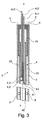
これらの欠点を緩和するために、本発明の発明者達は、例えば図3に示されたようなロッド状温度計(4)を製造する考えを持った。 In order to alleviate these drawbacks, the inventors of the present invention had the idea of manufacturing a rod-shaped thermometer (4) as shown in FIG. 3, for example.
本発明に従う該ロッド(4)は、熱電対の2つの金属の1つを構成する金属で作られた保護用被覆部(40)備えている。 The rod (4) according to the invention comprises a protective covering (40) made of a metal that constitutes one of the two metals of the thermocouple.
被覆部の金属とは異なる金属で作られ且つ熱電対の2つの金属のもう一方を構成する複数のワイヤ(4.1、4.2、4.3)は、該被覆部(40)の内側に収納されている。 A plurality of wires (4.1, 4.2, 4.3) made of a metal different from the metal of the covering portion and constituting the other of the two metals of the thermocouple are arranged inside the covering portion (40). It is stored in.
ワイヤ(4.1、4.2、4.3)の各々の端部の1つは、所与の熱電対の測定接合部を形成するように、被覆部の内側へ溶接され、ワイヤの溶接された端部は、被覆部の内側にある軸(X)に相対的な、軸方向かつ方位角方向の複数の位置に分布され、ワイヤの各々は、その端部の少なくとも1つを介して被覆部から出て行く。 One end of each of the wires (4.1, 4.2, 4.3) is welded to the inside of the sheath so as to form a measurement junction for a given thermocouple, The ends are distributed at a plurality of axial and azimuthal positions relative to the axis (X) inside the sheath, each of the wires passing through at least one of its ends Go out of the cover.
すなわち、1つのワイヤ(4.1、4.2、4.3)の1つの端部は、沸騰危機の検出の目的のために監視されなければならない、軸方向かつ方位角方向の各位置に溶接されている。 That is, one end of one wire (4.1, 4.2, 4.3) is at each axial and azimuthal position that must be monitored for the purpose of boiling crisis detection. Welded.
好ましくは、保護用被覆部(40)の金属およびワイヤ(4.1、4.2、4.3)の金属は、K‐タイプの熱電対を形成する。 Preferably, the metal of the protective covering (40) and the metal of the wires (4.1, 4.2, 4.3) form a K-type thermocouple.
金属ワイヤ(4.1、4.2、4.3)は、好ましくは、それらをお互いから及び被覆部(40)(接合部は別にして)から絶縁するために電気絶縁コーティングで被覆されている。 The metal wires (4.1, 4.2, 4.3) are preferably coated with an electrically insulating coating to insulate them from each other and from the coating (40) (apart from the joint). Yes.
図3に示されたように、被覆部は、好ましくは2つの部分(40、41)で作られ、大径上部部分は底部分のまわりでろう付けされている。該上部部分(41)は、こうしてアダプターを形成し且つそれをより容易に接続部(30)にフィットさせる。 As shown in FIG. 3, the covering is preferably made of two parts (40, 41), the large diameter upper part being brazed around the bottom part. The upper part (41) thus forms an adapter and makes it easier to fit into the connection (30).
本発明に従うロッド状温度計(4)を作るために、以下の仕方で進めることは有利に可能である;
‐ 2つの半管を形成するように、熱電対の2つの金属の1つを構成する金属で作られた管(40)を、2つの向かい合う母線に沿って長手方向に切断すること、
‐ 熱電対の2つの金属の1つを構成する金属で作られた複数のワイヤ(4.1、4.2、4.3)の各々の1の端部を、少なくとも1つの半管の内側へ溶接し、該溶接されたワイヤの端部は、軸方向かつ方位角方向の複数の位置に分布させられていること(図3)、および、
‐ 被覆部を形成する金属管を、各母線に沿う溶接によって再構成し、一方、複数の金属ワイヤは、被覆部からその端部の少なくとも1つを介して出るようにしておくこと。該ワイヤ(4.1、4.2、4.3)の端部の1つの、半管の少なくとも1つへの溶接は、アーク溶接によって実現され、そして再構成溶接はスポット溶接である。
In order to make a rod-shaped thermometer (4) according to the invention, it is advantageously possible to proceed in the following manner;
-Cutting the tube (40) made of the metal constituting one of the two metals of the thermocouple longitudinally along two opposing busbars so as to form two half tubes;
-One end of each of a plurality of wires (4.1, 4.2, 4.3) made of metal that constitutes one of the two metals of the thermocouple, inside the at least one half tube The ends of the welded wire are distributed at a plurality of axial and azimuthal positions (FIG. 3), and
The metal tube forming the sheath is reconstructed by welding along each bus bar, while the metal wires exit from the sheath through at least one of its ends. The welding of one of the ends of the wire (4.1, 4.2, 4.3) to at least one of the half tubes is achieved by arc welding and the reconstructive welding is spot welding.
対策は、再構成された金属管(40)の底部分にフィットする密封端部をろう付け又は溶接することにより作られうる。 A countermeasure can be made by brazing or welding a sealed end that fits the bottom portion of the reconstructed metal tube (40).
外側加熱被覆部(2)(図1の直接加熱装置(1))又は内部抵抗器(2)(図2の間接加熱装置(1))のどちらかの内側のロッド状温度計にフィットさせるために、熱電対の共通金属を形成する被覆部(40)は、この被加熱管(2)の内側に且つある間隔で配置され、該被覆部と該被加熱管との間の空間は加圧絶縁ガス(20)を充填され、且つ加圧絶縁ガスを充填された該空間は、1以上の電気絶縁要素(5)によって密封される。電気絶縁要素(5)で密封レベルを作り出すために、そのような要素は、セラミックのシムでありうる、金属/セラミック/金属の留め具は、一方でアダプター管(41)によって、かつ他方で管(2)によって有利に作られうる。さらに、ロッド状温度計(4)が機械的に管(2)内に保持されることを保証するために、アダプター管(41)と管(2)との間の機械的金属/金属継ぎ手を、電気絶縁シム(5)の下側に形成することは可能である。 To fit a rod-shaped thermometer inside either the outer heating coating (2) (direct heating device (1) in FIG. 1) or the internal resistor (2) (indirect heating device (1) in FIG. 2) In addition, the covering part (40) forming the common metal of the thermocouple is arranged inside the heated pipe (2) at a certain interval, and the space between the covering part and the heated pipe is pressurized. The space filled with insulating gas (20) and filled with pressurized insulating gas is sealed by one or more electrical insulating elements (5). In order to create a sealing level with the electrically insulating element (5), such an element can be a ceramic shim, the metal / ceramic / metal fastener is on the one hand by the adapter tube (41) and on the other hand (2) can be advantageously made. In addition, a mechanical metal / metal joint between the adapter tube (41) and the tube (2) is provided to ensure that the rod thermometer (4) is mechanically held in the tube (2). It can be formed under the electrical insulation shim (5).
短絡の危険を回避するために、被覆部(40)は、測定接合部の外側の領域内に、電気絶縁材料、例えばセラミックで作られたスペーサー又はシム(8)で実装される。被覆部(40)の外側へ固定されたこれらシム(8)は、被加熱管の内側で遊びがあるようにフィットさせられるために寸法付けられる。シム(8)と該管の内側との間の遊びは、熱膨張に対する許容によって増加された取り付け許容範囲に対応する。 In order to avoid the risk of a short circuit, the covering (40) is mounted in a region outside the measuring joint with a spacer or shim (8) made of an electrically insulating material, for example ceramic. These shims (8), fixed to the outside of the covering (40), are dimensioned in order to be fit so that there is play inside the heated tube. The play between the shim (8) and the inside of the tube corresponds to the mounting tolerance increased by the tolerance for thermal expansion.
測定器具の応答時間を改善するために、被加熱管(2)の内側面の放射率は、0.8の値を超えるように増加させられうる。同様に、被覆部の外側面の放射率は、0.8を超える値に増加させられうる。 In order to improve the response time of the measuring instrument, the emissivity of the inner surface of the heated tube (2) can be increased to exceed a value of 0.8. Similarly, the emissivity of the outer surface of the covering can be increased to a value greater than 0.8.
本発明に従うロッド状温度計の上部部分(41)において、密封部(9)は、金属ワイヤ(4.1、4.2、4.3)と上記ワイヤが位置を保持することをまた可能にする被覆部の(41)との間に形成されうる。 In the upper part (41) of the rod-shaped thermometer according to the invention, the sealing part (9) also allows the metal wire (4.1, 4.2, 4.3) and the wire to hold their position. And (41) of the covering portion to be formed.
実施例として、本発明に従う、全部そろった装置(1)およびロッド状温度計(4)の寸法および材料は以下に与えられている。 By way of example, the dimensions and materials of the complete device (1) and rod thermometer (4) according to the invention are given below.
寸法
- 完備の装置(1);
水面下の長さLn:1.2〜4.5m、
全長Lt:1.5〜4.8m、
- 外側被覆部(2又は7);
外径:8.5〜10.7mm、
厚さ:〜1mm(3.5MW/m2に等しいピーク電力束に対して0.5mmの値)、
- 抵抗器(2);
加熱される長さLc:1〜4.3m、
外径は被覆部(7)の内径よりも約0.5mmだけ小さい、
内径は問題となっている電気抵抗に依存する、
- セラミックペレット(6);
厚さ:約2mm、
- シム(8);
外径:4.9mm、
内径:4mm、
高さ:10mm、
- 本発明に従うロッド状温度計(4);
全長:1〜3m、
外径:4mm、
保護用被覆部(40);
厚さ:0.1mm、
金属ワイヤ(4.1、4.2、4.3、・・);
直径:0.1mm。
Size
-Complete equipment (1);
Underwater length Ln: 1.2-4.5 m,
Total length Lt: 1.5 to 4.8 m,
-Outer covering (2 or 7);
Outer diameter: 8.5 to 10.7 mm,
Thickness: ˜1 mm (0.5 mm value for peak power flux equal to 3.5 MW / m 2 ),
-Resistor (2);
Heated length Lc: 1 to 4.3 m,
The outer diameter is smaller by about 0.5 mm than the inner diameter of the covering portion (7),
The inner diameter depends on the electrical resistance in question,
-Ceramic pellets (6);
Thickness: about 2mm
-Shim (8);
Outer diameter: 4.9 mm,
Inner diameter: 4 mm,
Height: 10mm,
A rod-shaped thermometer (4) according to the invention;
Total length: 1-3m,
Outer diameter: 4mm,
Protective covering (40);
Thickness: 0.1mm,
Metal wires (4.1, 4.2, 4.3, ...);
Diameter: 0.1 mm.
材料
- 被覆部(7):Inconel 600又は316Lステンレス鋼、
- 抵抗器(2):Inconel 600又は70/30白銅、
- 堆積されたペレット(6)は、窒化ボロン又は窒化アルミニウム及びジルコニアで作られたセラミック被覆(22)で作られている、
- 電気的接続(30、31):銅、ニッケル又はシリコーン、
- 密封要素(5):一方で該管(2)に且つ他方でアダプター管(41)に留められたセラミックシム、
- 電気絶縁密封要素(9):樹脂又はシリコーン、
- シム(8):アルミナ又はジルコニア、
- 本発明に従うロッド状温度計(4):
保護用被覆部(40):クロメル又はInconel(商標)600、
ワイヤ(4.1、4.2、4.3):アルミナで被覆されたアルメル。
material
-Cover (7): Inconel 600 or 316L stainless steel,
-Resistor (2): Inconel 600 or 70/30 white copper,
The deposited pellets (6) are made of a ceramic coating (22) made of boron nitride or aluminum nitride and zirconia,
-Electrical connection (30, 31): copper, nickel or silicone,
Sealing element (5): a ceramic shim fastened to the tube (2) on the one hand and to the adapter tube (41) on the other hand,
-Electrical insulating sealing element (9): resin or silicone,
-Shim (8): alumina or zirconia,
-Rod thermometer according to the invention (4):
Protective coating (40): Chromel or Inconel ™ 600,
Wire (4.1, 4.2, 4.3): Alumel coated with alumina.
本発明に従うロッド状温度計(4)について指示された寸法および材料によって、該ロッド状温度計(4)の熱慣性は、相対的に低く、それにより、相対的に短い応答時間をもたらす。典型的には、1000℃/sの被覆部(2)の温度増加のために、10℃より高い設定検出閾値は、被覆部の温度が750℃未満に対して100ms未満以内に、ロッド状温度計(4)によって達せられる。 Due to the dimensions and materials indicated for the rod thermometer (4) according to the invention, the thermal inertia of the rod thermometer (4) is relatively low, thereby providing a relatively short response time. Typically, due to the temperature increase of the cover (2) of 1000 ° C./s, the set detection threshold higher than 10 ° C. is less than 100 ms for the cover temperature less than 750 ° C. Reached by total (4).
専ら、沸騰危機試験を実行するために核燃料棒を電気的にシミュレートするための装置について記載されたが、図2及び3を参照しつつ上に記載された本発明に従う装置はまた、より一般的に、軸方向かつ方位角方向において高い測定密度が要求される壁の温度の検出に用いられうる。 Although described exclusively for an apparatus for electrically simulating a nuclear fuel rod to perform a boiling crisis test, the apparatus according to the present invention described above with reference to FIGS. 2 and 3 is also more general. In particular, it can be used to detect the temperature of the wall, which requires a high measurement density in the axial direction and the azimuth direction.
1 電気的シミュレーション装置
2 抵抗器、被覆部、管
4 ロッド状温度計
4.1〜4.3 ワイヤ
5 端部プラグ
6 中間要素、セラミックペレットの円柱
7 被覆部
8 シム
9 密封部
20 被覆部の内側、空間
30、31 電気的接続部
40 保護用被覆部
41 アダプター管
DESCRIPTION OF SYMBOLS 1 Electrical simulation apparatus 2 Resistor, coating | covering part, pipe | tube 4 Rod-shaped thermometer 4.1-4.3
Claims (17)
- 温度を検知しうる複数の要素、
- 該検知しうる要素が部分的に収納されている長手方向軸Xを持つ保護用被覆部、
を備え、
該被覆部(40)は、熱電対の2つの金属の1つを構成する金属で作られていること、および該検知しうる要素は、該被覆部の該金属とは異なる金属で作られ且つ熱電対の該2つの金属の他方を構成する複数のワイヤ(4.1、4.2、4.3、・・)から成り、該ワイヤの各々の端部の1つは、所与の熱電対の測定接合部を形成するように該被覆部の内側部へ溶接され、該ワイヤの該溶接された端部は、該被覆部の該内側部で該軸Xに対して軸方向かつ方位角方向の複数の位置に分布され、該ワイヤの各々は、該被覆部からその端部の少なくとも1つを介して出ること、を特徴とする、上記ロッド状温度計。 A device for detecting the temperature, forming a rod-shaped thermometer (4),
-Multiple elements that can detect temperature,
A protective covering with a longitudinal axis X in which the detectable element is partially housed,
With
The covering (40) is made of a metal constituting one of the two metals of the thermocouple, and the detectable element is made of a metal different from the metal of the covering; and A plurality of wires (4.1, 4.2, 4.3,...) Constituting the other of the two metals of the thermocouple, one end of each of the wires being a given thermoelectric Welded to the inner side of the sheath to form a pair of measuring joints, the welded end of the wire being axially and azimuthally relative to the axis X at the inner portion of the sheath The rod-shaped thermometer according to claim 1, wherein the rod-shaped thermometer is distributed at a plurality of positions in a direction, and each of the wires exits from the covering portion through at least one of its ends.
‐ 2つの半管を形成するように、熱電対の2つの金属の1つを構成する金属で作られた管(40)を、2つの向かい合う母線に沿って長手方向に切断すること、
‐ 熱電対の2つの金属の1つを構成する金属で作られた複数のワイヤ(4.1、4.2、4.3、・・)の各々の1の端部を、少なくとも1つの半管の内側部へ溶接し、該溶接されたワイヤの該端部は、軸方向かつ方位角方向の複数の位置に分布させられていること、および
‐ 該金属管を、各母線に沿う溶接によって再構成して該被覆部を形成すること、一方、該複数の金属ワイヤは、該被覆部からその端部の少なくとも1つを介して出たままにしておくこと、
を包含する、上記製造方法。 It is a method for manufacturing this rod-shaped thermometer of any one of Claims 1-9, Comprising: The following processes;
-Cutting the tube (40) made of the metal constituting one of the two metals of the thermocouple longitudinally along two opposing busbars so as to form two half tubes;
-One end of each of a plurality of wires (4.1, 4.2, 4.3,...) Made of metal that constitutes one of the two metals of the thermocouple, at least one half Welding to the inside of the tube, the ends of the welded wire being distributed at a plurality of axial and azimuthal positions, and-the metal tube by welding along each bus Reconfiguring to form the covering, while leaving the plurality of metal wires out of the covering through at least one of its ends;
The said manufacturing method including.
The rod-shaped thermometer according to any one of claims 1 to 9, implemented using the method according to any one of claims 13 to 16 to detect the occurrence of a boiling crisis. how to use.
Applications Claiming Priority (3)
| Application Number | Priority Date | Filing Date | Title |
|---|---|---|---|
| FR1259890 | 2012-10-17 | ||
| FR1259890A FR2996914B1 (en) | 2012-10-17 | 2012-10-17 | TEMPERATURE DETECTION DEVICE FORMING THERMOMETRIC ROD, APPLICATION TO THE ELECTRICAL SIMULATION OF NUCLEAR FUEL PENCILS. |
| PCT/IB2013/059395 WO2014060966A2 (en) | 2012-10-17 | 2013-10-16 | Rod thermometer device for detecting a temperature, use for the electrical stimulation of nuclear fuel rods |
Publications (2)
| Publication Number | Publication Date |
|---|---|
| JP2015536447A true JP2015536447A (en) | 2015-12-21 |
| JP2015536447A5 JP2015536447A5 (en) | 2016-11-24 |
Family
ID=47356204
Family Applications (1)
| Application Number | Title | Priority Date | Filing Date |
|---|---|---|---|
| JP2015537399A Pending JP2015536447A (en) | 2012-10-17 | 2013-10-16 | Rod-type thermometer device for temperature detection, usage method for electric simulation of nuclear fuel rod |
Country Status (6)
| Country | Link |
|---|---|
| US (1) | US9835497B2 (en) |
| EP (1) | EP2909592B1 (en) |
| JP (1) | JP2015536447A (en) |
| KR (1) | KR20150065746A (en) |
| FR (1) | FR2996914B1 (en) |
| WO (1) | WO2014060966A2 (en) |
Families Citing this family (8)
| Publication number | Priority date | Publication date | Assignee | Title |
|---|---|---|---|---|
| FR2975527B1 (en) * | 2011-05-18 | 2013-07-05 | Commissariat Energie Atomique | DEVICE FOR ELECTRICALLY HEATING A LIQUID, ITS PRODUCTION METHOD AND APPLICATION TO THE ELECTRICAL SIMULATION OF NUCLEAR FUEL PENCILS |
| CN105241578A (en) * | 2015-07-22 | 2016-01-13 | 高淑珍 | Crude oil hierarchical temperature sensor, hierarchical temperature sensor, multi-functional crude oil detection device and online detection system |
| CN105788680A (en) * | 2016-03-30 | 2016-07-20 | 中国核动力研究设计院 | Heating simulation element for reactor core |
| CN106328226B (en) * | 2016-09-21 | 2018-01-30 | 中国核动力研究设计院 | A kind of electric heater unit and assembly technology for simulating nuclear reactor fuel rod |
| CN109238490B (en) * | 2018-09-13 | 2020-02-07 | 中国核动力研究设计院 | Temperature measuring method for small-diameter rod cluster assembly under motion condition |
| US11963268B2 (en) * | 2019-06-19 | 2024-04-16 | Oregon State University | Resistance heater rod and method of making such |
| FR3110242B1 (en) * | 2020-05-12 | 2022-06-03 | Commissariat Energie Atomique | Miniaturized system for determining the heat exchange coefficient and associated manufacturing method |
| CN114222383B (en) * | 2021-12-13 | 2023-02-17 | 西安交通大学 | High-temperature-resistant annular electric heating rod capable of measuring wall surface temperature field |
Citations (3)
| Publication number | Priority date | Publication date | Assignee | Title |
|---|---|---|---|---|
| JPS5915829A (en) * | 1982-07-19 | 1984-01-26 | Yamari Sangyo Kk | Tubular multipoint heat flowmeter |
| JPS6465425A (en) * | 1987-09-07 | 1989-03-10 | Toshiba Corp | Thermocouple |
| JPH09138293A (en) * | 1995-09-11 | 1997-05-27 | Atea Soc Atlantique De Technic Avancees | Hole detecting and observing device of bottom head of container of nuclear reactor formed by providing at least one thermocouple |
Family Cites Families (7)
| Publication number | Priority date | Publication date | Assignee | Title |
|---|---|---|---|---|
| IT555796A (en) | 1955-06-30 | |||
| GB1059860A (en) * | 1964-12-15 | 1967-02-22 | Atomic Energy Authority Uk | Improvements in or relating to thermocouples |
| US4326122A (en) * | 1980-07-14 | 1982-04-20 | The United States Of America As Represented By The United States Department Of Energy | Electric heater for nuclear fuel rod simulators |
| US4659898A (en) * | 1985-02-07 | 1987-04-21 | Westinghouse Electric Corp. | Method of attaching a thermocouple to a metal surface |
| GB0822734D0 (en) * | 2008-12-12 | 2009-01-21 | Environmental Monitoring And C | Method and apparatus for monitoring gas concentration |
| FR2975527B1 (en) | 2011-05-18 | 2013-07-05 | Commissariat Energie Atomique | DEVICE FOR ELECTRICALLY HEATING A LIQUID, ITS PRODUCTION METHOD AND APPLICATION TO THE ELECTRICAL SIMULATION OF NUCLEAR FUEL PENCILS |
| US20130083883A1 (en) * | 2011-10-04 | 2013-04-04 | Westinghouse Electric Company Llc | Pool level indication system |
-
2012
- 2012-10-17 FR FR1259890A patent/FR2996914B1/en active Active
-
2013
- 2013-10-16 WO PCT/IB2013/059395 patent/WO2014060966A2/en active Application Filing
- 2013-10-16 EP EP13818383.5A patent/EP2909592B1/en not_active Not-in-force
- 2013-10-16 KR KR1020157010394A patent/KR20150065746A/en not_active Application Discontinuation
- 2013-10-16 US US14/436,508 patent/US9835497B2/en not_active Expired - Fee Related
- 2013-10-16 JP JP2015537399A patent/JP2015536447A/en active Pending
Patent Citations (4)
| Publication number | Priority date | Publication date | Assignee | Title |
|---|---|---|---|---|
| JPS5915829A (en) * | 1982-07-19 | 1984-01-26 | Yamari Sangyo Kk | Tubular multipoint heat flowmeter |
| JPS6465425A (en) * | 1987-09-07 | 1989-03-10 | Toshiba Corp | Thermocouple |
| JPH09138293A (en) * | 1995-09-11 | 1997-05-27 | Atea Soc Atlantique De Technic Avancees | Hole detecting and observing device of bottom head of container of nuclear reactor formed by providing at least one thermocouple |
| US5712886A (en) * | 1995-09-11 | 1998-01-27 | Atea, Societe Atlantique De Techniques Avancees | Device for detecting and monitoring perforation of the bottom head of the vessel of a nuclear reactor |
Also Published As
| Publication number | Publication date |
|---|---|
| US9835497B2 (en) | 2017-12-05 |
| KR20150065746A (en) | 2015-06-15 |
| EP2909592B1 (en) | 2018-04-04 |
| EP2909592A2 (en) | 2015-08-26 |
| FR2996914A1 (en) | 2014-04-18 |
| US20150323390A1 (en) | 2015-11-12 |
| FR2996914B1 (en) | 2014-12-19 |
| WO2014060966A2 (en) | 2014-04-24 |
| WO2014060966A3 (en) | 2014-09-12 |
Similar Documents
| Publication | Publication Date | Title |
|---|---|---|
| JP2015536447A (en) | Rod-type thermometer device for temperature detection, usage method for electric simulation of nuclear fuel rod | |
| US9468041B2 (en) | Electrical heating device for heating a liquid, method for producing same, and use in the electrical simulation of nuclear fuel rods | |
| US4298430A (en) | Apparatus for determining the local power generation rate in a nuclear reactor fuel assembly | |
| CN111477366B (en) | Detector assembly integrating reactor core measuring function | |
| JP5740288B2 (en) | Reactor water level measurement system | |
| CN108917962B (en) | A kind of thin stick narrow gap wall temperature temperature measuring equipment under moving condition | |
| JP2014530364A (en) | Pool water level indication system | |
| US4393025A (en) | Method of and apparatus for measuring the power distribution in nuclear reactor cores | |
| JPS6161360B2 (en) | ||
| Ajay et al. | Experimental investigation of radiation heat transfer in coolant channel under impaired cooling scenario for Indian PHWR | |
| CN111326269A (en) | Reactor core measuring sensor based on self-powered detector and thermocouple | |
| Carcreff | CALMOS: Innovative device for the measurement of nuclear heating in material testing reactors | |
| Rempe et al. | New sensors for in-pile temperature measurement at the advanced test reactor national scientific user facility | |
| KR101071416B1 (en) | Capsule for high-temperature irradiation | |
| Xiong et al. | Experimental and analytical study on heat dissipation mechanisms during spent fuel unloading in sodium fast reactor | |
| CN104517657A (en) | Device for generating a high temperature gradient in a sample, including optical control means | |
| JP5784449B2 (en) | Water level measuring device | |
| CN205484146U (en) | Measurement device for be used for measuring hot rerum natura of article | |
| Wang et al. | Thermal conductivity measurements for simulated PWR crud | |
| KR101967582B1 (en) | Modular type experimental apparatus for critical heat flux of exterior surface in nuclear reactor | |
| US20210372957A1 (en) | Optical fiber-based gamma calorimeter (ofbgc) | |
| Nandan et al. | Thermo-mechanical behavior of pressure tube of Indian PHWR at 20 Bar pressure | |
| Nandan et al. | Experimental investigation of heat transfer during LOCA with failure of emergency cooling system | |
| KR101037359B1 (en) | Method for fixing temperature sensor and structure using same | |
| Lipka et al. | Experimental study of ISHTAR thermostatic irradiation device for the MARIA research reactor |
Legal Events
| Date | Code | Title | Description |
|---|---|---|---|
| A521 | Request for written amendment filed |
Free format text: JAPANESE INTERMEDIATE CODE: A523 Effective date: 20161004 |
|
| A621 | Written request for application examination |
Free format text: JAPANESE INTERMEDIATE CODE: A621 Effective date: 20161004 |
|
| A977 | Report on retrieval |
Free format text: JAPANESE INTERMEDIATE CODE: A971007 Effective date: 20170828 |
|
| A131 | Notification of reasons for refusal |
Free format text: JAPANESE INTERMEDIATE CODE: A131 Effective date: 20170927 |
|
| A521 | Request for written amendment filed |
Free format text: JAPANESE INTERMEDIATE CODE: A523 Effective date: 20171227 |
|
| A02 | Decision of refusal |
Free format text: JAPANESE INTERMEDIATE CODE: A02 Effective date: 20180611 |