JP2015532702A - Planetary gear reducer especially for turbomachinery - Google Patents
Planetary gear reducer especially for turbomachinery Download PDFInfo
- Publication number
- JP2015532702A JP2015532702A JP2015529106A JP2015529106A JP2015532702A JP 2015532702 A JP2015532702 A JP 2015532702A JP 2015529106 A JP2015529106 A JP 2015529106A JP 2015529106 A JP2015529106 A JP 2015529106A JP 2015532702 A JP2015532702 A JP 2015532702A
- Authority
- JP
- Japan
- Prior art keywords
- passage
- planet carrier
- sun gear
- elements
- outlet
- Prior art date
- Legal status (The legal status is an assumption and is not a legal conclusion. Google has not performed a legal analysis and makes no representation as to the accuracy of the status listed.)
- Granted
Links
Images


Classifications
-
- F—MECHANICAL ENGINEERING; LIGHTING; HEATING; WEAPONS; BLASTING
- F16—ENGINEERING ELEMENTS AND UNITS; GENERAL MEASURES FOR PRODUCING AND MAINTAINING EFFECTIVE FUNCTIONING OF MACHINES OR INSTALLATIONS; THERMAL INSULATION IN GENERAL
- F16H—GEARING
- F16H57/00—General details of gearing
- F16H57/04—Features relating to lubrication or cooling or heating
- F16H57/0467—Elements of gearings to be lubricated, cooled or heated
- F16H57/0479—Gears or bearings on planet carriers
-
- F—MECHANICAL ENGINEERING; LIGHTING; HEATING; WEAPONS; BLASTING
- F16—ENGINEERING ELEMENTS AND UNITS; GENERAL MEASURES FOR PRODUCING AND MAINTAINING EFFECTIVE FUNCTIONING OF MACHINES OR INSTALLATIONS; THERMAL INSULATION IN GENERAL
- F16H—GEARING
- F16H57/00—General details of gearing
- F16H57/04—Features relating to lubrication or cooling or heating
- F16H57/0434—Features relating to lubrication or cooling or heating relating to lubrication supply, e.g. pumps ; Pressure control
- F16H57/0442—Features relating to lubrication or cooling or heating relating to lubrication supply, e.g. pumps ; Pressure control for supply in case of failure, i.e. auxiliary supply
-
- F—MECHANICAL ENGINEERING; LIGHTING; HEATING; WEAPONS; BLASTING
- F16—ENGINEERING ELEMENTS AND UNITS; GENERAL MEASURES FOR PRODUCING AND MAINTAINING EFFECTIVE FUNCTIONING OF MACHINES OR INSTALLATIONS; THERMAL INSULATION IN GENERAL
- F16H—GEARING
- F16H57/00—General details of gearing
- F16H57/04—Features relating to lubrication or cooling or heating
- F16H57/0434—Features relating to lubrication or cooling or heating relating to lubrication supply, e.g. pumps ; Pressure control
- F16H57/0435—Pressure control for supplying lubricant; Circuits or valves therefor
-
- F—MECHANICAL ENGINEERING; LIGHTING; HEATING; WEAPONS; BLASTING
- F16—ENGINEERING ELEMENTS AND UNITS; GENERAL MEASURES FOR PRODUCING AND MAINTAINING EFFECTIVE FUNCTIONING OF MACHINES OR INSTALLATIONS; THERMAL INSULATION IN GENERAL
- F16H—GEARING
- F16H57/00—General details of gearing
- F16H57/04—Features relating to lubrication or cooling or heating
- F16H57/045—Lubricant storage reservoirs, e.g. reservoirs in addition to a gear sump for collecting lubricant in the upper part of a gear case
-
- F—MECHANICAL ENGINEERING; LIGHTING; HEATING; WEAPONS; BLASTING
- F16—ENGINEERING ELEMENTS AND UNITS; GENERAL MEASURES FOR PRODUCING AND MAINTAINING EFFECTIVE FUNCTIONING OF MACHINES OR INSTALLATIONS; THERMAL INSULATION IN GENERAL
- F16H—GEARING
- F16H57/00—General details of gearing
- F16H57/04—Features relating to lubrication or cooling or heating
- F16H57/048—Type of gearings to be lubricated, cooled or heated
- F16H57/0482—Gearings with gears having orbital motion
- F16H57/0486—Gearings with gears having orbital motion with fixed gear ratio
-
- F—MECHANICAL ENGINEERING; LIGHTING; HEATING; WEAPONS; BLASTING
- F16—ENGINEERING ELEMENTS AND UNITS; GENERAL MEASURES FOR PRODUCING AND MAINTAINING EFFECTIVE FUNCTIONING OF MACHINES OR INSTALLATIONS; THERMAL INSULATION IN GENERAL
- F16H—GEARING
- F16H57/00—General details of gearing
- F16H57/04—Features relating to lubrication or cooling or heating
Abstract
本発明は、とりわけターボ機械用の遊星歯車減速機に関し、遊星歯車減速機は、少なくとも2つの要素(22)を積み重ねることによって生ずる、圧力降下を発生させることが可能な流体循環通路(20a、20b)を形成する装置を装備する。各要素(22)は流体を運ぶための通路(27)を備え、通路は、圧力降下を発生させることが可能であり、入口(28)および出口(29)を備える。一方の要素(22)の通路(27)の出口(29)または入口(28)はそれぞれ、他方の要素(22)の通路(27)の入口(28)または出口(29)に接続されている。The present invention relates to a planetary gear reducer, in particular for turbomachines, which is a fluid circulation passage (20a, 20b) capable of generating a pressure drop caused by stacking at least two elements (22). Equip equipment to form). Each element (22) comprises a passage (27) for carrying a fluid, the passage being capable of generating a pressure drop and comprising an inlet (28) and an outlet (29). The outlet (29) or inlet (28) of the passage (27) of one element (22) is connected to the inlet (28) or outlet (29) of the passage (27) of the other element (22), respectively. .
Description
本発明は、圧力降下を発生させるようになされた流体循環通路を形成する装置を備える、特にターボ機械用の遊星歯車減速機に関する。 The present invention relates to a planetary gear reducer, in particular for a turbomachine, comprising a device for forming a fluid circulation passage adapted to generate a pressure drop.
遊星歯車は従来、同軸の内部太陽歯車および外部太陽歯車を備え、内部太陽歯車はその軸を中心に回転可能であり、外部太陽歯車は静止しており、少なくとも1つの遊星歯車は遊星キャリア上で回転して移動可能であるように装着され内部太陽歯車および外部太陽歯車の両方と噛み合い、遊星キャリアは内部太陽歯車および外部太陽歯車の軸を中心に旋回することが可能である。入口は典型的には、内部太陽歯車によって形成され、出口は遊星キャリアによって形成される。外遊星は軌道歯車とも称される。 A planetary gear conventionally comprises a coaxial internal sun gear and an external sun gear, the internal sun gear is rotatable about its axis, the external sun gear is stationary, and at least one planet gear is on the planet carrier. Mounted to rotate and move and mesh with both the internal and external sun gears, the planet carrier can pivot about the axes of the internal and external sun gears. The inlet is typically formed by an internal sun gear and the outlet is formed by a planet carrier. An outer planet is also called an orbital gear.
ターボ機械において、遊星歯車減速機は特に、タービンの回転速度に関わらず、ファンロータの回転速度を減速させるための減速装置として使用される。 In a turbomachine, the planetary gear reducer is used as a speed reducer for reducing the rotational speed of the fan rotor regardless of the rotational speed of the turbine.
欧州特許第1703174号明細書はこのような遊星歯車減速機を記載しており、そこでは、遊星歯車を形成する鎖歯車がジャーナル軸受によって遊星キャリアのピボット上に装着されている。言い換えると、遊星キャリアは、遊星歯車の円筒形の孔の中に係合した円筒形のピボットを備える。減速装置は、前記円筒形表面の間の境界面において開口する油供給通路をさらに備える。作動時、焼き付きを防止するために、油の層が境界面に存在しなければならない。 EP 1703174 describes such a planetary gear reducer, in which the chain gear forming the planetary gear is mounted on the planet carrier pivot by means of a journal bearing. In other words, the planet carrier comprises a cylindrical pivot engaged in a cylindrical hole in the planet gear. The speed reducer further comprises an oil supply passage that opens at the interface between the cylindrical surfaces. In operation, a layer of oil must be present at the interface to prevent seizure.
ジャーナル軸受は一般的に、転動体を使用する軸受よりも軽く、嵩張らず、信頼性が高く、ジャーナル軸受は、絶えず油が供給され油が研磨粒子を含まない限り、ほぼ無限の耐用年数を有する。 Journal bearings are generally lighter, less bulky and more reliable than bearings using rolling elements, and journal bearings have an almost infinite service life unless oil is constantly supplied and the oil contains abrasive particles. .
油供給回路における故障の場合、たとえばポンプ故障の場合、ジャーナル軸受への油の供給は、たとえば補助ポンプを始動させるのにまたはターボ機械を停止するのに十分長く維持されなければならない。この期間はたとえば数十秒になる。 In case of a failure in the oil supply circuit, for example in the case of a pump failure, the supply of oil to the journal bearings must be maintained long enough to start the auxiliary pump or to stop the turbomachine, for example. This period is, for example, several tens of seconds.
このために、欧州特許第1703174号明細書は、遊星キャリア内のアキュムレータの形成を提供し、各アキュムレータは所与の持続時間にわたって故障の場合にジャーナル軸受に油を供給することが可能である。このようなアキュムレータの構造およびその場所は、遊星キャリアの生産を困難にし、その寸法および質量を増加させる。 To this end, EP 1703174 provides for the formation of accumulators in a planetary carrier, each accumulator being able to supply the journal bearing in the event of a failure for a given duration. Such an accumulator structure and its location make it difficult to produce planet carriers and increases its size and mass.
また、機能停止の場合にジャーナル軸受に供給される油の流れを制御することは、比較的困難である。特に、焼き付きを防止するのに十分でありながら、十分に長い時間にわたって油を供給することが可能であるように、比較的低い流量であるべきである。 In addition, it is relatively difficult to control the flow of oil supplied to the journal bearing when the function is stopped. In particular, the flow rate should be relatively low so that the oil can be supplied for a sufficiently long time while being sufficient to prevent seizure.
小さい直径を有する通路が一般的に、流体流量を制限するために使用される。しかしながらこの用途では、比較的長い長さ(たとえば、通路の直径のおよそ100倍の長さ)にわたって十分に小さい直径を有する通路は、実現するのが困難であるばかりでなく、油回路に含まれた粒子による閉塞も受ける。別の解決策は、流量を制限するように通路の入口でろ過器を使用することであり得るが、この場合も、粒子によるろ過器の閉塞の危険性が存在する。 A passage having a small diameter is typically used to limit fluid flow. However, in this application, a passage having a sufficiently small diameter over a relatively long length (eg, about 100 times the diameter of the passage) is not only difficult to achieve, but is also included in the oil circuit. Occluded by particles. Another solution could be to use a filter at the entrance to the passage to limit the flow, but again there is a risk of clogging the filter by particles.
本発明はより具体的には、この問題に対する単純で効率的な費用効果の高い解決策を提供することを目的とする。 The present invention more specifically aims to provide a simple, efficient and cost effective solution to this problem.
このために、本発明は、少なくとも2つの要素を積み重ねることによって生ずる、圧力降下を発生させるようになされた流体循環通路を形成する装置を提供し、各要素は、圧力降下を発生させるようになされており入口および出口を備える流体循環通路を備え、一方の要素の通路の出口および入口はそれぞれ、他方の要素の通路の入口および出口にそれぞれ接続されている。 To this end, the present invention provides an apparatus for forming a fluid circulation passage adapted to generate a pressure drop caused by stacking at least two elements, each element being adapted to generate a pressure drop. And a fluid circulation passage having an inlet and an outlet, the outlet and the inlet of the passage of one element being connected to the inlet and the outlet of the passage of the other element, respectively.
このような個々の要素は容易に達成され、組み立て後に様々な組み立て済み要素の一連の通路から形成された連続する通路を形成する。要素の数が多いほど、装置の通路内の圧力降下が大きくなる。加えて、各要素の通路は必ずしも非常に小さい断面を有するとは限らず、これは、流体中に存在する粒子による装置の閉塞を防止することを可能にする。 Such individual elements are easily achieved and form a continuous passage formed from a series of passages of various assembled elements after assembly. The greater the number of elements, the greater the pressure drop in the device passage. In addition, the passage of each element does not necessarily have a very small cross section, which makes it possible to prevent the device from being blocked by particles present in the fluid.
装置は好ましくは、互いに対して要素を位置決めするための手段を備える。 The apparatus preferably comprises means for positioning the elements relative to each other.
次いで要素のうちの少なくとも1つは、隣接要素の相補的陥凹と協働する心だしピンを含んでもよい。 At least one of the elements may then include a centering pin that cooperates with a complementary recess in the adjacent element.
このため要素の通路の入口または出口は、隣接要素の通路の出口または入口に対向するように保証される。このため装置の通路の連続性が確保される。 Thus, the entry or exit of an element passage is guaranteed to face the exit or entry of an adjacent element passage. For this reason, the continuity of the passage of the apparatus is ensured.
有利には、各要素の通路は全体的に迷路の形状を有し少なくとも1つの屈曲領域を備え、これは、通路断面を小さくする必要を伴わずに圧力降下を増加させることを可能にする。 Advantageously, the passage of each element has an overall labyrinth shape and is provided with at least one bent region, which makes it possible to increase the pressure drop without having to reduce the passage cross section.
本発明の一実施形態によれば、要素のうちの少なくとも1つの通路は、粒子を捕捉するように意図された陥凹を有する。 According to one embodiment of the invention, the passage of at least one of the elements has a recess intended to trap particles.
このため粒子は装置によって捕捉され、たとえばジャーナル軸受において、下流で排出される。 For this, the particles are captured by the device and discharged downstream, for example in a journal bearing.
加えて、各要素は2つの反対側の表面を備えてもよく、通路は一方の表面に形成され、通路の入口または出口は、前記要素を通り他方の表面上に開口する孔を備える。 In addition, each element may comprise two opposite surfaces, the passage being formed in one surface, the inlet or outlet of the passage comprising a hole passing through said element and on the other surface.
このような構造を有する要素は、比較的製造しやすい。 An element having such a structure is relatively easy to manufacture.
加えて、装置は同じ構造を有するいくつかの円筒形要素を備えてもよく、各前記要素の通路の入口および出口は所定の角度で角度的に離間しており、位置決め手段は同じ角度値で2つの隣接要素を角度的にずらすことを可能にする。 In addition, the device may comprise several cylindrical elements having the same structure, the inlet and outlet of the passage of each said element being angularly spaced by a predetermined angle, and the positioning means at the same angular value Allows two adjacent elements to be angularly displaced.
本発明は、同軸の内部太陽歯車および外部太陽歯車を備える、特にターボ機械用の遊星歯車減速機であり、内部太陽歯車はその軸を中心に回転可能であり、外部太陽歯車は静止しており、少なくとも1つの遊星歯車は遊星キャリア上で回転して移動可能であるように装着され内部太陽歯車および外部太陽歯車の両方と噛み合い、遊星キャリアは内部太陽歯車および外部太陽歯車の軸を中心に旋回することが可能であり、遊星歯車は、遊星キャリアの円筒形表面の周りを回転して移動可能であるように装着された円筒形の内表面を有し、減速機は、前記円筒形表面の間の境界面に油を供給するための手段をさらに備える、遊星歯車減速機であって、油供給手段はチャンバを備え、チャンバは、遊星キャリア内に設けられ、油のバッファ容積を形成するように意図され、遊星キャリアの回転軸から離間したいわゆる下部域と、遊星キャリアの回転軸に近いいわゆる上部域と、前記境界面および上部域において開口する少なくとも1つの主要通路と、前記境界面および下部域において開口する少なくとも1つの二次通路とを有し、前記二次通路は上述のタイプの装置を備えることを特徴とする遊星歯車減速機にさらに関する。 The present invention is a planetary gear reducer, particularly for turbomachines, comprising coaxial internal sun gears and external sun gears, the internal sun gear being rotatable about its axis and the external sun gear being stationary The at least one planetary gear is mounted to rotate and move on the planet carrier and meshes with both the internal sun gear and the external sun gear, the planet carrier pivots about the axis of the internal sun gear and the external sun gear The planetary gear has a cylindrical inner surface mounted so as to be rotatable about the cylindrical surface of the planet carrier, and the speed reducer A planetary gear reducer further comprising means for supplying oil to the interface between the oil supply means comprising a chamber, the chamber being provided in the planet carrier and forming an oil buffer volume. A so-called lower region which is intended to be spaced apart from the rotation axis of the planet carrier, a so-called upper region close to the rotation axis of the planet carrier, the boundary surface and at least one main passage opening in the upper region, and the boundary surface And at least one secondary passage opening in the lower region, said secondary passage further comprising a planetary gear reducer comprising a device of the type described above.
作動時、遠心力の効果の下で、チャンバ内に存在する油は半径方向外向きに押しやられる。したがって、遊星キャリア内に設けられたチャンバは、最初に遊星キャリアの回転軸から離間した下部領域内を満たし、次いで上部領域内を満たす。 In operation, under the effect of centrifugal force, the oil present in the chamber is pushed radially outward. Accordingly, the chamber provided in the planet carrier first fills in the lower region spaced from the rotation axis of the planet carrier, and then fills the upper region.
通常作動時、すなわち油供給回路内に故障がない際、チャンバに入る油の流れは多く、このため油面は前記チャンバの上部領域に到達する。油は次いで、ジャーナル軸受に、すなわち遊星キャリアの円筒形表面と遊星歯車の円筒形表面との間の境界面に供給するために、主要通路を通って流出することができる。 During normal operation, i.e., when there is no failure in the oil supply circuit, there is a lot of oil flowing into the chamber, so that the oil level reaches the upper region of the chamber. The oil can then flow out through the main passage to feed the journal bearing, i.e. the interface between the cylindrical surface of the planet carrier and the cylindrical surface of the planetary gear.
そのサイズを考慮すると、二次通路は、通常作動時チャンバが満たされるように、すべての油を流れさせるものではないことに留意されたい。 In view of its size, it should be noted that the secondary passage does not allow all oil to flow so that the chamber is normally filled during operation.
故障の場合、チャンバに入る油の流れはゼロになり、チャンバ内の油量は減少し、もはや上部領域に到達しない:油はもはや主要通路を通って流出せず、二次通路のみを通って流出することができる。ジャーナル軸受に供給する油の流れはこのため減少するが、たとえば補助ポンプを始動させるのにまたはターボ機械を停止するのに必要な制限された期間にわたって、軸受の焼き付きを防止するのに十分である(ジャーナル軸受の劣化作動)。 In case of failure, the flow of oil entering the chamber is zero, the amount of oil in the chamber is reduced and no longer reaches the upper region: the oil no longer flows through the main passage, only through the secondary passage Can be spilled. The flow of oil supplied to the journal bearing is thus reduced, but is sufficient to prevent bearing seizure, for example, for the limited period required to start the auxiliary pump or to stop the turbomachine. (Deterioration operation of journal bearing).
本発明は、油に含まれた粒子による二次通路の閉塞の危険性を回避しながら、故障の場合に油の低流量を発生させるのに十分に高い制御された圧力損失を有する二次通路を提供することをさらに可能にする。 The present invention relates to a secondary passage having a controlled pressure drop high enough to generate a low flow of oil in the event of a failure while avoiding the risk of blockage of the secondary passage by particles contained in the oil. Make it possible to provide further.
陥凹は好ましくは、遠心分離によって粒子を捕捉することが可能であるように、遊星キャリアの回転軸と反対の方向に、対応する要素の通路から延在する。 The recess preferably extends from the passage of the corresponding element in a direction opposite to the axis of rotation of the planet carrier so that particles can be captured by centrifugation.
加えて、各要素は、遊星キャリアの回転軸に対面する第1の表面と、第1の表面に反対側の第2の表面とを有し、各要素の通路は第1の表面に形成され、前記通路の出口は、前記要素を通り第2の表面上に開口する孔を有する。 In addition, each element has a first surface facing the rotational axis of the planet carrier and a second surface opposite the first surface, and the passage of each element is formed in the first surface. The outlet of the passage has a hole that opens through the element and onto the second surface.
以下の添付図面を参照しながら、非限定例によって与えられる以下の説明を読むと、本発明はより良く理解され、本発明のその他の詳細、特徴、および利点は明らかとなる。 The invention will be better understood and other details, features and advantages of the invention will become apparent upon reading the following description given by way of non-limiting example with reference to the accompanying drawings in which:
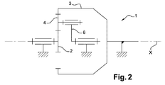
図1および図2は、本発明による遊星歯車減速機1の構造を概略的に示す。遊星歯車減速機は従来、同軸の内部太陽歯車2(太陽とも称される)および外部太陽歯車3(軌道歯車とも称される)を備える。内部太陽歯車2はその軸を中心に回転可能であり、外部太陽歯車3は静止している。減速機は、遊星キャリア6のピボット5上で回転して移動可能であるように装着された遊星歯車4をさらに備える。各遊星歯車4は、内部太陽歯車2および外部太陽歯車3の両方と噛み合う。遊星キャリア6は、内部太陽歯車2および外部太陽歯車3の軸Xを中心に旋回することが可能である。
1 and 2 schematically show the structure of a
入口は内部太陽歯車2によって形成され、出口は遊星キャリア6によって形成される。
The inlet is formed by the
ターボ機械において、遊星歯車減速機は特に、タービンの回転速度に関わらず、ファンロータの回転速度を減速させるための減速装置として使用される。 In a turbomachine, the planetary gear reducer is used as a speed reducer for reducing the rotational speed of the fan rotor regardless of the rotational speed of the turbine.
図3から図5において最も良くわかるように、各遊星歯車4は、ジャーナル軸受を形成するように、遊星キャリア6に対応するピボット5の円筒形表面8を中心に旋回するように装着された円筒形の内表面7を含む。
As best seen in FIGS. 3-5, each
したがって2つの円筒形表面7、8の間の境界面9には、油が供給されなければならない。このために、減速機1は、各ピボット5のY軸に沿って実質的に延在するチャンバ10を備える供給手段を備え、チャンバ10の少なくとも一方の端11は、油入口通路に接続されている。一方の端11のみが油入口を形成する場合には、他方の端は塞がれている。
Therefore, oil must be supplied to the interface 9 between the two
チャンバ10は全体的に円筒形であり、より特に、半径方向に延在する中央隔壁12によって分離された2つの部分10a、10bを備える。チャンバ10の側端11には、チャンバ10よりも小さい直径を有する孔が設けられており、少なくとも1つのこのような孔は、上記で示されたように油入口を形成する。
The
参照番号13が付された線は、チャンバ10のいわゆる下部点、すなわち遊星キャリア6の回転軸から最も離れた点を形成する。逆に、参照番号14が付された線はチャンバ10のいわゆる上部点、すなわち遊星キャリア6のX回転軸に最も近い点を形成する。同様に、いわゆる上部領域および下部領域は、それぞれ参照番号15および16が付されている。X軸は、図3のA断面内にあるが、図3から図5には示されていない。
The line marked with
作動時、遊星キャリア6の回転によって発生する遠心力の効果の下で、油は半径方向外向きに押されてチャンバ10内に戻される。したがって、最初にチャンバ10の下部領域15が満たされ、次いで上部領域16が満たされる。
In operation, under the effect of the centrifugal force generated by the rotation of the
チャンバ10の部分10a、10bの上部領域16内に向かって開口する孔17は、中心壁12を通る。チャンバ10の部分10a、10bの下部領域15内に開口する2つの孔18は、中心壁12をさらに通る。孔18は、図3のA平面の両側に、すなわち遊星キャリア6のX回転軸を通過しチャンバ10および対応するピボット5のY軸を通過する半径方向平面の両側に位置する。各孔18の直径は、孔17の直径よりも小さくてもよい。
A
主要通路19は、中央隔壁12内に半径方向に延在し、ピボット5の外側円筒壁8および孔17において開口する。
The
図3から図5の実施形態において、チャンバ10の各部分10a、10bは二次通路20a、20bをさらに備え、二次通路は、半径方向に延在しピボット5の外側円筒壁8において開口し、チャンバ10の対応する部分10a、10bの下部点13において開口する。
In the embodiment of FIGS. 3 to 5, each
各二次通路20a、20bの断面は、主要通路19の断面よりも小さい。
The cross sections of the
通常作動時、油は、油面がチャンバ10の上部領域16内に位置するのに十分な流量でチャンバ10に入る。油量は、孔18に起因してかつ孔17により、チャンバ10の両方の部分10a、10b内で等しい。
During normal operation, the oil enters the
次いで油は主要通路19に入り、遠心分離によって境界面9に供給される。
The oil then enters the
主要通路19の断面は、ジャーナル軸受の正確な作動を得ていかなる焼き付き現象も回避するように課されたまたは計算された仕様に厚さが対応する油膜を境界面9において得るようなサイズになされる。
The cross section of the
故障の場合、油量は、図3の参照番号21が付されたレベルに到達するまで急速に減少し、そこからは油はもはや孔17を通って主要通路19に入ることができない。この時から、油は二次通路20a、20bを通らなければ(遠心分離の効果の下で)流出することができない。劣化作動のこの段階の間、たとえば30秒程度の所与の期間にわたってジャーナル軸受の焼き付きを防止するように、十分な量の油が二次通路20a、20bを介して境界面9に到達する。この期間は、たとえば補助ポンプの再始動またはエンジンの停止を可能にするのに十分でなければならない。このため二次通路20a、20bの断面は、所望の時間にわたってこのような劣化モードを許容するように決定される。
In the event of a failure, the amount of oil decreases rapidly until it reaches the level marked with
図6から図9において最も良くわかるように、各二次通路20a、20bは、複数の同一要素22の積み重ねを備える装置によって形成され、要素22の構造は、図7および図8に示されている。
As best seen in FIGS. 6-9, each
各要素22は、全体的に円筒形の形状を有し、遊星キャリア6のX回転軸から離れたいわゆる下面23と、X軸に近いいわゆる反対側の上面24とを備える。いずれの面23、24も、互いに平行である。各要素22の軸は、参照符号Zが付されている。
Each
心だしピン25は上面24から突起し、一致する形状を有する陥凹26は下面23に形成される。あるいは、その逆が提供されてもよい。
The centering
通路27が、要素22の厚み部分の上面24にさらに形成される。通路27は、全体的に長方形または正方形の断面を有する。通路は、参照番号30、31、32がそれぞれ付された第1、第2、および第3の連続的直線部分によって接続された入口28および出口29を備える。第1の部分30は、入口28に接続されている。第2の部分31は、第1の屈曲を形成するように、第1の部分30に対して実質的に直角に延在する。同様に、第3の部分32は、第2の屈曲を形成するために第2の部分31に対して実質的に直角に延在する。第3の部分32は出口29にさらに接続されている。出口は、要素22を通り要素22の下面23において開口する孔によって形成される。
A
第1の部分30および第2の部分31は各々、対応する部分30、31の全幅にわたって延在する陥凹33を備える。各陥凹33は、通路27の底部から下面23に向かって延在する。
The
各陥凹33の底壁は、要素22の下面23および上面24に対して全体的に傾斜していてもよく、次いで最も深い陥凹領域は、入口28側に位置する。
The bottom wall of each
通路27の入口28および出口29は、Z軸に対して角度αで互いに対して角度的にずらされている。図示された例において、この角度αは90°程度の角度である。ピン25および陥凹26もまた、同じ角度値αでずらされている。
The
上記に示されたように、装置はいくつかの同一要素22を積み重ねることによって実現される。このため要素22のピン25は隣接要素22の陥凹26の中に係合し、要素22の通路27の出口29は隣接要素22の通路27の入口28に向かい合って位置して、連続する二次通路20a、20bを形成する。
As indicated above, the device is realized by stacking several
積み重ねの端に位置決めされた要素22が、互いに異なる構造を有してもよいことに留意されたい。実際のところ、前記いわゆる上部要素、すなわちX軸に最も近い積み重ねの要素は、ピン25を有さなくてもよい。加えて、いわゆる下部要素、すなわちX軸から最も遠い要素は、陥凹26を有さなくてもよい。
Note that the
加えて、積み重ねられた様々な要素22は、たとえば反対側のショルダおよびフランジからなるシステム、サークリップタイプの停止手段、またはネジシステムなどの適切な締結手段(図示せず)を使用して保持できる。代替解決策において、要素22は、ピボット5の孔の中で収縮することができる。このような締結手段は、二次通路20a、20bのある程度のきつさを確保するように、様々な要素22の下面23および上面24を接触した状態で維持することを可能にする。
In addition, the various
作動時、機能停止の間、図9の矢印34によって示されたように、油は上部要素22の入口28を通って入り、様々な連続的要素22の通路27の中で前方に移動し、境界面9に供給するように要素22の下部出口29を通って流出する。要素22の連続的屈曲は、油に含まれた粒子によるいかなる閉塞も回避するために十分に大きい通路断面を有しながら、二次通路20a、20b内の制限された油の流れを得るように、圧力降下を生じさせる。また、作動時、このような粒子は、これらが境界面9に引き込まれるのを回避するように、遠心分離33によって陥凹内に捕捉される。
In operation, during an outage, the oil enters through the
Claims (9)
Applications Claiming Priority (3)
| Application Number | Priority Date | Filing Date | Title |
|---|---|---|---|
| FR1258231 | 2012-09-04 | ||
| FR1258231 | 2012-09-04 | ||
| PCT/FR2013/052016 WO2014037659A1 (en) | 2012-09-04 | 2013-09-03 | Epicyclic reduction gear, notably for turbomachine |
Publications (2)
| Publication Number | Publication Date |
|---|---|
| JP2015532702A true JP2015532702A (en) | 2015-11-12 |
| JP6334535B2 JP6334535B2 (en) | 2018-05-30 |
Family
ID=47178129
Family Applications (1)
| Application Number | Title | Priority Date | Filing Date |
|---|---|---|---|
| JP2015529106A Expired - Fee Related JP6334535B2 (en) | 2012-09-04 | 2013-09-03 | Planetary gear reducer especially for turbomachinery |
Country Status (9)
| Country | Link |
|---|---|
| US (1) | US9429225B2 (en) |
| EP (1) | EP2893222B1 (en) |
| JP (1) | JP6334535B2 (en) |
| CN (1) | CN104641151B (en) |
| BR (1) | BR112015003826B1 (en) |
| CA (1) | CA2882383C (en) |
| ES (1) | ES2623180T3 (en) |
| RU (1) | RU2631739C2 (en) |
| WO (1) | WO2014037659A1 (en) |
Cited By (1)
| Publication number | Priority date | Publication date | Assignee | Title |
|---|---|---|---|---|
| CN106594246A (en) * | 2016-11-17 | 2017-04-26 | 杭州前进齿轮箱集团股份有限公司 | Lubrication and oil distribution device for high-speed gearbox |
Families Citing this family (12)
| Publication number | Priority date | Publication date | Assignee | Title |
|---|---|---|---|---|
| FR2995055B1 (en) * | 2012-09-04 | 2014-09-26 | Hispano Suiza Sa | REDUCER WITH EPICYCLOIDAL TRAIN, IN PARTICULAR FOR TURBOMACHINE |
| US9879608B2 (en) * | 2014-03-17 | 2018-01-30 | United Technologies Corporation | Oil loss protection for a fan drive gear system |
| FR3035375B1 (en) * | 2015-04-23 | 2018-07-27 | Safran Aircraft Engines | EPICYCLOIDAL GEAR TRAIN REDUCER FOR A TURBOMACHINE. |
| FR3042568B1 (en) * | 2015-10-16 | 2017-11-10 | Hispano-Suiza | TOOTHED CROWN FOR EPICYCLOIDAL REDUCER |
| US10494998B2 (en) * | 2017-01-30 | 2019-12-03 | United Technologies Corporation | Lubrication of epicyclic gear system for gas turbine engine |
| FR3082266B1 (en) | 2018-06-12 | 2020-06-19 | Safran Aircraft Engines | OIL DISTRIBUTION DEVICE FOR A ROTATING SATELLITE HOLDER OF A MECHANICAL REDUCER OF A TURBOMACHINE |
| FR3082265B1 (en) | 2018-06-12 | 2020-05-15 | Safran Aircraft Engines | ROTATING SATELLITE HOLDER FOR A MECHANICAL REDUCER OF A TURBOMACHINE |
| DE102018218932A1 (en) * | 2018-11-07 | 2020-05-07 | Zf Friedrichshafen Ag | Cooled planet bolt |
| FR3095252B1 (en) * | 2019-04-19 | 2021-05-14 | Safran Trans Systems | AIRCRAFT TURBOMACHINE MECHANICAL REDUCER |
| FR3101129B1 (en) | 2019-09-24 | 2021-08-27 | Safran Trans Systems | OIL RESTRICTOR FOR EMERGENCY LUBRICATION OF AN AIRCRAFT TURBOMACHINE ELEMENT |
| DE102020122584A1 (en) | 2020-08-28 | 2022-03-03 | Rolls-Royce Deutschland Ltd & Co Kg | Plain bearing for a planetary gear, planetary gear for a gas turbine engine and gas turbine engine |
| FR3132333A1 (en) | 2022-01-28 | 2023-08-04 | Safran Transmission Systems | SLIDING BEARING FOR AN AIRCRAFT TURBOMACHINE |
Citations (3)
| Publication number | Priority date | Publication date | Assignee | Title |
|---|---|---|---|---|
| JPS5517788A (en) * | 1978-07-11 | 1980-02-07 | Rolls Royce | Lubricant oil feeding device |
| JP2009209794A (en) * | 2008-03-04 | 2009-09-17 | Denso Corp | Valve-timing adjusting device |
| JP2010540937A (en) * | 2007-09-28 | 2010-12-24 | サーコア・インストルメンテーション・テクノロジーズ・インコーポレーテッド | Unclogged flow restrictor for pressure-based flow controllers |
Family Cites Families (15)
| Publication number | Priority date | Publication date | Assignee | Title |
|---|---|---|---|---|
| GB1130254A (en) | 1965-11-13 | 1968-10-16 | Rheinstahl Huettenwerke Ag | An improvement in or relating to lubrication and cooling of journal bearings |
| DE1650681B2 (en) * | 1967-09-19 | 1972-12-21 | Eisenwerk Wulfel, 3000 Hannover Wulfel | LUBRICATION DEVICE FOR THE BEARINGS OF THE PLANETARY WHEELS IN PLANETARY GEARS WITH REVOLVING PLANETARY WHEEL BEARING |
| FR2340465A1 (en) * | 1976-02-05 | 1977-09-02 | Incontrol Ltd | Fluid pressure reducing appliance - has internal fittings in tube formin chambers in series with elements causing multiple flow diversion |
| SU724806A2 (en) * | 1978-05-16 | 1980-03-30 | Предприятие П/Я В-2289 | Throttle device |
| DE3807954A1 (en) * | 1988-03-10 | 1989-09-21 | Kugelfischer G Schaefer & Co | Damping element |
| US5102379A (en) * | 1991-03-25 | 1992-04-07 | United Technologies Corporation | Journal bearing arrangement |
| US5472383A (en) * | 1993-12-27 | 1995-12-05 | United Technologies Corporation | Lubrication system for a planetary gear train |
| US7252615B2 (en) * | 2004-03-22 | 2007-08-07 | General Motors Corporation | Lubrication system and method for hybrid electro-mechanical planetary transmission components |
| DE102004021967A1 (en) * | 2004-05-04 | 2005-11-24 | Ina-Schaeffler Kg | Throttle valve, comprising several alternately positioned units of shutters and return elements |
| US8267826B2 (en) | 2005-03-15 | 2012-09-18 | United Technologies Corporation | Uninterruptible oil supply in planetary system |
| DE102005031592A1 (en) * | 2005-07-06 | 2007-01-11 | Schaeffler Kg | Planet carrier for a planetary gear |
| US8215454B2 (en) * | 2006-11-22 | 2012-07-10 | United Technologies Corporation | Lubrication system with tolerance for reduced gravity |
| CN202158172U (en) * | 2011-06-18 | 2012-03-07 | 南车戚墅堰机车车辆工艺研究所有限公司 | Forced lubricating system for meshing of planetary system |
| US9021778B2 (en) * | 2011-06-28 | 2015-05-05 | United Technologies Corporation | Differential gear system with carrier drive |
| FR2995055B1 (en) * | 2012-09-04 | 2014-09-26 | Hispano Suiza Sa | REDUCER WITH EPICYCLOIDAL TRAIN, IN PARTICULAR FOR TURBOMACHINE |
-
2013
- 2013-09-03 CA CA2882383A patent/CA2882383C/en not_active Expired - Fee Related
- 2013-09-03 RU RU2015112280A patent/RU2631739C2/en active
- 2013-09-03 BR BR112015003826-3A patent/BR112015003826B1/en not_active IP Right Cessation
- 2013-09-03 JP JP2015529106A patent/JP6334535B2/en not_active Expired - Fee Related
- 2013-09-03 US US14/423,931 patent/US9429225B2/en active Active
- 2013-09-03 CN CN201380046028.2A patent/CN104641151B/en active Active
- 2013-09-03 EP EP13766607.9A patent/EP2893222B1/en active Active
- 2013-09-03 WO PCT/FR2013/052016 patent/WO2014037659A1/en active Application Filing
- 2013-09-03 ES ES13766607.9T patent/ES2623180T3/en active Active
Patent Citations (3)
| Publication number | Priority date | Publication date | Assignee | Title |
|---|---|---|---|---|
| JPS5517788A (en) * | 1978-07-11 | 1980-02-07 | Rolls Royce | Lubricant oil feeding device |
| JP2010540937A (en) * | 2007-09-28 | 2010-12-24 | サーコア・インストルメンテーション・テクノロジーズ・インコーポレーテッド | Unclogged flow restrictor for pressure-based flow controllers |
| JP2009209794A (en) * | 2008-03-04 | 2009-09-17 | Denso Corp | Valve-timing adjusting device |
Cited By (1)
| Publication number | Priority date | Publication date | Assignee | Title |
|---|---|---|---|---|
| CN106594246A (en) * | 2016-11-17 | 2017-04-26 | 杭州前进齿轮箱集团股份有限公司 | Lubrication and oil distribution device for high-speed gearbox |
Also Published As
| Publication number | Publication date |
|---|---|
| CA2882383C (en) | 2020-05-12 |
| RU2631739C2 (en) | 2017-09-26 |
| CN104641151A (en) | 2015-05-20 |
| EP2893222A1 (en) | 2015-07-15 |
| BR112015003826B1 (en) | 2021-08-24 |
| CA2882383A1 (en) | 2014-03-13 |
| BR112015003826A2 (en) | 2017-07-04 |
| EP2893222B1 (en) | 2017-03-01 |
| CN104641151B (en) | 2018-01-02 |
| US9429225B2 (en) | 2016-08-30 |
| US20150192199A1 (en) | 2015-07-09 |
| RU2015112280A (en) | 2016-10-27 |
| ES2623180T3 (en) | 2017-07-10 |
| WO2014037659A1 (en) | 2014-03-13 |
| JP6334535B2 (en) | 2018-05-30 |
Similar Documents
| Publication | Publication Date | Title |
|---|---|---|
| JP6334535B2 (en) | Planetary gear reducer especially for turbomachinery | |
| US9404568B2 (en) | Epicyclic reduction gear, notably for a turbomachine | |
| RU2731149C2 (en) | Oil-distributing ring divided by partition in axial direction, and planetary reduction gear containing such ring | |
| CN108027039B (en) | Oil supply device for epicyclic gear reducer | |
| US10883425B2 (en) | Oil loss protection for a fan drive gear system | |
| EP3699413B1 (en) | Fan drive gear system manifold radial tube filters | |
| EP2898202B1 (en) | Lubrication system having porous feature | |
| US10196926B2 (en) | Lubricating a rotating component during forward and/or reverse rotation | |
| US20200032710A1 (en) | Lubricating oil piping gutter of an aircraft turbomachine | |
| US9482225B2 (en) | Gear pump, pumping apparatus including the same, and aircraft fuel system including gear pump | |
| RU2705484C2 (en) | Pump integration into shank end of gear | |
| US9476313B2 (en) | Gas turbine engine including a pre-diffuser heat exchanger | |
| US20160076451A1 (en) | Film hole with in-wall accumulator | |
| US11976786B2 (en) | Oil restrictor for emergency lubrication of a component for an aircraft turbine engine | |
| CN111828467A (en) | Mechanical retarder for aircraft turbines | |
| US8961100B2 (en) | Valve for controlling flow of a turbomachine fluid | |
| CN108700111A (en) | The bearing of journals and rotating machinery | |
| US9726039B2 (en) | Oil transfer system on rotating shaft | |
| US20120183427A1 (en) | Lube spacer bearing with pressure loading channel | |
| FR3084427A1 (en) | MECHANICAL REDUCER TYPE DEVICE FOR A TURBOMACHINE | |
| CN105829726A (en) | Thrust Bearing For Centrifugal Pumps | |
| KR102118599B1 (en) | Scroll expander | |
| US20220316527A1 (en) | Recirculation of lubricant in a turbomachine rolling-element bearing | |
| RU2511974C1 (en) | Pump assembly of turbo-pump unit, and automatic axial rotor unloading mechanism of turbo-pump unit | |
| RU2511970C1 (en) | Turbo-pump unit, and cold, hot and industrial water pumping method |
Legal Events
| Date | Code | Title | Description |
|---|---|---|---|
| A621 | Written request for application examination |
Free format text: JAPANESE INTERMEDIATE CODE: A621 Effective date: 20160831 |
|
| A977 | Report on retrieval |
Free format text: JAPANESE INTERMEDIATE CODE: A971007 Effective date: 20170727 |
|
| A131 | Notification of reasons for refusal |
Free format text: JAPANESE INTERMEDIATE CODE: A131 Effective date: 20170801 |
|
| A521 | Request for written amendment filed |
Free format text: JAPANESE INTERMEDIATE CODE: A523 Effective date: 20171030 |
|
| TRDD | Decision of grant or rejection written | ||
| A01 | Written decision to grant a patent or to grant a registration (utility model) |
Free format text: JAPANESE INTERMEDIATE CODE: A01 Effective date: 20180403 |
|
| A61 | First payment of annual fees (during grant procedure) |
Free format text: JAPANESE INTERMEDIATE CODE: A61 Effective date: 20180426 |
|
| R150 | Certificate of patent or registration of utility model |
Ref document number: 6334535 Country of ref document: JP Free format text: JAPANESE INTERMEDIATE CODE: R150 |
|
| R250 | Receipt of annual fees |
Free format text: JAPANESE INTERMEDIATE CODE: R250 |
|
| LAPS | Cancellation because of no payment of annual fees |