JP2015531149A - Illumination device with patterned printing of diffraction extracted features - Google Patents
Illumination device with patterned printing of diffraction extracted features Download PDFInfo
- Publication number
- JP2015531149A JP2015531149A JP2015527483A JP2015527483A JP2015531149A JP 2015531149 A JP2015531149 A JP 2015531149A JP 2015527483 A JP2015527483 A JP 2015527483A JP 2015527483 A JP2015527483 A JP 2015527483A JP 2015531149 A JP2015531149 A JP 2015531149A
- Authority
- JP
- Japan
- Prior art keywords
- light
- diffractive surface
- refractive index
- layer
- surface feature
- Prior art date
- Legal status (The legal status is an assumption and is not a legal conclusion. Google has not performed a legal analysis and makes no representation as to the accuracy of the status listed.)
- Ceased
Links
Images


Classifications
-
- G—PHYSICS
- G02—OPTICS
- G02B—OPTICAL ELEMENTS, SYSTEMS OR APPARATUS
- G02B6/00—Light guides; Structural details of arrangements comprising light guides and other optical elements, e.g. couplings
- G02B6/0001—Light guides; Structural details of arrangements comprising light guides and other optical elements, e.g. couplings specially adapted for lighting devices or systems
- G02B6/0011—Light guides; Structural details of arrangements comprising light guides and other optical elements, e.g. couplings specially adapted for lighting devices or systems the light guides being planar or of plate-like form
- G02B6/0033—Means for improving the coupling-out of light from the light guide
- G02B6/0035—Means for improving the coupling-out of light from the light guide provided on the surface of the light guide or in the bulk of it
- G02B6/0038—Linear indentations or grooves, e.g. arc-shaped grooves or meandering grooves, extending over the full length or width of the light guide
-
- G—PHYSICS
- G02—OPTICS
- G02B—OPTICAL ELEMENTS, SYSTEMS OR APPARATUS
- G02B6/00—Light guides; Structural details of arrangements comprising light guides and other optical elements, e.g. couplings
- G02B6/0001—Light guides; Structural details of arrangements comprising light guides and other optical elements, e.g. couplings specially adapted for lighting devices or systems
- G02B6/0011—Light guides; Structural details of arrangements comprising light guides and other optical elements, e.g. couplings specially adapted for lighting devices or systems the light guides being planar or of plate-like form
- G02B6/0033—Means for improving the coupling-out of light from the light guide
- G02B6/0058—Means for improving the coupling-out of light from the light guide varying in density, size, shape or depth along the light guide
-
- G—PHYSICS
- G02—OPTICS
- G02B—OPTICAL ELEMENTS, SYSTEMS OR APPARATUS
- G02B6/00—Light guides; Structural details of arrangements comprising light guides and other optical elements, e.g. couplings
- G02B6/0001—Light guides; Structural details of arrangements comprising light guides and other optical elements, e.g. couplings specially adapted for lighting devices or systems
- G02B6/0011—Light guides; Structural details of arrangements comprising light guides and other optical elements, e.g. couplings specially adapted for lighting devices or systems the light guides being planar or of plate-like form
- G02B6/0033—Means for improving the coupling-out of light from the light guide
- G02B6/0035—Means for improving the coupling-out of light from the light guide provided on the surface of the light guide or in the bulk of it
- G02B6/0036—2-D arrangement of prisms, protrusions, indentations or roughened surfaces
-
- G—PHYSICS
- G02—OPTICS
- G02B—OPTICAL ELEMENTS, SYSTEMS OR APPARATUS
- G02B6/00—Light guides; Structural details of arrangements comprising light guides and other optical elements, e.g. couplings
- G02B6/0001—Light guides; Structural details of arrangements comprising light guides and other optical elements, e.g. couplings specially adapted for lighting devices or systems
- G02B6/0011—Light guides; Structural details of arrangements comprising light guides and other optical elements, e.g. couplings specially adapted for lighting devices or systems the light guides being planar or of plate-like form
- G02B6/0033—Means for improving the coupling-out of light from the light guide
- G02B6/005—Means for improving the coupling-out of light from the light guide provided by one optical element, or plurality thereof, placed on the light output side of the light guide
-
- G—PHYSICS
- G02—OPTICS
- G02B—OPTICAL ELEMENTS, SYSTEMS OR APPARATUS
- G02B6/00—Light guides; Structural details of arrangements comprising light guides and other optical elements, e.g. couplings
- G02B6/0001—Light guides; Structural details of arrangements comprising light guides and other optical elements, e.g. couplings specially adapted for lighting devices or systems
- G02B6/0011—Light guides; Structural details of arrangements comprising light guides and other optical elements, e.g. couplings specially adapted for lighting devices or systems the light guides being planar or of plate-like form
- G02B6/0033—Means for improving the coupling-out of light from the light guide
- G02B6/0058—Means for improving the coupling-out of light from the light guide varying in density, size, shape or depth along the light guide
- G02B6/006—Means for improving the coupling-out of light from the light guide varying in density, size, shape or depth along the light guide to produce indicia, symbols, texts or the like
-
- G—PHYSICS
- G02—OPTICS
- G02B—OPTICAL ELEMENTS, SYSTEMS OR APPARATUS
- G02B5/00—Optical elements other than lenses
- G02B5/18—Diffraction gratings
- G02B5/1814—Diffraction gratings structurally combined with one or more further optical elements, e.g. lenses, mirrors, prisms or other diffraction gratings
- G02B5/1819—Plural gratings positioned on the same surface, e.g. array of gratings
Abstract
拡張領域照明装置は、道光体と道光体の主表面上の回折面フィーチャとを含み、少なくともいくつかの回折面フィーチャは、案内モード光を道光体の外部に連結するように適合されている。回折フィーチャは、主表面の第1及び第2の部分のそれぞれ上に配置された第1及び第2の回折フィーチャを含む。第2の光透過性媒体を含むパターン化光透過性層は、第2の回折フィーチャと光学的に接触するが、第1の回折フィーチャとは光学的に接触しない。第1の光透過性媒体は、第1の回折フィーチャと光学的に接触するが、第2の回折フィーチャとは光学的に接触しない。第1及び第2の部分は印を画定してもよく、第1及び第2のフィーチャは、案内モード光が道光体内を伝搬しない際、印がユーザーに容易に明らかではないように、道光体を通して物体を視認するための低い歪みを提供してもよい。そのような回折フィーチャを有する光学フィルムも開示する。The extended area illuminator includes a path light body and a diffractive surface feature on a main surface of the path light body, at least some of the diffractive surface features being adapted to couple guide mode light to the exterior of the path light body. The diffractive features include first and second diffractive features disposed on the first and second portions of the major surface, respectively. The patterned light transmissive layer comprising the second light transmissive medium is in optical contact with the second diffractive feature, but is not in optical contact with the first diffractive feature. The first light transmissive medium is in optical contact with the first diffractive feature, but is not in optical contact with the second diffractive feature. The first and second portions may define an indicia, and the first and second features include a path light such that when the guide mode light does not propagate through the light path, the mark is not readily apparent to the user. Low distortion for viewing an object through may be provided. Optical films having such diffractive features are also disclosed.
Description
本発明は、一般に、導光体及び回折要素を組み込んで、案内モード光を道光体の外部に連結する特定の用途を有する照明装置に関する。本発明はまた、関連物品、システム、及び方法に関する。 The present invention generally relates to a lighting device having a particular application that incorporates a light guide and a diffractive element to couple guided mode light to the exterior of the path light. The present invention also relates to related articles, systems, and methods.
道光体を使用して、個別の縁部装着CCFL又はLED光源からの光を、道光体の拡張領域亘って分散させる拡張領域照明装置は、既知である。液晶ディスプレー(LCDs)内に使用されている縁部照明バックライトは、そのような照明装置の主な例である。通常、そのような照明装置にとって、拡張領域出力表面上の位置の関数として、均一の、又は少なくとも少しずつ変化する色及び明度を有することは重要である。また通常、そのような照明装置が実質的に白色の光を発光し、それにより液晶パネルのフィルタリング作用が青色〜赤色に亘る完全な色画素及び絵柄を生成できることも重要である。 Extended area illuminators are known that use a road light to disperse light from individual edge mounted CCFLs or LED light sources over an extended area of the road light. Edge lighting backlights used in liquid crystal displays (LCDs) are a prime example of such lighting devices. Typically, it is important for such lighting devices to have a uniform or at least a gradually changing color and brightness as a function of position on the extended area output surface. It is also important that such illumination devices typically emit substantially white light, so that the filtering action of the liquid crystal panel can produce perfect color pixels and pictures ranging from blue to red.
道光体から外部へ案内モード光を抽出するために、縁部照明バックライトは、道光体の主表面が、拡散性塗料又は他の散乱材料の印刷パターンを有する、又は例えば、その小平面が屈折又は反射によって光の方向を変化させるように設計された、一連の溝又はプリズムにより提供されるような構造化表面を有するように、該道光体の主表面を構成する。回折は強い波長依存性を有し、これは高度に着色された外観を容易に生成し、この高度に着色された外観は、殆どのエンドユース用途で容認できないため、主表面上の回折溝又はプリズムを使用して、案内モード光を道光体の外部へ抽出することは一般的ではない。 In order to extract guided mode light from the road light body, the edge lighting backlight has a main surface of the road light body with a printed pattern of diffusive paint or other scattering material, or, for example, its small plane is refracted. Alternatively, the main surface of the path light body is configured to have a structured surface as provided by a series of grooves or prisms designed to change the direction of light by reflection. Diffraction has a strong wavelength dependence, which easily produces a highly colored appearance, which is unacceptable for most end use applications, so that diffraction grooves on the major surface or It is not common to use a prism to extract guide mode light to the outside of the road light.
本発明者らは、道光体の主表面上の回折面フィーチャを使用して、拡張道光体から光を抽出する拡張領域照明装置の新たなファミリーを開発した。1つ以上の光源からの光は道光体内に入射され、回折面フィーチャの少なくともいくつかが入射光と相互作用して、道光体の外部に案内モード光を連結する。回折面フィーチャは、主表面の第1及び第2の部分のそれぞれ上に配置された第1及び第2の回折面フィーチャを含む。第2の光透過性媒体を含むパターン化光透過性層は、第2の回折フィーチャと光学的に接触するが、第1の回折フィーチャとは光学的に接触しない。第1の光透過性媒体は、第1の回折フィーチャと光学的に接触するが、第2の回折フィーチャとは光学的に接触しない。第1及び第2の部分は、装飾的、実用的又は両方であり得る印を画定してもよい。第1及び第2の回折面フィーチャは、道光体を通して伝搬する非案内モード光のための低い光学的歪みを提供して、道光体を通した物体の視認を可能にする。低い歪みは、案内モード光が道光体内を伝搬しない際、印がユーザーに容易に明らかではないことを確実にするよう使用され得る。しかしながら、光源がつけられ又は電圧を加えられて案内モード光を提供する際、印は照明装置のユーザーに容易に明らかとなり得る。それ故、照明装置は、該照明装置が「オフ」状態にある際、透明又は隠されているが、該照明装置が「オン」状態にある際、明るくなり、照らされ、及び表れるロゴ又は他の印を提供することができる。照明装置は、一般照明又は装飾照明用の装飾器具として使用することができる。 The inventors have developed a new family of extended area illuminators that use diffractive surface features on the main surface of the road light to extract light from the extended light. Light from one or more light sources is incident on the road light body and at least some of the diffractive surface features interact with the incident light to couple the guide mode light outside the road light body. The diffractive surface features include first and second diffractive surface features disposed on the first and second portions of the major surface, respectively. The patterned light transmissive layer comprising the second light transmissive medium is in optical contact with the second diffractive feature, but is not in optical contact with the first diffractive feature. The first light transmissive medium is in optical contact with the first diffractive feature, but is not in optical contact with the second diffractive feature. The first and second portions may define indicia that can be decorative, practical, or both. The first and second diffractive surface features provide low optical distortion for non-guided mode light propagating through the road light body to allow viewing of the object through the road light body. Low distortion can be used to ensure that the indicia is not readily apparent to the user when the guide mode light does not propagate through the light path. However, when the light source is turned on or energized to provide guide mode light, the indicia can be readily apparent to the user of the lighting device. Therefore, the lighting device is transparent or hidden when the lighting device is in the “off” state, but is bright, illuminated and visible when the lighting device is in the “on” state. Can be provided. The lighting device can be used as a decorative device for general lighting or decorative lighting.
本発明者らは、基材に取り付けられて、上記に概略した道光体を形成するように適合された光学フィルムも開発した。光学フィルムは、上記に概略した回折面フィーチャを有する第1の主表面と、透明板などの基材に取り付けられる第2の主表面とを含む。 The inventors have also developed an optical film that is attached to a substrate and adapted to form the light guide outlined above. The optical film includes a first major surface having the diffractive surface features outlined above, and a second major surface attached to a substrate such as a transparent plate.
本発明は、本明細書に、とりわけ、道光体及びパターン化光透過性層を含む照明装置を記載する。道光体は、第1の主表面を有する。第1及び第2の回折面フィーチャは、第1の主表面の第1及び第2の部分のそれぞれ内に形成され、第1及び第2の回折面フィーチャの少なくとも一方は、案内モード光を道光体の外部に連結するように適合されている。第2の光透過性媒体を含むパターン化光透過性層は、第2の回折面フィーチャと光学的に接触しているが、第1の回折面フィーチャとは光学的に接触していない。照明装置は、第1の回折面フィーチャと光学的に接触しているが、第2の回折面フィーチャとは光学的に接触していない第1の光透過性媒体も含む。第1及び第2の光透過性媒体は、それぞれ、可視波長において異なる第1及び第2の屈折率を有してもよい。 The present invention describes herein, among other things, a lighting device comprising a path light and a patterned light transmissive layer. The light guide has a first main surface. The first and second diffractive surface features are formed in each of the first and second portions of the first major surface, and at least one of the first and second diffractive surface features guides the guided mode light. It is adapted to be connected to the outside of the body. The patterned light transmissive layer comprising the second light transmissive medium is in optical contact with the second diffractive surface feature but is not in optical contact with the first diffractive surface feature. The illumination device also includes a first light transmissive medium that is in optical contact with the first diffractive surface feature but not in optical contact with the second diffractive surface feature. The first and second light transmissive media may have first and second refractive indices that differ at visible wavelengths, respectively.
第1及び第2の屈折率は、少なくとも0.05、又は少なくとも0.1、異なっていてもよい。第1の主表面の第1及び第2の部分は、印を画定してもよい。第1及び第2の屈折率は、第1の部分と第2の部分との外部連結光の間の相違が、案内モード光が道光体内を伝搬する際、印が照明装置のユーザーに容易に明らかとなるように、十分に異なり得る。道光体は、第1及び第2の部分の両方内で、道光体を通して物体を視認するように低い歪みを有してもよい。印は、案内モード光が道光体内を伝搬しない際、照明装置のユーザーに容易に明らかではない場合がある。 The first and second refractive indices may be different by at least 0.05, or at least 0.1. The first and second portions of the first major surface may define indicia. The difference between the first and second refractive indices of the first and second refractive indices is that the sign is easily visible to the user of the illuminator when the guide mode light propagates through the light path. As will become apparent, it can be sufficiently different. The road light body may have a low distortion so as to view the object through the road light body in both the first and second portions. The indicia may not be readily apparent to the user of the lighting device when the guide mode light does not propagate through the light path.
装置は、道光体に近接して配置されて、道光体内に案内モード光を提供する1つ以上の光源も含み得る。第1の光透過性媒体は、空気であってもよい。第2の光透過性媒体は、接着剤であってもよく又は接着剤を含んでもよい。第1及び第2の光透過性媒体は、両方ともポリマー組成物であってもよい。第1及び第2の光透過性媒体は、両方とも実質的に透明及び無色であってもよい。 The apparatus may also include one or more light sources that are disposed proximate to the road light body and provide guided mode light within the road light body. The first light transmissive medium may be air. The second light transmissive medium may be an adhesive or may include an adhesive. Both the first and second light transmissive media may be a polymer composition. Both the first and second light transmissive media may be substantially transparent and colorless.
第1及び第2の回折面フィーチャは、回折面フィーチャ屈折率を有してもよく、回折面フィーチャ屈折率は、第1の屈折率と第1の差dn1だけ異なっており、第2の屈折率と第2の差dn2だけ異なっており、dn2の大きさは、第1の回折面フィーチャに対して第2の回折面フィーチャが案内モード光を道光体の外部に殆ど又は全く連結しないように、dn1の大きさよりも実質的に小さい。いくつかの場合、dn2は、光の可視波長において、dn1の大きさの半分未満の大きさを有してもよい。代替的に、dn1及びdn2は、相当の案内モード光が第1及び第2の回折面フィーチャの両方によって道光体の外部に連結されるように、互いに同等の大きさを有してもよい。 The first and second diffractive surface features may have a diffractive surface feature refractive index that is different from the first refractive index by a first difference dn1 and the second refractive index. And the magnitude of dn2 is such that, for the first diffractive surface feature, the second diffractive surface feature couples little or no guided mode light to the exterior of the path light body. , Dn1 is substantially smaller than the size of dn1. In some cases, dn2 may have a magnitude less than half of the magnitude of dn1 at the visible wavelength of light. Alternatively, dn1 and dn2 may have the same size as each other so that a substantial amount of guided mode light is coupled to the exterior of the path light body by both the first and second diffractive surface features.
照明装置は、いくつかの案内モード光が回折面フィーチャに到達するのを選択的に遮断するように構成されたパターン化低屈折率下面層も含み得る。いくつかの場合、パターン化低屈折率下面層は、第1及び第2の層部分を有してもよく、第1の層部分は、ナノボイド高分子材料を含み、第2の層部分は、同一のナノボイド高分子材料及び追加の材料を含む。 The illumination device may also include a patterned low refractive index bottom layer configured to selectively block some guided mode light from reaching the diffractive surface features. In some cases, the patterned low refractive index bottom layer may have first and second layer portions, wherein the first layer portion comprises a nanovoided polymeric material, and the second layer portion is Includes the same nanovoided polymeric material and additional materials.
本発明者らは、基材に取り付けられて道光体を形成するように適合された光学フィルムも開示し、そのような光学フィルムは第1の主表面を含み、第1の主表面は、該第1の主表面の第1及び第2の部分内にそれぞれ形成された第1及び第2の回折面フィーチャを有する。第1及び第2の回折面フィーチャの少なくとも一方は、案内モード光を道光体の外部に連結するように適合されている。光学フィルムは、第2の回折面フィーチャと光学的に接触しているが、第1の回折面フィーチャとは光学的に接触していないパターン化光透過性層も含み、パターン化層は、第2の光透過性媒体を含む。光学フィルムは、第1の回折面フィーチャと光学的に接触しているが、第2の回折面フィーチャとは光学的に接触していない第1の光透過性媒体も含み、第1及び第2の光透過性媒体は、それぞれ、可視波長において異なる第1及び第2の屈折率を有する。 We also disclose an optical film that is adapted to be attached to a substrate to form a light guide, such optical film comprising a first major surface, the first major surface comprising the first major surface comprising: First and second diffractive surface features formed in first and second portions of the first major surface, respectively. At least one of the first and second diffractive surface features is adapted to couple the guided mode light to the exterior of the path light. The optical film also includes a patterned light transmissive layer that is in optical contact with the second diffractive surface feature, but not in optical contact with the first diffractive surface feature, 2 light transmissive media. The optical film also includes a first light transmissive medium in optical contact with the first diffractive surface feature but not in optical contact with the second diffractive surface feature, the first and second The light transmissive media have different first and second refractive indices at visible wavelengths.
光学フィルムは、第1及び第2の部分の両方内で、光学フィルムを通して物体を視認するように低い歪みを有してもよい。第1の主表面の第1及び第2の部分は、印を画定してもよい。印は、フィルムが基材に取り付けられる前に、フィルムのユーザーに容易に明らかではない場合がある。 The optical film may have a low distortion so as to view objects through the optical film in both the first and second portions. The first and second portions of the first major surface may define indicia. The indicia may not be readily apparent to the film user before the film is attached to the substrate.
フィルムは更に、第1の主表面の反対側の第2の主表面を含んでもよく、光透過性接着剤層が第2の主表面に配置されて、基材に対するフィルムの取り付けを容易にする。フィルムはまた、可撓性キャリアフィルムと、キャリアフィルム上に鋳込まれたプリズム層とを含んでもよく、光学フィルムの第1の主表面は、プリズム層の外側表面であってもよい。 The film may further include a second major surface opposite the first major surface, and a light transmissive adhesive layer is disposed on the second major surface to facilitate attachment of the film to the substrate. . The film may also include a flexible carrier film and a prism layer cast on the carrier film, and the first major surface of the optical film may be the outer surface of the prism layer.
開示した照明装置はまた、視覚的フィーチャが複写又は偽造するのが困難であるため、セキュリティ物品、例えば、信頼性の指示物として製品、パッケージ、又は書類に適用されることを意図した物品としての使用に適合されてもよい。したがって、それらの物品は道光体及びパターン化光透過性層を含むことが好ましい。道光体は、第1の主表面を有する。第1及び第2の回折面フィーチャは、第1の主表面の第1及び第2の部分のそれぞれ内に形成され、第1及び第2の回折面フィーチャの少なくとも一方は、案内モード光を道光体の外部に連結するように適合されている。第2の光透過性媒体を含むパターン化光透過性層は、第2の回折面フィーチャと光学的に接触しているが、第1の回折面フィーチャとは光学的に接触していない。照明装置は、第1の回折面フィーチャと光学的に接触しているが、第2の回折面フィーチャとは光学的に接触していない第1の光透過性媒体も含む。第1及び第2の光透過性媒体は、それぞれ、可視波長において異なる第1及び第2の屈折率を有してもよい。道光体は、第1及び第2の部分の両方内で、道光体を通して物体を視認するように低い歪みを有してもよい。 The disclosed lighting device can also be used as a security article, for example, an article intended to be applied to a product, package, or document as a reliable indication, because the visual features are difficult to copy or counterfeit. It may be adapted for use. Accordingly, these articles preferably include a path light body and a patterned light transmissive layer. The light guide has a first main surface. The first and second diffractive surface features are formed in each of the first and second portions of the first major surface, and at least one of the first and second diffractive surface features guides the guided mode light. It is adapted to be connected to the outside of the body. The patterned light transmissive layer comprising the second light transmissive medium is in optical contact with the second diffractive surface feature but is not in optical contact with the first diffractive surface feature. The illumination device also includes a first light transmissive medium that is in optical contact with the first diffractive surface feature but not in optical contact with the second diffractive surface feature. The first and second light transmissive media may have first and second refractive indices that differ at visible wavelengths, respectively. The road light body may have a low distortion so as to view the object through the road light body in both the first and second portions.
関連する方法、システム及び物品もまた記載される。 Related methods, systems, and articles are also described.
これらの、及び本出願の他の態様が、発明を実施するための形態から明らかになる。しかしながら、上記の概要は、いかなる場合においても特許請求される主題に対する限定として解釈されるべきではなく、手続において補正され得る添付の特許請求の範囲によってのみ定義されるものである。 These and other aspects of the present application will become apparent from the detailed description. However, the above summary should not be construed as limiting the claimed subject matter in any way, but should be defined only by the appended claims, which may be amended in proceedings.
図面においては、同様の参照番号は、同様の要素を示す。 In the drawings, like reference numbers indicate like elements.
本発明者らは、拡張領域道光体、回折面フィーチャ、及び1つ以上の光源を使用して、装置内で多目的照明を提供することができる照明器具などの照明装置を作製できることを見出し、該照明装置はまた、独特かつ興味深い外観のための、回折面フィーチャによる案内モード光抽出の結果として、空間的に非均一、即ちパターン化された、美的に心地良い又は別の更なる機能性を有することができる。パターニングは、選択的印刷又は他の好適な技術のいずれかにより、光透過性媒体(本発明者らが第2の光透過性媒体と称し得る)を適用して、道光体の主表面上のいくつかの回折面フィーチャ(本発明者らが第2の回折面フィーチャと称し得る)と光学的に接触させるが、他の回折面フィーチャ(本発明者らが第1の回折面フィーチャと称し得る)とは光学的に接触させないことによって達成することができる。第1の回折面フィーチャは、代わりに、その可視波長における屈折率が、第2の光透過性媒体の屈折率とは異なる、異なる光透過性媒体(本発明者らが第1の光透過性媒体と称し得る)と光学的に接触していてもよい。第1及び第2の光透過性媒体を含む照明装置の設計の詳細に応じて、パターニング、及びパターニングと関連した任意の印は、照明装置が「オフ」状態にある際、実質的に隠され又は透明であり得るが、照明装置が「オン」状態にあり、光源(1つ又は複数)により案内モード光が提供される際、明るくなり、照らされ、及び表れ得る。 The inventors have found that an extended area path light, a diffractive surface feature, and one or more light sources can be used to make a lighting device, such as a luminaire, that can provide multi-purpose lighting within the device. The illumination device also has spatially non-uniform, i.e. patterned, aesthetically pleasing or another additional functionality as a result of guided mode light extraction by diffractive surface features for a unique and interesting appearance be able to. Patterning is performed on the main surface of the path light by applying a light transmissive medium (which we may refer to as a second light transmissive medium), either by selective printing or other suitable techniques. Although in optical contact with some diffractive surface features (which we may refer to as the second diffractive surface feature), other diffractive surface features (which we may refer to as the first diffractive surface feature) ) Can be achieved without optical contact. The first diffractive surface feature may instead be a different light transmissive medium (which we have the first light transmissive property) whose refractive index at the visible wavelength is different from the refractive index of the second light transmissive medium. May be referred to as a medium). Depending on the details of the design of the lighting device including the first and second light transmissive media, the patterning and any marks associated with the patterning are substantially hidden when the lighting device is in the “off” state. Or it can be transparent, but can be brightened, illuminated, and appear when the lighting device is in the “on” state and the light source (s) provide guidance mode light.
照明装置は、3次元外観を有する1つ以上のバンド又はバンドのグループなどの他の視覚的フィーチャも含み得、例えば、バンドは、視認配置(視認位置及び/又は視認角度)の関数として形状を変化させてもよく、及び/又は多数のバンドが少なくともいくつかの視認配置に関して3次元外観を有するパターンを形成してもよい。形状の変化は、多くの場合、例えば直線状から曲線状、若しくはその逆へ、又は緩やかな曲線状からより強い曲線状、若しくはその逆へ変化する、1つ以上のバンドの曲率の変化に関連する。 The lighting device may also include other visual features such as one or more bands or groups of bands having a three-dimensional appearance, for example, the band may have a shape as a function of viewing arrangement (viewing position and / or viewing angle). It may vary and / or multiple bands may form a pattern having a three-dimensional appearance with respect to at least some viewing arrangements. A change in shape is often associated with a change in the curvature of one or more bands, eg, changing from a straight line to a curve, or vice versa, or from a gentle curve to a stronger curve, or vice versa. To do.
図1に、例示的な照明装置110の概略側面又は断面図を示す。照明装置110は、拡張領域道光体112と、個別の光源114a、114bとを含む。照明装置110は、任意の所望の構成で装着されてもよいが、この場合、ユーザー120の物理的に上方に、例えば部屋又は建物の天井内又は天井付近に装着されて示されている。装置110は、テーブルの天板又は床などの表面122上に、実質的に白色の光照明を提供してもよい。しかしながら、ユーザー120が装置110を直接見る場合、ユーザーは、装置110の発光範囲全域にて色のパターンを見る可能性がある。ユーザーはまた、装置の発光範囲内に、本明細書の他の箇所で論じたパターン化印刷から生じる、印又は他の空間的パターンを見ることが望ましい。パターン化印刷は、道光体の少なくとも一方の主表面上のいくつかの回折面フィーチャと光学的に接触した第2の光透過性層媒体を提供する。同一の主表面上の他の回折面フィーチャは、異なる第1の光透過性層媒体と光学的に接触している。
FIG. 1 shows a schematic side or cross-sectional view of an
装置110を直接見る場合、ユーザーは、装置の発光範囲内に、3次元外観を有する1つ以上のバンドも見る場合がある。所定のバンドは、個別の光源の1つから発光された光と、道光体の主表面の一方又は両方上の回折面フィーチャとの相互作用の結果である。代替的に、所定のバンドは、道光体の側部表面に沿って延びる、非均一の反射性構造内の高又は低反射性の局部領域によって反射又は吸収された光の相互作用の結果であり得る。そのようなバンドの詳細は、本願と同日出願の、本願と同一譲受人に譲渡された米国特許出願第13/480,674号(代理人整理番号69596US002)、「Diffractive Lighting Devices With 3−Dimensional Appearance」に記載されている。
When looking directly at the
装置の発光範囲内の色のパターン、印及びバンドに加えて、ユーザー120は、光学的歪みを殆ど又は全く有することなく、道光体112を通して物体124などの物体も観察することができる。それらの物体により発光又は反射された光は、非案内モード光として、道光体を通して伝搬することができ、該光の少量のみが回折面フィーチャにより屈折される。
In addition to color patterns, indicia, and bands within the emission range of the device, the
道光体112は、図1にCartesian座標系のx軸及びy軸として示す2つの面内方向に沿って延び、従って道光体は、対向する主表面112a、112b、及び側部表面112c、112dを有する。回折面フィーチャ113は、道光体112の主表面の少なくとも一方、例えば図に示す表面112a上に提供され、又は他の実施形態では、表面112b、若しくは表面112a及び112bの両方上に提供されている。いずれの場合でも、回折面フィーチャは、回折によって案内モード光を道光体の外部に連結するように調整されている。案内モード光は、図では光116として示され、道光体から発光される外部に連結された光は、光117a、117bとして示されている。光117aは、表面112aをユーザー120又は表面122の一般的方向に通過し、光117bは、表面112bをユーザー120又は表面122から離れる一般的方向に通過する。いくつかの場合、照明装置110は、例えば、天井から又は他の反射部材からの反射により、光117bを部屋内に戻すよう再指向させることによって、光117bが間接的照明を部屋に提供するように装着されてもよい。
The path
この観点から、反射被膜若しくは層が表面112bの全部又は一部分に適用され、又は反射被膜若しくは層が表面112b付近に配置されて、光117bが表面112aから現れるように、光117bを再指向させてもよい。反射被膜は、光を拡散的に、鏡面的に、又は半鏡面的に反射してもよく、また光を波長の関数として均一に又は非均一に反射してもよく、また垂直入射光を偏光の関数として均一に又は非均一に反射してもよい。反射被膜は、例えば:白色塗料又は任意の他の色の塗料;高反射率ミラーフィルム、例えばアルミニウム、銀、ニッケルなどの金属コーティングを有するフィルム、又は3M(商標)Vikuiti(商標)ESRなどの非金属性ミラーフィルム;垂直入射又は他の所望の入射角における可視スペクトルのいくつか又は全部に亘って光を反射するように調整された層厚プロファイルを有する、有機(例えば、高分子)又は無機成分光学層を有する多層光学フィルム;拡散コーティングを有するESRフィルム;光沢表面を有する白色反射物;その表面が粗面化されて半鏡面又は拡散反射性を提供する金属コーティングを有するフィルムを含む、艶消し金属表面を有する反射物;構造化表面を有する反射物;マイクロキャビテーションされた(microcavitated)PETフィルム;3M(商標)Light Enhancement Film;及び/又は、非限定的にVikuiti(商標)Diffuse Reflective Polarizer Film(DRPF)、Vikuiti(商標)Dual Brightness Enhancement Film(DBEF)、Vikuiti(商標)Dual Brightness Enhancement Film II(DBEF II)を含む反射性偏光フィルム、並びに、可視スペクトルのいくつか又は全部に亘って、異なる偏光の垂直入射光に関して異なる反射率を有するが、平均反射率がそれらの垂直入射光に関して50%を超える多層光学フィルム、であってもよく又はこれらを含んでもよい。米国特許第2008/0037127号(Weber)、「Wide Angle Mirror System」;同第2010/0165660号(Weber et al.)、「Backlight and Display System Using Same」;同第2010/0238686号(Weber et al.)、「Recycling Backlights With Semi−Specular Components」;同第2011/0222295号(Weber et al.)、「Multilayer Optical Film with Output Confinementin Both Polar and Azimuthal Directions and Related Constructions」;同第2011/0279997号(Weber et al.)、「Reflective Film Combinations with Output Confinement in Both Polar and Azimuthal Directions and Related Constructions」;国際公開第2008/144644号(Weber et al.)、「Semi−Specular Components in Hollow Cavity Light Recycling Backlights」;及び同第2008/144656号(Weber et al.)、「Light Recycling Hollow Cavity Type Display Backlight」に開示されている光学フィルムも参照されたい。
From this point of view, a reflective coating or layer is applied to all or a portion of the
道光体112は、物理的に厚く又は薄くてもよいが、多数の案内モードを支持するように十分厚いことが好ましく、更に個別の光源の発光範囲に効率的に連結するように十分厚いことが好ましい。道光体は、例えば、0.2〜20mm、又は2〜10mmの範囲内の物理的厚さを有してもよい。厚さは、一定及び均一であってもよく、又はテーパされ若しくはくさび形の道光体のように、位置の関数として変化してもよい。テーパされている場合、道光体は1つの面内方向のみ、例えば、x−又はy軸のいずれかにテーパされてもよく、又は主要な面内方向の両方にテーパされてもよい。
The
道光体は、回折面構造に関連した小さい振幅表面変動性を無視して、例えば実質的に平坦又は平面状であってもよい。しかしながら、いくつかの場合、道光体は、1つの主要な面内方向のみに沿って湾曲した単純な湾曲、又は主要な面内方向の両方に沿って湾曲した複雑な湾曲を含む非平坦であってもよい。道光体は、全体的に平坦、全体的に非平坦、又はいくつかの範囲が平坦で、かつ他の範囲が非平坦であってもよい。特定の面内方向に沿って非平坦な道光体の場合、そのような方向に沿った断面プロファイルは、例えば単純な弧、又はより複雑な非直線状の輪郭であってもよい。いくつかの場合、道光体は、平坦構造から多大に偏位してもよく、例えば、道光体は、中実又は中空の中空円錐台の形態であってもよく、ここで光入射は、所望により円錐台の大端部又は小端部で生じてもよい。 The light path may be, for example, substantially flat or planar, ignoring the small amplitude surface variability associated with the diffractive surface structure. However, in some cases, the path light is non-planar including a simple curve curved along only one major in-plane direction or a complex curve curved along both major in-plane directions. May be. The path light may be generally flat, generally non-flat, or some areas flat and other areas non-flat. In the case of a non-flat path light along a particular in-plane direction, the cross-sectional profile along such a direction may be, for example, a simple arc or a more complex non-linear contour. In some cases, the path light may be greatly deviated from a flat structure, for example, the path light may be in the form of a solid or hollow hollow frustum, where light incidence is desired May occur at the large or small end of the truncated cone.
道光体112が平坦であるか否かに係わらず、道光体は該道光体を平面図で見た場合、その形状が、湾曲、又は部品毎に平坦(多角形)、又は部品毎に平坦及び湾曲の組み合わせである外側境界又は縁を有してもよい。湾曲形状の例は、円、楕円、及び長円などの連続弧を有する形状、並びに不連続、又は正弦曲線若しくは正弦曲線状の輪郭などの起伏のある弧を有する形状である。部品毎に平坦な形状の例は、三角形、四辺形(例えば、正方形、矩形、菱形、平行四辺形、台形)、五角形、六角形、八角形などである。部品毎に平坦な形状は、個別の光源からの光入射のための直線状の若しくは平坦な側部表面又は縁を提供する一方、湾曲形状は、光入射のための湾曲側部表面を提供することができる。
Regardless of whether or not the
道光体は、一般に、比較的剛性であり、自己支持性であるため、それ自体の重量下で実質的に屈曲又は変形しないが、可撓性道光体も使用することができ、所望であれば、例えば支持構造又は枠を使用して定位置に保持されてもよい。道光体は一体構造を有してもよく、又は、介在する有意な空隙を有することなく互いに取り付けられた複数の構成要素、例えば、澄んだ光学接着剤を使用して、より厚い板の平坦かつ滑らかな主表面に取り付けられた薄い構造化表面フィルムから作製されてもよい。 The light guides are generally relatively rigid and self-supporting so that they do not substantially bend or deform under their own weight, but flexible light guides can also be used, if desired For example, it may be held in place using a support structure or frame. The light guide may have a monolithic structure, or a plurality of components attached to each other without any significant intervening gaps, such as using a clear optical adhesive, It may be made from a thin structured surface film attached to a smooth major surface.
道光体は、ガラス、プラスチック、又はそれらの組み合わせなどの、任意の好適な低損失、光透過性材料(1つ又は複数)から作製されてもよい。可視波長に亘って低損失、例えば、低い吸収及び低い散乱を有する材料が望ましく、それにより案内モード光は1つの側部表面から道光体全域にて完全に伝搬することができ、回折面フィーチャによるそれらの光の外部連結に起因する損失と比較して小さい吸収/散乱損失を有する。例示的な材料としては、好適な:ガラス;アクリル樹脂;ポリカーボネート;ポリウレタン;Louisville,KentuckyのZeon Chemicals L.Pにより販売されているZeonex(商標)及びZeonor(商標)材料を含む環状オレフィンポリマー/コポリマー;シリコーン及びエラストマー;並びに感圧接着剤(PSAs)、及びシリコーン接着剤、3M(商標)VHB(商標)柔軟性のあるアクリル発泡体テープ、及び3M(商標)OCA(商標)光学的に澄んだ接着剤を含む他の接着剤が挙げられる。 The light guide may be made from any suitable low loss, light transmissive material (s), such as glass, plastic, or combinations thereof. A material with low loss over the visible wavelength, for example, low absorption and low scattering, is desirable so that guided mode light can propagate completely from one side surface across the pathlight, depending on the diffractive surface features It has a small absorption / scattering loss compared to the loss due to their external coupling. Exemplary materials include: suitable: glass; acrylic resin; polycarbonate; polyurethane; Zeon Chemicals L., Louisville, Kentucky. Cyclic olefin polymers / copolymers including Zeonex ™ and Zeonor ™ materials sold by P; silicones and elastomers; and pressure sensitive adhesives (PSAs) and silicone adhesives, 3M ™ VHB ™ Other adhesives include flexible acrylic foam tape and 3M ™ OCA ™ optically clear adhesive.
装置110は、道光体112の縁又は側部表面に装着されることが好ましい、1つ以上の個別の光源114a、114bも含む。光源は個別であり、道光体の面内寸法(長さ又は幅)に対して小さいサイズを有する。しかしながら、個別の又はサイズが制限された光源を使用する必要はなく、所望であれば、その発光範囲が道光体の側部表面の対応する寸法に関連して長い及び/又は広い光源を含む非個別の光源で置き換えてもよい。光源114a、114bは、発光ダイオード(LEDs)などの半導体光源が好ましいが、他の好適な光源も使用することができる。
The
この観点から、「発光ダイオード」又は「LED」は、可視、紫外線、又は赤外線に係わらず、光を発光するダイオードを指すが、最も実用的な実施形態では、発光された光は可視スペクトル内、例えば約400〜700nmにピーク波長を有するであろう。LEDという用語は、通常のものかあるいは過放射性の変形形態かに関わらず、「LED」として市販されている非干渉性のケース入り又はカプセル化半導体装置を含むだけでなく、限定するものではないが垂直共振器面発光レーザー(VCSEL)を含めて、レーザーダイオードなどの干渉性の半導体装置をも含む。「LEDダイ」とは、最も基本的な形態、即ち、半導体加工手順によって作製された個々の構成要素又はチップの形態のLEDである。例えば、LEDダイは、1つ以上のIII族元素の組み合わせ及び1つ以上のV族元素の組み合わせから形成され得る(III〜V族半導体)。構成要素又はチップは、デバイスに電圧を加えるための電力の適用に適した電気接点を含むことができる。例としては、ワイヤボンディング、テープ自動化ボンディング(TAB)、又はフリップチップボンディングが挙げられる。構成要素又はチップの個々の層及びその他の機能的要素は、通常、ウェハスケールで形成された後、仕上がったウェハは個々の小片部に切られて、多数のLEDダイとなることができる。LEDダイは、表面実装、チップオンボード、又は他の既知の実装形態を構成するように構成されてもよい。いくつかのパッケージ型LEDは、LEDダイの上のポリマーカプセル材料及びそれに関連付けられる反射物カップを形成することによって製造される。いくつかのパッケージ型LEDsは、紫外線又は短波長可視LEDダイにより励起され、可視スペクトル内の1つ以上の波長で蛍光を発する1つ以上の蛍光体材料も含む。本出願の目的の「LED」はまた、一般的にOLEDと呼ばれる、有機発光ダイオードを含むことを考慮される必要がある。 In this regard, “light emitting diode” or “LED” refers to a diode that emits light, whether visible, ultraviolet, or infrared, but in the most practical embodiments, the emitted light is within the visible spectrum, For example, it will have a peak wavelength at about 400-700 nm. The term LED includes, but is not limited to, non-interfering cased or encapsulated semiconductor devices marketed as “LEDs”, whether normal or over-radiating variants. Includes vertical cavity surface emitting lasers (VCSELs) and also includes coherent semiconductor devices such as laser diodes. An “LED die” is an LED in its most basic form, that is, in the form of individual components or chips made by a semiconductor processing procedure. For example, an LED die can be formed from a combination of one or more group III elements and a combination of one or more group V elements (III-V semiconductors). The component or chip can include electrical contacts suitable for application of power to apply a voltage to the device. Examples include wire bonding, tape automated bonding (TAB), or flip chip bonding. After individual layers of components or chips and other functional elements are typically formed on a wafer scale, the finished wafer can be cut into individual pieces to form multiple LED dies. The LED die may be configured to constitute surface mount, chip on board, or other known implementation. Some packaged LEDs are manufactured by forming a polymer encapsulant material and associated reflector cup on the LED die. Some packaged LEDs also include one or more phosphor materials that are excited by ultraviolet or short wavelength visible LED dies and fluoresce at one or more wavelengths in the visible spectrum. “LED” for purposes of this application should also be considered to include organic light emitting diodes, commonly referred to as OLEDs.
光源114a、114bなどの光源により発光された光は道光体内に入射されて案内モード光を提供し、該光は、任意の回折面フィーチャの効果は無視して、全反射(TIR)によって道光体内に優位に捕捉される光である。個々の光源のそれぞれにより発光される光は、可視であり、広帯域(例えば、白色)又は狭帯域(例えば、赤色、黄色、緑色、青色などの有色)であってもよい。有色狭帯域光源が使用される場合、異なる色が組み合わされて表面122上に全体的な白色光照明を提供してもよく、又は色は均一であり、若しくは互いに異なってもよいが、表面122上に装飾着色された(非白色)照明を提供するように組み合わされてもよい。
Light emitted by a light source, such as
回折面フィーチャ113は、道光体の少なくとも一方の主表面上に提供されている。これらの表面フィーチャ又は構造は、空気に暴露され、又は、低(又は高)屈折率材料などの触知できる(tangible)材料で平坦化され、又はパターン化配置にて両方(いくつかは空気に暴露され、いくつかは平坦化される)であってもよい。本明細書の他の箇所で論じるように、回折面フィーチャは、異なる波長が異なるように、例えば異なる量、異なる方向、及び異なる角度分布で、外部に連結されるように、回折によって案内モード光を道光体の外部に連結するサイズを有し、及び別様に構成されている。回折面フィーチャは、縁部装着光源からの光が、道光体の両方の主表面112a、112bから実質的に等しく発光されるように、又はその代わりに、光が、例えば表面112aのような一方の主表面から優先的に発光されるように、調整されてもよく、したがって該一方の主表面は、道光体の出力表面と指定され得る。後者の場合、装置は、部屋、作業空間、又は他の表面を効率的に照らすように、特定の配向で装着されてもよい。
The
回折面フィーチャは案内モード光を道光体の外部に連結するが、道光体及び回折面フィーチャは、好ましくは、非案内モード光、例えば、道光体の後方の光源又は物体を起源とする光、及び道光体の主表面の一方上の入射が、最小限に偏位されるため(回折又は屈折のいずれかにより)、歪みが低い状態で物体を道光体を通して視認できるように調整されている。低い歪みは、美的及び実用的利益の両方を提供することができる。図1では、歪みはユーザー120が道光体112を通して物体124を視認及び認識できるように十分低い。物体124は、天井、又は、光を生成せず、照明装置110の一部でもない他の近隣の構造であり得る。代替的に、物体124は光を生成してもよく、照明装置110の一部、例えば、それ自体の回折面フィーチャを有する他の縁部照明道光体であってもよく、又は、回折面フィーチャを有さないが、道光体112に接続され、発光する光の殆ど又は少なくともいくつかが道光体112を通して指向されるように装着されているスポットライト又は電球などの、より従来型の光源であってもよい。更に、物体124は、装置110の付近に配置され又は装置110に取り付けられたグラフィックフィルムであってもよく、又は該フィルムを含んでもよい。
Although the diffractive surface feature couples the guide mode light to the exterior of the road light, the road light and diffractive surface features preferably include non-guide mode light, e.g., light originating from a light source or object behind the road light, and Since the incidence on one of the main surfaces of the road light is offset to a minimum (either by diffraction or refraction), it is adjusted so that the object can be viewed through the road light with low distortion. Low distortion can provide both aesthetic and practical benefits. In FIG. 1, the distortion is low enough that the
回折面フィーチャ113は、主表面112aの実質的に全部上、又は該表面の一部分上にのみ存在してもよい。回折面フィーチャが該表面の所定の部分のみを覆う場合、縁部装着光源からの光は、それらの部分内でのみ、道光体から発光され得る。
The
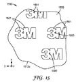
回折面フィーチャの更なる態様を、下記に更に論じる。特に注目すべき態様の1つは、少なくとも装置がオンの際、例えばユーザーが装置を直接見る場合に、装置のユーザーに印として可視の形状及び/又はパターンにある、回折面フィーチャのいくつか上に提供されるパターン化印刷(図1に示されないが、下記の他の図に示される)である。 Further aspects of diffractive surface features are discussed further below. One particularly noteworthy aspect is that on some of the diffractive surface features that are in a shape and / or pattern that is visible as a mark to the user of the device, at least when the device is on, for example when the user looks directly at the device. Pattern printing (not shown in FIG. 1 but shown in other figures below).
いくつかの場合、回折面フィーチャの少なくともいくつかは、場合により、平面図にて非直線状であってもよく、道光体内を伝搬する光は、回折面フィーチャと相互作用して、非直線状の回折面フィーチャと交差する少なくとも1つのバンドを生成してもよい。バンドは、明るいバンド、又は、いくつかの場合、暗いバンドであってもよい。バンドの外観(例えば、形状)は、照明装置110に対する観察者120の視認位置の関数として変化する。非直線状の回折フィーチャは、例えば、湾曲若しくは分割された形状を有してもよく、又は、曲線及び/若しくはセグメントを含む起伏のある若しくはばらばらの形状を有してもよい。しかしながら、いくつかの場合、道光体の主表面の一方又は両方上の回折面フィーチャのいくつか又は全部は、平面図にて直線状であり得る。個別の光源及び/又は個別の吸収材を使用した場合、直線状の回折面フィーチャによっても明るい及び/又は暗いバンドが生成し得るが、それらのバンドの形状は、視認位置の関数として曲率を変化させ得ない。
In some cases, at least some of the diffractive surface features may optionally be non-linear in plan view, and the light propagating through the path light will interact with the diffractive surface features and be non-linear At least one band that intersects the diffractive surface feature may be generated. The band may be a bright band or in some cases a dark band. The appearance (eg, shape) of the band changes as a function of the viewing position of the
照明装置110、及び本明細書に開示した他の照明装置は、一般照明目的のための照明器具、又はそれと同様の照明装置などとして使用することができる。照明器具は、任意の所望の位置及び配向で装着されてもよく、例えば部屋の天井上、若しくは天井内、若しくは天井付近、又は部屋の壁上、若しくは壁内、若しくは壁付近、又は柱、スタンド若しくは他の支持構造上に装着されてもよい。照明器具は、天井に平行に、又は壁に平行に、又は天井若しくは壁に関連して斜め若しくは中間の角度に配向されてもよい。
The
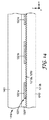
図2に、道光体内に光を入射する個別の光源214などの光源と、案内モード光216を道光体の外部に連結して、外部連結光217a、217bを提供する回折面フィーチャ213とを有する道光体212の概略図が示されている。上述した道光体112と同一又は同様であり得る道光体212は、上部に回折面フィーチャ213が設けられた第1の主表面212aと、第1の反対側の第2の主表面212bと、そこを通して光源214からの光が道光体に進入し得る側部表面212cとを有する。光源214は、電気を可視光に変換する、1つ以上のLEDダイなどの能動要素214aと、要素214aから違う方向に指向される光のいくつかを道光体212の側部表面212c内に指向させることを助ける1つ以上の反射部材214bとを含んでもよい。光源214からの案内モード光216は、全反射(TIR)を介して道光体212に沿って及び道光体212内を角度αの範囲に亘って伝搬し、該角度は、道光体の局部面、この場合はx−y面に対して測定され得る。外部連結光217a、217bは、少なくとも部分的に、所定の光線217cの伝搬方向と、道光体の局部面に垂直な軸217d、この場合はz軸との間の極角θにより測定又は特徴付けられてもよい。図2はまた、主表面212b上に衝突し、該表面212bを通して道光体212に進入し、非案内モード光として道光体212を通して伝搬し、透過光線218bとして主表面212aを通して道光体を退出する入射光線218aも示す。透過光線218bは、歪みが低い状態で道光体212を通して視認できるように、回折面フィーチャ213によって最小限に偏位されることが好ましい。
FIG. 2 includes a light source, such as a separate
本発明者らは、ここで、上述した機能的特性を提供することができる回折面フィーチャ213の関連設計特性に関して詳しく述べる。一般に、回折面フィーチャ213は、平面図にて所定の通路を追従する、高度に画定された面を有する溝又は畝/プリズムである。図2の目的のために、本発明者らは、単純化のために、回折フィーチャ213が互いに及びy軸に平行な、直線状の線状通路を追従すると仮定する。この仮定は、直線状の線状フィーチャが、平面図にて、例えば同心円又は渦巻線の弦などの湾曲した通路を追従する、回折面フィーチャの非常に小さい部分又は区分を近似し得るため、見掛けほど限定的ではない。本発明者らはまた、単純化のために、回折フィーチャ213が図2で「p」とラベルされる「ピッチ」として既知の、均一の中心間距離を有すると仮定する。この仮定も、均一に離間された回折フィーチャ213が、そのピッチpが位置の関数として変化する回折面フィーチャの非常に小さい部分又は区分を近似し得るため、見掛けほど限定的ではない。回折面フィーチャ213はまた、図2に示すように、深さ(溝)又は高さ(プリズム)「h」を有すると仮定する。 We now elaborate on the related design characteristics of the diffractive surface feature 213 that can provide the functional characteristics described above. In general, the diffractive surface feature 213 is a groove or ridge / prism with a highly defined surface that follows a predetermined path in plan view. For the purposes of FIG. 2, we assume for the sake of simplicity that the diffractive features 213 follow straight linear paths parallel to each other and to the y-axis. This assumption is apparent because a straight linear feature can approximate a very small portion or section of a diffractive surface feature that follows a curved path, such as a concentric circle or a spiral chord, in plan view. Not as restrictive. We also assume, for simplicity, that the diffractive features 213 have a uniform center-to-center distance known as the “pitch” labeled “p” in FIG. This assumption is also not as limited as it appears because uniformly spaced diffractive features 213 can approximate very small portions or sections of diffractive surface features whose pitch p varies as a function of position. The diffractive surface feature 213 is also assumed to have a depth (groove) or height (prism) “h”, as shown in FIG.
仮定された線状構成及び一定ピッチを有する回折面フィーチャ213は、単一ピッチ(又は周期的)1次元(1D)回折格子と称され得る単一ピッチ1D格子は、道光体212に直接連結され、かつ道光体212の主表面212aを形成し、本発明者らは、道光体212が屈折率nを有し、かつ空気又は真空中に浸漬されていると仮定する。光源214から光学波長λの光が側部表面212cを通して道光体212内に入射又は放たれ、案内モード光216として、主にTIRにより道光体内を、及び道光体に沿って伝搬する。そのような光が回折面フィーチャ213上に衝突し、及び回折面フィーチャ213と相互作用した際、案内モード光216の一部(η)が外部に連結された光217a、217bとして抽出される。外部連結光又は抽出光217a、217bは、以下の条件を満たす場合、道光体表面に直交する方向(例えば、図2にて極角θ=0を有する)に沿って伝搬する。
m×(λ/n)=d×cos(α)。 (1)
この等式において:αは、実質的に図2に示す表面の面に対して測定して、案内モード光が格子表面上に衝突する角度を指し;mは、回折次数であり;nは、道光体212の屈折率であり;λは、光の波長であり;dは、図2で「p」とラベルされる格子ピッチである。例えば、軸(α=0度)上で、屈折率n=1.5を有するアクリル道光体内に放たれた、λ=530nmを有する緑色光の場合、格子ピッチd(又はp)は、353nmに等しい必要があり、第1の回折次数(m=1)のみ可能である。α及びλの他の値の場合、抽出方向は、一般にもはや道光体表面に直交しないであろう。
A diffractive surface feature 213 having an assumed linear configuration and a constant pitch may be referred to as a single pitch (or periodic) one-dimensional (1D) diffraction grating. A single pitch 1D grating is directly coupled to the path light 212. And forming the main surface 212a of the path light 212, we assume that the path light 212 has a refractive index n and is immersed in air or vacuum. Light having an optical wavelength λ is incident or emitted from the
m × (λ / n) = d × cos (α). (1)
In this equation: α refers to the angle at which guided mode light impinges on the grating surface, measured substantially with respect to the plane of the surface shown in FIG. 2; m is the diffraction order; n is Λ is the wavelength of light; d is the grating pitch labeled “p” in FIG. For example, in the case of green light having λ = 530 nm emitted into an acrylic light guide having a refractive index n = 1.5 on the axis (α = 0 degree), the grating pitch d (or p) is 353 nm. Only the first diffraction order (m = 1) is possible. For other values of α and λ, the extraction direction will generally no longer be orthogonal to the road surface.
ここでコンピュータシミュレーションを使用して、単一ピッチ1D回折格子に関して、抽出光又は外部連結光の角度分布特性を光源波長の関数として解説することができる。角度分布を完全に特徴付けるために、極角(図2の角度θ)及び方位角(x−y面内で測定された、x−y面内の固定方向又は軸に対する角度)の両方を考慮する必要がある。シミュレーションを目的として、単純さのために、本発明者らは:光源214及び道光体212(回折面フィーチャ213を含む)がy軸に平行な軸に沿って無限に延び;ピッチd(又はp)が353nmであり;光源214がx−z面内にLambertian分布を有し、即ち、側部表面212cに衝突する前の、光源214により空気中に発光された光に関する強度が、αのコサインに比例すると仮定する。これらの仮定を用いてシミュレーションを行った後、本発明者らは、3つの異なる光学波長λに関して、統合された光パワー密度の全体を極角θの関数として計算し、結果を図3にプロットした。この図において、曲線310、312、314は、それぞれ450nm(青色光)、530nm(緑色光)、及び620nm(赤色光)の光学波長λに関する統合された光パワー密度を示す。
Here, computer simulation can be used to describe the angular distribution characteristics of the extracted or externally coupled light as a function of the light source wavelength for a single pitch 1D diffraction grating. To fully characterize the angular distribution, both polar angle (angle θ in FIG. 2) and azimuthal angle (measured in xy plane, fixed direction in xy plane or angle relative to axis) are considered. There is a need. For the sake of simulation, for simplicity, we have: a
図3のシミュレートされた結果は、中でも、回折面フィーチャを使用した光抽出の波長依存性の性質を示している。曲線310、312、314は幾分重なり合うが、それらのピーク強度は、互いに10度を超えて異なる極角にて生じており、赤色及び青色ピークはほぼ30度、分離している。
The simulated results of FIG. 3 show, among other things, the wavelength dependent nature of light extraction using diffractive surface features. Although
シミュレーションに加えて、本発明者らはまた単一ピッチ1D回折格子を製作して、道光体用の光抽出器としての有用性を示した。最初に、集束イオンビーム(FIB)を使用してダイヤモンド旋盤(DTM)用のダイヤモンドチップを成形して、45度の刃先角を有するV形状のダイヤモンドチップを形成した。次いで、このダイヤモンドチップを使用して、銅ロールの周辺部の周りに対称的な等間隔のV形状の溝を切削して、回折格子マスターツールを作製した。次いで、鋳込−硬化複製プロセスを用いて、格子パターンをマスターツールからフィルム基材へ転写した。3mils(約76マイクロメートル)の厚さを有するトリアセテートセルロース(TAC)フィルムを、典型的な道光体材料の屈折率によく一致するその低い複屈折及びその屈折率値(n=1.5)に起因して、基部フィルム又は基材として使用した。この基部フィルムをマスターツールに適用し、それらの間には薄いアクリレート樹脂コーティングが存在した。アクリレート樹脂組成物は、アクリレートモノマー(Cognisから入手可能な75重量% PHOTOMER 6210及びAldrich Chemical Co.から入手可能な25重量% 1,6−ヘキサンジオールジアクリレート)及び光開始剤(1重量% Darocur 1173、Ciba Specialty Chemicals)からなっていた。水銀蒸気ランプ(「D」バルブ)からの紫外線を、基部フィルム上の微細複製樹脂の鋳込及び後硬化の両方に使用した。鋳込ロールの温度は130度F(54度C)に設定し、ニップ圧は20〜25psi(約138,000〜172,000パスカル)に設定した。 In addition to simulations, the inventors have also fabricated single pitch 1D diffraction gratings that have shown utility as light extractors for road light. First, a diamond tip for a diamond lathe (DTM) was formed using a focused ion beam (FIB) to form a V-shaped diamond tip having a cutting edge angle of 45 degrees. Next, using this diamond tip, symmetrically spaced V-shaped grooves were cut around the periphery of the copper roll to produce a diffraction grating master tool. The grid pattern was then transferred from the master tool to the film substrate using a cast-cure replication process. A triacetate cellulose (TAC) film with a thickness of 3 mils (about 76 micrometers) has a low birefringence and a refractive index value (n = 1.5) that closely matches the refractive index of a typical pathogen material. Due to its use as a base film or substrate. This base film was applied to a master tool with a thin acrylate resin coating between them. The acrylate resin composition comprises an acrylate monomer (75 wt% PHOTOMER 6210 available from Cognis and 25 wt% 1,6-hexanediol diacrylate available from Aldrich Chemical Co.) and a photoinitiator (1 wt% Darocur 1173). , Ciba Specialty Chemicals). Ultraviolet light from a mercury vapor lamp (“D” bulb) was used for both casting and post-curing of the microreplicated resin on the base film. The temperature of the casting roll was set to 130 degrees F (54 degrees C), and the nip pressure was set to 20 to 25 psi (about 138,000 to 172,000 Pascals).
得られた回折格子フィルムの構造化又は溝形成表面の顕微鏡写真を図4に示す。この図にて回折面フィーチャのピッチは、約400ナノメートルであり、溝の深さ(又はプリズムの高さ)は、約500ナノメートルである。 A micrograph of the structured or grooved surface of the resulting diffraction grating film is shown in FIG. In this figure, the pitch of the diffractive surface features is about 400 nanometers, and the groove depth (or prism height) is about 500 nanometers.
次いで、このフィルムを、光学的に澄んだ粘着剤(St.Paul,Minnesotaの3M Company製の(3M(商標)Optically Clear Adhesive 8172)の層を使用して、回折格子がアクリル板の反対側に向き、かつ空気に暴露されるように、また回折格子フィルムの基部フィルムと、フィルムが接着されるアクリル板の平坦な主表面との間に有意な空隙が存在しないように、澄んだ、平坦かつ矩形の、厚さ2mmのアクリル板に積層した。このようにして積層構造は、道光体の一方の主表面上の回折面フィーチャとして機能する単一ピッチ1D回折格子を有する道光体を形成した。道光体は、図2の構成と同様の、回折面フィーチャの溝方向に平行に延びる平坦な直線状の側部表面を含んでいた。橙色発光LEDs(OSRAM Opto Semiconductors GmbHから得た)の線状アレイを使用して光源を構成し、各LEDは、約590nmの中心波長と、約20nmの半値全幅(FWHM)のバンド幅とを有する。拡散板(Baldwin,New YorkのAstra Products Inc.製のタイプDR−50)をLEDsの前方、即ちLEDsと道光体の側部表面との間に配置することにより、個々のLEDsの個別の特徴を遮蔽して、より空間的に均一の照明を提供した。かくして、光源は、波長590nmにおけるほぼ単色の光を発光する線状光源を近似した。
The film was then applied to an optically clear adhesive (St. Paul,
光源に電圧を加え、回折面フィーチャを通して発光された外部連結光の強度を、コノスコープカメラシステムを使用して、極角及び方位角の関数として測定した。測定されたコノスコープ強度分布を図5に示す。この図にて、光源の伸長方向及び溝方向は、0及び180度の方位角値に対応する。直交参照面内の、即ち図5の90及び270度の方位角値に対応する面内の測定された強度又は輝度は、図5aで極角θの関数としてプロットされている。読者は、図5aの曲線と、図3の曲線310、312、314の形状との類似性に注目し得る。読者はまた、図5を参照して、光が1D回折格子によって、面内に存在しない狭い三日月形形状の分布に抽出されるが、極角の関数として方位角内にてシフトすることにも注目し得る。
Voltage was applied to the light source and the intensity of the externally coupled light emitted through the diffractive surface feature was measured as a function of polar angle and azimuth using a conoscopic camera system. The measured conoscopic intensity distribution is shown in FIG. In this figure, the extension direction and groove direction of the light source correspond to azimuth values of 0 and 180 degrees. The measured intensity or brightness in the orthogonal reference plane, ie in the plane corresponding to the azimuth values of 90 and 270 degrees in FIG. 5, is plotted in FIG. 5a as a function of polar angle θ. The reader may note the similarity between the curve of FIG. 5a and the shape of the
図4、5及び5aに関連して論じられる拡張領域照明装置の他の態様には、以下が挙げられる。光は、道光体の両方の主表面(例えば、図2の表面212a、212b参照)から等しく抽出又は外部に連結され、これは回折面フィーチャの対称設計(即ち、線状回折格子を形成する対称V形状の溝)の結果である;単色光源が白色光源及び/又は多色光源で置き換えられた場合、回折現象の結果として角度色分離が生じるであろう(例えば図3参照);案内モード光を導波路に沿って伝搬させるのにTIRに依存し、また光を道光体から抽出又は外部に連結するのに回折に依存するという事実に起因して、装置内に拡散構成要素は必要ない(しかし、図5及び5aの実施形態では、LED光源の個別の性質を遮蔽するために光源内に1つ含まれている);並びに、外部に連結された光の三日月形形状の分布は、比較的狭い光抽出角度により特徴付けられる。 Other aspects of the extended area lighting device discussed in connection with FIGS. 4, 5 and 5a include the following. Light is equally extracted or coupled externally from both major surfaces of the path light body (see, eg, surfaces 212a, 212b in FIG. 2), which is a symmetrical design of diffractive surface features (ie, symmetrical to form a linear grating). If the monochromatic light source is replaced with a white light source and / or a multicolor light source, angular color separation will occur as a result of the diffraction phenomenon (see, eg, FIG. 3); guided mode light Due to the fact that it relies on TIR to propagate the light along the waveguide and relies on diffraction to extract light from the path light or couple it externally, no diffusion component is required in the device ( However, in the embodiment of FIGS. 5 and 5a, one is included in the light source to shield the individual properties of the LED light source); and the distribution of the crescent shape of the externally coupled light is comparable Narrow light extraction angle Characterized.
案内モード光は、回折面フィーチャの形状を変化させることにより、特に、個々のフィーチャ(例えば、プリズム)の形状を非対称に作製することにより、他方の主表面よりも道光体の一方の主表面を通して優先的に抽出又は外部に連結され得る。本発明者らは、このことを図6及び7に関連して示す。図6にて、照明装置610は、第1の主表面612aと、対向する第2の主表面612bとを有する道光体612を含む。第1の主表面612aは、小平面の形態の回折面フィーチャ613を含み、該小平面は、高さ「h」及びピッチ「p」の直角プリズム構造を形成している。装置610は、光を案内モード光として道光体内に入射する、道光体612の側部表面に近接して配置された光源614も含み、そのような光は、図6の視点から、概して左から右へ伝搬する。装置610のコンピュータシミュレーションを行った。このシミュレーションでは、単純さのために、回折面フィーチャ613のプリズム構造を、等間隔であり、y軸と平行な軸に沿って線状に延びると仮定した。光源もy軸と平行な軸に沿って線状に延びると仮定し、波長λの偏光を空気中に、道光体の面と平行な第1の参照面(図2のx−y面参照)内にLambertian分布にて発光すると仮定し、次いでこの光を道光体の側部表面にて屈折させた。シミュレーションは、第1の参照面に直交する第2の参照面(図2のx−z面参照)内で、図2を参照して唯一の光の伝搬角度、α=5度を仮定した。道光体の屈折率は、1.5と仮定した。光学波長λ及び格子ピッチpは、当初、一次回折(m=1)に関して、外部連結光が道光体表面に直交して抽出されるように選択し、これはλ≒520nm及びp≒350nmを与えた。次いで、格子の高さを、50〜500nmの範囲に亘って変更する一方、ピッチpは350nmにて一定に保った。格子の高さの特定の値に関連した各実施形態において、コンピュータシミュレーションソフトウェアにより以下の量が計算された。
・本明細書ではTM−頂部抽出効率と称する、第1の主表面612aから抽出された横方向磁気(TM)偏光に関する抽出効率、
・本明細書ではTE−頂部抽出効率と称する、第1の主表面612aから抽出された横方向電気(TE)偏光に関する抽出効率、
・本明細書ではTM−底部抽出効率と称する、第2の主表面612bから抽出された横方向磁気(TM)偏光に関する抽出効率、
・本明細書ではTE−底部抽出効率と称する、第2の主表面612bから抽出された横方向電気(TE)偏光に関する抽出効率。
Guide mode light is transmitted through one main surface of the path light body rather than the other main surface by changing the shape of the diffractive surface features, in particular by making the shape of individual features (eg prisms) asymmetric. It can be preferentially extracted or connected to the outside. We show this in connection with FIGS. 6 and 7. In FIG. 6, the
-Extraction efficiency for transverse magnetic (TM) polarization extracted from the first
Extraction efficiency for transverse electrical (TE) polarization extracted from the first
-Extraction efficiency for transverse magnetic (TM) polarization extracted from the second
-Extraction efficiency for transverse electrical (TE) polarization extracted from the second
この観点から、「抽出効率」は、単一の相互作用に関して特定の主表面(612a又は612b)から抽出された特定の光(TM又はTE)の量(百分率として表す)を、道光体内を伝搬するそのような特定の光の、その光線が抽出表面と相互作用する直前の量で除算したものを指す。 From this point of view, “extraction efficiency” refers to the amount of specific light (TM or TE) extracted from a specific major surface (612a or 612b) for a single interaction (expressed as a percentage) through the light source. Refers to the specific light that is divided by the amount just before the ray interacts with the extraction surface.
計算した量を図7にプロットし、ここで曲線710は、TM−底部抽出効率であり、曲線712は、TE−底部抽出効率であり、曲線714は、TM−頂部抽出効率であり、曲線716は、TE−頂部抽出効率である。これらの結果は、個々の回折フィーチャ(例えば、プリズム)の形状を非対称に作製することにより、案内モード光が道光体の一方の主表面を通して優先的に抽出され得ることを示す。結果はまた、光が一方の主表面から優先的に抽出される程度は、回折フィーチャの特定の形状の詳細に依存することも示す。直角プリズムフィーチャの場合、優先的な抽出は、高さhをピッチpとほぼ等しいように選択することにより最大となり得る。
The calculated quantities are plotted in FIG. 7, where
回折面フィーチャは、道光体の一方の主表面から発光された光(例えば、図2の外部連結光217a)が、道光体の対向する主表面から発光された光(例えば、図2の外部連結光217b)と同一又は同様であるように調整されてもよい。対向する表面から発光された光は、外部連結光の色及び/又は強度に関連して同一であり得る。一手法では、回折面フィーチャは、両方の対向する主表面上に提供されてもよく、これらの回折面フィーチャは、対向する主表面の間に、該主表面から等距離で配置された参照面に関連して互いに鏡像であってもよく、それにより照明装置はそのような参照面に関連して鏡像対称性を所有する。代替的実施形態では、回折面フィーチャは、道光体の一方の主表面から発光された光が、道光体の対向する主表面から発光された光と実質的に異なるように調整されてもよい。対向する表面から発光された光は、外部連結光の色及び/又は強度に関連して異なり得る。例えば、観察者は、一色の光が一方の主表面から発光され、実質的に異なる色の光が対向する主表面から発光されることを知覚し得る。水平に装着された照明装置では、白色光源は、比較的冷たい色温度(青みがかった色合い)の白色光が天井に向かって指向され、比較的暖かい色温度(赤みがかった色合い)の白色光が床に向かって指向され、又はその逆であるように、好適に調整された回折面フィーチャを有して使用されてもよい。 The diffractive surface feature is such that light emitted from one main surface of the road light (eg, externally coupled light 217a in FIG. 2) is emitted from the opposite main surface of the roadlight (eg, externally coupled in FIG. 2). It may be adjusted to be the same as or similar to light 217b). The light emitted from the opposing surfaces can be the same with respect to the color and / or intensity of the externally coupled light. In one approach, diffractive surface features may be provided on both opposing major surfaces, and these diffractive surface features are located between opposing major surfaces and equidistant from the major surface. May be mirror images of each other, so that the illuminator possesses mirror image symmetry with respect to such a reference plane. In an alternative embodiment, the diffractive surface feature may be tuned so that light emitted from one major surface of the path light body is substantially different from light emitted from the opposite major surface of the path light body. The light emitted from the opposing surfaces can be different with respect to the color and / or intensity of the externally coupled light. For example, an observer may perceive that one color of light is emitted from one major surface and a substantially different color of light is emitted from the opposite major surface. In a horizontally mounted lighting device, the white light source is directed at the ceiling with white light with a relatively cool color temperature (bluish hue) and white light with a relatively warm color temperature (reddish hue) on the floor. It may be used with a diffractive surface feature that is suitably tuned to be directed toward it or vice versa.
回折に起因した、異なる色の角度分離が望ましくない用途では、いくつかの設計手法を用いて、色分離の問題を克服することができる。図8に示す一手法では、2つ以上の道光体を互いに積層してもよい。図9に示す別の手法では、異なる回折面フィーチャを所定の道光体の反対側の主表面上に配置し、異なる色の光源用に調整する。図10及び11に示す尚別の手法では、道光体の所定の主表面上の回折面フィーチャは、異なるピッチの表面フィーチャのグループを含んでもよい。これらの手法は色分離問題に対する対処に関連して示されているが、該手法は、色分離が尚生じる実用的及び/若しくは美的目的を含む他の目的、又は所定の所望の(非白色)色の光源のみを使用する単一色の実施形態にも、使用できることに留意されたい。様々な手法は個々に記載されているが、手法の任意の2つ以上を互いに組み合わせて、単一の実施形態に使用できることにも留意されたい。 In applications where angular separation of different colors due to diffraction is undesirable, several design techniques can be used to overcome the color separation problem. In one method shown in FIG. 8, two or more light guides may be stacked on each other. In another approach shown in FIG. 9, different diffractive surface features are placed on the opposite major surface of a given path light body and adjusted for different color light sources. In yet another approach shown in FIGS. 10 and 11, the diffractive surface features on a given major surface of the path light body may include groups of surface features of different pitches. Although these approaches are shown in connection with addressing the color separation problem, they may be used for other purposes, including practical and / or aesthetic purposes where color separation still occurs, or for any desired (non-white) Note that single color embodiments using only a color light source can also be used. It should also be noted that although the various techniques are described individually, any two or more of the techniques can be combined with each other and used in a single embodiment.
図8を再び参照すると、積層され又は層状にされた配置にある複数の道光体812、832、852を含む照明装置810の概略図が示されている。各道光体は、対向する一対の主表面を有し、即ち道光体812は主表面812a、812bを有し、道光体832は主表面832a、832bを有し、道光体852は主表面852a、852bを有する。各道光体の少なくとも一方の主表面は、回折面フィーチャを含むことが好ましく、例えば、主表面812aは回折面フィーチャ813を含んでもよく、主表面832aは回折面フィーチャ833を含んでもよく、主表面852aは回折面フィーチャ853を含んでもよい。装置810はまた、図示するように配置された光源814a、814b、834a、834b、854a、854bも含んで、例えばそれらの対応する側部表面を通して、対応する道光体に光を入射することによって、案内モード光を道光体内に提供してもよい。道光体(それらの回折面フィーチャを含む)のそれぞれは、非案内モード光が比較的妨害されずに道光体を通過できるように、低い光学的歪みを有することが好ましい。この方法で、回折面フィーチャ833により道光体832から抽出された光は、道光体812を通過してユーザー820及び/又は表面822に到達することができ、回折面フィーチャ853の道光体852から抽出された光は、道光体812及び道光体832の両方を通過してユーザー820及び/又は表面822に到達することができる。更に、ユーザー820は、道光体812、832、852を通しても、光学的歪みを殆ど又は全く有さずに、上述した物体124と同一又は同様であり得る物体824などの物体を観察することができる。
Referring again to FIG. 8, there is shown a schematic diagram of a
色分離問題を克服することを所望する場合、装置810内の様々な道光体、光源、及び回折面フィーチャを調整して、それらの全色の合計が、実質的に白色の光照明を提供するように、異なる色の外部連結光をユーザー820及び/又は表面822に提供することができる。例えば、光源854a、854bは赤色光を発光してもよく、回折面フィーチャ853は装置の光学軸(例えば、z軸に平行な軸)に沿ってそのような光を最適に抽出してもよく、光源834a、834bは緑色光aを発光してもよく、回折面フィーチャ833は同一の光学軸に沿って緑色光を最適に抽出してもよく、光源814a、814bは青色光を発光してもよく、回折面フィーチャ813は同一の光学軸に沿って青色光を最適に抽出してもよい。勿論、記載された赤色、緑色及び青色の順序は単なる例であり、読者は多数の代替的組み合わせを想定することが理解されるであろう。更に、図8の積層体には3つの道光体が示されているが、2つ、4つ、又はそれ以上を含む他の数の道光体も使用し得る。積層体内の各層の成分構成要素は、同一又は同様の設計、例えば、同一の道光体寸法及び特性、同一の回折面構造の寸法及び特性、並びに同一のLEDsの数、色、及び配置を有してもよい。代替的に、各層の成分構成要素は、これらの任意の点で、他の層内の対応する構成要素とは異なっていてもよい。照明装置110と同様に、装置810は、実質的に白色の光照明を表面822上に提供する一方、ユーザー820が装置810を直接見た場合、有色の外観を提供することができる。また、ユーザーは、装置810の発光範囲内に、印などの空間的パターン(1つ又は複数)を見ることが望ましく、このパターン(1つ又は複数)又は印は、積層体内の層の任意の1つ、又はいくつか、又は全部を起源としてもよい。
If it is desired to overcome the color separation problem, the various light sources, light sources, and diffractive surface features in
図9を再び参照すると、道光体912と光源914a、914bとを含む照明装置910の概略図が示され、光源914a、914bは、道光体の異なる(例えば、直交する)側部表面内に光を入射するように配置されている。道光体912は、対向する一対の主表面912a、912bを有する。装置910において、各主表面は、それ自体の回折面フィーチャを有する。表面912aは、回折面フィーチャ913aを有し、表面912bは、回折面フィーチャ913bを有する。回折面フィーチャは、図に概略的にのみ表されているが、フィーチャ913aは、1つの面内軸(例えば、y軸)に略平行に延び、フィーチャ913bは、直交する面内軸(例えば、x軸)に略平行に延びることを示す。光源は、同様に、概ね直交面内方向に沿って光を入射するように配置及び構成され、光源914aは、概ねx軸に沿って光を入射するように配置され、光源914bは、概ねy軸に沿って光を入射するように配置されている。用語「概ね」は、光源はコリメートされる必要はない(そして多くの場合、コリメートされない)が、x−y面に角度分布させて光を発光するため、本明細書にて使用される。また、光源914a、914bはそれぞれ、単一LEDエミッタなどの個別の点光源として示されているが、これらは代替的に、それぞれ、道光体の対応する側部表面に沿って延びる光源の線状アレイ、又は線状若しくはバー形状の拡張光源であってもよい。にも係わらず、光源914aからの光は、該光が回折面フィーチャ913aと強く相互作用し、かつ回折面フィーチャ913bと弱く相互作用するように面内x軸に沿って優位に伝搬し、光源914bpからの光は、該光がフィーチャ913aと強く相互作用し、かつフィーチャ913bと弱く相互作用するように面内y軸沿って優位に伝搬する。
Referring again to FIG. 9, there is shown a schematic diagram of a
この配置又は方向性を用いた道光体上の異なるそれぞれの回折面フィーチャに対する光源の選択的連結は、所望であれば、色分離の問題に対処するのに使用することができる。例えば、光源はそれらの発光スペクトルが実質的に相補的であってもよく、例えば、光源914aは青色光を発光してもよく、かつ光源914bは黄色光を発光してもよく、その場合、回折面フィーチャ913aは、照明装置910の光学軸(例えば、正z軸)などの所定の方向に沿って青色光を抽出するように構成され得る一方、回折面フィーチャ913bは、同一の方向に沿って黄色光を抽出するように構成され得ることにより、実質的に白色の光照明を光学軸に沿って提供することができる。青色光又は黄色光と、反対の色の回折面フィーチャ(光抽出格子)との相互作用は殆どなく、これは、上記に説明したように、青色光抽出用の溝は概ね黄色光の光路に沿って延び、黄色光抽出の溝は概ね青色光の光路に沿って延びるためである。それ故、異なる色の光線は、同一の道光体内で独立して案内及び抽出される。外部に連結された青色及び黄色光の組み合わされた視覚効果は、観察者又はユーザーに白色光の感覚を生じる。しかしながら、この例での白色光の演色評価数(CRI)は、道光体912が2色のみを組み合わせるため、比較的低い。
Selective coupling of light sources to different respective diffractive surface features on the path light using this arrangement or orientation can be used to address the problem of color separation, if desired. For example, the light sources may be substantially complementary in their emission spectra, for example, the
図9に示す手法は、異なる相補的な色、及び相補的ではない色の組み合わせを含む、また同一であり得る色(例えば、両方の光源914a及び914bに関して緑色発光光、又は両方の光源に関して赤色発光光)を含む、他の色の光源を使用する実施形態を含む、多数の他の実施形態に拡大適用することができる。また、装置910のような照明装置は、同様の又は異なる設計の他の照明装置と、例えば図8に関連して記載したような積層配置にて組み合わされてもよい。そのような場合、各道光体は、所望であれば、2つの区別される色の組み合わせを発光し、積層体から集合的に発光された色がより高いCRIを有する白色光を生成するように選択されてもよい。
The approach shown in FIG. 9 includes different complementary colors and non-complementary color combinations and may be the same color (eg, green emission light for both
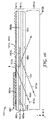
色分離の問題に対処するのに使用できる他の手法は、概して図10及び11に示す手法である。これらの図では、所定の主表面上の回折面フィーチャが異なるピッチの表面フィーチャのグループ又はパケットを含む道光体1012、1112が示されている。多数の異なるピッチを使用して、様々な波長の、道光体からの抽出光の所望の分布を提供することができ、それらの波長の光は、1つ以上の光源(図示せず)により道光体内に入射されることを仮定する。
Another approach that can be used to address the color separation problem is the approach generally shown in FIGS. In these figures, a path
本明細書の他の箇所で述べたように、本明細書に開示した道光体は、一体構造、又は、2つ以上の構成要素が、介在する有意な空隙を有することなく互いに取り付けられている、層状にされた構造を含む、多様な異なる構造を有することができる。この観点から、道光体1012、1112は層状にされた構造を有するように示されるが、所望であれば、一体構造を有するように容易に変更することができる。反対に、他の図で道光体は一体型として示されるが、層状にされた構造を有するように容易に変更することができる。図10を参照すると、道光体1012は比較的厚い板又は他の基材1011aを含み、該板又は他の基材1011aに、上部にプリズム層1011cが鋳込み及び硬化されているキャリアフィルム1011bから作製されたフィルムが取り付けられている。基材1011a、キャリアフィルム1011b、及びプリズム層1011cは、同一又は同様の屈折率を有することが好ましく、全て散乱又は吸収が殆ど又は全くなく、可視光に対して高い透過性を有することが好ましいが、いくつかの場合、制御量の吸収及び/又は散乱が許容可能であり、又は更には所望され得る。図11を参照すると、道光体1112は道光体1012に類似した構造を有してもよく、したがって比較的厚い板又は他の基材1111aを含んでもよく、該板又は他の基材1111aに、上部にプリズム層1111cが鋳込み及び硬化されているキャリアフィルムが取り付けられている。
As described elsewhere herein, the light guide disclosed herein is a unitary structure, or two or more components are attached to each other without significant intervening voids. It can have a variety of different structures, including layered structures. From this point of view, the light guides 1012, 1112 are shown as having a layered structure, but can be easily modified to have an integral structure if desired. Conversely, in other figures, the light guide is shown as a single piece, but can be easily modified to have a layered structure. Referring to FIG. 10, a
板又は他の基材に対してプリズム又は構造化表面フィルムを取り付けて層状にされた道光体を提供することは、任意の好適な技術により行うことができる。例えば、取り付けは、光透過性感圧接着剤などの好適な接着剤を使用して達成することができる。取り付けはまた、インサート射出成形プロセスを含む射出成形プロセスを用いて達成されてもよい。例えば硬化性樹脂がキャリアフィルムなどの好適な基材上に鋳込み及び硬化される場合、化学結合も取り付けに用いることができる。代替的に、一体構造の場合、回折面フィーチャは、型押し、又は、例えば射出成形プロセスを含む成形により、フィルム又は板などの一体基材の少なくとも1つの表面上に形成することができる。圧縮成形、押出複製、及び直接切削は、回折面フィーチャを形成するのに使用できる追加の技術である。フィルム、板、又は他の基材の表面上に如何なる回折構造が形成されるかに係わらず、回折面フィーチャは、既知の技術又は後に開発される任意の好適な技術を用いて加工することができる。好適な回折面フィーチャを作製するのに用いられ得る更なる方法は:国際公開第2011/088161号(Wolk et al.);米国特許第2012/0098421号(Thompson);及び同第2012/0099323号(Thompson)の1つ以上に論じられている。 Providing a layered path light by attaching a prism or structured surface film to a plate or other substrate can be done by any suitable technique. For example, attachment can be accomplished using a suitable adhesive, such as a light transmissive pressure sensitive adhesive. Attachment may also be accomplished using an injection molding process including an insert injection molding process. For example, when the curable resin is cast and cured on a suitable substrate such as a carrier film, chemical bonds can also be used for attachment. Alternatively, in the case of a monolithic structure, the diffractive surface features can be formed on at least one surface of a monolithic substrate, such as a film or plate, by embossing or molding including, for example, an injection molding process. Compression molding, extrusion replication, and direct cutting are additional techniques that can be used to form diffractive surface features. Regardless of what diffractive structures are formed on the surface of a film, plate, or other substrate, diffractive surface features can be processed using known techniques or any suitable technique developed later. it can. Further methods that can be used to make suitable diffractive surface features are: WO 2011/0888161 (Walk et al.); US 2012/0098421 (Thompson); and 2012/0099323. (Thompson).
道光体1012、1112は、それぞれの第1の主表面1012a、1112aと、第1の表面の反対側のそれぞれの第2の主表面1012b、1112bと、側部表面(図示せず)とを有する。本明細書に記載した他の道光体と同様、第1の主表面1012a、1112aは、それぞれ回折面フィーチャ1013、1113を有するように構成されている。表面フィーチャは、溝又はプリズムと称されてもよい。溝/プリズムは、非対称の90度鋸歯プロファイルを断面に有するよう示されているが、所望により他の非対称プロファイル及び対称(例えば、V−形状)プロファイルを含む他のプロファイルも使用し得る。平面図にて溝/プリズムは、直線状の、湾曲した、又は両方(例えば、ある場所では直線状であり、他の場所では湾曲した)の通路を追従してもよい。意義深いことには、回折面フィーチャ1013、1113はグループ又はパケットに配置され、任意の所定のパケット内のプリズム又は溝は、均一のピッチを有するが、隣接するパケットは異なるピッチを有する。いくつかの場合、パケットは、道光体表面の全域で反復するパターンに配置されてもよく、パケットの最小の反復グループは、本明細書でパケットの「セット」と称する。例えば、道光体1012(図10)は、溝又はプリズムパケット1030、1031及び1032に分割される回折面フィーチャ1013を有し、これらのパケットは、セット1040を画定する反復の連続にて配置されている。パケット1030、1031、1032のそれぞれ内のプリズム又は溝は、均一のピッチを有するが、パケット1030内のピッチはパケット1031内のピッチよりも小さく、次にパケット1031内のピッチは、パケット1032内のピッチよりも小さい。道光体1112(図11)は、溝又はプリズムパケット1130、1131、1132、1133、1134、及び1135に分割される回折面フィーチャ1113を有する。これらのパケットも、反復の連続にて配置されてセット1140を画定してもよい。パケット1130、1131、1132、1133、1134、及び1135のそれぞれ内のプリズム又は溝は、均一のピッチを有するが、ピッチはパケット1130からパケット1135へ移動するにつれて、漸進的に大きくなる。異なるピッチが図10及び11に示す様々なパケットに使用されているが、好ましくはピッチのいずれも、いくつかの可視案内モード光を回折の原理によって道光体の外部に連結するのに好適な範囲内にあることに留意されたい。
The light guides 1012, 1112 have respective first
パケットの幅(面内横方向寸法)及びパケットのセットの幅は、道光体が平面図で見る場合に普段の観察者には視覚的に知覚不可能であるのに十分小さい場合がある。代替的に、パケットの幅及び/又はパケットのセットの幅は、普段の観察者に印又は美的パターンとして知覚可能であるように十分大きくてもよい。パケットが知覚可能な印を形成するように設計された場合、それらのピッチ関連の印は、いくつかの場合、回折面フィーチャ上のパターン化印刷により形成された印と位置合わせされるように作製されてもよいが、他の場合、ピッチ関連の印は、パターン化印刷により形成された印と位置合わせされなくてもよく、例えば、ピッチ関連の印は、パターン化印刷印と部分的に重なり合ってもよく、又はピッチ関連の印とパターン化印刷印との間に重なり合いが存在しなくてもよい。 The width of the packet (in-plane lateral dimensions) and the width of the set of packets may be small enough that the path light body is visually invisible to a normal observer when viewed in plan view. Alternatively, the width of the packet and / or the width of the set of packets may be large enough to be perceivable as a mark or aesthetic pattern by a normal observer. When packets are designed to form perceptible marks, their pitch-related marks are in some cases made to align with marks formed by patterned printing on diffractive surface features In other cases, pitch-related marks may not be aligned with marks formed by patterned printing, for example, pitch-related marks may partially overlap with patterned printing marks. Or there may be no overlap between the pitch-related mark and the patterned print mark.
図10及び11に示すような多数のピッチ抽出設計を、色混合に使用することができる。一般的には、2つの異なるピッチにより特徴付けられる少なくとも2つの異なるパケットを使用してもよいが、多くの場合、3つの異なるピッチp1、p2、p3により特徴付けられる少なくとも3つの異なるパケットが望ましい。ピッチ寸法の選択は、道光体の屈折率(n)の関数であり、また、本発明者らが所定のパケットによって道光体から抽出することを願う光(λ)の波長の関数でもある。例示的な場合では、本発明者らはp1=λ1/nを選択し得、λ1は400〜600nmの範囲内であり、p2=λ2/nを選択し得、λ2は500〜700nmの範囲内であり、p3=λ3/nを選択し得、λ3は600〜900nmの範囲内である。アクリル(n≒1.49)又は類似した材料で作製された道光体の場合、これらの条件は、約268〜403nmのピッチp1、約336〜370nmのピッチp2、及び403〜604nmのピッチp3の範囲内に対応する。道光体内を伝搬する白色光などの多色性光は、多数のピッチパケットと相互作用し、したがって異なる色の光は、各所定のパケットに関して異なる角度で回折され(導波路から外部に連結され又は抽出され)、任意の所定の色の抽出角度も、異なるパケットに関して異なる。その結果、様々な色の光が混合及び組み合わされて、実質的な色均一性、例えば実質的に白色の光を有する照明を、道光体から好適な距離に配置されたユーザー又は物体に対して提供することができる。 A number of pitch extraction designs as shown in FIGS. 10 and 11 can be used for color mixing. In general, at least two different packets characterized by two different pitches may be used, but in many cases at least three different packets characterized by three different pitches p1, p2, p3 are desirable . The selection of the pitch dimension is a function of the refractive index (n) of the road light, and is also a function of the wavelength of light (λ) that we wish to extract from the road light by a predetermined packet. In an exemplary case, we can select p1 = λ1 / n, where λ1 is in the range of 400-600 nm, p2 = λ2 / n, and λ2 is in the range of 500-700 nm. And p3 = λ3 / n can be selected, where λ3 is in the range of 600-900 nm. For a light guide made of acrylic (n≈1.49) or similar material, these conditions are about a pitch p1 of about 268-403 nm, a pitch p2 of about 336-370 nm, and a pitch p3 of 403-604 nm. Corresponds within the range. Polychromatic light, such as white light propagating in the light guide, interacts with a large number of pitch packets, so different colored light is diffracted at different angles for each given packet (coupled out of the waveguide or externally The extraction angle of any given color is also different for different packets. As a result, various colors of light are mixed and combined to provide substantial color uniformity, for example illumination with substantially white light, to a user or object located at a suitable distance from the road light. Can be provided.
例示的な実施形態では、照明装置は、異なるスペクトル出力を有する複数の光源を使用してもよく、制御装置を使用して異なる光源を独立して制御して、照明装置により発光される光の色の知覚色を能動的又は動的に制御してもよい。この能動的制御を用いて、出力光の色温度、相関色温度、及び/又は演色評価数(CRI)を調整又は別様に変化させてもよい。赤色、緑色及び青色発光LEDs(RGB)、又は赤色、緑色、青色及び白色発光LEDs(RGBW)のアセンブリ又は組み合わせは、この目的に特に有益である。また、多数のピッチ抽出設計を組み込んだ道光体も、特に有益である。好ましくは、多数のピッチ設計は、各狭帯域発光光源のための所定のピッチの、回折フィーチャの少なくとも1つのパケット、例えば、そのピッチが赤色光用に調整された1つ以上のパケット、そのピッチが緑色光用に調整された1つ以上のパケット、そのピッチが青色光用に調整された1つ以上のパケット、などを組み込んでいる。個々の狭帯域色は赤色、緑色及び青色に限定されず、黄色又はコハク色などの他の非白色を発光する光源も、開示した照明装置の色域を拡大するよう使用できることに留意されたい。 In an exemplary embodiment, the lighting device may use a plurality of light sources having different spectral outputs, and the control device is used to control the different light sources independently, so that The perceived color may be actively or dynamically controlled. This active control may be used to adjust or otherwise change the color temperature, correlated color temperature, and / or color rendering index (CRI) of the output light. The assembly or combination of red, green and blue light emitting LEDs (RGB) or red, green, blue and white light emitting LEDs (RGBW) is particularly beneficial for this purpose. Also, a light guide that incorporates multiple pitch extraction designs is particularly beneficial. Preferably, the multiple pitch design provides at least one packet of diffractive features of a predetermined pitch for each narrowband light source, eg, one or more packets whose pitch is adjusted for red light, the pitch Includes one or more packets tuned for green light, one or more packets whose pitch is tuned for blue light, and the like. Note that the individual narrowband colors are not limited to red, green and blue, and other non-white light sources such as yellow or amber can also be used to expand the color gamut of the disclosed lighting device.
多ピッチ格子設計、及び他の開示された回折面フィーチャ設計のための関心設計パラメータは、有効抽出効率である。抽出効率は上述してあり、ここでは繰り返さない。「有効」抽出効率とは、単一の相互作用に関して特定の主表面(612a又は612b)から抽出された特定の光を、道光体内を伝搬するそのような特定の光の、その光が抽出表面と相互作用する直前の量で除算した百分率を指す。所定のピッチの回折面フィーチャ(溝又はプリズム)に関する有効抽出効率を評価し、他のピッチの有効抽出効率と比較してもよい。所定のシステムパラメータに一般的であるように、所定のピッチの有効抽出効率:は、そのピッチを有する回折フィーチャの平面図範囲の適用範囲(例えば、図10の最小ピッチに関しては、表面上の3つのパケット1030の平面図範囲の合計)の線形関数(即ち、該範囲に直接比例する)であり;回折フィーチャのピッチ及び回折フィーチャの断面プロファイル形状(溝/プリズム)を含む他の因子にも依存する。実質的な色均一性を得るためには、異なるピッチに関する有効抽出効率が互いに同等であることを確実にすることが望ましく、例えば、区別される任意の2つのピッチに関する有効抽出効率の比が、約0.3〜3の範囲内に存在することが好ましい。
A design parameter of interest for multi-pitch grating design, and other disclosed diffractive surface feature designs, is effective extraction efficiency. The extraction efficiency has been described above and will not be repeated here. “Effective” extraction efficiency refers to the specific light extracted from a specific major surface (612a or 612b) for a single interaction, such specific light propagating through the light source, where the light is the extraction surface Percentage divided by the amount immediately before interacting with. The effective extraction efficiency for a given pitch diffractive surface feature (groove or prism) may be evaluated and compared to the effective extraction efficiency of other pitches. As is typical for a given system parameter, the effective extraction efficiency of a given pitch is the coverage of the plan view range of a diffractive feature having that pitch (eg, 3 on the surface for the minimum pitch in FIG. 10). Is a linear function (ie, directly proportional to the range) of one
図4、5、及び5aに関連して示したように、単一ピッチ線状回折格子を有する道光体内に光を入射するのに使用される単色のLambertian光源は、比較的狭い光抽出角度により特徴付けられる外部に連結された光の三日月形形状の分布を生じる。外部に連結された光の角度を更にもっと狭くすることを所望する場合、Lambertianではなく、好適なレンズ、鏡、又は他の構成要素を用いて光源を再構成して、コリメートされ又はほぼコリメートされた光を発光してもよい。反対に、外部に連結された光の角度をより広くすることを所望する場合、Lambertian分布よりも広い角度範囲に亘って光を発光するように光源を再構成してもよい。微細構造化光学フィルムをLEDs又はレーザーなどの光源と組み合わせて、道光体内に入射される光の角拡散を調整することにより、外部に連結された光の角拡散にも影響を与えることができる。好適な微細構造化光学フィルムは、PCT国際特許公開第2012/075352号(Thompson et al.)及び同第2012/075384号(Thompson et al.)に記載されている。均一性テープと称され得るこれらの光学フィルムは、道光体の縁又は側部表面に直接適用され、光源に向かって外側に向いた屈折構造を含んで、道光体内への光の連結を向上させる。屈折構造は、代替的に、例えば射出成形、型押し、又は直接機械加工によって、側部表面又は道光体の入射縁内に直接組み込まれてもよい。そのような光学フィルム又は屈折構造は、LED光源と道光体の側部表面との間に配置された際、道光体内に入射される光の角拡散をより広くし得、本明細書に開示した任意の実施形態における光源の1つ、いくつか、又は全部と共に使用することができる。カスタム設計された複製構造を有する光学フィルムはまた、コヒーレントレーザーと共に使用されて、道光体内への入射のための光の高度に画定された矩形形状の角度分布(即ち、角度の特定の円錐に亘ってほぼ一定の強度、及び、特定の円錐の外部にて0若しくはほぼ0の強度の光分布)を提供することができる。 As shown in connection with FIGS. 4, 5 and 5a, a monochromatic Lambertian light source used to enter light into a light guide having a single pitch linear diffraction grating has a relatively narrow light extraction angle. This produces a crescent-shaped distribution of externally coupled light that is characterized. If it is desired to further reduce the angle of the externally coupled light, the light source is reconfigured using a suitable lens, mirror, or other component, rather than Lambertian, to be collimated or nearly collimated. May emit light. Conversely, if it is desired to make the angle of light coupled to the outside wider, the light source may be reconfigured to emit light over a wider angular range than the Lambertian distribution. By combining the microstructured optical film with light sources such as LEDs or lasers to adjust the angular diffusion of light incident on the light path body, the angular diffusion of light coupled to the outside can also be influenced. Suitable microstructured optical films are described in PCT International Patent Publication Nos. 2012/0775352 (Thompson et al.) And 2012/075384 (Thompson et al.). These optical films, which can be referred to as uniformity tapes, are applied directly to the edge or side surface of the path light body and include a refractive structure directed outward toward the light source to improve the coupling of light into the path light body. . The refractive structure may alternatively be integrated directly into the side surface or the entrance edge of the pathlight, for example by injection molding, stamping or direct machining. Such an optical film or refractive structure can provide a wider angular spread of light incident on the light path when disposed between the LED light source and the side surface of the light path, as disclosed herein. It can be used with one, some, or all of the light sources in any embodiment. Optical films with custom designed replication structures can also be used with coherent lasers to provide a highly defined rectangular angular distribution of light (ie, over a specific cone of angles) for incidence into the path light. A substantially constant intensity and a light distribution of 0 or approximately 0 intensity outside a particular cone).
外部連結光の角拡散はまた、回折フィーチャのパケットの物理的な幅(面内横方向寸法)を適切に選択することにより調整することができ、この物理的幅は、プリズム/溝の伸長方向に直交して測定される。各パケットの物理的幅は、パケットと相互作用する光の全色に影響を与え、全体的な抽出光は、全パケットの平均効果である。小さい物理的幅は、外部連結光の角度幅を広くする傾向がある一方、大きい物理的幅は、外部連結光の角度幅を狭くする傾向がある。しかしながら、物理的幅の調整により達成できる角度を広く又は狭くする量は幾分限定されており、これは、小さすぎる物理的幅は、回折面フィーチャが「高い程度の」歪み又は散乱を生成するように、また道光体が回折的ではなく拡散的になると思われるように、過剰な光拡散をもたらし得るためである。 The angular spread of the externally coupled light can also be adjusted by appropriate selection of the physical width (in-plane lateral dimension) of the diffractive feature packet, this physical width being the extension direction of the prism / groove Is measured orthogonal to The physical width of each packet affects the total color of light that interacts with the packet, and the overall extracted light is the average effect of all packets. A small physical width tends to widen the angular width of the externally coupled light, while a large physical width tends to narrow the angular width of the externally coupled light. However, the amount of widening or narrowing of the angle that can be achieved by adjusting the physical width is somewhat limited, which is that a physical width that is too small will cause the diffractive surface features to produce a “high degree” of distortion or scattering. And because it can lead to excessive light diffusion so that the path light body appears to be diffuse rather than diffractive.
より角度分散された(遠隔の表面における、より良好な空間的均一性のために)照明を生成するための他の技術は、例えば図5のコノスコーププロットにおける異なる方位角に対応する異なる面内方向に沿って配向された、回折面フィーチャのパターンを使用することである。また、異なるように配向された回折フィーチャを、対応する回折フィーチャによる最大抽出効率のために調整された異なる面内方向に概ね沿って光を発光する、対応する光源と組み合わせることが好ましい。様々に配向された回折フィーチャと様々に配向された光源との組み合わせを提供して、多様な方位角方向に発光された外部連結光を生成し、より角度分散され及びより空間的に均一の照明をもたらすことができる。例示的な実施形態では、120度の方位角で互いに分離された面内軸に対応する、少なくとも3つの区別される回折フィーチャ配向を使用することができる。 Other techniques for generating illumination that is more angularly dispersed (for better spatial uniformity at remote surfaces) are, for example, different in-planes corresponding to different azimuth angles in the conoscopic plot of FIG. Use a pattern of diffractive surface features oriented along the direction. Also, differently oriented diffractive features are preferably combined with corresponding light sources that emit light generally along different in-plane directions adjusted for maximum extraction efficiency by the corresponding diffractive features. Provide a combination of differently oriented diffractive features and differently oriented light sources to produce externally coupled light emitted in various azimuthal directions, more angularly dispersed and more spatially uniform illumination Can bring. In an exemplary embodiment, at least three distinct diffractive feature orientations can be used that correspond to in-plane axes separated from one another by an azimuth angle of 120 degrees.
異なるように配向された回折フィーチャはまた、連続的に湾曲した溝又はプリズム、例えば、円形、楕円形若しくは長円形の(平面図にて)の溝又はプリズム、又はそのような形状の部分、例えば、正弦曲線若しくは別様に起伏のある形状などの相互接続された一連の弧を含む弧の使用を介して達成されてもよい。その観点から、線状回折面フィーチャを有するとして記載された、本明細書に開示した実施形態は、代替的に、湾曲した回折フィーチャを使用してもよい。線状又は湾曲した回折面フィーチャは、個別の光源及び/又は非均一の反射性構造と組み合わされた際、明るい又は暗いバンドの形態の視覚的フィーチャを生成するのに使用することができる。このようなバンドは、殆どの拡張光源用途には全く望ましくないが、いくつかの場合、上述したパターン化印刷により提供されるパターン(1つ又は複数)又は印の外観を向上させ得る、美的3次元外観を有する照明装置を提供するのに活用することができる。そのようなパターン化印刷を、図12から開始して以下に更に論じる。 Differently oriented diffractive features can also be continuously curved grooves or prisms, such as circular, elliptical or oval (in plan view) grooves or prisms, or parts of such shapes, such as May be achieved through the use of arcs comprising a series of interconnected arcs, such as sinusoids or otherwise undulating shapes. In that regard, the embodiments disclosed herein described as having linear diffractive surface features may alternatively use curved diffractive features. Linear or curved diffractive surface features can be used to generate visual features in the form of bright or dark bands when combined with individual light sources and / or non-uniform reflective structures. Such a band is completely undesirable for most extended light source applications, but in some cases it can enhance the appearance of the pattern (s) or indicia provided by the patterned printing described above. It can be utilized to provide a lighting device having a dimensional appearance. Such patterned printing is further discussed below, starting with FIG.
図12にて、照明装置1210の一部分を概略的に示す。装置1210は道光体1212を含み、道光体1212は、第1の主表面1212aと、対向する第2の主表面1212bと、少なくとも1つの縁又は側部表面(図示せず)とを有し、該縁又は側部表面に1つ以上の光源(図示せず)が配置されて、道光体1212内に光を入射する。主表面1212aは回折面フィーチャ1213を含み、回折面フィーチャ1213は、図示した装置部分では、主表面1212aと一致する。回折面フィーチャ1213は、本明細書の他の箇所に記載され、また:主表面1212a全体に亘って単一ピッチ、又は多ピッチかつパケットに配置され;断面プロファイルが対称又は非対称であり;平面図にて直線状又は非直線状であり(曲線状を含む);ピッチ及び高さ又は深さの両方において、回折によって相当の量の案内モード光を道光体から抽出し又は該道光体の外部に連結するサイズを有し;及び、可視波長に関して所定の屈折率を有する材料から構成されていてもよい。
In FIG. 12, a part of the
照明装置1210は、主表面1212aの頂部に不連続又はパターン化光透過性層1221も含む。パターン化光透過性層1221は、光透過性媒体から構成され、選択された範囲又は領域1251内で回折面フィーチャ1213と光学的に接触するが、残りの領域1250内では光学的に接触しない、部分1221a、1221b、1221cを有する。層1221の媒体は、可視波長に関して所定の屈折率を有する、例えばポリマー、接着剤又はゲルなどの触知できる材料である。層1221に覆われていない残りの領域1250内では、回折面フィーチャ1213は、屈折率1.0の空気又は真空に暴露されている。
The
回折フィーチャ1213が暴露されている媒体の屈折率を変化させることにより、パターン化層1221は、パターン化層により影響されない領域1250に対して、領域1251内の回折面フィーチャ1213の抽出特性を変化させる効果を有する。ここでは、3つの要素の屈折率が関連する。回折面フィーチャ1213、即ち回折面フィーチャを形成するプリズム;領域1251内で回折フィーチャ1213と光学的に接触している層1221の光学媒体又は材料;及び、残りの領域1250内で回折フィーチャ1213と光学的に接触している光学媒体(この実施形態では空気)。一般に、回折面フィーチャ1213と、回折面フィーチャ1213が接触している媒体との間の屈折率の差が大きくなるほど回折フィーチャの抽出効率が大きく又は強くなる。逆に、回折面フィーチャ1213と、回折面フィーチャ1213が接触している媒体との間の屈折率の差が小さくなるほど回折フィーチャの抽出効率が小さく又は弱くなる。
By changing the refractive index of the medium to which the diffractive features 1213 are exposed, the patterned
それ故、例えば、照明装置1210がオンにされた際に高度に可視的な印を生成するために、領域1250と1251との間で抽出光のより大きいコントラストが所望される場合、層1221の材料は、層1221の屈折率と回折フィーチャ1213の屈折率との間の第2の屈折率差(「dn2」)が、空気の屈折率と回折フィーチャ1213の屈折率との間の第1の屈折率差(「dn1」)と可能な限り異なるように選択され得る。例えば、回折面フィーチャ1213が屈折率1.5のポリマーで作製された場合、dn1は0.5(=1.5−1.0)であり、層1221の材料は、dn2の大きさが0.5よりも実質的に小さくなるように選択されてもよく、例えば、層1221の屈折率1.45又は1.55は、dn2=0.05の大きさを生じ、層1221の屈折率1.49又は1.51は、dn2=0.01の大きさを生じる。dn1の大きさは、少なくとも0.1、0.2、0.3、0.4又は0.5であってもよく、dn2の大きさは、dn1の大きさの半分未満、即ち、それぞれ0.05、0.1、0.15、0.2又は0.25以下であってもよく;dn2はまた、大きさがゼロに近いように選択されてもよく、例えば、0.05、0.04、0.03、0.02又は0.01未満であってもよい。これらの値は、限定するものと見なされるべきではないが、様々な層の屈折率は、領域1250と1251との間の所望の量のコントラストを生成するように、所望通りに選択することができる。層1221の材料が、dn2の大きさが実質的にゼロになるように回折フィーチャ1213の屈折率と一致するように選択される場合、回折面フィーチャ1213は光学的観点から領域1251内で効果的に消失し、層1221の上部暴露表面が平坦かつ滑らかで、案内モード光のTIRを促進する限り、それらの領域内で光抽出は生じないことに留意されたい。
Thus, for example, if a greater contrast of the extracted light between
一方、例えば、照明装置1210がオンにされた際に、ほのかな又はかろうじて見える印を生成するために、領域1250と1251との間で抽出光のより小さいコントラストが所望される場合、層1221の材料は、dn2の大きさがdn1の大きさと非常に接近するように選択され得る。例えば、回折面フィーチャ1213が屈折率1.5のポリマーで作製された場合、dn1は0.5(=1.5−1.0)であり、層1221の材料は、dn2の大きさが0.5に接近するように選択されてもよく、例えば、層1221の屈折率1.2は、dn2=0.3を生じる。この例では、第1及び第2の屈折率差の両方の大きさが比較的大きいため、光抽出は、領域1250及び1251の両方内で比較的大きくなるが、例えば空気/ポリマー界面のより大きい第1の屈折率差に起因して、領域1250でより強くなる。空気の屈折率に幾分接近し得る、超低屈折率(ULI)を有するナノボイド材料が既知である。例えば、約n≒1.15〜n≒1.35の範囲内のULI材料を論じている特許出願公開第WO 2010/120864号(Hao et al.)及びWO 2011/088161号(Wolk et al.)を参照されたい。特許出願公開第WO 2010/120422号(Kolb et al.)、WO 2010/120468号(Kolb et al.)、WO 2012/054320号(Coggio et al.)、及び米国特許第2010/0208349号(Beer et al.)も参照されたい。尚別の実施形態では、dn2は、dn1とは大きさが実質的に等しいが記号が異なるように選択されてもよい(又は、高いコントラストが所望される場合、記号が異なり、また大きさが実質的に異なる)。層1221の屈折率は、例えば1.7以上、又は更には約2.0であってもよく、ここでdn1及びdn2は、両方とも約0.5の大きさを有するが、反対の記号を有してもよい。パターン化光透過性層1221は、任意の好適な材料を含んでもよく、任意の好適な製造プロセスを用いて作製されてもよい。いくつかの場合、適用の容易さ、費用及び耐久性から感圧接着剤を含む接着剤を含む透明ポリマー材料が好ましいが、無機材料などの非高分子材料も使用することができる。いくつかの場合、層1221が高屈折率、例えば、1.6、1.7、1.8、1.9、2.0、2.1又はそれ以上の屈折率を有することが望ましい可能性がある一方、他の場合では、いくつかのULI材料の場合、低屈折率、例えば、1.3、1.2又はそれ以下の屈折率が望ましい可能性があり、また尚別の場合では、中間の屈折率、例えば約1.4〜1.5の屈折率が望ましい可能性がある。パターン化層1221は、可視波長範囲全体に亘って高い透過性を有し、即ち透明及び無色でもよく、又は、いくつかの可視波長には高い透過性を有するが、他の可視波長には低い透過性を有するように、好適な染料(1つ又は複数)及び/又は顔料を使用して着色されてもよい。図12のパターン化層1221に無色材料を選択すると、照明装置1210が切られ、即ち、道光体内に光を入射するように配置された光源が切られ、道光体内に案内モード光が殆ど又は全く伝搬しない場合、ユーザー又は普段の観察者に容易に明らかではないパターンが生じる。代替的に、パターン又は印は、パターン化層1221に着色された、例えば、顔料及び/又は染料で着色された材料を選択することによって、照明装置1210がオフにされた際にユーザー又は観察者に顕著及び明らかとなるよう作製され得る。
On the other hand, if, for example, a smaller contrast of extracted light between
パターン化光透過性層1221は、被覆、印刷、積層、堆積、溶解及び/又はエッチングを含む、現在既知の、又は後に開発される任意の好適なプロセスを用いて作製することができる。層1221は、選択的に回折フィーチャ1213に適用されてもよく、即ち、領域1251に適用され、領域1250に適用されなくてもよい。スクリーン印刷又はインクジェット印刷は、そのような選択的適用のための例示的な2つの技術である。層1221は、代替的に、空間的に均一の層で回折フィーチャ1213に適用された後、溶解、エッチング、又は別様に領域1250から選択的に除去されてもよい。本明細書に論じた任意の道光体が層状構造を有し得ることを考慮して、パターン化層1221は、例えば高容量フィルム製造ライン上で可撓性ポリマーフィルムのナノ構造化主表面に適用されてもよく、被覆フィルムの部品が後に光透過性板又は他の基材に積層されて、本明細書に開示したような回折抽出フィーチャ及びパターン化印刷を有する道光体を生成してもよい。
The patterned
図13は、追加の層1321を含み、したがって領域1250内の回折フィーチャ1213がもはや空気に暴露されないが、代わりに追加の層1321と光学的に接触していることを除いて、照明装置1210と同一又は同様であり得る照明装置1310の一部分を示す。それ故、領域1251内の回折面フィーチャ1213はパターン化層1221と光学的に接触しているが、残りの領域1250内の回折面フィーチャ1213は追加の層1321と光学的に接触している。図12の設計を超える、この「埋められた」設計の利点の1つは、回折面フィーチャ1213のいくつかのみではなく全部が、汚染又は泥、埃、水、及び他の外部影響による損傷から保護され得ることである。図13の他の利点は、設計の観点から、照明装置1210がオンにされた際、ほのかな又はかろうじて見える印を生成するために領域1250と1251との間で抽出光の低いコントラストが所望される場合、第1の屈折率差(追加の層1321の屈折率と、回折フィーチャ1213の屈折率との間の)を、第2の屈折率差(パターン化層1221の屈折率と、回折フィーチャ1213の屈折率との間の)とほぼ一致させることが容易なことである。これは、一般に、パターン化層1221の屈折率とほぼ一致する屈折率を有する、層1321の好適な材料を選択することが困難ではないからである。しかしながら、領域1250と1251との間で抽出光のより高いコントラストが所望される場合、代替的に、第1の屈折率差が第2の屈折率差よりも遙かに大きく又は遙かに小さくなるように、相当に異なる屈折率を有する、層1221、1321の材料を選択することができる。
FIG. 13 includes an
追加の層1321は、任意の好適な材料を含んでもよく、任意の好適な製造プロセスを用いて作製することができる。いくつかの場合、適用の容易さ、費用及び耐久性から感圧接着剤を含む接着剤を含む透明ポリマー材料が好ましいが、無機材料などの非高分子材料も使用することができる。いくつかの場合、層1321が高屈折率、例えば1.6、1.7又はそれ以上の屈折率を有することが望ましい可能性がある一方、他の場合では、いくつかのULI材料の場合、低屈折率、例えば、1.3、1.2又はそれ以下の屈折率が望ましい可能性があり、また尚別の場合では、中間の屈折率、例えば約1.4〜1.5の屈折率が望ましい可能性がある。追加の層1321は、可視波長範囲全体に亘って高い透過性を有し、即ち透明及び無色でもよく、又は、いくつかの可視波長には高い透過性を有するが、他の可視波長には低い透過性を有するように、好適な染料(1つ又は複数)及び/又は顔料を使用して着色されてもよい。
層1221により画定されるパターンの多数の可能な視覚効果が、回折面フィーチャ1213と、パターン化層1221と、追加の層1321との間の屈折率の関係を調整することにより可能であり、この屈折率の関係は、それらの要素の適切な材料選択により調節される。照明装置1310がオンにされた際のパターンの可視性に関しては、パターンは:領域1251内で案内モード光の強い抽出を提供し、領域1250内で弱い抽出を提供することにより、明るく、高いコントラストに形成され;領域1250及び1251の両方内で強い抽出を提供することにより、明るく、低いコントラストに形成され;領域1251内で弱い抽出を提供し、領域1250内で強い抽出を提供することにより、ほの暗い、高いコントラストに形成され;領域1250及び1251の両方内で弱い抽出を提供することにより、ほの暗い、低いコントラストに形成され得る。更に、照明装置1310がオフにされた際のパターンの可視性も、パターン化層1221及び追加の層1321の色(可視波長範囲に亘る透過率)を適切に選択することにより、所望により調整することができる。両方の材料が澄んだ透明材料、又は更には、両方とも有色であるが、ほぼ同一の色の材料から構成された場合、パターンは照明装置1310がオフにされた際、低い可視性を有し得る。パターンの可視性は、実質的に異なる可視光透過スペクトル、即ち実質的に異なる色を有する、層1221、1321の材料を選択することにより増大させることができる。
Numerous possible visual effects of the pattern defined by
パターン化光透過性層1221と同様に、追加の層1321は、現在既知の、又は後に開発される任意の好適なプロセスを用いて作製することができる。一般に、層1321は、パターン印刷回折面フィーチャの暴露表面の頂部に単に被覆され得る。道光体1212が層状構造を有する場合、追加の層1321(及びパターン化層1221)は、例えば高容量フィルム製造ライン上で可撓性ポリマーフィルムのナノ構造化主表面に適用されてもよく、被覆フィルムの部品が後に光透過性板又は他の基材に積層されて、本明細書に開示したような回折抽出フィーチャ及びパターン化印刷を有する道光体を生成してもよい。
Similar to the patterned
パターン化層1221は、唯一の印刷材料、例えば特定の単一インクから構成されてもよく、又は、例えば、単一の層又は多数の個々の層にて、重複又は非重複パターンで、所望により印刷され又は選択的に被覆され得る多数のインク又は同様のパターン化材料を含んでもよい。例えば、部分1221a及び1221bは、第1の色又は屈折率の第1のインクから構成されてもよく、部分1221cは、異なる色又は屈折率の第2のインクから構成されてもよい。代替的に、部分1221a、1221b及び1221cは、それぞれ、異なる色及び/又は屈折率の第1、第2及び第3のインクから構成されてもよい。これらの原理は、制限無く、インク又はパターン化材料の任意の所望の数に拡大することができる。
The patterned
上記の考察では、本発明者らは、印刷材料又はインクは、互いに異なる屈折率を有し、また回折面フィーチャ又はプリズムの屈折率とは異なる屈折率を有すると述べている。いくつかの場合、これらの様々な層の屈折率は比較的有意ではない可能性があり、又は全く有意ではない可能性がある(例えば、様々な層の屈折率は、異なり又は同一のいずれであってもよい)一方、その代わりに、他の材料特性が有意である可能性がある。他の材料特性は、例えば吸収特性であってもよく、例えば、1つの材料は、透明及び澄んだ外観のために可視波長に亘って実質的に吸収が存在しない場合がある一方、他の材料(印刷インクの1つなど)は、第1の非白色の有色の外観のために所定の可視波長又は色を選択的に吸収する場合があり、尚別の材料(印刷インクの異なる1つなど)は、第2の非白色の有色の外観のために他の可視波長又は色を選択的に吸収する場合がある。吸収特性はまた、可視スペクトルの外部であってもよく、例えば、可視領域内における吸収を有し又は有さずに、紫外線及び/又は赤外線(近赤外線を含む)波長を吸収する印刷材料又はインクを、例えばセキュリティ用途にて使用してもよい。他の材料特性は、代替的に、蛍光特性であってもよく、例えば、1つの材料は、短波長電磁放射線(青色、紫色又は紫外線光など)に暴露された際、蛍光又はリン光を発光しない場合がある一方、他の材料(印刷インクの1つなど)は、短波長放射線に暴露された際、第1の色の蛍光又はリン光を発光する場合があり、尚別の材料(印刷インクの異なる1つなど)は、短波長放射線に暴露された際、第2の色の蛍光又はリン光を発光する場合がある。蛍光材料は、蛍光染料、リン光体、量子ドットなどであってもよく又はこれらを含んでもよい。 In the above discussion, the inventors state that the printing material or ink has a refractive index different from each other and a refractive index different from that of the diffractive surface feature or prism. In some cases, the refractive indices of these various layers may be relatively insignificant or not at all significant (eg, the refractive indices of the various layers are either different or the same). On the other hand, other material properties may be significant instead. Other material properties may be, for example, absorption properties, for example, one material may be substantially free of absorption over visible wavelengths due to its transparent and clear appearance, while other materials (Such as one of the printing inks) may selectively absorb a predetermined visible wavelength or color due to the first non-white colored appearance, yet another material (such as a different one of the printing inks). ) May selectively absorb other visible wavelengths or colors due to the second non-white colored appearance. Absorption properties may also be outside the visible spectrum, for example printing materials or inks that absorb ultraviolet and / or infrared (including near infrared) wavelengths with or without absorption in the visible region. May be used for security purposes, for example. Another material property may alternatively be a fluorescence property, for example, one material emits fluorescence or phosphorescence when exposed to short wavelength electromagnetic radiation (such as blue, violet or ultraviolet light). While other materials (such as one of the printing inks) may not emit a first color of fluorescence or phosphorescence when exposed to short wavelength radiation, yet another material (printing) A different one of the inks) may emit a second color of fluorescence or phosphorescence when exposed to short wavelength radiation. The fluorescent material may be or include a fluorescent dye, phosphor, quantum dot, and the like.
更に、いくつかの場合、屈折率を代替し又は向上させ得る微細空間ドット密度を設計パラメータとして使用してもよい。例えば、所定の固有屈折率を有する材料を、グレースケール新聞印刷と類似するドットの微細空間パターン又はアレイに印刷して、より低屈折率の非微細パターン化層の抽出光に対応する抽出光の明るさを提供してもよい。アレイ内の個々のドットは、一般に、普段のユーザーにより識別され得るよりも小さく、例えば、平面図にて直径約2〜約200マイクロメートルである。ドットの面密度は、印刷領域内の明るさを決定し、有効屈折率を規定するのに使用することができ、100%の面密度(ドットが纏まって非微細パターン化層を形成した)は、材料の固有屈折率に対応し、0%の面密度(ドットが希薄過ぎてドットが存在しない)は、空気又は他の包囲材料の屈折率に対応する。微細パターン化ドットアレイは、例えば図13の部分1221a、1221b及び1221cの1つ以上を置き換えるのに使用することができる。
Further, in some cases, a fine spatial dot density that can replace or improve the refractive index may be used as a design parameter. For example, a material having a predetermined intrinsic refractive index is printed in a fine spatial pattern or array of dots similar to grayscale newspaper printing, and the extracted light corresponding to the extracted light of the lower refractive index non-fine patterned layer is printed. Brightness may be provided. Individual dots in the array are generally smaller than can be identified by ordinary users, for example, about 2 to about 200 micrometers in diameter in plan view. The surface density of the dots determines the brightness within the print area and can be used to define the effective refractive index, and the surface density of 100% (the dots are combined to form a non-fine patterned layer) Corresponding to the intrinsic refractive index of the material, an area density of 0% (dots are too dilute and no dots are present) corresponds to the refractive index of air or other surrounding material. The micropatterned dot array can be used, for example, to replace one or more of the
繰り返せば、パターン化光透過性層により生成される像又はパターンは、微細空間ドットから形成することができる。微細空間ドットは、既存の固体像の分析又は分解により得られるサイズ及び/又は密度のアレイで提供され得る。 Again, the image or pattern produced by the patterned light transmissive layer can be formed from fine spatial dots. Fine spatial dots can be provided in an array of size and / or density obtained by analysis or resolution of existing solid images.
図14は、他の層1421が含まれている以外は、照明装置1310と同一又は同様であり得る照明装置1410の一部分を示す。層1421は、層1221、1321用のキャリアフィルムであってもよい。代替的に、又はこれに加えて、層1421は、ハードコートなどの保護層であってもよく、ギラツキ防止及び/又は防指紋層、コーティング又は要素も提供することができる。層1421は、薄く又は厚く、可撓性又は剛性であってもよく、ポリマー又はガラスなどの好適な光透過性材料で作製されてもよい。
FIG. 14 shows a portion of a
層1221などのパターン化層により提供されるパターンは、使用される印刷技術及び道光体の出力範囲のサイズにより許容される、任意の所望の形状、サイズ又は構成のものであってもよい。パターンは、規則的、不規則、ランダム又は半ランダムであってもよい。パターンは、照明装置のユーザーが容易に識別可能なように十分大きくてもよく、又はそのようなユーザーがパターン、若しくはパターンの個々の要素を識別可能ではないほどに小さくてもよい。パターンは、印、例えば、英数字、符号、形状、マークなどを形成してもよい。いくつかの場合、パターンは、団体若しくは企業のロゴであってもよく又は該ロゴを含んでもよい。そのような場合を図15に示す。この図では、主表面1512aを有する道光体を有する照明装置1510の一部分の概略平面図が示されている。回折面フィーチャは、図に示す主表面1512aの全体に亘って提供されているが、視覚的混乱を低減するために図には示されていない。回折面フィーチャ及び道光体は、本明細書に論じた任意の回折面フィーチャ又は道光体と同一又は同様であってもよい。上述した層1221と同一又は同様であってもよいパターン化光透過性層が主表面1512a上に存在し、領域1551内で回折面フィーチャと光学的に接触しているが、領域1550内では回折面フィーチャと光学的に接触していない。領域1551は、印又はロゴの形式である。個々のロゴのサイズは、照明装置のユーザーが容易に識別可能なように十分大きくてもよく、又はそのようなユーザーが識別可能ではないほどに小さくてもよい。
The pattern provided by the patterned layer, such as
拡張道光体と、道光体の少なくとも一方の主表面上に配置されて案内モード光を抽出する回折面フィーチャとを概して含む、開示した照明装置はまた、回折面フィーチャと相乗的に作用する他の設計要素を含むように作製されてもよい。そのような設計要素の1つは、道光体内のパターン化低屈折率下面層である。パターン化下面層は、回折面フィーチャと光学的に接触している上述したパターン化層のパターニングと同一、又は同様、又は異なるようにパターン化されてもよい。しかし、上述したパターン化層とは異なり、下面層は、回折面フィーチャを含む道光体の主表面の真下(しかし、典型的には該主表面に接近して)配置されている。したがって、下面層は、道光体の内部において、該道光体の対向する主表面間に配置され、道光体は非一体構造を有する。下面層は、いくつかの案内モード光が回折面フィーチャに到達することを選択的に遮断するよう機能する。このことは、道光体のバルク中を伝搬する案内モード光のいくつかが、第1の部分において全反射(TIR)により反射され、回折面フィーチャに到達することを阻止するように、下面層が道光体のバルクよりも低い屈折率により特徴付けられる第1の層部分を有するように調整することにより達成される。第1の層部分は、道光体の第1の領域内に存在するが、道光体の第2の領域内には存在せず、第1及び第2の領域は、同一平面上にあり、いくつかの場合、相補的である。第1及び第2の領域は、規則的、不規則、ランダム、半ランダムであるパターンを画定してもよく、又は任意の所望の設計のものであってもよい。 The disclosed illumination device, which generally includes an extended path light body and a diffractive surface feature that is disposed on at least one major surface of the path light body to extract guided mode light, also includes other diffractive surface features that act synergistically. It may be made to include design elements. One such design element is a patterned low refractive index underlayer in the light guide. The patterned bottom layer may be patterned to be the same, similar or different from the patterning of the patterned layer described above that is in optical contact with the diffractive surface features. However, unlike the patterned layer described above, the bottom layer is located just below (but typically close to) the main surface of the path light body that includes the diffractive surface features. Therefore, the lower surface layer is disposed between the opposing main surfaces of the road light body inside the road light body, and the road light body has a non-integral structure. The bottom layer functions to selectively block some guided mode light from reaching the diffractive surface features. This means that the lower layer is such that some of the guided mode light propagating in the bulk of the path light is reflected by total internal reflection (TIR) in the first part and does not reach the diffractive surface features. This is accomplished by adjusting to have a first layer portion characterized by a refractive index that is lower than the bulk of the path light. The first layer portion exists in the first region of the road light body, but does not exist in the second region of the road light body. The first and second regions are on the same plane, In that case, they are complementary. The first and second regions may define a pattern that is regular, irregular, random, semi-random, or may be of any desired design.
いくつかの場合、下面層は、第1及び第2の領域に関連して部分的に連続している。例えば、ナノボイド高分子材料が第1の層部分内(第1の領域内)に存在してもよく、下面層は、同様に同一のナノボイド高分子材料が存在する第2の層部分を含んでもよく、第2の層部分は第2の領域内に存在している。次いで、ナノボイド高分子材料は、任意の所定の第1の層部分から、そのような第1の層部分に隣接する第2の層部分のいずれか及び全部へ連続的に延びてもよい。ナノボイド高分子材料は、道光体のバルクよりも実質的に低い屈折率を有する、下面層の第1の部分を提供してもよい。例えば、可視波長における第1の部分の屈折率は、1.4未満、又は1.3未満、又は1.2未満であってもよい。ナノボイド高分子材料は、約10〜約60%、又は約20〜約60%、又は約30〜約60%、又は約40〜約60%の範囲内のボイド容積を有してもよい。下面層の第2の層部分は、ナノボイド高分子材料及び追加の材料から構成されてもよい。 In some cases, the bottom layer is partially continuous with respect to the first and second regions. For example, the nanovoid polymer material may be present in a first layer portion (in the first region), and the bottom layer may also include a second layer portion in which the same nanovoid polymer material is present. Well, the second layer portion is present in the second region. The nanovoided polymeric material may then continuously extend from any given first layer portion to any and all second layer portions adjacent to such first layer portion. The nanovoided polymeric material may provide a first portion of the bottom layer that has a refractive index substantially lower than the bulk of the path light. For example, the refractive index of the first portion at visible wavelengths may be less than 1.4, or less than 1.3, or less than 1.2. The nanovoided polymeric material may have a void volume in the range of about 10 to about 60%, or about 20 to about 60%, or about 30 to about 60%, or about 40 to about 60%. The second layer portion of the bottom layer may be composed of a nanovoided polymer material and an additional material.
追加の材料は、ボイド容積の少なくとも一部分を占有してもよく(いくつかの場合、ボイド容積が殆ど又は全く残留しないように、相互接続されたナノボイドを実質的に完全に満たしてもよく)、また第2の層部分の屈折率を、追加の材料が実質的に存在しない第1の層部分に対して、少なくとも約0.03、例えば約0.03〜約0.5、約0.05〜約0.5、又は約0.05〜約0.25変化させる効果を有することが好ましい。いくつかの場合、追加の材料は、ナノボイド高分子材料を形成するのに使用されたバインダーと同一の材料であってもよい。連続的なナノボイド高分子材料構造を有する好適な下面層に関する更なる情報は、本願と同一譲受人に譲渡された以下の米国特許出願に見出すことができ、ここで下面層は可変屈折率光抽出層と称されている。2011年2月25日出願の米国特許出願第61/446,740号(代理人整理番号66858US002)、「Front−Lit Reflective Display Device and Method of Front−Lighting Reflective Display」;2011年2月25日出願の同第61/446,642号(代理人整理番号67310US002)、「Variable Index Light Extraction Layer and Method of Illuminating With Same」;同第61/446,712号(代理人整理番号67313US002)、「Illumination Article and Device for Front−Lighting Reflective Scattering Element」;及び、2011年5月13日出願の同第61/485,881号(代理人整理番号67575US002)、「Back−Lit Transmissive Display Having Variable Index Light Extraction Layer」。 The additional material may occupy at least a portion of the void volume (in some cases, the interconnected nanovoids may be substantially completely filled such that little or no void volume remains) Also, the refractive index of the second layer portion is at least about 0.03, such as about 0.03 to about 0.5, about 0.05, relative to the first layer portion substantially free of additional material. It is preferable to have an effect of changing from about 0.5 to about 0.5, or from about 0.05 to about 0.25. In some cases, the additional material may be the same material as the binder used to form the nanovoided polymeric material. Further information regarding a suitable bottom layer having a continuous nanovoided polymeric material structure can be found in the following US patent applications assigned to the same assignee as the present application, where the bottom layer is a variable index light extraction: It is called a layer. US patent application Ser. No. 61 / 446,740 filed Feb. 25, 2011 (Attorney Docket No. 66858US002), “Front-Lit Reflective Display and Method of Front-Lighting Reflective Application” No. 61 / 446,642 (Attorney Docket Number 67310US002), “Variable Index Light Extraction Layer and Method of Illuminating With Same”; and Device for Front-Light ng Reflective Scattering Element "; and, May 13, 2011 the same No. 61 / 485,881, filed (Attorney Docket No. 67575US002)," Back-Lit Transmissive Display Having Variable Index Light Extraction Layer ".
いくつかの場合、下面層は、第1及び第2の領域に関連して不連続である。例えば、第1の層部分(第1の領域内)は、比較的低い屈折率の第1の材料で印刷されてもよく、第2の領域は、例えば道光体のバルクの屈折率と実質的に一致し、又は該屈折率を超える屈折率を有する、比較的高い屈折率の第2の材料で満たされてもよい。ここでは、上述した部分的に連続した下面層とは異なり、第2の領域内の第2の材料は、第1の領域内の第1の材料と共通する構造又は組成物を有さない場合があり、下面層は、第1の層部分から本質的になってもよい。 In some cases, the bottom layer is discontinuous with respect to the first and second regions. For example, the first layer portion (within the first region) may be printed with a relatively low refractive index first material, and the second region may be substantially the same as the bulk refractive index of the path light, for example. May be filled with a relatively high refractive index second material having a refractive index that matches or exceeds the refractive index. Here, unlike the partially continuous bottom layer described above, the second material in the second region does not have a common structure or composition with the first material in the first region. And the bottom layer may consist essentially of the first layer portion.
そのような下面層を組み込んだ例示的な実施形態は、図16及び17に概略的に示されている。図16にて、道光体1612は、対向する第1の主表面1612a及び第2の主表1612b面を含み、回折面フィーチャ1613は、第1の主表面1612上に形成されている。少なくとも部分1621aを含む、場合によるパターン化光透過性層1621が、主表面1612a上に提供されている。道光体1612、回折面フィーチャ1613、及びパターン化層1621は、本明細書の他の箇所に記載した、対応する要素と同一又は同様であってもよい。回折面フィーチャ1613は、キャリアフィルム上に鋳込み及び硬化されたプリズム層を有する、微細複製された光学フィルム1611cにより提供されてもよい。道光体1612の主要部分又はバルクは、板又は他の比較的厚い基材1611aにより提供されてもよく、該板又は他の比較的厚い基材1611aに、微細複製された光学フィルム1611cが表面下フィルム1611bを介して間接的に取り付けられている。図16の実施形態では、表面下フィルム1611bは、上部にパターン化低屈折率下面層1603が配置されているキャリアフィルムを含む。下面層1603は、第1の領域1640内の第1の層部分1603aと、第2の領域1630内の第2の層部分1603bとを含む。有意な空隙が存在しない、信頼できかつ頑丈な取り付けのために、微細複製された光学フィルム1611cと表面下フィルム1611bとの間、及び、表面下フィルム1611bと基材1611aとの間に接着剤層(図示せず)も提供され得る。そのような接着剤層、及び第2の層部分1603b、及びキャリアフィルム、及びプリズム層は、全て、これらの構成要素が、表面1611aと1612bとの間で道光体1612に沿った案内モード光の伝搬を支持するように、基材1611aの屈折率と一致し、又は実質的に一致し、又は該屈折率を超える比較的高い屈折率を有することが好ましい。
An exemplary embodiment incorporating such a bottom layer is schematically illustrated in FIGS. In FIG. 16, the path
下面層1603の第1の層部分1603aは、道光体1612の他の構成要素の屈折率よりも実質的に低い第1の屈折率を有する、好適なナノボイド高分子材料を含む。ナノボイド高分子材料は、本明細書の他の箇所に論じた超低屈折率の(ULI)材料のいずれであってもよく、又は該材料のいずれかを含んでもよい。好ましくは、それぞれの第1の層部分1603aの実質的に全部は、ナノボイド高分子材料を含む。更に、屈折率は、各第1の層部分1603a内で比較的空間的に均一であることが好ましく、例えば、屈折率は、各層部分に関する連続横方向面に亘って±0.02以下、変化し得る。第1の部分1603aの屈折率は、1.4未満、又は1.3未満、又は1.2未満であってもよい。ナノボイド高分子材料は、約10〜約60%、又は約20〜約60%、又は約30〜約60%、又は約40〜約60%の範囲内のボイド容積を有してもよい。
The
第1の領域1630内の第2の層部分1603bは、第1の層部分1603aに使用されたものと同一のナノボイド高分子材料を含むが、第2の部分1603bは追加の材料も含む。ナノボイド材料のボイド容積の幾分か又は実質的に全部を浸透し得る追加の材料によって第2の部分1603bは第1の屈折率とは少なくとも約0.03、例えば、約0.03〜約0.5、約0.05〜約0.5、又は約0.05〜約0.25、異なる第2の屈折率を有する。屈折率は、各第2の層部分1603b内で比較的空間的に均一であることが好ましく、例えば、屈折率は、各層部分に関する連続横方向面に亘って±0.02以下、変化し得る。
The
第1の領域1640内のより低い屈折率の結果として、第1の層部分1603aに遭遇した案内モード光(時折、超臨界光とも称される)は、回折面フィーチャ1613を有する主表面1612aに到達する前に、TIRによって主表面1612bに向かって反射し戻る。即ち、第1の層部分1603aは、案内モード光のいくつかを屈折させ、又は案内モード光のいくつかが第1の領域1640内の回折面フィーチャに到達し及び該フィーチャと相互作用することを遮断する。このことは、図16にて案内モード光線1616bにより示されている。一方、第2の層部分1603bの屈折率が、ポリマー、キャリアフィルム、及び基材1611aの屈折率と実質的に一致し(又は該屈折率を超える)ことにより、第2の層部分1603bに遭遇する案内モード光が、実質的に妨害されずに第1の主表面1612aへ継続的に伝搬し、第1の主表面1612aにて、光の少なくともいくつかが、上記に詳細に記載したように、回折面フィーチャ1613により抽出され又は周囲の媒体中に外部に連結される。このことは、図16にて案内モード光線1616aにより示されている。それ故、下面層1603は、選択的に、パターン的に、案内モード光のいくつかを道光体1612内で屈折するため、該案内モード光のいくつかは、回折面フィーチャ1613と相互作用しない。
As a result of the lower refractive index in the
図16aはパターン化低屈折率下面層1603の例示的な実施形態の概略断面図を示す。層1603は、第1の領域1640内の第1の層部分を含み、それらの領域の両方内の層部分は、ナノボイド高分子材料を含む。いくつかの実施形態では、ナノボイド高分子材料は、例えば国際公開第2010/120422(Kolb et al.)及び同第2010/120468(Kolb et al.)に記載されているような、相互接続された複数のナノボイドを含む。相互接続された複数のナノボイドは、バインダー中に分散されたナノボイドの網状構造であり、ナノボイドの少なくともいくつかは、中空トンネル又は中空トンネル状の通路を介して、互いに接続されている。そのようなナノボイド高分子材料中のナノボイド又は細孔は、材料の1つ以上の表面に延び得る。
FIG. 16 a shows a schematic cross-sectional view of an exemplary embodiment of a patterned low refractive
下面層1603はまた、第1の領域1640の間に配置された第2の領域1630内に第2の層部分を含む。第2の領域は、ナノボイド高分子材料及び追加の材料を含む。この追加の材料は、ナノボイド高分子材料のボイド容積の少なくとも一部分を占有してもよい。図16aの破線は、第1及び第2の領域の一般的位置を示すように使用されるが、これらの破線領域間のいずれの種類の境界を記載することも意味しない。
The
いくつかの実施形態では、パターン化低屈折率下面層上にシール層が配置されて、汚染物質が下面層中に浸透することを最小限にする。例えば、シール層は、該シール層がパターン化低屈折率下面層と接着剤層との間にあるように、パターン化低屈折率下面層上に配置されてもよい。他の例では、シール層は、該シール層がパターン化低屈折率下面層と、基材又は道光体他の成分層との間にあるように、パターン化低屈折率下面層上に配置されてもよく、またシール層は、基材又は他の層の屈折率とほぼ等しい又は該屈折率を超える屈折率を有してもよい。好適なシール層は、上記に引用した、本願と同一譲受人に譲渡された米国特許出願に論じられている。 In some embodiments, a seal layer is disposed on the patterned low refractive index bottom layer to minimize the penetration of contaminants into the bottom layer. For example, the seal layer may be disposed on the patterned low refractive index bottom layer such that the seal layer is between the patterned low refractive index bottom layer and the adhesive layer. In another example, the seal layer is disposed on the patterned low refractive index bottom layer such that the seal layer is between the patterned low refractive index bottom layer and the substrate or lightguide or other component layer. The sealing layer may also have a refractive index that is approximately equal to or exceeds the refractive index of the substrate or other layers. Suitable sealing layers are discussed in the above-cited US patent application assigned to the same assignee as the present application.
図17にて、道光体1712は、対向する第1の主表面1712a及び第2の主表面1712bを含み、回折面フィーチャ1713は、第1の主表面1712上に形成されている。少なくとも部分1721aを含むパターン化光透過性層1721が、主表面1712a上に提供されている。道光体1712、回折面フィーチャ1713、及びパターン化層1721は、本明細書の他の箇所に記載した、対応する要素と同一又は同様であってもよい。回折面フィーチャ1713には、高屈折率樹脂層1711b上に鋳込−硬化され、微細複製され、型押しされ、エッチングされ、又は別様に形成されたプリズム層1711cが設けられてもよい。次に、樹脂層1711bは、道光体1712の主要部分又はバルクを含んでもよい板又は他の比較的厚い基材1711aに適用されてもよい。しかしながら、樹脂層1711bが基材1711aに適用され、硬化される前に、パターン化低屈折率下面層1703が基材1711aにパターン状に適用される。下面層1703は、第1の領域1740内の第1の層部分1703aを含むが、下面層1703は、第2の領域1730内の基材1711aには適用されず、又は適用された後除去される。それ故、樹脂層1711bの適用時、樹脂層は、第2の領域1730内の空間を満たす。所望であれば、製造の詳細に応じて、接着剤層(図示せず)及びキャリアフィルム(図示せず)も構造内に含まれてもよい。任意のそのような接着剤層及びキャリアフィルム、並びに樹脂層1711b及びプリズム層1711cは、全て、これらの構成要素が、表面1712aと1712bとの間で道光体1712に沿った案内モード光の伝搬を支持するように、基材1711aの屈折率と一致し、又は実質的に一致し、又は該屈折率を超える比較的高い屈折率を有することが好ましい。
In FIG. 17, the path
下面層1703の第1の層部分1703aは、道光体1712の他の構成要素の屈折率よりも実質的に低い第1の屈折率を有する低屈折率の材料から構成されている。いくつかの場合、低屈折率の材料は、図16及び16aに関連して論じたようなナノボイド材料、例えばULI材料であってもよく、又は該材料を含んでもよい。他の場合、低屈折率の材料は、ナノボイドではない光学材料、例えば、少なくとも1つのフッ素化モノマー、少なくとも1つのフッ素化オリゴマー、少なくとも1つのフッ素化ポリマー、又はそのようなフッ素化材料の任意の組み合わせを含むUV硬化性樹脂であってもよい。好ましくは、第1の部分1703aの屈折率は、1.47未満、又は1.43未満、又は1.4未満、又は1.3未満、又は1.2未満である。
The
高屈折率樹脂層1711bは、案内モード光の相当の量が基材1711aからプリズム層1711cへ伝搬できるように、好適に高い屈折率を有する任意の好適なポリマー又は他の光透過性材料であってもよい。
The high refractive
第1の領域1740内のより低屈折率の結果として、第1の層部分1703aに遭遇する案内モード又は超臨界光は、回折面フィーチャ1713を有する主表面1712aに到達する前に、TIRによって主表面1712bに向かって反射し戻る。即ち、第1の層部分1703aは、案内モード光のいくつかが第1の領域1740内の回折面フィーチャに到達し及び該フィーチャと相互作用することを遮断する。このことは、図17にて案内モード光線1716bにより示されている。一方、樹脂層1711bの屈折率が、ポリマー、キャリアフィルム、及び基材1711aの屈折率と実質的に一致し(又は該屈折率を超える)ことにより、第2の領域1730に遭遇する案内モード光が、実質的に妨害されないで第1の主表面1712aへ継続的に伝搬し、第1の主表面1712aにて、光の少なくともいくつかが、上記に詳細に記載したように、回折面フィーチャ1713により抽出され又は周囲の媒体中に外部に連結される。このことは、図17にて案内モード光線1716aにより示されている。
As a result of the lower index of refraction in the
パターン化低屈折率下面層(例えば、層1603、1703)により提供されるパターンは、パターン化光透過性層(例えば、図12〜14の層1221)により提供されるパターンと密接に関連し、又は緩く関連し、又は全く関連しない可能性がある。いくつかの場合、表面下パターンは、道光体の主表面上の回折面フィーチャに均一の光又は輝度を提供するように設計された勾配パターンであってもよい。そのような場合、回折面フィーチャ上の印刷パターンは、任意の所望の形状又は像であってもよく、2つのパターン間にはいずれの種類の位置合わせも必要としない。一般に、2つのパターンは、そのような場合、少なくとも部分的に重なり合うであろう。他の場合、表面下パターンは、像の形状の固体像印刷物又はディザー印刷物のいずれであっても、特定の像(例えば、印)の形式であってもよい。これらの場合、回折面フィーチャ上の印刷パターンは、表面下パターンと位置合わせされ得るが、そのような位置合わせは必要ではない。例えば、いくつかの場合、美的又は芸術的目的のために、2つのパターンによって、特定の整合又は位置合わせが存在しない、明瞭に異なる像が提供され得る。少なくとも部分的に重なり合うであろうそのようなパターンを使用して、照明スキームにて興味深いレベルのコントラストを形成して、照明装置用の独特な外観を提供することができる。しかしながら、いくつかの場合、2つのパターンの整合又は位置合わせは、例えばより多量の光を回折面フィーチャの印刷範囲に選択的に提供し、回折面フィーチャの非印刷範囲に光が到達するのを遮断することにより、又はその逆により、パターンの視覚効果又は前景及び背景範囲のコントラストを増幅するように使用され得る。その観点から、パターンは空間的に相補的であるよう作製され、表面下パターンが回折面フィーチャの非印刷領域のみに光を提供するように、互いに位置合わせされてもよく、このことは像のコントラスト増強ももたらし得る。尚別の場合では、2つのパターンは互いに同一又は同様であってもよいが、位置合わせが制御量、ずれて、例えばコンピュータ提示ソフトウェアに通常使用されている表示テキストに使用される陰影効果のような陰影効果を提供することができる。
The pattern provided by the patterned low refractive index bottom layer (eg, layers 1603, 1703) is closely related to the pattern provided by the patterned light transmissive layer (eg,
作業空間、生活範囲などを照らす照明器具として有用であることに加えて、本明細書に開示した照明装置は、代替的に、印刷層(1つ又は複数)により提供されるパターン(1つ又は複数)が、所望により本来、隠された及び/又は明白であり得る印を提供する、照らされたセキュリティフィーチャとして有用であり得る。いくつかのセキュリティ用途では、装置は、視覚的フィーチャが複写又は偽造するのが困難であるため、例えば、信頼性の指示物として製品、パッケージ、又は書類に組み込まれ又は提供されてもよい。そのようなセキュリティ用途としては:身分証明書、ソーシャル・セキュリティー・カード、健康手帳、保険証、名刺、会員証、有権者登録証、テレホンカード、ストアドバリューカード、商品券、国境通過カード、入国カード、及び金融取引カード(クレジットカード及びデビットカードを含む)を含む、様々なタイプのカード;バッジ;パスポート;運転免許証;車両ナンバープレート;銃許可証及び他の許可証;イベント入場許可証;宣伝販売促進物(advertising promotion);下げ札を含む製品札;製品包装物;ラベル;図表;地図;並びに他のセキュリティ物品及び書類を挙げることができる。 In addition to being useful as a lighting fixture for illuminating a workspace, living area, etc., the lighting device disclosed herein alternatively comprises a pattern (one or more) provided by the printing layer (s). Can be useful as illuminated security features that provide indicia that may be inherently hidden and / or obvious if desired. In some security applications, the device may be incorporated or provided in a product, package, or document, for example, as a reliable indication because the visual features are difficult to duplicate or counterfeit. Such security uses include: identification card, social security card, health certificate, insurance card, business card, membership card, voter registration card, telephone card, stored value card, gift certificate, border crossing card, immigration card, And various types of cards, including financial transaction cards (including credit and debit cards); badges; passports; driver's licenses; vehicle license plates; gun licenses and other permits; event admission permits; Product promotions, including product labels; product packaging; labels; diagrams; maps; and other security articles and documents.
カード内などのいくつかの場合、LEDsなどの1つ以上のミニ光源を、カードの縁に又は縁付近において構造内に含めて、案内モード光を提供してもよい。パスポート又は他のセキュリティ書類の場合などの他の場合では、またカードの場合でも、光源は物品自体内には含まれなくてもよく、物品は、カード又は書類の縁(又は他の表面)に連結して光透過性層又は道光体を構成する層内に光を入射するように適合された、1つ以上の好適な光源を含む読み取り機又は類似した試験装置と共に使用されるように構成されてもよく、又は物品は、自然の光源と共に使用されるように構成されてもよい。道光体は、澄んだ光透過性金融取引カードの場合におけるように、比較的厚くかつ剛性であってもよく、又は例えばパスポート内で使用されるポリマーシートの場合におけるように、比較的薄くかつ可撓性であってもよい。 In some cases, such as in a card, one or more mini light sources such as LEDs may be included in the structure at or near the edge of the card to provide guided mode light. In other cases, such as in the case of a passport or other security document, and even in the case of a card, the light source may not be included within the article itself, and the article is on the edge (or other surface) of the card or document. Constructed to be used with a reader or similar test device that includes one or more suitable light sources adapted to inject light into a light transmissive layer or a layer comprising a path light body. Or, the article may be configured for use with a natural light source. The light guide may be relatively thick and rigid, as in the case of clear light transmissive financial transaction cards, or may be relatively thin and acceptable, such as in the case of polymer sheets used in passports, for example. It may be flexible.
(実施例1)
照明器具としての使用に好適な照明装置を作製し、評価した。装置は、渦巻線パターンの形態の回折面フィーチャを有する円形の形状の道光体を組み込み、回折面フィーチャは、異なる溝又はプリズムピッチを有する6つのパケットタイプの反復パターンに配置された。装着リングを使用して、36個の等間隔のLEDsを、道光体の湾曲した側部表面の周りに配置して、道光体内に光を入射した。米国地図の形状の印をパターン化印刷によって回折面フィーチャ上に形成した。構造の更なる詳細を以下に提供する。
(Example 1)
A lighting device suitable for use as a lighting fixture was produced and evaluated. The device incorporated a circular shaped path light having diffractive surface features in the form of a spiral pattern, and the diffractive surface features were arranged in a six packet type repeating pattern with different grooves or prism pitches. Using the mounting ring, 36 equally spaced LEDs were placed around the curved side surface of the light guide to allow light to enter the light guide. A US map shape mark was formed on the diffractive surface feature by patterned printing. Further details of the structure are provided below.
精密ダイヤモンド旋盤を使用して円柱工具の銅表面内に渦巻線形状の溝パターンを切削し、該パターンは、複製後、照明装置内の回折面フィーチャとなった。ダイヤモンドは、図6と同様に、溝の断面が、約1:1の高さ対ピッチ比(図6参照)を有する鋸歯(非対称)プロファイルを有するように成形された。切削中、渦巻線の溝ピッチは6つの特定の値(315nm、345nm、375nm、410nm、445nm及び485nm)の間で循環されて、互いに境界を接するが、互いに重なり合わない入れ子状の環領域を形成する溝パケットを生成した。各環領域は一定ピッチの溝パケットであり、6つの隣接する環領域の各セットは、溝パケットの反復グループ又はセットを形成した。渦巻線パターンは、約8インチ(約20センチメートル)の全径を有する。環領域の径方向寸法又は幅は、6つのピッチ値の全部に関する合計面積が同一であるように選択された。即ち、溝形成パターン全体の面積は、約314cm2(πr2、式中、r≒10cm)であり、315nmピッチを有する溝の合計面積は、約314/6≒52cm2であり、他の5つのピッチのそれぞれを有する溝の合計面積も、約52cm2であった。環領域は、径方向に測定して比較的狭く、そのような寸法の最大は約150マイクロメートルであった。 A precision diamond lathe was used to cut a spiral groove pattern in the copper surface of a cylindrical tool, which after duplication became a diffractive surface feature in the illuminator. The diamond was shaped so that the groove cross-section had a sawtooth (asymmetric) profile with a height to pitch ratio of about 1: 1 (see FIG. 6), similar to FIG. During cutting, the spiral groove pitch is circulated between six specific values (315 nm, 345 nm, 375 nm, 410 nm, 445 nm and 485 nm) to create a nested ring region that borders each other but does not overlap each other. Groove packets to be formed were generated. Each ring region was a constant pitch groove packet, and each set of six adjacent ring regions formed a repeating group or set of groove packets. The spiral pattern has an overall diameter of about 8 inches (about 20 centimeters). The radial dimension or width of the ring region was selected such that the total area for all six pitch values was the same. That is, the area of the entire groove formation pattern is about 314 cm 2 (πr 2 , where r≈10 cm), and the total area of the grooves having a 315 nm pitch is about 314 / 6≈52 cm 2 , and the other 5 The total area of the grooves with each of the two pitches was also about 52 cm 2 . The ring region was relatively narrow as measured in the radial direction, with a maximum of such dimensions being about 150 micrometers.
次いで、得られた銅工具の溝形成表面を、鋳込−硬化技術を用いて薄い可撓性光透過性フィルム(例えば、図11の層1111b及び1111c参照)中に複製した。これは、銅工具の溝形成表面に有機ホスホン酸剥離層(当業者に通常知られている)を被覆し、約5mils(約125マイクロメートル)の厚さを有する透明ポリエチレンテレフタレート(PET)支持フィルムを使用して、アクリレート樹脂組成物を被覆精密工具に対して鋳込むことにより行われた。アクリレート樹脂組成物は、アクリレートモノマー(Cognisから入手可能な75重量% PHOTOMER 6210及びAldrich Chemical Co.から入手可能な25重量% 1,6−ヘキサンジオールジアクリレート)及び光開始剤(1重量% Darocur 1173、Ciba Specialty Chemicals)を含んでいた。次いで、紫外線を使用して樹脂組成物を硬化させた。これは精密銅工具からの渦巻線形状の溝パターンの負の又は反転版(負の複製)の形態の回折面フィーチャを有する、厚さ約125マイクロメートルの微細複製された光学フィルムをもたらした。PET支持フィルムの屈折率は約1.49であり、硬化したアクリレート樹脂の屈折率は、約1.5であった。微細複製された光学フィルムは、フィルムの表面に垂直の角度で視認した際、僅かに青色の色相を有する透明な外観を有する。物体は、低い歪みを有してフィルムを通して視認することができた。 The grooved surface of the resulting copper tool was then replicated in a thin flexible light transmissive film (see, eg, layers 1111b and 1111c in FIG. 11) using a casting-curing technique. This is a transparent polyethylene terephthalate (PET) support film having a thickness of about 5 mils (about 125 micrometers) covering the grooved surface of a copper tool with an organic phosphonic acid release layer (commonly known to those skilled in the art). Was used to cast an acrylate resin composition onto a coated precision tool. The acrylate resin composition comprises an acrylate monomer (75 wt% PHOTOMER 6210 available from Cognis and 25 wt% 1,6-hexanediol diacrylate available from Aldrich Chemical Co.) and a photoinitiator (1 wt% Darocur 1173). , Ciba Specialty Chemicals). The resin composition was then cured using ultraviolet light. This resulted in a microreplicated optical film about 125 micrometers thick with diffractive surface features in the form of negative or inverted versions (negative replicas) of spiral-shaped groove patterns from precision copper tools. The refractive index of the PET support film was about 1.49, and the refractive index of the cured acrylate resin was about 1.5. The microreplicated optical film has a transparent appearance with a slight blue hue when viewed at an angle normal to the surface of the film. The object was visible through the film with low distortion.
次いで、微細複製フィルムを、米国地図の形状にパターン印刷した。これは、最初に、3M CompanyによりVikuiti(商標)OCA 8171として販売されている、裏打ちされた光学的に澄んだ感圧接着剤(PSA)のシートを得ることにより行った。この製品は、2つの厚さ2mil(50マイクロメートル)の剥離ライナー間に挟まれた、厚さ1mil(約25マイクロメートル)のPSA層として販売されている。通常、2つの物品を互いに結合するのにこの製品が使用される場合、剥離ライナーが除去及び廃棄されるため、厚さ1mil(25マイクロメートル)のPSA層のみが、結合された物品間に存在する。この場合では、本発明者らは、シートから第1の剥離ライナーを除去し、暴露された接着剤層(尚、元の第2の剥離ライナーの他方の面に取り付けられている)を、2mil(50マイクロメートル)のPETフィルムに対してプレスした。次いで、本発明者らは第2の剥離ライナーを除去することにより、PSA層の他方の表面を暴露した。次いで、UV硬化性透明インク(Shawnee,KansasのNazdar Companyから入手可能な製品コードUV OP1005 GP Varnish)を、間接グラビア印刷プロセスを用いて、PSA層の暴露表面上に印刷した。印刷は、米国地図のパターンを有するフレキソ印刷工具を使用して行った。印刷中のライン速度は、アニロックスロールを使用して約10メートル/分であり、アニロックスロールは、およそ50億立方マイクロメートル/平方インチ(7.8×10−4ミリメートル/平方センチメートル)の容積を有し、約4マイクロメートルの厚さの湿潤コーティングを与えると評価された。印刷後、PSA層の以前に暴露された表面の幾分かの部分をインクで被覆し、残りの部分は非被覆のまま残し、空気に暴露した。非被覆部分は、地図像の前景範囲に対応し、被覆部分は、地図像の背景範囲に対応した。次いで、水銀蒸気ランプ(「H」バルブ)からの紫外線光を使用してインクを硬化(架橋)させて、地図像の背景範囲に対応する、PSA層の表面の選択部分上に、厚さおよそ4マイクロメートルの澄んだ非接着剤無定形ガラス状層を形成した。 The microreplicated film was then pattern printed in the shape of a US map. This was done by first obtaining a backed optically clear pressure sensitive adhesive (PSA) sheet sold as Vikuiti ™ OCA 8171 by the 3M Company. This product is sold as a 1 mil (about 25 micrometers) PSA layer sandwiched between two 2 mil (50 micrometers) thick release liners. Typically, when this product is used to bond two articles together, only a 1 mil (25 micrometer) thick PSA layer is present between the bonded articles because the release liner is removed and discarded. To do. In this case, we removed the first release liner from the sheet and applied the exposed adhesive layer (still attached to the other side of the original second release liner) to 2 mil. Pressed against (50 micrometer) PET film. The inventors then exposed the other surface of the PSA layer by removing the second release liner. A UV curable clear ink (product code UV OP1005 GP Varnish available from Nazdar Company of Shawnee, Kansas) was then printed onto the exposed surface of the PSA layer using an indirect gravure printing process. Printing was performed using a flexographic printing tool having a US map pattern. The line speed during printing is about 10 meters / minute using an anilox roll, which has a volume of approximately 5 billion cubic micrometers / square inch (7.8 × 10 −4 millimeters / square centimeter). And was evaluated to give a wet coating about 4 micrometers thick. After printing, some portions of the previously exposed surface of the PSA layer were coated with ink and the remaining portions were left uncoated and exposed to air. The uncovered portion corresponds to the foreground range of the map image, and the covered portion corresponds to the background range of the map image. The ink is then cured (cross-linked) using ultraviolet light from a mercury vapor lamp (“H” bulb) to a thickness of approximately on the selected portion of the surface of the PSA layer corresponding to the background area of the map image. A 4 micrometer clear non-adhesive amorphous glassy layer was formed.
次いで、得られた印刷シートを、回折面フィーチャを含む微細複製光学フィルムの表面に対してプレスしてパターン化ラミネートを形成した。地図像の背景範囲に対応する、硬化インクで被覆されないPSA層の部分は、回折面フィーチャの間の空間内に流れ及び該空間内を満たし、したがって約1.475の屈折率を有するPSA層と、約1.5の屈折率を有する回折面フィーチャとの間に光学的接触が形成された。地図像の前景範囲に対応する、硬化インクで被覆されたPSA層の部分は、ガラス様硬化インクの存在に起因して、回折面フィーチャ内に流れ又は該回折面フィーチャと光学的接触を形成しなかった。それらの範囲内では、回折面フィーチャが空気と光学的接触にあるように、硬化インクと回折面フィーチャとの間に非常に薄い空洞部分又は層が残留した。 The resulting printed sheet was then pressed against the surface of the microreplicated optical film containing diffractive surface features to form a patterned laminate. The portion of the PSA layer that is not covered with the curable ink, corresponding to the background area of the map image, flows into and fills the space between the diffractive surface features and thus has a refractive index of about 1.475. An optical contact was made with a diffractive surface feature having a refractive index of about 1.5. The portion of the PSA layer that is coated with the curable ink, corresponding to the foreground area of the map image, will flow in or form optical contact with the diffractive surface feature due to the presence of the glass-like curable ink. There wasn't. Within those ranges, very thin cavities or layers remained between the cured ink and the diffractive surface feature so that the diffractive surface feature was in optical contact with air.
パターン化ラミネートの形状が円形となるように、渦巻線回折フィーチャの周りの過剰な材料を切除した。パターン化ラミネートを厚さ3mmの澄んだ光透過性円形アクリル板の一方の主表面に直接取り付け、板は又約20cmの直径を有する。取り付けは、印刷接着剤の2mil(50マイクロメートル)PET支持フィルムが構造の最も外側の層となり、回折面フィーチャ(いくつかが光学的に澄んだPSAと光学的に接触し、他が薄い空気層と光学的に接触している)がPET支持フィルムと板との間に配置されるように行った。板とパターン化ラミネートとの組み合わせは、光抽出用の、一方の主表面上(のみ)に回折面フィーチャと、印(米国地図像)を形成するパターン化印刷とを有する道光体をもたらし、道光体は約20cmの直径と、約3mmの厚さとを有する。 Excess material around the spiral diffractive feature was excised so that the shape of the patterned laminate was circular. The patterned laminate is directly attached to one major surface of a 3 mm thick clear light transmissive circular acrylic plate, the plate also having a diameter of about 20 cm. The attachment is a 2 mil (50 micrometer) PET support film of printing adhesive that is the outermost layer of the structure, diffractive surface features (some are in optical contact with optically clear PSA, others are thin air layers) In contact with the PET support film and the plate. The combination of the plate and the patterned laminate results in a path light having a diffractive surface feature on one major surface (only) and a patterned print forming a mark (American map image) for light extraction. The body has a diameter of about 20 cm and a thickness of about 3 mm.
各LEDが白色光(「温白色」)を発散分布で発光する、36個の一連の名目上同一のLEDs(Nichia製の製品コードNCSL119T−H1)を、道光体内への光入射に使用した。LEDsは、それらが道光体の円形の側部表面の周りに10度増分で等間隔であるように、リング形状のベゼル内に装着され、各LEDは道光体の中心部に向けられ、側部表面に直接隣接して配置されて、道光体内に光を直接入射した。効率の改善のために、高反射率ミラーフィルム(3M(商標)Vikuiti(商標)ESR)のストリップを、2つの近隣のLEDs間において装着リングの内部表面上に積層し、ミラーフィルムストリップはまた道光体の円形の側部表面に直接隣接していた。 A series of 36 nominally identical LEDs (Nichia product code NCSL119T-H1), where each LED emits white light (“warm white”) in a divergent distribution, was used for light incidence into the light path. The LEDs are mounted in a ring-shaped bezel so that they are evenly spaced in 10 degree increments around the circular side surface of the road light, each LED being directed to the center of the road light and the side Located directly adjacent to the surface, light was incident directly into the light path. For improved efficiency, a strip of high reflectivity mirror film (3M ™ Vikuiti ™ ESR) is laminated on the inner surface of the mounting ring between two neighboring LEDs, and the mirror film strip is also It was directly adjacent to the circular side surface of the body.
そのように構成された照明装置を電源に接続し、道光体の対称軸又は光学軸を床と平行にして、実験室設定内でテーブル上に側方に配置した。図18aは、電源が切られ、室内周辺光がつけられた照明装置の写真である。この写真の視認方向は、ほぼ正面、即ち道光体の光学軸に沿っていた。部屋の反対側の物体が、有意な歪みが殆ど又は全くない状態で、道光体を通して見られることに留意されたい。照明装置を電源に接続するのに使用されているワイヤも、道光体を通して見ることができる。この「オフ」状態では、道光体は、微細複製されたフィルム自体の色相と同様の僅かに青みがかった色相を有する。図18bは、図18aと同一の視認角度からであるが、電源(及び36個のLEDsの全部)がつけられ、室内周辺光が切られている、同一の照明装置の写真である。パターン化印刷の米国地図ははっきりと見ることができ、印刷領域と残りの領域との間のコントラストは高い。図18bのグレースケール写真では可視ではない様々な色の色相も、道光体の異なる範囲で見ることができた。道光体の出力範囲上で、電圧が加えられた36個の光源のそれぞれにつき1つのバンドの、印刷パターン上に重ね合わされた明るいバンドも見ることができ、これらのバンドは図18bで明らかに可視である。バンドは全て、比較的直線状(径方向)であり、図18bの視認配置から曲率を殆ど又は全く有さない。他の視認方向で観察した際、印刷パターンは、任意の平坦な2次元像が、異なる視点からの外観を変化させるのと同じように、外観を変化させた。対称的に、バンドは、該バンドが3次元構造を形成するかのように、各バンドが道光体の面に直交する径方向面内に横たわる湾曲した弓であるように、外観を変化させた。それ故、斜めの視認角度では、いくつかのバンドは直線状から曲線状に、見かけの形状を変化させた。これは図18cに見ることができ、図18cは同一の照明装置であるが斜めの視認角度での写真であり、照明装置の反対側から撮った。可変色の色相も、事実上任意の視認方向にて道光体全体に見ることができた。 The illuminating device so configured was connected to a power source and placed sideways on a table in a laboratory setting with the symmetry axis or optical axis of the path light body parallel to the floor. FIG. 18a is a photograph of the lighting device with the power turned off and the room ambient light turned on. The viewing direction of this photograph was almost in front, that is, along the optical axis of the path light body. Note that the object on the other side of the room is seen through the path light with little or no significant distortion. The wires used to connect the lighting device to the power source can also be seen through the road light. In this “off” state, the path light has a slightly bluish hue similar to that of the microreplicated film itself. FIG. 18b is a photograph of the same lighting device from the same viewing angle as FIG. 18a, but with the power supply (and all 36 LEDs) turned on and the room ambient light turned off. The patterned printed US map is clearly visible and the contrast between the printed area and the rest of the area is high. Various color hues that are not visible in the grayscale photo of FIG. 18b could also be seen in different areas of the path light. You can also see bright bands superimposed on the printed pattern, one for each of the 36 light sources that are energized, over the output range of the road light, and these bands are clearly visible in FIG. 18b. It is. All the bands are relatively straight (radial) and have little or no curvature from the viewing arrangement of FIG. 18b. When viewed in other viewing directions, the printed pattern changed its appearance in the same way that any flat two-dimensional image would change its appearance from different viewpoints. In contrast, the bands have changed appearance so that each band is a curved bow lying in a radial plane orthogonal to the plane of the path light body, as if the bands form a three-dimensional structure. . Therefore, at an oblique viewing angle, some bands changed their apparent shape from linear to curved. This can be seen in FIG. 18c, which is a photograph of the same lighting device but at an oblique viewing angle, taken from the opposite side of the lighting device. A variable color hue could also be seen on the entire roadway in virtually any viewing direction.
(実施例2)
照明器具としての使用に好適な他の一照明装置を作製し、評価した。装置は、回折面フィーチャを有する円形の形状の道光体を組み込んでいた。回折面フィーチャは36個の三角形形状の範囲を満たし、該範囲は、均一のサイズを有し、道光体の円形の範囲を実質的に満たすようにタイル張りされた。三角形形状の範囲のそれぞれ内の回折面フィーチャは、直線状ので互いに平行し、単一ピッチを有するが、3つの異なるピッチの3つの異なる三角形タイプが使用された。装着リングを使用して、36個の等間隔のLEDsを、道光体の湾曲した側部表面の周りに配置して、道光体内に光を入射した。米国地図の形状の印をパターン化印刷によって回折面フィーチャ上に形成した。構造の更なる詳細を以下に提供する。
(Example 2)
Another lighting device suitable for use as a lighting fixture was made and evaluated. The device incorporated a circular shaped path light with diffractive surface features. The diffractive surface features filled a range of 36 triangular shapes that were uniformly sized and tiled to substantially fill the circular range of the path light. The diffractive surface features within each of the triangular shaped ranges are straight and parallel to each other and have a single pitch, but three different triangle types with three different pitches were used. Using the mounting ring, 36 equally spaced LEDs were placed around the curved side surface of the light guide to allow light to enter the light guide. A US map shape mark was formed on the diffractive surface feature by patterned printing. Further details of the structure are provided below.
精密ダイヤモンド旋盤を使用して、円柱工具の銅表面内に線状の溝を切削した。ダイヤモンドは、図6と同様に、溝の断面が、約1:1の高さ対ピッチ比(図6参照)を有する鋸歯(非対称)プロファイルを有するように成形された。切削中、溝ピッチを約310nmの一定の値に維持して、第1の単一ピッチ1次元回折格子工具を生成した。次いで、この手順を、異なる溝ピッチを用いて他の銅表面内にて反復し、ピッチを今、約345nmの一定の値に維持して、第2の単一ピッチ1次元回折格子工具を生成した。この手順を、第3の溝ピッチを使用して更に他の銅表面内で3回目にて反復し、第3のピッチは約410nmの一定の値に維持されて、第3の単一ピッチ1次元回折格子工具を生成した。 Using a precision diamond lathe, linear grooves were cut in the copper surface of the cylindrical tool. The diamond was shaped so that the groove cross-section had a sawtooth (asymmetric) profile with a height to pitch ratio of about 1: 1 (see FIG. 6), similar to FIG. During cutting, the first single-pitch one-dimensional grating tool was generated with the groove pitch maintained at a constant value of about 310 nm. This procedure is then repeated in another copper surface with a different groove pitch, and the pitch is now maintained at a constant value of about 345 nm to produce a second single pitch one-dimensional grating tool. did. This procedure is repeated a third time in yet another copper surface using the third groove pitch, the third pitch being maintained at a constant value of about 410 nm, and the third single pitch 1 A dimensional diffraction grating tool was generated.
次いで、得られた3つの銅工具の溝形成表面を、鋳込−硬化技術を用いて3つの対応する薄い可撓性の光透過性フィルム(例えば、図11の層1111b及び1111c参照)に複製した。これは、各銅工具の溝形成表面に有機ホスホン酸剥離層(当業者に通常知られている)を被覆し、約5mils(約125マイクロメートル)の厚さを有する透明ポリエチレンテレフタレート(PET)支持フィルムを使用して、アクリレート樹脂組成物を被覆精密工具に対して鋳込むことにより行われた。アクリレート樹脂組成物は、アクリレートモノマー(Cognisから入手可能な75重量% PHOTOMER 6210及びAldrich Chemical Co.から入手可能な25重量% 1,6−ヘキサンジオールジアクリレート)及び光開始剤(1重量% Darocur 1173、Ciba Specialty Chemicals)を含んでいた。次いで、紫外線を使用して樹脂組成物を硬化させた。それにより、それぞれ厚さ約125マイクロメートルの、それぞれ第1、第2及び第3の精密銅工具からの線状溝パターン負の又は反転版(負の複製)の形態の回折面フィーチャを有する、3つの微細複製された光学フィルムがもたらされたPET支持フィルムの屈折率は約1.49であり、硬化したアクリレート樹脂の屈折率は、約1.5であった。微細複製された光学フィルムのそれぞれは、フィルムの表面に垂直の角度で視認した際、僅かに青色の色相を有する透明な外観を有する。物体は、低い歪みを有して各フィルムを通して視認することができた。 The resulting grooved surfaces of the three copper tools are then replicated into three corresponding thin flexible light transmissive films (see, eg, layers 1111b and 1111c in FIG. 11) using a cast-cure technique. did. This covers the grooved surface of each copper tool with an organic phosphonic acid release layer (commonly known to those skilled in the art) and supports a transparent polyethylene terephthalate (PET) having a thickness of about 5 mils (about 125 micrometers). This was done by casting a acrylate resin composition onto a coated precision tool using a film. The acrylate resin composition comprises an acrylate monomer (75 wt% PHOTOMER 6210 available from Cognis and 25 wt% 1,6-hexanediol diacrylate available from Aldrich Chemical Co.) and a photoinitiator (1 wt% Darocur 1173). , Ciba Specialty Chemicals). The resin composition was then cured using ultraviolet light. Thereby having a diffractive surface feature in the form of a linear groove pattern negative or inverted version (negative replica) respectively from the first, second and third precision copper tools, each about 125 micrometers thick, The refractive index of the PET support film resulting in three microreplicated optical films was about 1.49 and the refractive index of the cured acrylate resin was about 1.5. Each of the microreplicated optical films has a transparent appearance with a slight blue hue when viewed at an angle normal to the surface of the film. The object was visible through each film with low distortion.
次いで、微細複製された光学フィルムを物理的に切って三角形形状の部品とし、第1、第2及び第3の光学フィルムのそれぞれから12個のそのような部品が得られた。部品は、2つの長辺及び1つの短辺を有する二等辺三角形に実質的に同一に成形され、それぞれの長辺は長さ約100mmであり、短辺は長さ約17mmであった。部品は全て、回折面フィーチャが三角形部品の一方の主表面を完全に満たし、回折面フィーチャの個々の溝又はプリズムが全て、三角形形状の短辺に平行となるように、それらのそれぞれの光学フィルムから切られた。 The microreplicated optical film was then physically cut into triangular shaped parts, resulting in 12 such parts from each of the first, second, and third optical films. The part was shaped substantially identically to an isosceles triangle having two long sides and one short side, each long side being about 100 mm long and the short side being about 17 mm long. All parts have their respective optical films so that the diffractive surface feature completely fills one major surface of the triangular part and all the individual grooves or prisms of the diffractive surface feature are parallel to the short sides of the triangular shape. It was cut from.
嗣いで、光学フィルムの36個の三角形形状の部品の全部を、約20cmの直径を有する厚さ3mmの澄んだ、光透過性円形のアクリル板の一方の主表面に直接取り付けた。取り付けのために、三角形形状の部品を、隣接する部品の長辺が互いに当接するように、また、部品の短辺が円を近似する36辺の形状を形成し、アクリル板の円形の外側側部表面と実質的に同一の空間を占めるように、タイル張り配置にて互いの隣に置いた。フィルム部品はまた、第1のフィルムからの任意の所定の部品が一方の長辺に沿って第2のフィルムからの部品と当接するように、かつ他方の長辺に沿って第3のフィルムからの部品と当接するように、反復する連続的な1、2、3、1、2、3、...のように配置された。板への部品の取り付けは、1mil(およそ25マイクロメートル)の厚い光学的に澄んだ感圧接着剤(3M Company製のVikuiti(商標)OCA 8171)を使用して達成され、各フィルム部品の微細複製された表面は、板の反対側に向き、かつ空気に暴露され、各フィルム部品と板との間には空隙が実質的に存在しなかった。板と36個のフィルム部品の組み合わせにより、一方の主表面上(のみ)に、光抽出のための回折面フィーチャを有する道光体がもたらされ、この道光体は、約20cmの直径と約3mmの厚さとを有する。 The 36 triangular parts of the optical film were all attached directly to one major surface of a 3 mm thick clear, light-transmitting circular acrylic plate having a diameter of about 20 cm. For mounting, triangular parts are formed so that the long sides of adjacent parts touch each other, and the short sides of the parts form a 36-side shape that approximates a circle, and the circular outer side of the acrylic plate They were placed next to each other in a tiled arrangement so as to occupy substantially the same space as the part surface. The film part is also such that any given part from the first film abuts the part from the second film along one long side and from the third film along the other long side. Repeated successive 1, 2, 3, 1, 2, 3,. . . Arranged like that. Attachment of the components to the plate was accomplished using 1 mil (approximately 25 micrometers) thick optically clear pressure sensitive adhesive (Vikuiti ™ OCA 8171 from 3M Company) The replicated surface faced the other side of the plate and was exposed to air, and there was substantially no air gap between each film part and the plate. The combination of the plate and 36 film parts results in a path light with diffractive surface features for light extraction on one major surface (only), which has a diameter of about 20 cm and about 3 mm. With a thickness of
次いで、裏打ちされた、光学的に澄んだ感圧接着剤(PSA)のシートを得、実質的に実施例1に記載されたように、硬化性インクを米国地図のパターンに印刷した。インクが硬化した後、得られた印刷シートを、回折面フィーチャを含む微細複製された光学フィルム部品の表面に対してプレスすることによって、道光体に連結した。地図像の背景範囲に対応する、硬化インクで被覆されないPSA層の部分は、回折面フィーチャの間の空間内に流れ及び該空間内を満たし、したがって約1.475の屈折率を有するPSA層と、約1.5の屈折率を有する回折面フィーチャとの間に光学的接触が形成された。地図像の前景範囲に対応する、硬化インクで被覆されたPSA層の部分は、ガラス様硬化インクの存在に起因して、回折面フィーチャ内に流れ又は該回折面フィーチャと光学的接触を形成しなかった。それらの範囲内では、回折面フィーチャが空気と光学的接触にあるように、硬化インクと回折面フィーチャとの間に非常に薄い空洞部分又は層が残留した。道光体(板及び光学フィルム部品)と印刷シートとの組み合わせは、光抽出用の、一方の主表面上(のみ)に回折面フィーチャと、印(米国地図像)を形成するパターン化印刷とを有する道光体をもたらし、道光体は約20cmの直径と、約3mmの厚さとを有する。 A backed, optically clear, pressure sensitive adhesive (PSA) sheet was then obtained and the curable ink was printed in a US map pattern substantially as described in Example 1. After the ink was cured, the resulting printed sheet was connected to the light path by pressing against the surface of the microreplicated optical film part containing the diffractive surface features. The portion of the PSA layer that is not covered with the curable ink, corresponding to the background area of the map image, flows into and fills the space between the diffractive surface features and thus has a refractive index of about 1.475. An optical contact was made with a diffractive surface feature having a refractive index of about 1.5. The portion of the PSA layer that is coated with the curable ink, corresponding to the foreground area of the map image, will flow in or form optical contact with the diffractive surface feature due to the presence of the glass-like curable ink. There wasn't. Within those ranges, very thin cavities or layers remained between the cured ink and the diffractive surface feature so that the diffractive surface feature was in optical contact with air. The combination of a light guide (plate and optical film component) and a printed sheet provides a diffractive surface feature for light extraction (only) on one major surface and a patterned print that forms a mark (a US map image). A path light having a diameter of about 20 cm and a thickness of about 3 mm.
各LEDが白色光(「温白色」)を発散分布で発光する、36個の一連の名目上同一のLEDs(Nichia製の製品コードNCSL119T−H1)を、道光体内への光入射に使用した。LEDsは、それらが道光体の円形の側部表面の周りに10度増分で等間隔であるように、リング形状のベゼル内に装着され、各LEDは道光体の中心部に向けられ、側部表面に直接隣接して配置されて、道光体内に光を直接入射した。効率の改善のために、高反射率ミラーフィルム(3M(商標)Vikuiti(商標)ESR)のストリップを、2つの近隣のLEDs間において装着リングの内部表面上に積層し、ミラーフィルムストリップはまた道光体の円形の側部表面に直接隣接していた。 A series of 36 nominally identical LEDs (Nichia product code NCSL119T-H1), where each LED emits white light (“warm white”) in a divergent distribution, was used for light incidence into the light path. The LEDs are mounted in a ring-shaped bezel so that they are evenly spaced in 10 degree increments around the circular side surface of the road light, each LED being directed to the center of the road light and the side Located directly adjacent to the surface, light was incident directly into the light path. For improved efficiency, a strip of high reflectivity mirror film (3M ™ Vikuiti ™ ESR) is laminated on the inner surface of the mounting ring between two neighboring LEDs, and the mirror film strip is also It was directly adjacent to the circular side surface of the body.
そのように構成された照明装置を電源に接続し、実施例1と同様に実験室設定内でテーブル上に側方に配置した。電源が切られ、室内周辺光内で、部屋全体の物体は、道光体を通して、有意な歪みを殆ど又は全く有することなく見ることができた。更に、この「オフ」状態にて、道光体は微細複製されたフィルム単独と同様の僅かに青みがかった色相を有し、米国地図の印刷像は、容易に知覚できなかった。図19は、電源(したがって全36LEDs)がつけられ、室内周辺光が切られた、この実施例2の照明装置の写真である。パターン化印刷の米国地図ははっきりと見ることができ、印刷領域と残りの領域との間のコントラストは高い。道光体の異なる範囲から、可変色の色相も見ることができ、異なる色を有する異なる三角形形状の範囲(特に、地図像の前景範囲内)は、色自体は写真のグレースケールフォーマットに起因して可視ではなくても、図19にて識別可能である。比較的明るい、個々の三角形形状の部品の縁における光散乱により生じる直線状の径方向境界フィーチャも、写真内で見ることができる。これらの明るい境界フィーチャに加えて、道光体の出力範囲に亘っていくつかの場所で、印刷パターン上に重ね合わされた追加のよりかすかな径方向バンドも見ることができ、これらのよりかすかなバンドは、電圧を加えた光源の特定の1つに関連している。よりかすかなバンドは全て、比較的直線状(径方向)であり、図19の視認配置から曲率を殆ど又は全く有さないが、それらの形状は、実施例1の明るいバンドが変化したと同様に、視認角度の関数として3次元的に変化した可変色の色相も、事実上任意の視認方向にて道光体全体に見ることができた。 The illuminating device thus configured was connected to a power source and arranged laterally on the table in the laboratory setting as in Example 1. In the room ambient light, the entire room object could be seen through the road light with little or no significant distortion. Furthermore, in this “off” state, the light trailer had a slightly bluish hue similar to the microreplicated film alone, and the printed image of the US map was not easily perceivable. FIG. 19 is a photograph of the lighting device of Example 2 with the power supply (and thus all 36 LEDs) turned on and the room ambient light turned off. The patterned printed US map is clearly visible and the contrast between the printed area and the rest of the area is high. From different ranges of light trails, variable color hues can also be seen, and the range of different triangular shapes with different colors (especially in the foreground range of the map image) is the color itself due to the greyscale format of the photograph Even if it is not visible, it can be identified in FIG. Relatively bright, linear radial boundary features caused by light scattering at the edges of individual triangular shaped parts can also be seen in the picture. In addition to these bright boundary features, you can also see additional faint radial bands superimposed on the printed pattern at several locations over the output range of the path light, these faint bands Is related to a particular one of the light sources to which the voltage is applied. All the faint bands are relatively straight (in the radial direction) and have little or no curvature from the visual arrangement of FIG. 19, but their shape is similar to the bright band of Example 1 changed. In addition, the hue of the variable color that changed three-dimensionally as a function of the viewing angle could be seen in the entire path light body in virtually any viewing direction.
(実施例3)
照明器具としての使用に好適な他の一照明装置を作製し、評価した。装置は、回折面フィーチャを有する矩形形状の道光体を組み込んでいた。回折面フィーチャは、渦巻線パターンの中心部矩形領域から取った部分である、実施例1に記載した渦巻線形状の溝パターンの一部分であった。光源モジュールを矩形道光体の「短縁」に沿って装着し、光源モジュールは、18個の等間隔の個々の、個別の光源の一列を含み、光源は、それぞれが白色光を発散分布に発光する名目上同一のLEDsであった。道光体はまた、ランダムな勾配ドットパターンの形態のパターン化低屈折率下面層を組み込んでいた。道光体はまた、米国地図印又は他の所望の印などのパターン化印刷を、回折面フィーチャと接触させて組み込むことが可能であった。構造の更なる詳細を以下に提供する。
(Example 3)
Another lighting device suitable for use as a lighting fixture was made and evaluated. The apparatus incorporated a rectangular path light with diffractive surface features. The diffractive surface feature was a portion of the spiral-shaped groove pattern described in Example 1, which is a portion taken from the central rectangular region of the spiral pattern. A light source module is mounted along the “short edge” of the rectangular light source, and the light source module includes a row of 18 individually spaced individual light sources, each emitting white light in a divergent distribution. Nominally the same LEDs. The trailer also incorporated a patterned low index bottom layer in the form of a random gradient dot pattern. The path light could also incorporate a patterned print, such as a US map mark or other desired mark, in contact with the diffractive surface feature. Further details of the structure are provided below.
以下の成分を、1リットルの広口コハク色ボトル内で:5.70gの脂肪族ウレタンオリゴマー(Exton,PennsylvaniaのSartomer Company製の製品コードCN 9893)を、22.40gのペンタエリスリトールトリアクリレート(同様にSartomer Company製の製品コードSR 444)と組み合わせた。ボトルに蓋をし、2時間振とうしてCN9893を溶解し、澄んだバッチを生成した。樹脂プレミックスと称するこの溶液を、2000mLポリボトル内で、482.84gのシラン処理(Friendly,West VirginiaのMomentive Performance Materials製の製品コードSilquest(商標)A−174)コロイダルシリカ(Naperville,IllinoisのNalco Chemical Co.製の製品コードNALCO 2327)と組み合わせた。これらの構成要素は、バッチを2つのボトル間で往復移動することにより混合され、2000mLポリボトル内のバッチで終了した。このボトルに5.84gの第1の光開始剤(Tarrytown,New YorkのCiba Specialty Chemicals Corp.製の製品コードIRGACURE(商標)184)及び1.12gの第2の光開始剤(同様にCiba Specialty Chemicals Corp.製の製品コードIRGACURE(商標)819)を加えた。この溶液を30分間振とうして、光開始剤を溶解した。得られたバッチは、半透明の低粘度分散物であった。次いで、バッチを50/50ブレンドの酢酸エチル及びプロピレングリコールメチルエーテル(Dow ChemicalからDOWANOL PMとして入手可能)により約17.7重量%固体に希釈して、コーティング配合物を得た。 In a 1 liter wide-mouthed amber bottle: 5.70 g of aliphatic urethane oligomer (product code CN 9893 from Sartomer Company of Exton, Pennsylvania), 22.40 g of pentaerythritol triacrylate (similarly Combined with product code SR 444) from Sartomer Company. The bottle was capped and shaken for 2 hours to dissolve the CN 9893, producing a clear batch. This solution, referred to as the resin premix, was placed in a 2000 mL plastic bottle with 482.84 g of silane treatment (product code Silquest (TM) A-174) colloidal silica from Naperville, Ill. Co. product code NALCO 2327). These components were mixed by reciprocating the batch between two bottles and finished with the batch in a 2000 mL plastic bottle. The bottle contains 5.84 g of a first photoinitiator (product code IRGACURE ™ 184 from Ciba Specialty Chemicals Corp., Tarrytown, New York) and 1.12 g of a second photoinitiator (also Ciba Specialty). Product Code IRGACURE ™ 819 from Chemicals Corp.) was added. This solution was shaken for 30 minutes to dissolve the photoinitiator. The resulting batch was a translucent low viscosity dispersion. The batch was then diluted to about 17.7 wt% solids with a 50/50 blend of ethyl acetate and propylene glycol methyl ether (available as DOWANOL PM from Dow Chemical) to obtain a coating formulation.
コーティング配合物を、スロットダイを使用して、3.1メートル/分のライン速度で厚さ50マイクロメートルのPETフィルム(MELINEX 617,DuPontから入手可能)上に被覆した。湿潤コーティング厚さは、およそ8.1マイクロメートルであった。不活性チャンバ(<50ppm O2)内で、同一のライン速度にてインラインで、395nm及び線量850mJ/cm2の紫外線により湿潤コーティングを部分的に硬化させた。紫外線は、Cree,Inc.から入手可能なUV−LEDsにより提供した。次いで、部分的に硬化したコーティングサンプルを9メートルの炉内にて窒素パージ雰囲気下で70℃で乾燥し、236ワット/cm2 Fusion Hバルブ(Fusion UV Systems,Inc.から入手可能)により最終的に硬化させた。得られたナノボイド高分子層は、1.3マイクロメートルの厚さを有する。BYK gardner Haze Gard Plus(Columbia,MD)機器を使用して測定して、透過率は96.4%、ヘイズは1.33%、透明度は99.7%であった。ナノボイド層の屈折率は、Metricon Prism Coupler(Pennington,NJのMetricon Corporation)を使用して589nmで測定して、1.20〜1.22であった。 The coating formulation was coated on a 50 micrometer thick PET film (available from MELINEX 617, DuPont) using a slot die at a line speed of 3.1 meters / minute. The wet coating thickness was approximately 8.1 micrometers. The wet coating was partially cured with UV light at 395 nm and a dose of 850 mJ / cm 2 in-line at the same line speed in an inert chamber (<50 ppm O 2 ). Ultraviolet light is obtained from Cree, Inc. Provided by UV-LEDs available from The partially cured coating sample was then dried in a 9 meter oven under a nitrogen purge atmosphere at 70 ° C. and finalized by a 236 Watt / cm 2 Fusion H bulb (available from Fusion UV Systems, Inc.). Cured. The resulting nanovoided polymer layer has a thickness of 1.3 micrometers. The transmittance was 96.4%, haze was 1.33%, and transparency was 99.7% as measured using a BYK gardner Haze Gard Plus (Columbia, MD) instrument. The refractive index of the nanovoid layer was 1.20 to 1.22, measured at 589 nm using a Metricon Prism Coupler (Metricon Corporation, Pennington, NJ).
50マイクロメートルPETキャリアフィルム上に尚配置されているナノボイド高分子層に、間接グラビア印刷プロセスを用いてUV硬化性の澄んだインク(Shawnee,KSのNazdar製のUV OP1005 GP Varnish)を印刷した。ランダムな100マイクロメートル勾配ドットパターンを有するようにフレキソ印刷工具を作製し、ドットの密度は面内x方向にて変動し、面内y方向に直交して比較的一定であった。勾配パターンは、図20の写真に示したものと同様であった。およそ9.65マイクロメートルの湿潤コーティングを与えるように、グラビアロール(ピラミッド形、9立方マイクロメートル/平方マイクロメートル)を評価した。印刷を10メートル/分で行い、印刷後、窒素パージ雰囲気下で236ワット/cm2 Fusion Hバルブ(Fusion UV Systems,Inc.から入手可能)を用いて高強度UV硬化を行った。得られた印刷層は:ナノボイド高分子材料を有する第1の領域、第1の屈折率を有する第1の領域;及び、同一のナノボイド高分子材料を有すが、ナノボイドが硬化インクで満たされ又は部分的に満たされた第2の領域であって、第1の領域の屈折率よりも高い第2の屈折率を有する、第2の領域から構成されていた。50マイクロメートルPETキャリアフィルム上のこのドット印刷ナノボイド層からなる光学フィルムは、実質的に透明であり、フィルムを通して見た際、歪みが殆どない状態で物体を見ることができた。道光体に組み込む前に、この光学フィルムの光学特性をBYK Gardner Haze Gard Plus機器を使用して測定した。ランダムな勾配ドットパターンが低い密度を有する、フィルムの一側部又はend上で得られた測定値は:透過率96.6%;ヘイズ3.56%;及び透明度95.6%であった。ランダムな勾配ドットパターンが低い密度を有する、フィルムの反対側の側部又は末端部で得られた測定値は:透過率95.8%;ヘイズ6.82%;及び透明度89.9%であった。本明細書で報告した透過率測定値は、フィルムの外側表面でFresnel反射に関して補正されていないことに留意されたい。硬化インクの屈折率は、平坦な硬化サンプル上でMetriconプリズムカプラー(屈折率の測定に使用した光の波長は、589nmであった)を使用して測定しておよそ1.525と測定された。 A UV curable clear ink (UV OP1005 GP Varnish from Nazdar, Shawnee, KS) was printed on a nanovoided polymer layer still placed on a 50 micrometer PET carrier film using an indirect gravure printing process. A flexographic printing tool was made to have a random 100 micrometer gradient dot pattern, and the dot density varied in the in-plane x direction and was relatively constant perpendicular to the in-plane y direction. The gradient pattern was similar to that shown in the photograph of FIG. Gravure rolls (pyramidal, 9 cubic micrometers / square micrometer) were evaluated to give a wet coating of approximately 9.65 micrometers. Printing was performed at 10 meters / minute, and after printing, high intensity UV curing was performed using a 236 Watt / cm 2 Fusion H bulb (available from Fusion UV Systems, Inc.) under a nitrogen purge atmosphere. The resulting printed layer has: a first region having a nanovoided polymer material, a first region having a first refractive index; and the same nanovoided polymer material, but the nanovoid is filled with a curable ink Or a second region that is partially filled and has a second refractive index that is higher than the refractive index of the first region. The optical film consisting of this dot-printed nanovoid layer on a 50 micrometer PET carrier film was substantially transparent and could see objects with little distortion when viewed through the film. The optical properties of the optical film were measured using a BYK Gardner Haze Gard Plus instrument prior to incorporation into the road light. The measurements obtained on one side of the film or end, where the random gradient dot pattern has a low density: transmittance 96.6%; haze 3.56%; and transparency 95.6%. The measurements obtained on the opposite side or end of the film, where the random gradient dot pattern has a low density, were: transmittance 95.8%; haze 6.82%; and transparency 89.9%. It was. Note that the transmission measurements reported herein are not corrected for Fresnel reflections on the outer surface of the film. The refractive index of the cured ink was measured to be approximately 1.525 using a Metricon prism coupler (the wavelength of light used to measure the refractive index was 589 nm) on a flat cured sample.
次いで、このドット印刷光学フィルムを、矩形アクリル板、実施例1にて上述した微細複製された光学フィルム(渦巻線多ピッチ回折面フィーチャを有する)の矩形部品又は部分と、個別の光源の線状アレイと共に使用して、照明装置を作製した。ドット印刷光学フィルムのドット印刷ナノボイド層をパターン化低屈折率下面層として使用して、案内モード光と、湾曲した回折面フィーチャとの相互作用を空間的に制御した。実施例1に記載したように、微細複製された光学フィルムから矩形区分又は部品を切り出し、矩形部品の中心部は、渦巻線溝パターンの中心部と実質的に同一空間を占めた。矩形部品は、約6インチ(約150mm)の主要面内寸法(長さ)と、約4インチ(約100mm)の副(minor)面内寸法(幅)とを有する。約6インチ(約150mm)の主要面内寸法(長さ)と、約4インチ(約100mm)の副面内寸法(幅)と、3mmの厚さとを有する矩形アクリル(PMMA)板を得た。上述したドット印刷光学フィルムの部品を、感圧接着剤、3M光学的に澄んだ接着剤8171を使用してアクリル板の一方の主表面に取り付けた。微細複製された光学フィルムの矩形部品を、3M光学的に澄んだ接着剤8171の追加の層を使用して、微細複製された表面(回折面フィーチャ)がアクリル板の反対側に向き、かつ空気に暴露されるように、また、ドット印刷ナノボイド層が、フィルム部品と板との間に空隙が実質的に存在することなく、微細複製されたフィルムとアクリル板との間に埋められ又は挟まれるように、ドット印刷光学フィルムの反対側に取り付け、かくしてドット印刷ナノボイド層はパターン化低屈折率下面層を形成した。フィルムと板との組み合わせは、一方の主表面上(のみ)に回折面フィーチャを有する道光体をもたらし、道光体は、約6インチ及び4インチ(約150mm及び100mm)の面内寸法と、約3mmの厚さとを有する。 The dot-printed optical film is then applied to a rectangular acrylic plate, a rectangular part or portion of the microreplicated optical film described above in Example 1 (having spiral multi-pitch diffractive surface features), and a linear form of individual light sources. Used with the array to make a lighting device. The dot-printed nanovoid layer of the dot-printed optical film was used as a patterned low refractive index bottom layer to spatially control the interaction of guided mode light and curved diffractive surface features. As described in Example 1, a rectangular section or part was cut out from the microreplicated optical film, and the central part of the rectangular part occupied substantially the same space as the central part of the spiral groove pattern. The rectangular part has a major in-plane dimension (length) of about 6 inches (about 150 mm) and a minor in-plane dimension (width) of about 4 inches (about 100 mm). A rectangular acrylic (PMMA) plate having a major in-plane dimension (length) of about 6 inches (about 150 mm), a minor in-plane dimension (width) of about 4 inches (about 100 mm), and a thickness of 3 mm was obtained. . The dot printed optical film component described above was attached to one major surface of the acrylic plate using a pressure sensitive adhesive, 3M optically clear adhesive 8171. A rectangular part of the microreplicated optical film is used with an additional layer of 3M optically clear adhesive 8171 so that the microreplicated surface (diffractive surface feature) faces away from the acrylic plate and air And the dot-printed nanovoid layer is embedded or sandwiched between the microreplicated film and the acrylic plate with substantially no voids between the film component and the plate. As such, it was attached to the opposite side of the dot printed optical film and thus the dot printed nanovoid layer formed a patterned low refractive index bottom layer. The combination of film and plate provides a path light having diffractive surface features on (only) one major surface, the path light being about 6 inches and 4 inches (about 150 mm and 100 mm) in-plane dimensions and about It has a thickness of 3 mm.
次いで、このように構成した道光体を照明試験装置内に配置し、該装置は18個の等間隔の個別の光源を有する光源モジュールを含み、光源は、各LEDが白色光(「温白色」)を発散分布にて発光する、名目上同一のLEDs(Nichia製の製品コードNCSL119T−H1)であった。光源モジュールを道光体の短い側部に沿って装着した。電源により光源に電圧を加え、様々な視認配置から照明装置の写真を撮った。黒色電気テープのストリップをLEDアレイの「一方の側部」上に配置して、LEDsから側方に発光された迷光が、カメラに到達することを遮断した。道光体の面に実質的に直交した位置から視認した際の、照明装置の写真を図21aに示す。この図では、光源はこの図の右側に存在する。道光体の面に対して斜角で視認した際の、同一の照明装置の写真を図21bに示す。勾配パターン化低屈折率下面層の結果として、照明装置は、道光体を見た際に均一に表れる輝度分布を有し、また、光学軸にほぼ沿って道光体から1メートルに位置する拡散表面上に、実質的に均一の色の照明を提供した。個別の光源に関連した明るいバンドが視認配置のそれぞれにて明確に見ることができ、バンドは視認配置により形状及び曲率が変化するように観察された。可変色の色相も道光体の異なる範囲に見ることができたが、色は図のグレースケール写真では見ることができない。 The path light body thus configured is then placed in an illumination test apparatus, which includes a light source module having 18 equally spaced individual light sources, each of which is white light ("warm white"). ) In nominally identical LEDs (product code NCSL119T-H1 manufactured by Nicia). A light source module was mounted along the short side of the light path. A voltage was applied to the light source by the power source, and photographs of the lighting device were taken from various visual arrangements. A strip of black electrical tape was placed on “one side” of the LED array to block stray light emitted laterally from the LEDs from reaching the camera. A photograph of the lighting device when viewed from a position substantially orthogonal to the surface of the light guide is shown in FIG. 21a. In this figure, the light source is on the right side of the figure. FIG. 21 b shows a photograph of the same lighting device when viewed at an oblique angle with respect to the surface of the road light body. As a result of the gradient patterned low refractive index underlayer, the illuminator has a luminance distribution that appears uniformly when looking at the path light, and a diffusing surface located approximately 1 meter from the path light along the optical axis Above, substantially uniform color illumination was provided. Bright bands associated with individual light sources could be clearly seen in each of the viewing arrangements, and the bands were observed to change shape and curvature with the viewing arrangement. Variable color hues could also be seen in different areas of the light path, but the color cannot be seen in the grayscale picture in the figure.
この実施例3の照明装置は、道光体の回折面フィーチャ上に光透過性材料のパターン化印刷を含まなかったが、そのようなパターン化印刷は、実施例1及び2の米国地図の形式であっても、又は所望により他の印の形式であっても、構造内に容易に組み込まれて、実施例1及び2の結果と一致する結果を達成することができる。 Although the illumination device of this Example 3 did not include a patterned print of light transmissive material on the diffractive surface features of the light path, such a patterned print was in the form of the US map of Examples 1 and 2. Whether or not, in the form of other marks as desired, can be easily incorporated into the structure to achieve results consistent with the results of Examples 1 and 2.
本願の教示は、参照により本明細書に組み込まれ、本願と同一日に出願された、本願と同一譲受人に譲渡された以下の出願のいずれか又は全部の教示と組み合わせて使用されてもよい。米国特許出願第13/480,674号(代理人整理番号69596US002)、「Diffractive Lighting Devices With 3−Dimensional Appearance」;同第13/572,823号(代理人整理番号69809US002)「Colorful Diffractive Luminaires Providing White Light Illumination」;及び同第13/572835号(代理人整理番号69811US002)「Diffractive Luminaires」。 The teachings of this application may be used in combination with the teachings of any or all of the following applications that are incorporated herein by reference and filed on the same date as this application and assigned to the same assignee as this application: . US Patent Application No. 13 / 480,674 (Attorney Docket No. 69596US002), “Differential Lighting Devices With 3-Dimensional Appearance”; No. 13 / 572,823 (Attorney Docket No. 69809US002) Light Illumination "; and No. 13/572835 (Attorney Docket No. 69811US002)" Differential Luminaires ".
特に断らないかぎり、本明細書及び特許請求の範囲において使用される量、特性の測定値などを表すすべての数は、「約」なる語によって修飾されているものとして理解されるべきである。したがって、そうではないことが示されていないかぎり、本明細書及び特許請求の範囲に記載される数値的パラメータは、本出願の教示を利用する当業者が得ようとする所望の特性に応じて異なり得る近似的な値である。特許請求の範囲に対する均等論の適用を制限しようとするものではないが、各数値的パラメータは、少なくとも記載される有効桁数を考慮し、更に一般的な四捨五入法を適用することによって解釈されるべきである。本発明の広義の範囲を示す数値的範囲及びパラメータは近似的な値ではあるが、任意の数値が本明細書に論じられる具体例に記載されるかぎりにおいて、これらは妥当な程度に可能な範囲で精確に記載されるものである。しかしながら、いかなる数値も試験又は測定限界にともなう誤差を含み得るものである。 Unless otherwise stated, all numbers representing quantities, property measurements, etc., used in the specification and claims are to be understood as being modified by the word “about”. Accordingly, unless indicated to the contrary, the numerical parameters set forth in the specification and claims will depend on the desired characteristics sought by those skilled in the art using the teachings of the present application. It is an approximate value that can vary. Although not intended to limit the application of the doctrine of equivalents to the claims, each numerical parameter is interpreted by taking into account at least the number of significant digits listed and applying a more general rounding method Should. The numerical ranges and parameters indicating the broad scope of the present invention are approximate, but as long as any numerical value is described in the embodiments discussed herein, these are to the extent possible. It is accurately described in. Any numerical value, however, may contain errors due to test or measurement limits.
本発明の様々な変更及び変更は、本発明の趣旨及び範囲から逸脱することなく、当業者にとって明らかとなり、本発明は本発明において説明される例示的な実施形態に限定されないものと理解されるべきである。読者は、開示される一実施形態の特徴はまた、他に指示がない限り、他の全ての開示される実施形態に応用され得る。本明細書において参照される、米国特許、特許出願公開、並びに他の特許文献及び非特許文献は、これらが先行する開示と矛盾しない限りにおいて、参照として組み込まれる。 Various changes and modifications to the present invention will become apparent to those skilled in the art without departing from the spirit and scope of the invention, and it will be understood that the invention is not limited to the exemplary embodiments described in the invention. Should. The reader may also apply the features of one disclosed embodiment to all other disclosed embodiments unless otherwise indicated. US patents, patent application publications, and other patent and non-patent documents referred to herein are incorporated by reference to the extent that they do not conflict with previous disclosures.
Claims (26)
第1の主表面を有する導光体であって、前記第1の主表面が、前記第1の主表面の第1の部分内及び第2の部分内にそれぞれ形成された第1の回折面フィーチャ及び第2の回折面フィーチャを有し、前記第1の回折面フィーチャ及び第2の回折面フィーチャの少なくとも一方が、案内モード光を前記導光体の外部に連結するように適合されている、導光体と、
前記第2の回折面フィーチャと光学的に接触しているが、前記第1の回折面フィーチャとは光学的に接触していないパターン化光透過性層であって、第2の光透過性媒体を含む、パターン化光透過性層と、
前記第1の回折面フィーチャと光学的に接触しているが、前記第2の回折面フィーチャとは光学的に接触していない第1の光透過性媒体と、
を含み、前記第1の光透過性媒体及び前記第2の光透過性媒体が、それぞれ、可視波長において異なる第1の屈折率及び第2の屈折率を有する、装置。 A lighting device,
A light guide having a first main surface, wherein the first main surface is formed in each of a first portion and a second portion of the first main surface. And a second diffractive surface feature, wherein at least one of the first diffractive surface feature and the second diffractive surface feature is adapted to couple guided mode light to the exterior of the light guide. A light guide,
A patterned light transmissive layer in optical contact with the second diffractive surface feature but not in optical contact with the first diffractive surface feature, wherein the second light transmissive medium A patterned light transmissive layer comprising:
A first light transmissive medium in optical contact with the first diffractive surface feature but not in optical contact with the second diffractive surface feature;
The first light transmissive medium and the second light transmissive medium each have a first refractive index and a second refractive index that are different at visible wavelengths.
第1の主表面であって、前記第1の主表面の第1の部分内及び第2の部分内にそれぞれ形成された第1の回折面フィーチャ及び第2の回折面フィーチャを有し、前記第1の回折面フィーチャ及び前記第2の回折面フィーチャの少なくとも一方が、案内モード光を前記導光体の外部に連結するように適合されている、第1の主表面と、
前記第2の回折面フィーチャと光学的に接触しているが、前記第1の回折面フィーチャとは光学的に接触していないパターン化光透過性層であって、第2の光透過性媒体を含む、パターン化光透過性層と、
前記第1の回折面フィーチャと光学的に接触しているが、前記第2の回折面フィーチャとは光学的に接触していない第1の光透過性媒体と、
を含み、前記第1及び第2の光透過性媒体が、それぞれ、可視波長において異なる第1の屈折率及び第2の屈折率を有する、フィルム。 An optical film attached to a substrate and adapted to form a light guide,
A first major surface comprising a first diffractive surface feature and a second diffractive surface feature formed in a first portion and a second portion, respectively, of the first major surface; A first major surface, wherein at least one of the first diffractive surface feature and the second diffractive surface feature is adapted to couple guided mode light to the exterior of the light guide;
A patterned light transmissive layer in optical contact with the second diffractive surface feature but not in optical contact with the first diffractive surface feature, wherein the second light transmissive medium A patterned light transmissive layer comprising:
A first light transmissive medium in optical contact with the first diffractive surface feature but not in optical contact with the second diffractive surface feature;
Wherein the first and second light transmissive media have different first and second refractive indices at visible wavelengths, respectively.
前記第2の主表面に配置されて、基材に対する前記フィルムの取り付けを容易にする光透過性接着剤層とを更に含む、請求項17に記載のフィルム。 A second main surface opposite to the first main surface;
The film of claim 17, further comprising a light transmissive adhesive layer disposed on the second major surface to facilitate attachment of the film to a substrate.
前記キャリアフィルム上に鋳込まれたプリズム層と、
を更に含み、前記光学フィルムの前記第1の主表面が、前記プリズム層の外側表面である、請求項17に記載のフィルム。 A flexible carrier film;
A prism layer cast on the carrier film;
The film according to claim 17, further comprising: the first main surface of the optical film being an outer surface of the prism layer.
第1の主表面を有する導光体であって、前記第1の主表面が、前記第1の主表面の第1の部分内及び第2の部分内にそれぞれ形成された第1の回折面フィーチャ及び第2の回折面フィーチャを有し、前記第1の回折面フィーチャ及び前記第2の回折面フィーチャの少なくとも一方が、案内モード光を前記導光体の外部に連結するように適合されている、導光体と、
前記第2の回折面フィーチャと光学的に接触しているが、前記第1の回折面フィーチャとは光学的に接触していないパターン化光透過性層であって、第2の光透過性媒体を含む、パターン化光透過性層と、
前記第1の回折面フィーチャと光学的に接触しているが、前記第2の回折面フィーチャとは光学的に接触していない第1の光透過性媒体と、
を含み、前記第1の光透過性媒体及び前記第2の光透過性媒体が、それぞれ、可視波長において異なる第1の屈折率及び第2の屈折率を有する、物品。 Security goods,
A light guide having a first main surface, wherein the first main surface is formed in each of a first portion and a second portion of the first main surface. And a second diffractive surface feature, wherein at least one of the first diffractive surface feature and the second diffractive surface feature is adapted to couple guided mode light to the exterior of the light guide. A light guide,
A patterned light transmissive layer in optical contact with the second diffractive surface feature but not in optical contact with the first diffractive surface feature, wherein the second light transmissive medium A patterned light transmissive layer comprising:
A first light transmissive medium in optical contact with the first diffractive surface feature but not in optical contact with the second diffractive surface feature;
And the first light transmissive medium and the second light transmissive medium each have a first refractive index and a second refractive index that are different at visible wavelengths.
Applications Claiming Priority (3)
| Application Number | Priority Date | Filing Date | Title |
|---|---|---|---|
| US13/572,813 | 2012-08-13 | ||
| US13/572,813 US8834004B2 (en) | 2012-08-13 | 2012-08-13 | Lighting devices with patterned printing of diffractive extraction features |
| PCT/US2013/053695 WO2014028265A1 (en) | 2012-08-13 | 2013-08-06 | Lighting devices with patterned printing of diffractive extraction features |
Publications (2)
| Publication Number | Publication Date |
|---|---|
| JP2015531149A true JP2015531149A (en) | 2015-10-29 |
| JP2015531149A5 JP2015531149A5 (en) | 2016-09-23 |
Family
ID=50066064
Family Applications (1)
| Application Number | Title | Priority Date | Filing Date |
|---|---|---|---|
| JP2015527483A Ceased JP2015531149A (en) | 2012-08-13 | 2013-08-06 | Illumination device with patterned printing of diffraction extracted features |
Country Status (5)
| Country | Link |
|---|---|
| US (2) | US8834004B2 (en) |
| EP (1) | EP2883094A4 (en) |
| JP (1) | JP2015531149A (en) |
| CN (1) | CN104520740A (en) |
| WO (1) | WO2014028265A1 (en) |
Cited By (4)
| Publication number | Priority date | Publication date | Assignee | Title |
|---|---|---|---|---|
| JP2020138725A (en) * | 2019-03-01 | 2020-09-03 | イナルファ・ルーフ・システムズ・グループ・ベーフェー | Transparent roof assembly for vehicle roof |
| JP2021044235A (en) * | 2019-09-11 | 2021-03-18 | 誠屏科技股▲ふん▼有限公司 | Light guide plate and display module |
| JP2022077524A (en) * | 2020-11-11 | 2022-05-23 | メムスラックス | Light emission member, method of manufacturing the same, and light unit including the same |
| WO2023140194A1 (en) * | 2022-01-20 | 2023-07-27 | 日東電工株式会社 | Optical member, method for producing same, and optical element |
Families Citing this family (60)
| Publication number | Priority date | Publication date | Assignee | Title |
|---|---|---|---|---|
| EP2786120B1 (en) * | 2011-12-01 | 2019-02-13 | Biosurfit, S.A. | Photometric device and method |
| US20140368917A1 (en) * | 2012-02-16 | 2014-12-18 | Shimadzu Corporation | Diffraction grating |
| US8944662B2 (en) | 2012-08-13 | 2015-02-03 | 3M Innovative Properties Company | Diffractive luminaires |
| JP6064467B2 (en) * | 2012-09-11 | 2017-01-25 | 株式会社リコー | Light diffusing element and image display device |
| WO2014097042A1 (en) * | 2012-12-18 | 2014-06-26 | Koninklijke Philips N.V. | Sound absorbing lighting panel and modular surface system |
| TWI499836B (en) * | 2013-01-11 | 2015-09-11 | Innolux Corp | Display apparatus having haze element |
| US10209429B2 (en) | 2013-03-15 | 2019-02-19 | Cree, Inc. | Luminaire with selectable luminous intensity pattern |
| CN105393046B (en) * | 2013-07-19 | 2019-04-23 | 飞利浦照明控股有限公司 | Luminaire and method for being dimmed to luminaire |
| US9070312B2 (en) | 2013-11-05 | 2015-06-30 | 3M Innovative Properties Company | Hybrid self illuminated and actively back lit signage for printed graphics |
| KR101551843B1 (en) * | 2014-01-10 | 2015-09-09 | 주식회사 엘엠에스 | Laminate Optical Sheet Module |
| US9046637B1 (en) | 2014-02-25 | 2015-06-02 | 3M Innovative Properties Company | Tubular lighting systems with inner and outer structured surfaces |
| US10161593B2 (en) | 2014-02-25 | 2018-12-25 | 3M Innovative Properties Company | Solid state lighting device with virtual filament(s) |
| WO2016003551A1 (en) * | 2014-07-03 | 2016-01-07 | Cree, Inc. | Luminaire with selectable luminous intensity pattern |
| JP6374085B2 (en) * | 2014-07-08 | 2018-08-15 | フィリップス ライティング ホールディング ビー ヴィ | Lighting device and method for masking edge transitions |
| US9664907B2 (en) * | 2014-07-21 | 2017-05-30 | Applied Materials Israel Ltd. | Optical element for spatial beam shaping |
| DE102014113966A1 (en) * | 2014-09-26 | 2016-03-31 | Carl Zeiss Jena Gmbh | Method for producing an optical element |
| WO2016081332A2 (en) * | 2014-11-17 | 2016-05-26 | 3M Innovative Properties Company | Transparent lightguide |
| CN107111058B (en) | 2015-01-10 | 2020-10-02 | 镭亚股份有限公司 | Diffraction grating-based backlight with controlled diffractive coupling efficiency |
| DE102015102012A1 (en) * | 2015-02-12 | 2016-08-18 | Carl Zeiss Smart Optics Gmbh | optical element |
| DE102015102032A1 (en) * | 2015-02-12 | 2016-08-18 | Carl Zeiss Jena Gmbh | Optical element |
| MX2017011550A (en) * | 2015-03-10 | 2018-04-30 | Transitions Optical Ltd | Optical element having a coating for enhanced visibility of a mark and method for making the optical element. |
| ES2805551T3 (en) * | 2015-03-30 | 2021-02-12 | Leia Inc | Electronic display switchable between 2D / 3D modes and with double layer backlighting |
| CN107636501A (en) * | 2015-04-10 | 2018-01-26 | 3M创新有限公司 | Include the light guide of lamination extraction film |
| US9835769B2 (en) | 2015-05-04 | 2017-12-05 | Microsoft Technology Licensing Llc | Optical effect coating |
| US9822944B2 (en) * | 2015-05-22 | 2017-11-21 | Magna International Inc. | Vehicle light assembly having a colored appearance in an unlit state |
| KR20180036789A (en) | 2015-08-28 | 2018-04-09 | 쓰리엠 이노베이티브 프로퍼티즈 컴파니 | A light guide body having a pixelated image |
| CN108139035B (en) | 2015-09-29 | 2020-07-10 | 昕诺飞控股有限公司 | Light source with diffractive outcoupling |
| US10025022B2 (en) | 2015-10-22 | 2018-07-17 | Panasoinc Intellectual Property Management Co., Ltd. | Multicolor display device |
| JP6092446B1 (en) * | 2015-10-23 | 2017-03-08 | デクセリアルズ株式会社 | Partially driven light source device and image display device using the same |
| DE102016105060B3 (en) | 2016-03-18 | 2017-07-06 | Carl Zeiss Smart Optics Gmbh | Spectacle lens for imaging optics, imaging optics and data glasses |
| US20170297507A1 (en) | 2016-04-19 | 2017-10-19 | Ford Global Technologies, Llc | Iridescent badges for vehicles and methods of making the same |
| US10416377B2 (en) | 2016-05-06 | 2019-09-17 | Cree, Inc. | Luminaire with controllable light emission |
| US11719882B2 (en) | 2016-05-06 | 2023-08-08 | Ideal Industries Lighting Llc | Waveguide-based light sources with dynamic beam shaping |
| US20180087748A1 (en) | 2016-09-26 | 2018-03-29 | Glint Photonics, Inc. | Adjustable-beam luminaires |
| EP3523575A4 (en) * | 2016-10-05 | 2020-06-17 | LEIA Inc. | Transparent display and method |
| US10239471B2 (en) | 2016-10-20 | 2019-03-26 | Ford Global Technologies, Llc | Iridescent vehicular trim assemblies and multi-shot injection molding methods for making the same |
| KR102654863B1 (en) * | 2016-11-08 | 2024-04-05 | 삼성전자주식회사 | Directional backlight unit, image display apparatus having the same |
| US10457201B2 (en) | 2016-11-22 | 2019-10-29 | Ford Global Technologies, Llc | Badge assemblies that emanate visible iridescent patterns |
| WO2018186955A1 (en) * | 2017-04-04 | 2018-10-11 | Leia Inc. | Unilateral backlight, multiview display, and method employing slanted diffraction gratings |
| CN107248162A (en) * | 2017-05-18 | 2017-10-13 | 杭州全景医学影像诊断有限公司 | The method of preparation method and acute cerebral ischemia the image segmentation of acute cerebral ischemia Image Segmentation Model |
| US20180372630A1 (en) * | 2017-06-22 | 2018-12-27 | Xerox Corporation | System and method for image specific illumination of image printed on optical waveguide |
| US10539732B2 (en) | 2017-06-22 | 2020-01-21 | Xerox Corporation | System and method for image specific illumination of image printed on optical waveguide |
| US11119263B2 (en) | 2017-06-22 | 2021-09-14 | Xerox Corporation | System and method for image specific illumination of image printed on optical waveguide |
| US10168279B1 (en) | 2017-06-22 | 2019-01-01 | Xerox Corporation | System and method for image specific illumination of image printed on optical waveguide |
| US11249240B2 (en) | 2017-06-22 | 2022-02-15 | Xerox Corporation | System and method for image specific illumination of image printed on optical waveguide |
| WO2019026865A1 (en) * | 2017-08-04 | 2019-02-07 | 日東電工株式会社 | Light extraction member |
| CN107766849A (en) * | 2017-11-28 | 2018-03-06 | 京东方科技集团股份有限公司 | A kind of fingerprint recognition display panel and fingerprint recognition display device |
| CA3089955C (en) | 2018-03-01 | 2022-10-18 | Leia Inc. | Static multiview display and method employing collimated guided light |
| KR102526929B1 (en) * | 2018-04-04 | 2023-05-02 | 삼성전자 주식회사 | Optical source module comprising transparent menmber formed meta surface and electronic device comprising the same |
| GB2574677B (en) * | 2018-06-15 | 2023-03-29 | Iq Structures Sro | Luminaires and optical elements for use therein |
| US10739513B2 (en) | 2018-08-31 | 2020-08-11 | RAB Lighting Inc. | Apparatuses and methods for efficiently directing light toward and away from a mounting surface |
| US10801679B2 (en) | 2018-10-08 | 2020-10-13 | RAB Lighting Inc. | Apparatuses and methods for assembling luminaires |
| CN109470653B (en) * | 2018-11-05 | 2021-02-12 | 天津津航技术物理研究所 | Method for analyzing optical characteristics of film-substrate-film system containing substrate characteristics |
| KR20200092195A (en) * | 2019-01-24 | 2020-08-03 | 엘지이노텍 주식회사 | Lighting apparatus |
| US10875449B2 (en) | 2019-02-19 | 2020-12-29 | Rebo Lighting & Electronics, Llc | Subsurface engraved vehicle light guide |
| US11892130B2 (en) | 2019-06-18 | 2024-02-06 | 10644137 Canada Inc. | Light-emitting apparatus using metasurfaces and light-emitting method thereof |
| US11203281B1 (en) | 2020-09-21 | 2021-12-21 | Ford Global Technologies, Llc | Visible light manipulating emblem for a vehicle |
| CN112135454B (en) * | 2020-09-24 | 2022-03-04 | 维沃移动通信有限公司 | Diaphragm manufacturing method, shell and electronic equipment |
| WO2023283715A1 (en) * | 2021-07-12 | 2023-01-19 | 10644137 Canada Inc. | Integrated optoelectronic devices for lighting and display applications |
| WO2024024678A1 (en) * | 2022-07-26 | 2024-02-01 | Sony Group Corporation | Light guide plate unit and image display device |
Citations (5)
| Publication number | Priority date | Publication date | Assignee | Title |
|---|---|---|---|---|
| JPS60205575A (en) * | 1984-03-30 | 1985-10-17 | 精工技研株式会社 | Illumination display body |
| JP2005353406A (en) * | 2004-06-10 | 2005-12-22 | Toyota Industries Corp | Light guide plate |
| JP2009008926A (en) * | 2007-06-28 | 2009-01-15 | Ntt Docomo Inc | Display device and switching device |
| JP2009224314A (en) * | 2008-02-19 | 2009-10-01 | Citizen Electronics Co Ltd | Planar light guide and electronic apparatus |
| JP2009282414A (en) * | 2008-05-26 | 2009-12-03 | Sun Corp | Image display device |
Family Cites Families (70)
| Publication number | Priority date | Publication date | Assignee | Title |
|---|---|---|---|---|
| US4082415A (en) | 1974-03-27 | 1978-04-04 | Trw Inc. | Holographic lens array and method for making the same |
| US4550973A (en) | 1983-03-14 | 1985-11-05 | The Perkin-Elmer Corporation | Achromatic holographic optical system |
| FR2723216A1 (en) | 1987-07-28 | 1996-02-02 | Thomson Csf | Convergent infrared diffracting objective esp for thermal camera |
| JP2888544B2 (en) | 1989-07-12 | 1999-05-10 | 株式会社東芝 | Variable shape truss structure |
| GB8924111D0 (en) | 1989-10-26 | 1989-12-13 | Amblehurst Ltd | Optical device |
| US5543228A (en) | 1992-11-10 | 1996-08-06 | Dai Nippon Printing Co., Ltd. | Molded relief hologram |
| DE69636991T2 (en) * | 1995-11-28 | 2007-12-06 | Ovd Kinegram Ag | Optical information carrier |
| JP2865618B2 (en) | 1996-05-31 | 1999-03-08 | 嶋田プレシジョン株式会社 | Light guide plate and light guide plate assembly |
| GB2340280A (en) | 1998-08-03 | 2000-02-16 | Lite On Electronics Inc | Grating structure for lightguide of a display backlight |
| FI106323B (en) | 1998-12-30 | 2001-01-15 | Nokia Mobile Phones Ltd | Backlight light guide for flat screen |
| FI107085B (en) | 1999-05-28 | 2001-05-31 | Ics Intelligent Control System | light Panel |
| FI106992B (en) | 1999-05-28 | 2001-05-15 | Ics Intelligent Control System | A light indicator |
| FI117453B (en) | 2002-07-05 | 2006-10-13 | Runar Olof Ivar Toernqvist | The display module |
| KR100624408B1 (en) | 2003-01-07 | 2006-09-18 | 삼성전자주식회사 | Backlight unit |
| TW595723U (en) | 2003-03-06 | 2004-06-21 | Taiwan Nano Electro Opt Tech | Adjusting device for brightness and darkness area of point source |
| US7277609B2 (en) | 2004-11-05 | 2007-10-02 | Optical Research Associates | Methods for manipulating light extraction from a light guide |
| US20070145386A1 (en) | 2004-12-08 | 2007-06-28 | Samsung Electro-Mechanics Co., Ltd. | Semiconductor light emitting device and method of manufacturing the same |
| KR100707165B1 (en) | 2005-06-11 | 2007-04-13 | 삼성전기주식회사 | Back light unit for flat display device and flat display apparatus having the same |
| CN100370333C (en) | 2005-07-20 | 2008-02-20 | 清华大学 | Light conductive plate and back light module |
| FR2893424B1 (en) * | 2005-11-16 | 2008-01-25 | Arjowiggins Soc Par Actions Si | OPTICAL STRUCTURE, IN PARTICULAR FOR A DOCUMENT OF SECURITY AND / OR VALUE. |
| US8511884B2 (en) * | 2006-01-20 | 2013-08-20 | Kevin G. Donahue | One-way see-through illumination system |
| KR100738104B1 (en) * | 2006-02-08 | 2007-07-12 | 삼성전자주식회사 | Polarized light emitting light guide plate and method for fabricating the same and illuminator for flat panel display device using the same |
| US20080037127A1 (en) | 2006-03-31 | 2008-02-14 | 3M Innovative Properties Company | Wide angle mirror system |
| TWI427341B (en) * | 2006-04-20 | 2014-02-21 | Fujikura Ltd | Display device and manufacturing method thereof, method for displaying pattern, and blind device and blind method |
| CN101449309A (en) * | 2006-04-20 | 2009-06-03 | 株式会社藤仓 | Display device and its manufacturing method, pattern displaying method, and blind device and blind method |
| US8186723B2 (en) | 2006-06-13 | 2012-05-29 | Weduss Co., Ltd | Pipe fixing system and pipe fastening device |
| EP2047302A1 (en) | 2006-07-28 | 2009-04-15 | ILFORD Imaging Switzerland GmbH | Flexible materials for optical applications |
| JP2010508553A (en) | 2006-10-31 | 2010-03-18 | オーワイ モディネス エルティディ. | Light extraction structure for light emitting device |
| US20110002143A1 (en) | 2006-12-28 | 2011-01-06 | Nokia Corporation | Light guide plate and a method of manufacturing thereof |
| US20080184636A1 (en) | 2007-02-02 | 2008-08-07 | Mike Alan Fisher | LED illuminated glazing materials |
| DE202008001960U1 (en) | 2007-03-13 | 2008-05-21 | Insta Elektro Gmbh | window element |
| JP5336475B2 (en) | 2007-05-20 | 2013-11-06 | スリーエム イノベイティブ プロパティズ カンパニー | Optical recycling hollow cavity type display backlight |
| WO2008144644A2 (en) | 2007-05-20 | 2008-11-27 | 3M Innovative Properties Company | Semi-specular components in hollow cavity light recycling backlights |
| WO2009009443A1 (en) | 2007-07-06 | 2009-01-15 | Barrx Medical, Inc. | Method and apparatus for gastrointestinal tract ablation to achieve loss of persistent and/or recurrent excess body weight following a weight-loss operation |
| KR101194638B1 (en) | 2007-07-20 | 2012-10-29 | 에스케이텔레콤 주식회사 | Apparatus and Method for Displaying E-Book Content According to Level |
| FR2933502B1 (en) | 2008-07-02 | 2011-04-22 | Commissariat Energie Atomique | OPTICAL WAVEGUIDE STRUCTURE MICRONANOSTRUCTURE FOR BIRTEFRINGENCE CONTROL |
| FR2933759B1 (en) | 2008-07-10 | 2011-01-14 | Renault Sas | METHOD AND DEVICE FOR CONTROLLING THE TRANSMISSION OF A MOTORPOWER GROUP OF A MOTOR VEHICLE |
| WO2010010749A1 (en) | 2008-07-22 | 2010-01-28 | シャープ株式会社 | Backlight unit and liquid crystal display device |
| US8730579B2 (en) * | 2008-07-29 | 2014-05-20 | Dae-Hwan Lee | Optical sheet having enhanced optical characteristics |
| US7885506B2 (en) | 2008-09-26 | 2011-02-08 | Nokia Corporation | Device and a method for polarized illumination of a micro-display |
| US7798699B2 (en) * | 2008-11-10 | 2010-09-21 | Nokia Corporation | Layered light guide with diffractive structures |
| US8844005B2 (en) | 2008-11-13 | 2014-09-23 | Palo Alto Research Center Incorporated | Authentication based on user behavior |
| WO2010059568A1 (en) | 2008-11-19 | 2010-05-27 | 3M Innovative Properties Company | Reflective film combinations with output confinement in both polar and azimuthal directions and related constructions |
| KR101696492B1 (en) | 2008-11-19 | 2017-01-13 | 쓰리엠 이노베이티브 프로퍼티즈 컴파니 | Multilayer Optical Film With Output Confinement in Both Polar and Azimuthal Directions and Related Constructions |
| WO2010070537A1 (en) | 2008-12-16 | 2010-06-24 | Koninklijke Philips Electronics N.V. | Device for mixing light |
| WO2010120468A1 (en) | 2009-04-15 | 2010-10-21 | 3M Innovative Properties Company | Process and apparatus for a nanovoided article |
| TWI491930B (en) | 2009-04-15 | 2015-07-11 | 3M新設資產公司 | Optical film |
| KR101696497B1 (en) | 2009-04-15 | 2017-01-13 | 쓰리엠 이노베이티브 프로퍼티즈 컴파니 | Process and apparatus for coating with reduced defects |
| US20120113678A1 (en) | 2009-04-16 | 2012-05-10 | Koninklijke Philips Electronics N.V. | light guide apparatus |
| US9329325B2 (en) | 2009-04-20 | 2016-05-03 | Bae Systems Plc | Optical waveguides |
| EP2470952B1 (en) * | 2009-08-27 | 2016-02-10 | LG Electronics Inc. | Backlight unit and display device |
| US8677521B2 (en) | 2009-10-15 | 2014-03-25 | Dlp Limited | Shower floor formers |
| US8344428B2 (en) | 2009-11-30 | 2013-01-01 | International Business Machines Corporation | Nanopillar E-fuse structure and process |
| WO2011088161A1 (en) | 2010-01-13 | 2011-07-21 | 3M Innovative Properties Company | Optical films with microstructured low refractive index nanovoided layers and methods therefor |
| EP2558522B1 (en) * | 2010-04-14 | 2018-08-01 | 3M Innovative Properties Company | Patterned gradient polymer film |
| US20120057235A1 (en) | 2010-09-03 | 2012-03-08 | Massachusetts Institute Of Technology | Method for Antireflection in Binary and Multi-Level Diffractive Elements |
| CN103299220B (en) | 2010-10-20 | 2016-05-18 | 3M创新有限公司 | Optical diffuser low-refraction element |
| US8469551B2 (en) | 2010-10-20 | 2013-06-25 | 3M Innovative Properties Company | Light extraction films for increasing pixelated OLED output with reduced blur |
| US8547015B2 (en) | 2010-10-20 | 2013-10-01 | 3M Innovative Properties Company | Light extraction films for organic light emitting devices (OLEDs) |
| WO2012075352A1 (en) | 2010-12-04 | 2012-06-07 | 3M Innovative Properties Company | Illumination assembly and method of forming same |
| CN103238092A (en) | 2010-12-04 | 2013-08-07 | 3M创新有限公司 | Illumination assembly and method of forming same |
| KR101726447B1 (en) | 2011-01-21 | 2017-04-12 | 두산공작기계 주식회사 | A High-rigidity Multipurpose Manufacturing Device |
| PL2665692T3 (en) | 2011-01-21 | 2019-04-30 | Arkema France | Catalytic gas phase fluorination |
| WO2012116199A1 (en) | 2011-02-25 | 2012-08-30 | 3M Innovative Properties Company | Variable index light extraction layer and method of illuminating with same |
| CN103354917B (en) | 2011-02-25 | 2016-08-10 | 3M创新有限公司 | Front illuminated reflection display device |
| WO2012116215A1 (en) | 2011-02-25 | 2012-08-30 | 3M Innovative Properties Company | Illumination article and device for front-lighting reflective scattering element |
| US9541701B2 (en) | 2011-05-13 | 2017-01-10 | 3M Innovative Properties Company | Back-lit transmissive display having variable index light extraction layer |
| US8807817B2 (en) | 2012-08-13 | 2014-08-19 | 3M Innovative Properties Company | Colorful diffractive luminaires providing white light illumination |
| US9625637B2 (en) | 2012-08-13 | 2017-04-18 | 3M Innovative Properties Company | Diffractive lighting devices with 3-dimensional appearance |
| US8944662B2 (en) | 2012-08-13 | 2015-02-03 | 3M Innovative Properties Company | Diffractive luminaires |
-
2012
- 2012-08-13 US US13/572,813 patent/US8834004B2/en not_active Expired - Fee Related
-
2013
- 2013-08-06 JP JP2015527483A patent/JP2015531149A/en not_active Ceased
- 2013-08-06 WO PCT/US2013/053695 patent/WO2014028265A1/en active Application Filing
- 2013-08-06 CN CN201380042316.0A patent/CN104520740A/en active Pending
- 2013-08-06 EP EP13829121.6A patent/EP2883094A4/en not_active Withdrawn
-
2014
- 2014-09-15 US US14/486,823 patent/US9470838B2/en not_active Expired - Fee Related
Patent Citations (5)
| Publication number | Priority date | Publication date | Assignee | Title |
|---|---|---|---|---|
| JPS60205575A (en) * | 1984-03-30 | 1985-10-17 | 精工技研株式会社 | Illumination display body |
| JP2005353406A (en) * | 2004-06-10 | 2005-12-22 | Toyota Industries Corp | Light guide plate |
| JP2009008926A (en) * | 2007-06-28 | 2009-01-15 | Ntt Docomo Inc | Display device and switching device |
| JP2009224314A (en) * | 2008-02-19 | 2009-10-01 | Citizen Electronics Co Ltd | Planar light guide and electronic apparatus |
| JP2009282414A (en) * | 2008-05-26 | 2009-12-03 | Sun Corp | Image display device |
Cited By (6)
| Publication number | Priority date | Publication date | Assignee | Title |
|---|---|---|---|---|
| JP2020138725A (en) * | 2019-03-01 | 2020-09-03 | イナルファ・ルーフ・システムズ・グループ・ベーフェー | Transparent roof assembly for vehicle roof |
| JP2021044235A (en) * | 2019-09-11 | 2021-03-18 | 誠屏科技股▲ふん▼有限公司 | Light guide plate and display module |
| JP2022077524A (en) * | 2020-11-11 | 2022-05-23 | メムスラックス | Light emission member, method of manufacturing the same, and light unit including the same |
| US11774661B2 (en) | 2020-11-11 | 2023-10-03 | Memslux | Light emitting sheet including a cavity with protruding pattern and light unit including the same |
| JP7409614B2 (en) | 2020-11-11 | 2024-01-09 | メムスラックス | Light emitting member, manufacturing method thereof, and light unit including the same |
| WO2023140194A1 (en) * | 2022-01-20 | 2023-07-27 | 日東電工株式会社 | Optical member, method for producing same, and optical element |
Also Published As
| Publication number | Publication date |
|---|---|
| WO2014028265A1 (en) | 2014-02-20 |
| EP2883094A4 (en) | 2016-04-13 |
| US20140043850A1 (en) | 2014-02-13 |
| EP2883094A1 (en) | 2015-06-17 |
| CN104520740A (en) | 2015-04-15 |
| US8834004B2 (en) | 2014-09-16 |
| US20150003106A1 (en) | 2015-01-01 |
| US9470838B2 (en) | 2016-10-18 |
Similar Documents
| Publication | Publication Date | Title |
|---|---|---|
| US9470838B2 (en) | Lighting devices with patterned printing of diffractive extraction features | |
| JP2015526864A (en) | Diffraction lighting fixture | |
| JP7386786B2 (en) | optical device | |
| CN101297234B (en) | Illumination assembly and system | |
| TWI390266B (en) | Illumination system,vehicle headlight,projection system,light fixture,sign,display and method of providing illumination | |
| US20230185015A1 (en) | Method of making solid-state illumination panels with thin and/or flexible sheet forms | |
| US9151460B2 (en) | Light assembly | |
| JP2015532767A (en) | Multicolored diffractive luminaire providing white light illumination | |
| US11668868B2 (en) | Stepped light guide illumination systems | |
| US11927789B2 (en) | Wide-area lighting fixture with segmented emission | |
| JP2015526863A (en) | Diffractive illumination device with a three-dimensional appearance | |
| US20150001840A1 (en) | Security device | |
| CN114174906A (en) | Backlight for uniform illumination | |
| TW201233949A (en) | Light emitting sheet | |
| CN101253443A (en) | Direct-lit backlight having light sources with bifunctional diverters |
Legal Events
| Date | Code | Title | Description |
|---|---|---|---|
| A521 | Request for written amendment filed |
Free format text: JAPANESE INTERMEDIATE CODE: A523 Effective date: 20160804 |
|
| A621 | Written request for application examination |
Free format text: JAPANESE INTERMEDIATE CODE: A621 Effective date: 20160804 |
|
| A977 | Report on retrieval |
Free format text: JAPANESE INTERMEDIATE CODE: A971007 Effective date: 20170531 |
|
| A131 | Notification of reasons for refusal |
Free format text: JAPANESE INTERMEDIATE CODE: A131 Effective date: 20170613 |
|
| RD03 | Notification of appointment of power of attorney |
Free format text: JAPANESE INTERMEDIATE CODE: A7423 Effective date: 20170626 |
|
| RD04 | Notification of resignation of power of attorney |
Free format text: JAPANESE INTERMEDIATE CODE: A7424 Effective date: 20170628 |
|
| A01 | Written decision to grant a patent or to grant a registration (utility model) |
Free format text: JAPANESE INTERMEDIATE CODE: A01 Effective date: 20171219 |
|
| A045 | Written measure of dismissal of application [lapsed due to lack of payment] |
Free format text: JAPANESE INTERMEDIATE CODE: A045 Effective date: 20180424 |