JP2015530187A - Mechanical chest compression plunger adapter and compression pad - Google Patents
Mechanical chest compression plunger adapter and compression pad Download PDFInfo
- Publication number
- JP2015530187A JP2015530187A JP2015534507A JP2015534507A JP2015530187A JP 2015530187 A JP2015530187 A JP 2015530187A JP 2015534507 A JP2015534507 A JP 2015534507A JP 2015534507 A JP2015534507 A JP 2015534507A JP 2015530187 A JP2015530187 A JP 2015530187A
- Authority
- JP
- Japan
- Prior art keywords
- plunger
- adapter
- compression
- distal end
- chest
- Prior art date
- Legal status (The legal status is an assumption and is not a legal conclusion. Google has not performed a legal analysis and makes no representation as to the accuracy of the status listed.)
- Pending
Links
Images


Classifications
-
- A—HUMAN NECESSITIES
- A61—MEDICAL OR VETERINARY SCIENCE; HYGIENE
- A61H—PHYSICAL THERAPY APPARATUS, e.g. DEVICES FOR LOCATING OR STIMULATING REFLEX POINTS IN THE BODY; ARTIFICIAL RESPIRATION; MASSAGE; BATHING DEVICES FOR SPECIAL THERAPEUTIC OR HYGIENIC PURPOSES OR SPECIFIC PARTS OF THE BODY
- A61H31/00—Artificial respiration or heart stimulation, e.g. heart massage
- A61H31/004—Heart stimulation
- A61H31/006—Power driven
-
- A—HUMAN NECESSITIES
- A61—MEDICAL OR VETERINARY SCIENCE; HYGIENE
- A61H—PHYSICAL THERAPY APPARATUS, e.g. DEVICES FOR LOCATING OR STIMULATING REFLEX POINTS IN THE BODY; ARTIFICIAL RESPIRATION; MASSAGE; BATHING DEVICES FOR SPECIAL THERAPEUTIC OR HYGIENIC PURPOSES OR SPECIFIC PARTS OF THE BODY
- A61H31/00—Artificial respiration or heart stimulation, e.g. heart massage
- A61H2031/001—Artificial respiration or heart stimulation, e.g. heart massage fixed on the chest by suction
-
- A—HUMAN NECESSITIES
- A61—MEDICAL OR VETERINARY SCIENCE; HYGIENE
- A61H—PHYSICAL THERAPY APPARATUS, e.g. DEVICES FOR LOCATING OR STIMULATING REFLEX POINTS IN THE BODY; ARTIFICIAL RESPIRATION; MASSAGE; BATHING DEVICES FOR SPECIAL THERAPEUTIC OR HYGIENIC PURPOSES OR SPECIFIC PARTS OF THE BODY
- A61H2201/00—Characteristics of apparatus not provided for in the preceding codes
- A61H2201/12—Driving means
- A61H2201/1207—Driving means with electric or magnetic drive
- A61H2201/1215—Rotary drive
-
- A—HUMAN NECESSITIES
- A61—MEDICAL OR VETERINARY SCIENCE; HYGIENE
- A61H—PHYSICAL THERAPY APPARATUS, e.g. DEVICES FOR LOCATING OR STIMULATING REFLEX POINTS IN THE BODY; ARTIFICIAL RESPIRATION; MASSAGE; BATHING DEVICES FOR SPECIAL THERAPEUTIC OR HYGIENIC PURPOSES OR SPECIFIC PARTS OF THE BODY
- A61H2201/00—Characteristics of apparatus not provided for in the preceding codes
- A61H2201/12—Driving means
- A61H2201/1253—Driving means driven by a human being, e.g. hand driven
-
- A—HUMAN NECESSITIES
- A61—MEDICAL OR VETERINARY SCIENCE; HYGIENE
- A61H—PHYSICAL THERAPY APPARATUS, e.g. DEVICES FOR LOCATING OR STIMULATING REFLEX POINTS IN THE BODY; ARTIFICIAL RESPIRATION; MASSAGE; BATHING DEVICES FOR SPECIAL THERAPEUTIC OR HYGIENIC PURPOSES OR SPECIFIC PARTS OF THE BODY
- A61H2201/00—Characteristics of apparatus not provided for in the preceding codes
- A61H2201/14—Special force transmission means, i.e. between the driving means and the interface with the user
- A61H2201/1481—Special movement conversion means
- A61H2201/149—Special movement conversion means rotation-linear or vice versa
-
- A—HUMAN NECESSITIES
- A61—MEDICAL OR VETERINARY SCIENCE; HYGIENE
- A61H—PHYSICAL THERAPY APPARATUS, e.g. DEVICES FOR LOCATING OR STIMULATING REFLEX POINTS IN THE BODY; ARTIFICIAL RESPIRATION; MASSAGE; BATHING DEVICES FOR SPECIAL THERAPEUTIC OR HYGIENIC PURPOSES OR SPECIFIC PARTS OF THE BODY
- A61H2201/00—Characteristics of apparatus not provided for in the preceding codes
- A61H2201/16—Physical interface with patient
- A61H2201/1657—Movement of interface, i.e. force application means
- A61H2201/1664—Movement of interface, i.e. force application means linear
Abstract
ピストン駆動式胸部圧迫デバイス用のプランジャアダプタおよび着脱式圧迫パッドが、患者の胸部の所定箇所への胸部圧迫の加圧を最適化する。着脱式圧迫パッドは、患者の胸骨の上方に取り外し可能に固着されて、ピストンからの圧迫圧力がピストンアダプタを通じて患者の胸部の所定箇所に確実に加えられるようにし得る。プランジャとプランジャアダプタが胸部から引っ込むと、圧迫パッドは患者の胸部に貼りついたままであり、プランジャとプランジャアダプタが次の圧迫ストロークのために胸部圧迫ユニットから伸長すると、プランジャアダプタの遠位端は圧迫パッドと再度係合して、患者の胸部の所定箇所に圧迫を加える。A plunger adapter and detachable compression pad for a piston-driven chest compression device optimizes the application of chest compression to a predetermined location on the patient's chest. A removable compression pad may be removably secured above the patient's sternum to ensure that compression pressure from the piston is applied to a predetermined location on the patient's chest through the piston adapter. As the plunger and plunger adapter retract from the chest, the compression pad remains attached to the patient's chest, and when the plunger and plunger adapter extend from the chest compression unit for the next compression stroke, the distal end of the plunger adapter is compressed. Re-engage with the pad and apply pressure to a predetermined location on the patient's chest.
Description
以下に記載の本発明は、救急医療デバイスおよび方法の分野に関し、より詳細には心停止患者の蘇生を最善化するための方法およびデバイスに関する。 The invention described below relates to the field of emergency medical devices and methods, and more particularly to methods and devices for optimizing resuscitation of cardiac arrest patients.
アメリカ心臓協会によると、米国内では年間383,000件近くの突然の心停止が病院外で発生している。これらの患者は、適時に心肺蘇生法(CPR)などの救命措置を受けることによって救命され得る。 According to the American Heart Association, nearly 383,000 sudden cardiac arrests occur outside the hospital annually in the United States. These patients can be saved by receiving lifesaving measures such as cardiopulmonary resuscitation (CPR) in a timely manner.
CPRは、心停止状態の人を蘇生させるのに用いられる周知の有益な応急処置法である。CPRは、心臓および胸腔を圧迫して血液を全身に押し出すために反復的胸部圧迫を必要とする。マウス・ツー・マウス呼吸法やバッグマスク・デバイスなどの人工呼吸により空気を肺に供給する。応急処置を行う人が用手胸部圧迫を効果的に実施した場合、身体の血流は正常時の血流の約25%〜30%である。しかし、適切な胸部圧迫を数分以上にわたり続行することは、熟練の医療補助者でも不可能である。Hightowerら,Decay In Quality Of Chest Compressions Over Time,26 Ann.Emerg.Med.300(1995年9月)。したがって、CPRが患者の生命維持または蘇生に成功する確率はあまり高くない。しかし、胸部圧迫を適切に続行できれば、心停止の傷病者は長時間にわたり生存できる可能性もある。長時間にわたる(45〜90分間)胸部圧迫の取組みについて時折報告されており、最終的に傷病者らは冠動脈バイパス手術により命が救われている。Tovarら,Successful Myocardial Revascularization and Neurologic Recovery,22 Texas Heart J.271(1995年)を参照されたい。 CPR is a well-known and useful first aid method used to resuscitate a person with cardiac arrest. CPR requires repeated chest compressions to compress the heart and chest cavity and push blood throughout the body. Air is supplied to the lungs by artificial respiration such as mouse-to-mouse breathing and bag mask devices. When a person performing first aid effectively performs manual chest compressions, the blood flow of the body is about 25% to 30% of the normal blood flow. However, it is impossible even for a skilled medical assistant to continue proper chest compressions for more than a few minutes. Highwater et al., Decay In Quality Of Chest Compressions Over Time, 26 Ann. Emerg. Med. 300 (September 1995). Therefore, the probability that CPR will be successful in sustaining or resuscitating a patient is not very high. However, if chest compressions can continue properly, victims of cardiac arrest may survive for a long time. There have been occasional reports of chest compression efforts over long periods (45-90 minutes), and ultimately the victims are saved by coronary artery bypass surgery. Tovar et al., Successful Myocardial Revivalization and Neurological Recovery, 22 Texas Heart J. et al. 271 (1995).
血流をより良好にし、局外者の蘇生努力の効果を高めようと、自動胸部圧迫を実施するためのさまざまな機械的デバイスが提案されている。そのようなデバイスの一変形では、患者の胸部周りにベルトを装着し、このベルトを用いて胸部圧迫を行う。発明者らの特許文献、Mollenauerらの「胸を抑制/圧縮するためのモーター駆動ベルト付き蘇生器(Resuscitation Device having a Motor Driven Belt to Constrict/Compress the Chest)」米国特許第6,142,962号(2000年11月7日)、Shermanらの「圧力袋体フィードバックを備えるCPR補助装置(CPR Assist Device with Pressure Bladder Feedback)」米国特許第6,616,620号(2003年9月9日)、Shermanらの「モジュール式CPR支援装置(Modular CPR Assist Device)」米国特許第6,066,106号(2000年5月23日)、Shermanらの「モジュール式CPR支援装置(Modular CPR Assist Device)」米国特許第6,398,745号(2002年6月4日)、および2001年5月25日出願の発明者らの特許出願第09/866,377号が、ベルトで患者の胸部を圧迫する胸部圧迫デバイスを示している。Lachらの「蘇生方法およびデバイス(Resuscitation Method and Device)」米国特許第4,774,160号(1988年9月13日)およびKellyらの「心拍停止用胸部圧迫装置(Chest Compression Device for Cardiac Arrest)」米国特許第5,738,637号(1998年4月14日)に示される機構を含むさまざまな他の機構がベルトを締めるのに用いられ得る。 Various mechanical devices have been proposed for performing automatic chest compressions in order to improve blood flow and enhance the effectiveness of outsider resuscitation efforts. In one variation of such a device, a belt is placed around the patient's chest and chest compression is performed using the belt. Inventor's patent document, Mollenauer et al., "Resuscitation Device having a Motor Driven Belt to Constrict / Compress the chest", US Patent No. 6,142,962. (November 7, 2000), Sherman et al., “CPR Assist Device with Pressure Blade Feedback” US Pat. No. 6,616,620 (September 9, 2003), Sherman et al., “Modular CPR Assist Device” US Pat. No. 6,066,106 (200). Sherman et al., “Modular CPR Assist Device”, US Pat. No. 6,398,745 (June 4, 2002), and May 25, 2001 Our patent application 09 / 866,377 shows a chest compression device that compresses a patient's chest with a belt. Lach et al., “Resuscitation Method and Device” US Pat. No. 4,774,160 (September 13, 1988) and Kelly et al., “Chest Compression Device for Cardiac Arrest. A variety of other mechanisms can be used to tighten the belt, including the mechanism shown in US Pat. No. 5,738,637 (April 14, 1998).
ピストンベースの胸部圧迫システムが、Nilssonらの「CPRデバイスおよび方法(CPR Device and Method)」米国特許公開第2010/0185127号(2010年7月22日)、Sebeliusらの「支持構造(Support Structure)」米国特許公開第2009/0260637号(2009年10月22日)、Sebeliusらの「2本の支持脚を備えるCPR用剛性支持構造(Rigid Support Structure on Two Legs for CPR)」米国特許第7,569,021号(2009年8月4日)、Steenの「心停止を治療するシステムおよび手順(Systems and Procedures for Treating Cardiac Arrest)」米国特許第7,226,427号(2007年6月5日)、およびKingの「ガス駆動式胸部圧迫デバイス(Gas−Driven Chest Compression Device)」米国特許公開第2010/0004572号(2010年1月7日)に説明されており、これらすべてを本明細書で参考として援用する。 A piston-based chest compression system is described in Nilsson et al., “CPR Device and Method” US Patent Publication No. 2010/0185127 (July 22, 2010), Sebelius et al., “Support Structure”. “US Patent Publication No. 2009/0260637 (October 22, 2009), Sebelius et al.,“ Rigid Support Structure on Two Legs for CPR ”, US Pat. No. 7, 569,021 (August 4, 2009), Stein, “Systems and Procedures for Treating Cardiac. Arrest) "U.S. Patent No. 7,226,427 (June 5, 2007), and King's" Gas-Driven Chest Compression Device "U.S. Patent Publication No. 2010/0004572 (2010). All of which are incorporated herein by reference.
機械的圧迫はピストンベースの胸部圧迫システムによって実施されるので、圧迫パッドの位置が患者に対し相対移動することがあり、自動式の胸部圧迫の効果は徐々に低下する。ピストンの反復的な伸縮の結果として、ピストンおよび圧迫カップは、しばしば患者の胸部を首の方に移動または「ずり上がる」か、または患者の腹部の方に移動する。 Since mechanical compression is performed by a piston-based chest compression system, the position of the compression pad may move relative to the patient, and the effectiveness of automatic chest compression gradually decreases. As a result of repeated expansion and contraction of the piston, the piston and compression cup often move or “slip” the patient's chest toward the neck or move toward the patient's abdomen.
以下に記載するデバイスおよび方法は、患者の胸部の適切な位置で圧迫力を維持する、ピストン駆動式胸部圧迫デバイス用のプランジャアダプタおよび着脱式圧迫パッドを提供する。着脱式圧迫パッドは、患者の胸骨の上方に取り外し可能に固着されて、ピストンからの圧迫圧力がピストンアダプタを通じて患者の胸部の所定箇所に確実に加えられるようにする。ピストンとピストンアダプタが胸部から引っ込むと、圧迫パッドは患者の胸部に貼りついたままであり、ピストンとピストンアダプタが胸部圧迫ユニットから伸長すると、プランジャアダプタの遠位端は圧迫パッドと再度係合して、前回の圧迫時と同じ患者の胸骨の上方の箇所に圧迫を加える。 The devices and methods described below provide a plunger adapter and a removable compression pad for a piston-driven chest compression device that maintains the compression force in place on the patient's chest. A removable compression pad is removably secured above the patient's sternum to ensure that compression pressure from the piston is applied to a predetermined location on the patient's chest through the piston adapter. As the piston and piston adapter retract from the chest, the compression pad remains attached to the patient's chest, and when the piston and piston adapter extend from the chest compression unit, the distal end of the plunger adapter re-engages with the compression pad. Apply pressure on the upper part of the patient's sternum, the same as the previous compression.
プランジャアダプタと圧迫パッドに任意の好適な対応する形状のセットが提供されることにより、患者胸部に対する圧迫パッドの相対移動を最小限にし、患者胸部に圧迫力を最適に加えることができる。プランジャアダプタと圧迫パッドの相補的な凹形状と凸形状は、プランジャが伸長するたびにプランジャアダプタと圧迫パッドが係合して患者の胸部に圧迫力を集中させることを可能にする。より詳細な例では、プランジャアダプタの遠位端は、円錐形または切頭円錐形ソケットを有し得、圧迫パッドは、対応する円錐形または切頭円錐形部分または伸長部を近位端に含んでプランジャアダプタのソケットと係合し得る。プランジャアダプタのソケットと圧迫パッドの伸長部は、あらゆる丸い、卵形、または球の形状を採用して確実な係合を提供すると同時に、プランジャ長軸線を中心として発生するプランジャの一切の回転力を防止する。圧迫パッドを患者の胸部に固着すると、圧迫力の加圧が選択箇所で続行される。 Any suitable correspondingly shaped set of plunger adapters and compression pads can be provided to minimize the relative movement of the compression pad relative to the patient's chest and optimally apply the compression force to the patient's chest. The complementary concave and convex shapes of the plunger adapter and compression pad allow the plunger adapter and compression pad to engage and concentrate the compression force on the patient's chest each time the plunger is extended. In a more detailed example, the distal end of the plunger adapter may have a conical or frustoconical socket and the compression pad includes a corresponding conical or frustoconical portion or extension at the proximal end. Can engage with the socket of the plunger adapter. The plunger adapter socket and compression pad extension adopt any round, oval, or sphere shape to provide positive engagement, while at the same time taking any rotational force of the plunger generated around the plunger long axis. To prevent. Once the compression pad is secured to the patient's chest, pressurization of the compression force continues at the selected location.
圧迫パッドは、患者の胸部の形状に適合するように構成されたほぼ非圧縮性のパッドである。圧迫パッドは、1または複数の層で形成されて、患者への胸部圧迫の加圧を最適化する。圧迫パッドの近位または上位端は、概ね硬質の凸形部分または伸長部であり、プランジャアダプタと係合するための凹形ソケットを含み得る。中心層は可撓性の非圧縮性層であって患者の胸部の形状に適合できる。圧迫パッドの下位または遠位端は、1または複数の可撓性カップを含んで圧迫パッドと患者の胸部の間に1または複数の真空域を生成し得る。 The compression pad is a generally incompressible pad configured to conform to the shape of the patient's chest. The compression pad is formed of one or more layers to optimize the application of chest compressions to the patient. The proximal or upper end of the compression pad is a generally rigid convex portion or extension and may include a concave socket for engaging the plunger adapter. The central layer is a flexible, incompressible layer that can conform to the shape of the patient's chest. The lower or distal end of the compression pad may include one or more flexible cups to create one or more vacuum zones between the compression pad and the patient's chest.
プランジャとプランジャアダプタには好適な係合機構が含まれ、胸部圧迫力に加えて予め選択されたレベルの胸部膨張力を提供し得る。プランジャの遠位端には磁石を設けることができ、対応する磁石または鉄材がプランジャアダプタの近位端に含まれ、プランジャとプランジャアダプタの間に予め選択された保持力を提供し得る。この保持力は、患者の皮膚や基底組織を破るほどの膨張力を患者の胸部に加えることなく、ある程度の膨張力を圧迫の合間に患者の胸部に与えるように選択される。同様に、プランジャの遠位端に電磁石を設けて、調節可能なレベルの保持力を提供するかまたはプランジャアダプタをプランジャから時限解放することができる。 The plunger and plunger adapter include a suitable engagement mechanism that can provide a preselected level of chest expansion force in addition to chest compression force. A magnet may be provided at the distal end of the plunger, and a corresponding magnet or iron material may be included at the proximal end of the plunger adapter to provide a preselected retention force between the plunger and the plunger adapter. This retention force is selected to provide some expansion force to the patient's chest between compressions without applying an expansion force to the patient's chest that would break the patient's skin and base tissue. Similarly, an electromagnet can be provided at the distal end of the plunger to provide an adjustable level of retention or to time release the plunger adapter from the plunger.
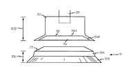
図1では、機械的胸部圧迫デバイス10が、患者1の胸部2に圧迫を加えるように向けられている。胸部圧迫デバイス10は、胸骨2Aに接する胸部圧迫ユニット12を支持し方向付ける支持構造11および背板11Bを含む。胸部圧迫ユニット12は、可逆電気モーター、線形アクチュエータなどであり得るモーター13などの任意の好適な駆動手段を含む。プランジャ14は遠位端14Dおよび近位端14Pを有し、プランジャの近位端14Pはモーター13と機能的に連結している。プランジャの遠位端14Dは、モーター13の作動に伴いハウジングから伸縮する。コントローラ15などのモーター制御ユニットがモーター13と機能的に接続し、マイクロプロセッサを含んでモーターとプランジャの作動を制御する。プランジャアダプタ16はプランジャの遠位端に固着され、圧迫パッド17はプランジャアダプタと取り外し可能に係合する。
In FIG. 1, a mechanical
プランジャアダプタ16の遠位端16Dは、プランジャアダプタと患者の間に圧迫パッドがない状態でプランジャ14が伸長し患者に接触した場合に患者を傷つけないような大きさと形状である。プランジャアダプタ16の遠位端16Dはソケット16Sを含み、該ソケット16Sは、圧迫パッド17の近位端17Pの伸長部17Aなどのキー、部分、または伸長部と呼ばれ得る圧迫パッドの対応する形状の要素と係合する大きさおよび形状である。圧迫パッドの伸長部17Aは、位置決めピンまたはキーとして機能して、位置決めブッシングのプランジャアダプタ16、および胸部圧迫ユニット12が患者に圧迫力を加えるポイントを変えることや患者の胸部で「ずり上がる」のを防止する。
The
使用時、圧迫パッド17は、図2に例示するように胸骨切痕2Nの上方に位置する患者の胸部の加圧箇所18に取り外し可能に固着される。圧迫パッド17は、任意の好適な生体適合性テープまたは粘着剤19などの粘着剤で患者に固着され得る。機械的胸部圧迫デバイス10は、胸部圧迫ユニット12が圧迫パッド17に接した状態で、患者の胸部2の周りに方向付けられる。プランジャ14を伸長させて、圧迫パッド17が患者に適切に配置されているかどうか確認し、また、プランジャアダプタ16と圧迫パッド17および圧迫パッドの伸長部17Aとソケット16Sの嵌合と方向を確認する。適切な整合と方向が確認されると、インターフェース12Aなどの任意の好適なインターフェースによりコントローラ15に指令を与えて、CPRの周期的な圧迫および減圧を実施する。
In use, the compression pad 17 is removably secured to a pressure location 18 on the patient's chest located above the
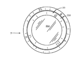
図2に例示するように、プランジャアダプタ24は略円筒形に構成される。圧迫パッド25は、対応する円筒形ソケット26を圧迫パッド25の近位端25Pに含む。プランジャアダプタと圧迫パッドの界面でプランジャアダプタが雄構成要素として機能する構成では、プランジャアダプタは、それが及ぼす単位面積当たりの力が患者の胸に直接加えられても患者を傷つけないような大きさにすべきである。
As illustrated in FIG. 2, the
プランジャアダプタと圧迫パッドの組合せは、前後方向の軸線に沿って大きさを決められて、所定の伸長長さの所定の長さのプランジャを有する胸部圧迫ユニットが、前後方向の寸法が違う各患者に対応することを可能にし得る。 The combination of the plunger adapter and the compression pad is sized along the longitudinal axis, and the chest compression unit having the predetermined length of the predetermined length of the plunger has a different size in the front and rear direction. It may be possible to respond to
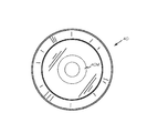
図3、図4、および図5では、プランジャアダプタ30は、高さまたは前後方向の寸法30Dを有し、圧迫パッド31は高さまたは前後方向の寸法31Dを有する。プランジャアダプタ30は、嵌合ねじ、キー溝、位置決めピン、摩擦係合その他など任意の好適な技法によってプランジャ32に取り外し可能に固着される。プランジャアダプタの高さおよび圧迫パッドの高さは、患者の前後方向の寸法ならびにプランジャと圧迫ユニットの長さおよび伸長能力に適合するように個別に選択され得る。圧迫パッド31は、プランジャアダプタ30などの任意の好適なプランジャアダプタのソケット34などの同等の大きさのソケットと係合するような大きさの伸長部33などの伸長部を含む。ソケット34などのプランジャアダプタのソケットの内表面である表面34Aおよび表面34Bは、予め選択されたレベルの粘着性を有する粘着層35などの粘着剤またはコーティングを含んで、アダプタ30などのプランジャアダプタと圧迫パッド31などの圧迫パッドとの制限された係合を維持し、自動胸部圧迫を実施する間プランジャが引っ込むたびに、患者に与える損傷は最小限に抑え予め選択されたレベルの減圧を生成し得る。粘着層35は、圧迫パッドの表面33Aおよび/または33Bにも設けることができる。
3, 4, and 5, the
圧迫パッド31は、患者の胸部の形状に適合するように構成されたほぼ非圧縮性のパッドである。圧迫パッド31などの圧迫パッドは、第1の層31Aおよび第2の層31Bなどの1または複数の層で形成して、患者への圧迫力の加圧を最適化することができる。圧迫パッドの近位または上位端は、プランジャアダプタと係合するための伸長部33などの概ね硬質の伸長部またはソケットである。第1または中心層である層31Aは、可撓性の非圧縮性層であって患者の胸部の形状に適合できる。圧迫パッドの下位または遠位端である第2の層31Bは、可撓性がありほぼ非圧縮性であって患者の胸部の形状に適合でき、1または複数の可撓性カップを含んで1または複数の真空域を圧迫パッドと患者胸部の間に生成し得る。
The
プランジャとプランジャアダプタには好適な係合機構が含まれ、胸部圧迫力に加えて予め選択されたレベルの胸部膨張力を提供し得る。プランジャの遠位端には磁石を設けることができ、対応する磁石または鉄材がプランジャアダプタの近位端に含まれ、プランジャとプランジャアダプタの間に予め選択された保持力を提供し得る。この保持力は、患者の皮膚や基底組織を破るほどの膨張力を患者の胸部に加えることなく、ある程度の膨張力を圧迫の合間に患者の胸部に与えるように選択される。同様に、プランジャの遠位端に電磁石を設けて、調節可能なレベルの保持力を提供するかまたはプランジャアダプタをプランジャから時限解放することができる。 The plunger and plunger adapter include a suitable engagement mechanism that can provide a preselected level of chest expansion force in addition to chest compression force. A magnet may be provided at the distal end of the plunger, and a corresponding magnet or iron material may be included at the proximal end of the plunger adapter to provide a preselected retention force between the plunger and the plunger adapter. This retention force is selected to provide some expansion force to the patient's chest between compressions without applying an expansion force to the patient's chest that would break the patient's skin and base tissue. Similarly, an electromagnet can be provided at the distal end of the plunger to provide an adjustable level of retention or to time release the plunger adapter from the plunger.
図6、図7、および図8に例示するように、プランジャアダプタ40は、圧迫パッド43の伸長部42と係合する大きさと寸法のソケット41を含む。圧迫パッド43は、上述したように患者の胸部に取り外し可能に固着され得る。プランジャ45の引っ込み中に所定の減圧力44を発生させるために、アダプタ側磁石40Mおよび圧迫側磁石43Mなどの磁石をプランジャアダプタ40および圧迫パッド43に組み込み、引力または磁力46などの所定の保持力を提供して、所定の減圧力が超過されるまで圧迫パッド43をプランジャアダプタ40に対し保持することができる。所定のレベルの減圧力は、それよりも低いレベルでは圧迫パッド43がプランジャアダプタ40から離れる前に加圧箇所18の胸部組織が損傷されないレベルに選択される。所定のレベルの保持力46を提供するために、電磁引力、摩擦係合その他など任意の他の好適な技法を用いてもよい。ソケットと伸長部の任意の他の好適な協働構成を用いてもよい。
As illustrated in FIGS. 6, 7, and 8, the
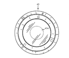
次に図9、図10、および図11を参照すると、プランジャアダプタ50および圧迫パッド51は任意の好適な形状を採用し得る。ここではプランジャアダプタ50の遠位端50Dは八角形であるが、任意の好適な規則的または不規則的な形状が使用できる。遠位端50Dは、圧迫パッド51の近位端51Pと係合するソケット52を含む。圧迫パッド51の遠位端である端51Dは、近位端51Pのキーの形状に関わらず、任意の好適な形状を採用し得る。ここでは近位端51Pはソケット52の形状に適合する六角形として合わせてある。
Referring now to FIGS. 9, 10, and 11, the
図12に例示する患者1は、胸部2に電極アッセンブリ56が固着されている。機械的胸部圧迫デバイス57が、患者1の胸部に圧迫を加えるように向けられている。圧迫パッド56が、用手CPRのフィードバックを提供するのに用いられる胸部圧迫モニター58を含み、該モニターは図13に詳細に例示される。胸部圧迫モニターは、本明細書に参考により援用するHalperinの2002年5月21日に付与された米国特許第6,390,996号「CPR胸部圧迫モニター(CPR Chest Compression Monitor)」によると、圧迫の深さまたは速度(rate)を検出するために設けられる。
A patient 1 illustrated in FIG. 12 has an
プランジャアダプタ59は、図14に例示する胸部圧迫モニターまたはパック58と係合するソケット62を収容する大きさと形状である。胸部圧迫モニターは、圧迫パッドとは別に独立していてもよく、当技術分野ではパックとして知られる。独立型のパックは、治療目的の胸部圧迫のフィードバックを提供するために、患者の胸部の所望箇所61に粘着剤60で粘着され得る。好適な大きさおよび形状のソケット62を有する適切な大きさおよび形状のプランジャアダプタを機械的胸部圧迫デバイス57のプランジャに接続して、上述したような胸部圧迫デバイスの逸れ、ずれ、またはその他胸部圧迫を所望箇所外で実施することを防止できる。プランジャアダプタは、パックの大きさおよび形状に合わせられ、また、任意の好適なセンサー技術または加速度計および/または力センサーなどのセンサーの組合せにより機能する任意の好適な製造業者のパックまたは胸部圧迫モニターを収容するように設けられ得る。
The
本デバイスおよび方法の好ましい実施形態を、それらが開発された環境を参照し説明してきたが、これら実施形態は本発明の原理の単なる例示である。さまざまな実施形態の要素を、その他の種のそれぞれに組み込んで、そのような他種と組み合わせてそれら要素の利点を得ることができ、さまざまな有利な特性を単独かまたは組み合わせて実施形態に用いることができる。本発明の精神および添付の特許請求の範囲から逸脱することなく他の実施形態および構成を発明することができる。 Although preferred embodiments of the present devices and methods have been described with reference to the environment in which they were developed, these embodiments are merely illustrative of the principles of the present invention. Elements of various embodiments can be incorporated into each of the other species and combined with such other species to obtain the benefits of those elements, and various advantageous properties can be used in the embodiments, either alone or in combination. be able to. Other embodiments and configurations may be devised without departing from the spirit of the invention and the scope of the appended claims.
Claims (20)
取付構造、
可逆電気モーター、遠位端および近位端を有するプランジャを含む胸部圧迫ユニットであって、前記プランジャの前記近位端は前記可逆電気モーターに動作可能に連結され、前記プランジャの前記遠位端はハウジングから伸縮し、前記胸部圧迫ユニットは前記取付構造に固着されて患者と係合し、胸部圧迫を実施する、胸部圧迫ユニット、
前記モーターに動作可能に接続され、マイクロプロセッサを含んで、前記電気モーターおよび前記プランジャを制御する、電気モーター制御ユニット、
前記プランジャの前記遠位端に固着されるプランジャアダプタ、および
前記プランジャアダプタと取り外し可能に係合する圧迫パッドを備える、自動胸部圧迫デバイス。 An automatic chest compression device,
Mounting structure,
A chest compression unit including a reversible electric motor, a plunger having a distal end and a proximal end, wherein the proximal end of the plunger is operably connected to the reversible electric motor, and the distal end of the plunger is A chest compression unit that expands and contracts from the housing, and the chest compression unit is secured to the mounting structure and engages with the patient to perform chest compression;
An electric motor control unit operably connected to the motor and including a microprocessor to control the electric motor and the plunger;
An automatic chest compression device, comprising: a plunger adapter secured to the distal end of the plunger; and a compression pad removably engaged with the plunger adapter.
近位端および遠位端を有する略円筒形のアダプタであって、前記近位端は前記プランジャの前記遠位端と取り外し可能に係合し、前記アダプタの前記遠位端は前記圧迫パッドと係合する切頭円錐形ソケットを有するアダプタを備え、
前記圧迫パッドはさらに、前記プランジャの前記切頭円錐形ソケットと取り外し可能に係合するための切頭円錐形伸長部を備える、請求項1に記載の自動胸部圧迫デバイス。 The plunger adapter is
A generally cylindrical adapter having a proximal end and a distal end, wherein the proximal end is removably engaged with the distal end of the plunger, and the distal end of the adapter is connected to the compression pad. An adapter having a frustoconical socket to engage;
The automatic chest compression device of claim 1, wherein the compression pad further comprises a frustoconical extension for releasable engagement with the frustoconical socket of the plunger.
近位端および遠位端を有する略円筒形のアダプタであって、前記近位端は前記プランジャの前記遠位端と取り外し可能に係合し、前記アダプタの前記遠位端は、前記圧迫パッドと係合するアダプタを備え、
前記圧迫パッドはさらに、前記プランジャの前記遠位端と取り外し可能に係合する略円筒形のソケットを備える、請求項1に記載の自動胸部圧迫デバイス。 The plunger adapter is
A generally cylindrical adapter having a proximal end and a distal end, wherein the proximal end is removably engaged with the distal end of the plunger, and the distal end of the adapter is the compression pad With an adapter that engages with
The automatic chest compression device of claim 1, wherein the compression pad further comprises a generally cylindrical socket that removably engages the distal end of the plunger.
前記プランジャアダプタと前記圧迫パッドの間に所定の保持力を発生させる手段を備える、請求項1に記載の自動胸部圧迫デバイス。 The plunger adapter and the compression pad further include:
The automatic chest compression device of claim 1, comprising means for generating a predetermined holding force between the plunger adapter and the compression pad.
プランジャアダプタ側磁石、および
圧迫パッド側磁石を備える、請求項5に記載の自動胸部圧迫デバイス。 The means for generating a predetermined holding force further includes:
The automatic chest compression device according to claim 5, comprising a plunger adapter side magnet and a compression pad side magnet.
取付構造を患者の胸部の周りに設けるステップ、
胸部圧迫ユニットを前記患者の胸骨に接して前記取付構造に固着するステップであって、前記胸部圧迫ユニットは、可逆電気モーター、遠位端および近位端を有するプランジャを含み、前記プランジャの前記近位端は前記可逆電気モーターに動作可能に連結され、前記プランジャの前記遠位端はハウジングから伸縮し、前記患者に胸部圧迫を実施する、ステップ、
前記モーターに動作可能に接続されマイクロプロセッサを含んで前記電気モーターおよび前記プランジャを制御する電気モーター制御ユニットを設けるステップ、
前記プランジャの前記遠位端に固着されるプランジャアダプタを設けるステップ、および
患者の胸骨の上に圧迫パッドを固着するステップであって、前記圧迫パッドは前記プランジャアダプタに取り外し可能に係合する、ステップ、
前記電気モーター制御ユニットによって胸部圧迫を開始するステップを含む、方法。 A method of performing chest compressions on a patient,
Providing an attachment structure around the patient's chest;
Securing a chest compression unit to the attachment structure against the patient's sternum, the chest compression unit including a reversible electric motor, a plunger having a distal end and a proximal end, the proximal of the plunger; A distal end is operably coupled to the reversible electric motor, and the distal end of the plunger extends and retracts from the housing to perform chest compression on the patient;
Providing an electric motor control unit operably connected to the motor and including a microprocessor to control the electric motor and the plunger;
Providing a plunger adapter secured to the distal end of the plunger; and securing a compression pad over a patient's sternum, wherein the compression pad removably engages the plunger adapter. ,
Initiating chest compression by the electric motor control unit.
近位端および遠位端を有する略円筒形のアダプタであって、前記近位端は前記プランジャの前記遠位端と取り外し可能に係合し、前記プランジャアダプタの前記遠位端は前記圧迫パッドと係合する切頭円錐形ソケットを有する、アダプタを備え、
前記圧迫パッドはさらに、前記プランジャアダプタの前記遠位端と取り外し可能に係合する切頭円錐形伸長部を備える、請求項8に記載の方法。 The plunger adapter is
A generally cylindrical adapter having a proximal end and a distal end, wherein the proximal end is removably engaged with the distal end of the plunger, and the distal end of the plunger adapter is the compression pad. An adapter having a frustoconical socket engaging with
The method of claim 8, wherein the compression pad further comprises a frustoconical extension that removably engages the distal end of the plunger adapter.
近位端および遠位端を有する略円筒形のプランジャアダプタであって、前記近位端は前記プランジャの前記遠位端と取り外し可能に係合し、前記圧迫パッドと係合する前記プランジャアダプタの前記遠位端、アダプタを備え、
前記圧迫パッドはさらに、前記プランジャの前記遠位端と取り外し可能に係合する略円筒形のソケットを備える、請求項8に記載の方法。 The plunger adapter is
A generally cylindrical plunger adapter having a proximal end and a distal end, the proximal end of the plunger adapter removably engaging the distal end of the plunger and engaging the compression pad. The distal end comprising an adapter;
9. The method of claim 8, wherein the compression pad further comprises a generally cylindrical socket that removably engages the distal end of the plunger.
前記プランジャの前記遠位端に固着される前記プランジャアダプタ、および
前記プランジャアダプタと取り外し可能に係合する圧迫パッドを備える、改良された胸部圧迫デバイス。 An improved chest compression device of the type having a chest compression unit, an attachment device for attaching the chest compression unit to a patient, the chest compression unit comprising a housing, a distal end and a proximal disposed within the housing A plunger having a distal end, a reversible electric motor, to drive reciprocation of the plunger relative to the housing, and to convert the rotational movement of the motor into linear movement of the plunger to the proximal of the plunger A mechanical device connected to the end, an electric motor control unit connected to the motor and including a microprocessor, a first monitor which serves to monitor the position of the plunger relative to the housing, converts rotational motion into linear motion For the mechanical device or rotor That a second monitor that serves to monitor the position of the plunger, the position which is monitored in the first and second monitors are communicated to the electric motor control unit, wherein the improvement is
An improved chest compression device comprising: the plunger adapter secured to the distal end of the plunger; and a compression pad removably engaged with the plunger adapter.
請求項11に記載の自動胸部圧迫デバイス。 The plunger adapter and the compression pad include complementary concave and convex elements, the plunger adapter and the compression pad removably engaged;
The automatic chest compression device of claim 11.
近位端および遠位端を有する略円筒形のアダプタであって、前記近位端は前記プランジャの前記遠位端と取り外し可能に係合し、前記アダプタの前記遠位端は前記圧迫パッドと係合する切頭円錐形ソケットを有するアダプタを備え、
前記圧迫カップはさらに、前記プランジャの前記切頭円錐形ソケットと取り外し可能に係合する切頭円錐形伸長部を備える、請求項11に記載の自動胸部圧迫デバイス。 The plunger adapter is
A generally cylindrical adapter having a proximal end and a distal end, wherein the proximal end is removably engaged with the distal end of the plunger, and the distal end of the adapter is connected to the compression pad. An adapter having a frustoconical socket to engage;
The automatic chest compression device of claim 11, wherein the compression cup further comprises a frustoconical extension that removably engages the frustoconical socket of the plunger.
近位端および遠位端を有する略円筒形のアダプタであって、前記近位端は前記プランジャの前記遠位端と取り外し可能に係合し、前記アダプタの前記遠位端は、前記圧迫パッドと係合するためのものである、アダプタを備え、
前記圧迫パッドはさらに、前記プランジャの前記遠位端と取り外し可能に係合するための略円筒形のソケットを備える、請求項11に記載の自動胸部圧迫デバイス。 The plunger adapter is
A generally cylindrical adapter having a proximal end and a distal end, wherein the proximal end is removably engaged with the distal end of the plunger, and the distal end of the adapter is the compression pad With an adapter, which is for engaging with
The automatic chest compression device of claim 11, wherein the compression pad further comprises a generally cylindrical socket for releasably engaging the distal end of the plunger.
前記プランジャアダプタと前記圧迫パッドの間に所定の保持力を発生させる手段を備える、請求項11に記載の自動胸部圧迫デバイス。 The plunger adapter and the compression pad further include:
The automatic chest compression device of claim 11, comprising means for generating a predetermined holding force between the plunger adapter and the compression pad.
プランジャアダプタ側磁石、および
圧迫パッド側磁石を備える、請求項15に記載の自動胸部圧迫デバイス。 The means for generating a predetermined holding force further includes:
The automatic chest compression device according to claim 15, comprising a plunger adapter side magnet and a compression pad side magnet.
前記患者の予め選択された力加圧箇所に固着されている圧迫モニターを備え、
前記プランジャアダプタの前記凹形要素は、周期的な胸部圧迫の間、前記圧迫モニターと係合する大きさのソケットである、請求項2に記載の自動胸部圧迫デバイス。 further,
Comprising a compression monitor secured to a pre-selected force-pressing location of the patient;
The automatic chest compression device of claim 2, wherein the concave element of the plunger adapter is a socket sized to engage the compression monitor during periodic chest compressions.
前記予め選択された力加圧箇所に対応して前記患者に固着されている電極アッセンブリを備え、
前記圧迫モニターは前記電極アッセンブリに取り外し可能に固着されている、請求項18に記載の自動胸部圧迫デバイス。 further,
An electrode assembly secured to the patient corresponding to the preselected force pressurization location;
The automatic chest compression device of claim 18, wherein the compression monitor is removably secured to the electrode assembly.
支持構造、
前記患者の胸骨に接する胸部圧迫ユニットであって、モーター、遠位端および近位端を有するプランジャを含み、前記プランジャの前記近位端は前記モーターに機能的に連結され、前記プランジャの前記遠位端は前記圧迫ユニットから伸縮して、予め選択された力加圧箇所で周期的な胸部圧迫を実施する、胸部圧迫ユニット、
前記モーターおよび前記プランジャを制御するマイクロプロセッサ、および
近位端および遠位端を有するプランジャアダプタであって、前記近位端は前記プランジャの前記遠位端に固着され、前記遠位端は圧迫モニターパックと係合する大きさおよび寸法の凹形ソケットを有する、プランジャアダプタを備える、胸部圧迫システム。 A piston-based chest compression system for compressing a patient's chest,
Support structure,
A chest compression unit in contact with the patient's sternum, comprising a plunger having a motor, a distal end and a proximal end, wherein the proximal end of the plunger is operatively coupled to the motor and the distal end of the plunger A chest compression unit that expands and contracts from the compression unit to perform periodic chest compression at a preselected force pressurization location;
A microprocessor for controlling said motor and said plunger; and a plunger adapter having a proximal end and a distal end, said proximal end being secured to said distal end of said plunger, said distal end being a compression monitor A chest compression system comprising a plunger adapter having a concave socket sized and dimensioned to engage the pack.
Applications Claiming Priority (3)
| Application Number | Priority Date | Filing Date | Title |
|---|---|---|---|
| US13/629,434 US8888725B2 (en) | 2012-09-27 | 2012-09-27 | Mechanical chest compression plunger adapter and compression pad |
| US13/629,434 | 2012-09-27 | ||
| PCT/US2013/057509 WO2014051933A1 (en) | 2012-09-27 | 2013-08-30 | Mechanical chest compression plunger adapter and compression pad |
Publications (2)
| Publication Number | Publication Date |
|---|---|
| JP2015530187A true JP2015530187A (en) | 2015-10-15 |
| JP2015530187A5 JP2015530187A5 (en) | 2016-06-30 |
Family
ID=50339556
Family Applications (1)
| Application Number | Title | Priority Date | Filing Date |
|---|---|---|---|
| JP2015534507A Pending JP2015530187A (en) | 2012-09-27 | 2013-08-30 | Mechanical chest compression plunger adapter and compression pad |
Country Status (5)
| Country | Link |
|---|---|
| US (2) | US8888725B2 (en) |
| EP (1) | EP2900196A4 (en) |
| JP (1) | JP2015530187A (en) |
| CN (1) | CN104755057A (en) |
| WO (1) | WO2014051933A1 (en) |
Cited By (2)
| Publication number | Priority date | Publication date | Assignee | Title |
|---|---|---|---|---|
| WO2024029647A1 (en) * | 2022-08-02 | 2024-02-08 | 주식회사 씨유메디칼시스템 | Piston cover of cardiopulmonary resuscitation device |
| WO2024029646A1 (en) * | 2022-08-02 | 2024-02-08 | 주식회사 씨유메디칼시스템 | Piston cap of cardiopulmonary resuscitation device |
Families Citing this family (15)
| Publication number | Priority date | Publication date | Assignee | Title |
|---|---|---|---|---|
| US10143619B2 (en) | 2013-05-10 | 2018-12-04 | Physio-Control, Inc. | CPR chest compression machine performing prolonged chest compression |
| US9320678B2 (en) | 2013-09-30 | 2016-04-26 | Zoll Circulation, Inc. | Chest compression device |
| US10292899B2 (en) | 2014-05-09 | 2019-05-21 | Physio-Control, Inc. | CPR chest compression machine adjusting motion-time profile in view of detected force |
| EP3148499A4 (en) * | 2014-05-29 | 2018-02-21 | Resuscitation International, LLC | Electromechanical chest compression system and method |
| US10004662B2 (en) | 2014-06-06 | 2018-06-26 | Physio-Control, Inc. | Adjustable piston |
| US11246796B2 (en) | 2014-06-06 | 2022-02-15 | Physio-Control, Inc. | Adjustable piston |
| EP4349314A2 (en) | 2014-11-17 | 2024-04-10 | Physio-Control, Inc. | Cpr chest compression machine adjusting motion-time profile in view of detected force |
| DE102016104679A1 (en) * | 2016-03-14 | 2017-09-14 | GS Elektromedizinische Geräte G. Stemple GmbH | Device for cardiopulmonary massage and / or resuscitation |
| US11523966B2 (en) | 2016-12-30 | 2022-12-13 | Physio-Control, Inc. | CPR chest compression system |
| US10835450B2 (en) | 2016-12-30 | 2020-11-17 | Stryker Corporation | CPR chest compression system periodically reminding attendant to check patient |
| DE102017115732A1 (en) * | 2017-07-13 | 2019-01-17 | GS Elektromedizinische Geräte G. Stemple GmbH | Device for cardiopulmonary massage and / or resuscitation |
| US11179293B2 (en) | 2017-07-28 | 2021-11-23 | Stryker Corporation | Patient support system with chest compression system and harness assembly with sensor system |
| US11351086B2 (en) * | 2017-10-23 | 2022-06-07 | Physio-Control, Inc. | CPR chest compression machine |
| CA3083742A1 (en) * | 2017-11-21 | 2019-05-31 | The Hospital For Sick Children | Device for producing continuous negative abdominal pressure |
| US11607368B2 (en) * | 2021-04-07 | 2023-03-21 | The Government of the United States of America, as represented by the Secretary of Homeland Security | Remote modular system for delivering CPR compression |
Family Cites Families (20)
| Publication number | Priority date | Publication date | Assignee | Title |
|---|---|---|---|---|
| US3489140A (en) * | 1960-08-05 | 1970-01-13 | Hyman Hurvitz | Apparatus to restore heartbeat |
| US4770164A (en) | 1980-10-16 | 1988-09-13 | Lach Ralph D | Resuscitation method and apparatus |
| US5738637A (en) | 1995-12-15 | 1998-04-14 | Deca-Medics, Inc. | Chest compression apparatus for cardiac arrest |
| CN2250157Y (en) * | 1996-04-01 | 1997-03-26 | 王年云 | Motor multiple sucker external positive and negative pressure respirator |
| US6142962A (en) | 1997-08-27 | 2000-11-07 | Emergency Medical Systems, Inc. | Resuscitation device having a motor driven belt to constrict/compress the chest |
| US6174295B1 (en) | 1998-10-16 | 2001-01-16 | Elroy T. Cantrell | Chest mounted cardio pulmonary resuscitation device and system |
| US6066106A (en) | 1998-05-29 | 2000-05-23 | Emergency Medical Systems, Inc. | Modular CPR assist device |
| US6616620B2 (en) | 2001-05-25 | 2003-09-09 | Revivant Corporation | CPR assist device with pressure bladder feedback |
| JP3774720B2 (en) * | 2001-09-21 | 2006-05-17 | ホァン、サン−オー | Cardiopulmonary resuscitation equipment |
| US7569021B2 (en) | 2002-03-21 | 2009-08-04 | Jolife Ab | Rigid support structure on two legs for CPR |
| US7226427B2 (en) | 2003-05-12 | 2007-06-05 | Jolife Ab | Systems and procedures for treating cardiac arrest |
| US20050015026A1 (en) * | 2003-07-16 | 2005-01-20 | Well Max Harry | Controlled chest compressor |
| CA2439667A1 (en) * | 2003-09-04 | 2005-03-04 | Andrew Kenneth Hoffmann | Low frequency vibration assisted blood perfusion system and apparatus |
| EP2107901A4 (en) | 2007-01-18 | 2012-11-28 | Jolife Ab | Driving control of a reciprocating cpr apparatus |
| EP2114343A4 (en) | 2007-02-08 | 2013-01-02 | Physio Control Inc | Gas-driven chest compression apparatus |
| CN101873844A (en) * | 2007-06-01 | 2010-10-27 | 心脏科学有限公司 | System, method, and apparatus for assisting a rescuer in resuscitation |
| CN201131896Y (en) * | 2007-11-30 | 2008-10-15 | 侯振才 | Lever type heart lung resuscitators |
| JP5466696B2 (en) | 2008-05-07 | 2014-04-09 | ジョライフ エービー | Cardiopulmonary resuscitation device and method |
| CN201524228U (en) * | 2009-10-19 | 2010-07-14 | 成都爱欧科技发展有限公司 | Cardiopulmonary resuscitator |
| US8702633B2 (en) | 2010-02-12 | 2014-04-22 | Advanced Circulatory Systems, Inc. | Guided active compression decompression cardiopulmonary resuscitation systems and methods |
-
2012
- 2012-09-27 US US13/629,434 patent/US8888725B2/en active Active
-
2013
- 2013-08-30 WO PCT/US2013/057509 patent/WO2014051933A1/en active Application Filing
- 2013-08-30 JP JP2015534507A patent/JP2015530187A/en active Pending
- 2013-08-30 CN CN201380055389.3A patent/CN104755057A/en active Pending
- 2013-08-30 EP EP13840865.3A patent/EP2900196A4/en not_active Withdrawn
-
2014
- 2014-11-18 US US14/546,849 patent/US20150073314A1/en not_active Abandoned
Cited By (2)
| Publication number | Priority date | Publication date | Assignee | Title |
|---|---|---|---|---|
| WO2024029647A1 (en) * | 2022-08-02 | 2024-02-08 | 주식회사 씨유메디칼시스템 | Piston cover of cardiopulmonary resuscitation device |
| WO2024029646A1 (en) * | 2022-08-02 | 2024-02-08 | 주식회사 씨유메디칼시스템 | Piston cap of cardiopulmonary resuscitation device |
Also Published As
| Publication number | Publication date |
|---|---|
| US20140088467A1 (en) | 2014-03-27 |
| WO2014051933A1 (en) | 2014-04-03 |
| EP2900196A4 (en) | 2016-04-20 |
| US20150073314A1 (en) | 2015-03-12 |
| EP2900196A1 (en) | 2015-08-05 |
| US8888725B2 (en) | 2014-11-18 |
| CN104755057A (en) | 2015-07-01 |
Similar Documents
| Publication | Publication Date | Title |
|---|---|---|
| JP2015530187A (en) | Mechanical chest compression plunger adapter and compression pad | |
| JP2015533552A (en) | Method and device for alternating chest compression and decompression | |
| US20210015702A1 (en) | Chest compression device | |
| US10350137B2 (en) | Elevation timing systems and methods for head up CPR | |
| EP2968056B1 (en) | Cpr gurney | |
| EP1622562B1 (en) | System for treating cardiac arrest | |
| JP2015527169A (en) | Method and apparatus for mechanical chest compression with optical alignment | |
| US10667987B2 (en) | Uniform chest compression CPR | |
| US11883351B2 (en) | Systems and methods for improved post-resuscitation recovery | |
| US20010018562A1 (en) | Chest compression device with electro-stimulation | |
| CA2334723A1 (en) | Stimulatory device and methods to enhance venous blood return during cardiopulmonary resuscitation | |
| US20210000685A1 (en) | Device for elevating the head and chest for treating low blood flow states | |
| CA3086201A1 (en) | Device for elevating the head and chest for treating low blood flow states | |
| KR101383051B1 (en) | Fully-automated cardiopulmonary resuscitation apparatus | |
| CN105263459A (en) | Portable oscillating compression system | |
| WO2009147659A1 (en) | Cardiac massage device |
Legal Events
| Date | Code | Title | Description |
|---|---|---|---|
| A521 | Request for written amendment filed |
Free format text: JAPANESE INTERMEDIATE CODE: A523 Effective date: 20160512 |
|
| RD02 | Notification of acceptance of power of attorney |
Free format text: JAPANESE INTERMEDIATE CODE: A7422 Effective date: 20160729 |
|
| RD04 | Notification of resignation of power of attorney |
Free format text: JAPANESE INTERMEDIATE CODE: A7424 Effective date: 20160819 |