JP2015525615A - Four-in-one mattress management system - Google Patents
Four-in-one mattress management system Download PDFInfo
- Publication number
- JP2015525615A JP2015525615A JP2015520436A JP2015520436A JP2015525615A JP 2015525615 A JP2015525615 A JP 2015525615A JP 2015520436 A JP2015520436 A JP 2015520436A JP 2015520436 A JP2015520436 A JP 2015520436A JP 2015525615 A JP2015525615 A JP 2015525615A
- Authority
- JP
- Japan
- Prior art keywords
- mattress
- cover
- air
- similar
- box spring
- Prior art date
- Legal status (The legal status is an assumption and is not a legal conclusion. Google has not performed a legal analysis and makes no representation as to the accuracy of the status listed.)
- Pending
Links
Images


Classifications
-
- A—HUMAN NECESSITIES
- A47—FURNITURE; DOMESTIC ARTICLES OR APPLIANCES; COFFEE MILLS; SPICE MILLS; SUCTION CLEANERS IN GENERAL
- A47C—CHAIRS; SOFAS; BEDS
- A47C21/00—Attachments for beds, e.g. sheet holders, bed-cover holders; Ventilating, cooling or heating means in connection with bedsteads or mattresses
- A47C21/06—Mattress underlays
-
- A—HUMAN NECESSITIES
- A47—FURNITURE; DOMESTIC ARTICLES OR APPLIANCES; COFFEE MILLS; SPICE MILLS; SUCTION CLEANERS IN GENERAL
- A47C—CHAIRS; SOFAS; BEDS
- A47C21/00—Attachments for beds, e.g. sheet holders, bed-cover holders; Ventilating, cooling or heating means in connection with bedsteads or mattresses
Abstract
フォーインワンマットレス管理システム、ならびに、ベッドメイキングすること、マットレスを回転させること、マットレスが回転されている間にベッドスカートを適所に保持すること、例えば、ベッドスカートを再配置するためにマットレスを設置または取り外しおよび再設置することを含む、全てのサイズのベッドと関連付けられる作業を容易にするための方法が開示される。システムは、能動モードと受動モードとを含む。能動モードにおいては、上記で言及された4つ全ての作業を実行することができる。受動モードは選択可能である。受動モードにおいて、マットレスは水平面内で容易に回転することができる。そのモード中、システムは、マットレスが回転されている間に、ベッドスカートを押し下げる。能能動モードにおいて、本発明はベッドメイキングを容易にし、したがって、ハウスキーピングスタッフを効率を増大させ、ハウスキーピングスタッフが部屋の残りの部分に注意を払うのに十分な時間を残す。能動モードはまた、ベッドスカートの設置および交換も容易にする。【選択図】図1Four-in-one mattress management system, as well as making the bed, rotating the mattress, holding the bed skirt in place while the mattress is rotated, e.g. installing or mattress to reposition the bed skirt A method is disclosed for facilitating work associated with all size beds, including removal and re-installation. The system includes an active mode and a passive mode. In the active mode, all four tasks mentioned above can be performed. Passive mode is selectable. In the passive mode, the mattress can easily rotate in a horizontal plane. During that mode, the system pushes down the bed skirt while the mattress is rotated. In the active mode, the present invention facilitates bedmaking, thus increasing the efficiency of the housekeeping staff and leaving sufficient time for the housekeeping staff to pay attention to the rest of the room. The active mode also facilitates bed skirt installation and replacement. [Selection] Figure 1
Description
関連出願の相互参照
本出願は、2012年6月27日に提出された同時係属の米国特許出願第13/534,674号の一部継続出願であり、当該特許出願は、米国特許出願第13/078,385号の一部継続出願であり、当該特許出願は、米国特許出願第12/772,572号、現在は米国特許第8,006,331号の継続出願である。
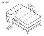
CROSS REFERENCE TO RELATED APPLICATIONS This application is a continuation-in-part of co-pending U.S. Patent Application No. 13 / 534,674 filed June 27, 2012, which is incorporated by reference No. 12 / 772,572, currently a continuation of US Patent No. 8,006,331.
本発明は、フォーインワンマットレス管理システム、ならびに、ベッドメイキングすること、マットレスを回転させること、マットレスが回転されている間にベッドスカートを適所に保持すること、例えば、ベッドスカートを再配置するためにマットレスを設置または取り外しおよび再設置することを含む、全てのサイズのベッドと関連付けられる作業を容易にするための方法に関する。 The present invention provides a four-in-one mattress management system, as well as for making a bed, rotating the mattress, holding the bed skirt in place while the mattress is rotated, eg, to reposition the bed skirt It relates to a method for facilitating the work associated with beds of all sizes, including installing or removing and re-installing mattresses.
従来のベッドは、ボックススプリングまたは下部マットレスまたはプラットフォーム(以下「土台」)および上部マットレスを含む。上部マットレスは相対的に重い物品である。マットレスの重さは、コイルコア、コイルの内径および使用される材料または発泡材料のタイプに応じて変化する。平均的なキングサイズのマットレスの重さは85〜115ポンドである。ラテックスまたは形状記憶発泡体を用いた最高級のキングサイズのマットレスは、300ポンド程度の重さであり得る(http:/www.mattressdirectonline.com)。そのため、ベッドと関連付けられる様々な作業は相対的にかなり重労働である可能性がある。 A conventional bed includes a box spring or lower mattress or platform (hereinafter “base”) and an upper mattress. The upper mattress is a relatively heavy article. The weight of the mattress varies depending on the coil core, the inner diameter of the coil and the type of material or foam material used. The average king size mattress weighs 85-115 pounds. The finest king-size mattresses using latex or shape memory foam can weigh as much as 300 pounds (http://www.mattressdirectonline.com). As such, the various tasks associated with the bed can be relatively heavy labor.
例えば、ホテルおよびモーテルチェーン、ならびに、病院、養護施設および長期療養施設を含む医療施設(以下「商業施設」)は、それらの施設においてフラットシーツしか使用しないことが知られているが、これは、フラットシーツがボックスシーツと比較して費用が低く、それらのそれぞれの全ての備品の中で物品をより少ないままにすることが所望されることに起因する。そのため、そのような施設においてフラットシーツを用いて適切にベッドメイキングするために、ハウスキーピング要員は、上述のように非常に重い可能性がある上部マットレスを持ち上げる必要がある。より詳細には、そのような施設において、上部シーツおよび下部シーツならびに毛布を用いてベッドメイキングされる。上部シーツおよび下部シーツの両方はフラットシーツである。 For example, hotels and motel chains and medical facilities including hospitals, nursing homes and long-term care facilities (hereinafter “commercial facilities”) are known to use only flat sheets in those facilities, This is due to the fact that flat sheets are less expensive than box sheets, and it is desirable to keep fewer articles in all of their respective fixtures. Therefore, in order to properly make beds with flat sheets in such facilities, housekeeping personnel need to lift the upper mattress, which can be very heavy as described above. More particularly, in such facilities, bed making is performed using upper and lower sheets and blankets. Both the upper and lower sheets are flat sheets.
適切にベッドメイキングするために、上部シーツおよび下部シーツは上部マットレスと土台との間に挟み込まれる。より具体的には、下部シーツは、ベッドの各側辺に垂れるシーツの量が等しくなり、ベッドの頭領域および脚領域に垂れるシーツの量が等しくなるように、ベッド上に配置される。余分なシーツはベッドの頭領域および脚領域に挟み込まれ、いわゆる「ホスピタルコーナ」が形成される。次いで、下部シーツの余分が次にマットレスとボックススプリングとの間に挟み込まれる。その後、上部シーツが下部シーツの上に配置され、下部シーツと同じようにホスピタルコーナで配置され挟み込まれるが、頭領域は開いたままにされる。言い換えれば、上部シーツの脚部および側辺部のみがマットレスとボックススプリングとの間に挟まれる。次いで、毛布がベッドの上に配置され、上部シーツと同じように挟み込まれてもよい。 In order to properly make the bed, the upper and lower sheets are sandwiched between the upper mattress and the base. More specifically, the lower sheets are arranged on the bed such that the amount of sheets that hang down on each side of the bed is equal, and the amount of sheets that hang down on the head and leg areas of the bed is equal. Excess sheets are sandwiched between the head and leg regions of the bed, forming a so-called “hospital corner”. The excess of the lower sheet is then sandwiched between the mattress and the box spring. The upper sheet is then placed over the lower sheet and placed and sandwiched at the hospital corner in the same way as the lower sheet, but the head area is left open. In other words, only the leg portion and the side portion of the upper sheet are sandwiched between the mattress and the box spring. A blanket may then be placed on the bed and sandwiched in the same manner as the upper sheets.
マットレスとボックススプリングとの間に上部シーツおよび下部シーツを挟むために、上部マットレスは通常持ち上げられなければならない。上記で言及したように、マットレスは重さが最大300ポンドになる可能性がある。ベッドメイキングするために、ハウスキーピング従業員は、下部シーツについて4回、ならびに上部シーツおよび毛布について3回ずつで、ベッドあたり最大10回マットレスを持ち上げる必要があり得る。ホテル、モーテルまたは医療施設の各ハウスキーピング従業員が一回のシフトで少なくとも20〜30のベッドメイキングすると仮定して、各ハウスキーピング従業員は一般的に、シフトあたり少なくとも150〜200回マットレスを持ち上げることになる。ベッドメイキングは毎日の仕事であるため、ハウスキーピング従業員は、毎日のようにシフトあたり150〜200回マットレスを持ち上げることになる可能性がある。 In order to sandwich the upper and lower sheets between the mattress and the box spring, the upper mattress must usually be lifted. As mentioned above, mattresses can weigh up to 300 pounds. To make a bed, a housekeeping employee may need to lift the mattress up to 10 times per bed, four times for the lower sheets and three times for the upper sheets and blankets. Assuming that each housekeeping employee of a hotel, motel, or medical facility makes at least 20-30 beds per shift, each housekeeping employee typically lifts the mattress at least 150-200 times per shift. It will be. Because bedmaking is a daily job, housekeeping employees can end up lifting mattresses 150-200 times per shift as daily.
そのような持続的で反復的な持ち上げによって従業員が腰痛を発症することになり、結果として従業員が休職し、または深刻な場合には障害を受けることになる。そのような健康問題を軽減するための方策は取られてきている。例えば、単純に下部シーツにボックスシーツを使用することによって、マットレスが持ち上げられる回数が40%低減する。しかしながら、ボックスシーツでは、それによって病院が有名になっている「ホスピタルコーナ」が下部ベッドシーツにもたらされない。その上、下部シーツにボックスシーツを使用しても、上記の例を使用するとハウスキーピング従業員は依然として一日あたり少なくとも90〜160回マットレスを持ち上げる必要がある。 Such persistent and repetitive lifting will cause the employee to develop low back pain, resulting in the employee being absent from work or being severely impaired. Measures have been taken to reduce such health problems. For example, simply using box sheets for the lower sheets reduces the number of times the mattress is lifted by 40%. However, in box sheets, the “Hospital Corner”, which makes the hospital famous, is not brought to the lower bed sheets. Moreover, even if box sheets are used for the lower sheets, using the above example, housekeeping employees still need to lift the mattress at least 90-160 times per day.
ボックスシーツを使用しても、その欠点が除かれるわけではない。例えば、ボックスシーツはフラットシーツよりも費用がかさむ。また、商業施設においてはシーツを頻繁に洗濯するため、ボックスシーツの弾性は消耗していく傾向にある。そのため、そのような施設に使用されるボックスシーツは商業施設での利用においては、ストレートシーツよりも頻繁に交換する必要がある。 The use of box sheets does not eliminate the disadvantages. For example, box sheets are more expensive than flat sheets. Further, since the sheets are frequently washed in commercial facilities, the elasticity of the box sheets tends to be consumed. For this reason, box sheets used in such facilities need to be replaced more frequently than commercial sheets for use in commercial facilities.
ベッドと関連付けられる他の作業も相対的にかなり重労働である可能性がある。これらの作業は、ベッドスカートの有無にかかわらずマットレスを回転させること、ベッドスカートを交換するためにマットレスを取り外すことを含む。 Other tasks associated with the bed may also be relatively heavy labor. These operations include rotating the mattress with or without the bed skirt and removing the mattress to change the bed skirt.
したがって、これらの作業を容易にすることが必要とされている。 Therefore, it is necessary to facilitate these operations.
簡潔には、本発明は、フォーインワンマットレス管理システム、ならびに、ベッドメイキングすること、マットレスを回転させること、マットレスが回転されている間にベッドスカートを適所に保持すること、例えば、ベッドスカートを再配置するためにマットレスを設置または取り外しおよび再設置することを含む、全てのサイズのベッドと関連付けられる作業を容易にするための方法に関する。システムは、能動モードと受動モードとを含む。能動モードにおいては、上記で言及された4つ全ての作業を実行することができる。受動モードは選択可能である。受動モードにおいて、マットレスは水平面内で容易に回転することができる。そのモード中、システムは、マットレスが回転されている間に、存在する場合にはベッドスカートを押し下げることができる。能動モードにおいて、本発明はベッドメイキングを容易にし、したがって、ハウスキーピングスタッフの効率を増大させ、ハウスキーピングスタッフが部屋の残りの部分に注意を払うのに十分な時間を残す。能動モードは、マットレスを回転させること、マットレスが回転されている間にベッドスカートを適所に保持すること、例えば、ベッドスカートを再配置するためにマットレスを設置または取り外しおよび再設置することも容易にする。 Briefly, the present invention provides a four-in-one mattress management system, as well as making a bed, rotating the mattress, holding the bed skirt in place while the mattress is rotated, It relates to a method for facilitating work associated with beds of all sizes, including installing or removing and re-installing mattresses for placement. The system includes an active mode and a passive mode. In the active mode, all four tasks mentioned above can be performed. Passive mode is selectable. In the passive mode, the mattress can easily rotate in a horizontal plane. During that mode, the system can depress the bed skirt, if present, while the mattress is being rotated. In the active mode, the present invention facilitates bedmaking, thus increasing the efficiency of the housekeeping staff and leaving enough time for the housekeeping staff to pay attention to the rest of the room. Active mode makes it easy to rotate the mattress, hold the bed skirt in place while the mattress is rotated, for example to install or remove and re-install the mattress to reposition the bed skirt To do.
本発明のこれらのおよび他の利点は、以下の明細書および添付の図面を参照することによって容易に理解されよう。 These and other advantages of the present invention will be readily understood by reference to the following specification and attached drawings.
本発明は、フォーインワンマットレス管理システム、ならびに、ベッドメイキングすること、マットレスを回転させること、マットレスが回転されている間にベッドスカートを適所に保持すること、例えば、ベッドスカートを再配置するためにマットレスを設置または取り外しおよび再設置することを含む、全てのサイズのベッドと関連付けられる作業を容易にするための方法に関する。 The present invention provides a four-in-one mattress management system, as well as for making a bed, rotating the mattress, holding the bed skirt in place while the mattress is rotated, eg, to reposition the bed skirt It relates to a method for facilitating the work associated with beds of all sizes, including installing or removing and re-installing mattresses.
図1〜図29pは、マットレスを水平面内で回転させるための能動マットレススピンナに関する。図30a〜図43は、上部マットレスを持ち上げる必要なくベッドメイキングすることを容易にするための方法に関する。図44、図45、および図135a〜図138は、上述の様々な実施形態のための代替の縫合パターンを示す。 1 to 29p relate to an active mattress spinner for rotating a mattress in a horizontal plane. 30a-43 relate to a method for facilitating bedmaking without having to lift the upper mattress. 44, 45, and 135a-138 illustrate alternative stitching patterns for the various embodiments described above.
図79〜図81は、ベッドメイキングを容易にするための本発明の使用を示す。図82a〜図82c、図83aおよび図83bは、マットレス回転を示す。図83c、図83d、図84〜図91および図152〜157は、例えば、ベッドスカートを交換するための、マットレスの設置または取り外しおよび再設置を示す。 79-81 illustrate the use of the present invention to facilitate bedmaking. 82a-82c, 83a and 83b illustrate mattress rotation. 83c, 83d, 84-91 and 152-157 illustrate the installation or removal and re-installation of a mattress, for example, to replace a bed skirt.
本発明の様々な実施形態が示されている。図46a〜図47b、図52、図53、図55、図56、図58、図59、図63〜図78、図95、図95a、図95b、図125〜図128、図131a〜図142bおよび図145〜図151は、本発明の単一の反転可能なカバーの実施形態を示す。図49〜図51、図94、図96〜図124、および図143は、本発明の埋め込み実施形態を示す。図129〜図130は、単一の反転可能なカバーおよび埋め込みカバーを有する実施形態を示す。 Various embodiments of the invention are shown. 46a to 47b, 52, 53, 55, 56, 58, 59, 63 to 78, 95, 95a, 95b, 125 to 128, 131a to 142b And FIGS. 145-151 illustrate a single invertible cover embodiment of the present invention. 49-51, 94, 96-124, and 143 illustrate an embedded embodiment of the present invention. FIGS. 129-130 show an embodiment having a single reversible cover and an embedded cover.
本発明は、様々な用途に使用するのに適している。これらの用途は、従来のベッドおよびマットレス、マットレスが封入材によって被覆されている従来のベッドおよびマットレスを含む。本発明の原理は、ジッパ着脱可能下部パネルを有するマットレスカバー内に封入される発泡マットレスにも適用可能である。本発明は、固定および調整可能プラットフォームによって支持されるマットレスに対しても使用することができる。 The present invention is suitable for use in various applications. These applications include conventional beds and mattresses, conventional beds and mattresses where the mattress is covered by an encapsulant. The principle of the present invention is also applicable to a foam mattress enclosed in a mattress cover having a zipper detachable lower panel. The present invention can also be used for mattresses supported by a fixed and adjustable platform.
マットレス管理システム
本発明は、マットレス管理システムに関する。本発明の一実施形態において、マットレス管理システムは、縫合のような任意の従来の手段によってともに締結される2枚の材料から形成される一体成形カバーとして形成される膨脹可能空気ボリューム(膨脹可能空気量)を含む。カバーは、カバーをマットレスの裏面または土台に取り付けるための側部パネルをさらに含む。本明細書において使用される場合、土台は、静止プラットフォーム、調整可能プラットフォームまたはボックススプリングを含むように定義される。
TECHNICAL FIELD The present invention relates to a mattress management system. In one embodiment of the present invention, the mattress management system is an inflatable air volume (inflatable air) formed as a one-piece cover formed from two materials that are fastened together by any conventional means such as stitching. Amount). The cover further includes a side panel for attaching the cover to the back or base of the mattress. As used herein, a foundation is defined to include a stationary platform, an adjustable platform, or a box spring.
マットレス管理システムは、上述のように、能動モード、または、能動モードおよび受動モードから構成されるデュアルモードにおいて操作され得る。空気ポンプからの空気を受け入れるように、空気入り口ノズルが設けられる。マットレス管理システムは、マットレスに関する以下の作業が実行されることを可能にする。これらの作業は、
・ベッドメイキング
・例えば、ベッドスカートを交換するための、マットレスの設置または取り外しおよび再設置、
・水平面内でのマットレスの回転、
・ベッドスカートが使用される応用例における、ベッドスカートの適所への保持
を含む。
The mattress management system can be operated in an active mode or a dual mode consisting of an active mode and a passive mode, as described above. An air inlet nozzle is provided to receive air from the air pump. The mattress management system allows the following operations on the mattress to be performed. These tasks are
-Bed making-Installation or removal and re-installation of mattress, for example to change bed skirts,
・ Rotation of mattress in horizontal plane,
Including holding the bed skirt in place in applications where the bed skirt is used.
マットレス管理システムは、能動モードにおいて使用され得、能動モードにおいては、ベッドメイキングおよびマットレス回転を、空気ポンプからの空気の影響下で行うことができる。デュアルモードにおいては、ベッドメイキングは空気ポンプからの空気流の影響下で行われ、マットレス回転は、受動モードにおいて、カバーの裏面と、マットレスまたは土台の裏側の間の摩擦係数との間の相対摩擦係数に基づいて達成される。マットレス管理システムは、上述の4つの機能のうちの1つまたは複数をもたらすように構成され得る。 The mattress management system can be used in an active mode, in which bed making and mattress rotation can be performed under the influence of air from an air pump. In dual mode, bedmaking is performed under the influence of airflow from the air pump, and mattress rotation is the relative friction between the back of the cover and the coefficient of friction between the back of the mattress or foundation in passive mode. Achieved based on a factor. The mattress management system may be configured to provide one or more of the four functions described above.
マットレス回転は、能動モードまたは受動モードにおいて達成することができる。受動モードにおいて、カバーは最初はマットレスの裏側に取り付けられており、それによって、空気出口孔が、例えば、土台に向かって下向きになっている。受動モードにおいてマットレスを回転させるために、カバーがマットレスから土台へとめくり下ろされる、すなわち、マットレス回転のためにマットレスから取り外されて土台に取り付けられる。ベッドスカートが使用されている場合、マットレスが回転されている間にカバーはベッドスカートを適所に保持することになる。この位置において、カバーの裏面はマットレスの裏面と接している。後述するように、カバーの裏面を相対的に滑らかな表面を用いて形成することによって、マットレスは相対的に容易に回転することができる。マットレスが能動モードにおいて回転される場合、カバーは好ましくは、空気出口孔が上向きになっている土台に取り付けられる。このモードにおいて、マットレスはわずかに浮揚されており、マットレスの回転が容易になる。そのため、カバーは、空気出口孔が上または下に向いている応用例に使用することができる。 Mattress rotation can be achieved in active or passive mode. In the passive mode, the cover is initially attached to the back side of the mattress, so that the air outlet holes are, for example, facing down towards the base. In order to rotate the mattress in the passive mode, the cover is turned down from the mattress to the base, i.e. removed from the mattress and attached to the base for mattress rotation. If a bed skirt is used, the cover will hold the bed skirt in place while the mattress is rotated. In this position, the back surface of the cover is in contact with the back surface of the mattress. As will be described later, the mattress can be rotated relatively easily by forming the back surface of the cover using a relatively smooth surface. When the mattress is rotated in the active mode, the cover is preferably attached to a base with the air outlet holes facing up. In this mode, the mattress is slightly levitated, making it easier to rotate the mattress. Thus, the cover can be used in applications where the air outlet holes are facing up or down.
下記により詳細に説明されるように、能動モードにおいて、本発明の原理は、後述するように、マットレスに関する様々な作業が実行されることを可能にするために、選択された抵抗に対して膨脹可能空気量から空気の制御された放出に基づく。下記に説明されるように、本発明の概念の様々な実施形態が企図される。例えば、膨脹可能空気量は、1つまたは複数の空気出口孔および/または調整可能空気出口弁を含んでもよい。調整可能空気出口弁の様々な実施形態が、下記に例示および説明されるように企図される。空気出口孔または空気出口弁に対する代替形態として、またはそれと組み合わせて、空気袋に使用される材料の多孔性または空気袋と接している材料の多孔性が、制御された放出をもたらすように選択されてもよい。その上、制御された放出は、例えば、空気出口孔と接することになる材料の特性に応じて、空気の放出を制御するために、空気出口孔の上に補助インターフェース材料を取り付けることを含んでもよい。 As described in more detail below, in the active mode, the principles of the present invention expand against selected resistances to allow various operations on the mattress to be performed, as described below. Based on controlled release of air from possible air volume. As described below, various embodiments of the inventive concept are contemplated. For example, the inflatable air volume may include one or more air outlet holes and / or adjustable air outlet valves. Various embodiments of adjustable air outlet valves are contemplated as illustrated and described below. As an alternative to or in combination with an air outlet hole or air outlet valve, the porosity of the material used for the bladder or the porosity of the material in contact with the bladder is selected to provide controlled release. May be. Moreover, controlled release may include, for example, mounting an auxiliary interface material over the air outlet hole to control the release of air depending on the properties of the material that will contact the air outlet hole. Good.
概して、膨脹可能空気量は、例えば、後述するように、縫合または他の従来の方法によってともに取り付けられる後述のような2枚の材料から形成される。下記により詳細に例示および説明するように、本発明の原理は、様々な縫合パターンに適用され、事実、実質的に任意の縫合パターンに適用される。本発明のいくつかの実施形態において、膨脹可能空気量を形成する2枚の材料の中心点が、グロメット、縫合その他によってともに取り付けられる。他の実施形態において、2枚の材料の中心点はともに取り付けられない。膨脹可能空気量に適切な材料が下記に説明される。 Generally, the inflatable air volume is formed from two materials as described below that are attached together, for example, by stitching or other conventional methods, as described below. As illustrated and described in more detail below, the principles of the present invention apply to a variety of stitching patterns, and in fact, to virtually any stitching pattern. In some embodiments of the invention, the central points of the two materials that form the inflatable air volume are attached together by grommets, sutures, and the like. In other embodiments, the center points of the two materials are not attached together. Suitable materials for the amount of inflatable air are described below.
膨脹可能空気量をマットレスまたは土台に取り付けるために、様々な実施形態が企図される。一実施形態において、膨脹可能空気量は、マットレスまたは土台の中に埋め込まれる。他の実施形態において、膨脹可能空気量は側部パネルを含む。これらの側部パネルは、膨脹可能空気量をマットレスまたは土台に取り付けるのに使用される。側部パネルの様々な実施形態が下記に説明される。上述の実施形態に加えて、カバーは封入材またはマットレスプロテクタの1つのパネルとして組み込まれてもよく、これは少なくとも部分的に、マットレス全体にわたって滑る防水であってもよい。この実施形態において、本発明によるカバーは、土台と接することになる封入材の下部パネルに組み込まれる。 Various embodiments are contemplated for attaching an inflatable amount of air to a mattress or foundation. In one embodiment, the amount of inflatable air is embedded in a mattress or foundation. In other embodiments, the inflatable air volume includes side panels. These side panels are used to attach the inflatable air volume to a mattress or foundation. Various embodiments of the side panels are described below. In addition to the embodiments described above, the cover may be incorporated as a panel of encapsulant or mattress protector, which may be at least partially waterproof to slide across the mattress. In this embodiment, the cover according to the invention is incorporated into the lower panel of encapsulant that will be in contact with the foundation.
マットレス管理システムは、導管および空気ポンプをも含む。いくつかの実施形態において、空気ポンプおよび導管は、マットレスまたは土台の外部にある。上述のように、膨脹可能空気量がマットレスまたは土台に埋め込まれる他の応用例において、空気ポンプおよび導管は、マットレスまたは土台に内蔵されてもよい。図46bおよび図47bに示すようないくつかの実施形態において、複数の空気入り口ノズルが、拡張可能空気量の周縁にわたって設けられてもよい。各空気入り口ノズルは、図47cに示すような逆止め弁を設けられてもよい。 The mattress management system also includes a conduit and an air pump. In some embodiments, the air pump and conduit are external to the mattress or foundation. As mentioned above, in other applications where the amount of inflatable air is embedded in the mattress or foundation, the air pump and conduit may be built into the mattress or foundation. In some embodiments as shown in FIGS. 46b and 47b, a plurality of air inlet nozzles may be provided across the periphery of the expandable air volume. Each air inlet nozzle may be provided with a check valve as shown in FIG. 47c.
本発明によるマットレス管理システムを形成するために、本明細書に説明するような本発明の様々な置換例の1つまたは複数を組み合わせることができる。全てのそのような組み合わせが本開示の広い範囲内にあると考えられる。それらの置換例の例示的な組み合わせのみが例示および後述されていることは理解されたい。 One or more of the various permutations of the present invention as described herein can be combined to form a mattress management system according to the present invention. All such combinations are considered to be within the broad scope of this disclosure. It should be understood that only exemplary combinations of these substitutions are illustrated and described below.
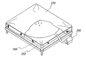
図46a〜図76および図135a〜図138は、マットレス管理システムの様々な例示的な実施形態を示す。図24aおよび図24bは、封入材の実施形態を示す。封入材バージョンの他の実施形態は、空気出口孔、調整可能空気出口弁の使用、および、膨脹可能空気量を形成する2枚のシーツの中心点の取付に関して上述されている。 46a-76 and 135a-138 show various exemplary embodiments of a mattress management system. Figures 24a and 24b show embodiments of encapsulants. Other embodiments of the encapsulant version are described above with respect to the use of air outlet holes, adjustable air outlet valves, and the attachment of the center point of the two sheets that form the inflatable air volume.
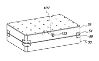
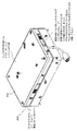
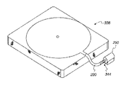
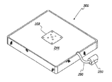
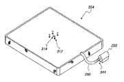
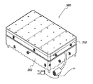
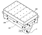
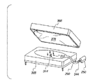
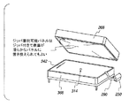
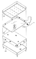
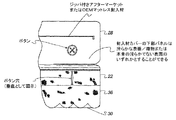
図46aおよび図47aは、それぞれ、例示的な独立したカバー300および303の対、例えば、パッケージ化アフターマーケット付属品を示している。これらのカバー300、302は各々、概して参照符号306によって識別される側部パネルに取り付けられている膨脹可能空気量部分304を含み、これによって、カバー300、302がマットレスまたは土台の裏面(図示せず)に取り付けられることが可能になる。各カバー300、302はそれぞれ、導管290および空気ポンプ250に取り付けるための空気入り口ノズル308および310を含む。
FIGS. 46a and 47a illustrate exemplary
両方のカバー300、302が、概して参照符号312によって識別される複数の空気出口孔を含む。膨脹可能空気量部分304を構成するシーツは、概して参照符号314によって示されるような、それらの中心点においてともに取り付けられる。これらの実施形態の唯一の差は、縫合パターンである。カバー300は、線316によって示されるように矩形縫合パターンによって形成され、カバー302は、線318によって示されるように概して円形の縫合パターンを含む。
Both covers 300, 302 include a plurality of air outlet holes generally identified by
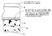
カバー300および302は、パッケージ化アフターマーケット寝具付属品を示し、中心縫合の周囲の4つの空気出口孔、周縁縫合ポリエステル側部スカート材料、および、空気ポンプに取り付けられている空気入り口ホースに対応するための空気入り口を有する、周縁および中心縫合を介してともに接合されている、ナイロンリップストップ織物(一方の面をポリウレタンコートされている)から成る2枚の個々のキングサイズシーツから構成される、単一カバーBedMaker(商標)ユニットを含む。起動されると、ポンプは、マットレスとマットレス土台との間にシーツを挟むのを容易にする目的でマットレス浮揚をもたらすために、2層の接合ナイロン織物によってもたらされる、拡張可能量に対する連続的な空気源を提供する。このサンプルは、BedMaker(商標)技術のパッケージ化アフターマーケット寝具付属品変形例として、マットレスまたは土台のいずれか一方に容易に設置されるように設計されている。
カバー300および302の例示的な仕様を下記に記載する。
・織物300、302: 2×ポリウレタンコートナイロンリップストップのシーツ、各々75インチ×79インチ
・側部パネル306: 1×ポリウレタンコートポリエステルジャージニット材料、奥行き10インチ
・導管290: 1×PVCホース、内径1.5インチ×長さ2.5フィート
・空気ポンプ250: 1×コールマン120V電気クイックポンプ(モデル番号5999C120)
Exemplary specifications for
-
2カバーバージョンのパッケージ化アフターマーケットバージョンが企図される。2カバーバージョンは、中心縫合の周囲の4つの空気出口孔、周縁縫合ポリエステル側部スカート材料、および、空気ポンプに取り付けられている空気入り口ホースに対応するための空気入り口を有する、周縁および中心縫合を介してともに接合されている、ナイロンリップストップ織物(一方の面をポリウレタンコートされている)から成る2枚の個々のキングサイズシーツから構成される。起動されると、ポンプは、マットレスとマットレス土台との間にシーツを挟むのを容易にする目的でマットレス浮揚をもたらすために、2層の接合ナイロン織物によってもたらされる、拡張可能量に対する連続的な空気源を提供する。このサンプルは、BedMaker(商標)技術のパッケージ化アフターマーケット寝具付属品変形例として、マットレスまたは土台のいずれか一方に容易に設置されるように設計されている。加えて、周縁縫合ポリエステル側部スカート材料を有する第2の単一層ナイロンリップストップカバー(一方の面はポリウレタンコートされており/他方の面はスリックコートされている)は、単一カバーBedMaker(商標)ユニットと協働して、このカバーをマットレスの上にめくり上げるか、または、土台の上にめくり下ろすことによるマットレス操作を可能にする。 A two-cover version packaged aftermarket version is contemplated. The two-cover version has four air outlet holes around the central suture, a peripheral stitched polyester side skirt material, and a peripheral and central suture with an air inlet to accommodate the air inlet hose attached to the air pump Composed of two individual king-size sheets of nylon ripstop fabric (polyurethane coated on one side) joined together. When activated, the pump is continuous to the expandable amount provided by the two layers of bonded nylon fabric to provide mattress levitation for the purpose of facilitating the sandwiching of the sheets between the mattress and the mattress base. Provide an air source. This sample, as a variation of BedMaker ™ technology's packaged aftermarket bedding accessories, is designed to be easily installed on either a mattress or foundation. In addition, a second single layer nylon ripstop cover (peripheral stitched polyester side skirt material, one side is polyurethane coated / the other side is slick coated) is a single cover BedMaker ™ In cooperation with the unit, the mattress can be operated by turning the cover up or down on the base.
2カバーバージョンの例示的な仕様を下記に記載する。
・織物: 2×ポリウレタンコートナイロンリップストップのシーツ、各々75インチ×79インチ
・第2のカバーの織物: 1×ポリウレタン/スリックコートナイロンリップストップのシーツ、各々75インチ×79インチ
・側部パネル: 2×ポリウレタンコートポリエステルジャージニット材料、奥行き10インチ
・導管:1×PVCホース、内径1.5インチ×長さ2.5フィート
・空気ポンプ: 1×コールマン120V電気クイックポンプ(モデル番号5999C120)
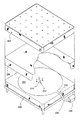
An exemplary specification for the two-cover version is listed below.
• Fabric: 2 x polyurethane coated nylon ripstop sheets, 75 inches x 79 inches each • Second cover fabric: 1 x Polyurethane / slick coated nylon ripstop sheets, 75 inches x 79 inches each • Side panels: 2 x Polyurethane coated polyester jersey knit material, depth 10 inches, conduit: 1 x PVC hose, inner diameter 1.5 inches x length 2.5 feet, air pump: 1 x Coleman 120V electric quick pump (model number 5999C120)
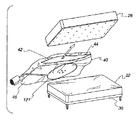
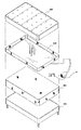
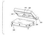
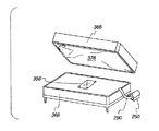
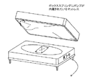
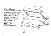
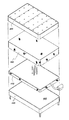
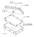
図48および図49は図46aおよび図47aと同様であるが、本発明による埋め込まれているバージョンのカバーを示す。まず図48を参照すると、膨脹可能空気量部分304が、縫合または他の従来の方法のような従来の手段によって、土台322、例えば、ボックススプリングに取り付けられている。膨脹可能空気量部分304は、代替的に、土台322の上にあるマットレス324の裏面に埋め込まれていてもよい。ベッドスカート326は、土台322とマットレス324との間に入れられてもよく、この応用例においては、説明されたような4つ全ての作業はサポートされない。具体的には、ベッドスカート326は、マットレス回転中は押し下げられない。そのため、この実施形態は主としてベッドメイキングに使用される。
48 and 49 are similar to FIGS. 46a and 47a, but show an embedded version of the cover according to the present invention. Referring first to FIG. 48, an inflatable
図49は図48と同様である。この実施形態において、カバー302は上述のように土台306に取り付けられる。図48と図49とに示されている実施形態の間の唯一の差は、上述のような縫合パターンである。
FIG. 49 is the same as FIG. In this embodiment, the
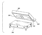
図50および図51は、それぞれ図48および図49と同様である。唯一の差は、この応用例においてはベッドスカートは使用されないという点である。そのため、この応用例においては、ベッドメイキング、マットレス回転、および土台からのマットレスの取り外しに、マットレス管理システムを使用することができる。 50 and 51 are the same as FIGS. 48 and 49, respectively. The only difference is that no bed skirt is used in this application. Thus, in this application, a mattress management system can be used for bed making, mattress rotation, and removal of the mattress from the base.
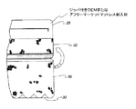
これらの実施形態は、中心縫合の周囲の4つの空気出口孔、周縁縫合ポリエステル側部スカート材料、および、空気ポンプに取り付けられている空気入り口ホースに対応するための空気入り口を有する、周縁および中心縫合を介してともに接合されている、ナイロンリップストップ織物(1枚のシーツの一方の面をポリウレタンコートされており、他方のシーツをポリウレタン/スリックコートされている)から成る2枚の個々のキングサイズシーツから構成される、単一カバーBedMaker(商標)ユニットの埋め込みOEMサンプルに関する。起動されると、ポンプは、マットレスとマットレス土台との間にシーツを挟むのを容易にする目的でマットレス浮揚をもたらすために、2層の接合ナイロン織物によってもたらされる、拡張可能量に対する連続的な空気源を提供する。この実施形態は、BedMaker(商標)技術の内蔵(OEM)変形例をシミュレートするために、マットレス324または土台322のいずれか一方に取り付けるように設計されている。加えて、単一カバー実施形態は、上記マットレスまたは土台から分離し、マットレス操作を容易にするために、ジッパまたは他の取付手段によって、マットレスまたは土台の他方に取り付けることができる。
These embodiments have a perimeter and center with four air outlet holes around the center stitch, a perimeter stitched polyester side skirt material, and an air inlet to accommodate the air inlet hose attached to the air pump. Two individual kings made of nylon ripstop fabric (one sheet is polyurethane coated and the other sheet is polyurethane / slick coated) joined together via stitching It relates to an embedded OEM sample of a single cover BedMaker ™ unit composed of size sheets. When activated, the pump is continuous to the expandable amount provided by the two layers of bonded nylon fabric to provide mattress levitation for the purpose of facilitating the sandwiching of the sheets between the mattress and the mattress base. Provide an air source. This embodiment is designed to attach to either the
OEM埋め込みサンプルの例示的な仕様は以下の通りである。
・織物304: 2×ポリウレタン/スリックコートナイロンリップストップのシーツ、各々75インチ×79インチ
・側部パネル322: 1×ポリウレタンコートポリエステルジャージニット材料、奥行き10インチ
・導管290: 1×PVCホース、内径1.5インチ×長さ2.5フィート
・空気ポンプ250: 1×コールマン120V電気クイックポンプ(モデル番号5999C120)
An exemplary specification for an OEM embedded sample is as follows.
Fabric 304: 2 x polyurethane / slick coated nylon ripstop sheets, 75 inches x 79 inches each Side panel 322: 1 x Polyurethane coated polyester jersey material, depth 10 inches Conduit 290: 1 x PVC hose, ID 1.5 inch x 2.5 feet long, air pump 250: 1 x Coleman 120V electric quick pump (model number 5999C120)
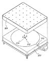
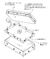
図48〜図51は、土台322またはマットレス324のいずれかに埋め込まれている単一カバー埋め込みバージョンを示す。図41に示すように、代替的な2カバーバージョンも企図される。2カバーバージョンは、中心縫合の周囲の4つの空気出口孔、および、空気ポンプに取り付けられている空気入り口ホースに対応するための空気入り口を有する、周縁および中心縫合を介してともに接合されている、ナイロンリップストップ織物(一方の面をポリウレタンコートされている)から成る2枚の個々のキングサイズシーツから構成される。起動されると、ポンプは、マットレスとマットレス土台との間にシーツを挟むのを容易にする目的でマットレス持ち上げを可能にするために、2層の接合ナイロン織物によってもたらされる、拡張可能量に対する連続的な空気源を提供する。このサンプルは、BedMaker(商標)技術の内蔵(OEM)変形例をシミュレートするために、マットレスまたは土台のいずれか一方に取り付けるように設計されている。加えて、周縁縫合ポリエステル側部スカート材料を有する第2の単一層ナイロンリップストップカバー(一方の面はポリウレタンコートされており/他方の面はスリックコートされている)は、単一カバーBedMaker(商標)ユニットと協働して、このカバーをマットレスの上にめくり上げるか、または、土台の上にめくり下ろすことによるマットレス操作を可能にする。
48-51 show a single cover embedded version embedded in either the base 322 or the
2カバーバージョンの例示的な仕様は以下の通りである。
・織物: 2×ポリウレタンコートナイロンリップストップのシーツ、各々75インチ×79インチ
・第2のカバーの織物: 1×ポリウレタン/スリックコートナイロンリップストップのシーツ、各々75インチ×79インチ
・側部パネル: 1×ポリウレタンコートポリエステルジャージニット材料、奥行き10インチ
・導管: 1×PVCホース、内径1.5インチ×長さ2.5フィート
・空気ポンプ(P): 1×コールマン120V電気クイックポンプ(モデル番号5999C120)
An exemplary specification for the two-cover version is as follows.
• Fabric: 2 x polyurethane coated nylon ripstop sheets, 75 inches x 79 inches each • Second cover fabric: 1 x Polyurethane / slick coated nylon ripstop sheets, 75 inches x 79 inches each • Side panels: 1 x Polyurethane Coated Polyester Jersey Knit Material, Depth 10 inches, Conduit: 1 x PVC Hose, Inner Diameter 1.5 inches x Length 2.5 feet Air Pump (P): 1 x Coleman 120V Electric Quick Pump (Model No. 5999C120 )
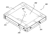
図52〜図62および図65〜図70は、本発明によるマットレス管理システムを形成するカバーの様々な例示的な実施形態を示す。図52、図53、図55、図56、図58、図59は、カバーを形成する2枚のシーツの中心点が参照符号314によって示されるようにともに取り付けられているカバー328、330、332、334、336および338の実施形態を示す。これらの実施形態においては、空気出口孔は設けられず、空気放出は調整可能空気出口弁によって制御される。
52-62 and FIGS. 65-70 illustrate various exemplary embodiments of covers that form a mattress management system according to the present invention. FIGS. 52, 53, 55, 56, 58, and 59 show covers 328, 330, and 332 attached together such that the center point of the two sheets forming the cover is indicated by
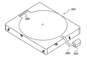
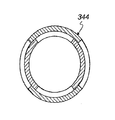
カバー328および330は、図54に示すような、第1のタイプの調整可能空気出口弁340を含んでもよい。図示のように、調整可能空気出口弁340は調整マークを含んでもよく、そのため、例えば、ホテルハウスキーパは、自身の制御下で全てのベッドを同じ値に迅速かつ容易にセットすることができる。
カバー332および334は、図57に示すような、第2のタイプの調整可能空気出口弁342、例えば、ジッパを含んでもよい。図示のように、調整可能空気出口弁342は調整マークを含んでもよく、そのため、例えば、ホテルハウスキーパは、自身の制御下で全てのベッドを同じ値に迅速かつ容易にセットすることができる。
カバー336および338は、図60〜図62に示すような、第3のタイプの調整可能空気出口弁344を含んでもよい。図示のように、調整可能空気出口安全弁344は、空気ポンプ25に取り付けられている導管290に組み込まれる。調整可能空気出口弁344は調整マークを含んでもよく、そのため、例えば、ホテルハウスキーパは、自身の制御下で全てのベッドを同じ値に迅速かつ容易にセットすることができる。
図65〜図70は、図52、図53、図55、図56、図58および図59に示す実施形態と同様である。参照符号346、348、350、352、354および356によって識別されるこれらの実施形態は全て、空気出口孔312と、調整可能空気出口弁340(図54);342(図57)または344(図60〜図62)のうちの1つとを含む。
65 to 70 are the same as the embodiments shown in FIGS. 52, 53, 55, 56, 58 and 59. All of these embodiments, identified by
図63、図64、図71〜図76は、空気流に抵抗するために、空気出口孔の上の別個の材料片を利用する、本発明の例示的な実施形態を示す。本発明の原理の1つは、空気出口孔と接する接合材料が流出する空気流に対するいくらかの抵抗をもたらさなければならないということである。多くの応用例において、マットレスまたは土台の裏面の材料の多孔性は、マットレスの浮揚を引き起こすために十分な抵抗をもたらすのに十分なものである。他の応用例において、インターフェース材料の多孔性は十分でない。それらの応用例において、図示のように、補助インターフェース材料、例えば、ナイロンリップストップの小片が、カバー300、302、350、352、346、348、354および356の空気出口孔312の上に配置される。補助インターフェース材料358は、ベルクロ、縫合または他の取付手段のような様々な従来の取付手段によって、様々なカバー300、302、350、352、346、348、354および356に取り付けられてもよい。
63, 64, 71-76 illustrate exemplary embodiments of the present invention that utilize a separate piece of material above the air outlet holes to resist air flow. One of the principles of the present invention is that the bonding material in contact with the air outlet holes must provide some resistance to the outflowing air flow. In many applications, the porosity of the mattress or backside material is sufficient to provide sufficient resistance to cause the mattress to float. In other applications, the porosity of the interface material is not sufficient. In those applications, as shown, an auxiliary interface material, such as a piece of nylon ripstop, is placed over the air outlet holes 312 of the
図77は、マットレス管理システムの例示的な応用例を示す。この実施形態において、カバー358は、土台364の上にあるマットレス360の裏面に設置される(図78)。ベッドスカート362が土台364上に配置される。図78に示すように、カバーはマットレス360に取り付けられ、それによって、空気孔が高くなり、マットレス360の裏面に接する。代替的に、カバー358は、空気が下向きに流れるようにマットレスに対して並置されていてもよい(図示せず)。
FIG. 77 shows an exemplary application of the mattress management system. In this embodiment, the
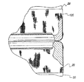
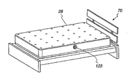
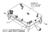
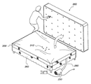
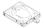
図79〜図81は、ベッドメイキングについての、図78および図79に示すマットレス管理システムの使用を示す。図79および図80に示すように、カバー358の膨脹可能空気量
79-81 illustrate the use of the mattress management system shown in FIGS. 78 and 79 for bedmaking. As shown in FIGS. 79 and 80, the inflatable air amount of the
部分が膨脹し、マットレス360を土台364から持ち上げる。これは、図81に示すように、ベッドシーツ366が容易に挟み込まれるようにするためである。
The portion expands and lifts the
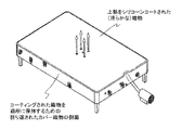
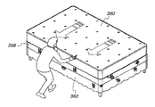
図82aおよび図83aは、図78に示すような応用例における、土台364に対するマットレス360のマットレス回転を示す。図78に示すように、カバー358は最初、マットレス360の裏面に取り付けられている。マットレス360を回転させるために、カバー358がめくり下ろされ、すなわち、マットレス360から分離されて、図82aに示すように、ベッドスカート362の上で土台364に取り付けられる。この位置において、カバー358がベッドスカート362を適所に保持し、一方で図83に示すように、マットレス360が回転される。マットレスが所望の位置まで回転されると、カバー358はマットレス360の裏面に再取付けされてもよい。
82a and 83a show the mattress rotation of the
図82bおよび図82cは図82aおよび図83aと同様であるが、ベッドスカートがなく、マットレスが図24aおよび図24bに示すような封入材内に封入されて示されている。図83bは、図83aと同様であるが、マットレスが図24aおよび図24bに示すような封入材内に封入されて示されている。図83cは図82bと同様であるが、ベッドスカートがなく、カバーがめくり上げられているときに、どのように封入材のジッパを隠しているかを示す。 82b and 82c are similar to FIGS. 82a and 83a, but without the bed skirt, the mattress is shown enclosed in an encapsulant as shown in FIGS. 24a and 24b. FIG. 83b is similar to FIG. 83a, but shows the mattress enclosed in an encapsulant as shown in FIGS. 24a and 24b. FIG. 83c is similar to FIG. 82b but shows how the encapsulant zipper is hidden when the bed skirt is missing and the cover is turned up.
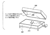
図84〜図91は、例えば、ベッドスカート362を交換するためにプラットフォーム364からマットレス360を取り外し、ベッドスカート362が取り外されて任意選択的に交換された後にプラットフォーム364の上にマットレス360を再設置するためにマットレス管理システムが使用されているところを示す。
84-91, for example, remove the
図84〜図87は、プラットフォーム364からマットレスを取り外すための、空気補助応用例を示す。図88および図89は、空気補助を用いない応用例を示す。図90および図91は、プラットフォーム364の上にマットレス360を再設置しているところを示す。
84-87 show an air assist application for removing the mattress from the
まず図84〜図87を参照すると、カバー358がマットレス360の裏面から分離され、図84に示すように、ベッドスカート362の上でプラットフォーム364に取り付けられる。図85に示すように、空気ポンプ250からの空気補助が、プラットフォーム364に対してマットレス360をわずかに持ち上げ、わずかな労力でマットレスが矢印366の方向に押されることが可能になる。このモーメント矢印は、図87に示すようにマットレス360が土台364から完全に離れるまで、図86に示すようにマットレス360が通常よりも相対的に少ない労力で連続的に押されることを可能にする。
84-87, the
図88および図89は、空気ポンプ250からの空気補助を用いない土台364からのマットレス360の取り外しを示す。この応用例において、カバー358がマットレス360の裏面から分離され、プラットフォーム364に取り付けられて、ベッドスカート362が適所に保持される。この実施形態において、カバー358は、ベッドスカート362を乱すことなくマットレスが押されプラットフォーム364から滑り下ろされることを可能にする相対的に滑らかな表面をもって形成される。
88 and 89 show the removal of
全ての実施形態において、マットレス360がプラットフォーム364から完全に取り外されると、カバー358およびベッドスカート362が取り外される。新たなベッドスカート362がプラットフォーム364の上に配置され、カバー358がベッドスカート362の上でプラットフォーム364に取り付けられる。
In all embodiments, when
空気補助応用例および非空気補助応用例の両方において、マットレス360は、概して図90に示すように、重力の影響下で土台の上で並置される。図示のように、マットレス360は空気出口孔312にかかる。空気補助応用例において、マットレス360は、図91に示すように、少ない労力で押されるか、または定位置へと押されることができる。非空気補助応用例において、マットレスは、図91に示すようにカバー358の滑らかな表面に起因して相対的に少ない労力で定位置へと押されることができる。両方の応用例において、図91に示すように、マットレス360が適所にくると、カバー358がプラットフォーム364から分離され、マットレス360の裏面に再取付される。
In both air-assisted and non-air-assisted applications, the
図152〜図157は図84〜図91と同様であるが、マットレスが図24aまたは図24bに示すような封入材内に封入されているところを示す図である。 FIGS. 152 to 157 are the same as FIGS. 84 to 91, but show the mattress enclosed in the encapsulant as shown in FIG. 24 a or 24 b.
図92は、従来技術において既知であるマットレス366および土台368を示す。図93は、マットレス366および土台368を示し、マットレス366が分解図で示されている。図93を参照すると、マットレス366は、マットレスシェル370と、気泡ゴムマットレス支持体372と、ジッパ(図示せず)によってマットレスシェル370に取り付けられている下部パネル374とを含む。複数の摩擦ストリップ376がパネル374の裏面に位置する。摩擦ストリップ376は、マットレスアセンブリ366が土台368に対して滑るのを防止するのを助ける。土台368は、固定プラットフォーム、例えば、ボックススプリングから構成される。
FIG. 92 shows a
図94〜図121は、図92および図93に示すマットレスアセンブリ366およびプラットフォーム368に組み込まれる、本発明によるマットレス管理システムの様々な実施形態を示す。図122は、調整可能プラットフォームを有する既知のベッドを示す。図123および図124は、図122に示すベッドに組み込まれるマットレス管理システムの様々な実施形態を示す。
94-121 illustrate various embodiments of a mattress management system according to the present invention that is incorporated into the
まず図94〜図121に示す実施形態を参照すると、そのような実施形態のうちの第1の実施形態が図94に示されている。その実施形態においては、ジッパ着脱可能パネル374が、下向きになっている滑らかな表面を有するパネル378に置き換えられている。その上、図96、図98、図100、図102、図104、図106、図108、図110および112に示す実施形態におけるジッパ着脱可能パネルが、同様に下向きになっている滑らかな表面を有するパネル378に置き換えられている。本発明による例示的な2ピースカバー380が、土台368に取付または埋め込まれている。例示的なカバー368は、カバーを形成する2枚のシーツの中心点が、参照符号314によって示すように取り付けられるように構成される。例示的なカバー380はまた、複数の空気出口孔312をも含む。図95は、別の例示的な実施形態を示す。この実施形態において、ジッパ着脱可能パネル374は、滑らかな底面を有するカバー(図示せず)に置き換えられる。カバー382はマットレス366の裏面にジッパ留めされる。カバーは空気出口孔312を含み、カバー382を形成する2枚のシーツの間の接続314を含む。カバー382は、マットレス360が土台368に対してスライドまたは回転することを可能にするためにマットレス366に取り付けられる弾性カラーを含む。カバーの土台368に向いている面は、相対的に滑らかな表面で形成される。土台368に対するマットレス366の回転を防止するために、カラー384はマットレス366から分離され、土台に接続される。
Referring first to the embodiment shown in FIGS. 94-121, a first of such embodiments is shown in FIG. In that embodiment, the zipper
図140a〜図140bは図95と同様であるが、示されており、カバーをマットレスに選択的に固定するための、カバーおよびマットレスの両方の上の取付部材を有して示されている。 FIGS. 140a-140b are similar to FIG. 95, but are shown with mounting members on both the cover and mattress for selectively securing the cover to the mattress.
図96および図97は図94および図95と同様であるが、膨脹可能空気量を作成するのに使用される縫合パターンについては異なっている。図94および図95は概して矩形の空気量を示しており、一方で図96および図97は楕円形または円形の縫合パターンを示している。 96 and 97 are similar to FIGS. 94 and 95, but differ in the stitching pattern used to create the inflatable air volume. 94 and 95 show a generally rectangular air volume, while FIGS. 96 and 97 show an oval or circular stitching pattern.
図98〜図109は図94〜図97と同様であるが、異なる縫合パターンを示し、調整可能空気出口弁を含む。図98および図99は図94および図95と同様であるが、図54に示すような調整可能空気出口弁を含む。図100および図101は図96および図97と同様であるが、調整可能空気弁340を含む。図102および図103は図94および図95と同様であるが、図57に示すような調整可能空気出口弁342を含む。図104および図105は図96および図97と同様であるが、調整可能空気弁342を含む。図106および図107は図94および図95と同様であるが、図60〜図62に示すような調整可能空気出口弁344を含む。図108および図109は図96および図97と同様であるが、調整可能空気出口弁344を含む。
FIGS. 98-109 are similar to FIGS. 94-97 but show a different stitching pattern and include an adjustable air outlet valve. 98 and 99 are similar to FIGS. 94 and 95, but include an adjustable air outlet valve as shown in FIG. FIGS. 100 and 101 are similar to FIGS. 96 and 97 but include an
図110および図111は図94および図95と同様であるが、空気出口孔312の上に補助インターフェース材料の小片358を含む。図112および図113は図96および図97と同様であるが、空気出口孔312の上に補助インターフェース材料の小片358を含む。図95aおよび図95bは図94および図95と同様であるが、それらの実施形態は本明細書において使用されるものとしてのグロメット接続点を示している点が異なっており、グロメットは個々の接続点または連続した縫合とすることができる。グロメットは物理的なグロメットもしくは縫合、または、2枚のシーツをともに接続するための任意の他の従来の技法とすることができる。
110 and 111 are similar to FIGS. 94 and 95 but include a
図114および図115は図113および図112と同様であるが、内蔵ポンプを示している。図116は図97と同様であるが、空気出口孔がない。この実施形態においては、空気は図117に示すような、材料の本来備わっている多孔性によって出る。概して参照符号365によって識別される矢印は、マットレスシェル370(図93)および気泡ゴムマットレス支持体372の材料を通る空気流を示す。図118および図119は図98および図99と同様であるが、空気出口孔を含まない。図120および図121は図102および図103と同様であるが、空気出口孔を含まない。 114 and 115 are similar to FIGS. 113 and 112, but show a built-in pump. FIG. 116 is similar to FIG. 97 but without an air outlet hole. In this embodiment, the air exits due to the inherent porosity of the material, as shown in FIG. The arrows generally identified by reference numeral 365 indicate air flow through the mattress shell 370 (FIG. 93) and cellular rubber mattress support 372 material. 118 and 119 are similar to FIGS. 98 and 99 but do not include air outlet holes. 120 and 121 are similar to FIGS. 102 and 103, but do not include air outlet holes.
図122は、調整可能プラットフォーム上の従来のベッドを示す。概して参照符号390によって識別される調整可能プラットフォームベッドは、土台394を含む。土台394は、基部396と、調整可能プラットフォーム398とを含む。調整可能プラットフォーム398は、基部396によって機械的に支持されている。調整可能プラットフォーム396の位置を調整するのに、電気モータ(図示せず)が使用される。マットレス392は、ジッパ着脱可能パネルを有することが既知である(図示せず)。空気ポンプを使用することなくベッドメイキングを容易にするために、1つまたは複数の滑らかな表面が調整可能プラットフォームベッド390に組み込まれてもよい。具体的には、調整可能プラットフォーム398は、相対的に滑らかな表面を有する材料によって相対的に被覆されてもよい。ジッパ着脱可能パネルは、代替的にまたは加えて、滑らかな表面を有する異なるパネル(図示せず)に置き換えられてもよい。これらの滑らかな表面の一方または両方が、ベッドメイキングを容易にし、したがって受動ベッドメーカを形成するのに使用することができる。
FIG. 122 shows a conventional bed on an adjustable platform. An adjustable platform bed, generally identified by
図123および図124は、調整可能プラットフォーム390に内蔵されているマットレス管理システムを示す。図115は、後述するように、膨脹可能空気量400および吸気ノズル402が、後述するように、ベッドメイキングを容易にするために調整可能プラットフォーム398に取付または埋め込まれている一実施形態を示す。導管404および空気ポンプ406が吸気ノズル402に取り付けられている。導管404および空気ポンプ406は、調整可能プラットフォームベッド390の一端へと延伸してもよく、または、導管および/または吸気ノズル402がプラットフォーム398を通じて延伸している状態で調整可能プラットフォーム398の下に位置してもよい。
123 and 124 show the mattress management system built into the
図124は図123と同様であるが、膨脹可能空気量400がマットレス392の下に示されている。図123に最良に示されているように、マットレス392の裏面はジッパ着脱可能パネル408を含む。図124に示す実施形態において、ジッパ着脱可能パネルは、膨脹可能量400を有するジッパ付きパネル410に置き換えられる。図示のように、空気出口孔を有する円形縫合パターンを有する膨脹可能量400およびともに取り付けられている膨脹可能空気量を形成するシーツの中心。補助インターフェース材料の小片412が空気出口孔の上に取り付けられている。しかしながら、図123および図124は例示的な実施形態であることは理解されたい。膨脹可能量400に対する様々な置換例の全てがこの応用例に適していることは理解されたい。
124 is similar to FIG. 123, but the
図125〜図128は、後述するように単一カバーを形成するために2枚の材料から形成される、概して参照符号420によって識別される膨脹可能空気量の、概して参照符号422〜428によって識別される様々なバージョンを示す。各カバー422〜428は、概して参照符号430によって識別される複数の側部パネルを含む。膨脹可能量420をマットレスまたは土台に対して固定するために、パネル430は、マットレスまたは土台に対する相対的に緊密なグリップをもたらす。単一カバーとして形成される膨脹可能量の作製は下記に説明される。
125-128 are generally identified by reference numerals 422-428 of an inflatable air volume, generally identified by
カバー422〜428は、マットレスの裏面または土台の上に設置されてもよい。カバー422〜428は、本明細書に説明する置換例の全てによって形成されてもよい。図125〜図128は、例示的な実施形態を表しているに過ぎない。
The
図125は、矩形縫合パターンを有し空気出口孔を有しないカバー422を示す。カバー422を構成する2枚のシーツは、参照符号430によって示されるような、2枚のシーツの概ね中心においてともに取り付けられる。この実施形態においては、空気は、参照符号440および図117によって示されるような、材料の多孔性に応じて逃げる。図126は図125と同様であるが、膨脹可能空気量420の円形縫合パターンを示す。図127および図128は図125および図126と同様であるが、空気出口孔312を含む。
FIG. 125 shows a
図129および図130は、本発明によるマットレス管理システムの例示的な応用例を示す。この実施形態において、カバー426(図127)は、マットレス444の裏面に設置される。ベッドスカート445が土台446の上に配置される。この実施形態において、空気流は下向きである。空気はベッドスカートを通じて流れ、下記に説明するように、マットレス444が浮揚されることを可能にするために、土台446の上部パネル448によって妨害される。上部パネル448は、参照符号449によって示されるように、任意の従来の手段、例えば、縫合によって土台の上面に取り付けられてもよい。
FIG. 129 and FIG. 130 show an exemplary application of the mattress management system according to the present invention. In this embodiment, the cover 426 (FIG. 127) is installed on the back surface of the
図130は図129と同様であるが、図128に示すカバー128を利用する。カバー426と428との間の唯一の物理的な差は、縫合パターンである。カバー426は矩形縫合パターンを示しており、一方でカバー428は膨脹可能量の円形縫合パターンを示している。図131および図132は図129および図130と同様であるが、パネル448を含まない。
FIG. 130 is similar to FIG. 129, but utilizes the cover 128 shown in FIG. The only physical difference between
図133および図134は、図129および図130と同様である。唯一の差は、膨脹可能量がマットレスに内蔵されていないことである。 133 and 134 are the same as FIGS. 129 and 130. The only difference is that no inflatable amount is built into the mattress.
後述するように、例示的なマットレス封入材バージョンは、図24aおよび図24bに示すように提供される。例示的なマットレス封入材バージョンは、封入材タイプマットレスプロテクタの下部パネルを交換するように縫合されている、中心縫合の周囲の4つの空気出口孔、および、空気ポンプに取り付けられている空気入り口ホースに対応するための空気入り口を有する、周縁および中心縫合を介してともに接合されている、ナイロンリップストップ織物(一方の面をポリウレタンコートされている)から成る2枚の個々のキングサイズシーツから構成される。起動されると、ポンプは、マットレスとマットレス土台との間にシーツを挟むのを容易にする目的でマットレス持ち上げを可能にするために、2層の接合ナイロン織物によってもたらされる、封入材の裏面に位置する拡張可能量に対する連続的な空気源を提供する。このサンプルは、BedMaker(商標)技術のマットレス封入材変形例として、マットレスの上に設置されるように設計されている。 As described below, an exemplary mattress encapsulant version is provided as shown in FIGS. 24a and 24b. An exemplary mattress encapsulant version includes four air outlet holes around the central suture that are sewn to replace the bottom panel of the encapsulant type mattress protector, and an air inlet hose attached to the air pump. Consists of two individual king-size sheets of nylon ripstop fabric (polyurethane coated on one side) joined together via peripheral and central stitches, with air inlets to accommodate Is done. When activated, the pump is placed on the back of the encapsulant provided by the two layers of bonded nylon fabric to allow the mattress to be lifted for the purpose of facilitating the sandwiching of the sheets between the mattress and the mattress base. Provides a continuous air source for the expandable volume located. This sample is designed to be placed on a mattress as a variation of the BedMaker ™ technology mattress encapsulant.
マットレス封入材バージョンの例示的な仕様を下記に記載する。
・織物: 2×ポリウレタンコートナイロンリップストップのシーツ、各々75インチ×79インチ
・マットレス封入材: 1×Protect−A−Bed AllerZipベッドバッグ/防水寝具封入材
・導管: 1×PVCホース、内径1.5インチ×長さ2.5フィート
・空気ポンプ: 1×コールマン120V電気クイックポンプ(モデル番号5999C120)
Exemplary specifications for mattress encapsulant versions are listed below.
・ Fabric: 2 × polyurethane coated nylon ripstop sheets, each 75 inches × 79 inches ・ Mattress enclosure: 1 × Protect-A-Bed AllerZip bed bag / waterproof bedding enclosure ・ Conduit: 1 × PVC hose,
マットレス封入材バージョンの代替的な2カバー実施形態が企図される。2カバーバージョンは、封入材タイプマットレスプロテクタの下部パネルを交換するように縫合されている、中心縫合の周囲の4つの空気出口孔、および、空気ポンプに取り付けられている空気入り口ホースに対応するための空気入り口を有する、周縁および中心縫合を介してともに接合されている、ナイロンリップストップ織物(一方の面をポリウレタンコートされている)から成る2枚の個々のキングサイズシーツから構成される。起動されると、ポンプは、マットレスとマットレス土台との間にシーツを挟むのを容易にする目的でマットレス持ち上げを可能にするために、2層の接合ナイロン織物によってもたらされる、封入材の裏面に位置する拡張可能量に対する連続的な空気源を提供する。このサンプルは、BedMaker(商標)技術のマットレス封入材変形例として、マットレスの上に設置されるように設計されている。加えて、周縁縫合ポリエステル側部スカート材料を有する第2の単一層ナイロンリップストップカバー(一方の面はポリウレタンコートされており/他方の面はスリックコートされている)は、単一カバーBedMaker(商標)ユニットと協働して、このカバーをマットレスの上にめくり上げるか、または、土台の上にめくり下ろすことによるマットレス操作を可能にする。 Alternative two-cover embodiments of mattress encapsulant versions are contemplated. The two-cover version accommodates four air outlet holes around the central suture that are sewn to replace the bottom panel of the encapsulant type mattress protector, and an air inlet hose attached to the air pump It consists of two individual king-size sheets of nylon ripstop fabric (polyurethane coated on one side) joined together via a perimeter and center stitching, with an air inlet. When activated, the pump is placed on the back of the encapsulant provided by the two layers of bonded nylon fabric to allow the mattress to be lifted for the purpose of facilitating the sandwiching of the sheets between the mattress and the mattress base. Provides a continuous air source for the expandable volume located. This sample is designed to be placed on a mattress as a variation of the BedMaker ™ technology mattress encapsulant. In addition, a second single layer nylon ripstop cover (peripheral stitched polyester side skirt material, one side is polyurethane coated / the other side is slick coated) is a single cover BedMaker ™ In cooperation with the unit, the mattress can be operated by turning the cover up or down on the base.
この実施形態の例示的な仕様を下記に記載する。
・織物: 2×ポリウレタンコートナイロンリップストップのシーツ、各々75インチ×79インチ
・マットレス封入材: 1×Protect−A−Bed AllerZipベッドバッグ/防水寝具封入材
・第2のカバーの織物: 1×ポリウレタン/スリックコートナイロンリップストップのシーツ、各々75インチ×79インチ
・側部パネル: 1×ポリウレタンコートポリエステルジャージニット材料、奥行き10インチ
・導管: 1×PVCホース、内径1.5インチ×長さ2.5フィート
・空気ポンプ: 1×コールマン120V電気クイックポンプ(モデル番号5999C120)
An exemplary specification for this embodiment is described below.
-Fabric: 2 x polyurethane coated nylon ripstop sheets, 75 "x 79" each Mattress enclosure: 1 x Protect-A-Bed AllerZip bed bag / waterproof bedding enclosure-Second cover fabric: 1 x polyurethane / Slick coated nylon ripstop sheets, 75 "x 79" each Side panel: 1 x Polyurethane coated polyester jersey knit material, 10 "deep-Conduit: 1 x PVC hose, 1.5" inside diameter x
Bed Maker(商標)
上部マットレスを持ち上げることなくフラットシーツおよび/または毛布を上部マットレスとボックススプリングとの間に挟むことができるように、上部マットレスの持ち上げを最小限に抑えることによって1つまたは複数のフラットシーツを有する全てのサイズのベッドメイキングを容易にするための独立したシステムおよび方法が開示される。本明細書において使用される場合、ボックススプリングは、ボックススプリングまたはプラットフォームであるものとして理解されたい。
Bed Maker ™
All with one or more flat sheets by minimizing the lifting of the upper mattress so that the flat sheets and / or blankets can be sandwiched between the upper mattress and the box spring without lifting the upper mattress Independent systems and methods are disclosed for facilitating size-making bed making. As used herein, a box spring is to be understood as being a box spring or platform.
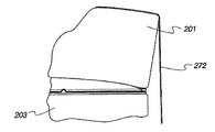
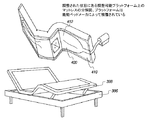
より詳細には、本発明は、マットレスとボックススプリングとの間で中心に位置することができる浮揚デバイスに関する。浮揚デバイスは、空気ポンプまたは他の空気源のような空気源によって駆動され、通常モードおよび能動モードを有する。通常モードにおいて、空気源はオフであり、浮揚デバイスは相対的に平坦である。能動モードにおいて、空気源はオンであり、浮揚デバイスは拡張されて、上部マットレスをボックススプリングに対して持ち上げる。浮揚デバイスをマットレスおよびボックススプリングに対して中心に配置することによって、マットレスの一部分が持ち上げられ、したがって、縁部に沿ってマットレスの重量が軽減される。そのため、能動モード中、フラットシーツおよび毛布を、上部マットレスを持ち上げる必要なく実質的に労力なしにマットレスとボックススプリングとの間に挟むことができる。ベッドメイキングされるとき、空気源は単純にオフにされ、マットレスがボックススプリング上に降下することが可能になる。 More particularly, the present invention relates to a levitation device that can be centrally located between a mattress and a box spring. The levitation device is driven by an air source such as an air pump or other air source and has a normal mode and an active mode. In normal mode, the air source is off and the levitation device is relatively flat. In the active mode, the air source is on and the levitation device is expanded to lift the upper mattress against the box spring. By centering the levitation device relative to the mattress and box spring, a portion of the mattress is lifted, thus reducing the weight of the mattress along the edges. Thus, during active mode, flat sheets and blankets can be sandwiched between the mattress and the box spring without the need to lift the upper mattress and without substantial effort. When the bed is made, the air source is simply turned off and the mattress can be lowered onto the box spring.
上述のように、この実施形態は図30〜図43に示されている。特に、図30〜図37は、浮揚デバイスがマットレスまたはボックススプリングの一方または他方に埋め込まれている実施形態を示す。図38、図39、図42および図43は、浮揚デバイスが、消費者または商業施設によってマットレスまたはボックススプリングのいずれかの上に容易に設置することができる単一カバーとして形成されているアフターマーケット実施形態を示す。図40および図41は、2つのカバーとして形成されている代替的なアフターマーケットデバイスを示す。 As described above, this embodiment is illustrated in FIGS. In particular, FIGS. 30-37 illustrate embodiments in which the levitation device is embedded in one or the other of the mattress or box spring. Figures 38, 39, 42 and 43 show an aftermarket where the levitation device is formed as a single cover that can be easily installed on either a mattress or a box spring by a consumer or commercial facility An embodiment is shown. Figures 40 and 41 show an alternative aftermarket device formed as two covers.
本明細書に記載する本発明は、上述のように、1つまたは複数のフラットシーツを用いて適切にベッドメイキングされるときに有用である。本明細書において使用される場合、フラットシーツは、後述するような標準的なマットレスを被覆するための標準的なサイズを有する布の矩形シーツを意味するように定義される。 The invention described herein is useful when properly bed-made using one or more flat sheets as described above. As used herein, flat sheet is defined to mean a rectangular sheet of fabric having a standard size for covering a standard mattress as described below.
米国標準マットレスおよび標準フラットシーツは下記に記載する。本発明の原理は、非米国マットレスおよびフラットシーツサイズ、ならびに非標準サイズにも適用可能であり、いわゆる「ディープポケット」マットレスおよびフラットシーツにも適用されることに留意されたい。 US standard mattresses and standard flat sheets are described below. It should be noted that the principles of the present invention are applicable to non-US mattress and flat sheet sizes, as well as non-standard sizes, and also apply to so-called “deep pocket” mattresses and flat sheets.

まず図30a〜図37を参照すると、BedMaker(商標)デバイスの第1の実施形態が示されている。この実施形態において、浮揚デバイスは、図30aおよび図30bに示すように、マットレスの裏面またはボックススプリングの上面のいずれかに埋め込まれてもよい。本明細書における定義として、「埋め込まれる(embedded)」は、例えば、縫合によって永続的に取り付けられるか、または、ジッパもしくはベルクロ締結システムのようなファスナシステムを使用してボックススプリングもしくはマットレスの表面に取り外し可能に取り付けられることを意味するように定義される。その上、図30〜図43に示す様々な実施形態は、上向き方向にある浮揚デバイスからの空気流を図示しているが、本発明の原理は、浮揚デバイスからの空気流が概して下向きまたは上向きの方向にある実施形態に適用可能である。 Referring first to FIGS. 30a-37, a first embodiment of a BedMaker ™ device is shown. In this embodiment, the levitation device may be embedded either on the back surface of the mattress or on the top surface of the box spring, as shown in FIGS. 30a and 30b. As defined herein, “embedded” means permanently attached to the surface of a box spring or mattress using, for example, a fastener system such as permanently attached by stitching or a zipper or velcro fastening system. Defined to mean removably attached. Moreover, while the various embodiments shown in FIGS. 30-43 illustrate air flow from a levitation device in an upward direction, the principles of the present invention are such that the air flow from the levitation device is generally downward or upward. It is applicable to the embodiment in the direction of
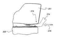
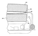
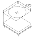
まず図30aを参照すると、上部マットレス201およびボックススプリング203が図示されている。浮揚デバイスは、概して参照符号200によって識別される。浮揚デバイス200は、概して参照符号202によって識別される、縫合または他の様態でともに締結されている2枚の材料から形成される膨脹可能量を含む。図30aに示すように、膨脹可能量は、図30に示すような円形形状、あるいはそれぞれ図44および45に示すような矩形もしくは八角形形状、または図135a〜図138にさらに示すような実質的に任意の形状によって形成されてもよい。
Referring first to FIG. 30a, an
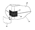
膨脹可能量202は、空気入り口ノズル204と、概して参照符号206によって識別される1つまたは複数の通気孔とを含む。4つの通気孔が図示されている。より多いまたはより少ない通気孔206が使用されてもよい。通気孔206は、空気供給が空気入り口ノズル204に適用されるとき、能動モード中、膨脹可能量202を図33および図34に示すような拡張状態に維持しながら、膨脹可能量202からの過剰な空気を排出するために使用される。
The
膨脹可能量202内に1つまたは複数のエアポケットを生成するために、1つまたは複数のグロメットまたは縫合208が使用されてもよい。図33に最良に示されているように、グロメット208は、空気供給が空気入り口ノズル204(図30a)に接続されているときにエアポケット部分210および212を画定するドーナツ形状エアポケットを生成する。これらのエアポケット部分210、212が、カバー218および上部マットレス201を持ち上げる。たとえポケット部分210および212が側面214および216まで延伸しなくとも、マットレス201は側面214および216に沿って上昇する傾向にある。
One or more grommets or
一実施形態において、浮揚デバイス200は、2枚のシーツから形成される膨脹可能量202、および、第3のシーツを形成するカバー218を含む。カバー218は、空気出口孔からの空気流に抵抗を与えるために使用される。十分な抵抗を与えるための材料がマットレスの裏面または土台から見出される他の実施形態においては、カバー218は取り除かれてもよい。図30a、図33および図34に示すように、例えば、矢印219(図34)、220および222(図33)によって示されるようにポケット部分210および212を充填するために、空気が、空気ポンプ250(図39)によって、矢印217(図33)によって示されるように空気入り口ノズル204に与えられる。過剰な空気は、矢印224および226(図34)によって示されるようにカバー218の下にエアクッションを生成するために、通気孔208(図30a)を通じて排出される。カバー218の下の空気圧を通じて作用するこのエアクッションは、図33および図34に示すように上部マットレス214を持ち上げるために、ポケット210および212の拡張によって生成される上向きの力を支持するのに使用され得る。連続的に空気を供給することによって、カバー218は、例えば、空気供給が空気入り口ノズル204に接続されているときに、概して矢印228(図30a)、230(図32)および232(図34)によって示すように、周縁の周りで過剰な空気を漏出させるためのふるいとして構成される。ふるいは、空気入り口ノズル204への所与の量の空気流に対する上部カバー218からの漏出および通気孔208からの空気流が、図33に最良に示されているように、エアポケット部分210、212(図33)を拡張位置に維持するのに十分であるように構成される。ベッドメイキングされると、空気入り口ノズル204(図30a)への空気供給はオフにされる。その後、ポケット内の空気が通気孔208およびふるいを通じて排出される。
In one embodiment, the
上述のように、浮揚デバイス200は、膨脹可能量202と、カバー218とを含む(図30a)。埋め込み実施形態において、膨脹可能量のいくつかの実施形態がある。一実施形態において、膨脹可能量は、別個のデバイスとして形成され、独立したボックススプリング203に追加され得る。この実施形態において、膨脹可能量202は、PUコートナイロンリップストップもしくはPU/PVCコートナイロンタフタまたは同様もしくはより低い通気性の材料のような、空気不透過性材料の2枚のシーツ234、235から形成される。この実施形態において、これらのシーツは、図30aに示すような円形形状、あるいは、それぞれ図44および45に示すような矩形もしくは八角形形状のような他の形状、または図135a〜図138にさらに示すような実質的に任意の形状に切断される。代替的に、膨脹可能量202の形状は、2枚のシーツを所望の形状にともに縫合によって作成されてもよい。
As described above, the
空気入り口ノズル204はまた、シーツ内に一体的に形成される。シーツはその後、上述のように、織物シーツもしくはポリマーベースのシーツのための縫合、接着剤および/またはヒートシーリングのような、シーツに使用される材料に適した締結方法を使用して所望の形状にともに締結される。
The
独立した膨脹可能量244(図38〜図41)を有する実施形態において、膨脹可能量は、単純にボックススプリング203の上に配置することができ、それによって、空気入り口ノズル204がそこから外向きに延伸する。代替的に、膨脹可能量202(図30a)は、カバー218(図34)の裏面に固定されてもよく、または、ボックススプリング203の上面234に固定されてもよい。両方の実施形態において、カバー218はボックススプリング203に固定される。図32に最良に示されているように、カバー218は、概して参照符号236によって識別される複数の風洞によってふるいを生成するように、ボックススプリング203に固定される。上述のように、ふるいは、矢印228(図30a)によって示すように、カバーの下から過剰な空気を排出するように機能する。
In embodiments having an independent inflatable amount 244 (FIGS. 38-41), the inflatable amount can simply be placed on top of the
通気孔206から放出される空気が、膨脹可能量202とカバー218の裏面との間に形成されるエアポケット部分238および240(図33)に集まることを可能にするために、カバー218は単純に膨脹可能量202(図30a)の上にある。エアポケット238および240内の過剰な空気は、風洞236を通じて排出される(図32、図34)。本明細書において定義されるものとして、過剰な空気とは、上部マットレス201(図33)を持ち上げるのに必要とされる空気圧の量を超える空気圧を意味する。
The
代替的に、膨脹可能空気量202は、上部カバー218に組み込まれてもよく、または、ボックススプリング203の上面234(図30a)に組み込まれてもよい。膨脹可能量202を組み込むことは、複数の方法で達成することができる。1つの方法は、膨脹可能量を2枚の材料から独立した物品として形成し、上述したような適切な手段によって膨脹可能量202を、カバー218またはボックススプリング203の上面234のいずれかに固定することである。
Alternatively, the
代替的に、カバー218または上面234は、膨脹可能量の一部分を形成するのに使用されてもよい。これらの実施形態において、カバー218またはボックススプリング203の上面234は、空気不透過性材料から形成される。この実施形態において、膨脹可能量202は、空気不透過性材料片を膨脹可能量202の形状に切断し、これを上部カバー218またはボックススプリング203の上面234に固定することによって形成される。
Alternatively, cover 218 or
空気不透過性材料に加えて、またはその代わりに、風洞236(図32)を通じた漏出に相当する漏出速度で空気透過性である材料が使用されてもよい。例示的な材料は、ナイロンタフタまたはポリエステルである。そのような実施形態において、風洞236は取り除かれ、上部カバー218は、ボックススプリング203の周縁の周りで完全に取り付けられる。
In addition to or instead of air impermeable material, a material that is air permeable at a leak rate corresponding to leak through the wind tunnel 236 (FIG. 32) may be used. Exemplary materials are nylon taffeta or polyester. In such an embodiment, the
本発明の代替の実施形態が図38、図39、図42および図43に示されている。この実施形態において、概して参照符号242によって識別される浮揚デバイスは、膨脹可能量244と、カバー246とを含む。この実施形態は、ベッドが購入された後に設置することができるアフターマーケット物品である。この実施形態において、カバー246は、ベッドが購入された後に消費者または商業施設のハウスキーパによって設置されることを可能にするためにボックスシーツとして形成される。浮揚デバイス242は上記または下記に説明するように作製されてもよい。図42および図43に示すように、カバー246は、複数の風洞248を有して、または代替的に上述のように形成されてもよい。
An alternative embodiment of the present invention is shown in FIGS. 38, 39, 42 and 43. In this embodiment, the levitation device, generally identified by
図30bは図30aと同様である。図30bにおいては、膨脹可能空気量は、マットレスの裏面に埋め込まれてもよい。図30cおよび図30dは、膨脹可能空気量がカバー内に埋め込まれている実施形態を示す。図139a〜図139gは図30bと同様であり、膨脹可能空気量がマットレスの裏側に埋め込まれており、カバーをマットレスに選択的に固定するための、カバーおよびマットレスの両方の上の取付部材を有して示されている。 FIG. 30b is similar to FIG. 30a. In FIG. 30b, the amount of inflatable air may be embedded in the back surface of the mattress. 30c and 30d show an embodiment in which the inflatable air volume is embedded in the cover. FIGS. 139a-139g are similar to FIG. 30b, with an inflatable air volume embedded in the backside of the mattress, and mounting members on both the cover and the mattress for selectively securing the cover to the mattress. Shown with.
図145〜図148は図139gと同様であるが、カバーが側部パネルを有さず、垂直取付部材がカバーの端部に取り付けられていることを除いて、側部パネルを有しないカバー、および、マットレスを土台に固定するための異なる取付方法を示す。図149〜図151は図139hと同様であるが、カバーが側部パネルを有さず、垂直取付部材がカバーの端部に取り付けられている点が異なる。 FIGS. 145 to 148 are similar to FIG. 139g, except that the cover does not have a side panel and the vertical mounting member is attached to the end of the cover, and does not have a side panel. And different attachment methods for fixing the mattress to the base are shown. FIGS. 149 to 151 are similar to FIG. 139h, except that the cover does not have a side panel and a vertical mounting member is attached to the end of the cover.
図38、図39、図42および図43は図30a〜図37に示す実施形態と同じように動作する。特に、図43を参照すると、空気供給250からの空気が、概して参照符号252によって示されている矢印によって示すように、膨脹可能空気量244内に受け入れられ、それによって、膨脹可能空気量244内のポケット254が拡張され、したがって、カバー218が持ち上がり、それによって、図示され矢印256および258によって示されているように上部マットレス201が持ち上げられる。上述のように、過剰な空気が通気孔(図示せず)を通じて排出され、膨脹可能量244とカバー248との間で移動し、矢印262(図42)によって示すように、または代替的に上述のように、カバー248内に形成されている風洞260を出る。
38, 39, 42 and 43 operate in the same manner as the embodiment shown in FIGS. 30a-37. In particular, referring to FIG. 43, air from the
本発明の第3の実施形態が図40および図41に示されている。この実施形態は、概して参照符号266によって識別される浮揚デバイスであり、2つのカバー268および270を含む。両方のカバー268および270がボックスシーツとして形成され、両方とも、図40に示すような空気が吹き下ろす上部マットレス201、または、図41に示すような空気が吹き上げるボックススプリング203のいずれかに設置される。カバー268および270は、図5に関連して下記に説明するように、または上述したように形成されてもよい。この実施形態において、過剰な空気はカバー268と270との間で自然に逃げ、したがってふるいの必要がなくなる。
A third embodiment of the present invention is shown in FIGS. This embodiment is a levitation device generally identified by
ベッドメイキングするのを容易にするための本発明の実施形態に関連して上述した実施形態の全ては同様に動作し、図35〜図37に関連して説明される。まず図35を参照すると、空気供給250(図43)が空気入り口ノズル204(図30)に取り付けられてオンになり能動モードが規定されると、マットレス201の、端部の周りの部分が持ち上がる。
All of the embodiments described above in connection with the embodiments of the present invention for facilitating bedmaking operate similarly and are described in connection with FIGS. Referring first to FIG. 35, when the air supply 250 (FIG. 43) is attached to the air inlet nozzle 204 (FIG. 30) and turned on to define the active mode, the portion of the
図35に示すように、シーツまたは毛布272はマットレス201の端部からぶら下がって示されている。次に、図36に示すように。毛布またはシーツ272の自由端がマットレス201とボックススプリング203との間に挟まれる。マットレス201の重量は浮揚デバイス200(図30)によって支持されており、マットレスの端部はわずかに持ち上げられているため、消費者または商業ハウスキーパは、マットレス201(図36)とボックススプリング203との間で矢印276の方向に自身の手を容易にかつ実質的に労力なしにスライドさせることが可能である。図36に示すように、その動作がマットレス201の端部214をわずかに持ち上げ、毛布またはシーツ272がカバー218(図30)の上部とマットレス201の底面278(図37)との間に挟まれることを可能にする。矢印280によって示すような浮揚デバイス200(図30)の持ち上げる力が、矢印282(図37)によって示されるようにユーザの手274が退くときにシーツまたは毛布272を適所に保持する。
As shown in FIG. 35, a sheet or
図31に示すように、ユーザは反対の側端部214および216ならびに脚側終端部215へと進み、シーツまたは毛布274を挟み込む。ユーザが側端部214および216ならびに脚側終端部215へと進むと、毛布またはシーツ274のその部分は適所に保持される。挟み込みは、毛布またはシーツ274がマットレス201とボックススプリング203との間に完全に挟まれるまで継続する。概して参照符号286によって示すコーナが、側端部214〜216の前または後のいずれかに挟み込まれてもよい。図31は、ベッドの脚側端部215のコーナが最後に挟み込まれる例示的な応用例を示す。
As shown in FIG. 31, the user proceeds to opposite side ends 214 and 216 and
図32に示すように、ベッドメイキングされている間、過剰な空気が、上述したように、概して参照符号288によって識別される矢印の方向に排出される。ベッドメイキングされると、空気供給250(図39)はオフにされ、通常モードが規定される。このモードにおいて、マットレス201はボックススプリング203上に堅固に載置される。空気供給250およびその導管290は空気供給ノズル204(図30)から分離されてもよい。
As shown in FIG. 32, during bedmaking, excess air is exhausted in the direction of the arrow, generally identified by
図40および図41に示す本発明の重要な態様は、多機能であり、したがってハイブリッドデバイスを形成することである。より具体的には、図40および図41に示す実施形態は、上述したようにベッドメイキングするのを容易にするか、または代替的にマットレスを回転させるために使用することができる。本発明のこの態様を利用するために、両方のカバー268および270がマットレス201またはボックススプリング203の一方または他方に取り付けられ、上述のように、ベッドメイキングモードが規定される。カバー270がマットレス201およびボックススプリング203の一方または他方に取り付けられ、カバー268がマットレス201またはボックススプリング203の他方に取り付けられるようにカバー270を反転させることによって、本発明は、マットレス201を回転させるのに使用することができ、後述するように、マットレス回転モードが規定される。
An important aspect of the present invention shown in FIGS. 40 and 41 is that it is multifunctional and thus forms a hybrid device. More specifically, the embodiments shown in FIGS. 40 and 41 can be used to facilitate bedmaking as described above, or alternatively to rotate the mattress. In order to take advantage of this aspect of the invention, both
浮揚デバイス
浮揚デバイス200は、例えば、図30aに示すような、矩形パターンに構成されている膨脹可能量202を含む。本発明の原理は、代替的なパターンにも適用可能である。例えば、図44は、矩形パターンの膨脹可能量302を有する浮揚デバイス300を示す。図45は、八角形パターンの膨脹可能量312を有する浮揚デバイス310を示す。図135a〜図138は、縫合パターンに対する代替の実施形態を示す。図44および図45は、膨脹可能空気量の空気出口孔の上にカバーを含む実施形態を示す。空気出口孔が、マットレスの裏面の材料、または、空気出口孔と接することになる土台の材料と接している、膨脹可能空気量の2シーツ実施形態。
Levitation device The
浮揚デバイス300および310は、膨脹可能量のパターンを除いて基本的に同じであるため、浮揚デバイス300のみを説明する。図44を参照すると、浮揚デバイス300は、膨脹可能量302および破線で示されている空気入り口ノズル304によって形成される。膨脹可能量302は、破線で示されており概して参照符号306によって識別される1つまたは複数の空気出口孔と、上述のような1つまたは複数のグロメット308または縫合とを含む。図示されている例示的な実施形態において、膨脹可能量302は、カバーによって被覆されており、図38に示す浮揚デバイスと同様に単一カバーアフターマーケットデバイスとして形成され、ボックススプリング203に取り付けられている。
Since the
図40および図41に示すハイブリッド実施形態に使用される材料は、後述するものと同じである。図30〜図37に示す埋め込み実施形態の材料は、下記に記載するようなものであってもよく、PUコートナイロンリップストップおよび/またはPVコートナイロンタフタであってもよい。図38および図39に示すハイブリッド実施形態の材料は、上記に記載したようなものであってもよい。 The materials used in the hybrid embodiment shown in FIGS. 40 and 41 are the same as those described below. The material of the embedding embodiment shown in FIGS. 30-37 may be as described below, and may be PU coated nylon ripstop and / or PV coated nylon taffeta. The material of the hybrid embodiment shown in FIGS. 38 and 39 may be as described above.
Mattress 360(商標)
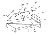
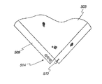
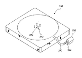
図1〜図29は、ボックススプリングまたはプラットフォームによって担持される、水平面内でマットレスの回転を容易にするためのデバイスに関する。デバイスの第1の実施形態が図5〜図8に示されている。この実施形態において、ボックススプリングに対するマットレスの回転を容易にするために、マットレスとボックススプリングまたはプラットフォームとの間の滑らかな表面が、それらの間の通常の摩擦を低減するために選択的に接触される。滑らかな表面は、2つの別個のカバー、すなわち、ボックススプリングまたはプラットフォームのための第1のカバーおよびマットレスのための第2のカバーによってもたらされる。第1のカバーには、滑らかな表面および滑らかでない表面が設けられる。さらに回転を容易にするために、第2のカバーは、浮揚デバイスの一部分をも含む一方の面に滑らかな表面を含む。第2のカバーの他方の面は、滑らかな表面によって形成されてもよく、または滑らかでない表面によって形成されてもよい。浮揚デバイスは、マットレスを持ち上げ、実質的に労力なしに水平面内でマットレスが回転されることを可能にする空気供給の影響下で、マットレスとボックススプリングとのカバーの間の気柱またはクッションを生成する。マットレスが所望の位置まで回転されると、空気供給が取り除かれ、第1のカバーがマットレスの裏面に取り付けられ、それによって、その滑らかでない表面がボックススプリングもしくはプラットフォームまたはベッドスカートと接し、その滑らかな表面が他方のカバーの滑らかな面および浮揚デバイスと接し、通常動作モードが規定される。
1 to 29 relate to a device for facilitating the rotation of a mattress in a horizontal plane carried by a box spring or platform. A first embodiment of the device is shown in FIGS. In this embodiment, to facilitate rotation of the mattress relative to the box spring, a smooth surface between the mattress and the box spring or platform is selectively contacted to reduce normal friction between them. The The smooth surface is provided by two separate covers, a first cover for the box spring or platform and a second cover for the mattress. The first cover is provided with a smooth surface and a non-smooth surface. To further facilitate rotation, the second cover includes a smooth surface on one side that also includes a portion of the levitation device. The other surface of the second cover may be formed by a smooth surface or may be formed by a non-smooth surface. The levitation device lifts the mattress and creates an air column or cushion between the mattress and box spring cover under the influence of an air supply that allows the mattress to be rotated in a horizontal plane with virtually no effort To do. When the mattress is rotated to the desired position, the air supply is removed and the first cover is attached to the back of the mattress so that its non-smooth surface contacts the box spring or platform or bed skirt and the smooth The surface contacts the smooth surface of the other cover and the levitation device, and a normal mode of operation is defined.
回転動作モードにおいて、第1のカバーはボックススプリングもしくはプラットフォームまたはベッドスカートに取り付けられ、それによって、その滑らかでない表面がそれと接触する。代替的に、図16〜図23に示すように、第1のカバーはボックススプリング内に一体的に組み込まれてもよく、または、滑らかな表面が、プラットフォームベッドの一部分を形成するプラットフォーム上に一体的に形成されてもよい。その実施形態において、ボックススプリングまたはプラットフォームに対するマットレスの運動を妨げるために、マットレスは、図19〜図23に示すように、通常動作モードにおいて取り外し可能ファスナによってボックススプリングまたはプラットフォームに対して固定される。 In the rotational mode of operation, the first cover is attached to a box spring or platform or bed skirt so that its non-smooth surface is in contact with it. Alternatively, as shown in FIGS. 16-23, the first cover may be integrated into the box spring, or the smooth surface may be integrated on the platform forming part of the platform bed. It may be formed automatically. In that embodiment, to prevent movement of the mattress relative to the box spring or platform, the mattress is secured to the box spring or platform by a removable fastener in a normal operating mode, as shown in FIGS.
図5に最良に示されているように、参照符号22によって識別される第1のカバーは、ボックススプリング30のサイズに構成されている矩形パネル26を含む。カバー22は、パネル26の周縁に取り付けられている伸縮可能バンド34を含んでもよい。バンド34は、概して図6に示すように、カバー22がボックススプリング30に取り外し可能に固定されることを可能にする。カバーの面は奥行き9インチになるように作成されてもよく、マットレスまたはボックススプリングの周囲に近密に適合するPUコートポリエステル1方向伸縮(水平)材料から作成されてもよい。
As best shown in FIG. 5, the first cover identified by
図3および図4に最良に示されており、概して参照符号120によって識別される第2のカバーは、マットレス28(図16)のサイズに構成されているパネル124を含む。カバー120は、パネル124の周縁に取り付けられている伸縮可能バンド132を含む。バンド132は、概して図6に示すように、カバー120がマットレス28の裏面に取り外し可能に固定されることを可能にする。
A second cover, best shown in FIGS. 3 and 4 and generally identified by
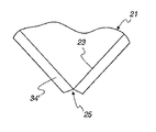
カバー120のパネル124およびバンド132部分はカバー22と同様であるが、カバー120が加えて一体形成浮揚デバイスを含む点が異なっている。より詳細には、拡張可能空気量または空気袋が、カバー120の一部分内に形成される。拡張可能量は、例えば、縫合または他の手段によってパネル124の一部分の上に固定されている上層121から構成されてもよい。図示のように、上層121は、パネル124と同じ材料から形成されてもよく、上述のように、円形形状のような実質的に任意の形状に形成されてもよく、概してカバー120に対して中心に位置してもよい。上層121およびパネル124は、外側に向いている滑らかな表面を有して形成される。カバー120の他方の面は、滑らかな表面または滑らかでない表面のいずれかによって形成されてもよい。
The
膨脹可能量は、吸気ノズル123(図3)と、概して参照符号131および133によって識別される1つまたは複数の空気放出孔とを含む。グロメット129(図4)、または、ヒートシーリング、縫合、接着剤などのような、上部カバー121の中心点をパネル124に取り付けるための他の締結手段が、上層121に対して中心に位置してもよく、上部カバー121上の一点をパネル124に固定し、矢印135aおよび137によって示すような、ノズル123から放出孔131および133への空気流を生成するために参照符号143によって識別される風洞を含む拡張可能量を生成するためにしようされてもよい。
The expandable amount includes an intake nozzle 123 (FIG. 3) and one or more air discharge holes generally identified by
図4に示すように、空気が吸気ノズル123(図3)に加えられると、拡張可能量は図示のように膨脹して、グロメット129に隣接して気柱が形成されることになる。気柱は、マットレス28に埋め込まれているか否かにかかわらず、気柱に接するカバーのような表面を持ち上げまたは浮揚し、これによって、マットレス28の一部分を持ち上げ、マットレス28の周縁に沿った重量のいくらかを軽減する。カバー22の滑らかな表面は上部カバー121の滑らかな表面およびパネル124の滑らかな表面と接しているが、マットレス28(図5)は、概して図2に示すように実質的に労力なしに回転される。マットレス28が所望の位置まで回転されると、カバー22はマットレス28に取り付けられ、それによって、その滑らかでない表面がボックススプリング30と接触させられる。
As shown in FIG. 4, when air is added to the intake nozzle 123 (FIG. 3), the expandable amount expands as shown, and an air column is formed adjacent to the
バンド132および34(図3および図5)は、弾性材料、例えば、スパンデックス、および、メッシュまたは弾性バンドのような伸縮可能材料から形成されてもよく、例えば、縫合によってそれぞれパネル124および26に取り付けられてもよい。代替的に、バンド32、34(図5)は、メッシュまたは伸縮可能織物から形成されてもよい。バンド132および34(図5)はまた、パネル124(図3)、24、26と同じ材料、または、マットレス、マットレス封入材、もしくはボックススプリングの側面と同じ材料から形成されてもよく、後述するような垂直取付方法によってマットレス28およびボックススプリングまたはプラットフォーム30に固定されてもよい。水平取付手段も、マットレス、ボックススプリング、または土台に対するカバーのグリップを緊密にするために使用されてもよい。上述のような、アフターマーケット封入材およびジッパ着脱可能下部パネルを有するマットレスカバーを含む、単一カバーおよびカバーなし実施形態はまた、引き紐(図示せず)または他の取付方法の、2カバー実施形態に関連して説明した取付方法をも含んでもよい。
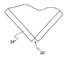
バンド132および34はまた、図28a〜図28bおよび図29a〜図29cに示すような、労働集約度のより低い方法によって形成されてもよい。これらの図面に示す方法は、縫合の量、したがって関連する労力を低減する。単純にするために、1つのカバー22しか記載および図示していない。しかしながら、これらの教示はまた、カバー120のバンド132およびパネル124にも適用される。まず図28aおよび図28bを参照すると、単純にするために、概して参照符号21によって識別されるカバー白地の1つのコーナが示されている。カバー白地21は、矩形材料片の各端部に隣接する、概して参照符号23によって識別される折り線を有する概して矩形の材料片として形成される。図28aに示すように、材料片は例えば、鈍角を規定する各コーナを切り欠きされる。切り欠きは、概して参照符号25によって識別される。バンド34’が、図28bに示すように折られる。参照符号27によって識別される、弾性素材のような可撓性材料片が、切り欠き25を架橋するのに使用される。可撓性材料27は、連続したバンド34’の端部に固定される。当業者によって了解されるように、図28aおよび図28bに示す実施形態は、人件費を大幅に低減する。
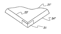
人件費を低減するための第2の技法を図29a〜図29cに示す。この実施形態において、材料白地21’のコーナは切断されて、鈍角ではない切り欠き25’が形成される。例示的な切り欠き25’は概ね90度角で図示されている。この実施形態において、ファスナストリップ29が、切り欠き25’に隣接するバンド34’’の各端部に固定される。協働取り外し可能ファスナストリップ31が、隣接するバンド34’’をともに固定するためにファスナストリップ29に取り付けられてもよい。ファスナストリップ29および31は、ベルクロまたは他のタイプのファスナであってもよい。図29a〜図29Cに示す実施形態は、カバー20が図29cに示すように適所に置かれると、材料白地21’が、取り外し可能ファスナストリップ31によってマットレス28またはボックススプリング30の上に並置され、例えば、図29bに示すように最小として部分的に取り外され、露出した協働ファスナストリップ29に固定されることを可能にする。
A second technique for reducing labor costs is shown in FIGS. 29a-29c. In this embodiment, the corner of the white material 21 'is cut to form a notch 25' that is not obtuse. An exemplary cutout 25 'is illustrated at approximately a 90 degree angle. In this embodiment, a
図29e〜図29jは、カバー、例えば、本明細書に記載する1カバーマットレス管理システムのマットレスまたは土台に対するグリップを緊密にするための様々な技法を示す。図29dおよび図29eに示すように、概して参照符号504によって識別されるスナップ、ベルクロまたはボタンのような従来のファスナが、マットレス500および/または土台502に堅固に固定される。係合するファスナ506がカバー503上に設けられてもよい。図29dに示すように、カバー503は土台502に取り付けられている。カバー503がマットレス500に取り付けられているとき、係合するファスナ500および506は、図29eに示すようにカバー503をマットレスに対して固定するためにともに接合される。カバー503を土台502に固定するために追加の係合するファスナをカバー503および土台上に配置することも企図される。
Figures 29e-29j illustrate various techniques for tightening the grip on a cover, e.g., a mattress or foundation of a one-cover mattress management system described herein. A conventional fastener, such as a snap, velcro or button, generally identified by
図29fおよび図29gは、図29dおよび図29eと同様である。この実施形態において、カバー503には図29dおよび図29eに示すような側部全体のパネル505を設けられず、代わりに、概して参照符号507によって識別されるコーナフラップが設けられる。図29mおよび図29mは図29dおよび図29eと同様であるが、マットレスが図24a、図24bに示すような封入材内に封入されているところを示す。図29oおよび図29pは図29fおよび図29gと同様であるが、マットレスがジッパ付き封入材内に封入されているところを示す。
29f and 29g are similar to FIGS. 29d and 29e. In this embodiment,
図29hおよび図29iは、カバー503の間の緊密なグリップをもたらすための異なる例示的な技法を示す。これらの実施形態において、側部パネルの少なくとも2つ509、510は、図示のようにともに取り付けられていない。図29hにおいて、1つの側部パネル509の端部がループ512を含む。隣接する側部パネル509は、ループ512を受け入れるための、概して参照符号514によって識別される複数のボタンを含む。カバー503のグリップは、ループを掴むために選択される特定のボタンに応じて調整される。図29iは同様であるが、マットレスまたは土台に対するカバー503のグリップを緊密にするために引き紐514を利用する。図29kおよび図29lは、カバー503をマットレスまたは土台に対して固定するための代替的な方法を表す。
FIGS. 29h and 29i illustrate different exemplary techniques for providing a tight grip between the
図29jは、全ての側部パネルが接続されてボックスシーツが形成されているカバー503を示す。この実施形態において、各側部パネルは、概して参照符号516によって示されているストラップおよびベルクロを含んでもよい。この実施形態において、ストラップは、マットレス518または土台(図示せず)に対するカバー503のグリップを緊密にするために、締結位置においてベルクロに締結および取り付けることができる。
FIG. 29j shows a
本発明の重要な態様によれば、カバー22(図5)は、相対的に摩擦係数が低い「滑らかな」面、および、相対的に摩擦係数が高い滑らかでない面を有してもよい。浮揚デバイスの一部分を含む他方のカバー120は、少なくとも1つの滑らかな面を有し、2つの滑らかな面を有してもよい。そのため、2つのカバー120および22の滑らかな表面が選択的に互いに接して配置されると、マットレス28は、下記により詳細に説明されるように、回転動作モードを規定する構成において、1人の人員によって最小限の労力で水平面内で回転することができる。カバー22の滑らかでない面は、選択的にボックススプリング30の被覆されていない表面と接して配置されるために使用される。滑らかでない面によって、通常構成においてマットレスの意図されていない回転を、防止とは言わないまでも低減するために、ボックススプリング30、プラットフォームまたはベッドスカート36の被覆されていない表面をもたらす。
According to an important aspect of the present invention, the cover 22 (FIG. 5) may have a “smooth” surface with a relatively low coefficient of friction and a non-smooth surface with a relatively high coefficient of friction. The
布、および、曲げられ折りやすい他の材料のような、様々な材料が、パネル124、26、カバー10、22に適している。1つのカバー120、22の材料は、滑らかな面および滑らかでない面を有しさえすればよい。滑らかでない面は、滑らかでない材料の一面に滑らかでない裏当てを被覆もしくは縫合または取り付けることによって、滑らかな材料の一面に作成することができる。様々な従来利用可能な材料が、滑らかな面および滑らかでない面を有するカバーに適している。例えば、「30デニールヒートシール可能(裏面)100%ナイロンリップストップ」材料、または、滑らかな面および滑らかでない面において同様の摩擦係数を有する他の材料が、本発明によって使用するのに適している。そのような材料は、ナイロン、例えば、一面に、例えば、ウレタンまたは他の熱可塑性もしくはヒートシール可能コーティングをコーティングされている100%ナイロンであってもよい。そのようなナイロンリップストップ材料は、幅が58〜86インチ幅になり、重量が約1.1〜4.4オンス毎平方ヤードになることが既知である。そのような材料は、必要に応じて様々なマットレス幅に対応するために容易につなぎ合わせることができる。
Various materials are suitable for the
本発明によって使用するのに適したナイロンリップストップ材料は、フロリダ州サラソータ所在のQuest Outfitters(http:/questoutfitters.com)のような様々なソースから入手可能である。Quest Outfittersのタフタ材料は、参照により本明細書に組み込まれる、http:/questoutfitters.com/coated.html#HEAT SEALABLEに詳細に記載されている。適切なナイロンタフタ材料は、コロラド州ラブランド所在のRockywoods(http:/www.rockywoods.com)からも利用可能である。Rockywoodsのタフタ材料は、参照により本明細書に組み込まれる、http:/www.rockywoods.com/Fabrics−Hardware−Patterns−Kits/Medium−Weight−Nylon−Fabrics/Heat−Sealable−70−Denier−Nylon−Taffetaに詳細に記載されている。 Nylon ripstop materials suitable for use with the present invention are available from a variety of sources, such as Quest Outfitters (http://questoutfitters.com), Sarasota, Florida. Quest Outfitters taffeta materials are available from http://questoutfitters.com, which is incorporated herein by reference. com / coated. It is described in detail in html # HEAT SEALABLE. Suitable nylon taffeta materials are also available from Rockywoods (http://www.rockywoods.com) in Loveland, Colorado. Rockywoods taffeta materials are available at http: // www. rockywoods. com / Fabrics-Hardware-Patterns-Kits / Medium-Weight-Nylon-Fabrics / Heat-Sealable-70-Denier-Nylon-Taffeta.
不織材料もまた、滑らかな面および滑らかでない面を有するカバー120、22に使用されてもよい。例えば、DuPont Corporationによって製造され、http:/www2.dupont.com/Products_and_Services/en_VN/nwn.htmlに詳細に記載されているようなTyvek(登録商標)ポリエチレン不織布が使用されてもよい。例えば、Seattle Fabrics,Inc.、http:/www.seattlefabrics.com/nylons.htmlから入手可能であるようなシリコーン含浸ナイロンリップストップのような、2つの滑らかな面を有する他の材料も使用することができる。一面にコーティングが施されている他の材料も使用することができる。その上に、応用例における各カバーに異なる材料を使用することができる。
Nonwoven materials may also be used for the
下記により詳細に説明されるように、本発明のいくつかの実施形態は、拡張可能空気量を含み、空気出口孔または調整可能空気出口弁を含まない。これらの実施形態は、拡張可能空気量からの空気の制御された放出を可能にするために、材料の多孔性に依拠する。 As described in more detail below, some embodiments of the present invention include an expandable air volume and do not include an air outlet hole or an adjustable air outlet valve. These embodiments rely on the porosity of the material to allow controlled release of air from the expandable air volume.
本明細書に説明する様々な実施形態は、滑らかな面および滑らかでない面を有する1つまたは2つのカバーを必要とする。以下の材料がこの目的に適しており、下記に記載される。例えば、以下の例示的な材料が使用されてもよい。
・ポリウレタンラミネートコーティングまたはシリコーンコーティングが施されているワープニット織物
・ポリウレタンラミネートコーティングまたはシリコーンコーティングが施されている不織材料
・ポリウレタン裏当てまたはシリコーンコーティングが施されているトリコット織物
・ポリウレタンラミネートコーティングまたはシリコーンコーティングが施されているステッチボンド織物
・一面にシリコーンコーティングを施され、他方の面にポリウレタンコーティングを施されているナイロンまたはポリエステルリップストップ
・Tietexから入手可能なステッチボンド織物、商品番号944164、型式番号C243、この織物は32%レーヨン、22%ポリエステル、6%トワロンおよび40%コートである。
Various embodiments described herein require one or two covers with smooth and non-smooth surfaces. The following materials are suitable for this purpose and are described below. For example, the following exemplary materials may be used.
・ Warp knit fabric with polyurethane laminate coating or silicone coating ・ Nonwoven material with polyurethane laminate coating or silicone coating ・ Tricot fabric with polyurethane backing or silicone coating ・ Polyurethane laminate coating or silicone Stitch bond fabric with coating • Nylon or polyester ripstop with silicone coating on one side and polyurethane coating on the other side • Stitch bond fabric available from Tietex, product number 944164, model number C243, the fabric is 32% rayon, 22% polyester, 6% twaron and 40% coat.
同様の摩擦係数および多孔性特性を有する材料も使用されてもよい。全てのそのような材料が本開示の広い範囲内にあると考えられる。 Materials with similar coefficient of friction and porosity properties may also be used. All such materials are considered to be within the broad scope of this disclosure.
以下の布地材料も、上述の様々な表面に使用されてもよい。これらの布地材料は、他方の非コーティングまたはコーティング面の摩擦係数に対して滑らかな表面または滑らかでない表面を生成するために摩擦係数を制御するために、下記に示すように一方または両方の面をコーティングされずにまたはコーティングされて使用することができる。
70デニール×70デニールナイロンリップストップ
70デニール×70デニールポリエステルリップストップ
70デニールナイロンおよびポリエステル混紡
70デニールナイロンタフタ
70デニールポリエステルタフタ
30デニールポリエステルまたはナイロンリップストップまたはタフタ
210デニールオックスフォードナイロン
210デニールオックスフォードポリエステル
210デニールナイロンおよびポリエステル混紡
ワープニット織物
ポリ塩化ビニル(PVC)
ポリエチレンシート
ポリプロポレンシート
不織物
オレフィン(別名ポリエチレンおよびポリプロピレン)
ステッチボンド織物
綿混紡
テリー織材料
トリコット
高密度かつ高分子量のポリエチレンフィルム
The following fabric materials may also be used for the various surfaces described above. These fabric materials have one or both surfaces as shown below to control the coefficient of friction to produce a smooth or non-smooth surface relative to the coefficient of friction of the other uncoated or coated surface. It can be used uncoated or coated.
70 denier x 70
Polyethylene sheet Polypropylene sheet Non-woven olefin (also known as polyethylene and polypropylene)
Stitch bond fabric Cotton blend Terry fabric material Tricot High density and high molecular weight polyethylene film
以下のコーティングは、相対的に高い摩擦係数を有する。これらのコーティングが粗いまたは滑らかでない表面に使用されてもよい。
ポリウレタンコート/ラミネート/接着/含浸/裏当て
ポリ塩化ビニル(PVC)コート/ラミネート/接着/含浸/裏当て
熱可塑性プラスチックコート/ラミネート/接着/含浸/裏当て
ゴムコート/ラミネート/接着/含浸/裏当て
ヒートシール可能コート/ラミネート/接着/含浸/裏当て
ウォーターリペレントコート/ラミネート/接着/含浸/裏当て
アクリルコート/ラミネート/接着/含浸/裏当て
接着剤コート/ラミネート/接着/含浸/裏当て
上記のいずれかの混紡コーティング非コート(非コート織物本来の摩擦係数)
以下のコーティングが材料の一面にコーティングされてもよく、相対的に低い摩擦係数をもたらし、したがって、滑らかな表面をもたらすのに使用されてもよい。
シリコーンコート/ラミネート/接着/含浸/裏当て
テフロン(登録商標)コート/ラミネート/接着/含浸/裏当て
石油系コート/ラミネート/接着/含浸/裏当て
上記のいずれかの混紡コーティング織物に織り込まれた滑らかな繊維
非コート(非コート織物本来の摩擦係数)
The following coatings have a relatively high coefficient of friction. These coatings may be used on rough or non-smooth surfaces.
Polyurethane coat / laminate / adhesion / impregnation / backing Polyvinyl chloride (PVC) coat / laminate / adhesion / impregnation / lining Thermoplastic coating / laminate / adhesion / impregnation / lining Rubber coat / laminate / adhesion / impregnation / lining Heat sealable coat / laminate / adhesion / impregnation / backing Water-repellent coat / laminate / adhesion / impregnation / backing Acrylic coat / laminate / adhesion / impregnation / backing Adhesive coat / laminate / adhesion / impregnation / backing Any of the blend coating non-coating (coating coefficient of the uncoated fabric)
The following coatings may be coated on one side of the material and provide a relatively low coefficient of friction and thus may be used to provide a smooth surface.
Silicone Coat / Laminate / Adhesion / Impregnation / Backing Teflon® Coat / Lamination / Adhesion / Impregnation / Backing Petroleum Coat / Lamination / Adhesion / Impregnation / Backing Woven into one of the above blended coated fabrics Smooth fiber Uncoated (Friction coefficient inherent to uncoated fabrics)
まず図5〜図8を参照すると、第1のカバー22はボックススプリング30に取り付けられており、それによって、その滑らかでない面はボックススプリング30と接しており、その滑らかな面は上に向いている。浮揚デバイスの一部分を含む第2のカバー120は、マットレス28の裏面に取り付けられている。回転動作モードにおいて、カバー22はボックススプリング30に取り付けられ、それによって、その滑らかでない面はボックススプリング30と接し、その滑らかな面は上に向き、それによって、その滑らかな面はカバー120の滑らかな表面121および124と接する。通常動作モードにおいて、カバー22はマットレス28に取り付けられ、それによって、その滑らかでない面はボックススプリング28に接し、その滑らかな面はカバー120の滑らかな表面121および124に接し、それによって、ボックススプリング30またはベッドスカート36またはプラットフォームに対するマットレス28の意図されていない運動が低減される。
Referring first to FIGS. 5-8, the
小さい空気供給127が、概して図3に示すような導管125によって吸気ノズル123に接続される。マットレス28を持ち上げるのに必要とされる力は、圧力にマットレス28の面積を乗算した値に比例するため、上部カバー121の面積は、空気ポンプ160によって必要とされる圧力の量によってマットレス28の総重量に分割され得る。図示のように、上部カバー121の直径は、例えば、図3に示すように、マットレス28の幅をわずかに下回るように選択されてもよい。
A
本発明の代替の実施形態が図14および図15に示されている。この実施形態において、吸気ノズル123(図3)と空気ポンプ127との間の導管125’は、マットレス28に部分的に組み込まれてもよい。図16は、導管125’’が拡張可能量の内部と流体連通しており、コネクタ131によってカバー120の外部の空気供給ポンプ127(図3)に接続されているという点で、マットレス28が埋め込み導管125’’を含む、また別の代替の実施形態を示す。
An alternative embodiment of the present invention is shown in FIGS. In this embodiment, the
図9a〜図13は、ベッドスカート36が、概して図9aに示すようにボックススプリング30の上に掛けられている、カバー120および22の一応用例を示す。従来、ボックススプリング30の上に掛けられているベッドスカート36を有するマットレス28の回転は相対的に煩わしい作業であった。本発明は、そのような応用例においてマットレス28の回転を大幅に単純化する。より具体的には、この応用例において、カバー120はマットレス28の裏面に取り付けられ、それによって、その滑らかでない面または滑らかでない面、すなわち、上部カバー121を含まない面が、マットレス28と接し、その滑らかな面、すなわち、上部カバー121を含む面が下に向く。他方のカバー22はベッドスカート36の上でボックススプリング30に取り付けられ、それによって、その滑らかでない面がベッドスカート36と接し、その滑らかな面が上に向き、それによって、図9に示すように、カバー120および22の滑らかな面が互いと接して配置される。その後、マットレス28は、概して図2に示すように、実質的に労力なしに回転することができる。
FIGS. 9a-13 illustrate one application of
マットレス28が所望の位置まで回転された後、カバー22がマットレス30の裏面から分離され、図10aに示すように、カバー120の上でマットレス28に取り付けられる。これによって、カバー22の滑らかでない面がベッドスカート36と接して配置され、マットレス28の意図されていない回転が、防止されるとは言わないまでも、低減される。図10に示すように、マットレス28の回転中、カバー22がベッドスカート36を適所に保持するため、ベッドスカート36は被覆されず、乱されない。
After the
図11〜図13は図9aおよび図10aと同様であり、通常構成においてベッドスカート36がカバー120および22を隠すのに使用される別の応用例を示す。図11を参照すると、ベッドスカート36はマットレス28の周りに配置されており、それによって、その仕上げ面はマットレス28と接しており、その非仕上げ面は外側に向いている。カバー120はベッドスカート36の上でマットレス28に取り付けられており、それによって、その滑らかでない面はベッドスカート36と接しており、その滑らかな面は下に向いている。他方のカバー22はボックススプリング30に取り付けられており、それによって、その滑らかでない面がボックススプリング30と接しており、その滑らかな面が上に向いており、それによって、カバー120および22の滑らかな面が互いと接して配置されている。その後、マットレス30は、1人の人員によって実質的に労力なしに水平面内で回転することができる。マットレス28が所望の位置にくると、カバー120はマットレス28から分離され、他方のカバー22の上でボックススプリング30に取り付けられる。これによって、カバー120の滑らかでない面が、マットレス28と接しているベッドスカートの裏面と接して配置され、それによって、マットレス28の意図されていない回転が低減される。カバー120がボックススプリング30に取り付けられると、ベッドスカート36はボックススプリング30の上に折り下げられ、それによって、図2および図13に示すように第1のカバー120および第2のカバー22の両方が隠れる。図9bおよび図10bは図10aおよび図10bと同様であるが、マットレスが図24aおよび図24bに示すような封入材内に封入されている1カバー実施形態を示す。
FIGS. 11-13 are similar to FIGS. 9a and 10a and show another application in which the
図24a、図24bおよび図25a、図25bは、マットレス封入材バージョンに関し、カバー120が、マットレス28を封止する、防水カバーのような保護カバー40に置き換えられている実施形態を示す。カバー40は、図24aに示され上述したように、浮揚デバイスの一部分を有して形成される。保護カバー40は、相対的にぴったりとした適合をもたらすために、マットレス28のサイズおよび形状に合わせられる。マットレス28が保護カバー40の内部に配置されることを可能にし、それによって浮揚デバイスが下に向くように、保護カバー40の一端に沿って開口42が設けられる。ジッパ44のような従来のファスナが、開口42を閉じるのに使用されてもよい。この実施形態において、カバー40の一方の表面46aに、浮揚デバイスの上部カバー121’またはボックススプリング22(図24a)の上面のように、滑らかな表面46aが設けられる。
FIGS. 24 a, 24 b and 25 a, 25 b show an embodiment in which the
図24aを参照すると、マットレス28およびカバー40は、滑らかな表面46aがボックススプリング30に面するように構成される。カバー22は、滑らかな表面および滑らかでない表面を有して形成される。カバー22はボックススプリング30に取り付けられており、それによって、その滑らかでない面はボックススプリング30と接しており、その滑らかな面は上に向いている。カバー40の滑らかな面46aはカバー22の滑らかな面と協働して、回転モードにおける被覆されたマットレス28の回転を容易にする。カバー22は、上述したように、滑らかな表面および滑らかでない表面を有する。より詳細には、回転動作モードにおいて、カバー22はボックススプリング30に取り付けられ、それによって、その滑らかでない表面はボックススプリング30と接し、その滑らかな表面は、保護カバー40の滑らかな表面に接するために上に向く。このモードにおいて、空気ポンプ127(図3)がオンにされて、拡張可能気柱に浮揚効果をもたらす空気を充填し、供給し続けると、マットレス28は水平面内で労力なしに回転することができる。封入材の代替的な実施形態が図24bおよび図25bに示されている。
Referring to FIG. 24 a, the
2つのカバーを必要とする上述の実施形態に加えて、カバー120および22の一方または両方がそれぞれマットレスまたはボックススプリング30内に一体的に形成される代替の実施形態が下記に説明される。例えば、図16〜図23に示すように、カバー120および22の一方または両方は取り除かれ、マットレス28またはボックススプリング30内に一体的に形成されてもよい。例えば、カバー120が、マットレス28の裏面に一体的に形成されると仮定する。この実施形態において、カバー22はボックススプリング30に取り付けられており、それによって、回転動作モードにおいて、その滑らかでない表面はボックススプリング30と接しており、その滑らかな表面は上に向いている。マットレスが所望の位置まで回転されると、カバー22がマットレス28に取り付けられ、それによって、通常動作モードにおいて、その滑らかでない表面がボックススプリング30と接し、その滑らかな表面がカバー120’の滑らかな表面121’および124’と接する。
In addition to the embodiments described above that require two covers, alternative embodiments are described below in which one or both of the
代替的に、図16〜図18に示すように、両方のカバー120’および22’がそれぞれマットレス28およびボックススプリング30内に一体的に形成されてもよく、それらのそれぞれの滑らかな表面が常に接する。この実施形態において、カバー120’の滑らかな表面121’および124’ならびにカバー22’の滑らかな表面はマットレス28の裏面に取り付けられ、それによって、滑らかな表面が下に向き、マットレス28の裏面と接する。回転動作モードにおいて、カバー120’の滑らかな表面は、ボックススプリング30内に一体的に形成されている滑らかな表面と接する。
Alternatively, as shown in FIGS. 16-18, both
通常動作モードにおいてマットレス28がボックススプリング30に対して動くのを防止するために、ファスナ、例えば、ベルクロファスナが、マットレス28およびボックススプリング30の両方のコーナに設けられてもよい。特に、持続性ファスナストリップ54が、図16、図17および図19に示すようにマットレス28のコーナに設けられる。同様に、持続性ファスナストリップ56が、ボックススプリング30のコーナに設けられる。図17および図19に示すように、マットレス28がボックススプリング30と正確に位置合わせされると、マットレス28上の持続性ファスナストリップ54、56はボックススプリング30上の持続性ファスナストリップ56と位置合わせされる。ボックススプリング30に対してマットレス28を固定するために、取り外し可能協働ファスナストリップ58が、図18および図20に示すような持続性ファスナストリップ54および56に選択的に取り付けられ、通常動作モードが規定される。取り外し可能ファスナストリップ58は、マットレス28を回転させるために単純に取り外され、マットレス28が回転されると再配置される。
To prevent the
本発明の代替の実施形態が図143および図144aに示されている。この実施形態において、マットレスは、例えば、図144bに示すような垂直取付デバイスによって土台に固定される。 An alternative embodiment of the present invention is shown in FIGS. 143 and 144a. In this embodiment, the mattress is secured to the base by a vertical mounting device, for example as shown in FIG. 144b.
2つの代替の実施形態が図21〜図23に示されている。図21および図22に示す実施形態において、持続性ファスナストリップ60および62が、マットレス28およびボックススプリング30が一緒になる端部に隣接して、マットレス28およびボックススプリング30の周縁の周りに位置する。図22に示すように、協働取り外し可能ファスナストリップ64が、それぞれマットレス28およびボックススプリング30上の持続性ファスナストリップ60および62に取り付けられる。図23に示すようなまた別の代替の実施形態において、協働取り外し可能ファスナストリップ64は、ベッドスカート66の内部に固定されてもよい。そのような構成によって、マットレス28およびボックススプリング30がともに固定されるだけでなく、この構成によって、ベッドスカート66が容易に設置されることも可能になる。
Two alternative embodiments are shown in FIGS. In the embodiment shown in FIGS. 21 and 22, persistent fastener strips 60 and 62 are located around the perimeter of
図26および図27は、概して参照符号70によって識別される、プラットフォームベッド上の本発明の応用例を示す。この実施形態において、カバー120’は、マットレス28の裏面に組み込まれており、吸気ノズル123がマットレス28の一端までで終端されている。この実施形態において、マットレス28は、カバー120’の滑らかな表面121’および124’と協働する滑らかな表面74を有して形成されているプラットフォーム72上に直に載置されている。回転動作モードにおいて、空気供給(図示せず)からの空気が、マットレス28を浮揚させる吸気ノズル123に加えられる。ヘッドボード76がプラットフォーム74から取り外されてもよく、または代替的に、マットレス28がその所望の位置まで回転される前に、マットレスがヘッドボードから外方に滑り出されてもよい。その後、空気供給が取り除かれ、マットレスはプラットフォーム72上の載置位置に戻り、ヘッドボード76は通常モードに再配置される。マットレス28はその後、従来のファスナシステム、または、後述する取付方法のいずれか、または、任意の他の従来の取付方法によってプラットフォーム74に固定される。
FIGS. 26 and 27 illustrate an application of the present invention on a platform bed, generally identified by
取付手段
様々な垂直および水平取付が本明細書に開示される。例えば、図28a〜図29c、および図29h〜図29lに示すように、水平取付が側部パネルをともに固定するのに使用される。図24jに示すような他の取付手段もまた使用されてもよい。そのような水平取付はまた、カバーの側部パネル、または任意選択的に封入材の、マットレスまたは土台に対するグリップを緊密にするために使用されてもよい。水平取付手段も、マットレス、ボックススプリング、または土台に対するカバーのグリップを緊密にするために使用されてもよい。上述のような、アフターマーケット封入材およびジッパ着脱可能下部パネルを有するマットレスカバーを含む、単一カバーおよびカバーなし実施形態はまた、2カバー実施形態に関連して説明した取付方法をも含んでもよい。
Attachment means Various vertical and horizontal attachments are disclosed herein. For example, horizontal mounting is used to secure the side panels together, as shown in FIGS. 28a-29c and 29h-291. Other attachment means as shown in FIG. 24j may also be used. Such horizontal mounting may also be used to tightly grip the side panels of the cover, or optionally the encapsulant, against the mattress or foundation. Horizontal mounting means may also be used to tighten the grip of the cover against the mattress, box spring, or foundation. Single cover and no cover embodiments, including a mattress cover with an aftermarket encapsulant and a zipper detachable bottom panel, as described above, may also include the attachment method described in connection with the two cover embodiment. .
カバーをマットレス(図143〜図144aおよび148)に、カバーをジッパ着脱可能下部パネル(図139h〜図139j、図140a、図140b、および図149〜図151)に、および、アフターマーケット封入材(図139j、図141a〜図141c、および図145〜図147)を固定するのに垂直取付が使用される。カバーをマットレスに(図24m、図24n)、および、アフターマーケット封入材によって被覆されているマットレス(図24oおよび図24p)を取り付けるための様々な他の垂直取付が示されている。 Cover the mattress (FIGS. 143 to 144a and 148), cover the zipper removable bottom panel (FIGS. 139h to 139j, FIGS. 140a, 140b and FIGS. 149 to 151), and the aftermarket encapsulant ( Vertical mounting is used to secure FIGS. 139j, 141a-141c, and 145-147). Various other vertical attachments are shown for attaching the cover to the mattress (FIGS. 24m, 24n) and the mattress (FIGS. 24o and 24p) covered by aftermarket encapsulant.
加えて、反転パネル、ストラップ、または他の部材(図示せず)が、マットレス、マットレスカバー、封入材、または土台のいずれかに取り付けられ得る。ファスナシステムは、ジッパ、ボタン、バックル、またはカバーもしくは土台に対する他のファスナのような係合するファスナと協働して、マットレスを土台に固定し、または、カバーをマットレス、マットレスカバー、もしくは封入材、もしくは土台に固定する反転パネル、ストラップ、または他の部材に埋め込むことができる。 In addition, an inversion panel, strap, or other member (not shown) can be attached to either the mattress, mattress cover, encapsulant, or foundation. The fastener system cooperates with an engaging fastener, such as a zipper, button, buckle, or other fastener to the cover or base to secure the mattress to the base or cover the mattress, mattress cover or encapsulant Alternatively, it can be embedded in an inverted panel, strap, or other member that is secured to the base.
本明細書に記載および例示した全てのファスナシステムは、本発明の全ての実施形態のための垂直および水平取付の両方に適しており、互いにまたは任意の他の従来の取付方法と交換可能に、またはそれと組み合わせて使用することができる。 All fastener systems described and illustrated herein are suitable for both vertical and horizontal mounting for all embodiments of the present invention, interchangeably with each other or any other conventional mounting method, Or it can be used in combination with it.
上記の教示に照らして明らかに、本発明の多くの改変および変更が可能である。例えば、カバー120のみを有する本発明を利用することができる。この実施形態において、本発明は、浮揚デバイスと協働するのにボックススプリング30の表面に依拠する。また、カバー22には、2つの滑らかな面または滑らかな面および滑らかでない面が設けられ得る。したがって、添付の特許請求項の範囲内で、本発明は上記に具体的に記載されている以外の様態で実践されてもよいことは理解されたい。
Obviously, many modifications and variations of the present invention are possible in light of the above teachings. For example, the present invention having only the
特許請求され、米国特許明細書によって保護されるよう所望されるものは、添付の特許請求の範囲の通りである。 What is claimed and desired to be protected by Letters Patent is as set forth in the appended claims.
Claims (2)
前記システムは、
一緒に取り付けられる2枚の材料および吸気ノズルから形成される膨脹可能空気ボリュームと、
一端において前記吸気ノズルに接続されるように形成される導管と、
前記導管の反対側の端部に接続される空気ポンプと
を備え、
膨脹可能空気ボリュームは、前記空気ポンプによって空気が前記膨脹可能空気ボリュームに送り込まれているときに、空気の制御された放出を可能にするように形成される、マットレス管理システム。 A mattress management system for facilitating various tasks associated with a bed,
The system
An inflatable air volume formed from two materials attached together and an intake nozzle;
A conduit formed at one end to be connected to the intake nozzle;
An air pump connected to the opposite end of the conduit;
A mattress management system, wherein the inflatable air volume is configured to allow controlled release of air when air is being pumped into the inflatable air volume by the air pump.
前記方法は、
膨脹可能空気ボリュームをマットレスまたは代替的に土台に取り付けるステップと、
前記膨脹可能ボリュームに空気を供給するステップと
を含む、マットレス管理方法。 A mattress management method for a bed comprising a mattress, a base and a bed skirt on said base,
The method
Attaching an inflatable air volume to the mattress or alternatively to the foundation;
Providing a mattress management method comprising: supplying air to the inflatable volume.
Applications Claiming Priority (5)
| Application Number | Priority Date | Filing Date | Title |
|---|---|---|---|
| US13/534,674 US9021630B2 (en) | 2010-05-03 | 2012-06-27 | Bedmaker |
| US13/534,674 | 2012-06-27 | ||
| US13/838,408 | 2013-03-15 | ||
| US13/838,408 US10327562B2 (en) | 2010-05-03 | 2013-03-15 | Four-in-one mattress management system |
| PCT/US2013/047872 WO2014004661A2 (en) | 2012-06-27 | 2013-06-26 | Four-in-one mattress management system |
Related Child Applications (1)
| Application Number | Title | Priority Date | Filing Date |
|---|---|---|---|
| JP2018010574A Division JP2018079374A (en) | 2012-06-27 | 2018-01-25 | Four-in-one mattress management system |
Publications (2)
| Publication Number | Publication Date |
|---|---|
| JP2015525615A true JP2015525615A (en) | 2015-09-07 |
| JP2015525615A5 JP2015525615A5 (en) | 2016-10-06 |
Family
ID=49323741
Family Applications (2)
| Application Number | Title | Priority Date | Filing Date |
|---|---|---|---|
| JP2015520436A Pending JP2015525615A (en) | 2012-06-27 | 2013-06-26 | Four-in-one mattress management system |
| JP2018010574A Pending JP2018079374A (en) | 2012-06-27 | 2018-01-25 | Four-in-one mattress management system |
Family Applications After (1)
| Application Number | Title | Priority Date | Filing Date |
|---|---|---|---|
| JP2018010574A Pending JP2018079374A (en) | 2012-06-27 | 2018-01-25 | Four-in-one mattress management system |
Country Status (8)
| Country | Link |
|---|---|
| US (1) | US10327562B2 (en) |
| EP (1) | EP2866616A4 (en) |
| JP (2) | JP2015525615A (en) |
| AU (2) | AU2013280376B2 (en) |
| BR (1) | BR112014032539A2 (en) |
| CA (1) | CA2877655C (en) |
| MX (1) | MX361357B (en) |
| WO (1) | WO2014004661A2 (en) |
Cited By (1)
| Publication number | Priority date | Publication date | Assignee | Title |
|---|---|---|---|---|
| WO2019191021A1 (en) * | 2018-03-26 | 2019-10-03 | Ragner Cleanbed Tech, Ltd | High-temperature pest eradication system |
Families Citing this family (10)
| Publication number | Priority date | Publication date | Assignee | Title |
|---|---|---|---|---|
| US9021630B2 (en) * | 2010-05-03 | 2015-05-05 | Levitation Sciences Llc | Bedmaker |
| US8006331B1 (en) * | 2010-05-03 | 2011-08-30 | William J. Scarleski | Active mattress spinner |
| US20110265268A1 (en) | 2010-05-03 | 2011-11-03 | William John Scarleski | Passive mattress spinner |
| US10123630B2 (en) | 2010-05-03 | 2018-11-13 | Levitation Sciences Llc | Single cover passive mattress spinner |
| US9596946B2 (en) | 2013-10-04 | 2017-03-21 | Levitation Sciences Llc | Active mattress encasement |
| EP3136914A4 (en) * | 2014-05-01 | 2018-02-21 | Levitation Sciences LLC | Bedmaker integrated into foundation |
| CA2949786A1 (en) * | 2014-05-01 | 2015-11-05 | Levitation Sciences Llc | Bedmaker integrated into foundation |
| US10827848B1 (en) * | 2019-06-21 | 2020-11-10 | Instant Tuck IP Licensing, LLC | Mattress spacer system and methods of using the same |
| USD931015S1 (en) * | 2019-06-25 | 2021-09-21 | Jae Duk Lee | Bed frame |
| US20220273111A1 (en) * | 2019-08-29 | 2022-09-01 | Levitation Sciences Llc | Active Mattress Spinner |
Citations (6)
| Publication number | Priority date | Publication date | Assignee | Title |
|---|---|---|---|---|
| JPH0513259U (en) * | 1991-08-09 | 1993-02-23 | オカモト株式会社 | Bed height adjustment mat |
| JPH05237021A (en) * | 1992-02-28 | 1993-09-17 | Yoshihisa Yamaguchi | Bed |
| JP2002085199A (en) * | 2000-09-20 | 2002-03-26 | Yoshimichi Ito | Mattress changer |
| US20040133978A1 (en) * | 2003-01-14 | 2004-07-15 | Fairchild William G | Air assist device for bed linen changing |
| US8006331B1 (en) * | 2010-05-03 | 2011-08-30 | William J. Scarleski | Active mattress spinner |
| US20110265268A1 (en) * | 2010-05-03 | 2011-11-03 | William John Scarleski | Passive mattress spinner |
Family Cites Families (77)
| Publication number | Priority date | Publication date | Assignee | Title |
|---|---|---|---|---|
| US2849729A (en) | 1956-11-16 | 1958-09-02 | Jr Wallace W Goodey | Rotatably adjustable circular bed |
| US3261177A (en) | 1965-08-23 | 1966-07-19 | Gen Motors Corp | Dirigible air bearing transport device |
| US3416626A (en) | 1967-03-09 | 1968-12-17 | Brian H. Nagamatsu | Ground effect vehicle |
| US3667073A (en) | 1970-12-18 | 1972-06-06 | Hiram H Renfroe | Patient transporter |
| US4046317A (en) | 1976-04-29 | 1977-09-06 | Norton George Hein Jr | Air levitation device for an air driven centrifuge |
| US4095299A (en) * | 1976-06-24 | 1978-06-20 | Schweiso Robert J | Label and method for determining mattress rotation |
| US4155421A (en) | 1977-08-30 | 1979-05-22 | American Industrial Research, Inc. | Planar air pallet with improved plenum chamber air dispersion means |
| US4517690A (en) | 1984-05-21 | 1985-05-21 | Jack Wegener | Air pallet having multiple entry integrated air inlet valves |
| US4944053A (en) | 1987-09-08 | 1990-07-31 | Smith Mary E | Fabric device in combination with a bed, resting surface or examining table for facilitating user turning and patient examinations |
| US5022110A (en) | 1989-04-17 | 1991-06-11 | Kinetic Concepts, Inc. | Low air loss mattress |
| US5168589A (en) | 1989-04-17 | 1992-12-08 | Kinetic Concepts, Inc. | Pressure reduction air mattress and overlay |
| US5088952A (en) | 1991-06-06 | 1992-02-18 | Goldblatt Robert L | Inflatable air-hoverable toy having stems for spinning |
| JPH0654739A (en) | 1992-04-30 | 1994-03-01 | Yoshihisa Yamaguchi | Bed |
| US5415924A (en) | 1993-02-05 | 1995-05-16 | Aquatic Design | Waterproof, breathable fabric for outdoor athletic apparel |
| US5318481A (en) | 1993-07-23 | 1994-06-07 | Aerodium International Ltee | Levitating apparatus |
| US5414882A (en) | 1993-08-20 | 1995-05-16 | Goodale; Clarke W. | Mattress assembly and method for rotating same |
| US5360363A (en) | 1993-11-29 | 1994-11-01 | Levin John M | Flying disk with rotatable member |
| US5473783A (en) | 1994-04-04 | 1995-12-12 | Allen; Randall W. | Air percolating pad |
| US5628077A (en) | 1994-07-26 | 1997-05-13 | Briganti; Robert A. | Draw string fitted sheet with curved hem for even tension |
| US5815865A (en) | 1995-11-30 | 1998-10-06 | Sleep Options, Inc. | Mattress structure |
| US5632054A (en) | 1996-07-12 | 1997-05-27 | Hutton; William B. | Mattress handle structure |
| US5860174A (en) * | 1996-12-03 | 1999-01-19 | Hausted, Inc. | Patient transfer mattress system |
| US6073291A (en) | 1997-02-21 | 2000-06-13 | Davis; David T. | Inflatable medical patient transfer apparatus |
| US6155970A (en) | 1998-07-20 | 2000-12-05 | Datex-Ohmeda, Inc. | Rotating infant mattress |
| US6274520B1 (en) | 1998-07-29 | 2001-08-14 | Katherine R. Cordell | Waterproof fabric |
| CA2373987A1 (en) | 1999-07-06 | 2001-01-11 | Hill-Rom Services, Inc. | Mattress assembly |
| WO2001021047A1 (en) | 1999-09-06 | 2001-03-29 | Järven Plast & Smide AB | Multiple hygienic bed pad with glide function |
| EP1106115A1 (en) | 1999-12-09 | 2001-06-13 | The Procter & Gamble Company | Disposable, moisture vapour permeable, liquid impermeable mattress cover assembly having an improved structure |
| JP2002000669A (en) * | 2000-06-23 | 2002-01-08 | Mitsubishi Heavy Ind Ltd | Bed and chair for nursing and care |
| JP2002034724A (en) * | 2000-07-19 | 2002-02-05 | Shinko Dengyo Kk | Device for changing sheets or the like in bed-making |
| US20020088152A1 (en) | 2001-01-09 | 2002-07-11 | Margaret Esterman | Method and device for determining mattress rotation |
| US7155763B2 (en) | 2002-03-18 | 2007-01-02 | North Toya J | Hair and scalp protected baby linen |
| AU2003291412B2 (en) | 2002-11-12 | 2007-01-04 | Gray Tek, Inc. | Material mover having a fluid film reservoir |
| US6886203B2 (en) | 2003-01-15 | 2005-05-03 | Louis J. Drakos | Mattress lifter |
| US20040226089A1 (en) | 2003-05-14 | 2004-11-18 | Celines Miranda | Box spring grabber |
| US7089618B1 (en) * | 2003-06-18 | 2006-08-15 | The Coleman Company, Inc. | Air mattress |
| US7120952B1 (en) | 2004-01-20 | 2006-10-17 | Beverly Bass | Incontinence protective device |
| US20050172412A1 (en) | 2004-02-10 | 2005-08-11 | Pearson Jon D. | Inflatable device for adjusting the support and comfort of a mattress |
| US20050229318A1 (en) | 2004-04-15 | 2005-10-20 | Peng Peter H | Mattress improvement containing means for rotation signalling |
| US7469432B2 (en) | 2004-04-30 | 2008-12-30 | Hill-Rom Services, Inc. | Method and apparatus for improving air flow under a patient |
| EP2250986A3 (en) * | 2004-04-30 | 2011-11-30 | Hill-Rom Services, Inc. | Patient support with 3-D material and vertical bladders |
| US7975330B2 (en) | 2009-09-30 | 2011-07-12 | Hill-Rom Services, Inc. | Occupant transfer topper |
| US7051388B1 (en) | 2004-07-08 | 2006-05-30 | Robert Taddeo | Stay-put sheet covers |
| US7370380B2 (en) | 2004-07-16 | 2008-05-13 | Dreamwell, Ltd. | Mattress with removable top |
| GB2416781A (en) | 2004-08-04 | 2006-02-08 | Lightex Ltd | Breathable fabric |
| US7617556B2 (en) | 2004-09-17 | 2009-11-17 | Denver Mattress Co., Llc | Mattress systems and methods of making |
| DE202004019383U1 (en) | 2004-12-15 | 2005-03-17 | Cheng Shao Szu | Magnetic levitation massage bed has bed frame, supporting frame, permanent magnets, cam movement devices, control unit, electromagnets, slow motors for transverse, longitudinal bed frame oscillation, remote control system, frame sensors |
| US7735164B1 (en) | 2005-01-14 | 2010-06-15 | Smart Medical Technology, Inc. | Disposable patient transfer mattress |
| US7228581B2 (en) | 2005-01-26 | 2007-06-12 | Arthur Mezue | Inflatable sex support unit for mattress |
| US20100258344A1 (en) | 2005-02-09 | 2010-10-14 | Laird Technologies, Inc. | Flame retardant emi shields |
| US7337480B2 (en) | 2005-07-27 | 2008-03-04 | Borino Anthony V | Box spring wrap and dust ruffle system |
| US20090004452A1 (en) | 2005-09-13 | 2009-01-01 | Kenneth Assink | Transfer pad |
| US7509700B2 (en) | 2006-04-28 | 2009-03-31 | Ferguson Safety Products | Institutional mattress |
| US7818837B2 (en) | 2006-05-26 | 2010-10-26 | Gonser Jr William C | Mattress lift device |
| US20080028522A1 (en) | 2006-08-04 | 2008-02-07 | John Atwood | Allergy barrier for bedding |
| US7596822B2 (en) | 2006-08-15 | 2009-10-06 | Hyatt Corporation | Apparatus and methods for lifting bed mattresses and/or tucking in bed covers |
| US8201292B2 (en) | 2006-11-16 | 2012-06-19 | Stryker Corporation | Patient support surface with turn-assist |
| US7481290B2 (en) | 2006-12-22 | 2009-01-27 | Pendzich Jerome S | Vertical lift vehicle |
| US7644671B2 (en) | 2007-02-28 | 2010-01-12 | L&P Property Management Company | Method and system of manufacturing a mattress and components thereof |
| US7730567B2 (en) | 2007-03-12 | 2010-06-08 | Jaeger Arthur W | Mattress lifting device |
| US20080264983A1 (en) | 2007-04-30 | 2008-10-30 | Joseph Kastan | Apparatus for Folding, Stacking and Storing Bedsheets |
| US7581270B1 (en) | 2007-07-11 | 2009-09-01 | Levesque Mary E | Mattress lifting device and method |
| US20090056030A1 (en) | 2007-09-04 | 2009-03-05 | Ipm, Llc | Mattress cover for convalescing patient |
| US20090083909A1 (en) | 2007-09-28 | 2009-04-02 | Amsler Jr Fred R | Mattress jack |
| US20090106893A1 (en) | 2007-10-30 | 2009-04-30 | Jerry Blevins | Inflatable air mattress for rotating patients |
| US7774877B2 (en) | 2008-06-06 | 2010-08-17 | Christopher Kenalty | Evacuation mattress |
| KR200459333Y1 (en) | 2009-08-21 | 2012-03-22 | 형상 문 | Allergen-Barrier Bedding Cover |
| US7849533B1 (en) | 2009-09-30 | 2010-12-14 | Hill-Rom Services, Inc. | Occupant transfer sheet |
| US8657373B2 (en) | 2009-11-06 | 2014-02-25 | Katherine Miles | Vehicle transfer sling |
| US8122541B1 (en) | 2010-04-16 | 2012-02-28 | Napoleon Georgatos | Bed sheet attachment system |
| US10123630B2 (en) | 2010-05-03 | 2018-11-13 | Levitation Sciences Llc | Single cover passive mattress spinner |
| US20130212809A1 (en) | 2010-05-03 | 2013-08-22 | Levitation Sciences Llc | Passive mattress management system |
| US9021630B2 (en) | 2010-05-03 | 2015-05-05 | Levitation Sciences Llc | Bedmaker |
| US9179783B2 (en) | 2010-12-06 | 2015-11-10 | Snell R&D, Llc | Bed bug protection device |
| US20120174323A1 (en) | 2011-01-06 | 2012-07-12 | Platek Allen M | Gripper foundation |
| US20130232698A1 (en) | 2012-03-08 | 2013-09-12 | Billy Walter Ward | Systems and methods for mattress lifting to aid bed-making |
| US20140026318A1 (en) | 2012-07-30 | 2014-01-30 | Disney Enterprises, Inc. | Bed mattress lift |
-
2013
- 2013-03-15 US US13/838,408 patent/US10327562B2/en active Active
- 2013-06-26 BR BR112014032539A patent/BR112014032539A2/en not_active IP Right Cessation
- 2013-06-26 CA CA2877655A patent/CA2877655C/en active Active
- 2013-06-26 WO PCT/US2013/047872 patent/WO2014004661A2/en active Application Filing
- 2013-06-26 EP EP13808791.1A patent/EP2866616A4/en not_active Ceased
- 2013-06-26 MX MX2014015755A patent/MX361357B/en active IP Right Grant
- 2013-06-26 AU AU2013280376A patent/AU2013280376B2/en active Active
- 2013-06-26 JP JP2015520436A patent/JP2015525615A/en active Pending
-
2017
- 2017-12-14 AU AU2017276268A patent/AU2017276268A1/en not_active Abandoned
-
2018
- 2018-01-25 JP JP2018010574A patent/JP2018079374A/en active Pending
Patent Citations (7)
| Publication number | Priority date | Publication date | Assignee | Title |
|---|---|---|---|---|
| JPH0513259U (en) * | 1991-08-09 | 1993-02-23 | オカモト株式会社 | Bed height adjustment mat |
| JPH05237021A (en) * | 1992-02-28 | 1993-09-17 | Yoshihisa Yamaguchi | Bed |
| US5257430A (en) * | 1992-02-28 | 1993-11-02 | Yoshihisa Yamaguchi | Bed having a system for moving a mattress up and down |
| JP2002085199A (en) * | 2000-09-20 | 2002-03-26 | Yoshimichi Ito | Mattress changer |
| US20040133978A1 (en) * | 2003-01-14 | 2004-07-15 | Fairchild William G | Air assist device for bed linen changing |
| US8006331B1 (en) * | 2010-05-03 | 2011-08-30 | William J. Scarleski | Active mattress spinner |
| US20110265268A1 (en) * | 2010-05-03 | 2011-11-03 | William John Scarleski | Passive mattress spinner |
Cited By (1)
| Publication number | Priority date | Publication date | Assignee | Title |
|---|---|---|---|---|
| WO2019191021A1 (en) * | 2018-03-26 | 2019-10-03 | Ragner Cleanbed Tech, Ltd | High-temperature pest eradication system |
Also Published As
| Publication number | Publication date |
|---|---|
| JP2018079374A (en) | 2018-05-24 |
| BR112014032539A2 (en) | 2017-06-27 |
| CA2877655C (en) | 2022-06-14 |
| MX2014015755A (en) | 2015-10-12 |
| US10327562B2 (en) | 2019-06-25 |
| MX361357B (en) | 2018-12-04 |
| EP2866616A4 (en) | 2016-03-30 |
| EP2866616A2 (en) | 2015-05-06 |
| AU2017276268A1 (en) | 2018-01-18 |
| AU2013280376B2 (en) | 2017-09-14 |
| AU2013280376A1 (en) | 2015-01-29 |
| US20130269108A1 (en) | 2013-10-17 |
| WO2014004661A3 (en) | 2014-07-10 |
| CA2877655A1 (en) | 2014-01-03 |
| WO2014004661A2 (en) | 2014-01-03 |
Similar Documents
| Publication | Publication Date | Title |
|---|---|---|
| JP2018079374A (en) | Four-in-one mattress management system | |
| US11490739B2 (en) | Bedmaker | |
| US11389007B2 (en) | Active mattress spinner | |
| US20170105542A1 (en) | Passive mattress management system | |
| US20220071404A1 (en) | Four-In-One Mattress Management System | |
| US11071394B2 (en) | Single cover passive mattress spinner | |
| AU2018282329A1 (en) | Passive mattress management system |
Legal Events
| Date | Code | Title | Description |
|---|---|---|---|
| A621 | Written request for application examination |
Free format text: JAPANESE INTERMEDIATE CODE: A621 Effective date: 20160624 |
|
| A521 | Request for written amendment filed |
Free format text: JAPANESE INTERMEDIATE CODE: A523 Effective date: 20160819 |
|
| A977 | Report on retrieval |
Free format text: JAPANESE INTERMEDIATE CODE: A971007 Effective date: 20170223 |
|
| A131 | Notification of reasons for refusal |
Free format text: JAPANESE INTERMEDIATE CODE: A131 Effective date: 20170307 |
|
| A601 | Written request for extension of time |
Free format text: JAPANESE INTERMEDIATE CODE: A601 Effective date: 20170605 |
|
| A601 | Written request for extension of time |
Free format text: JAPANESE INTERMEDIATE CODE: A601 Effective date: 20170725 |
|
| A521 | Request for written amendment filed |
Free format text: JAPANESE INTERMEDIATE CODE: A523 Effective date: 20170907 |
|
| A02 | Decision of refusal |
Free format text: JAPANESE INTERMEDIATE CODE: A02 Effective date: 20170926 |