JP2015523505A - Fuel injection nozzle comprising at least one multiple inlet port and / or multiple outlet ports - Google Patents
Fuel injection nozzle comprising at least one multiple inlet port and / or multiple outlet ports Download PDFInfo
- Publication number
- JP2015523505A JP2015523505A JP2015525592A JP2015525592A JP2015523505A JP 2015523505 A JP2015523505 A JP 2015523505A JP 2015525592 A JP2015525592 A JP 2015525592A JP 2015525592 A JP2015525592 A JP 2015525592A JP 2015523505 A JP2015523505 A JP 2015523505A
- Authority
- JP
- Japan
- Prior art keywords
- nozzle
- outlet
- hole
- inlet
- cavity
- Prior art date
- Legal status (The legal status is an assumption and is not a legal conclusion. Google has not performed a legal analysis and makes no representation as to the accuracy of the status listed.)
- Pending
Links
Images


Classifications
-
- F—MECHANICAL ENGINEERING; LIGHTING; HEATING; WEAPONS; BLASTING
- F02—COMBUSTION ENGINES; HOT-GAS OR COMBUSTION-PRODUCT ENGINE PLANTS
- F02M—SUPPLYING COMBUSTION ENGINES IN GENERAL WITH COMBUSTIBLE MIXTURES OR CONSTITUENTS THEREOF
- F02M61/00—Fuel-injectors not provided for in groups F02M39/00 - F02M57/00 or F02M67/00
- F02M61/16—Details not provided for in, or of interest apart from, the apparatus of groups F02M61/02 - F02M61/14
- F02M61/18—Injection nozzles, e.g. having valve seats; Details of valve member seated ends, not otherwise provided for
- F02M61/1806—Injection nozzles, e.g. having valve seats; Details of valve member seated ends, not otherwise provided for characterised by the arrangement of discharge orifices, e.g. orientation or size
- F02M61/1813—Discharge orifices having different orientations with respect to valve member direction of movement, e.g. orientations being such that fuel jets emerging from discharge orifices collide with each other
-
- F—MECHANICAL ENGINEERING; LIGHTING; HEATING; WEAPONS; BLASTING
- F02—COMBUSTION ENGINES; HOT-GAS OR COMBUSTION-PRODUCT ENGINE PLANTS
- F02M—SUPPLYING COMBUSTION ENGINES IN GENERAL WITH COMBUSTIBLE MIXTURES OR CONSTITUENTS THEREOF
- F02M61/00—Fuel-injectors not provided for in groups F02M39/00 - F02M57/00 or F02M67/00
- F02M61/16—Details not provided for in, or of interest apart from, the apparatus of groups F02M61/02 - F02M61/14
- F02M61/18—Injection nozzles, e.g. having valve seats; Details of valve member seated ends, not otherwise provided for
- F02M61/1806—Injection nozzles, e.g. having valve seats; Details of valve member seated ends, not otherwise provided for characterised by the arrangement of discharge orifices, e.g. orientation or size
- F02M61/184—Discharge orifices having non circular sections
-
- F—MECHANICAL ENGINEERING; LIGHTING; HEATING; WEAPONS; BLASTING
- F02—COMBUSTION ENGINES; HOT-GAS OR COMBUSTION-PRODUCT ENGINE PLANTS
- F02M—SUPPLYING COMBUSTION ENGINES IN GENERAL WITH COMBUSTIBLE MIXTURES OR CONSTITUENTS THEREOF
- F02M61/00—Fuel-injectors not provided for in groups F02M39/00 - F02M57/00 or F02M67/00
- F02M61/16—Details not provided for in, or of interest apart from, the apparatus of groups F02M61/02 - F02M61/14
- F02M61/168—Assembling; Disassembling; Manufacturing; Adjusting
-
- F—MECHANICAL ENGINEERING; LIGHTING; HEATING; WEAPONS; BLASTING
- F02—COMBUSTION ENGINES; HOT-GAS OR COMBUSTION-PRODUCT ENGINE PLANTS
- F02M—SUPPLYING COMBUSTION ENGINES IN GENERAL WITH COMBUSTIBLE MIXTURES OR CONSTITUENTS THEREOF
- F02M61/00—Fuel-injectors not provided for in groups F02M39/00 - F02M57/00 or F02M67/00
- F02M61/16—Details not provided for in, or of interest apart from, the apparatus of groups F02M61/02 - F02M61/14
- F02M61/18—Injection nozzles, e.g. having valve seats; Details of valve member seated ends, not otherwise provided for
- F02M61/1806—Injection nozzles, e.g. having valve seats; Details of valve member seated ends, not otherwise provided for characterised by the arrangement of discharge orifices, e.g. orientation or size
- F02M61/1826—Discharge orifices having different sizes
-
- F—MECHANICAL ENGINEERING; LIGHTING; HEATING; WEAPONS; BLASTING
- F02—COMBUSTION ENGINES; HOT-GAS OR COMBUSTION-PRODUCT ENGINE PLANTS
- F02M—SUPPLYING COMBUSTION ENGINES IN GENERAL WITH COMBUSTIBLE MIXTURES OR CONSTITUENTS THEREOF
- F02M61/00—Fuel-injectors not provided for in groups F02M39/00 - F02M57/00 or F02M67/00
- F02M61/16—Details not provided for in, or of interest apart from, the apparatus of groups F02M61/02 - F02M61/14
- F02M61/18—Injection nozzles, e.g. having valve seats; Details of valve member seated ends, not otherwise provided for
- F02M61/1806—Injection nozzles, e.g. having valve seats; Details of valve member seated ends, not otherwise provided for characterised by the arrangement of discharge orifices, e.g. orientation or size
- F02M61/1833—Discharge orifices having changing cross sections, e.g. being divergent
-
- F—MECHANICAL ENGINEERING; LIGHTING; HEATING; WEAPONS; BLASTING
- F02—COMBUSTION ENGINES; HOT-GAS OR COMBUSTION-PRODUCT ENGINE PLANTS
- F02M—SUPPLYING COMBUSTION ENGINES IN GENERAL WITH COMBUSTIBLE MIXTURES OR CONSTITUENTS THEREOF
- F02M61/00—Fuel-injectors not provided for in groups F02M39/00 - F02M57/00 or F02M67/00
- F02M61/16—Details not provided for in, or of interest apart from, the apparatus of groups F02M61/02 - F02M61/14
- F02M61/18—Injection nozzles, e.g. having valve seats; Details of valve member seated ends, not otherwise provided for
- F02M61/1853—Orifice plates
Abstract
ノズル及びこれを作製する方法が開示される。開示されるノズルは、内部に少なくとも1つのノズル貫通孔を有し、少なくとも1つのノズル貫通孔は(i)入口面に沿った単一の入口開口部及び出口面に沿った多数の出口面、又は(ii)入口面に沿った多数の入口開口部、及び出口面に沿った単一の出口開口部を有する。ノズルを含む燃料噴射器もまた開示される。ノズル及び燃料噴射器を作製及び使用する方法が更に開示される。【選択図】図1A nozzle and a method of making the same are disclosed. The disclosed nozzle has at least one nozzle through hole therein, wherein the at least one nozzle through hole is (i) a single inlet opening along the inlet surface and multiple outlet surfaces along the outlet surface; Or (ii) having multiple inlet openings along the inlet face and a single outlet opening along the outlet face. A fuel injector including a nozzle is also disclosed. Further disclosed are methods of making and using nozzles and fuel injectors. [Selection] Figure 1
Description
本発明は一般に、内燃機関の燃料噴射器で用いるのに好適なノズルに関する。本発明は更に、そのようなノズルを組み込んだ燃料噴射器に応用可能である。本発明はまた、このようなノズルを作製する方法、加えてこのようなノズルを導入する燃料噴射器を作製する方法に関する。本発明は更に、車両内において、ノズル及び燃料噴射器を使用する方法に関する。 The present invention generally relates to a nozzle suitable for use in a fuel injector of an internal combustion engine. The present invention is further applicable to fuel injectors incorporating such nozzles. The invention also relates to a method of making such a nozzle and in addition to a method of making a fuel injector that introduces such a nozzle. The invention further relates to a method of using a nozzle and a fuel injector in a vehicle.
三種類の基本的なタイプの燃料噴射システムが存在する。ポート燃料噴射(PFI)、ガソリン直接噴射(GDI)、及び直接噴射(DI)を使用するものである。PFI及びGDIは燃料としてガソリンを使用し、DIはディーゼル燃料を使用する。潜在的に燃料効率性を向上させ、内燃機関の有害な排出物を低減し、これに加えて内燃機関を含む車両の全体的なエネルギー要件を低減させるために、燃料噴射ノズル及びこれを含む燃料放出システムを開発するための努力が続いている。 There are three basic types of fuel injection systems. Port fuel injection (PFI), gasoline direct injection (GDI), and direct injection (DI) are used. PFI and GDI use gasoline as fuel, and DI uses diesel fuel. Fuel injection nozzles and fuels containing same to potentially improve fuel efficiency, reduce harmful emissions of internal combustion engines, and in addition to reduce the overall energy requirements of vehicles including internal combustion engines Efforts to develop release systems continue.
本発明は、燃料噴出ノズルを対象とする。1つの代表的な実施形態において、燃料噴射ノズルは、入口面と、入口面と反対側の出口面と、i)内面により画定される空洞により、出口面の多数の出口開口部と接続された、入口面の単一の入口開口部、又は(ii)内面により画定された空洞により、出口面の単一の出口開口部と接続された入口面の多数の入口開口部を含む、少なくとも1つのノズル貫通孔とを含む。 The present invention is directed to a fuel ejection nozzle. In one exemplary embodiment, the fuel injection nozzle is connected to a number of outlet openings on the outlet face by a cavity defined by an inlet face, an outlet face opposite the inlet face, and i) the inner face. At least one inlet opening, including a single inlet opening in the inlet face, or (ii) a plurality of inlet openings in the inlet face connected to the single outlet opening in the outlet face by a cavity defined by the inner face Nozzle through hole.
本発明は更に、燃料噴射器を対象とする。1つの代表的な実施形態において、燃料噴射器は、本発明の明細書内に開示されるノズルのいずれか1つを、内部に含んでいる。 The present invention is further directed to a fuel injector. In one exemplary embodiment, the fuel injector includes any one of the nozzles disclosed within the specification of the present invention therein.
本発明はまた更に、燃料噴射システムを対象とする。1つの代表的な実施形態において、燃料噴射システムは、内部に組み込まれた、本発明の明細書内に開示されるノズル又は燃料噴射器のいずれか1つを含む。 The present invention is still further directed to a fuel injection system. In one exemplary embodiment, the fuel injection system includes any one of the nozzles or fuel injectors disclosed within the specification of the present invention incorporated therein.
本発明はまた、ノズルの作製方法を対象とする。1つの代表的な実施形態において、本発明のノズルの作製方法は、本明細書において開示されるノズルのいずれかを作製することを含む。 The present invention is also directed to a method for making a nozzle. In one exemplary embodiment, the method of making a nozzle of the present invention includes making any of the nozzles disclosed herein.
別の代表的な実施形態において、本発明のノズルを作製する方法は、燃料噴射ノズル内の少なくとも1つのノズル貫通孔を形成する工程であって、少なくとも1つのノズル貫通孔は、入口面から、ノズルの入口面の反対の出口面まで延びる、工程を含み、少なくとも1つのノズル貫通孔は、(i)内面によって画定された空洞により、出口面の多数の出口開口部と接続された、入口面の単一の入口開口部、又は(ii)内面により画定される空洞により、出口面の単一の出口開口部と接続された、入口面の多数の入口開口部を含む、方法。 In another exemplary embodiment, a method of making a nozzle of the present invention includes forming at least one nozzle through hole in a fuel injection nozzle, the at least one nozzle through hole from an inlet surface, Extending to an outlet face opposite the inlet face of the nozzle, wherein the at least one nozzle through-hole is connected to a number of outlet openings in the outlet face by (i) a cavity defined by the inner face Or (ii) a plurality of inlet openings in the inlet face connected to a single outlet opening in the outlet face by a cavity defined by the inner face.
本発明はまた、車両の内燃機関で使用するための、燃料噴射器を作製する方法を対象とする。1つの代表的な実施形態において、燃料噴射器を作製する方法は、上記のノズルのいずれか1つを燃料噴射器に組み込む工程を含む。 The present invention is also directed to a method of making a fuel injector for use in an internal combustion engine of a vehicle. In one exemplary embodiment, a method of making a fuel injector includes incorporating any one of the nozzles described above into the fuel injector.
本発明は更に、内燃自動車の燃料噴射システムを作製する方法を対象とする。1つの代表的な実施形態において、車両の燃料噴射システムを作製する方法は、本明細書において記載されるノズル又は燃料噴射器のいずれか1つを燃料噴射システムに組み込む工程を含む。 The present invention is further directed to a method of making a fuel injection system for an internal combustion vehicle. In one exemplary embodiment, a method of making a vehicle fuel injection system includes incorporating any one of the nozzles or fuel injectors described herein into the fuel injection system.
本発明はなお更に、内燃自動車の燃料噴射システムを使用する方法を対象とする。1つの代表的な実施形態において、燃料噴射システムを使用する方法は、各燃料成分が別個に、単一のノズル貫通孔の別個の入口開口部から入り、単一のノズル貫通孔の単一の出口開口部から出るように、2種類以上の燃料成分を燃料噴射システムのノズルに導入し、燃料成分がノズルを通じて移動する際に、2つ以上の燃料リザーバからの2種類以上の燃料成分を混合する工程を含む。 The present invention is still further directed to a method of using a fuel injection system for an internal combustion vehicle. In one exemplary embodiment, the method of using a fuel injection system is such that each fuel component enters separately from a separate inlet opening of a single nozzle through hole and a single nozzle through hole single Two or more fuel components are introduced into the nozzle of the fuel injection system so that they exit from the outlet opening, and two or more fuel components from two or more fuel reservoirs are mixed as the fuel components move through the nozzle The process of carrying out is included.
本発明は、添付の図面に関連して以下の本発明の種々の実施形態の「発明を実施するための形態」を考慮したとき、より完全に理解し正しく認識され得る。
本明細書においては、複数の図面で用いられる同じ参照符号は、同じ又は同様の性質及び機能を有する同じ又は同様の要素を示す。 In this specification, the same reference numerals used in the drawings refer to the same or similar elements having the same or similar properties and functions.
開示されるノズルは、(1)2011年2月3日に公開された国際特許出願公開WO2011/014607号、(2)2012年2月2日に出願された、国際特許出願番号第US2012/023624(3M代理人整理番号第67266WO003号、表題「Nozzle and Method of Making Same」)に開示されるノズルの改良をもたらし、双方の主題及び開示内容は、本明細書において参照としてその全体を組み込まれる。開示されるノズルは、本明細書において記載されるように、先行技術のノズルにない、1つ以上の利点をもたらす。例えば、開示するノズルは有利にも、燃料噴射システムに組み込まれて燃料効率を改善し得る。開示されるノズルは、国際特許出願公開WO2011/014607、及び国際特許出願番号第US2012/023624号に開示されるような多光子、例えば、二光子過程を使用して作製され得る。特に、多光子過程は、少なくとも1つ以上の孔形成機構を含み得る、様々な微細構造を作製するために使用され得る。このような孔形成機構は、ひいては、ノズル又は他の用途において使用する孔を作製するために成形型として使用され得る。 The disclosed nozzles are (1) International Patent Application Publication No. WO2011 / 014607 published on Feb. 3, 2011, and (2) International Patent Application No. US2012 / 023624 filed on Feb. 2, 2012. (3M Attorney Docket No. 67266WO003, titled “Nozzle and Method of Making Same”), both subjects and disclosures are incorporated herein by reference in their entirety. The disclosed nozzles provide one or more advantages over the prior art nozzles as described herein. For example, the disclosed nozzle can be advantageously incorporated into a fuel injection system to improve fuel efficiency. The disclosed nozzles can be made using multi-photon, for example, two-photon processes, as disclosed in International Patent Application Publication No. WO2011 / 014607 and International Patent Application No. US2012 / 023624. In particular, multi-photon processes can be used to create a variety of microstructures that can include at least one or more pore-forming mechanisms. Such a hole-forming mechanism can then be used as a mold to make holes for use in nozzles or other applications.
「ノズル」という用語は、当該技術分野において種々様々な意味を有し得ることを理解されたい。いくつかの特定の参考文献において、ノズルという用語は広範な定義を有している。例えば、米国特許公開第2009/0308953 A1号(Palestrantら)には、オクルダーチャンバー50を含めて多数の要素を有する「噴霧ノズル」が開示されている。このノズルは、本明細書で提案するノズルの解釈及び定義とは異なるものである。例えば、本記載のノズルは、Palestrantらの開口部インサート24にほぼ対応し、一般に、この説明におけるノズルは、噴霧噴射システムのうちの、噴霧が最終的に放出される最後の先細部分として理解され得るものであり、例えば、Merriam Webster’s dictionaryのノズルの辞書的定義(「流体の流れを高速化又は案内するために(ホースなどで)用いられる先細り又は絞りを有する短い管」)を参照されたい。Nippondenso Co.,Ltd.(Kariya,Japan)に付与された米国特許第5,716,009号(Ogiharaら)を参照することにより、更なる理解が得られよう。この文献においても、流体噴射「ノズル」は、組立型弁要素10として広義に定義されている(「流体噴射ノズルとして作用する燃料噴射弁10」(Ogiharaらの特許の第4段落、第26〜27行を参照))。本明細書で用いる「ノズル」という用語のここでの定義及び解釈は、例えば、第1及び第2のオリフィスプレート130及び132に、また場合によってはスリーブ138(Ogiharaらの図14及び15を参照)に関するものであり、例えば、このスリーブ138は燃料噴霧にすぐ近接して位置する。本明細書で説明するものと似た、「ノズル」という用語の解釈が、Hitachi,Ltd.(Ibaraki,Japan)に付与された、米国特許第5,127,156号(Yokoyamaら)において使用されている。その中で、ノズル10は、「旋回翼」12(図1(II)を参照)など、取り付けられ組み込まれた構造の要素とは別に定義されている。残りの説明及び特許請求の範囲の全てを通じて「ノズル」という用語が言及されるときに、上で定義した解釈が理解されるべきである。
It should be understood that the term “nozzle” can have a wide variety of meanings in the art. In some specific references, the term nozzle has a broad definition. For example, US Patent Publication No. 2009/0308953 A1 (Palestrant et al.) Discloses a “spray nozzle” having a number of elements including an occluder chamber 50. This nozzle is different from the nozzle interpretation and definition proposed herein. For example, the nozzles described herein generally correspond to the Palestrant et al. Opening insert 24, and in general, the nozzles in this description are understood as the last tapered portion of the spray injection system where the spray is ultimately discharged. See, for example, the lexical definition of Merriam Webster's dictionaryary nozzles ("short tubes with a taper or restriction used (such as with a hose) to speed or guide fluid flow"). I want. Nippon Denso Co. , Ltd., Ltd. A further understanding may be gained by reference to US Pat. No. 5,716,009 (Ogihara et al.) Issued to (Kariya, Japan). Also in this document, the fluid injection “nozzle” is broadly defined as the assembly-type valve element 10 (“the
開示されるノズルは、ノズル構造に計画的に組み込まれた1つ以上のノズル貫通孔を含み、少なくとも1つのノズル貫通孔が、(i)内面により画定された空洞により、ノズルの出口面の多数の出口開口部と接続された、ノズルの入口面の単一の入口開口部、又は(ii)内面により画定された空洞により、出口面の単一の出口開口部と接続された、入口面の多数の入口開口部を含む。1つ以上のノズル貫通孔は、ノズルに以下の特性の1つ以上をもたらす:(1)所与のノズル貫通孔の長さに沿って延びる個別の空洞経路(すなわち、以下に記載される空洞経路153’)を選択的に選択することにより、単一のノズル貫通孔を通じて、又は多数のノズル貫通孔を通じて(例えば、同じノズル貫通孔の、又は多数のノズル貫通孔の、1つ以上の出口開口部を通じたより多い流体流、及び他の出口開口部を通じたより少ない流体流の組み合わせ)可変流路をもたらす能力と、(2)単一のノズル貫通孔又は多数のノズル貫通孔を通じ、ノズルの出口面に対して多方向の流体流をもたらす能力と、(3)単一のノズル貫通孔、又は多数のノズル貫通孔を介して、ノズル出口面を通じ、垂直に延びる中央基準線に対して多方向の軸外流体流をもたらす能力と、(4)単一のノズル貫通孔の、多数の開口部から入り、単一の出口開口部から出る2つ以上の燃料成分を混合する能力。
The disclosed nozzles include one or more nozzle through holes deliberately incorporated into the nozzle structure, wherein at least one nozzle through hole is defined by (i) a cavity defined by the inner surface and a number of nozzle exit surfaces. A single inlet opening on the inlet face of the nozzle connected to the outlet opening of the nozzle, or (ii) of the inlet face connected to the single outlet opening on the outlet face by a cavity defined by the inner face Includes a number of inlet openings. One or more nozzle through holes provide the nozzle with one or more of the following characteristics: (1) Individual cavity paths extending along the length of a given nozzle through hole (ie, the cavities described below) One or more outlets through a single nozzle through hole or through multiple nozzle through holes (eg, in the same nozzle through hole or in multiple nozzle through holes) by selectively selecting the
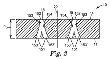
図1〜5は、本発明の代表的な燃料噴射ノズル10の様々な図を表す。図1に示されるように、代表的な燃料噴射ノズル10は、入口面11、入口面11と反対側の出口面14、内面154により画定される空洞153によって、出口面14の多数の開口部152と接続された入口面11の単一の入口開口部151を含む、少なくとも1つのノズル貫通孔15を含む。図2に示されるように、代表的な燃料噴射ノズル10は、入口面11、入口面11と反対側の出口面14、及び内面154により画定される空洞153により、出口面14の単一の出口開口部151と接続された入口面11の多数の入口開口部151を含む、少なくとも1つのノズル貫通孔15を含む。
1-5 represent various views of an exemplary
図1〜2に示されるように、代表的なノズル10のノズル貫通孔15は、空洞153に沿って延びる多数の空洞経路153’を含み、各空洞経路153’は、1つの出口開口部152に通じるか、又は1つの入口開口部151から延びる。
As shown in FIGS. 1-2, the nozzle through-
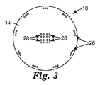
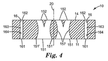
図3〜4に示されるように、本発明のノズル10は、1つ以上の配列28を含んでもよく、各配列28は、1つ以上のノズル貫通孔15、及び/又は1つ以上のノズル貫通孔16を含む。図4に示されるように、各ノズル貫通孔16は、入口面11に沿った単一の入口開口部161と、外面14に沿った単一の出口開口部162とを含む。
As shown in FIGS. 3-4, the
図5に示されるように、本発明の代表的なノズル10は更に、多数の任意の追加的な特徴を含み得る。任意の好適な特徴としては、追加的な特徴には、出口面14のいずれかの位置に沿って配置された1つ以上のコークス生成防止微細構造150、及び出口面14のいずれかの位置に沿った、1つ以上の流体衝突構造1519が挙げられるがこれらに限定されない。
As shown in FIG. 5, the
図1〜8Cに示されるように、本発明のノズル10は、ノズル貫通孔15及び16を含んでもよく、各ノズル貫通孔15/16は別個に以下の特徴を含む:(i)1つ以上の入口開口部151/161であって、それぞれがその別個の形状及び大きさを有する、開口部151/161と、(ii)それぞれが、その独自の形状及び大きさを有する、1つ以上の出口開口部152/163と、(iii)1つ以上の湾曲区分157、1つ以上の線形区分158、又は1つ以上の湾曲区分157及び1つ以上の線形区分158の組み合わせを含み得る、内面154/164の輪郭と、(iv)多数の入口開口部151から延びて、単一の出口開口部152へと延びる単一の空洞経路153’へと統合する、2つ以上の空洞経路153’、又は単一の入口開口部151から延び、多数の出口開口部152へと延びる2つ以上の空洞経路153’に分岐する、単一の空洞経路153’を含み得る、内面154の輪郭。各別個のノズル貫通孔15/16のこれらの特徴の選択は、ノズル10が、(1)各ノズル貫通孔15/16を通じた、実質的に同じ流体流(すなわち、ノズル貫通孔15それぞれの、多数の出口開口部152それぞれから、及び/又はノズル貫通孔16それぞれの、出口開口部162それぞれから出る、本質的に同じ流体流)と、(2)いずれか1つのノズル貫通孔15を通じた可変流体流(すなわち、所与のノズル貫通孔15の多数の出口開口部152から出る、同じではない流体流)、(3)いずれか2つ以上のノズル貫通孔15/16を通じた可変流体流(すなわち、所与のノズル貫通孔15の多数の出口開口部152、及び/又は各ノズル貫通孔16の各出口開口部162から出る、同じでない流体流)、(4)単一のノズル貫通孔15、多数のノズル貫通孔15、又はノズル貫通孔15/16のいずれかの組み合わせから出る、単一/多方向の流体流、(5)ノズル貫通孔15/16を出る線形及び/又は湾曲流体流、並びに(5)平行及び/又は分岐する、及び/又は平行でありその後分岐する、ノズル貫通孔15/16を出る流体流をもたらすことを可能にする。
As shown in FIGS. 1-8C, the
いくつかの実施形態において、ノズル貫通孔15/16の少なくとも1つが、入口開口部151/161の流れ軸、空洞153/163の流れ軸及び出口開口部152/162流れ軸を含み、少なくとも1つの流れ軸が、少なくとも1つの他の流れ軸とは異なる。本明細書において使用するとき、「流れ軸」は、燃料がノズル貫通孔15/16に入り、ここを流れ、ここから出る際の、燃料の流れの中央軸として定義される。多数の入口開口部151、多数の出口開口部152、又は両方を有する、ノズル貫通孔15の場合、ノズル貫通孔15は、多数の開口部151/152のそれぞれに対応する異なる流れ軸を有し得る。
In some embodiments, at least one of the nozzle through-
いくつかの実施形態において、入口開口部151/161流れ軸は、出口開口部152/162の流れ軸とは異なる場合がある。他の実施形態において、各入口開口部151/161の流れ軸、空洞153/163の流れ軸、及び出口開口部152/162の流れ軸は、互いに異なる。他の実施形態において、ノズル貫通孔15/16は、そこを流れる燃料が湾曲した流れ軸を有するように、動作可能に適合された(すなわち、そのような直径、構成、ないしは別の方法により設計される)空洞153/163を有する。
In some embodiments, the inlet opening 151/161 flow axis may be different from the flow axis of the
流れ軸のこのような違いを生じる要因の例としては、(1)(i)空洞153/163と(ii)入口面11及び/若しくは出口面14との間の異なる角度、(2)互いに位置合わせされておらず、平行でないか、異なる方向に沿って位置合わせされているか、平行であるが位置合わせされていないか、交差しているが位置合わせされていない、入口開口部151/161、及び/若しくは空洞153/163、及び/若しくは出口開口部152/162、並びに/又は(3)2つ以上の位置合わせされていない線形区分が取り得る、他の想到され得るいずれかの幾何学的関係性、のいずれかの組み合わせが挙げられるが、これらに限定されない。
Examples of factors that cause such differences in flow axes include (1) (i) different angles between the
開示されるノズル10は、開示されるノズルの特徴のいずれか1つ、又は開示されるノズルの特徴の2つ以上のいずれかの組み合わせを含み得る(又は本質的にこれらからなるか、又はこれらかなる)。加えて、図面に示されず、及び/又は本明細書において詳細に記載されないが、本発明のノズル10は以下の文献に開示される1つ以上のノズル特徴を更に含んでよく、これらの各主題及び開示内容は、本明細書において参照としてその全体を組み込まれる;(1)2012年8月1日に出願された、米国仮特許出願番号第61/678,475号(3M代理人整理番号第69909US002号、表題「GDI Fuel Injectors with Non−Coined Three−Dimensional Nozzle Outlet Face」)(例えば、出口面の重複する機構149)、(2)2012年8月1日に出願された、米国仮特許出願番号第61/678,356号(3M代理人整理番号第69910US002号、表題「Targeting of Fuel Output by Off−Axis Directing of Nozzle Output Streams」(例えば、燃料噴射器のサック容積を低減する、特定の開示されたノズル貫通孔15及び/又は入口面機構118)、(3)2012年8月1日に出願された、米国仮特許出願番号第61/678,305号(3M代理人整理番号第69912US002号、表題「Fuel Injectors with Improved Coefficient of Fuel Discharge」(例えば、比較的高い流量係数(COD)値を有する、特定の開示されたノズル貫通孔15)、及び(4)2012年8月1日に出願された、米国仮特許出願番号第61/678,288号(3M代理人整理番号第69913US002号、表題「Fuel Injectors with Non−Coined Three−dimensional Nozzle Inlet Face」(例えば、非圧印加工の三次元入口面11)。
The disclosed
本明細書において記載されるように、開示されるノズル10は、生じるノズル10が、内部に1つ以上のノズル貫通孔15を有する限り、いずれかの方法を使用して形成され得、少なくとも1つのノズル貫通孔15は、(i)入口面11に沿った単一の入口開口部151、及び出口面14に沿った多数の出口開口部152を有するか、又は(ii)入口面11に沿った多数の入口開口部151、及び出口面14に沿った単一の出口開口部152を有する。本発明のノズル10を作製する好適な方法は、国際特許出願番号第US2012/023624号に開示される方法に限定されないが、本発明のノズル10は、国際特許出願番号第US2012/023624号に開示される方法を使用して(例えば、二光子過程などの多光子過程を使用して)形成することができる。例えば、国際特許出願番号第US2012/023624の、図1A〜1M、及びその記載に示される方法工程を参照されたい。
As described herein, the disclosed
追加の実施形態
ノズルの実施形態
1.入口面11と、入口面11と反対側の出口面14と、少なくとも1つのノズル貫通孔15であって、(i)内面154によって画定される空洞153により上記出口面14の多数の出口開口部152と接続される、上記入口面11の単一の入口開口部151を含む、又は(ii)内面154により画定される空洞153により、上記外面14の単一の出口開口部151と接続される、上記入口面11の多数の入口開口部151を含む、少なくとも1つのノズル貫通孔15とを含む、燃料噴射ノズル10。
Additional Embodiments Nozzle Embodiments 1. An
2.上記少なくとも1つのノズル貫通孔15は、(i)、(ii)、又は(i)及び(ii)の両方を含む、複数のノズル貫通孔15である、実施形態1に記載のノズル10。
2. The
3.上記入口面11及び上記出口面14は、実質的に平行である、実施形態1又は2に記載のノズル10。
3. The
4.上記ノズル10は、実質的に平坦である、実施形態1〜3のいずれか1つに記載のノズル10。
4). The
5.上記ノズル貫通孔15それぞれの上記空洞153が、上記空洞153に沿って延びる多数の空洞経路153’を含み、各上記空洞経路153’が1つの上記出口開口部152に通じるか、又は1つの上記入口開口部151から延びる、実施形態1〜4のいずれか1つの記載のノズル10。
5. The
6.各上記ノズル貫通孔15の上記空洞153は、上記空洞153の最大全長Lの約10%以上(又は10%を超える、1.0%刻みの割合)に延びる、多数の空洞経路153’を含む、実施形態1〜5のいずれか1つに記載のノズル10。本明細書において使用するとき、用語「所与の空洞153の最大全長L」とは、所与の空洞153の入口開口部151から出口開口部152まで延びる最大距離を表す。例えば、図1に図示されるように、空洞153の長さは、ノズル10の湾曲表面部分157に沿って延びる。
6). The
7.上記多数の空洞経路153’は、上記空洞153の最大全長Lの約10%〜約90%(又は1.0%刻みの、その中間のいずれかの割合)だけ延びる、実施形態6に記載のノズル10。
7). The
8.上記ノズル貫通孔15それぞれの内部に、少なくとも4つの上記空洞経路153’が存在する、実施形態5〜7のいずれか1つに記載のノズル10。
8). The
9.上記ノズル貫通孔15それぞれの内部に、2〜50個の、又は1刻みのその中間のいずれかの数若しくは範囲(例えば、3〜20個)の上記空洞経路153’が存在する、実施形態5〜7のいずれか1つの記載のノズル10。
9. Embodiment 5 in which each of the nozzle through-
10.上記少なくとも1つのノズル貫通孔15は、1つの入口開口部151、及び多数の出口開口部152を含む、実施形態1〜9のいずれか1つに記載のノズル10。
10. 10. The
11.各上記空洞経路153’は、上記多数の出口開口部152の1つの上記出口開口部152に通じている、実施形態10に記載のノズル10。
11. The
12.上記少なくとも1つのノズル貫通孔15は、多数の入口開口部151、及び1つの出口開口部152を含む、実施形態1〜9のいずれか1つに記載のノズル10。
12 10. The
13.各上記空洞経路153’は、上記多数の出口開口部151の1つの上記入口開口部151に通じている、実施形態12に記載のノズル10。
13. 13. The
14.上記少なくとも1つのノズル貫通孔15は、多数の出口開口部152を含み、各上記空洞経路153’は1つの上記出口開口部152に通じ、これにより上記ノズル貫通孔15を通じて流れる流体(図示されない)は、(1)上記ノズル10の出口面14から所望の距離のおよその又は正確な位置において実質的に収束する(すなわち、いくつか、ほとんど、全て、ないしは少なくとも商業的に許容可能な数の流れが収束する)か、(2)上記ノズルの出口面から或る距離にわたり多数の別個の方向に実質的に分岐するか、(3)上記ノズル10の出口面から所望の距離にわたり実質的に平行なままであるか、(4)(1)、(2)及び(3)のいずれかの組み合わせの、多数の流体流を形成する、実施形態1〜11のいずれか1つに記載のノズル10。本明細書において使用するとき、用語「実質的に収束する」とは、互いに接触する隣接する流体流を指す。隣接する流体流の間の接触の度合いは様々であり得るが、最低でも隣接する流体流の経路は互いに重複する。本明細書において使用するとき、用語「実質的に分岐する」とは、互いに離れるように動く流体流を指す。図6に示される、空洞153を有するノズル貫通孔15は、最初に互いに平行であるが、最終的には出口開口部152から離れた位置である程度収束する、別個の流体流(図示されない)を生成する。対照的に、図7又は図8A〜8Cに示される、空洞153を有するノズル貫通孔は、流体が出口開口部152から出ると同時に互いに分岐し始める、5つの別個の流体流(図示されない)を生成する。
14 The at least one nozzle through-
各噴射器タイプ(すなわち、PFI、GDI、又はDI)における、燃料流れが分散すべき距離は、多くの要因に依存するべきである。例えば、PFIタイプの燃料噴射システムにおけるこのような距離に関し、ディレクタプレート(director plate)ポート間距離、これに加えて液体燃料の表面張力がこの距離に影響し得る。燃料流れが、ノズルからあまりに遠くで分散した場合、又は個別の流れ速度があまりに近い場合、液滴が形成されて燃料効率に悪影響を及ぼし得る。本発明により、例えば、ノズル貫通孔がより大きな入口開口部及びより小さな出口開口部を有するように、入口開口部面積の出口開口部面積に対する比率を変更することによって、個別の燃料流れ速度を実質的に異なるようにすることができる。 For each injector type (ie, PFI, GDI, or DI), the distance that the fuel flow should be distributed should depend on many factors. For example, for such distances in a PFI type fuel injection system, the distance between director plate ports, in addition to the surface tension of the liquid fuel, can affect this distance. If the fuel flow is dispersed too far from the nozzle, or if the individual flow velocities are too close, droplets can be formed and adversely affect fuel efficiency. In accordance with the present invention, individual fuel flow rates can be substantially increased, for example, by changing the ratio of inlet opening area to outlet opening area such that the nozzle through-hole has a larger inlet opening and a smaller outlet opening. Can be different.
ある点で収束し、衝撃により分散する個別の燃料流れを有することが目的である場合、このような点までの距離は、選択される内燃機関の詳細(直径、構成、及び設計)に依存する。PFI用途の一例において、燃焼室(すなわち、エンジンシリンダー)に空気を入れてこれがシリンダーに燃料の小さな液滴を搬入するように、燃料流れ又は噴霧が、吸込弁の直前で分散することが望ましい場合がある。小さい燃料の液滴ほど、空気の流路に従いやすく、よって弁の部分(例えば、背面)との接触を最小化することができる。燃料の噴霧が弁に接して分散することにより、内面にカーボン又はコークスが蓄積することがある。しかしながら、弁の背面を使用して、噴霧を分散させることが計画される場合、燃料噴射ノズルを出ると同時に、又はその直後に燃料の液滴を形成させることが望ましい場合がある。燃料の液滴の形成は、燃料噴霧が空気中を移動する際の、推進力の損失を最小化することができる。このように推進力の損失が低減することにより、燃料の液滴が吸込弁の背面に、より大きな推進力で衝突することとなり、これにより燃料流れ/噴霧が分散する度合いがより高いものとなり得る。 If the goal is to have individual fuel flows that converge at some point and disperse by impact, the distance to such points depends on the details (diameter, configuration and design) of the internal combustion engine selected . In an example of a PFI application, where it is desirable for the fuel flow or spray to disperse just before the intake valve so that air enters the combustion chamber (ie, the engine cylinder) and carries small droplets of fuel into the cylinder. There is. Smaller fuel droplets are more likely to follow the air flow path, thus minimizing contact with the valve portion (eg, backside). Carbon or coke may accumulate on the inner surface due to the spray of fuel being dispersed in contact with the valve. However, if it is planned to use the back of the valve to disperse the spray, it may be desirable to form fuel droplets at the same time as or after exiting the fuel injection nozzle. The formation of fuel droplets can minimize the loss of propulsion as the fuel spray travels through the air. This reduction in propulsion loss will cause fuel droplets to collide with the back of the suction valve with greater propulsive force, thereby increasing the degree of fuel flow / spray dispersion. .
15.上記空洞経路153’それぞれが、1つの上記出口開口部152に通じ、上記ノズル貫通孔15を流れる流体が、上記ノズル10の出口面14から所望の距離にわたって実質的に平行なままである、多数の流体流を形成する、実施形態14に記載のノズル10。
15. Each of the
16.上記流体流は、上記ノズル10の外面14に対して垂直な基準線20に沿って延びる、ノズル中央線と実質的に平行である、実施形態15に記載のノズル10。
16. The
17.上記空洞経路153’それぞれが、1つの上記出口開口部152に通じ、上記ノズル貫通孔15を流れる流体が、上記ノズル10の出口面14から所望の距離にある位置周辺で実質的に収束する、多数の流体流を形成する、実施形態14に記載のノズル10。
17. Each of the
18.上記空洞経路153’それぞれが1つの上記出口開口部152に通じ、上記ノズル貫通孔15を流れる流体が、多数の別個の方向に実質的に分岐する多数の流体流を形成する、実施形態14に記載のノズル10。
18. In
19.上記流体流は、上記ノズル10の外面14に対して垂直な基準線に沿って延びる、ノズル中央線20に対して実質的に軸外にある、実施形態17又は18に記載のノズル10。
19. 19. The
20.上記空洞経路153’はそれぞれ、1つの上記出口開口部152に通じ、上記ノズル貫通孔15を流れる流体は、(1)上記ノズル10の出口面14から離れた位置において実質的に収束し、(2)上記ノズルの出口面から或る距離にわたり多数の別個の方向で実質的に分岐し、(3)上記ノズル10の出口面14から所望の距離にわたり実質的に平行なままである、多数の流体流を形成する、実施形態14に記載のノズル10。
20. Each of the
21.上記流体流は、上記ノズル10の外面14に対して垂直な基準線に沿って延びる、ノズル中央軸20に対して軸外の線と実質的に平行な流れを含む、実施形態20に記載のノズル10。
21. 21. The embodiment of
22.上記空洞経路153’はそれぞれ、1つの上記出口開口部152に続き、上記少なくとも1つのノズル貫通孔15を流れる流体が、上記ノズル10の出口面14から所望の距離にある2つ以上の別個の位置に向かう流体流を形成する、実施形態1〜21のいずれか1つに記載のノズル10。
22. Each of the
ノズル出口面から出る際の、燃料流れの分散の典型的な距離

*−経路の後に、多数のノズル貫通孔、単一のノズル貫通孔の多数の出口開口部、又はその両方により形成される、多数の燃料流れが続くことを指す。
Typical distance of fuel flow dispersion as it exits the nozzle exit face
* -Refers to a path followed by a number of fuel flows formed by a number of nozzle through holes, a number of outlet openings of a single nozzle through hole, or both.
23.距離は、約10mm〜約400mm(又は1.0mm刻みのその中間のいずれかの数若しくは範囲)である、実施形態14〜17、及び19〜21のいずれか1つに記載のノズル10。
23. The
24.距離は、約0.01mm〜約400mm(又は0.01mm刻みのその中間のいずれかの数若しくは範囲)である、実施形態14〜17、及び19〜21のいずれか1つに記載のノズル10。
24. The
25.距離は、約10mm〜約250mm(又は0.01mm刻みの、約0.01mm〜250mm内のいずれかの数又は範囲)である、実施形態14、18〜20、及び22のいずれか1つに記載のノズル10。
25. In any one of
26.上記少なくとも1つのノズル貫通孔15は、複数のノズル貫通孔15である、実施形態1〜25のいずれか1つに記載のノズル10。
26. The
27.上記入口面11から上記出口面14まで流体を方向付けるための、ノズル貫通孔15の1つ以上の配列28を更に含み、上記1つ以上の配列28の少なくとも1つが、上記少なくとも1つのノズル貫通孔15を含む、実施形態1〜26のいずれか1つに記載のノズル10。
27. It further includes one or
28.1つ以上の追加的なノズル貫通孔16を更に含み、各追加的なノズル貫通孔16は、内面164により画定される空洞163により、上記出口面14の単一の出口開口部162と接続された、上記入口面11の単一の入口開口部161を含む、実施形態1〜27のいずれか1つに記載のノズル10。
28. Further includes one or more additional nozzle through-
29.少なくとも1つの上記ノズル貫通孔15/16は、入口開口部151/161から出口開口部152/162まで直接延びる方向に沿って湾曲した、少なくとも1つの湾曲部157を備える、内面154/164を含む、湾曲ノズル貫通孔15/16である、実施形態1〜28のいずれか1つに記載のノズル10。本明細書において記載するとき、湾曲部157、線形部158、及び/又は他のいずれかの表面部分が、少なくとも1つの入口開口部151から少なくとも2つの出口開口部152まで直接延びる、内面154の「湾曲した表面輪郭」の前部又は一部を形成する。「湾曲した表面輪郭」とは、(i)少なくとも1つの開口部151から少なくとも1つの出口開口部152まで直接延びる内面154に沿った最短距離、(ii)少なくとも1つの入口開口部151から少なくとも1つの出口開口部152まで直接延びる、内面154に沿った最長距離、又は(iii)少なくとも1つの入口開口部151から少なくとも1つの出口開口部152まで直接延びる内面154に沿った、その中間の他のいずれかの距離を指す場合がある。
29. The at least one nozzle through-
30.上記湾曲区分157は、入口開口部151/161の付近から始まる、上記湾曲したノズル貫通孔15/16の内面154/164に沿って直接延びる(すなわち、少なくとも1つの入口開口部151から少なくとも1つの出口開口部152まで直接延びる)、実施形態29に記載のノズル10。
30. The
31.上記湾曲区分157は、少なくとも1つの出口開口部152/162まで延びる(すなわち、少なくとも1つの出口開口部151から少なくとも1つの出口開口部152まで直接延びる)、実施形態30のノズル10。
31. The
32.上記湾曲したノズル貫通孔15/16の内面154/164は、上記内面154/164の、上記湾曲部分157と反対側に湾曲していない線形部分158を含み、上記線形部分158は入口開口部151/161から出口開口部152/162まで直接延びる方向に沿って非湾曲である、実施形態29〜31に記載のいずれか1つに記載のノズル10。
32. The
33.上記線形部分158が、上記ノズル10の入口面11の一部と鈍角Aを画定する、実施形態32に記載のノズル10。
33. The
34.上記線形部分158は、少なくとも1つの出口開口部152/162まで延びる、実施形態32又は33に記載のノズル10。
34. 34. The
35.上記湾曲したノズル貫通孔15/16の内面154/164が、入口開口部151/161から出口開口部152/162まで直接延びる方向に沿って湾曲する、別の湾曲部分157’を含み、上記他の湾曲部分157’は、入口開口部151/161の付近から始まって、上記線形部分158が始まる場所で終わっている、実施形態32〜34のいずれか1つに記載のノズル10。
35. The
36.上記他の湾曲した部分157’は凸状である、実施形態35に記載のノズル10。
36. 36. The
37.上記湾曲したノズル貫通孔15/16の内面154/164の上記少なくとも1つの湾曲部分157が、上記湾曲したノズル貫通孔15/16の空洞153/163の両側に2つの湾曲部分157/157’を含む(すなわち、それぞれが少なくとも1つの入口開口部151から少なくとも1つの出口開口部152の方向に直接延びる)、実施形態29〜36のいずれか1つに記載のノズル10。
37. The at least one
38.上記2つの湾曲部分157/157’の一方が凸状の形状を有し、上記2つの湾曲部分157/157’の他方が凹状の形状を有する(すなわち、それぞれが、少なくとも1つの入口開口部151から少なくとも1つの出口開口部152の方向に直接延びる)、実施形態37に記載のノズル10。
38. One of the two
39.上記2つの湾曲部分157/157’の一方が第1の凸状の形状を有し、上記2つの湾曲部分157/157’の他方が第2の凸状の形状を有する(すなわち、それぞれが、少なくとも1つの入口開口部151から少なくとも1つの出口開口部152の方向に直接延びる)、実施形態37に記載のノズル。
39. One of the two
40.上記湾曲したノズル貫通孔15/16の上記入口開口部151/161が、上記湾曲したノズル貫通孔15/16の内面154/164の凸状の湾曲部分により画定された、外辺部151’/161’を有する、実施形態29〜39のいずれか1つに記載のノズル10。
40. The
41.(a)少なくとも1つのノズル貫通孔15の上記入口開口部151、又は上記多数の入口開口部151は、上記入口面11に沿って入口開口部パターンを形成し、上記入口開口部パターンは入口開口部外辺部、及び入口開口部外辺部直径idを有し、(b)少なくとも1つのノズル貫通孔15の上記多数の出口開口部152又は上記出口開口部152が、上記出口面14に沿って出口開口部パターンを形成し、上記出口開口部パターンは、出口開口部外辺部、及び出口開口部外辺部直径odを有し、(i)上記全体的な入口開口部外辺部直径id、(ii)上記全体的な出口開口部外辺部直径od、又は(iii)上記全体的な入口開口部外辺部直径id及び上記全体的な出口開口部外辺部直径odの両方が別個に、少なくとも1つのノズル貫通孔15の上記空洞153の少なくとも一部に沿った、空洞直径cdよりも大きい、実施形態1〜40のいずれか1つに記載のノズル10。
41. (A) The
42.(a)上記入口開口部151又は上記多数の入口開口部151が、上記入口面11に沿って入口開口部パターンを形成し、上記入口開口部パターンは、入口開口部外辺部及び入口開口部外辺部直径idを有し、(b)上記多数の出口開口部152又は上記出口開口部152は、上記出口面14に沿って出口開口部パターンを形成し、上記出口開口部パターンは、出口開口部外辺部及び出口開口部外辺部直径odを有し、上記出口開口部外辺部直径odは個別に、上記空洞部153の少なくとも一部に沿った空洞直径cdよりも大きい、実施形態1〜41のいずれか1つに記載のノズル10。
42. (A) The
43.(a)上記入口開口部151又は上記多数の入口開口部151が、上記入口面11に沿って入口開口部パターンを形成し、上記入口開口部パターンは、入口開口部外辺部及び入口開口部外辺部直径idを有し、(b)上記多数の出口開口部152、又は上記出口開口部152は、上記出口面14に沿って出口開口部パターンを形成し、上記出口開口部パターンは、出口開口部外辺部、及び出口開口部外辺部直径odを有し、(i)上記全体的な出口開口部外辺部直径id、及び(ii)上記全体的な出口開口部外辺部直径odは、上記空洞153の少なくとも一部に沿った空洞直径cdよりも大きい、実施形態1〜42のいずれか1つに記載のノズル10。
43. (A) The
44.上記空洞経路153’は、上記空洞経路153’が上記ノズル10を通じて回転する際に、x−y平面内で回転する、実施形態5〜43のいずれか1つに記載のノズル10。例えば、図7に示される空洞153内の回転する空洞経路153’を参照されたい。
44. 44. The
45.少なくとも1つのノズル貫通孔15の、少なくとも1つの入口開口部151、及び少なくとも1つの出口開口部152が、同様の形状を有する、実施形態1〜44のいずれか1つに記載のノズル10。多数の入口開口部151又は多数の出口開口部152を備える、所与のノズル貫通孔15は、異なる開口部直径及び/又は開口部形状を有する、2つ以上の入口開口部151、又は2つ以上の出口開口部152を含み得ることが理解されるべきである。このような開口部の構成は、単一のノズル貫通孔15とは異なる流体速度、及び液滴の寸法を有する、個別の流体流を生成する。
45. 45. The
46.少なくとも1つのノズル貫通孔15の、少なくとも1つの入口開口部151、及び少なくとも1つの出口開口部152が、異なる形状を有する、実施形態1〜45のいずれか1つに記載のノズル10。
46. 46. The
47.各ノズル貫通孔15/16は、合計入口開口部面積、及び合計出口開口部面積を有し、上記合計入口開口部面積は、上記合計出口開口部面積よりも大きい、実施形態1〜46のいずれか1つに記載のノズル10。
47. Each nozzle through-
48.上記ノズル10の、合計入口開口部面積の、合計出口開口部面積への全体的な比率が、1.0超〜約250の範囲(又は0.1刻みのその中間のいずれかの数、若しくは範囲)である、実施形態1〜47のいずれか1つに記載のノズル10。
48. The overall ratio of the total inlet opening area of the
49.上記ノズル10の、全体的な入口開口部面積の全体的な出口開口部面積に対する全体的な比率が、約0.0025(例えば1:400)〜約400(例えば、400:1)(0.0025刻みのその中間のいずれかの比率又は比率の範囲(小数により示される比率)、又は1:1(個々の値による比))、実施形態1〜47のいずれか1つに記載のノズル10。
49. The overall ratio of the overall inlet opening area of the
50.上記ノズル10は、上記出口面14に沿って延びる、1つ以上の出口表面機構150/1519を更に含む、実施形態1〜49のいずれか1つに記載のノズル10。出口面14に沿って延びる出口表面機構150/1519としては、図5に示されるコークス生成防止微細構造150、図5に示される流体衝突部材1519、又はこれらの組み合わせが挙げられるがこれらに限定されない。本発明のノズル10に使用するための他の好適な出口表面機構としては、上記の米国仮特許出願番号第61/678,475号(3M代理人整理番号第69909US002号、表題「GDI Fuel Injectors with Non−Coined Three−Dimensional Nozzle Outlet Face」)に開示される、重複する出口面構造149が挙げられるがこれらに限定されない。
50. 50. The
51.上記1つ以上の出口表面機構1519は、上記外面14に沿って位置づけられた、1つ以上の流体衝突部材1519を含む、実施形態50に記載のノズル10。
51. 51. The
52.各入口開口部151/161は、約400マイクロメートル未満の直径(又は約300マイクロメートル未満、又は約200マイクロメートル未満、又は約160マイクロメートル未満、又は約100マイクロメートル未満)(1.0マイクロメートル刻みで、約10マイクロメートル〜400マイクロメートルのいずれかの直径、例えば、10、11、12マイクロメートル等)を有する、実施形態1〜51のいずれか1つに記載のノズル10。本明細書において使用するとき、用語「直径」は、入口開口部151/161(又は出口開口部152/162)にわたる、最大距離を記載するために使用される。
52. Each inlet opening 151/161 has a diameter of less than about 400 micrometers (or less than about 300 micrometers, or less than about 200 micrometers, or less than about 160 micrometers, or less than about 100 micrometers) (1.0 micrometers). 52. The
53.各出口開口部152/162は、約400マイクロメートル未満の直径(又は約300マイクロメートル未満、又は約200マイクロメートル未満、又は約100マイクロメートル未満、又は約50マイクロメートル未満、又は約20マイクロメートル未満)(又は1.0マイクロメートル刻みの、約10マイクロメートル〜400マイクロメートルのいずれかの直径、例えば、10、11、12マイクロメートル等)を有する、実施形態1〜52のいずれか1つに記載のノズル10。
53. Each outlet opening 152/162 has a diameter less than about 400 micrometers (or less than about 300 micrometers, or less than about 200 micrometers, or less than about 100 micrometers, or less than about 50 micrometers, or about 20 micrometers). Any one of embodiments 1 to 52 (or less than about 10 micrometers to 400 micrometers in diameter, such as 10, 11, 12 micrometers, etc.)
54.ノズル10が、金属材料、無機非金属材料(例えば、セラミック)、又はこれらの組み合わせを含む、実施形態1〜53のいずれか1つに記載のノズル10。
54. 54. The
55.ノズル10が、シリカ、ジルコニア、アルミナ、チタニア、又は、イットリウム、ストロンチウム、バリウム、ハフニウム、ニオビウム、タンタル、タングステン、ビスマス、モリブデン、スズ、亜鉛、57〜71の範囲の原子番号を有するランタニド元素、セリウム、及びそれらの組合せの酸化物からなる群から選択されるセラミックを含む、実施形態1〜54のいずれか1つに記載のノズル10。
55.
燃料噴射器実施形態
56.実施形態1〜55のいずれか1つに記載のノズル10を含む燃料噴射器101。
Fuel injector embodiment 56. A
燃料噴射システム実施形態
57.実施形態56の燃料噴射器101を含む車両200の燃料噴射システム100。図9に示されるように、代表的な燃料噴射システム100はとりわけ、燃料噴射器101、燃料源/タンク104、燃料ポンプ103、燃料フィルター102、燃料噴射電源105、及び内燃機関106を含み得る。
Fuel injection system embodiment 57. 57. A
58.2つ以上の燃料成分リザーバ104a/104b、及び各燃料成分リザーバ104a/104bと上記ノズル10の上記入口面11に沿った容積との間に延びる管108a/108bを更に含み、上記少なくとも1つのノズル貫通孔15は、燃料成分がノズル10を移動する際に、上記2つ以上の燃料成分リザーバ104a/104bからの2つ以上の燃料成分(図示されない)を混合するために、多数の入口151a/151b、及び単一の出口152を含む、実施形態57に記載の燃料噴射システム100。図10に示されるように、2つ以上の燃料成分リザーバ104a/104b、及び管108a/108bに加えて、代表的な燃料噴射システム100は更に、とりわけ、燃料噴射器101、燃料成分ポンプ104a/104b、燃料成分フィルター102a/102b、燃料噴射源105、及び内燃機関106を含み得る。
58. further comprising two or more
ノズル実施形態を作製する方法
59.実施形態1〜55のいずれか1つに記載のノズル10を作製する方法。
Method of making the nozzle embodiment 59. The method for producing the
60.燃料噴射ノズル10を作製する方法であって、上記方法が:
燃料噴射ノズル10内の少なくとも1つのノズル貫通孔15を形成する工程であって、少なくとも1つのノズル貫通孔15は、入口面11から、ノズル10の入口面11の反対の出口面14まで延びる、工程を含み、少なくとも1つのノズル貫通孔15は、(i)内面154によって画定された空洞152により、出口面14上の多数の出口開口部152と接続された、入口面11上の単一の入口開口部151、又は(ii)内面154により画定される空洞153により、出口面14上の単一の出口開口部152と接続された、入口面11上の多数の入口開口部151を含む、方法。
60. A method of making a
Forming at least one nozzle through
61.上記形成工程が、1つ以上のノズル孔形成機構を含むノズル形成微細構造化パターンの上にノズル形成材料を適用する工程と、ノズル形成微細構造化パターンからノズル形成材料を分離してノズル10をもたらす工程と、必要に応じてノズル10から材料を除去して少なくとも1つのノズル貫通孔15を形成する工程とを含む、実施形態60に記載の方法。例えば、国際特許出願番号第US2012/023624の、図1A〜1M、及びその記載に示される方法工程を参照されたい。
61. The forming step includes applying a nozzle forming material on a nozzle forming microstructured pattern including one or more nozzle hole forming mechanisms; separating the nozzle forming material from the nozzle forming microstructured pattern; 61. The method of embodiment 60 comprising the steps of providing and removing material from the
62.ノズル形成微細構造パターンは更に、1つ以上の平坦な基準空洞形成機構を含む、実施形態61に記載の方法。 62. 62. The method of embodiment 61, wherein the nozzle forming microstructure pattern further comprises one or more flat reference cavity forming features.
63.上記形成工程は更に、成形型の少なくとも一部を画定し、少なくとも1つの複製ノズル孔を含む、微細構造化成形パターンをもたらす工程と、ノズル形成微細構造化パターンを形成するために微細構造化成形パターンに第1材料を成形する工程とを更に含む、実施形態61又は62に記載の方法。 63. The forming step further includes providing a microstructured forming pattern defining at least a portion of the mold and including at least one replicated nozzle hole; and microstructured forming to form the nozzle forming microstructured pattern. 63. The method of embodiment 61 or 62, further comprising forming a first material into the pattern.
64.微細構造化成形型パターンが、少なくとも1つの複製ノズル穴を(a)少なくとも1つの他の複製ノズル穴、(b)上記微細構造化成形型パターンの外辺部を超えた成形型の部分、又は(c)(a)及び(b)の両方に連結させる、少なくとも1つの流体チャネル機構を含む、実施形態63に記載の方法。 64. The microstructured mold pattern has at least one replication nozzle hole (a) at least one other replication nozzle hole, (b) a portion of the mold beyond the outer edge of the microstructured mold pattern, or 64. The method of embodiment 63, comprising (c) at least one fluid channel mechanism coupled to both (a) and (b).
65.第1材料が、ある度合いの弾性を有する材料を含む、実施形態63又は64に記載の方法。 65. The method of embodiment 63 or 64, wherein the first material comprises a material having a degree of elasticity.
66.第1材料が、ポリプロピレン又はポリカーボネートを含む、実施形態63〜65のいずれか1つに記載の方法。多くの成形可能なポリマーのいずれかが、第1材料として使用され得ることに留意すべきである。好適な成形可能なポリマーとして、ポリカーボネート、液晶ポリマー(LCP)、ポリエーテルエーテルケトン(PEEK)、ポリプロピレン(PP)、熱可塑性ウレタン(TPU)などの熱可塑性エラストマー(TPE)、フルオロポリマー、ポリマーにより封入された金属粒子(例えば、金属射出成形(MIM)において使用され、先に記載されるもの)が挙げられるがこれらに限定されない。 66. The method according to any one of embodiments 63-65, wherein the first material comprises polypropylene or polycarbonate. It should be noted that any of a number of moldable polymers can be used as the first material. Suitable moldable polymers include polycarbonate, liquid crystal polymer (LCP), polyetheretherketone (PEEK), polypropylene (PP), thermoplastic elastomer (TPE) such as thermoplastic urethane (TPU), fluoropolymer, encapsulated by polymer Metal particles (eg, those used in metal injection molding (MIM) and described above), but are not limited to these.
67.少なくとも1つのノズル貫通孔15が、複数のノズル貫通孔15を含む、実施形態60〜66のいずれか1つに記載の方法。
67. Embodiment 67. The method of any one of embodiments 60 through 66, wherein the at least one nozzle through
68.上記形成工程は更に、流体噴射ノズル10内に1つ以上の追加的なノズル貫通孔16を形成する工程であって、各追加的なノズル貫通孔16は出口面11からノズル10の出口面14まで延びる、工程を含み、各追加的なノズル貫通孔は(i)内面164により画定される空洞163により、出口面14の単一の出口開口部162と接続された、入口面11の単一の入口開口部161を含む、実施形態60〜67のいずれか1つに記載の方法。
68. The forming step further includes forming one or more additional nozzle through
燃料噴射器実施形態を作製する方法
69.上記方法は、実施形態1〜55のいずれか1つのノズル10を、燃料噴射器101内に導入する工程を含む、燃料噴射器101を作製する方法。
Method of making a fuel injector embodiment 69. The said method is a method of producing the
燃料噴射システム実施形態を作製する方法
70.車両200の燃料噴射システム100を作製する方法であって、上記方法は、実施形態69の燃料噴射器101を、燃料噴射システム100に導入する工程を含む、車両200の燃料噴射システム100を作製する方法。
Method of making a fuel injection system embodiment 70. A method for producing a
71.燃料噴射システム100が、シリンダー1063ごとに2つの吸込弁1062を含み、少なくとも1つのノズル貫通孔15が別個に流体1064を、2つの吸込弁1062に向けて、分割吸込マニホールド1065の対応するスロート部へと下方に向ける、実施形態70に記載の方法。図11に示されるように、代表的な燃料噴射システム100はとりわけ、燃料噴射器101、燃料源/タンク104、燃料ポンプ103、燃料フィルター102、燃料噴射電源105、及び内燃機関106を含み得る。内燃機関106は更に、燃焼チャンバ1061を含む。
71. The
燃料噴射システム実施形態を使用する方法
72.上記方法が、各燃料成分が別個に、単一のノズル貫通孔15の別個の入口開口部151から入り、単一のノズル貫通孔15の単一の出口開口部152から出るように、2種類以上の燃料成分(図示されない)を燃料噴射システム100に導入し、燃料成分がノズル10を通じて移動する際に、2つ以上の燃料リザーバ104a/104bからの2種類以上の燃料成分を、混合する工程を含む、実施形態58の燃料噴射システム100を使用する方法。
Method of using a fuel injection system embodiment 72. There are two ways in which the above method allows each fuel component to enter separately from a separate inlet opening 151 of a single nozzle through
ノズルプリフォームの実施形態
73.実施形態1〜55のいずれか1つに記載のノズル10を形成するのに好適なノズルプリフォーム。例えば、国際特許出願番号第US2012/023624号の、図1A〜1M、及びその記載における、他のノズルプリフォーム、及びノズルを形成するためにノズルプリフォームを使用する方法を参照されたい。
Embodiment of nozzle preform 73. A nozzle preform suitable for forming the
微細構造化パターンの実施形態
74.実施形態1〜55のいずれか1つに記載のノズル10を形成するために好適な微細構造化パターン。例えば、国際特許出願番号第US2012/023624号の、図1A〜1M、及びその記載における、他のノズルプリフォーム、及びノズルを形成するためにノズルプリフォームを使用する方法を参照されたい。
Embodiment of microstructured pattern 74. A microstructured pattern suitable for forming the
上記の実施形態のいくつかにおいて、ノズル10は実質的に平坦な構成を有するノズルプレート10を含んでもよく、典型的には入口面11の少なくとも一部が出口面14の少なくとも一部と実質的に平行である。
In some of the above embodiments, the
望ましくは、本発明のノズル10はそれぞれ、別個にモノリシックの構成を含む。本明細書において使用するとき、「モノリシック」とは、ノズルを形成するために互いに組み合わせられる、多数の部品又は構成要素ではなく、単一の一体的に形成された構造を有するノズルを指す。
Desirably, each
燃料噴射ノズル10の厚さが少なくとも約100μm、好ましくは約200μmよりも大きく、約3mmより小さく、好ましくは約1mmより小さく、より好ましくは、約500μmより小さい(又は1.0μm刻みの、約100μm〜約3mmの間のいずれかの厚さ)ことが望ましい場合がある。
The thickness of the
更に、図面には示されないが、本明細書において記載されるノズル10のいずれかが、(1)燃料噴射101に対するノズル10の位置合わせ(すなわち、x−y平面)、及び(2)燃料噴射器101に対するノズル10の回転による位置合わせ/方向付け(すなわち、x−y平面内における適切な回転位置)を可能にする、1つ以上の位置合わせ表面機構を更に含み得る。上記のように、1つ以上の位置合わせ表面機構は、1つ以上の標的位置ltに正確かつ精密に方向付けるように、ノズル10及びノズル貫通孔15を内部に配置するのを補助する。ノズル10上の1つ以上の位置合わせ表面機構は、入口面11、出口面14、外辺部19、又は入口面11、出口面14、及び外辺部19のいずれかの組み合わせに沿って存在し得る。更に、ノズル10上の1つ以上の位置合わせ表面機構は、視覚的マーキング、ノズル10内のくぼみ、ノズル10に沿った隆起表面部、又はこのような位置合わせ表面機構のいずれかの組み合わせを含み得るが、これらに限定されない。
In addition, although not shown in the drawings, any of the
上記のノズル、ノズルプレート、燃料噴射器、燃料噴射システム、及び方法は、1つ以上の構成要素、特徴、又は工程を「含む」ものとして記載されるが、上記のノズル、ノズルプレート、燃料噴射器、燃料噴射システム、及び方法が、ノズル、ノズルプレート、燃料噴射器、燃料噴射システム、及び方法の上記の構成要素、及び/又は特徴、及び/又は工程のいずれかを「含み」、「これからなり」、又は「これから本質的になり」得るものと理解されるべきである。結果として、本発明又はその一部が、「含む」などのオープンエンドタームで記載された場合、本発明の記載、又はその一部はまた(他に明言されない場合)、用語「〜から本質的になる」、又は「〜からなる」、又は下記のこれらの変化形を使用して、本発明、又はその一部を記載するものと解釈されるべきであることが、容易に理解されるはずである。 Although the nozzle, nozzle plate, fuel injector, fuel injection system, and method described above are described as “comprising” one or more components, features, or steps, the nozzle, nozzle plate, fuel injection described above , The fuel injection system, and the method "include", "from now on" any of the above components, and / or features, and / or steps of the nozzle, nozzle plate, fuel injector, fuel injection system, and method It should be understood that it can be “being” or “becoming essentially”. As a result, if the present invention or a portion thereof is described in an open-ended term such as “including”, the description of the present invention, or a portion thereof, also (unless otherwise stated) is essentially It should be readily understood that it should be construed as describing the invention, or portions thereof, using “being” or “consisting of” or using these variations below. It is.
本明細書において使用するとき、用語「含む(comprises)」、「含む(comprising)」、「含む(includes)」、「含む(including)」、「有する(has)」、「有する(having)」、「含有する(contains)」、「含有する(containing)」、「〜により特徴付けられる」、又はこれらの他のいずれかの変化形は、別に明示的に示されるいずれかの制限に従いながら、言及される構成要素の、非排他的包含を包括するものと解釈される。¥ 例えば、要素のリスト(例えば、構成要素、又は特徴、又は工程)を「含む」、ノズル、ノズルプレート、燃料噴射器、燃料噴射システム、及び/又は方法は、これらの要素(又は構成要素、特徴、又は工程)に必ずしも制限されず、明示的に掲示されていない、又はノズル、ノズルプレート、燃料噴射器、燃料噴射システム、及び/若しくは方法に固有の他の要素(又は構成要素、特徴、又は工程)を含み得る。 As used herein, the terms “comprises”, “comprising”, “includes”, “including”, “has”, “having” , "Contains", "containing", "characterized by", or any other variation thereof, subject to any other explicitly indicated limitations, It is to be interpreted as encompassing non-exclusive inclusion of the referenced component. $ For example, “include” a list of elements (eg, a component, or a feature or process), a nozzle, a nozzle plate, a fuel injector, a fuel injection system, and / or a method, these elements (or components, Other elements (or components, features) that are not necessarily limited to, are not explicitly posted, or that are specific to the nozzle, nozzle plate, fuel injector, fuel injection system, and / or method. Or a step).
本明細書において使用するとき、移行句「〜からなる(consistsof)」及び「〜からなる(consisting of)」は、指定されていないあらゆる要素、工程、又は構成要素をも排除する。例えば、請求項において使用される「〜からなる(consists of)」又は「〜からなる(consisting of)」は、請求項を、通常伴われる不純物(すなわち、所与の構成要素内の不純物)を除き、請求項で特に言及される成分、材料、又は工程に限定する。用語「〜からなる(consists of)」、又は「〜からなる(consisting of)」が、序文の直後ではなく、請求項の本文の節の中に用いられるとき、用語「〜からなる(consists of)」、又は「〜からなる(consisting of)」は、その節において記載される要素(又は構成要素若しくは工程)のみを限定し、他の要素(又は構成要素)がその請求項全体から除外されることはない。 As used herein, the transitional phrases “consists of” and “consisting of” exclude any element, step, or component not specified. For example, “consists of” or “consisting of” as used in the claims refers to the impurities that are normally accompanied by the claim (ie, impurities within a given component). Except as limited to the components, materials, or steps specifically recited in the claims. When the term “consists of” or “consisting of” is used in the main text section of a claim rather than immediately after the introduction, the term “consists of” Or “consisting of” limits only the elements (or components or steps) described in that section and excludes other elements (or components) from the entire claim. Never happen.
本明細書において使用するとき、「〜からなる(consistsof)」、又は「〜からなる(consisting of)」は、文言上明示的に開示されているものに加えて、材料、工程、特徴、構成要素、又は要素を含む、ノズル、ノズルプレート、燃料噴射器、燃料噴射システム、及び/又は方法を定義するために使用されるがただし、これらの追加的な材料、工程、特徴、構成要素、又は要素は、請求される発明の基本的かつ新規の特徴に重大な影響を与えることはない。用語「〜から本質的になる(consisting essentially of)」は、「〜を含む(comprising)」と「〜からなる(consisting of)」との中間を指す。 As used herein, “consistsof” or “consisting of” includes materials, processes, features, configurations in addition to those explicitly disclosed in the language. Used to define an element, or nozzle, nozzle plate, fuel injector, fuel injection system, and / or method that includes an element, provided that these additional materials, steps, features, components, or Elements do not have a significant impact on the basic and novel features of the claimed invention. The term “consisting essentially of” refers to an intermediate between “comprising” and “consisting of”.
更に、本明細書において開示されるノズル、ノズルプレート、燃料噴射器、燃料噴射システム、及び/又は方法は、図面に示されないいずれかの追加の特徴を含み、又は含まずに、図に示される、本明細書に記載される構成要素及び特徴のいずれかを含む、これから本質的になる、又はこれからなることがあるものと、理解されるべきである。換言すると、いくつかの実施形態において、本発明のノズル、ノズルプレート、燃料噴射器、燃料噴射システム、及び/又は方法は、図に具体的に示されないいずれかの追加的な特徴を有し得る。いくつかの実施形態において、本発明のノズル、ノズルプレート、燃料噴射器、燃料噴射システム、及び/又は方法は、図面に示されるもの(すなわち、一部又は全部)以外のいずれの追加的な特徴も有さず、そしてこのような図面に示されない追加的な特徴は、ノズル、ノズルプレート、燃料噴射器、燃料噴射システム、及び/又は方法から排除される。 Further, the nozzles, nozzle plates, fuel injectors, fuel injection systems, and / or methods disclosed herein are shown in the figures, with or without any additional features not shown in the drawings. It should be understood that it comprises, consists essentially of, or may consist of any of the components and features described herein. In other words, in some embodiments, the nozzles, nozzle plates, fuel injectors, fuel injection systems, and / or methods of the present invention may have any additional features not specifically shown in the figures. . In some embodiments, the nozzles, nozzle plates, fuel injectors, fuel injection systems, and / or methods of the present invention are any additional features other than those shown in the drawings (ie, some or all). And additional features not shown in such drawings are excluded from the nozzle, nozzle plate, fuel injector, fuel injection system, and / or method.
本発明は、以下の例によって更に例示されるが、それらの範囲によっていかなる意味でも限定されると解すべきではない。逆に本明細書の説明を読むことで、本発明の趣旨及び/又は添付の特許請求の範囲から逸脱することなく当業者にそれ自体を示唆し得る様々な他の実施形態、改変及びその均等物が考えられることは明確に理解されるはずである。 The present invention is further illustrated by the following examples, but should not be construed as limited in any way by their scope. Conversely, upon reading the description herein, various other embodiments, modifications and equivalents thereof may be suggested to those skilled in the art without departing from the spirit of the invention and / or the appended claims. It should be clearly understood that things are possible.
(実施例1)
ノズルプレートの調製は、従来的なコンピュータ援用設計ソフトウェア(CAD)を使用して、その貫通孔を設計することから始まる。意図される設計の図面が用意され、図面中、個別の貫通孔が一端に単一の孔又は開口部を、他端に4つの別個の孔又は開口部を有する。2つの端部の間における断面の分割(すなわち、1つの空洞が4つの分割される)は、厚さ全体のおよそ70%にわたって生じる。実施例1のノズルプレートにおいて使用される貫通孔の設計は、図6に示される。
Example 1
Nozzle plate preparation begins with designing the through-hole using conventional computer aided design software (CAD). A drawing of the intended design is provided, in which the individual through-holes have a single hole or opening at one end and four separate holes or openings at the other end. The division of the cross section between the two ends (ie, one cavity is divided into four) occurs over approximately 70% of the total thickness. The design of the through hole used in the nozzle plate of Example 1 is shown in FIG.
この実施例のノズルプレートは、CAD設計ソフトウェアを使用して、上記の貫通孔の配列として設計され、中央に位置する貫通孔が、その周囲の同心円上に構成された追加的な貫通孔により包囲され、典型的な二次元の六角形の充填規則で37個の貫通孔を形成するようにする。 The nozzle plate of this example is designed as an array of the above-described through holes using CAD design software, and the centrally located through hole is surrounded by an additional through hole configured on a concentric circle around it. 37 through holes are formed by a typical two-dimensional hexagonal filling rule.
ノズルプレート配列内における貫通孔の、貫通孔設計情報及び位置情報の両方を含むコンピュータファイルを使用して、フォトレジスト層内で多光子露光過程が実行され、双方ともPCT/US2010/043628に記載され、本明細書において参照としてその全体が組み込まれる。書き込み又は露出プロセスが完了すると、溶媒に暴露され、露出されなかったために重合されておらず、可溶性であるフォトレジスト材料が全て洗い流されて、フォトレジストが「現像」される。あらゆる残りの溶媒が乾燥させられて、「原型」又は「マスター」が得られ、貫通孔として設計された形状の固形形態が残った。 A multi-photon exposure process is performed in the photoresist layer using a computer file containing both the through hole design information and position information of the through holes in the nozzle plate array, both described in PCT / US2010 / 043628. , Incorporated herein by reference in its entirety. When the writing or exposure process is complete, the photoresist is “developed” by washing away any photoresist material that has been exposed to the solvent, not polymerized because it was not exposed, and is soluble. Any remaining solvent was dried to obtain a “prototype” or “master”, leaving a solid form of the shape designed as a through-hole.
この実施例がプロトタイピング方法により作製されると、この原型が直接使用され、スパッタリングにより適用される銀の薄層の堆積によって、微細構造化パターンは導電性とされた。銀コーティングした微細構造化パターンはその後、ニッケルスルファメート溶液から、ニッケルで電気めっきされて、十分な材料厚さが蓄積され、ここから最終的なノズルプレートが形成される。 When this example was made by a prototyping method, this prototype was used directly and the microstructured pattern was made conductive by the deposition of a thin layer of silver applied by sputtering. The silver-coated microstructured pattern is then electroplated with nickel from a nickel sulfamate solution to build up a sufficient material thickness from which the final nozzle plate is formed.
電気めっき槽から取り出されると、ニッケルめっきされた側の材料が研磨除去にかけられて、微細構造化特徴部に存在するフォトレジストの先端部が露出するように、十分な材料が除去された。材料が除去される度合いは、例えば、所望の市販の燃料噴射器のものに合う、ノズルプレートにとって望ましい意図される流体質量流量のために適切な大きさの開口部をもたらすために、必要なものである。 When removed from the electroplating bath, the nickel-plated side material was subjected to polishing removal to remove enough material so that the photoresist tip present in the microstructured features was exposed. The degree to which material is removed is necessary, for example, to provide an appropriately sized opening for the intended fluid mass flow rate desired for the nozzle plate to match that of the desired commercial fuel injector. It is.
このノズルプレートは、元のノズルプレートを機械加工により取り外した、市販の燃料噴射器に取り付けられた。この実施例のノズルプレートは、貫通孔の配列がボール弁開口部を中心に周囲に位置するように注意深く位置合わせされ、噴射器バレルにレーザー溶接されて、これに固定された。余分な材料(すなわち、噴射器本体のバレルを超えて延びるフランジ)が機械加工により除去されて、完全な機能の燃料噴射器が生じた。レーザー溶接プロセスがボール弁座部を歪ませて、封止が形成できずに噴射器に漏れが生じるようなことがないように、漏れ試験を含む一連の試験が、噴射器に対して行われた。 This nozzle plate was attached to a commercial fuel injector from which the original nozzle plate was removed by machining. The nozzle plate of this example was carefully aligned so that the array of through-holes was centered around the ball valve opening and was laser welded to the injector barrel and secured thereto. Excess material (ie, the flange extending beyond the barrel of the injector body) was removed by machining, resulting in a fully functional fuel injector. A series of tests, including a leak test, is performed on the injector to prevent the laser welding process from distorting the ball valve seat and creating a seal that cannot be leaked. It was.
結果
流体供給圧力に関連する質量流量情報を収集するため、ASNU Corporation Europe Limited(65〜67 Glencoe Road,Bushey,WD23 3DP,United Kingdom)から入手可能な燃料噴射器試験ベンチが使用された。ガソリンの代わりに、ASNUにより推奨される、Flo−Rite(商標)Fuel Injector FlowTest Fluid(1000−3FLO)が装置に使用された。これは、引火性の高いガソリンを含まない、炭化水素ブレンドであり、したがって安全性の目的のために、試験での用途により適している。
Results A fuel injector test bench, available from ASNU Corporation Europe Limited (65-67 Glencoe Road, Bushey, WD23 3DP, United Kingdom) was used to collect mass flow information related to fluid supply pressure. Instead of gasoline, the FLO-Rite ™ Fuel Injector Flow Test Fluid (1000-3FLO) recommended by ASNU was used in the device. This is a hydrocarbon blend that does not contain highly flammable gasoline and is therefore more suitable for use in testing for safety purposes.
本実施例のノズルプレート(Motorcraft部品番号8S4Z9F593A)と共に使用される燃料噴射器は、Robert Bosch GmbHにより製造されて、Ford Motor Companyにより製造される、2.0リットル、直列4気筒Duratec(商標)エンジンに使用するのに適している。元の装置メーカー(OEM)部品の結果が、参照として、以下表1に記載される。
この実施例のノズルプレートは、より多く、より小さい個別の出口孔を有し、元の装置メーカー(OEM)のプレートに匹敵する質量流量をもたらし、よって流体が供給される領域に、これをより均一に分配することができる。より小さいノズル出口によりより小さいサイズの液滴が生じ、これにより流体がより高度に微粒化されて表面積がより大きくなり、空中の酸素により多く暴露されて、より大きな液滴よりも、より早く完全に燃焼する。結果として、燃料消費、及び炭化水素の発生が低減され得る。 The nozzle plate of this example has more and smaller individual outlet holes, resulting in a mass flow rate comparable to the original equipment manufacturer (OEM) plate, and thus more in the area where fluid is supplied. It can be distributed evenly. Smaller nozzle outlets produce smaller sized droplets that cause the fluid to become more highly atomized and have a larger surface area, more exposed to airborne oxygen, and complete faster than larger droplets To burn. As a result, fuel consumption and hydrocarbon generation can be reduced.
本発明の一般原則及びに先立つ「発明を実施するための形態」の上記開示から、当業者は本発明に対して各種変更、再構成、及び修正を行うことができることが容易に理解されるであろう。したがって、本発明の範囲は以下の請求項及びそれらと同等であるものによってのみ制限されるべきである。加えて、開示され、請求されるノズルが他の用途(すなわち、燃料噴射ノズル以外のものとして)においても有用であり得ることが、本発明の範囲内であることが理解されるべきである。したがって、本発明の範囲は、そのような他の用途において、請求及び開示される構造を使用することも含むように、広義に捉えることができる。 From the above general principles of the invention and the above disclosure of the Detailed Description, it will be readily appreciated that those skilled in the art can make various changes, rearrangements and modifications to the invention. I will. Accordingly, the scope of the invention should be limited only by the following claims and their equivalents. In addition, it should be understood that it is within the scope of the present invention that the disclosed and claimed nozzles may be useful in other applications (ie, other than fuel injection nozzles). Accordingly, the scope of the present invention can be broadly understood to include the use of the claimed and disclosed structures in such other applications.
Claims (15)
前記入口面とは反対側の出口面と、
i)内面により画定される空洞により前記出口面の複数の出口開口部と接続された、前記入口面の単一の入口開口部を含む、又は(ii)内面により画定された空洞により前記出口面の単一の出口開口部と接続された、前記入口面の複数の入口開口部を含む、少なくとも1つのノズル貫通孔とを含む、燃料噴射ノズル。 The entrance surface,
An exit surface opposite to the entrance surface;
i) includes a single inlet opening in the inlet face connected to a plurality of outlet openings in the outlet face by a cavity defined by the inner face, or (ii) the outlet face by a cavity defined by the inner face A fuel injection nozzle including a plurality of inlet openings in the inlet face and connected to a single outlet opening of the at least one nozzle through hole.
Applications Claiming Priority (3)
| Application Number | Priority Date | Filing Date | Title |
|---|---|---|---|
| US201261678330P | 2012-08-01 | 2012-08-01 | |
| US61/678,330 | 2012-08-01 | ||
| PCT/US2013/053198 WO2014022650A1 (en) | 2012-08-01 | 2013-08-01 | Fuel injector nozzles with at least one multiple inlet port and/or multiple outlet port |
Publications (2)
| Publication Number | Publication Date |
|---|---|
| JP2015523505A true JP2015523505A (en) | 2015-08-13 |
| JP2015523505A5 JP2015523505A5 (en) | 2016-09-15 |
Family
ID=48986241
Family Applications (1)
| Application Number | Title | Priority Date | Filing Date |
|---|---|---|---|
| JP2015525592A Pending JP2015523505A (en) | 2012-08-01 | 2013-08-01 | Fuel injection nozzle comprising at least one multiple inlet port and / or multiple outlet ports |
Country Status (7)
| Country | Link |
|---|---|
| US (1) | US20150211462A1 (en) |
| EP (1) | EP2880301A1 (en) |
| JP (1) | JP2015523505A (en) |
| KR (1) | KR20150032914A (en) |
| CN (1) | CN104781544B (en) |
| BR (1) | BR112015002264A2 (en) |
| WO (1) | WO2014022650A1 (en) |
Families Citing this family (15)
| Publication number | Priority date | Publication date | Assignee | Title |
|---|---|---|---|---|
| EP2880299A1 (en) | 2012-08-01 | 2015-06-10 | 3M Innovative Properties Company | Fuel injectors with improved coefficient of fuel discharge |
| DE102014104480A1 (en) * | 2014-03-31 | 2015-10-01 | Sig Technology Ag | Device for changing the jet shape of flowable products |
| US10675644B2 (en) * | 2014-09-03 | 2020-06-09 | Kohler Co. | Shower |
| EP3009661B1 (en) * | 2014-10-13 | 2018-09-19 | Continental Automotive GmbH | Nozzle body, valve assembly and fluid injection valve |
| GB2545196A (en) * | 2015-12-08 | 2017-06-14 | Delphi Int Operations Luxembourg Sarl | Fuel injector nozzle |
| FR3059573B1 (en) * | 2016-12-02 | 2019-01-25 | Aptar France Sas | HEAD OF DISTRIBUTION OF FLUID PRODUCT |
| WO2018116179A1 (en) | 2016-12-23 | 2018-06-28 | 3M Innovative Properties Company | Nozzle structures with thin welding rings and fuel injectors using the same |
| CN112696268B (en) * | 2017-04-27 | 2022-07-26 | 康明斯公司 | Fuel injector cleaning systems, fluids, and methods |
| AU2018370004B2 (en) * | 2017-11-15 | 2023-11-23 | Eriez Manufacturing Co. | Multilobular supersonic gas nozzles for liquid sparging |
| WO2019133585A1 (en) | 2017-12-26 | 2019-07-04 | 3M Innovative Properties Company | Fuel injector nozzle structure with choked through-hole outlet opening |
| DE102018203065A1 (en) * | 2018-03-01 | 2019-09-05 | Robert Bosch Gmbh | Method for producing an injector |
| US20190277234A1 (en) * | 2018-03-08 | 2019-09-12 | Delphi Technologies Ip Limited | Fuel injector and method of orienting an outlet of the same |
| US20200025060A1 (en) * | 2018-07-19 | 2020-01-23 | GM Global Technology Operations LLC | Fuel Injector and Nozzle Passages Therefor |
| US10808668B2 (en) * | 2018-10-02 | 2020-10-20 | Ford Global Technologies, Llc | Methods and systems for a fuel injector |
| CN113187637B (en) * | 2021-04-06 | 2022-09-23 | 大连理工大学 | Composite hole nozzle with intersection structure |
Citations (10)
| Publication number | Priority date | Publication date | Assignee | Title |
|---|---|---|---|---|
| JPH09217669A (en) * | 1996-02-14 | 1997-08-19 | Hitachi Ltd | Internal cylinder fuel injection device and internal combustion engine employing cylinder internal fuel injection device |
| JPH10122096A (en) * | 1996-10-16 | 1998-05-12 | Aisan Ind Co Ltd | Fuel injection valve |
| JPH10176632A (en) * | 1996-12-17 | 1998-06-30 | Mitsubishi Motors Corp | Fuel injection nozzle |
| JPH11336643A (en) * | 1998-05-22 | 1999-12-07 | Hitachi Ltd | Electromagnetic fuel injection valve for cylinder injection |
| JP2001107824A (en) * | 1999-10-13 | 2001-04-17 | Bosch Automotive Systems Corp | Solenoid fuel injection valve |
| JP2001132588A (en) * | 1999-11-10 | 2001-05-15 | Akira Shimokawabe | Fuel injection nozzle and manufacturing method |
| JP2003161229A (en) * | 2001-11-26 | 2003-06-06 | Mitsubishi Electric Corp | Fuel injection device |
| US20060202063A1 (en) * | 2002-11-29 | 2006-09-14 | Denso Corporation | Injection hole plate and fuel injection apparatus having the same |
| JP2009287446A (en) * | 2008-05-28 | 2009-12-10 | Denso Corp | Fuel injection device |
| JP2010261424A (en) * | 2009-05-11 | 2010-11-18 | Mitsubishi Electric Corp | Fuel injection valve |
Family Cites Families (10)
| Publication number | Priority date | Publication date | Assignee | Title |
|---|---|---|---|---|
| FR456230A (en) * | 1912-06-12 | 1913-08-20 | Schneider & Cie | Fuel introduction nozzle for explosion engines |
| WO1995004881A1 (en) * | 1993-08-06 | 1995-02-16 | Ford Motor Company | A fuel injector |
| EP0918191B1 (en) * | 1997-11-21 | 2003-07-02 | Alstom | Burner for the operation of a heat generator |
| DE19815795A1 (en) * | 1998-04-08 | 1999-10-14 | Bosch Gmbh Robert | Atomizer disc and fuel injector with atomizer disc |
| DE102004005526B4 (en) * | 2003-02-05 | 2022-03-31 | Denso Corporation | Fuel injector of an internal combustion engine |
| JP2005098231A (en) * | 2003-09-25 | 2005-04-14 | Denso Corp | Fuel injection valve |
| DE102004033282A1 (en) * | 2004-07-09 | 2006-02-02 | Robert Bosch Gmbh | Fuel injection valve for internal combustion engines |
| JP2007177766A (en) * | 2005-12-28 | 2007-07-12 | Toyota Motor Corp | Fuel injection device |
| ITMI20061195A1 (en) * | 2006-06-21 | 2007-12-22 | Siviero Enrico | METHOD AND EQUIPMENT WITH LOBATE NOZZLES FOR THE MIXING OF REACTIVE CHEMICAL COMPONENTS |
| JP6103938B2 (en) * | 2009-07-30 | 2017-03-29 | スリーエム イノベイティブ プロパティズ カンパニー | NOZZLE AND METHOD FOR PRODUCING NOZZLE |
-
2013
- 2013-08-01 EP EP13750208.4A patent/EP2880301A1/en not_active Withdrawn
- 2013-08-01 KR KR20157004776A patent/KR20150032914A/en not_active Application Discontinuation
- 2013-08-01 BR BR112015002264A patent/BR112015002264A2/en not_active Application Discontinuation
- 2013-08-01 US US14/417,820 patent/US20150211462A1/en not_active Abandoned
- 2013-08-01 JP JP2015525592A patent/JP2015523505A/en active Pending
- 2013-08-01 CN CN201380050832.8A patent/CN104781544B/en not_active Expired - Fee Related
- 2013-08-01 WO PCT/US2013/053198 patent/WO2014022650A1/en active Application Filing
Patent Citations (10)
| Publication number | Priority date | Publication date | Assignee | Title |
|---|---|---|---|---|
| JPH09217669A (en) * | 1996-02-14 | 1997-08-19 | Hitachi Ltd | Internal cylinder fuel injection device and internal combustion engine employing cylinder internal fuel injection device |
| JPH10122096A (en) * | 1996-10-16 | 1998-05-12 | Aisan Ind Co Ltd | Fuel injection valve |
| JPH10176632A (en) * | 1996-12-17 | 1998-06-30 | Mitsubishi Motors Corp | Fuel injection nozzle |
| JPH11336643A (en) * | 1998-05-22 | 1999-12-07 | Hitachi Ltd | Electromagnetic fuel injection valve for cylinder injection |
| JP2001107824A (en) * | 1999-10-13 | 2001-04-17 | Bosch Automotive Systems Corp | Solenoid fuel injection valve |
| JP2001132588A (en) * | 1999-11-10 | 2001-05-15 | Akira Shimokawabe | Fuel injection nozzle and manufacturing method |
| JP2003161229A (en) * | 2001-11-26 | 2003-06-06 | Mitsubishi Electric Corp | Fuel injection device |
| US20060202063A1 (en) * | 2002-11-29 | 2006-09-14 | Denso Corporation | Injection hole plate and fuel injection apparatus having the same |
| JP2009287446A (en) * | 2008-05-28 | 2009-12-10 | Denso Corp | Fuel injection device |
| JP2010261424A (en) * | 2009-05-11 | 2010-11-18 | Mitsubishi Electric Corp | Fuel injection valve |
Also Published As
| Publication number | Publication date |
|---|---|
| US20150211462A1 (en) | 2015-07-30 |
| EP2880301A1 (en) | 2015-06-10 |
| CN104781544A (en) | 2015-07-15 |
| KR20150032914A (en) | 2015-03-30 |
| WO2014022650A1 (en) | 2014-02-06 |
| BR112015002264A2 (en) | 2017-07-04 |
| CN104781544B (en) | 2018-12-21 |
Similar Documents
| Publication | Publication Date | Title |
|---|---|---|
| JP2015523505A (en) | Fuel injection nozzle comprising at least one multiple inlet port and / or multiple outlet ports | |
| JP6429775B2 (en) | Fuel injector with improved fuel discharge coefficient | |
| US5899390A (en) | Orifice plate, in particular for injection valves | |
| CN1079904C (en) | Perforated disc and valve comprising the same | |
| US20150219051A1 (en) | Fuel injectors with non-coined three-dimensional nozzle outlet face | |
| US20150211461A1 (en) | Fuel injectors with non-coined three-dimensional nozzle inlet face | |
| US20020092930A1 (en) | Nozzles suitable for use with fluid injectors | |
| JP2019116894A (en) | Directing fuel discharge by giving off-axis direction to stream exiting from nozzle | |
| JPH0914090A (en) | Fluid injection nozzle | |
| KR20160093071A (en) | Nozzle body and fuel injection valve | |
| JP2018516336A (en) | Orifice plate of jet impingement type fluid injector | |
| JPH10507243A (en) | Valves, especially fuel injection valves | |
| JP4196194B2 (en) | Injection hole member and fuel injection valve using the same | |
| JPH1047210A (en) | Fuel injection valve | |
| US20210348585A1 (en) | Nozzle with microstructured through-holes | |
| JP6824300B2 (en) | A valve that regulates fluid with a tapered inflow area at the through port | |
| JP5605325B2 (en) | Fuel injection valve | |
| JP2021507175A (en) | Fluid injector nozzle with vortex chamber | |
| Yang et al. | Microfabrication and laser diagnosis of pressure-swirl atomizers | |
| WO2018116179A1 (en) | Nozzle structures with thin welding rings and fuel injectors using the same | |
| WO2018207582A1 (en) | Fuel injection valve | |
| Ravi et al. | 3-Dimensional & 2-Dimensional Micro-Orifice Spray Nozzles: Method of Attachment and its effect on Diesel Spray Behavior | |
| CN107614865A (en) | Fuel injection device nozzle plate |
Legal Events
| Date | Code | Title | Description |
|---|---|---|---|
| A521 | Request for written amendment filed |
Free format text: JAPANESE INTERMEDIATE CODE: A523 Effective date: 20160728 |
|
| A621 | Written request for application examination |
Free format text: JAPANESE INTERMEDIATE CODE: A621 Effective date: 20160728 |
|
| A977 | Report on retrieval |
Free format text: JAPANESE INTERMEDIATE CODE: A971007 Effective date: 20170525 |
|
| A131 | Notification of reasons for refusal |
Free format text: JAPANESE INTERMEDIATE CODE: A131 Effective date: 20170606 |
|
| RD03 | Notification of appointment of power of attorney |
Free format text: JAPANESE INTERMEDIATE CODE: A7423 Effective date: 20170623 |
|
| RD04 | Notification of resignation of power of attorney |
Free format text: JAPANESE INTERMEDIATE CODE: A7424 Effective date: 20170626 |
|
| A601 | Written request for extension of time |
Free format text: JAPANESE INTERMEDIATE CODE: A601 Effective date: 20170905 |
|
| A521 | Request for written amendment filed |
Free format text: JAPANESE INTERMEDIATE CODE: A523 Effective date: 20171205 |
|
| A131 | Notification of reasons for refusal |
Free format text: JAPANESE INTERMEDIATE CODE: A131 Effective date: 20180529 |
|
| A601 | Written request for extension of time |
Free format text: JAPANESE INTERMEDIATE CODE: A601 Effective date: 20180828 |
|
| A02 | Decision of refusal |
Free format text: JAPANESE INTERMEDIATE CODE: A02 Effective date: 20190514 |