JP2015520392A - Electrochemical analytical test strip with crossed sample receiving chambers - Google Patents
Electrochemical analytical test strip with crossed sample receiving chambers Download PDFInfo
- Publication number
- JP2015520392A JP2015520392A JP2015517779A JP2015517779A JP2015520392A JP 2015520392 A JP2015520392 A JP 2015520392A JP 2015517779 A JP2015517779 A JP 2015517779A JP 2015517779 A JP2015517779 A JP 2015517779A JP 2015520392 A JP2015520392 A JP 2015520392A
- Authority
- JP
- Japan
- Prior art keywords
- sample
- receiving chamber
- test strip
- sample receiving
- analytical test
- Prior art date
- Legal status (The legal status is an assumption and is not a legal conclusion. Google has not performed a legal analysis and makes no representation as to the accuracy of the status listed.)
- Pending
Links
- 238000004458 analytical method Methods 0.000 title claims abstract description 64
- 210000001124 body fluid Anatomy 0.000 claims abstract description 36
- 239000010839 body fluid Substances 0.000 claims abstract description 29
- 239000012491 analyte Substances 0.000 claims abstract description 13
- 239000008280 blood Substances 0.000 claims abstract description 11
- 210000004369 blood Anatomy 0.000 claims abstract description 11
- WQZGKKKJIJFFOK-GASJEMHNSA-N Glucose Natural products OC[C@H]1OC(O)[C@H](O)[C@@H](O)[C@@H]1O WQZGKKKJIJFFOK-GASJEMHNSA-N 0.000 claims abstract description 9
- 239000008103 glucose Substances 0.000 claims abstract description 9
- 238000005534 hematocrit Methods 0.000 claims abstract description 8
- 238000000034 method Methods 0.000 claims description 23
- 239000003153 chemical reaction reagent Substances 0.000 claims description 21
- 239000000758 substrate Substances 0.000 claims description 18
- 239000004020 conductor Substances 0.000 claims description 17
- 108090000790 Enzymes Proteins 0.000 claims description 15
- 102000004190 Enzymes Human genes 0.000 claims description 15
- 125000006850 spacer group Chemical group 0.000 claims description 11
- 230000004044 response Effects 0.000 claims description 10
- 125000002791 glucosyl group Chemical group C1([C@H](O)[C@@H](O)[C@H](O)[C@H](O1)CO)* 0.000 claims 2
- 238000012360 testing method Methods 0.000 claims 1
- 229940088598 enzyme Drugs 0.000 description 14
- RZVAJINKPMORJF-UHFFFAOYSA-N Acetaminophen Chemical compound CC(=O)NC1=CC=C(O)C=C1 RZVAJINKPMORJF-UHFFFAOYSA-N 0.000 description 4
- KRKNYBCHXYNGOX-UHFFFAOYSA-N citric acid Chemical compound OC(=O)CC(O)(C(O)=O)CC(O)=O KRKNYBCHXYNGOX-UHFFFAOYSA-N 0.000 description 3
- -1 for example Substances 0.000 description 3
- 239000000463 material Substances 0.000 description 3
- 238000005259 measurement Methods 0.000 description 3
- 239000004366 Glucose oxidase Substances 0.000 description 2
- 108010015776 Glucose oxidase Proteins 0.000 description 2
- KDLHZDBZIXYQEI-UHFFFAOYSA-N Palladium Chemical compound [Pd] KDLHZDBZIXYQEI-UHFFFAOYSA-N 0.000 description 2
- 230000008901 benefit Effects 0.000 description 2
- HVYWMOMLDIMFJA-DPAQBDIFSA-N cholesterol Chemical compound C1C=C2C[C@@H](O)CC[C@]2(C)[C@@H]2[C@@H]1[C@@H]1CC[C@H]([C@H](C)CCCC(C)C)[C@@]1(C)CC2 HVYWMOMLDIMFJA-DPAQBDIFSA-N 0.000 description 2
- VYFYYTLLBUKUHU-UHFFFAOYSA-N dopamine Chemical compound NCCC1=CC=C(O)C(O)=C1 VYFYYTLLBUKUHU-UHFFFAOYSA-N 0.000 description 2
- 229940116332 glucose oxidase Drugs 0.000 description 2
- 235000019420 glucose oxidase Nutrition 0.000 description 2
- 239000007788 liquid Substances 0.000 description 2
- 238000012986 modification Methods 0.000 description 2
- 230000004048 modification Effects 0.000 description 2
- 229960005489 paracetamol Drugs 0.000 description 2
- BASFCYQUMIYNBI-UHFFFAOYSA-N platinum Chemical compound [Pt] BASFCYQUMIYNBI-UHFFFAOYSA-N 0.000 description 2
- 229920000728 polyester Polymers 0.000 description 2
- 239000004094 surface-active agent Substances 0.000 description 2
- OKTJSMMVPCPJKN-UHFFFAOYSA-N Carbon Chemical compound [C] OKTJSMMVPCPJKN-UHFFFAOYSA-N 0.000 description 1
- 108010050375 Glucose 1-Dehydrogenase Proteins 0.000 description 1
- 239000004354 Hydroxyethyl cellulose Substances 0.000 description 1
- 229920000663 Hydroxyethyl cellulose Polymers 0.000 description 1
- 102000004895 Lipoproteins Human genes 0.000 description 1
- 108090001030 Lipoproteins Proteins 0.000 description 1
- 239000004677 Nylon Substances 0.000 description 1
- 229910001252 Pd alloy Inorganic materials 0.000 description 1
- 239000004698 Polyethylene Substances 0.000 description 1
- 239000004642 Polyimide Substances 0.000 description 1
- 239000004743 Polypropylene Substances 0.000 description 1
- 239000004372 Polyvinyl alcohol Substances 0.000 description 1
- 239000004820 Pressure-sensitive adhesive Substances 0.000 description 1
- LEHOTFFKMJEONL-UHFFFAOYSA-N Uric Acid Chemical compound N1C(=O)NC(=O)C2=C1NC(=O)N2 LEHOTFFKMJEONL-UHFFFAOYSA-N 0.000 description 1
- TVWHNULVHGKJHS-UHFFFAOYSA-N Uric acid Natural products N1C(=O)NC(=O)C2NC(=O)NC21 TVWHNULVHGKJHS-UHFFFAOYSA-N 0.000 description 1
- 230000009471 action Effects 0.000 description 1
- 230000006978 adaptation Effects 0.000 description 1
- 239000000853 adhesive Substances 0.000 description 1
- 230000001070 adhesive effect Effects 0.000 description 1
- 239000002518 antifoaming agent Substances 0.000 description 1
- WQZGKKKJIJFFOK-VFUOTHLCSA-N beta-D-glucose Chemical compound OC[C@H]1O[C@@H](O)[C@H](O)[C@@H](O)[C@@H]1O WQZGKKKJIJFFOK-VFUOTHLCSA-N 0.000 description 1
- 230000015572 biosynthetic process Effects 0.000 description 1
- 229910052799 carbon Inorganic materials 0.000 description 1
- 239000003575 carbonaceous material Substances 0.000 description 1
- 238000005229 chemical vapour deposition Methods 0.000 description 1
- 235000012000 cholesterol Nutrition 0.000 description 1
- 239000011248 coating agent Substances 0.000 description 1
- 238000000576 coating method Methods 0.000 description 1
- 239000011853 conductive carbon based material Substances 0.000 description 1
- 238000000151 deposition Methods 0.000 description 1
- 238000001514 detection method Methods 0.000 description 1
- 238000010586 diagram Methods 0.000 description 1
- 229960003638 dopamine Drugs 0.000 description 1
- 238000002848 electrochemical method Methods 0.000 description 1
- 210000003722 extracellular fluid Anatomy 0.000 description 1
- PCHJSUWPFVWCPO-UHFFFAOYSA-N gold Chemical compound [Au] PCHJSUWPFVWCPO-UHFFFAOYSA-N 0.000 description 1
- 229910052737 gold Inorganic materials 0.000 description 1
- 239000010931 gold Substances 0.000 description 1
- 238000007646 gravure printing Methods 0.000 description 1
- 235000019447 hydroxyethyl cellulose Nutrition 0.000 description 1
- 229910052738 indium Inorganic materials 0.000 description 1
- APFVFJFRJDLVQX-UHFFFAOYSA-N indium atom Chemical compound [In] APFVFJFRJDLVQX-UHFFFAOYSA-N 0.000 description 1
- 150000002576 ketones Chemical class 0.000 description 1
- 238000003475 lamination Methods 0.000 description 1
- 239000007769 metal material Substances 0.000 description 1
- 229920001778 nylon Polymers 0.000 description 1
- 229910052763 palladium Inorganic materials 0.000 description 1
- 238000000206 photolithography Methods 0.000 description 1
- 210000002381 plasma Anatomy 0.000 description 1
- 229910052697 platinum Inorganic materials 0.000 description 1
- 239000004417 polycarbonate Substances 0.000 description 1
- 229920000515 polycarbonate Polymers 0.000 description 1
- 229920006267 polyester film Polymers 0.000 description 1
- 229920000573 polyethylene Polymers 0.000 description 1
- 229920001721 polyimide Polymers 0.000 description 1
- 229920001155 polypropylene Polymers 0.000 description 1
- 239000012462 polypropylene substrate Substances 0.000 description 1
- 229920002451 polyvinyl alcohol Polymers 0.000 description 1
- 239000004800 polyvinyl chloride Substances 0.000 description 1
- 229920000915 polyvinyl chloride Polymers 0.000 description 1
- 239000000276 potassium ferrocyanide Substances 0.000 description 1
- 238000007639 printing Methods 0.000 description 1
- 230000008569 process Effects 0.000 description 1
- 238000007650 screen-printing Methods 0.000 description 1
- 239000001509 sodium citrate Substances 0.000 description 1
- 238000006467 substitution reaction Methods 0.000 description 1
- 238000004381 surface treatment Methods 0.000 description 1
- XOGGUFAVLNCTRS-UHFFFAOYSA-N tetrapotassium;iron(2+);hexacyanide Chemical compound [K+].[K+].[K+].[K+].[Fe+2].N#[C-].N#[C-].N#[C-].N#[C-].N#[C-].N#[C-] XOGGUFAVLNCTRS-UHFFFAOYSA-N 0.000 description 1
- 150000003626 triacylglycerols Chemical class 0.000 description 1
- HRXKRNGNAMMEHJ-UHFFFAOYSA-K trisodium citrate Chemical compound [Na+].[Na+].[Na+].[O-]C(=O)CC(O)(CC([O-])=O)C([O-])=O HRXKRNGNAMMEHJ-UHFFFAOYSA-K 0.000 description 1
- 229940038773 trisodium citrate Drugs 0.000 description 1
- 229940116269 uric acid Drugs 0.000 description 1
- 210000002700 urine Anatomy 0.000 description 1
- 230000000007 visual effect Effects 0.000 description 1
- XLYOFNOQVPJJNP-UHFFFAOYSA-N water Substances O XLYOFNOQVPJJNP-UHFFFAOYSA-N 0.000 description 1
- 238000009736 wetting Methods 0.000 description 1
Images


Classifications
-
- G—PHYSICS
- G01—MEASURING; TESTING
- G01N—INVESTIGATING OR ANALYSING MATERIALS BY DETERMINING THEIR CHEMICAL OR PHYSICAL PROPERTIES
- G01N27/00—Investigating or analysing materials by the use of electric, electrochemical, or magnetic means
- G01N27/26—Investigating or analysing materials by the use of electric, electrochemical, or magnetic means by investigating electrochemical variables; by using electrolysis or electrophoresis
- G01N27/28—Electrolytic cell components
- G01N27/30—Electrodes, e.g. test electrodes; Half-cells
- G01N27/327—Biochemical electrodes, e.g. electrical or mechanical details for in vitro measurements
-
- C—CHEMISTRY; METALLURGY
- C12—BIOCHEMISTRY; BEER; SPIRITS; WINE; VINEGAR; MICROBIOLOGY; ENZYMOLOGY; MUTATION OR GENETIC ENGINEERING
- C12Q—MEASURING OR TESTING PROCESSES INVOLVING ENZYMES, NUCLEIC ACIDS OR MICROORGANISMS; COMPOSITIONS OR TEST PAPERS THEREFOR; PROCESSES OF PREPARING SUCH COMPOSITIONS; CONDITION-RESPONSIVE CONTROL IN MICROBIOLOGICAL OR ENZYMOLOGICAL PROCESSES
- C12Q1/00—Measuring or testing processes involving enzymes, nucleic acids or microorganisms; Compositions therefor; Processes of preparing such compositions
- C12Q1/001—Enzyme electrodes
- C12Q1/005—Enzyme electrodes involving specific analytes or enzymes
- C12Q1/006—Enzyme electrodes involving specific analytes or enzymes for glucose
-
- C—CHEMISTRY; METALLURGY
- C12—BIOCHEMISTRY; BEER; SPIRITS; WINE; VINEGAR; MICROBIOLOGY; ENZYMOLOGY; MUTATION OR GENETIC ENGINEERING
- C12Q—MEASURING OR TESTING PROCESSES INVOLVING ENZYMES, NUCLEIC ACIDS OR MICROORGANISMS; COMPOSITIONS OR TEST PAPERS THEREFOR; PROCESSES OF PREPARING SUCH COMPOSITIONS; CONDITION-RESPONSIVE CONTROL IN MICROBIOLOGICAL OR ENZYMOLOGICAL PROCESSES
- C12Q1/00—Measuring or testing processes involving enzymes, nucleic acids or microorganisms; Compositions therefor; Processes of preparing such compositions
- C12Q1/001—Enzyme electrodes
- C12Q1/004—Enzyme electrodes mediator-assisted
-
- G—PHYSICS
- G01—MEASURING; TESTING
- G01N—INVESTIGATING OR ANALYSING MATERIALS BY DETERMINING THEIR CHEMICAL OR PHYSICAL PROPERTIES
- G01N27/00—Investigating or analysing materials by the use of electric, electrochemical, or magnetic means
- G01N27/26—Investigating or analysing materials by the use of electric, electrochemical, or magnetic means by investigating electrochemical variables; by using electrolysis or electrophoresis
- G01N27/416—Systems
-
- G—PHYSICS
- G01—MEASURING; TESTING
- G01N—INVESTIGATING OR ANALYSING MATERIALS BY DETERMINING THEIR CHEMICAL OR PHYSICAL PROPERTIES
- G01N33/00—Investigating or analysing materials by specific methods not covered by groups G01N1/00 - G01N31/00
- G01N33/48—Biological material, e.g. blood, urine; Haemocytometers
- G01N33/483—Physical analysis of biological material
- G01N33/487—Physical analysis of biological material of liquid biological material
- G01N33/49—Blood
Abstract
体液試料(例えば、全血試料)中の検体(グルコースなど)及び/又は体液試料の特性(例えば、ヘマトクリット値)を判定するための電気化学式分析検査ストリップは、第1及び第2の試料適用開口部を備える第1の試料受容チャンバと、第1及び第2の電極と、を含む。第1及び第2の電極は、第1の試料適用開口部と第2の試料適用開口部との間の第1の試料受容チャンバに配置される。電気化学式分析検査ストリップはまた、第2の試料受容チャンバと、第2の試料受容チャンバに配置された複数の電極と、を含む。加えて、第2の試料受容チャンバは、第1の電極と第2の電極との間で第1の試料受容チャンバと交差し、その結果、チャンバ交差部を画定する。【選択図】なしAn electrochemical analytical test strip for determining a characteristic (eg, hematocrit value) of an analyte (eg, glucose) and / or a sample of a body fluid in a body fluid sample (eg, a whole blood sample) is provided with first and second sample application openings. A first sample receiving chamber comprising a portion, and first and second electrodes. The first and second electrodes are disposed in a first sample receiving chamber between the first sample application opening and the second sample application opening. The electrochemical analytical test strip also includes a second sample receiving chamber and a plurality of electrodes disposed in the second sample receiving chamber. In addition, the second sample receiving chamber intersects the first sample receiving chamber between the first electrode and the second electrode, thereby defining a chamber intersection. [Selection figure] None
Description
本発明は広くは医療装置に関し、具体的には分析検査ストリップ及び関連方法に関する。 The present invention relates generally to medical devices, and more particularly to analytical test strips and related methods.
液体試料中の検体の判定(例えば、検出及び/又は濃度測定)は医療分野において特に関心が寄せられている。例えば、尿、血液、血漿、又は間質液などの体液試料中のグルコース、ケトン体、コレステロール、リポタンパク質、トリグリセリド、アセトアミノフェン、及び/又はHbA1cの濃度を測定することが望ましい場合がある。こうした判定は、例えば、視覚的、測光的又は電気化学的な方法に基づいた分析検査ストリップを使用することで行うことが可能である。従来の電気化学式分析試験ストリップは、例えば、それぞれ全体が参照により本明細書に組み込まれる米国特許第5,708,247号及び同第6,284,125号に記載されている。 The determination (eg, detection and / or concentration measurement) of an analyte in a liquid sample is of particular interest in the medical field. For example, it may be desirable to measure the concentration of glucose, ketone bodies, cholesterol, lipoproteins, triglycerides, acetaminophen, and / or HbA1c in a body fluid sample such as urine, blood, plasma, or interstitial fluid. Such a determination can be made, for example, by using an analytical test strip based on visual, photometric or electrochemical methods. Conventional electrochemical analytical test strips are described, for example, in US Pat. Nos. 5,708,247 and 6,284,125, each incorporated herein by reference in its entirety.
本明細書に含まれ、本明細書の一部をなす添付の図面は、本願の出願時における本発明の好ましい実施形態を示すものであり、前述した一般的な説明及び後述する詳細な説明とともに、発明の特徴を説明する役割を果たすものである。
以下の詳細な説明は、図面を参照しつつ読まれるべきもので、異なる図面中、同様の要素は同様の参照符号にて示してある。図面は、必ずしも一定の比率ではないが、単に説明の目的で例示的な実施形態を表しており、本発明の範囲を限定することを意図したものではない。詳細な説明は、本発明の原理を限定としてではなく、例として説明するものである。この説明は、当業者による本発明の作製及び使用を明確に可能とし、本発明を実施する最良のモードであると目下考えられるものを含む、本発明の数個の実施形態、適合物、変更物、代替物及び使用を説明する。 The following detailed description should be read with reference to the drawings, in which like elements in different drawings are designated with like reference numerals. The drawings are not necessarily to scale, but represent exemplary embodiments for illustrative purposes only, and are not intended to limit the scope of the invention. The detailed description illustrates the principles of the invention by way of example and not limitation. This description clearly allows several persons skilled in the art to make and use the invention and includes several embodiments, adaptations, and modifications of the invention, including what is presently considered to be the best mode of practicing the invention. Explain things, alternatives and uses.
本明細書で任意の数値や数値の範囲について用いる「約」又は「およそ」という用語は、構成要素の部分又は構成要素の集合が、本明細書で述べるその所望の目的に沿って機能することを可能とするような適当な寸法の許容誤差を示すものである。 The term “about” or “approximately” as used herein for any numerical value or range of numerical values means that a component part or set of components functions in accordance with its desired purpose as described herein. The tolerance of an appropriate dimension that enables the
本明細書で用いる用語「交差する」及び「交差している」は、互いに交差部を形成する、互いに交差する、又は互いに重なる物体(第1の試料受容チャンバ及び第2の試料受容チャンバなど)を指す。加えて、本明細書で用いる用語「交差部」は、2つ以上の幾何学的物体(2つの試料受容チャンバなど)に共通の点又は点集合を指す。 As used herein, the terms “intersect” and “intersect” refer to objects that form an intersection, intersect, or overlap each other (such as a first sample receiving chamber and a second sample receiving chamber). Point to. In addition, as used herein, the term “intersection” refers to a point or set of points common to two or more geometric objects (such as two sample receiving chambers).
一般に、体液試料(例えば、全血試料)中の検体(グルコースなど)及び/又は体液試料の特性(例えば、ヘマトクリット値)を判定するための電気化学式分析検査ストリップは、第1及び第2の試料適用開口部を備える第1の試料受容チャンバと、第1及び第2の電極と、を含む。第1及び第2の電極は、第1の試料適用開口部と第2の試料適用開口部との間の第1の試料受容チャンバに配置される。電気化学式分析検査ストリップはまた、第2の試料受容チャンバと、第2の試料受容チャンバに配置された複数の電極と、を含む。加えて、第2の試料受容チャンバは、第1の電極と第2の電極との間で第1の試料受容チャンバと交差し、その結果、チャンバ交差部を画定する。 In general, an electrochemical analytical test strip for determining a characteristic (eg, hematocrit value) of an analyte (eg, glucose) and / or a body fluid sample in a body fluid sample (eg, a whole blood sample) is a first and second sample. A first sample receiving chamber with an application opening and first and second electrodes are included. The first and second electrodes are disposed in a first sample receiving chamber between the first sample application opening and the second sample application opening. The electrochemical analytical test strip also includes a second sample receiving chamber and a plurality of electrodes disposed in the second sample receiving chamber. In addition, the second sample receiving chamber intersects the first sample receiving chamber between the first electrode and the second electrode, thereby defining a chamber intersection.
本発明の実施形態による電気化学式分析検査ストリップは、例えば、比較的少量の体液試料(例えば、約1.3マイクロリットルの体液試料)を用いて第1の試料受容チャンバ及び第2の試料受容チャンバの両方を充填できる点で有益である。かかる比較的少量の体液試料は、チャンバ交差部が第2の試料受容チャンバへの体液試料投入口として機能し、第1の試料適用開口部及び第2の試料適用開口部にいずれかを使用して第1の試料受容チャンバ及び第2の試料受容チャンバの両方を充填する体液試料を加えることができるために可能になる。加えて、第1の試料受容チャンバに配置される第1及び第2の電極はチャンバ交差部の両側にあるため、少量の体液試料を維持しつつ、第1の電極と第2の電極との大きい間隔が有益にも実現する。更に、本発明の実施形態による電気化学式分析検査ストリップは、比較的安価かつ単純な従来のプロセス及び材料を使用して製造できる。 Electrochemical analytical test strips according to embodiments of the present invention include, for example, a first sample receiving chamber and a second sample receiving chamber using a relatively small body fluid sample (eg, about 1.3 microliter body fluid sample). It is advantageous in that both can be filled. For such a relatively small body fluid sample, the chamber intersection functions as a body fluid sample inlet to the second sample receiving chamber, and one of the first sample application opening and the second sample application opening is used. This is possible because a body fluid sample filling both the first sample receiving chamber and the second sample receiving chamber can be added. In addition, since the first and second electrodes disposed in the first sample receiving chamber are on both sides of the chamber intersection, the first electrode and the second electrode are maintained while maintaining a small body fluid sample. Large spacing is beneficially realized. Furthermore, electrochemical analytical test strips according to embodiments of the present invention can be manufactured using relatively inexpensive and simple conventional processes and materials.
図1は、本発明の一実施形態による電気化学式分析検査ストリップ100の簡略分解図である。図2は、電気化学式分析検査ストリップ100の様々な層の一連の簡略平面図である。図3は、電気化学式分析検査ストリップ100のパターン化導体層の一部の簡略平面図である。図4は、電気化学式分析検査ストリップ100のパターン化導体層及び酵素試薬層の一部の簡略平面図であり、酵素試薬層は、その下のパターン化導体層を目立たせるために部分的に透明に描かれている。図5は、電気化学式分析検査ストリップ100のパターン化導体層の一部、酵素試薬層、及びパターン化スペーサ層の一部の簡略平面図である。 FIG. 1 is a simplified exploded view of an electrochemical analytical test strip 100 according to one embodiment of the present invention. FIG. 2 is a simplified plan view of a series of various layers of an electrochemical analytical test strip 100. FIG. 3 is a simplified plan view of a portion of the patterned conductor layer of the electrochemical analytical test strip 100. FIG. 4 is a simplified plan view of a portion of the patterned conductor layer and enzyme reagent layer of electrochemical analytical test strip 100, where the enzyme reagent layer is partially transparent to make the underlying patterned conductor layer stand out. It is drawn in. FIG. 5 is a simplified plan view of a portion of the patterned conductor layer, enzyme reagent layer, and patterned spacer layer of the electrochemical analytical test strip 100.
図1〜5を参照すると、体液試料(例えば、全血試料)中の検体(グルコースなど)を判定するための電気化学式分析検査ストリップ100は、電気絶縁基材層110と、パターン化導体層120と、酵素試薬層130と、パターン化スペーサ層140と、親水性層150と、最上層160と、を含む。
Referring to FIGS. 1-5, an electrochemical analytical test strip 100 for determining an analyte (such as glucose) in a body fluid sample (eg, a whole blood sample) includes an electrically
電気化学式分析検査ストリップ100の電気絶縁基材層110、パターン化導体層120(第1の電極120a、第2の電極120b、作用電極120c、作用電極120d、及び対電極/参照電極120eが含まれる。特に図4及び5を参照)、パターン化スペーサ層140、親水性層150、及び最上層160は、電気化学式分析検査ストリップ100の内部に第1の試料受容チャンバ162及び第2の試料受容チャンバ164が画定されるように配列され位置合わせされる。更に、第1の試料受容チャンバ162は、第1の試料適用開口部166と、第2の試料適用開口部168と、を含む。
The electrically
図1〜5の実施形態では、第1の電極120aは、第1の試料適用開口部166と第2の試料適用開口部168との間の第1の試料受容チャンバ162に配置され、第2の電極120bは、第1の試料適用開口部166と第2の試料適用開口部168との間の第1の試料受容チャンバ162に配置される。更に、第2の試料受容チャンバ164は、第1の電極120aと第2の電極120bとの間で第1の試料受容チャンバ162と交差し、その結果、電気化学式分析検査ストリップ100内でチャンバ交差部170を画定する。加えて、電極120c、120d、及び120eは、第2の試料受容チャンバ164に動作可能に配置される。
In the embodiment of FIGS. 1-5, the
説明目的のみで、電気化学式分析検査ストリップ100を合計5個の電極を含むものとして示すが、本発明の実施形態を含めて電気化学式分析検査ストリップの実施形態は、任意の好適な数の電極を含み得る。第1の電極120a及び第2の電極120bは、例えば、0.23平方mmの面積をそれぞれ有し得る。作用電極120c及び120dは、例えば、0.28平方mmの面積をそれぞれ有し得る。対電極/参照電極120eは、例えば、0.56平方mmの面積を有し得る。第1の電極の中点と第2の電極の中点との間の距離(即ち、図5の左右方向)は、例えば、4.60mmである。
For illustrative purposes only, the electrochemical analytical test strip 100 is shown as including a total of five electrodes, but embodiments of the electrochemical analytical test strip, including embodiments of the present invention, include any suitable number of electrodes. May be included. The
電極120a、120b、120c、120d、及び120eを含む、分析検査ストリップ100のパターン化導体層120は、例えば、金、パラジウム、白金、インジウム、チタン−パラジウム合金、及びカーボンインクなど導電性炭素系材料など任意の好適な材料で形成できる。特に図5を参照すると、第1の作用電極120c、第2の作用電極120d、対電極/参照電極120e、及び酵素試薬層130は、分析検査ストリップ100が、第2の試料受容チャンバ164を充填した体液試料(全血)中の検体(グルコース)を電気化学的に判定するように構成されるように配置される。
The patterned
更に、第1の電極120a及び第2の電極120bは、電気化学式分析検査ストリップ100が第1の試料受容チャンバ162を充填した全血試料中のヘマトクリット値を判定するように構成されるように第1の試料受容チャンバ162に配置される。使用中、体液試料は、電気化学式分析検査ストリップ100に加えられ、第1の試料受容チャンバ162(その結果、第1の電極120a及び第2の電極120bに動作可能に接触する)及び第2の試料受容チャンバ164(その結果、電極120c、120d、及び120eと動作可能に接触する)の両方に運ばれる。分析検査ストリップの電極を使用したヘマトクリット値の判定は、例えば、米国特許出願第61/581,100号、同第61/581,097号、同61/581,089号、同61/530,795号、及び同61/530,808号に記載されており、これらのそれぞれは、参照することによりその全体が本明細書に組み込まれるものとする。
Further, the
チャンバ交差部170は、第1の試料受容チャンバ162の一部及び第2の試料受容チャンバ164の試料投入口の両方として機能するように構成される。かかる構成は、第1及び第2の試料受容チャンバの体積を有益に最小化する。更に、第1の試料受容チャンバ162は、試薬を含まないため(即ち、酵素試薬層130は第1の試料受容チャンバ162内に配置されない)、第1の試料受容チャンバを通過する体液試料が、誤って第2の試料受容チャンバに不要な試薬を取り込む危険性はない。
The
図1〜5の実施形態では、第1の試料受容チャンバ162及び第2の試料受容チャンバ164は本質的にT字形構成で配置される。かかるT字形構成により、第1の試料適用開口部166及び第2の試料適用開口部168を電気化学式分析検査ストリップ100の反対側の横方向縁部に配置できる。したがって、ユーザーは、体液試料を加えるためにいずれかの試料適用開口部を選択できる。図5の斜視図では、第1の試料受容チャンバ162は、例えば、0.75マイクロメートルの幅を有し(図5の斜視図の垂直方向に)、一方では、第2の試料受容チャンバ164は、例えば1.3マイクロメートルの幅を電極の付近で有する(図5の斜視図の水平方向に)。
In the embodiment of FIGS. 1-5, the first
例えば、図1、2、及び5に示すT字形構成の利益は、T字形が電気化学式分析検査ストリップの(図5の斜視図内の)垂直中心線に関して対称であることである。したがって、第1の試料適用開口部166又は第2の試料適用開口部168のいずれが試料適用中に用いられるかに関わらず、電気化学式分析検査ストリップ100の性能は、有益に同一であろうことが束縛されることなく想定される。 For example, the benefit of the T-shaped configuration shown in FIGS. 1, 2, and 5 is that the T-shape is symmetric with respect to the vertical centerline (in the perspective view of FIG. 5) of the electrochemical analytical test strip. Thus, regardless of whether the first sample application opening 166 or the second sample application opening 168 is used during sample application, the performance of the electrochemical analytical test strip 100 will be beneficially the same. Is assumed to be unbound.
電気絶縁基材層110は、例えばナイロン基材、ポリカーボネート基材、ポリイミド基材、ポリ塩化ビニル基材、ポリエチレン基材、ポリプロピレン基材、グリコール変性ポリエステル(PETG)基材、又はポリエステル基材など、当業者に既知の任意の好適な電気絶縁基材であってよい。電気絶縁基材層は、例えば約5mmの幅寸法、約27mmの長さ寸法、及び約0.5mmの厚さ寸法などの、任意の好適な寸法を有してよい。
The electrically insulating
電気絶縁基材層110は、取扱い易い構造を電気化学式分析検査ストリップ100に与えるとともに、後に形成される層(例えばパターン化導電体層)を適用(例えば印刷又は成膜)するための基板としても機能する。本発明の実施形態に基づく分析検査ストリップに用いられるパターン化導電体層は、任意の適当な形状をとることができ、例えば、金属材料及び導電性炭素材料などの任意の適当な材料で形成することができる点に留意されたい。
The electrically insulating
パターン化スペーサ層140は、例えば、Apollo Adhesives(Tamworth,Staffordshire,UK)から市販されているスクリーン印刷可能な感圧接着剤から形成することができる。図1〜5の実施形態では、パターン化スペーサ層140は、第1の試料受容チャンバ162及び第2の試料受容チャンバ164の外壁を画定する。パターン化スペーサ層140は、例えば、約130マイクロメートルの厚さを有し得る。
The patterned
親水性層150は、液体試料(例えば、全血試料)による電気化学式分析検査ストリップ100の濡れ及び充填を促す親水性を有する透明フィルムとすることができる。かかる透明フィルムは、例えば、3M(Minneapolis,Minnesota U.S.A.)及びCoveme(San Lazzaro di Savena,Italy)から市販されている。親水性層150は、例えば、<10度の親水性接触角をもたらす界面活性剤でコーティングされたポリエステルフィルムであり得る。親水性層150はまた、界面活性剤でコーティングされた、又は他の表面処理(例えば、MESAコーティング)を施されたポリプロピレンフィルムであり得る。親水性層150は、例えば、約100μmの厚さを有し得る。更に、図1〜5の実施形態では、親水性層150がパターン化されて、(図1及び2でのパターン化親水性層150及びパターン化スペーサ層140の位置合わせによって示されるように)第2の試料受容チャンバ164の通気孔をもたらす。
The
酵素試薬層130は、判定する検体に応じて選択される任意の適当な酵素試薬を含み得る。例えば、血液試料中のグルコースを判定する場合、酵素試薬層130は、グルコースオキシダーゼ又はグルコースデヒドロゲナーゼを、機能的作用に必要とされる他の成分とともに含み得る。酵素試薬層130は、例えばグルコースオキシダーゼ、クエン酸三ナトリウム、クエン酸、ポリビニルアルコール、ヒドロキシエチルセルロース、フェロシアン化カリウム、消泡剤、カボシル、PVPVA、及び水などを含み得る。酵素試薬層及び電気化学式分析検査ストリップ全般に関する更なる詳細は、米国特許第6,241,862号及び同第6,733,655号にあり、これらの内容は参照により全体が本明細書に組み込まれる。
The
電気化学式分析検査ストリップ100は、例えば、電気絶縁基材層110の上にパターン化導体層120、酵素試薬層130、パターン化スペーサ層140、親水性層150、及び最上層160を順次位置合わせして形成することによって、製造することができる。例えば、スクリーン印刷、フォトリソグラフィ、グラビア印刷、化学蒸着及びテープ積層法を含む、当業者に既知の任意の好適な技術を使用して、このような順次整列の形成を達成することができる。
For example, the electrochemical analytical test strip 100 sequentially aligns the patterned
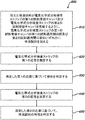
図6は、本発明の実施形態による、体液試料(例えば、全血試料)中の検体(グルコースなど)及び/又はこの体液試料の特性(例えば、ヘマトクリット値)を判定する方法600における段階を描写する、流れ図である。方法600は、加えた体液試料が電気化学式分析検査ストリップの第1の試料受容チャンバ及び第2の試料受容チャンバを充填するように、電気化学式分析検査ストリップの第1の試料受容チャンバの第1の試料適用開口部及び第2の試料適用開口部のいずれかに体液試料を加えることを含む(図6の工程610を参照)。
FIG. 6 depicts steps in a
方法600は、電気化学式分析検査ストリップの第1の応答(例えば、第2の試料受容チャンバの電極からの電気化学応答)を測定し、測定した第1の応答に基づいて体液試料中の検体を判定することも含む(図6の工程620及び630を参照)。
The
工程640及び650において、方法600は、電気化学式分析検査ストリップの第2の応答(例えば、第1の試料受容チャンバの電極からの電気応答)を測定し、第2の測定した応答に基づいて体液試料の特性(ヘマトクリット値又は試薬を含まない方法で判定可能な他の体液試料特性など)を判定することも含む。あるいは、第1の試料受容チャンバは試薬を含まないため、工程640及び650を用いて、試薬を含まない方法で体液試料の第2の検体(例えば、尿酸、アセトアミノフェン、又はドーパミンなど)を測定できる。上記の測定工程及び判定工程は、必要に応じて、好適な付随する測定計を使用して実行することができ、測定工程620及び630は、任意の好適な順序で、又は重複する方法で実行することができる。
In
本開示を知れば、本明細書に説明する本発明の実施形態による電気化学式分析検査ストリップの任意の技術、利益、及び特徴を組み込むように方法600を容易に改変できることは、当業者であれば認識されるであろう。
Those skilled in the art will know that the
本明細書に、好ましい本発明の実施形態が示され、記載されてきたが、このような実施形態は、単なる例として提供されていることが、当業者に明らかであろう。当業者は、目下、本発明から逸脱することなく多数の変更、変化、及び置換を思いつくであろう。本明細書に記載した本発明の実施形態の様々な代替物は、本発明の実施にて使用できることを理解するべきである。以下の特許請求の範囲は、本発明の範囲を定義するとともに、特許請求の範囲に含まれる装置及び方法、並びにそれらの均等物をこれによって網羅することを目的としたものである。 While preferred embodiments of the invention have been shown and described herein, it will be apparent to those skilled in the art that such embodiments are provided by way of example only. Those skilled in the art will now be able to conceive numerous modifications, changes and substitutions without departing from the invention. It should be understood that various alternatives to the embodiments of the invention described herein can be used in the practice of the invention. The following claims are intended to define the scope of the invention and thereby cover the apparatus and methods contained within the claims, and equivalents thereof.
Claims (23)
第1の試料適用開口部と、
第2の試料適用開口部と、
を備える第1の試料受容チャンバと、
前記第1の試料適用開口部と前記第2の試料適用開口部との間の前記第1の試料受容チャンバに配置される第1の電極と、
前記第1の試料適用開口部と前記第2の試料適用開口部との間の前記第1の試料受容チャンバに配置される第2の電極と、
前記第1の電極と前記第2の電極との間で前記第1の試料受容チャンバと交差し、それにより、チャンバ交差部を画定する第2の試料受容チャンバと、
前記第2の試料受容チャンバに配置される、少なくとも1つの第3の電極と、
を含む、電気化学式分析検査ストリップ。 An electrochemical analytical test strip for determining an analyte in a body fluid sample,
A first sample application opening;
A second sample application opening;
A first sample receiving chamber comprising:
A first electrode disposed in the first sample receiving chamber between the first sample application opening and the second sample application opening;
A second electrode disposed in the first sample receiving chamber between the first sample application opening and the second sample application opening;
A second sample receiving chamber that intersects the first sample receiving chamber between the first electrode and the second electrode, thereby defining a chamber intersection;
At least one third electrode disposed in the second sample receiving chamber;
Including, electrochemical formula analysis test strip.
前記チャンバ交差部が、前記第2の試料受容チャンバの試料投入口として構成される、請求項1に記載の電気化学式分析検査ストリップ。 The second sample receiving chamber has a sample inlet;
The electrochemical analytical test strip of claim 1, wherein the chamber intersection is configured as a sample inlet of the second sample receiving chamber.
前記電気絶縁基材層上に配置されたパターン化導体層であって、前記第1の電極、第2の電極、及び少なくとも1つの第3の電極を含むパターン化導体層と、
前記パターン化導体層上に配置された酵素試薬層と、
パターン化スペーサ層と、
親水性層と、
最上層と、を更に含み、
前記電気絶縁基材層、前記パターン化スペーサ層、前記親水性層、及び前記最上層が、前記第1の試料受容チャンバ、前記第2の試料受容チャンバ、前記第1の試料適用開口部、及び前記第2の試料適用開口部を本質的に画定する、請求項1に記載の電気化学式分析検査ストリップ。 An electrically insulating substrate layer;
A patterned conductor layer disposed on the electrically insulating substrate layer, the patterned conductor layer including the first electrode, the second electrode, and at least one third electrode;
An enzyme reagent layer disposed on the patterned conductor layer;
A patterned spacer layer;
A hydrophilic layer;
And further including a top layer,
The electrically insulating substrate layer, the patterned spacer layer, the hydrophilic layer, and the top layer are the first sample receiving chamber, the second sample receiving chamber, the first sample application opening, and The electrochemical analytical test strip of claim 1, essentially defining the second sample application opening.
前記第2の試料受容チャンバ内の体液試料の検体を判定するように構成される、請求項10に記載の電気化学式分析検査ストリップ。 The first working electrode, the second working electrode, and the counter / reference electrode;
The electrochemical analytical test strip of claim 10, configured to determine an analyte of a body fluid sample in the second sample receiving chamber.
加えた体液試料が電気化学式分析検査ストリップの第1の試料受容チャンバ及び第2の試料受容チャンバを充填するように、前記電気化学式分析検査ストリップの前記第1の試料受容チャンバの第1の試料適用開口部及び第2の試料適用開口部のいずれかに前記体液試料を加えることと、
前記第2の試料受容チャンバ内の体液試料によって決まる前記電気化学式分析検査ストリップの第1の応答を測定することと、
前記測定された電気化学的応答に基づいて前記検体を判定することと、を含む、方法。 A method for determining a specimen in a body fluid sample,
First sample application of the first sample receiving chamber of the electrochemical analytical test strip such that the added body fluid sample fills the first sample receiving chamber and the second sample receiving chamber of the electrochemical analytical test strip Adding the body fluid sample to either the opening or the second sample application opening;
Measuring a first response of the electrochemical analytical test strip determined by a body fluid sample in the second sample receiving chamber;
Determining the analyte based on the measured electrochemical response.
前記第2の測定した応答に基づいて、前記体液試料の特性を判定することと、を更に含む、請求項13に記載の方法。 Measuring a second response of the electrochemical analytical test strip determined by a body fluid sample in a first capillary sample receiving chamber;
14. The method of claim 13, further comprising determining a characteristic of the bodily fluid sample based on the second measured response.
第2の電極が、前記第1の試料適用開口部と前記第2の試料適用開口部との間の前記第1の試料受容チャンバに配置され、
前記第2の試料受容チャンバが、前記第1の電極と前記第2の電極との間で前記第1の試料受容チャンバと交差し、それにより、チャンバ交差部を画定し、
少なくとも1つの第3の電極が前記第2の試料受容チャンバに配置される、請求項13に記載の方法。 A first electrode is disposed in the first sample receiving chamber between the first sample application opening and the second sample application opening;
A second electrode is disposed in the first sample receiving chamber between the first sample application opening and the second sample application opening;
The second sample receiving chamber intersects the first sample receiving chamber between the first electrode and the second electrode, thereby defining a chamber intersection;
14. The method of claim 13, wherein at least one third electrode is disposed in the second sample receiving chamber.
前記チャンバ交差部が、前記第2の試料受容チャンバの試料投入口として構成される、請求項18に記載の方法。 The second sample receiving chamber has a sample inlet;
The method of claim 18, wherein the chamber intersection is configured as a sample inlet of the second sample receiving chamber.
Applications Claiming Priority (3)
| Application Number | Priority Date | Filing Date | Title |
|---|---|---|---|
| US13/529,890 US8877023B2 (en) | 2012-06-21 | 2012-06-21 | Electrochemical-based analytical test strip with intersecting sample-receiving chambers |
| US13/529,890 | 2012-06-21 | ||
| PCT/EP2013/062950 WO2013190072A1 (en) | 2012-06-21 | 2013-06-20 | Electrochemical-based analytical test strip with intersecting sample-receiving chambers |
Publications (1)
| Publication Number | Publication Date |
|---|---|
| JP2015520392A true JP2015520392A (en) | 2015-07-16 |
Family
ID=48745905
Family Applications (1)
| Application Number | Title | Priority Date | Filing Date |
|---|---|---|---|
| JP2015517779A Pending JP2015520392A (en) | 2012-06-21 | 2013-06-20 | Electrochemical analytical test strip with crossed sample receiving chambers |
Country Status (13)
| Country | Link |
|---|---|
| US (1) | US8877023B2 (en) |
| EP (1) | EP2864494B1 (en) |
| JP (1) | JP2015520392A (en) |
| KR (1) | KR20150048702A (en) |
| CN (1) | CN104379759B (en) |
| AU (1) | AU2013279297B2 (en) |
| BR (1) | BR112014031835A2 (en) |
| CA (1) | CA2876927C (en) |
| ES (1) | ES2672729T3 (en) |
| HK (1) | HK1209796A1 (en) |
| IN (1) | IN2014DN10436A (en) |
| RU (1) | RU2646493C2 (en) |
| WO (1) | WO2013190072A1 (en) |
Families Citing this family (7)
| Publication number | Priority date | Publication date | Assignee | Title |
|---|---|---|---|---|
| US9523653B2 (en) | 2013-05-09 | 2016-12-20 | Changsha Sinocare Inc. | Disposable test sensor with improved sampling entrance |
| US20150068893A1 (en) * | 2013-09-12 | 2015-03-12 | Joinsoon Medical Technology Co., Ltd. | Biosensor test strip for biosensor test device |
| US9518951B2 (en) | 2013-12-06 | 2016-12-13 | Changsha Sinocare Inc. | Disposable test sensor with improved sampling entrance |
| US9897566B2 (en) | 2014-01-13 | 2018-02-20 | Changsha Sinocare Inc. | Disposable test sensor |
| US9939401B2 (en) | 2014-02-20 | 2018-04-10 | Changsha Sinocare Inc. | Test sensor with multiple sampling routes |
| US9453812B2 (en) * | 2014-06-24 | 2016-09-27 | Lifescan Scotland Limited | End-fill electrochemical-based analytical test strip with perpendicular intersecting sample-receiving chambers |
| US20150369813A1 (en) * | 2014-06-24 | 2015-12-24 | Lifescan Scotland Limited | Analytical test strip with tiered capillary chamber |
Citations (9)
| Publication number | Priority date | Publication date | Assignee | Title |
|---|---|---|---|---|
| JP2003262604A (en) * | 2001-12-10 | 2003-09-19 | Lifescan Inc | Passive sample detection to initiate timing of assay |
| JP2003302403A (en) * | 2002-03-21 | 2003-10-24 | Lifescan Inc | Assay |
| JP2005524842A (en) * | 2002-05-07 | 2005-08-18 | エフ.ホフマン−ラ ロシュ アーゲー | Sampling device for liquid samples |
| JP2006029841A (en) * | 2004-07-13 | 2006-02-02 | Sumitomo Electric Ind Ltd | Sensor chip, measuring instrument using it, and measuring method of very small amount of sample |
| WO2006137549A1 (en) * | 2005-06-24 | 2006-12-28 | Matsushita Electric Industrial Co., Ltd. | Biosensor |
| JP2007524821A (en) * | 2003-06-20 | 2007-08-30 | エフ ホフマン−ラ ロッシュ アクチェン ゲゼルシャフト | Test strip with overhanging sample receiving chamber |
| WO2008047843A1 (en) * | 2006-10-19 | 2008-04-24 | Panasonic Corporation | Method for measuring hematocrit value of blood sample, method for measuring concentration of analyte in blood sample, sensor chip and sensor unit |
| JP2011145291A (en) * | 2009-12-30 | 2011-07-28 | Lifescan Inc | System, device, and method for improving accuracy of biosensor using fill time |
| WO2011156325A2 (en) * | 2010-06-07 | 2011-12-15 | Bayer Healthcare Llc | Underfill management system for a biosensor |
Family Cites Families (37)
| Publication number | Priority date | Publication date | Assignee | Title |
|---|---|---|---|---|
| DE58909505D1 (en) | 1988-06-08 | 1996-01-04 | Philips Patentverwaltung | Synchronous demodulator. |
| AUPN363995A0 (en) | 1995-06-19 | 1995-07-13 | Memtec Limited | Electrochemical cell |
| US5708247A (en) | 1996-02-14 | 1998-01-13 | Selfcare, Inc. | Disposable glucose test strips, and methods and compositions for making same |
| US6241862B1 (en) | 1996-02-14 | 2001-06-05 | Inverness Medical Technology, Inc. | Disposable test strips with integrated reagent/blood separation layer |
| US7494816B2 (en) | 1997-12-22 | 2009-02-24 | Roche Diagnostic Operations, Inc. | System and method for determining a temperature during analyte measurement |
| US6521182B1 (en) | 1998-07-20 | 2003-02-18 | Lifescan, Inc. | Fluidic device for medical diagnostics |
| US6656697B1 (en) * | 1998-09-28 | 2003-12-02 | Lifescan, Inc. | Diagnostics based on tetrazolium compounds |
| US6377894B1 (en) | 1998-11-30 | 2002-04-23 | Abbott Laboratories | Analyte test instrument having improved calibration and communication processes |
| US6676815B1 (en) | 1999-12-30 | 2004-01-13 | Roche Diagnostics Corporation | Cell for electrochemical analysis of a sample |
| US6733655B1 (en) | 2000-03-08 | 2004-05-11 | Oliver W. H. Davies | Measurement of substances in liquids |
| US6488827B1 (en) | 2000-03-31 | 2002-12-03 | Lifescan, Inc. | Capillary flow control in a medical diagnostic device |
| EP1304570A1 (en) | 2001-10-22 | 2003-04-23 | Bioptik Technology, Inc. | Electrochemical electrode test strip and process for preparation thereof |
| US6856125B2 (en) | 2001-12-12 | 2005-02-15 | Lifescan, Inc. | Biosensor apparatus and method with sample type and volume detection |
| EP1396717A1 (en) | 2002-09-03 | 2004-03-10 | Matsushita Electric Industrial Co., Ltd. | Biosensor and measuring method using the same |
| US7144485B2 (en) * | 2003-01-13 | 2006-12-05 | Hmd Biomedical Inc. | Strips for analyzing samples |
| US7462265B2 (en) | 2003-06-06 | 2008-12-09 | Lifescan, Inc. | Reduced volume electrochemical sensor |
| US7488601B2 (en) | 2003-06-20 | 2009-02-10 | Roche Diagnostic Operations, Inc. | System and method for determining an abused sensor during analyte measurement |
| WO2004113910A1 (en) | 2003-06-20 | 2004-12-29 | Roche Diagnostics Gmbh | Devices and methods relating to electrochemical biosensors |
| US7718439B2 (en) | 2003-06-20 | 2010-05-18 | Roche Diagnostics Operations, Inc. | System and method for coding information on a biosensor test strip |
| EP1685393B1 (en) * | 2003-10-31 | 2007-02-21 | Lifescan Scotland Ltd | Electrochemical test strip for reducing the effect of direct interference current |
| US8535497B2 (en) * | 2003-12-04 | 2013-09-17 | Panasonic Corporation | Method of measuring blood component, sensor used in the method, and measuring device |
| DE602004011688D1 (en) * | 2004-03-05 | 2008-03-20 | Egomedical Swiss Ag | ANALYSIS TEST SYSTEM FOR DETERMINING THE CONCENTRATION OF AN ANALYTE IN A PHYSIOLOGICAL LIQUID |
| US7468125B2 (en) | 2005-10-17 | 2008-12-23 | Lifescan, Inc. | System and method of processing a current sample for calculating a glucose concentration |
| US8066866B2 (en) | 2005-10-17 | 2011-11-29 | Lifescan, Inc. | Methods for measuring physiological fluids |
| US20070123801A1 (en) | 2005-11-28 | 2007-05-31 | Daniel Goldberger | Wearable, programmable automated blood testing system |
| US7955484B2 (en) | 2005-12-14 | 2011-06-07 | Nova Biomedical Corporation | Glucose biosensor and method |
| JP2009524046A (en) | 2006-01-20 | 2009-06-25 | エージェンシー フォー サイエンス,テクノロジー アンド リサーチ | Biosensor cell and biosensor array |
| US7811430B2 (en) * | 2006-02-28 | 2010-10-12 | Abbott Diabetes Care Inc. | Biosensors and methods of making |
| US20080083618A1 (en) * | 2006-09-05 | 2008-04-10 | Neel Gary T | System and Methods for Determining an Analyte Concentration Incorporating a Hematocrit Correction |
| KR100915383B1 (en) | 2007-09-04 | 2009-09-03 | 주식회사 휴빛 | Biosensor and readout meter |
| EP2201355B1 (en) | 2007-10-10 | 2017-12-06 | Agamatrix, Inc. | Identification method for electrochemical test strips |
| JP5421382B2 (en) | 2008-10-27 | 2014-02-19 | ライフスキャン・スコットランド・リミテッド | Method and inspection instrument for reducing ESD events |
| US8012428B2 (en) | 2008-10-30 | 2011-09-06 | Lifescan Scotland, Ltd. | Analytical test strip with minimal fill-error sample viewing window |
| US8173008B2 (en) | 2009-06-24 | 2012-05-08 | Lifescan, Inc. | Method for determining an analyte in a bodily fluid sample using an analyte test strip with combination electrode contact and meter identification feature |
| US8632664B2 (en) * | 2009-10-27 | 2014-01-21 | Lifescan Scotland Limited | Test meter for use with a dual chamber, multi-analyte test strip with opposing electrodes |
| US8323467B2 (en) | 2009-10-27 | 2012-12-04 | Lifescan Scotland Limited | Dual chamber, multi-analyte test strip with opposing electrodes |
| US20120048746A1 (en) * | 2010-08-30 | 2012-03-01 | Cilag Gmbh International | Analyte test strip with electrically distinguishable divided electrode |
-
2012
- 2012-06-21 US US13/529,890 patent/US8877023B2/en active Active
-
2013
- 2013-06-20 JP JP2015517779A patent/JP2015520392A/en active Pending
- 2013-06-20 CA CA2876927A patent/CA2876927C/en active Active
- 2013-06-20 RU RU2015101705A patent/RU2646493C2/en not_active IP Right Cessation
- 2013-06-20 KR KR1020157001262A patent/KR20150048702A/en not_active Application Discontinuation
- 2013-06-20 ES ES13733247.4T patent/ES2672729T3/en active Active
- 2013-06-20 CN CN201380032511.5A patent/CN104379759B/en not_active Expired - Fee Related
- 2013-06-20 EP EP13733247.4A patent/EP2864494B1/en active Active
- 2013-06-20 IN IN10436DEN2014 patent/IN2014DN10436A/en unknown
- 2013-06-20 WO PCT/EP2013/062950 patent/WO2013190072A1/en unknown
- 2013-06-20 BR BR112014031835A patent/BR112014031835A2/en not_active Application Discontinuation
- 2013-06-20 AU AU2013279297A patent/AU2013279297B2/en not_active Ceased
-
2015
- 2015-10-27 HK HK15110533.6A patent/HK1209796A1/en unknown
Patent Citations (10)
| Publication number | Priority date | Publication date | Assignee | Title |
|---|---|---|---|---|
| JP2003262604A (en) * | 2001-12-10 | 2003-09-19 | Lifescan Inc | Passive sample detection to initiate timing of assay |
| JP2003302403A (en) * | 2002-03-21 | 2003-10-24 | Lifescan Inc | Assay |
| JP2005524842A (en) * | 2002-05-07 | 2005-08-18 | エフ.ホフマン−ラ ロシュ アーゲー | Sampling device for liquid samples |
| JP2007524821A (en) * | 2003-06-20 | 2007-08-30 | エフ ホフマン−ラ ロッシュ アクチェン ゲゼルシャフト | Test strip with overhanging sample receiving chamber |
| JP2006029841A (en) * | 2004-07-13 | 2006-02-02 | Sumitomo Electric Ind Ltd | Sensor chip, measuring instrument using it, and measuring method of very small amount of sample |
| WO2006137549A1 (en) * | 2005-06-24 | 2006-12-28 | Matsushita Electric Industrial Co., Ltd. | Biosensor |
| WO2008047843A1 (en) * | 2006-10-19 | 2008-04-24 | Panasonic Corporation | Method for measuring hematocrit value of blood sample, method for measuring concentration of analyte in blood sample, sensor chip and sensor unit |
| JP2011145291A (en) * | 2009-12-30 | 2011-07-28 | Lifescan Inc | System, device, and method for improving accuracy of biosensor using fill time |
| WO2011156325A2 (en) * | 2010-06-07 | 2011-12-15 | Bayer Healthcare Llc | Underfill management system for a biosensor |
| JP2013531792A (en) * | 2010-06-07 | 2013-08-08 | バイエル・ヘルスケア・エルエルシー | Underfill management system for biosensors |
Also Published As
| Publication number | Publication date |
|---|---|
| RU2015101705A (en) | 2016-08-10 |
| AU2013279297B2 (en) | 2018-12-06 |
| US8877023B2 (en) | 2014-11-04 |
| US20130341208A1 (en) | 2013-12-26 |
| BR112014031835A2 (en) | 2017-06-27 |
| CN104379759B (en) | 2016-11-16 |
| AU2013279297A1 (en) | 2015-02-05 |
| IN2014DN10436A (en) | 2015-08-21 |
| RU2646493C2 (en) | 2018-03-05 |
| WO2013190072A1 (en) | 2013-12-27 |
| ES2672729T3 (en) | 2018-06-15 |
| KR20150048702A (en) | 2015-05-07 |
| HK1209796A1 (en) | 2016-04-08 |
| EP2864494B1 (en) | 2018-05-30 |
| CA2876927C (en) | 2020-09-08 |
| CN104379759A (en) | 2015-02-25 |
| CA2876927A1 (en) | 2013-12-27 |
| EP2864494A1 (en) | 2015-04-29 |
Similar Documents
| Publication | Publication Date | Title |
|---|---|---|
| JP2015520392A (en) | Electrochemical analytical test strip with crossed sample receiving chambers | |
| US9528958B2 (en) | Analytical test strip with capillary sample-receiving chambers separated by a physical barrier island | |
| JP2015505618A (en) | Electrochemical analytical test strip with filling rate setting reagent layer | |
| KR20130047694A (en) | Analytical test strip with an electrode having electrochemically active and inert areas of a predetermined size and distribution | |
| JP6585636B2 (en) | End-filled electrochemical analytical test strip with vertically intersecting sample receiving chambers | |
| JP2015520393A (en) | Analytical test strip with capillary sample receiving chamber separated by partition junction | |
| US20150369813A1 (en) | Analytical test strip with tiered capillary chamber | |
| US20160202204A1 (en) | Electrochemical-based analytical test strip with ultra-thin discontinuous metal layer | |
| TWI610077B (en) | Electrochemical-based analytical test strip and method for determining an analyte in a bodily fluid sample | |
| TW201501694A (en) | Analytical test strip with capillary sample-receiving chambers separated by a physical barrier island |
Legal Events
| Date | Code | Title | Description |
|---|---|---|---|
| A621 | Written request for application examination |
Free format text: JAPANESE INTERMEDIATE CODE: A621 Effective date: 20160510 |
|
| A977 | Report on retrieval |
Free format text: JAPANESE INTERMEDIATE CODE: A971007 Effective date: 20170220 |
|
| A131 | Notification of reasons for refusal |
Free format text: JAPANESE INTERMEDIATE CODE: A131 Effective date: 20170321 |
|
| A02 | Decision of refusal |
Free format text: JAPANESE INTERMEDIATE CODE: A02 Effective date: 20171017 |