JP2015519806A - Data transmission method and apparatus - Google Patents

Data transmission method and apparatus Download PDF

Info

Publication number
JP2015519806A
JP2015519806A JP2015507588A JP2015507588A JP2015519806A JP 2015519806 A JP2015519806 A JP 2015519806A JP 2015507588 A JP2015507588 A JP 2015507588A JP 2015507588 A JP2015507588 A JP 2015507588A JP 2015519806 A JP2015519806 A JP 2015519806A
Authority
JP
Japan
Prior art keywords
signature
sequence
signature sequences
system value
sequences
Prior art date
Legal status (The legal status is an assumption and is not a legal conclusion. Google has not performed a legal analysis and makes no representation as to the accuracy of the status listed.)
Pending
Application number
JP2015507588A
Other languages
Japanese (ja)
Inventor
ガーカン、ムスタファ
Original Assignee
インペリアル イノベ−ションズ リミテッド
Priority date (The priority date is an assumption and is not a legal conclusion. Google has not performed a legal analysis and makes no representation as to the accuracy of the date listed.)
Filing date
Publication date
Application filed by インペリアル イノベ−ションズ リミテッド, インペリアル イノベ−ションズ リミテッド filed Critical インペリアル イノベ−ションズ リミテッド
Publication of JP2015519806A publication Critical patent/JP2015519806A/en
Pending legal-status Critical Current

Links

Images

Classifications

    • HELECTRICITY
    • H04ELECTRIC COMMUNICATION TECHNIQUE
    • H04BTRANSMISSION
    • H04B7/00Radio transmission systems, i.e. using radiation field
    • H04B7/02Diversity systems; Multi-antenna system, i.e. transmission or reception using multiple antennas
    • H04B7/04Diversity systems; Multi-antenna system, i.e. transmission or reception using multiple antennas using two or more spaced independent antennas
    • H04B7/06Diversity systems; Multi-antenna system, i.e. transmission or reception using multiple antennas using two or more spaced independent antennas at the transmitting station
    • H04B7/0613Diversity systems; Multi-antenna system, i.e. transmission or reception using multiple antennas using two or more spaced independent antennas at the transmitting station using simultaneous transmission
    • H04B7/0678Diversity systems; Multi-antenna system, i.e. transmission or reception using multiple antennas using two or more spaced independent antennas at the transmitting station using simultaneous transmission using different spreading codes between antennas
    • HELECTRICITY
    • H04ELECTRIC COMMUNICATION TECHNIQUE
    • H04BTRANSMISSION
    • H04B1/00Details of transmission systems, not covered by a single one of groups H04B3/00 - H04B13/00; Details of transmission systems not characterised by the medium used for transmission
    • H04B1/69Spread spectrum techniques
    • H04B1/707Spread spectrum techniques using direct sequence modulation
    • H04B1/709Correlator structure
    • H04B1/7093Matched filter type
    • HELECTRICITY
    • H04ELECTRIC COMMUNICATION TECHNIQUE
    • H04JMULTIPLEX COMMUNICATION
    • H04J13/00Code division multiplex systems
    • H04J13/0077Multicode, e.g. multiple codes assigned to one user
    • HELECTRICITY
    • H04ELECTRIC COMMUNICATION TECHNIQUE
    • H04BTRANSMISSION
    • H04B1/00Details of transmission systems, not covered by a single one of groups H04B3/00 - H04B13/00; Details of transmission systems not characterised by the medium used for transmission
    • H04B1/69Spread spectrum techniques
    • H04B1/707Spread spectrum techniques using direct sequence modulation
    • H04B1/7097Interference-related aspects
    • HELECTRICITY
    • H04ELECTRIC COMMUNICATION TECHNIQUE
    • H04BTRANSMISSION
    • H04B7/00Radio transmission systems, i.e. using radiation field
    • H04B7/02Diversity systems; Multi-antenna system, i.e. transmission or reception using multiple antennas
    • H04B7/04Diversity systems; Multi-antenna system, i.e. transmission or reception using multiple antennas using two or more spaced independent antennas
    • H04B7/0413MIMO systems
    • HELECTRICITY
    • H04ELECTRIC COMMUNICATION TECHNIQUE
    • H04JMULTIPLEX COMMUNICATION
    • H04J13/00Code division multiplex systems
    • H04J13/16Code allocation

Abstract

データが送信される複数の並列単入力単出力チャネルあるいは複数の並列マルチ入力マルチ出力チャネルを有する無線データ送信システムにおけるデータ送信方法は、複数のシグネチャシーケンスKの各シグネチャシーケンスkに対して、関連するシグネチャシーケンスkの信号対雑音比を示すシステム値λkを決定するステップと、複数のシグネチャシーケンスKに関連するシステム値λkに従ってデータシンボルの拡散に使用される多くのシグネチャシーケンスK*を決定するステップと、複数のシグネチャシーケンスKに関連するシステム値λkに従って複数のシグネチャシーケンスKからデータシンボルの拡散に使用されるシグネチャシーケンスSを選択する(ここで、選択されたシグネチャシーケンスの数はシグネチャシーケンスK*の決定された数に対応する)ステップと、選択されたシグネチャシーケンスSを用いてデータシンボルを拡散するステップと、を備える。【選択図】図1A data transmission method in a wireless data transmission system having a plurality of parallel single-input single-output channels or a plurality of parallel multi-input multi-output channels through which data is transmitted is associated with each signature sequence k of the plurality of signature sequences K. Determining a system value λk indicative of a signal-to-noise ratio of the signature sequence k; determining a number of signature sequences K * used for spreading data symbols according to a system value λk associated with the plurality of signature sequences K; Selecting a signature sequence S to be used for spreading data symbols from the plurality of signature sequences K according to a system value λk associated with the plurality of signature sequences K (where the number of signature sequences selected is the signature sequence K Comprising a corresponding) step to the determined number of the steps of: spreading the data symbols by using a signature sequence S selected. [Selection] Figure 1

Description

本発明は移動無線システムにおけるデータ送信の分野に関する。より具体的には、しかしこれに限定されずに、本発明の実施形態は、移動無線システムにおける送信用データシンボルの拡散に用いられる拡散シーケンスの決定方法に関する。   The present invention relates to the field of data transmission in mobile radio systems. More specifically, but not limited thereto, the embodiment of the present invention relates to a method for determining a spreading sequence used for spreading data symbols for transmission in a mobile radio system.

移動無線システム技術は、データレートの増大という全般的な目標によって絶え間なく進歩している。第三世代移動無線システムは、符号分割多元接続送信方式を使用しており、世界的に広く採用されてきた。第三世代パートナーシッププロジェクト(3GPP)は、マルチコード広帯域符号分割多元接続(CDMA)システムとして、ユニバーサルモバイルテレコミュニケーションシステム(UMTS)のリリース5仕様における高速ダウンリンクパケットアクセス(HSDPA)システムを開発した。第3世代無線セルラーシステムの成功の大部分は、ダウンリンクスループットを向上するためにHSDPAシステムによって使用された効率的な資源割り当てスキームによるものである。   Mobile radio system technology is constantly evolving with the general goal of increasing data rates. Third generation mobile radio systems use a code division multiple access transmission scheme and have been widely adopted worldwide. The Third Generation Partnership Project (3GPP) has developed a High Speed Downlink Packet Access (HSDPA) system in the Release 5 specification of the Universal Mobile Telecommunications System (UMTS) as a multicode wideband code division multiple access (CDMA) system. Much of the success of third generation wireless cellular systems is due to the efficient resource allocation scheme used by the HSDPA system to improve downlink throughput.

適応変調符号化やハイブリッド自動再送要求などの実現技術が最近利用できるようになったことに伴い、インターネット中心のアプリケーション用のインターネット対応スマートフォンの導入が可能となった。HSDPAシステムに対する傾向は、高データレートアプリケーションを有するスマートフォンのダウンリンクスループットを向上させることである。HSDPAダウンリンクのスループットは広範囲に評価されてきた。マルチ入力マルチ出力(MIMO)HSPDAシステムを使用している場合、実際に達成可能なデータスループットは、理論上界よりはるかに低いことが最近わかってきた。   With the recent realization of implementation technologies such as adaptive modulation coding and hybrid automatic repeat request, it has become possible to introduce Internet-enabled smartphones for Internet-centric applications. The trend towards HSDPA systems is to improve the downlink throughput of smartphones with high data rate applications. The throughput of HSDPA downlink has been extensively evaluated. It has recently been found that the data throughput that can actually be achieved when using a multi-input multi-output (MIMO) HSPDA system is much lower than theoretically.

HSDPAマルチコードCDMAシステムに対するダウンリンクスループット最適化は、二部問題であると考えられてきた。第1の問題は、ダウンリンクユーザに対するシグネチャシーケンスとおよび電力割り当ての問題である。第2の問題は、所与の資源割り当てに対するリンクスループット最適化である。   Downlink throughput optimization for HSDPA multicode CDMA systems has been considered a two-part problem. The first problem is the signature sequence and power allocation problem for downlink users. The second problem is link throughput optimization for a given resource allocation.

第1の問題は、送信のためのユーザのスケジューリングを含む。これは、ダウンリンク送信のために広範囲に試験されてきた。さらに、シグネチャシーケンスの設計と割り当ては、ダウンリンク周波数選択性チャネルに対する総レート最大化の文脈における電力割り当てと共に研究されてきた。送信器シグネチャシーケンスとさらに平均二乗誤差(MSE)最小化受信逆拡散フィルタ係数の反復計算に対する設計法の利用性についても考慮されてきた。さらに、MIMOシステムにおける送受信アンテナ間の所与のチャネルインパルス応答セットに対する総リンクスループットを最大化するシグネチャシーケンスの最適セットが存在することが示されている。さらに、チャネルインパルス応答の所与のセットに対して直交シグネチャシーケンスの最適セットが特定されるシステムも考慮されてきた。   The first problem involves scheduling users for transmission. This has been extensively tested for downlink transmission. Furthermore, signature sequence design and allocation has been studied along with power allocation in the context of total rate maximization for downlink frequency selective channels. The availability of design methods for iterative computation of transmitter signature sequences and further mean square error (MSE) minimized receive despread filter coefficients has also been considered. Furthermore, it has been shown that there exists an optimal set of signature sequences that maximizes the total link throughput for a given set of channel impulse responses between transmit and receive antennas in a MIMO system. In addition, systems have been considered where an optimal set of orthogonal signature sequences is identified for a given set of channel impulse responses.

最適な拡散シーケンスを用いるためには、チャネル状態情報(CSI)が送信器と受信器の両方で利用可能でなければならない。送信器におけるCSIは、ダウンリンクおよびアップリンクチャネルの両方上に多くの信号オーバーヘッドを必要とする。従って、各MIMOダウンリンク送信器アンテナで直交拡散シーケンスの同じセットが使用できるようにすることによって、信号オーバーヘッドを最小化する種々の方法が考慮されてきた。あるアプローチは3GPPで考慮され、ある方法は、直交可変拡散率(OVSF)拡散シーケンスの所与の固定セットサイズを使用するように標準化された。MIMOシステムでは、各アンテナで利用可能なOVSFシグネチャシーケンスの所与の単一セットより大きなシグネチャシーケンスセットサイズが必要である。3GPPでは、拡散シーケンスの所与のセットにプリコーディングウェイトを乗じ、得られた重み付きセットを連結してOVSFセットサイズを増加させる方法が標準化された。各送信シンボルはその後、送信前にそれぞれのMIMOアンテナにおいて、異なる拡散シーケンスで拡散される。従って、各送信シンボルに対して、各アンテナで使用される拡散シーケンスを連結することによって、固有なプリコーディッド拡散シーケンスが作成される。連結された拡散シーケンスは、他の送信シンボル用の送信器で利用可能な拡散シーケンスの残余セットに直交する。しかしながら、周波数選択性マルチパスチャネル上で送信後、拡散シーケンスの直交性は受信端で失われる。リニアMMSEイコライザの後に逆拡散部を用いることによって、各受信器における拡散シーケンスの直交性の復元と、マルチパスチャネル上で送信後の送信シンボルの再生と、ができ得ることが提案された。   In order to use an optimal spreading sequence, channel state information (CSI) must be available at both the transmitter and the receiver. CSI at the transmitter requires a lot of signal overhead on both downlink and uplink channels. Accordingly, various methods for minimizing signal overhead have been considered by allowing each MIMO downlink transmitter antenna to use the same set of orthogonal spreading sequences. One approach was considered in 3GPP, and one method was standardized to use a given fixed set size of orthogonal variable spreading factor (OVSF) spreading sequences. A MIMO system requires a signature sequence set size that is larger than a given single set of OVSF signature sequences available at each antenna. 3GPP has standardized a method for multiplying a given set of spreading sequences by a precoding weight and concatenating the resulting weighted sets to increase the OVSF set size. Each transmit symbol is then spread with a different spreading sequence at each MIMO antenna before transmission. Therefore, a unique precoded spreading sequence is created for each transmission symbol by concatenating the spreading sequence used by each antenna. The concatenated spreading sequence is orthogonal to the remaining set of spreading sequences available at the transmitter for other transmission symbols. However, after transmission over a frequency selective multipath channel, the orthogonality of the spreading sequence is lost at the receiving end. It has been proposed that by using a despreading unit after the linear MMSE equalizer, it is possible to restore the orthogonality of the spreading sequence at each receiver and to regenerate the transmitted symbols after transmission on the multipath channel.

最近の開発では、リニアMMSEイコライザをマルチパスチャネル上で操作時に存在する自己干渉(SI)問題が考慮されている。こうした問題では、HSDPAスループットに対して、現時点で実際上達成可能なレートと理論上界との間のギャップを低減することが目標となる。独立のシンボルレベルMMSEイコライザの後にシンボルレベル連続干渉キャンセル(SIC)スキームを有する受信器は、セル間自己干渉に対応している。HSDPA規格に適合したハイブリッドリニアイコライザ/干渉キャンセル受信器が利用され得ることが提案されている。さらに、HSDPAダウンリンクスループット最適化のためのチップまたはシンボルレベルMMSEイコライザと連携させたSIC受信器が使用でき得ることも提案されている。   Recent developments take into account the self-interference (SI) problem that exists when operating linear MMSE equalizers on multipath channels. In these problems, the goal is to reduce the gap between the currently achievable rate and the theoretical bound for HSDPA throughput. A receiver with a symbol level continuous interference cancellation (SIC) scheme after an independent symbol level MMSE equalizer supports inter-cell self-interference. It has been proposed that a hybrid linear equalizer / interference cancellation receiver compatible with the HSDPA standard can be utilized. It has further been proposed that SIC receivers can be used in conjunction with a chip or symbol level MMSE equalizer for HSDPA downlink throughput optimization.

チップレベルMMSEリニアイコライザの後に逆拡散部とシンボルレベルSICを用いて、チップ間干渉(ICI)とさらにすべてのストリーム間干渉を抑えることが考慮されている。リニアチップレベルMMSEイコライザとしてのチャネル整合フィルタ(CMF)は、マルチパスチャネル中央タップでエネルギーを収集することによって信号対雑音比を最大化することが示されている。チップレベルイコライザは、送信チップシーケンス(これは、1つの送信シンボルストリームを検出するためにその後1つの送信器拡散シーケンスで拡散される)の推定値の作成に用いられる。その後、再生されたシンボルを用いてチップレベルにおける干渉を反復的に除去する。各反復には、チップレベル線形イコライザ係数の計算が必要である。反復の総数は、送信データストリームの数に等しい。   It is considered to suppress inter-chip interference (ICI) and all inter-stream interference by using a despreading unit and a symbol level SIC after the chip level MMSE linear equalizer. A channel matched filter (CMF) as a linear chip level MMSE equalizer has been shown to maximize the signal to noise ratio by collecting energy at the multipath channel center tap. The chip level equalizer is used to create an estimate of the transmit chip sequence (which is then spread with one transmitter spreading sequence to detect one transmit symbol stream). Thereafter, the reproduced symbol is used to repeatedly remove the interference at the chip level. Each iteration requires the calculation of chip level linear equalizer coefficients. The total number of iterations is equal to the number of transmitted data streams.

第2のダウンリンクスループット最大化問題を解決するために、リニアMMSEイコライザを有する受信器と単段SIC検出器とを用いるためには、送信器と受信器との同時最適化が必要である。種々の送信パワー割り当てスキームは、マルチコードMIMOシステムにおける2段階の連続的干渉キャンセルスキームに対する異なるデータストリーム上で引き出せる。送信器パワー最適化を有する2段階のSIC検出スキームによって、マルチコードダウンリンク送信のスループット性能を向上させられる。しかしながら、SIC、イコライザ係数および電力割り当て計算のそれぞれの反復には、受信信号に対する共分散行列の逆行列が必要となる。共分散行列の次元は通常大きく、そのために、受信器における電力割り当て、リニアMMSEイコライザおよびSICの反復実施の計算コストは高くなる。リニアMMSEイコライザとその後のシンボルレベルSICの実施を実際に実現可能とするために、大きな行列の逆行列の簡易化が検討されてきた。   In order to solve the second downlink throughput maximization problem, in order to use a receiver with a linear MMSE equalizer and a single stage SIC detector, simultaneous optimization of the transmitter and the receiver is necessary. Various transmit power allocation schemes can be derived on different data streams for a two-stage continuous interference cancellation scheme in a multi-code MIMO system. A two-stage SIC detection scheme with transmitter power optimization can improve the throughput performance of multi-code downlink transmission. However, each iteration of SIC, equalizer coefficients and power allocation calculations requires an inverse covariance matrix for the received signal. The dimension of the covariance matrix is usually large, which increases the computational cost of power allocation at the receiver, linear MMSE equalizer and SIC iterative implementation. In order to actually realize the implementation of the linear MMSE equalizer and the subsequent symbol level SIC, simplification of the inverse matrix of a large matrix has been studied.

トランシーバ設計を最適化するために種々の試みが行われてきた。マルチコードダウンリンクスループットの最適化のための電力割り当て時には、通常、異なる最適化基準が用いられる。トランシーバ設計の最適化基準に重点的に取り組む技術もあれが、レートと電力の同時割り当てに集中する技術もある。レートと電力の同時割り当て方法に追加するものとして、ゲーム理論のアプローチが最近導入された。上記の割り当て方法は、L.ZhaoとJ.Mark、「Joint rate and power adaptation for radio resource management in uplink wideband code division multiple access systems」、IET Communications、2巻、4号、562〜572ページ(2008年4月)の以下の3表題の下で一般化されている。   Various attempts have been made to optimize transceiver design. When optimizing multi-code downlink throughput, different optimization criteria are usually used. Some technologies focus on optimization criteria for transceiver design, while others focus on simultaneous rate and power allocation. A game theory approach was recently introduced as an addition to the rate and power allocation method. The above allocation method is described in L.L. Zhao and J.H. Mark, “Joint rate and power adaptation for radio resource management in uplink wideband code division multiple access systems,” Volume 2, page 2, 157, IET Communications It has become.

1.第1の基準は、チャネル利得を一定に実現させるレートを最大化する送信パワーを最適化するシステムを含む。代表例は、L.Y.HoonおよびK.S.Wuの「Generalized joint power and rate adaptation in ds−cdma communications over fading channels」、IEEE Transactions on Vehicular Technology、57巻、1号、603〜608ページ(2008年1月)であり、これは、シンボル数と1シンボル当たりのビット数を最適化するものである。この目的は、各受信器における目標の信号対干渉雑音(SINR)比を満たしながら、送信パワーと拡散シーケンスを反復して調節することにより総レートを最大化することである。送信パワーを反復調節して、各受信器における目標の信号対雑音比を満たすことができる。さらに、目標の信号対雑音比(SNR)に対する総送信エネルギーは、各受信器の出力において最小化できる。この種の最適化は、マージン適応ローディング法として既知である。総送信電力を所与の総電力制約未満に維持しながら、送信電力と拡散シーケンスを最適化してマルチコード並列チャネル上の総レートを最大化できる。この種の反復エネルギー割り当ては、レート適応ローディング法として既知である。   1. The first criterion includes a system that optimizes the transmit power that maximizes the rate at which the channel gain is constant. A representative example is L.M. Y. Hoon and K.H. S. Wu's “Generalized joint power and rate adaptation in ds-cdma communicationss over fading channels”, IEEE Transactions on Vehicular Technology, Vol. 3 to 60, 8 This optimizes the number of bits per symbol. The objective is to maximize the total rate by iteratively adjusting the transmit power and spreading sequence while meeting the target signal-to-interference noise (SINR) ratio at each receiver. The transmit power can be iteratively adjusted to meet the target signal-to-noise ratio at each receiver. Furthermore, the total transmit energy for a target signal-to-noise ratio (SNR) can be minimized at the output of each receiver. This type of optimization is known as a margin adaptive loading method. While maintaining the total transmit power below a given total power constraint, the transmit power and spreading sequence can be optimized to maximize the total rate on the multicode parallel channel. This type of iterative energy allocation is known as a rate adaptive loading method.

2.第2の方法は、送信電力、レートおよびシグネチャシーケンス、またさらに受信器のリニアMMSEイコライザを同時に最適化することにより総レートを最大化しながら、受信電力を目標レベルに維持することを目標とする。こうした方法の1例は、S.UlukusおよびA.Yenerの「Iterative transmitter and receiver optimization for cdma networks」、IEEE Transactions on Wireless Communications、3巻、6号、1879〜1884ページ(2004年11月)であり、これは、送信拡散シーケンスとリニアMMSEイコライザを有する受信器とを同時に最適化するものである。この目標は、受信信号電力レベルがそれぞれ送信器に既知の場合、スループットを最大化するか、あるいは各受信器における平均二乗誤差を最小化することである。   2. The second method aims to maintain the received power at the target level while maximizing the total rate by simultaneously optimizing the transmit power, rate and signature sequence, and even the linear MMSE equalizer of the receiver. One example of such a method is S.A. Ulukus and A.M. Yener's “Iterative transmitter and receiver optimization for cdma networks”, IEEE Transactions on Wireless Communications, 3 volumes, 6 issues, 1879-1884 The receiver is optimized at the same time. The goal is to maximize throughput or minimize the mean square error at each receiver when the received signal power level is known to each transmitter.

3.第3の方法の1例は、L.ZhaoおよびJ.Markによる「Joint rate and power adaptation for radio resource management in uplink wideband code division multiple access systems」、IET Communications、2巻、4号、562〜572ページ(2008年4月)に記載されており、ここでは、受信信号電力と干渉信号電力との分配を必要とする評価基準として平均システム性能が用いられている。   3. One example of the third method is L.L. Zhao and J.H. Mark's "Joint rate and power adaptation for radio resource management in uplink wideband code division multiple access systems," vol. 2, vol. 4, vol. 2, fifty-five. Average system performance is used as an evaluation criterion that requires distribution of received signal power and interference signal power.

第1および第2の適応スキームでは、特にマージンおよびレート適応ローディングエリアでは、レートと電力適応は、ユーザの移動によるリンク利得の変化よりはるかに速いと想定される。T.Bogale、L.VandendorpeおよびB.Chaliseの「Robust transceiver optimization for downlink coordinated base station systems:Distributed algorithm、「IEEE Transactions on Signal Processing」、PP巻、99号、1ページ(2011年)には、MIMOダウンリンク送信のための1ユーザ当たり(1ストリーム当たり)のMSE制約に従う総送信電力を最小化するために、ロバストマージン適応ローディングスキームが検討されている。   In the first and second adaptation schemes, particularly in the margin and rate adaptation loading areas, rate and power adaptation is assumed to be much faster than link gain changes due to user movement. T. T. et al. Bogale, L.M. Vandendorpe and B.M. Chalice's “Robust transceiver optimized for downlink coordinated base station systems: 1 for MI, 1 for IE Transactions on Sign, 1” for PP In order to minimize the total transmit power subject to MSE constraints (per stream), a robust margin adaptive loading scheme is being considered.

拡散シーケンスの所与の固定長に対する総レートを最大化するために、レート適応ローディングスキームが与えられている。レート適応最適化法は、N.Vucic、H.BocheおよびS.Shiの「Robust transceiver optimization in downlink multiuser mimo systems」、IEEE Transactions on Signal Processing、57巻、9号、3576〜3587ページ(2009年9月)に提示されており、そこでは、制約つき総送信電力を考慮時に、ダウンリンクMIMOシステムの重み付きMSEが最小化されている。T.Bogale、B.ChaliseおよびL.Vandendorpeの「Robust transceiver optimization for downlink multiuser mimo systems」、IEEE Transactions on Signal Processing、59巻、1号、446〜453ページ(2011年1月)では、基地局アンテナ電力制約を有する重み付きMSEを最小化するために、レート適応ローディングスキームが提供されている。   In order to maximize the total rate for a given fixed length of the spreading sequence, a rate adaptive loading scheme is provided. Rate adaptive optimization methods are described in N.W. Vucic, H.C. Boche and S.M. Shi's “Robust Transceiver Optimization in Downlink Multiuser Mim Systems”, IEEE Transactions on Signal Processing, Vol. 57, No. 9, 3576-3857 (2009) When considered, the weighted MSE of the downlink MIMO system is minimized. T. T. et al. Bogale, B.M. Chalice and L.M. Vendorpe's “Robust transceiver optimization for downlink multisystem mimos systems”, IEEE Transactions on Signal Processing, Volume 59, No. 1, 446-453 To do this, a rate adaptive loading scheme is provided.

現在のHSDPAシステム仕様では、エネルギー均等割り当てスキームを用いて、各チャネルに単一レートあるいは2つの別個のレートをロードしている。MMSE受信器のパラメータは通常、最大〜最小重み付きのSINR基準あるいは総MSE最小化基準のいずれかを用いて最適化される。最近、Z.He、M.GurcanおよびH.Ghaniの「Time−efficient resource allocation algorithm over hsdpa in femtocell networks」、Personal, Indoor and Mobile Radio Communications workshops (PIMRC Workshops)、2010 IEEE 21st International Symposium(2010年9月)、197〜202ページ;およびZ.HeおよびM.Gurcanの「Optimized resource allocation of hsdpa using two group allocation in frequency selective channel」、IEEE International Conference on Wireless Communications Signal Processing、2009 WCSP 2009(2009年11月)、1〜5ページに記載されているように、二群資源割り当てスキームとして既知の反復電力適応法が開発された。この方法では、2つの別個の離散ビットレートが、制約付き総送信電力に従うマルチコードダウンリンクチャネル上にロードされる。   Current HSDPA system specifications load each channel with a single rate or two separate rates using an equal energy allocation scheme. MMSE receiver parameters are typically optimized using either maximum to minimum weighted SINR criteria or total MSE minimization criteria. Recently, Z. He, M.M. Gurcan and H.C. "Time-efficient resource allocation algorithm over hsdpa in femtocell networks" of Ghani, Personal, Indoor and Mobile Radio Communications workshops (PIMRC Workshops), (9 May 2010) 2010 IEEE 21st International Symposium, 197~202 page; and Z. He and M.M. Gurcan's “Optimized resource allocation of hsdpa using two group allocations in W9. An iterative power adaptation method known as a group resource allocation scheme was developed. In this method, two separate discrete bit rates are loaded on the multicode downlink channel according to the constrained total transmit power.

マルチ入力マルチ出力(MIMO)HSPDAシステムを使用する場合、この分野での種々の開発にも拘わらず、実際に達成可能なデータスループットは、理論上界より依然としてはるかに低い。   When using a multi-input multi-output (MIMO) HSPDA system, despite the various developments in the field, the data throughput that can actually be achieved is still much lower than theoretical.

本発明の実施形態では、前述の問題の少なくとも一部の軽減が試みられる。   Embodiments of the present invention attempt to alleviate at least some of the aforementioned problems.

本発明の態様に従って、データが送信される複数の並列単入力単出力チャネルあるいは複数の並列マルチ入力マルチ出力チャネルを有する無線データ送信システムにおけるデータ送信方法が提供される。該データは、送信前に複数の拡散シーケンスによって拡散された複数のデータシンボルで表わされる。該方法は、複数のシグネチャシーケンスKの各シグネチャシーケンスkに対して、関連する前記シグネチャシーケンスkの信号対雑音比を示すシステム値λκを決定するステップと、前記複数のシグネチャシーケンスKに関連する前記システム値λκに従って、データシンボルの拡散に使用される多くのシグネチャシーケンスKを決定するステップと、前記複数のシグネチャシーケンスKに関連する前記システム値λκに従って、前記複数のシグネチャシーケンスKから、前記データシンボルの拡散に使用されるシグネチャシーケンスSを選択するステップであって、選択されたシグネチャシーケンスの数がシグネチャシーケンスKの決定された数に対応するステップと、前記選択されたシグネチャシーケンスSを用いて前記データシンボルを拡散するステップと、を備える。 According to an aspect of the present invention, there is provided a data transmission method in a wireless data transmission system having a plurality of parallel single-input single-output channels or a plurality of parallel multi-input multi-output channels through which data is transmitted. The data is represented by a plurality of data symbols spread by a plurality of spreading sequences before transmission. The method involves, for each signature sequence k of a plurality of signature sequences K, determining a system value λ κ indicative of a signal-to-noise ratio of the associated signature sequence k, and associated with the plurality of signature sequences K Determining a number of signature sequences K * to be used for spreading data symbols according to the system value λ κ , and from the plurality of signature sequences K according to the system value λ κ associated with the plurality of signature sequences K Selecting a signature sequence S to be used for spreading the data symbols, wherein the number of selected signature sequences corresponds to a determined number of signature sequences K * , and the selected signature sequence S Comprising the steps of diffusing the Le, the.

bestが平均システム値

Figure 2015519806
の計算に利用されるシグネチャシーケンスの初期数であり、各シグネチャシーケンスが前記平均システム値
Figure 2015519806
の計算のために等送信エネルギーEを割り当てられるように、Kbest=K〜Kbest=1に対して前記平均システム値
Figure 2015519806
を計算し、前記データシンボルの拡散に使用されるシグネチャシーケンスKの数を決定し、前記平均システム値ベクトル
Figure 2015519806
に従って、前記シンボルの拡散に使用されるシグネチャシーケンスSを選択することによって、シーケンスKの数が決定されてもよく、また、前記シンボルの拡散に使用される前記シグネチャシーケンスSが選択されてもよい。前記平均システム値ベクトル
Figure 2015519806
は、Kbest=1〜Kbest=Kに対して複数の平均システム値
Figure 2015519806
を含む。 K best is the average system value
Figure 2015519806
Is the initial number of signature sequences used to calculate the average system value for each signature sequence
Figure 2015519806
The average system value for K best = K to K best = 1 so that the equal transmission energy E k is assigned for the calculation of
Figure 2015519806
Determine the number of signature sequences K * used to spread the data symbols, and the average system value vector
Figure 2015519806
The number of sequences K * may be determined by selecting the signature sequence S used for spreading of the symbols and the signature sequence S used for spreading of the symbols may be selected Good. Said mean system value vector
Figure 2015519806
A plurality of the average system value for K best = 1~K best = K
Figure 2015519806
including.

best=1〜Kbest=Kに対して以下の式

Figure 2015519806
(ここで、
Figure 2015519806
は前記平均システム値であり、
Figure 2015519806
は、各データシンボルに割り当てできる離散的データレートであって、目標のシステム値
Figure 2015519806
用の複数のP離散的レートに対するp=1〜p=Pの整数値pに対してb〜bの複数のデータレートから選択される。ここで、前記目標のシステム値
Figure 2015519806
は、以下の式
Figure 2015519806
を用いることによって前記データレートbに関して決定される。ここで、
Figure 2015519806
は変調スキームのギャップ値である)が満たされる場合、前記データシンボルの拡散に使用されるシグネチャシーケンスKの数は、シグネチャシーケンスKbestの初期数に等しくなるように決定されてもよく、前記選択されたシグネチャシーケンスSは、最大のシステム値λを有する複数のシグネチャシーケンスKのKシグネチャシーケンスである。 For K best = 1 to K best = K
Figure 2015519806
(here,
Figure 2015519806
Is the average system value,
Figure 2015519806
Is the discrete data rate that can be assigned to each data symbol and is the target system value
Figure 2015519806
For a plurality of P discrete rates for p = 1 to p = P, an integer value p is selected from a plurality of data rates b 1 to b P. Where the target system value
Figure 2015519806
Is the following formula
Figure 2015519806
Is used to determine the data rate b P. here,
Figure 2015519806
Is the gap value of the modulation scheme), the number of signature sequences K * used for spreading the data symbols may be determined to be equal to the initial number of signature sequences K best , The selected signature sequence S is a K * signature sequence of a plurality of signature sequences K having the largest system value λ k .

さらに、Koptが最小システム値

Figure 2015519806
の計算に利用されるシグネチャシーケンスの初期数であり、各シグネチャシーケンスが等送信エネルギーEを割り当てられるように、Kopt=K〜Kopt=1に対して平均システム値
Figure 2015519806
を計算し、シグネチャシーケンスKの数を決定し、Kopt=K〜Kopt=1に対して、複数の最小システム値
Figure 2015519806
を含む最小システム値ベクトル
Figure 2015519806
に従って、前記データシンボルの拡散に使用されるシグネチャシーケンスSを選択することによって、シーケンスKの数がさらに決定されてもよく、また、前記シンボルの拡散に使用される前記シグネチャシーケンスSが選択されてもよい。 Furthermore, K opt is the minimum system value
Figure 2015519806
Is the initial number of signature sequences used in the calculation of the average system value for K opt = K to K opt = 1 so that each signature sequence is assigned an equal transmission energy E k
Figure 2015519806
, Determine the number of signature sequences K * , and for K opt = K to K opt = 1, multiple minimum system values
Figure 2015519806
Minimum system value vector containing
Figure 2015519806
The number of sequences K * may be further determined by selecting the signature sequence S used for spreading the data symbols, and the signature sequence S used for spreading the symbols is selected. May be.

opt=1〜Kopt=Kに対して以下の式

Figure 2015519806
(ここで、
Figure 2015519806
は、前記最小システム値であり、
Figure 2015519806
は、各シンボルに割り当てできる離散的データレートであって、目標のシステム値
Figure 2015519806
用の複数のP離散的レートに対するp=1〜p=Pの整数値pに対してb〜bの複数のデータレートから選択される)が満たされる場合、前記データシンボルの拡散に使用されるシグネチャシーケンスKの数も、シグネチャシーケンスKoptの初期数に等しくなるように決定され、前記選択されたシグネチャシーケンスSは、最大のシステム値λを有する複数のシグネチャシーケンスKのKシグネチャシーケンスである。 For K opt = 1 to K opt = K, the following equation
Figure 2015519806
(here,
Figure 2015519806
Is the minimum system value;
Figure 2015519806
Is the discrete data rate that can be assigned to each symbol, which is the target system value
Figure 2015519806
When selected from a plurality of data rates b 1 ~b P for integer values p of p = 1 to p = P for a plurality of P discrete rate use) is met, use the spread of the data symbols The number of signature sequences K * to be performed is also determined to be equal to the initial number of signature sequences K opt , and the selected signature sequence S is the K * of the plurality of signature sequences K having the largest system value λ k . It is a signature sequence.

該方法は、前記シグネチャシーケンスSの選択前に、最大のシステム値λを有する複数のシグネチャシーケンスKのシグネチャシーケンスkから最小のシステム値λを有する複数のシグネチャシーケンスKのシグネチャシーケンスkまでの複数のシグネチャシーケンスKを順序付けるステップをさらに備えていてもよく、大きなシステム値λは高い信号対雑音比を示し、前記選択されたシグネチャシーケンスSは、前記順序付けられたシグネチャシーケンスの第1のKシグネチャシーケンスである。 Before the selection of the signature sequence S, the method proceeds from a signature sequence k of a plurality of signature sequences K having a maximum system value λ k to a signature sequence k of a plurality of signature sequences K having a minimum system value λ k . The method may further comprise ordering a plurality of signature sequences K, wherein a large system value λ k indicates a high signal-to-noise ratio, and the selected signature sequence S is a first of the ordered signature sequences. K * Signature sequence.

また、該方法は、前記システム値λに従って、データレート

Figure 2015519806
を前記複数の選択されたシグネチャシーケンスSに割り当てるステップをさらに備えていてもよく、前記割り当てられたデータレートbpkの合計は、1シンボル周期当たりの総データレートに対応する。シグネチャシーケンスKの数決定時に、前記データレート
Figure 2015519806
が割り当てられてもよい。 The method also includes a data rate according to the system value λ k.
Figure 2015519806
May be further assigned to the plurality of selected signature sequences S, wherein the sum of the assigned data rates b pk corresponds to the total data rate per symbol period. When determining the number of signature sequences K * , the data rate
Figure 2015519806
May be assigned.

総データレートは、以下の式を満たす最大の整数mEEを見出すことによって決定されてもよく、

Figure 2015519806
等エネルギー割り当てに対応する場合では、シグネチャシーケンス(k−mES)の第1の群は、離散的データレート
Figure 2015519806
でのデータ送信に用いられ、残余mESのシグネチャシーケンスを含むシグネチャシーケンスの第2の群は、離散的データレート
Figure 2015519806
でのデータ送信に用いられる。 The total data rate may be determined by finding the largest integer m EE that satisfies the following equation:
Figure 2015519806
In the case corresponding to equal energy allocation, the first group of signature sequences (k * −m ES ) is the discrete data rate
Figure 2015519806
A second group of signature sequences used for data transmission over the network including the signature sequence of the remaining m ES is a discrete data rate
Figure 2015519806
Used for data transmission in

さらに、総データレートは、以下の式を満たす最大の整数mESを見出すことによって決定されてもよく、

Figure 2015519806
シグネチャシーケンス(k−mES)の第1の群は、離散的データレート
Figure 2015519806
でのデータ送信に用いられ、残余mESのシグネチャシーケンスを含むシグネチャシーケンスの第2の群は、離散的データレート
Figure 2015519806
でのデータ送信に用いられる。 Further, the total data rate may be determined by finding the largest integer m ES that satisfies the following equation:
Figure 2015519806
The first group of signature sequences (k * −m ES ) is a discrete data rate
Figure 2015519806
A second group of signature sequences used for data transmission over the network including the signature sequence of the remaining m ES is a discrete data rate
Figure 2015519806
Used for data transmission in

該方法は、総送信エネルギーに対する1シンボル周期当たりの総データレートを最大化するために、前記割り当てられた送信データレート

Figure 2015519806
と対応するシステム値λに従って、送信エネルギーを前記選択された複数のシグネチャシーケンスKに割り当てるステップをさらに備えていてもよく、前記割り当てられた送信エネルギーの合計は総送信エネルギーEに対応する。 The method uses the allocated transmission data rate to maximize the total data rate per symbol period relative to the total transmission energy.
Figure 2015519806
And assigning transmission energy to the selected plurality of signature sequences K according to the corresponding system value λ k , the sum of the assigned transmission energy corresponding to the total transmission energy E T.

前記送信エネルギーEk,iは、連続的干渉キャンセル(SIC)スキームのない受信器に基づいて以下の式を用いて反復的に決定されてもよい。

Figure 2015519806
ここで、iは、反復数であり、
Figure 2015519806
は、共分散行列Ci−1を反転することにより決定される逆共分散行列である。ここで、共分散行列Ci−1は、拡張整合フィルタシグネチャシーケンス行列Qと拡張振幅行列
Figure 2015519806
に関して、以下の式を用いて表される。
Figure 2015519806
ここで、
Figure 2015519806
はクロネッカー積であり、振幅行列
Figure 2015519806
は送信エネルギーに関して表され、2σは雑音分散であり、Nは受信器アンテナ数であり、Nは処理利得であり、Lはマルチパス遅延拡散長であり、拡張整合フィルタ受信器シーケンス行列Qは、以下の式
Figure 2015519806
に従って表される。ここで、Qは、前のシンボル周期に対する整合フィルタシーケンスを表わし、Qは、次のシンボル周期に対する整合フィルタシーケンスを表し、QとQは、
Figure 2015519806

Figure 2015519806
に従って表される。ここで、
Figure 2015519806

Figure 2015519806
は、シグネチャシーケンスKの数の前と次のシンボル周期に対するISI整合フィルタシーケンスであり、
Figure 2015519806
はシフト行列であり、整合フィルタ逆拡散シグネチャシーケンス行列
Figure 2015519806
は、以下の式Q=HSで決定される。ここで、
Figure 2015519806
は、長さNの複数の送信シグネチャシーケンス
Figure 2015519806
に対する整合フィルタ受信器逆拡散シグネチャシーケンスであり、Hは、周波数選択性マルチパスチャネルに対するMIMOシステムコンボリューション行列であり、コンボリューション行列Hは、以下の式
Figure 2015519806
に従って表され、Nは送信器アンテナの総数であり、受信器アンテナnと送信器アンテナnの各対間にあって、チャネルインパルス応答ベクトル
Figure 2015519806
を有するチャネルコンボリューション行列H(nr,nt)は、以下の式
Figure 2015519806
に関して表される。 The transmit energy E k, i may be iteratively determined using the following equation based on a receiver without a continuous interference cancellation (SIC) scheme.
Figure 2015519806
Where i is the number of iterations,
Figure 2015519806
Is an inverse covariance matrix determined by inverting the covariance matrix C i−1 . Here, the covariance matrix C i−1 is an extended matched filter signature sequence matrix Q e and an extended amplitude matrix.
Figure 2015519806
Is expressed using the following equation:
Figure 2015519806
here,
Figure 2015519806
Is the Kronecker product and the amplitude matrix
Figure 2015519806
Is expressed in terms of transmit energy, 2σ 2 is the noise variance, N R is the number of receiver antennas, N is the processing gain, L is the multipath delay spread length, and the extended matched filter receiver sequence matrix Q e is the following formula
Figure 2015519806
Represented in accordance with Where Q 1 represents the matched filter sequence for the previous symbol period, Q 2 represents the matched filter sequence for the next symbol period, and Q 1 and Q 2 are
Figure 2015519806
,
Figure 2015519806
Represented in accordance with here,
Figure 2015519806
When
Figure 2015519806
Is the ISI matched filter sequence for the number of signature sequences K * and for the next symbol period,
Figure 2015519806
Is a shift matrix and matched filter despread signature sequence matrix
Figure 2015519806
Is determined by the following equation Q = HS. here,
Figure 2015519806
Is a plurality of transmission signature sequences of length N
Figure 2015519806
Is the matched filter receiver despread signature sequence for H, where H is the MIMO system convolution matrix for the frequency selective multipath channel, and the convolution matrix H is
Figure 2015519806
N T is the total number of transmitter antennas, between each pair of receiver antenna n r and transmitter antenna n t , and the channel impulse response vector
Figure 2015519806
A channel convolution matrix H (nr, nt) with
Figure 2015519806
Expressed in terms of

送信エネルギーEk,iも連続的干渉キャンセル(SIC)スキームを有する受信器に基づいて、以下の式

Figure 2015519806
を解くことによって反復的に決定されてもよく、平均システム値は、所与の逆共分散行列
Figure 2015519806
に対して、シグネチャシーケンスKの数決定に用いられ、前記逆共分散行列
Figure 2015519806
は、共分散行列
Figure 2015519806
の逆行列であり、前記共分散行列Ck−1は、
Figure 2015519806
が用いられる場合、k=1、…、Kに対して、以下の式
Figure 2015519806
を解くことによって反復的に決定され、目標のSNR
Figure 2015519806
は、以下の式
Figure 2015519806
を用いて決定され、重み付け係数ζ、ζ、ζ、ζ、ζ、ζおよびζは、以下の式
Figure 2015519806
を用いて、SIC受信器共分散行列
Figure 2015519806

Figure 2015519806
および
Figure 2015519806
から構築され、距離ベクトル
Figure 2015519806
は、以下の式
Figure 2015519806
を用いて決定される。 The transmission energy E k, i is also based on a receiver with a continuous interference cancellation (SIC) scheme,
Figure 2015519806
And the mean system value is given by the given inverse covariance matrix
Figure 2015519806
For the number of signature sequences K * , the inverse covariance matrix
Figure 2015519806
Is the covariance matrix
Figure 2015519806
And the covariance matrix C k−1 is
Figure 2015519806
Is used, for k = 1,..., K * ,
Figure 2015519806
And iteratively determined by solving for the target SNR
Figure 2015519806
Is the following formula
Figure 2015519806
The weighting coefficients ζ, ζ 1 , ζ 2 , ζ 3 , ζ 4 , ζ 5 and ζ 6 are
Figure 2015519806
SIC receiver covariance matrix using
Figure 2015519806
,
Figure 2015519806
and
Figure 2015519806
Constructed from the distance vector
Figure 2015519806
Is the following formula
Figure 2015519806
Is determined.

Figure 2015519806
を有する逆共分散行列
Figure 2015519806
、さらにエネルギー割り当てEおよび
Figure 2015519806

Figure 2015519806

Figure 2015519806
、Eとσを有するMIMOシステムパラメータのセットに対して、前記逆共分散行列
Figure 2015519806
を、逆共分散行列
Figure 2015519806
とエネルギーEとを用い、距離ベクトル
Figure 2015519806

Figure 2015519806
および
Figure 2015519806
を決定し、重み付け係数ζ、ζ、ζ、ζ、ζ、ζおよびζを決定し、以下の式
Figure 2015519806
において、k=1、…、Kに対して割り当てられたエネルギーEを用いて重み付きエネルギー項ζとζを決定し、以下の式
Figure 2015519806
を解くことによって暫定行列Z、Z、Zを決定し、以下の式
Figure 2015519806
を解くことによって低減された逆共分散行列
Figure 2015519806
を決定し、以下の式
Figure 2015519806
を用いて前記逆共分散行列
Figure 2015519806
を構築することによって、k=1、…、Kに対して、k=1から始めて構築し、
前記重み付きエネルギー項ζは、以下の式
Figure 2015519806
を解くことによって決定され、
前記暫定行列Zは、以下の式
Figure 2015519806
を用いて決定され、
前記距離ベクトル
Figure 2015519806
は、以下の式
Figure 2015519806
を用いて決定される。
Figure 2015519806
Inverse covariance matrix with
Figure 2015519806
And further the energy allocation E k and
Figure 2015519806
,
Figure 2015519806
,
Figure 2015519806
, E k and σ 2 for a set of MIMO system parameters, the inverse covariance matrix
Figure 2015519806
, The inverse covariance matrix
Figure 2015519806
And energy E k and distance vector
Figure 2015519806
,
Figure 2015519806
and
Figure 2015519806
And determine the weighting coefficients ζ, ζ 1 , ζ 2 , ζ 3 , ζ 4 , ζ 5, and ζ 6 , and
Figure 2015519806
, Determine the weighted energy terms ζ 1 and ζ 2 using the energy E k assigned to k = 1,..., K * .
Figure 2015519806
To determine the provisional matrices Z 1 , Z 2 , Z 3, and
Figure 2015519806
Inverse covariance matrix reduced by solving
Figure 2015519806
Determine the following formula
Figure 2015519806
Using the inverse covariance matrix
Figure 2015519806
For k = 1, ..., K * , starting from k = 1,
The weighted energy term ζ is given by
Figure 2015519806
Is determined by solving
The provisional matrix Z 4 has the following formula:
Figure 2015519806
Is determined using
The distance vector
Figure 2015519806
Is the following formula
Figure 2015519806
Is determined.

総データレートbT,Kを最大化するシグネチャシーケンスの総数を決定することにより、シグネチャシーケンスKの数を決定するステップを備える反復注水系連続ビットローディング法を用いて、シグネチャシーケンスKの数を決定してもよく、また、データの拡散に使用されるシグネチャシーケンスSを選択してもよい。 The total data rate b T, by determining the total number of signature sequences that maximizes the K, using an iterative injection system continuous bit-loading method comprising the step of determining the number of signature sequences K *, the number of signature sequences K * Or a signature sequence S used for data diffusion may be selected.

複数の整合フィルタシグネチャシーケンス

Figure 2015519806
および
Figure 2015519806
に対して、反復注水最適化法は、シグネチャシーケンスKoptの初期数を設定するステップと、シグネチャシーケンスKoptの初期数に関連するシステム値λを決定するステップと、以下の式
Figure 2015519806
を用いて、エネルギー割り当てEに対するチャネルSNRベクトル
Figure 2015519806
を決定するステップと、以下の式
Figure 2015519806
を用いて、注水定数KWFを決定するステップ(ここで、Eは総送信エネルギー)と、以下の式
Figure 2015519806
を用いて、複数のシグネチャシーケンスKの各シグネチャシーケンスkに割り当てるエネルギーEを決定するステップと、
整合フィルタシグネチャシーケンスの順序付けられたリストを提供するために昇順に、シグネチャシーケンスKoptの初期数に関連するシステム値
Figure 2015519806
に従って、整合フィルタシグネチャシーケンス
Figure 2015519806

Figure 2015519806
および
Figure 2015519806
を再順序付けるステップと、整合フィルタシグネチャシーケンスの順序付けられたリストの第1の整合フィルタシーケンス
Figure 2015519806

Figure 2015519806
および
Figure 2015519806
を削除するステップと、割り当てられたエネルギーEが負の場合、Kopt=Kopt−1を設定するステップと、上記のステップを繰り返すステップと、下式
Figure 2015519806
を用いて送信されるビットbT,K総数を決定するステップと、K=Koptを用いて考慮中の複数のシグネチャシーケンスKのシグネチャシーケンスKの数を決定するステップと、さらに備えていてもよい。 Multiple matched filter signature sequences
Figure 2015519806
and
Figure 2015519806
Respect, repeated injection optimization method includes the steps of determining and setting the initial number of signature sequences K opt, the system value lambda k related to the initial number of signature sequences K opt, the following formula
Figure 2015519806
And the channel SNR vector for the energy allocation E k
Figure 2015519806
And the following formula
Figure 2015519806
With, determining the water injection constant K WF (where, E T is the total transmit energy) and the following formula
Figure 2015519806
To determine an energy E k to be assigned to each signature sequence k of the plurality of signature sequences K;
System values related to the initial number of signature sequences K opt in ascending order to provide an ordered list of matched filter signature sequences
Figure 2015519806
According to the matched filter signature sequence
Figure 2015519806
,
Figure 2015519806
and
Figure 2015519806
Reordering and a first matched filter sequence in an ordered list of matched filter signature sequences
Figure 2015519806
,
Figure 2015519806
and
Figure 2015519806
, If the assigned energy E 1 is negative, setting K opt = K opt −1, repeating the above steps, and
Figure 2015519806
Determining the total number of bits b T, K transmitted using , and determining the number of signature sequences K * of the plurality of signature sequences K under consideration using K * = K opt. May be.

反復注水法は、シグネチャシーケンスの総数を最初にK=Kと設定し、送信される総データレートと、シグネチャシーケンスKがK=1になるまでK=K−1の値に対してシグネチャシーケンスKの数と、を決定し、総データレートを最大化する複数のシグネチャシーケンスKに対するシグネチャシーケンスKの数を選択することによって、シグネチャシーケンス(K)の数を決定してもよい。 The iterative irrigation method initially sets the total number of signature sequences as K * = K, and for the total data rate transmitted and the value of K * = K−1 until the signature sequence K * becomes K * = 1. Determining the number of signature sequences K * and determining the number of signature sequences (K * ) by selecting the number of signature sequences K * for a plurality of signature sequences K that maximizes the total data rate Also good.

システム値は以下の式によって決定されてもよく、
λ=γε
ここで、γは、MMSE受信器の逆分散ユニットの出力における信号対雑音比であり、εは、該逆分散ユニットの出力における平均二乗誤差であり、平均二乗誤差は、λ=1−εによるシステム値に関係する。
The system value may be determined by the following formula:
λ k = γ k ε k
Where γ k is the signal to noise ratio at the output of the inverse dispersion unit of the MMSE receiver, ε k is the mean square error at the output of the inverse dispersion unit, and the mean square error is λ k = 1. related to the system value by -ε k.

さらに、システム値λは、連続的干渉キャンセル(SIC)スキームのない受信器に基づく以下の式に従って決定されてもよく、

Figure 2015519806
ここで、Cは、以下の式
Figure 2015519806
を用いて、拡張整合フィルタシグネチャシーケンス行列Qと拡張振幅行列
Figure 2015519806
に関して表され、ここで、
Figure 2015519806
はクロネッカー積であり、振幅行列
Figure 2015519806
であり、ここで、整合フィルタ逆拡散シグネチャシーケンス行列
Figure 2015519806
は、以下の式
Figure 2015519806
を用いて拡張整合フィルタシグネチャシーケンス行列Qを構築するために形成され、ここで、Qは、前のシンボル周期に対する整合フィルタシーケンスを表わし、Qは、次のシンボル周期に対する整合フィルタシーケンスを表し、QとQは、
Figure 2015519806

Figure 2015519806
に従って表され、
Figure 2015519806

Figure 2015519806
は、前と次のシンボル周期に対するISI整合フィルタシーケンスである。 Further, the system value λ k may be determined according to the following equation based on a receiver without a continuous interference cancellation (SIC) scheme:
Figure 2015519806
Where C is the following equation:
Figure 2015519806
And the extended matched filter signature sequence matrix Q e and the extended amplitude matrix
Figure 2015519806
Represented here, where
Figure 2015519806
Is the Kronecker product and the amplitude matrix
Figure 2015519806
Where the matched filter despread signature sequence matrix
Figure 2015519806
Is the following formula
Figure 2015519806
Is used to construct an extended matched filter signature sequence matrix Q e , where Q 1 represents the matched filter sequence for the previous symbol period, and Q 2 represents the matched filter sequence for the next symbol period. And Q 1 and Q 2 are
Figure 2015519806
,
Figure 2015519806
Represented according to
Figure 2015519806
When
Figure 2015519806
Is the ISI matched filter sequence for the previous and next symbol periods.

システム値λも、連続的干渉キャンセル(SIC)スキームを有する受信器に基づく以下の式に従って決定されてもよい。

Figure 2015519806
ここで、Ck−1は、
Figure 2015519806
を使用時に、k=k=1、…、Kに対して以下の式
Figure 2015519806
を解くことにより反復的に決定される共分散行列であり、
Figure 2015519806

Figure 2015519806
は、前と次のシンボル周期に対するISI整合フィルタシーケンスであり、
Figure 2015519806
は、整合フィルタ逆分散シグネチャシーケンスである。 The system value λ k may also be determined according to the following equation based on a receiver having a continuous interference cancellation (SIC) scheme.
Figure 2015519806
Where C k−1 is
Figure 2015519806
At the time of use, k = k = 1, ... , the following equation for the K *
Figure 2015519806
Is a covariance matrix that is iteratively determined by solving
Figure 2015519806
When
Figure 2015519806
Is the ISI matched filter sequence for the previous and next symbol periods;
Figure 2015519806
Is a matched filter inverse variance signature sequence.

本発明の別の態様に従って、上記のいずれかの方法を実行するように配列された装置が提供される。該装置は無線送信基地局であってもよい。   In accordance with another aspect of the present invention, there is provided an apparatus arranged to perform any of the above methods. The apparatus may be a radio transmission base station.

本発明のさらに別の態様に従って、コンピュータで実施可能であり、使用時には、上記のいずれかの方法を実行するように操作可能なコンピュータ可読媒体が提供される。   In accordance with yet another aspect of the invention, a computer-readable medium is provided that is computer-implementable and, in use, operable to perform any of the methods described above.

本発明の実施形態では、連続的干渉キャンセルスキームをモデル化するように拡張されたHSDPA MIMOシステムに対するシステムモデルが提供される。該スキームは、反復共分散行列の逆行列法と統合されてもよい。これによって、分散行列の逆行列が簡素化される。こうした方法は、送信エネルギーの計算と、所与のHSDPA MIMOシステムの各並列チャネルに対する送信データ速度の割り当てと、に反復使用できる。   In an embodiment of the present invention, a system model for an HSDPA MIMO system is provided that is extended to model a continuous interference cancellation scheme. The scheme may be integrated with an iterative covariance matrix inverse matrix method. This simplifies the inverse of the variance matrix. Such a method can be used iteratively to calculate transmit energy and assign a transmit data rate for each parallel channel of a given HSDPA MIMO system.

本発明の実施形態では、送信エネルギー割り当て前に送信ビットレートを得る新規な方法が提供される。割り当てられたレートは、所与の総送信エネルギーに対する総容量を最適化しながら、送信エネルギーを計算するために、反復共分散行列の逆行列と共に使用できる。総容量は、拡散シーケンスの数を動的に変化させることにより向上できる。このスキームでは、MIMO送信器アンテナと受信器アンテナ間の所与の送信チャネルコンボリューション行列に対して用いられる、最適な送信数の特定と拡散シーケンスが必要である。   In an embodiment of the present invention, a novel method for obtaining a transmission bit rate prior to transmission energy allocation is provided. The assigned rate can be used with the inverse of the iterative covariance matrix to calculate the transmit energy while optimizing the total capacity for a given total transmit energy. The total capacity can be improved by dynamically changing the number of spreading sequences. This scheme requires the identification of the optimal number of transmissions and the spreading sequence used for a given transmission channel convolution matrix between the MIMO transmitter antenna and the receiver antenna.

本発明の実施形態では、以前に開発された二群等SNRアルゴリズムと等エネルギー割り当てスキームを用いて、拡散シーケンスの最適数を見出す2つの異なるアルゴリズムが提供される。   In embodiments of the present invention, two different algorithms are provided that find the optimal number of spreading sequences using previously developed two-group equal SNR algorithms and equal energy allocation schemes.

本発明の実施形態では、提案された拡散スキームの最適数と拡散シーケンス選択スキームを使用時に、システム値上界に近い性能が達成される。   In embodiments of the present invention, performance close to the system value upper bound is achieved when using the optimal number of proposed spreading schemes and spreading sequence selection schemes.

本発明の実施形態では、シンボルレベルリニアMMSEイコライザとその後に単一レベルSIC検出器を有する受信器が提供される。本発明の実施形態では、シングルユーザマルチコードダウンリンク送信システムに対して、送信電力と受信器が最適化される。受信器は好都合に、周波数選択性チャネル上でのマルチコードダウンリンク送信の各反復に対する大きな共分散行列を反転する必要なしに、ICIとISI干渉を反復して抑えられる。   In an embodiment of the present invention, a receiver having a symbol level linear MMSE equalizer followed by a single level SIC detector is provided. In embodiments of the present invention, transmit power and receiver are optimized for a single user multicode downlink transmission system. The receiver is advantageously able to iteratively suppress ICI and ISI interference without having to invert the large covariance matrix for each iteration of multicode downlink transmission over a frequency selective channel.

本発明の実施形態ではさらに、離散的送信レートと制約付き総送信電力を使用時に、シングルユーザー用ダウンリンクの総容量を最大化する、反復的送信電力/エネルギー適応スキームが提供される。   Embodiments of the present invention further provide an iterative transmit power / energy adaptation scheme that maximizes the total capacity of a single user downlink when using discrete transmit rates and constrained total transmit power.

本発明の実施形態は、総レートを最大化するシステム値最適化基準として既知のエネルギー適応基準を利用する。該システム値アプローチは、合計平均二乗誤差(MMSE)最小化基準の修正版である。   Embodiments of the present invention utilize a known energy adaptation criterion as a system value optimization criterion that maximizes the total rate. The system value approach is a modified version of the total mean square error (MMSE) minimization criterion.

本発明の実施形態では、受信電力と干渉電力の分配あるいは各目的地の受信信号電力を目標レベルに維持することのいずれにも注目せずに、電力/エネルギー適応方法が反復して実施される。該方法では、リニアMMSEおよびSIC受信器を用いて信号対雑音比を所望の目標レベルに維持するために、各チャネルに割り当てられた電力を最適化することによって総送信レートが最大化できる。   In embodiments of the present invention, the power / energy adaptation method is iteratively implemented without paying attention to either the distribution of received power and interference power or maintaining the received signal power at each destination at a target level. . In the method, the total transmission rate can be maximized by optimizing the power allocated to each channel in order to maintain the signal to noise ratio at a desired target level using linear MMSE and SIC receivers.

本発明の実施形態に従って、MIMO送信器と受信器および多数の拡散シーケンスを利用するシステムが考慮される。周波数選択性マルチパスチャネル上での送信前に、複数の拡散シーケンスを用いてデータシンボルを拡散してもよい。受信器では、各拡散シーケンス

Figure 2015519806
は、受信器の信号対雑音比γを示す関連のシステム値λを有していてもよい。各拡散シーケンスに対するシステム値λは、送信マルチパスチャネルに依存してもよい。そのようなものとして、ここに開示される送信システム最適化は、最大のシステム値を有する拡散シーケンスを保持し、所与の総送信エネルギーEに対応する所与の総受信信号対雑音比に対して用いられる拡散シーケンスの数を特定してもよい。 In accordance with an embodiment of the present invention, a system utilizing a MIMO transmitter and receiver and multiple spreading sequences is considered. Prior to transmission on the frequency selective multipath channel, the data symbols may be spread using multiple spreading sequences. At the receiver, each spreading sequence
Figure 2015519806
May have an associated system value λ k indicative of the signal-to-noise ratio γ k of the receiver. The system value λ k for each spreading sequence may depend on the transmission multipath channel. As such, the transmission system optimization disclosed herein maintains a spreading sequence having the maximum system value, for a given total received signal-to-noise ratio corresponding to the given total transmission energy E T You may specify the number of spreading sequences used for.

添付図を参照して本発明の典型的な実施形態を説明する。
HSDPA MIMO送信器と受信器の配列を示す概略図である。 連続的干渉キャンセル受信器の概略図である。
Exemplary embodiments of the present invention will be described with reference to the accompanying drawings.
It is the schematic which shows the arrangement | sequence of a HSDPA MIMO transmitter and a receiver. FIG. 3 is a schematic diagram of a continuous interference cancellation receiver.

説明と図面の全体に亘って、同じ参照番号は同じ部分を指す。   Like reference numerals refer to like parts throughout the description and drawings.

図1を参照して、本発明の第1の実施形態を説明する。   A first embodiment of the present invention will be described with reference to FIG.
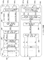
図1において、送信器100は、k=1、…、Kに対する入力ベクトル

Figure 2015519806
を受信し、この入力データは符号化されて符号化ユニット内にマッピングされる。その後、符号化ユニット101によって作成された、k=1、…、Kに対する符号化データ
Figure 2015519806
は、適応変調および符号化ユニット102によって処理されて各チャネルk=1、…、Kに対するシンボルベクトル
Figure 2015519806
に変換される。送信シンボルエネルギーはその後、電力制御ユニット103を用いて調節される。エネルギー重み付きデータシンボルは、ベクトル生成ユニット104を用いて、シンボル周期ρ=1、…、N(x)上に重み付きシンボルを含む送信ベクトル
Figure 2015519806
に変換される。データシンボルはその後、拡散ユニット105の複数の拡散シーケンスによって拡散される。拡散されたシンボルは次に、パルス整形フィルタ106によりフィルタリングされて、MIMO送信器107a、107b、…107Nから送信用送信信号が作成される。 In FIG. 1, the transmitter 100 receives an input vector for k = 1,..., K * .
Figure 2015519806
This input data is encoded and mapped in the encoding unit. Thereafter, encoded data for k = 1,..., K * created by the encoding unit 101
Figure 2015519806
The adaptive modulation and each channel k = 1 is processed by the coding unit 102, ..., symbol vectors for K *
Figure 2015519806
Is converted to The transmitted symbol energy is then adjusted using the power control unit 103. The energy weighted data symbols are transmitted using vector generation unit 104 including weighted symbols on symbol period ρ = 1,..., N (x).
Figure 2015519806
Is converted to The data symbols are then spread by a plurality of spreading sequences of spreading unit 105. Spread symbols is then is filtered by a pulse shaping filter 106, MIMO transmitters 107a, 107 b, the transmit signal for transmission is generated from ... 107N T.

送信信号はその後、受信器200のMIMO受信器201a、201b、…、201Nによって受信される。受信信号はその後、周波数ダウン変換およびフィルタリングされて、チップ整合フィルタユニット202によってチップ周期間隔でサンプリングされる。サンプリングされたデータベクトルはその後、ベクトル連結ユニット203によって連結され、逆分散ユニット204により逆拡散シーケンスを用いて逆分散されて、各シンボル周期に対して送信データシンボルが推定される。その後、推定されたデータシンボルは再整理され、受信器ベクトルマッピングユニット205と判定ユニット206とを用いて各拡散シーケンスに対して推定されたデータが作成される。   The transmission signal is then received by the MIMO receivers 201a, 201b,. The received signal is then frequency down-converted and filtered and sampled by chip matched filter unit 202 at chip period intervals. The sampled data vectors are then concatenated by a vector concatenation unit 203 and despread using a despreading sequence by a despreading unit 204 to estimate transmission data symbols for each symbol period. The estimated data symbols are then rearranged and estimated data for each spreading sequence is created using receiver vector mapping unit 205 and decision unit 206.

上記の送信器と受信器の各ユニットは、実際のMIMO送信器107a、107b、…、107Nおよび受信器、201a、201b、…、201Nは別にして、ソフトウェア内で実施される。   The above transmitter and receiver units are implemented in software apart from the actual MIMO transmitters 107a, 107b,..., 107N and the receivers 201a, 201b,.

本発明のこの実施形態のシステムは、このシステムによって達成される全体のデータレートを向上させるために、上記のデータ送信装置でどの拡散シーケンスが使用できるかを決定するように設計されている。本発明の実施形態は、データレートを上げるために、拡散ユニット105による拡散にどの拡散シーケンスを利用すべきかを決定するためにシステム値を利用するという原則に基づいている。   The system of this embodiment of the present invention is designed to determine which spreading sequences can be used in the above data transmitter to improve the overall data rate achieved by this system. Embodiments of the present invention are based on the principle of using system values to determine which spreading sequence should be used for spreading by spreading unit 105 to increase the data rate.

該システム値は、データが送信されるチャネルの特徴を表す変数である。システム値は、逆拡散ユニットの出力における規格化された使用可能な信号エネルギーである。単一の規格化された総エネルギーとシステム値との差によって、逆拡散ユニットの出力における平均二乗誤差が得られる。規格化されたエネルギー、システム値と平均二乗誤差との比は、逆拡散ユニットの出力における信号対雑音比が得られる。従って、システム値は、チャネル上の信号対雑音比を示す。   The system value is a variable that represents the characteristics of the channel through which data is transmitted. The system value is the normalized usable signal energy at the output of the despreading unit. The difference between the single normalized total energy and the system value gives the mean square error at the output of the despreading unit. The ratio of normalized energy, system value and mean square error gives the signal to noise ratio at the output of the despreading unit. Thus, the system value indicates the signal to noise ratio on the channel.

システム値によって、送信チャネルの特徴を前提として、どの拡散シーケンスがより強いか、また、どれがより弱いかに関しての決定ができる。そのために、より弱い拡散シーケンスを送信処理から除外できる結果、より強い拡散シーケンスだけを用いてデータシンボルを拡散でき、従って、データレートの増加が達成される。   Depending on the system values, it is possible to decide which spreading sequences are stronger and which are weaker given the characteristics of the transmission channel. As a result, the weaker spreading sequence can be excluded from the transmission process, so that only the stronger spreading sequence can be used to spread the data symbols, thus increasing the data rate.

以下、本発明の第1の実施形態によるシステム値の決定について説明する。
本発明のこの実施形態では、NとNの合計の送受信アンテナと、それぞれが、所与の総エネルギーE、p=1,2,…,Pのビットレートセット

Figure 2015519806
からの1シンボル当たりのビットレートがbPkビットを有して実現可能な拡散シーケンスと、を有する図1に示すマルチコードCDMAダウンリンクシステムが考慮される。 Hereinafter, determination of a system value according to the first embodiment of the present invention will be described.
In this embodiment of the present invention, the total transmission-reception antenna of the N T and N R, respectively, given total energy E T, p = 1,2, ... , bit rate set of P
Figure 2015519806
A multi-code CDMA downlink system shown in FIG. 1 is considered having a spreading sequence that can be realized with a bit rate per symbol from b Pk bits.

特定の拡散シーケンスセットに対応した弱いチャネルを除外することによって、並列送信チャネルの数は、1チャネル当たり1シンボルを送信するK拡散シーケンスに低減される。各チャネルの意図したシンボルに対するデータは、k=1、…、Kに対して

Figure 2015519806
次元のベクトル
Figure 2015519806
に置かれる。その後、これらのデータパケットはそれぞれチャネル符号化されて、(B×1)次元のベクトル
Figure 2015519806
を作成し、Mコンスタレーションを有する直交振幅変調スキーム(QAM)を用いてシンボルにマッピングされて、1シンボル当たりb=logMビットレートでデータ送信される。チャネル符号化レートは
Figure 2015519806
であり、実現可能な離散レートは、p=1、…、P(Pは利用可能な離散データレート数)に対して、
Figure 2015519806
で与えられる。 By excluding weak channels corresponding to a specific spreading sequence set, the number of parallel transmission channels is reduced to K * spreading sequences that transmit one symbol per channel. The data for the intended symbol of each channel is for k = 1, ..., K *
Figure 2015519806
Dimensional vector
Figure 2015519806
Placed in. Each of these data packets is then channel coded to a (B × 1) dimensional vector.
Figure 2015519806
And is mapped to symbols using a quadrature amplitude modulation scheme (QAM) with M constellation and transmitted at a rate of b = log 2 M bit rate per symbol. The channel coding rate is
Figure 2015519806
The possible discrete rates are p = 1,..., P (P is the number of available discrete data rates),
Figure 2015519806
Given in.

データは、送信時間間隔(TTI)でパケット内で送信され、1パケット当たりに送信されたシンボルの数はN(x)で表わされる。ここで、N(x)

Figure 2015519806
であり、Nは拡散シーケンス長であり、Tはチップ周期であり、NTはシンボル周期である。周期ρ=1、…、N(x)に亘る各ベクトル
Figure 2015519806
に対応する送信シンボルは、各チャネルk=1、…、Kに対する(N(x)×1)次元のシンボルベクトル
Figure 2015519806
の作成に用いられる。送信の全ブロックは、次のように定義された(N(x)×K)次元の送信シンボル行列として表わせる。
Figure 2015519806
送信ベクトル
Figure 2015519806
は、シンボル周期ρ=1、…、N(x)に亘って、k=1、…、Kに対する単位平均エネルギー
Figure 2015519806
を有するシンボルを含む。電力割り当ては、拡散前のシンボルに対して行なわれる。すべてのKチャネル用のエネルギーは、
Figure 2015519806
であるように総エネルギーEに従う振幅行列
Figure 2015519806
に保存される。 Data is transmitted in packets at a transmission time interval (TTI), and the number of symbols transmitted per packet is represented by N (x) . Where N (x) is
Figure 2015519806
Where N is the spreading sequence length, T c is the chip period, and NT c is the symbol period. Each vector over the period ρ = 1,..., N (x)
Figure 2015519806
The transmission symbol corresponding to is a (N (x) × 1) -dimensional symbol vector for each channel k = 1,..., K * .
Figure 2015519806
Used to create All blocks of transmission can be represented as a (N (x) × K * ) dimensional transmission symbol matrix defined as follows.
Figure 2015519806
Send vector
Figure 2015519806
The symbol period [rho = 1, ..., over the N (x), k = 1 , ..., unit average energy for K *
Figure 2015519806
Including symbols having Power allocation is performed on symbols before spreading. The energy for all K * channels is
Figure 2015519806
Amplitude matrix according to the total energy E T as is
Figure 2015519806
Saved in.

エネルギー割り当て後、振幅重み付きシンボルは、n=1、…、Nに対するN×K次元の拡散シーケンス

Figure 2015519806
で拡散される。合計N送信アンテナとNN×Kのシグネチャシーケンス行列を有するMIMOシステムは、以下の式のように形成される。
Figure 2015519806
ここで、
Figure 2015519806
である。すべてのシンボル周期ρ=1、…、N(x)において、N長送信ベクトル
Figure 2015519806
は、n=1、…、Nに対する
Figure 2015519806
アンテナの入力で生成される。ベクトル
Figure 2015519806
の各要素は、アップコンバータモジュレータを使用して変調される前に、チップ周期Tの整数倍でパルス整形フィルタに供給されて、
Figure 2015519806
送信器アンテナを使用して、所望の送信キャリア周波数で拡散信号を送信する。 After energy allocation, the amplitude weighted symbols are N t = 1,..., N × K * -dimensional spreading sequence for NT
Figure 2015519806
Diffused in. A MIMO system with a total of N T transmit antennas and a N T N × K * signature sequence matrix is formed as:
Figure 2015519806
here,
Figure 2015519806
It is. N length transmission vectors in all symbol periods ρ = 1,..., N (x)
Figure 2015519806
For n t = 1, ..., NT
Figure 2015519806
Generated by antenna input. vector
Figure 2015519806
Are supplied to the pulse shaping filter at an integer multiple of the chip period T c before being modulated using the upconverter modulator,
Figure 2015519806
A transmitter antenna is used to transmit the spread signal at the desired transmission carrier frequency.

各TTIでは、パイロット信号は、各受信器でチャネル状態を推定して送信器に推定値をフィードバックする。チャネル状態は、そのTTIに対しては変化しないと考えられる。

Figure 2015519806
送信器アンテナから
Figure 2015519806
受信器アンテナまでのすべての拡散シーケンスチャネルにおけるブロックN(x)のシンボルはすべて、L分離可能なパスを有するマルチパス環境では同じチャネル状態を経験する。これは、チャネルインパルス応答関数
Figure 2015519806
と、その対応する(N+L−1)×N)次元のチャネルコンボリューション行列
Figure 2015519806
によって以下のように表わせる。
Figure 2015519806
全(N(N+L−1)×NN)次元のMIMOチャネルコンボリューション行列は以下のように形成できる。
Figure 2015519806
In each TTI, the pilot signal estimates the channel condition at each receiver and feeds back the estimated value to the transmitter. The channel state is considered not to change for that TTI.
Figure 2015519806
From transmitter antenna
Figure 2015519806
All symbols of block N (x) in all spreading sequence channels up to the receiver antenna will experience the same channel condition in a multipath environment with L separable paths. This is the channel impulse response function
Figure 2015519806
And its corresponding (N + L−1) × N) dimensional channel convolution matrix
Figure 2015519806
Can be expressed as follows.
Figure 2015519806
A full (N R (N + L−1) × N T N) -dimensional MIMO channel convolution matrix can be formed as follows.
Figure 2015519806

受信器で得られるマルチパスは、チャネルインパルス応答が送信器シグネチャシーケンスSとコンボリューションするので、逆分散シグネチャシーケンスを送信アンテナにおける拡散シグネチャシーケンスより長くなる。N(N+L−1)×K次元の受信器整合フィルタシグネチャシーケンス行列は次のように得られる。

Figure 2015519806
ここで、N(N+L−1)次元のベクトル
Figure 2015519806
は受信器整合フィルタ逆分散シーケンスである。これによって、シンボル間干渉とコード間干渉が生じる。受信器のISIは、N(N+L−1)×3K次元の拡張整合フィルタ行列を形成することによって対応できる。
Figure 2015519806
ここで、シグネチャシーケンス行列
Figure 2015519806

Figure 2015519806
は、以下のように表される。
Figure 2015519806
The multipath obtained at the receiver makes the inverse distributed signature sequence longer than the spreading signature sequence at the transmit antenna because the channel impulse response convolves with the transmitter signature sequence S. An N R (N + L−1) × K * -dimensional receiver matched filter signature sequence matrix is obtained as follows:
Figure 2015519806
Where N R (N + L−1) -dimensional vector
Figure 2015519806
Is the receiver matched filter inverse dispersion sequence. This causes intersymbol interference and intercode interference. The receiver's ISI can be accommodated by forming an extended matched filter matrix of N R (N + L−1) × 3K * dimensions.
Figure 2015519806
Where the signature sequence matrix
Figure 2015519806
When
Figure 2015519806
Is expressed as follows.
Figure 2015519806

Figure 2015519806

Figure 2015519806
は両方とも、前のシンボル周期および次のシンボル周期に対応する受信器シグネチャシーケンスであり、ISIの処理に使用される。(N+L−1)×(N+L−1)次元の行列は、
Figure 2015519806
のように定義される。簡略化のために、添字はJ行列記法から省略されるであろう。行列Jが列ベクトルに作用する場合、N個の0で最上位列を落とすNチップで該列をダウンシフトする。送信器と受信器のクロックが完全に同期していると仮定して、受信信号は、最初にベースバンドに変換される。各受信器チップ整合フィルタの出力における信号は、チップ周期間隔Tでサンプリングされる。
Figure 2015519806
受信器におけるチップ整合フィルタは、シンボル周期ρ間に処理される総(N+L−1)サンプル数
Figure 2015519806
を有する。
Figure 2015519806
受信信号行列は、
Figure 2015519806
として与えられる。シンボル周期においてすべてのアンテナ素子を含む受信整合フィルタは、ρ=1、…、N(x)−1に対して、サイズN(N+L−1)のベクトル
Figure 2015519806
によって与えられる。シンボル周期ρに亘る受信信号ベクトルは、送信ベクトル
Figure 2015519806
に関して次のように与えられる。
Figure 2015519806
ここで、
Figure 2015519806
はクロネッカー積であり、N(N+L−1)次元の雑音ベクトル
Figure 2015519806
は、一次元の雑音分散
Figure 2015519806
を有する雑音共分散行列
Figure 2015519806
を有する。MIMO受信器用のN(N+L−1)×N(x)次元の受信信号行列は、
Figure 2015519806
のように与えられる。
Figure 2015519806
When
Figure 2015519806
Are both receiver signature sequences corresponding to the previous symbol period and the next symbol period, and are used for ISI processing. The (N + L−1) × (N + L−1) dimensional matrix is
Figure 2015519806
Is defined as follows. For simplicity, subscripts will be omitted from the J matrix notation. If the matrix J N is applied to the column vector to downshift the said column with N chips dropping uppermost row of N 0. Assuming that the transmitter and receiver clocks are fully synchronized, the received signal is first converted to baseband. The signal at the output of each receiver chip matched filter is sampled at the chip period interval Tc .
Figure 2015519806
The chip matched filter at the receiver is the total number of (N + L−1) samples processed during the symbol period ρ.
Figure 2015519806
Have
Figure 2015519806
The received signal matrix is
Figure 2015519806
As given. A receive matched filter including all antenna elements in a symbol period is a vector of size N R (N + L−1) for ρ = 1,..., N (x) −1.
Figure 2015519806
Given by. The received signal vector over the symbol period ρ is the transmitted vector
Figure 2015519806
Is given as follows.
Figure 2015519806
here,
Figure 2015519806
Is the Kronecker product and has an N R (N + L−1) -dimensional noise vector
Figure 2015519806
Is one-dimensional noise variance
Figure 2015519806
Noise covariance matrix with
Figure 2015519806
Have An N R (N + L−1) × N (x) dimensional received signal matrix for a MIMO receiver is
Figure 2015519806
Is given as follows.

シンボル周期ρに亘る受信信号ベクトル

Figure 2015519806
は、
Figure 2015519806
を用いた、送信シンボルベクトル
Figure 2015519806
の推定値としてのサイズK列ベクトル
Figure 2015519806
の作成に使用される。 Received signal vector over symbol period ρ
Figure 2015519806
Is
Figure 2015519806
Transmit symbol vector using
Figure 2015519806
Size K * column vector as an estimate of
Figure 2015519806
Used to create

(N+L−1)×K次元の行列

Figure 2015519806
は、k=1、…、Kに対して、MMSEリニアイコライザ逆拡散フィルタ係数
Figure 2015519806
を有する。
Figure 2015519806
および、j≠kに対して相互相関
Figure 2015519806
が最小限にされることを確実にするために、規格化されたMMSE逆拡散フィルタ係数ベクトルが以下の式によって与えられる。
Figure 2015519806
ここで、
Figure 2015519806
は、受信信号ベクトル
Figure 2015519806
のN(N+L−1)×N(N+L−1)次元の共分散行列である。(13)で与えられる共分散行列Cは、
Figure 2015519806

Figure 2015519806
を使用時、k=1、…、Kに対し、次の式を用いて反復的に計算できる。
Figure 2015519806
N R (N + L−1) × K * dimensional matrix
Figure 2015519806
MMSE linear equalizer despread filter coefficients for k = 1,..., K *
Figure 2015519806
Have
Figure 2015519806
And cross-correlation for j ≠ k
Figure 2015519806
In order to ensure that is minimized, the normalized MMSE despread filter coefficient vector is given by:
Figure 2015519806
here,
Figure 2015519806
Is the received signal vector
Figure 2015519806
N R (N + L−1) × N R (N + L−1) -dimensional covariance matrix. The covariance matrix C given by (13) is
Figure 2015519806
When
Figure 2015519806
, K = 1,..., K * can be iteratively calculated using the following formula:
Figure 2015519806

各受信器の出力では、送信信号

Figure 2015519806
と推定された信号
Figure 2015519806
間の平均二乗誤差
Figure 2015519806
は、k=1、…、Kに対して、
Figure 2015519806
のように与えられる。ここで、
Figure 2015519806
は、各受信器の出力における信号対雑音比(SNR)であり、λは、
Figure 2015519806
で与えられるシステム値である。 At the output of each receiver, the transmitted signal
Figure 2015519806
Estimated signal
Figure 2015519806
Mean square error between
Figure 2015519806
For k = 1, ..., K,
Figure 2015519806
Is given as follows. here,
Figure 2015519806
Is the signal-to-noise ratio (SNR) at the output of each receiver, and λ k is
Figure 2015519806
The system value given by.

今やシステム値が定義されたので、全体システム性能を向上させるためのシステム値に従った弱いチャネルの決定方法についてより詳細に議論する。   Now that system values have been defined, we discuss in more detail how weak channels are determined according to system values to improve overall system performance.

MIMOダウンリンク総容量最適化の主な目的は、ラグランジュの乗数λを有するラグランジュの双対目的関数

Figure 2015519806
に基づく総MMSE最小化基準を使用して、総MMSE
Figure 2015519806
を最小化することである。目標関数は、総レート
Figure 2015519806
を最大限にする。ここで、
Figure 2015519806
は、k=1、…、Kに対して、各拡散シーケンスシンボルに割り当てられるビット数である。エネルギーが割り当てられると、対応するレートが決定できる。項εおよびEはレート
Figure 2015519806
の関数として表される場合、(16)で与えられる最適化によって、エネルギー制約
Figure 2015519806
に従うEとλに対する解が提供される。平均二乗誤差エネルギーεは、システム値λに関して、ε=1−λとして与えられる。(16)のエネルギーEは、(15)で特定されたように、
Figure 2015519806
によってシステム値λと関係する。各チャネル上で送信されるビットレート
Figure 2015519806
は、
Figure 2015519806
に関してSNR
Figure 2015519806
と関係する。ここで、
Figure 2015519806
はギャップ値である。目標SNR
Figure 2015519806
は、
Figure 2015519806
で与えられ、また、1シンボル当たり
Figure 2015519806
ビットの送信に必要な目標のシステム値
Figure 2015519806
は、
Figure 2015519806
で与えられる。 The main objective of the MIMO downlink total capacity optimization is Lagrangian dual objective function with Lagrange multiplier λ
Figure 2015519806
Using the total MMSE minimization criterion based on
Figure 2015519806
Is to minimize. The goal function is the total rate
Figure 2015519806
To maximize. here,
Figure 2015519806
Is the number of bits assigned to each spreading sequence symbol for k = 1,..., K * . Once energy is allocated, the corresponding rate can be determined. The terms ε k and E k are rates
Figure 2015519806
Is expressed as a function of the energy constraint by the optimization given in (16)
Figure 2015519806
A solution for E k and λ according to is provided. The mean square error energy ε k is given as ε k = 1−λ k with respect to the system value λ k . The energy E k of (16), as specified in (15),
Figure 2015519806
By the system value λ k . Bit rate transmitted on each channel
Figure 2015519806
Is
Figure 2015519806
With respect to SNR
Figure 2015519806
Related to. here,
Figure 2015519806
Is the gap value. Target SNR
Figure 2015519806
Is
Figure 2015519806
Per symbol
Figure 2015519806
Target system value required to send bits
Figure 2015519806
Is
Figure 2015519806
Given in.

本発明のこの実施形態では、最適化パラメータはすべてシステム値に関して表されるので、システム値は、(15)の与えられる

Figure 2015519806
を用いて計算できる。しかしながら、SICスキームを利用する他の実施形態で認められるように、違ったシステム値決定が使用されるであろう。 In this embodiment of the invention, all optimization parameters are expressed in terms of system values, so the system value is given by (15)
Figure 2015519806
Can be used to calculate. However, different system value determinations may be used, as will be appreciated in other embodiments utilizing SIC schemes.

従って、本発明のこの実施形態では、平均システム値は

Figure 2015519806
となるであろう。ここで、総トータルシステム値λは、k=1、…、Kに対して
Figure 2015519806
の時、最大となる。提案されたSICスキームの有無にかかわらずMMSE受信器にとって、総システム容量は
Figure 2015519806
である。ここで、
Figure 2015519806
はギャップ値である。(20)において、平均システム値λmeanに対応する容量を有する総チャネル数の乗算によって、総容量に非常に近い近似値が得られる。 Thus, in this embodiment of the invention, the average system value is
Figure 2015519806
It will be. Here, the total total system value λ T is, k = 1, ..., with respect to K *
Figure 2015519806
At the maximum. For MMSE receivers with or without the proposed SIC scheme, the total system capacity is
Figure 2015519806
It is. here,
Figure 2015519806
Is the gap value. In (20), an approximation very close to the total capacity is obtained by multiplying the total number of channels having a capacity corresponding to the average system value λ mean .

本発明のこの第1の実施形態では、反復するビットローディング法は、事前のエネルギー割り当ての必要なしに、離散的レートを割り当てるために作成される。所与の総数Imaxの間反復することによって提案されたSICスキームなしにMIMOシステムを使用する場合、この反復的方法は、所与の総エネルギーEで作動する。しかしながら、SICスキームと共に使用される場合、同様なアプローチが適用される。システムパラメータは、N、N、σ、K、L、Hであると考えられる。シグネチャシーケンス

Figure 2015519806
は、行列Q、QおよびQを構築する目的で利用可能になる。開始時には、各反復法は、
Figure 2015519806

Figure 2015519806
および
Figure 2015519806
としたシーケンス
Figure 2015519806

Figure 2015519806
および
Figure 2015519806
を作成して、k=1、…、Kに対して、初期システム値λを作成するであろう。 In this first embodiment of the invention, an iterative bit loading method is created for assigning discrete rates without the need for prior energy assignment. When using a MIMO system without the proposed SIC scheme by iterating for a given total number I max , this iterative method works with a given total energy E T. However, a similar approach applies when used with SIC schemes. The system parameters are considered to be N R , N T , σ 2 , K * , L, H. Signature sequence
Figure 2015519806
Becomes available for the purpose of constructing the matrices Q, Q 1 and Q 2 . At the beginning, each iteration is
Figure 2015519806
,
Figure 2015519806
and
Figure 2015519806
Sequence
Figure 2015519806
,
Figure 2015519806
and
Figure 2015519806
To create an initial system value λ k for k = 1,.

マルチパスチャネルによって、システム値λはランダムに変化する振幅を有する。このことは、除外されなければ、より高いデータレートの送信に使用され得る良好なチャネルを除外することによって、総レートを低下させ得る悪いチャネルとして、一部の拡散シーケンスを含むことに繋がり得る。システム値の使用に基づくシグネチャシーケンス選択スキームは、弱いシグネチャシーケンスを特定して除外するために組み込まれてもよい。 Due to the multipath channel, the system value λ k has a randomly varying amplitude. This can lead to including some spreading sequences as bad channels that can reduce the overall rate by excluding good channels that can be used for higher data rate transmissions if not excluded. A signature sequence selection scheme based on the use of system values may be incorporated to identify and exclude weak signature sequences.

反復法は、シグネチャシーケンスの最適数Kとそれらが現われる順序を特定するために、Sからシーケンスのサブセットを選択する。該方法では、シーケンスの総数はK=KからK=1まで変わる。該方法では、最初に総数K=Kの拡散シーケンスをとり、各拡散シーケンスに等しく利用可能な総エネルギーを割り当てることによって、関連するシステム値をすべて計算する。システム値とおよび対応する拡散シーケンスは、昇順にシステム値を有するように順序付けられる。平均システム値とさらにシグネチャシーケンスセットは、対応する数の拡散シーケンスに対して記録される。最小のシステム値に対応する拡散シーケンスは削除され、拡散シーケンスの数は、K=K−1を用いて低減される。また、拡散シーケンスの数をK=KからK=1まで変えてその数を低減させるために、対応するシステム値と平均システム値の計算、シグネチャシーケンスの順序付けおよび除去処理を反復する。拡散シーケンスの数をK=1からK=Kまで変えるには、すべての拡散シーケンスが同じ送信レートを使用している場合には、平均システム値を用いて各拡散シーケンス上で送信されるデータレートを計算する。データレートbと拡散シーケンスの対応する数との乗算を最大化する拡散シーケンスの数は、拡散シーケンスの最適数Kになるように選択される。シグネチャシーケンスの最適数に対応する記録されたシグネチャシーケンスセットは、シグネチャシーケンスの順序付けられたセットになるように選択される。拡散シーケンスの最適数に対応するデータレートbと、離散的データレートセット

Figure 2015519806
で利用可能な次のデータレートbp+1と、対応する目標のシステム値と、を用いて、1シンボル当たりbビットレートでのデータ送信に使用されるチャネルK−mの数と、シグネチャシーケンスの最適数に対応する平均システム値を考慮することによって、bp+1ビットレートでのデータ送信に使用されるチャネルmの数と、が決定される。データレートbとbp+1および拡散シーケンスK−mおよびmの数を決定後、要求されたレートbおよびbp+1でのデータ送信に必要なエネルギーを、所与の総エネルギー制約
Figure 2015519806
に対して反復計算する。 The iterative method selects a subset of sequences from S to identify the optimal number of signature sequences K * and the order in which they appear. In this method, the total number of sequences varies from K = K to K = 1. The method first calculates all relevant system values by taking a total number K = K of spreading sequences and assigning each spreading sequence an equal total available energy. System values and corresponding spreading sequences are ordered to have system values in ascending order. Average system values and further signature sequence sets are recorded for a corresponding number of spreading sequences. The spreading sequence corresponding to the smallest system value is deleted and the number of spreading sequences is reduced using K = K-1. Further, in order to change the number of spreading sequences from K = K to K = 1 and reduce the number, the calculation of the corresponding system value and average system value, the ordering of signature sequences and the removal process are repeated. To change the number of spreading sequences from K = 1 to K = K, if all spreading sequences use the same transmission rate, the data rate transmitted on each spreading sequence using the average system value Calculate The number of spreading sequences to maximize multiplication with a corresponding number of data rates b p and the spreading sequence is selected to be the optimum number K * of the spreading sequence. The recorded signature sequence set corresponding to the optimal number of signature sequences is selected to be an ordered set of signature sequences. And data rate b p corresponding to the optimum number of spreading sequence, the discrete data rate set
Figure 2015519806
The number of channels K * −m used for data transmission at the bp bit rate per symbol, using the next data rate bp + 1 available at 1 and the corresponding target system value, and the signature sequence The number of channels m used for data transmission at the b p + 1 bit rate is determined by considering the average system value corresponding to the optimal number of. After determining the number of data rates b p and b p + 1 and the spreading sequence K * -m and m, the energy required to transmit data at the requested rate b p and b p + 1, given total energy constraints
Figure 2015519806
Iteratively calculate for.

次に、シーケンスの最適数、それらが出現する順序、データレートおよびエネルギー割り当ての詳細について説明する。   Next, the details of the optimal number of sequences, the order in which they appear, the data rate and energy allocation are described.

該方法では、割り当てられたエネルギーとサイズKのベクトル

Figure 2015519806
の要素としての順序付けられたシグネチャシーケンスの数とを戻すようにK=Kで開始することにより、k=1、…、Kに対するエネルギーEとさらにKとが動的に調節される。ベクトル
Figure 2015519806
は、k=1に対して
Figure 2015519806
を用いることによって初期化できる。開始時、k=1、…、Kに対して(15)で与えられるシステム値λのセットは、(13)で与えられる
Figure 2015519806

Figure 2015519806
を用いてサイズKベクトル
Figure 2015519806
の要素として作成される。その後、ベクトル
Figure 2015519806
を用いて、
Figure 2015519806

Figure 2015519806
および
Figure 2015519806
を用いた整合フィルタシーケンスと、k=1に対して
Figure 2015519806
を用いたベクトル
Figure 2015519806
と、が再整理される。ここで、aは、
Figure 2015519806
の最小要素kthの指数である。 In the method, a vector of allocated energy and size K *
Figure 2015519806
By starting with the sequence Tagged number and the returning way K * = K signature sequences as an element, k = 1, ..., are adjusted dynamically and energy E k further K * for K * . vector
Figure 2015519806
For k = 1
Figure 2015519806
Can be initialized by using At the start, the set of system values λ k given in (15) for k = 1,..., K * is given in (13)
Figure 2015519806
When
Figure 2015519806
Using size K * vector
Figure 2015519806
Created as an element of Then vector
Figure 2015519806
Using,
Figure 2015519806
,
Figure 2015519806
and
Figure 2015519806
For a matched filter sequence with k = 1
Figure 2015519806
Vector using
Figure 2015519806
And rearranged. Where a k is
Figure 2015519806
Is the index of the minimum element k th of.

各反復開始時、k=1、…、Kに対して(15)で与えられるシステム値λのセットは、変数N、L、N、σ、エネルギーEの更新セット、ベクトル

Figure 2015519806
および
Figure 2015519806
を用い、さらに、(13)で得られるC−1を用いて構築されるであろう。各反復ループ内で、
Figure 2015519806
で与えられるシステム値は昇順で再順序付けられる。必要に応じて、最適数Kと対応するエネルギーは更新される。
Figure 2015519806
の最小要素kthの指数を用いて、シーケンス
Figure 2015519806
および
Figure 2015519806
と、割り当てられたエネルギーEと、ベクトル
Figure 2015519806
の要素と、が再順序付けられる。反復が進行すると必要に応じて、反復アルゴリズムにおけるシーケンス
Figure 2015519806
とエネルギーの数およびベクトル
Figure 2015519806
のサイズは低減するであろう。所与の反復数に到達すると、反復ループは終了するが、そうでなければ、最初から始まる反復が繰り返される。 At the start of each iteration, the set of system values λ k given in (15) for k = 1,..., K * is the updated set of variables N, L, N R , σ 2 , energy E k , vector
Figure 2015519806
and
Figure 2015519806
And will be constructed using C- 1 obtained in (13). Within each iteration loop,
Figure 2015519806
System values given in are reordered in ascending order. As needed, the optimal number K * and the corresponding energy are updated.
Figure 2015519806
Sequence using the index of the minimum element k th of
Figure 2015519806
and
Figure 2015519806
And the allocated energy E k and the vector
Figure 2015519806
Are reordered. A sequence in the iterative algorithm as needed as the iteration proceeds
Figure 2015519806
And energy numbers and vectors
Figure 2015519806
Will be reduced in size. When a given number of iterations is reached, the iteration loop ends, otherwise the iteration starting from the beginning is repeated.

反復が終了すると、データレート

Figure 2015519806
、エネルギー、およびk=1、…、Kに対してする再編成されたシグネチャシーケンス
Figure 2015519806
のセットは戻される。得られたエネルギーEとシステム値λの構築に関係する行列C−1は、(12)を用いたk=1、…、Kに対するMMSEフィルタ係数
Figure 2015519806
の計算に利用できる。総システム値λ、平均システムλmean値、さらに各反復法に対する総容量は、それぞれ(19)と(20)を用いて計算できる。 When the iteration is over, the data rate
Figure 2015519806
, Energy, and rearranged signature sequence for k = 1, ..., K *
Figure 2015519806
Is returned. The matrix C −1 related to the construction of the obtained energy E k and system value λ k is the MMSE filter coefficient for k = 1,..., K * using (12).
Figure 2015519806
Can be used to calculate The total system value λ T , the average system λ mean value, and the total capacity for each iteration can be calculated using (19) and (20), respectively.

最初に離散的レートを割り当て、次にシーケンスの最適数を見出す(レートの割り当て前にエネルギー割り当ての必要はない)ことによって総容量を最大化するこのアプローチについて、以下、より詳細に議論する。   This approach of maximizing total capacity by first assigning discrete rates and then finding the optimal number of sequences (no need for energy allocation before rate assignment) is discussed in more detail below.

利用可能な離散的レートに関し(18)で特定された目標のシステム値について、各チャネル上で同じデータレートを送信して総送信レート

Figure 2015519806
とするためのいずれかの等SNRローディングのために、マージン適応(MA)ローディングアルゴリズムが最初に考慮される。等SNRローディングスキームは、同じ等エネルギー制約
Figure 2015519806
下で作動する。等エネルギーローディングは、現在のHSDPA基準に適応した方策であり、等SNRローディングスキームより実施が簡単な受信器において、変化するSNRを作成する。等SNRローディングでは、より高い総ビットレートを伝える各受信器において、固定したSNRを達成するために送信エネルギーの調節が必要である。 For the target system value specified in (18) with respect to the available discrete rates, the same data rate is transmitted on each channel to give the total transmission rate
Figure 2015519806
For any equal SNR loading, a margin adaptation (MA) loading algorithm is first considered. The equal SNR loading scheme is the same equal energy constraint
Figure 2015519806
Operates below. Equi-energy loading is a strategy adapted to the current HSDPA standard and creates a variable SNR at a receiver that is simpler to implement than the equi-SNR loading scheme. With equal SNR loading, transmission energy adjustment is required to achieve a fixed SNR at each receiver that conveys a higher total bit rate.

等SNRの場合、シーケンス

Figure 2015519806
の数は、総レートRT,SNRを最大化するように最適化されるであろう。該アルゴリズムでは、最初に暫定の最適数Kopt=Kを設定し、k=1、…、Koptに対してベクトル
Figure 2015519806
および
Figure 2015519806
を、また
Figure 2015519806
とさらにパラメータE、N、N、σ、K、Lを使用するであろう。初期値
Figure 2015519806
を有するサイズKのベクトル、および初期値Ksquences=0K×Kを有するNK×K次元の行列Ksquencesは、以下の反復処理の一部として生成されるであろう。 For equal SNR, sequence
Figure 2015519806
Will be optimized to maximize the total rate RT, SNR . In the algorithm, a provisional optimum number K opt = K is first set, and k = 1,..., A vector for K opt
Figure 2015519806
and
Figure 2015519806
And again
Figure 2015519806
And further parameters E T , N T , N R , σ 2 , K, L will be used. initial value
Figure 2015519806
A vector of size K with and an N T K × K dimensional matrix K sequences with an initial value K sequences = 0 K × K will be generated as part of the following iteration:

1.k=1、…、Koptに対する

Figure 2015519806

Figure 2015519806
を設定することによって、SICがないとして考慮中のシステムに対し(15)を用いて、k=1、…、Koptに対するシステム値λが作成される。2つのサイズKのベクトル要素
Figure 2015519806
は、
Figure 2015519806

Figure 2015519806
をシステム値の最小値と等しく設定することによって作成される。サイズKoptのシステム値ベクトル
Figure 2015519806
は、
Figure 2015519806
を用いて構築される。 1. for k = 1, ..., K opt
Figure 2015519806
,
Figure 2015519806
By using (15) for the system under consideration that there is no SIC, a system value λ k for k = 1,..., K opt is created. Two vector elements of size K
Figure 2015519806
Is
Figure 2015519806
When
Figure 2015519806
Is set equal to the minimum system value. System value vector of size K opt
Figure 2015519806
Is
Figure 2015519806
It is constructed using

2.次に、システム値ベクトル

Figure 2015519806
の最小要素のkthの指数として、項aが使用される。ベクトル
Figure 2015519806
および
Figure 2015519806
の再配列のために、およびk=1、…、Koptに対して、
Figure 2015519806

Figure 2015519806
および
Figure 2015519806
を用いてベクトル
Figure 2015519806
の要素を再順序付けるために、指数aが採用される。シーケンス
Figure 2015519806
の総数Koptとsequenceとベクトル
Figure 2015519806
のサイズKoptは、
Figure 2015519806
および
Figure 2015519806
とさらに、k=1、…、Koptに対して
Figure 2015519806
を用いてKopt+1からKoptに低減される。 2. Then the system value vector
Figure 2015519806
The term a k is used as the index of k th of the smallest element of. vector
Figure 2015519806
and
Figure 2015519806
And for k = 1,..., K opt
Figure 2015519806
,
Figure 2015519806
and
Figure 2015519806
Vector with
Figure 2015519806
The index a k is employed to reorder the elements of sequence
Figure 2015519806
Total number K opt , sequence and vector
Figure 2015519806
The size K opt of
Figure 2015519806
and
Figure 2015519806
And further, for k = 1, ..., K opt
Figure 2015519806
Is used to reduce from K opt +1 to K opt .

3.Kopt=Kopt−1と設定し、Kopt≧1であれば、ステップ1で始まるステップを繰り返し、そうでなければ、以下のステップを実行する。 3. Set K opt = K opt −1, and if K opt ≧ 1, repeat the steps starting at step 1; otherwise, perform the following steps.

4.ベクトル

Figure 2015519806
のkth要素を、k=1、…、Kには対して
Figure 2015519806
となるように設定する。ここで、離散的ビット値
Figure 2015519806
は、以下の不等式を満たすように選択される。
Figure 2015519806
4). vector
Figure 2015519806
K th element for k = 1, ..., K
Figure 2015519806
Set to be. Where the discrete bit value
Figure 2015519806
Is selected to satisfy the following inequality:
Figure 2015519806

等SNRローディングシステム用の送信シーケンスの最適数

Figure 2015519806
は、
Figure 2015519806
で与えられる。ここで、
Figure 2015519806
は、k=1、…、Kに対して
Figure 2015519806
を最大化する整数である。総レートは、
Figure 2015519806
であり、ここで、
Figure 2015519806
である。総レートは、所定の数のチャネルmに次に利用可能なレート
Figure 2015519806
をローディングし、1シンボル当たりのビット総数を以下の式を用いて送信することによってさらに向上させられる。
Figure 2015519806
整数mは以下の不等式を満たすものである。
Figure 2015519806
こうして、エネルギー割り当て前に、
Figure 2015519806
が決定できる。 Optimal number of transmission sequences for equal SNR loading systems
Figure 2015519806
Is
Figure 2015519806
Given in. here,
Figure 2015519806
For k = 1, ..., K
Figure 2015519806
Is an integer that maximizes. The total rate is
Figure 2015519806
And where
Figure 2015519806
It is. The total rate is the next available rate for a given number of channels m.
Figure 2015519806
And transmitting the total number of bits per symbol using the following equation:
Figure 2015519806
The integer m satisfies the following inequality.
Figure 2015519806
Thus, before energy allocation,
Figure 2015519806
Can be determined.

5.等SNRローディングスキーム用のシグネチャシーケンス

Figure 2015519806
は、初期のシーケンス行列
Figure 2015519806
を用い、
Figure 2015519806
を設定して構築される。ここで、k=1、…、 に対して
Figure 2015519806
。 5. Signature sequence for equal SNR loading scheme
Figure 2015519806
Is the initial sequence matrix
Figure 2015519806
Use
Figure 2015519806
It is built by setting. Where k = 1,...
Figure 2015519806
.

総レート

Figure 2015519806
を最大化する提案の方法は、2つの特定のSNRを逆分散ユニットの出力で維持することに依存するため、反復エネルギー調整方法は以下のように示される。 Total rate
Figure 2015519806
Since the proposed method of maximizing 依存 depends on maintaining two specific SNRs at the output of the inverse dispersion unit, the iterative energy adjustment method is shown as follows.

コードKの最適数および各チャネル用に割り当てられたビットレート

Figure 2015519806
または
Figure 2015519806
として、k=1、…、Kに対する送信エネルギーEは、SICスキームのないMIMOシステムに対して反復的に計算される。k=1、…、Kに対して、整合フィルタシーケンス
Figure 2015519806
および
Figure 2015519806
は、順序付けられたシーケンスに利用可能であると考えられる。SICスキームのないシステムに対しては、送信エネルギーは、(15)と、選択された
Figure 2015519806
および
Figure 2015519806
に対して(18)で与えられる目標のシステム値
Figure 2015519806
と、を用いて、以下の式で反復的に計算される。
Figure 2015519806
項iは反復数であり、(24)の項
Figure 2015519806
は、すべてのチャネルに対して最初は
Figure 2015519806
を割り当て、k=1、…、Kに対して(13)とEk,(i−1)を用いて計算される。この反復は、エネルギーが固定値に収束するか、あるいは反復最大数Imaxに達するまで続けられる。 Optimal number of codes K * and the bit rate assigned for each channel
Figure 2015519806
Or
Figure 2015519806
As such, the transmit energy E k for k = 1,..., K * is iteratively calculated for a MIMO system without a SIC scheme. Matched filter sequence for k = 1, ..., K *
Figure 2015519806
and
Figure 2015519806
Are considered available for ordered sequences. For systems without a SIC scheme, the transmit energy was selected as (15)
Figure 2015519806
and
Figure 2015519806
Target system value given in (18) for
Figure 2015519806
And is repeatedly calculated by the following formula.
Figure 2015519806
The term i is the number of iterations and the term of (24)
Figure 2015519806
Is initially for all channels
Figure 2015519806
, And k = 1,..., K are calculated using (13) and E k, (i−1) . This iteration continues until the energy converges to a fixed value or the maximum number of iterations I max is reached.

以下、SIC系受信器が利用される本発明の第2の実施形態について説明する。本発明の第1および第2の実施形態の特長は非常に類似しており、従って、第1の実施形態と同じである第2の実施形態の特長については詳細には説明しない。   Hereinafter, a second embodiment of the present invention in which an SIC receiver is used will be described. The features of the first and second embodiments of the present invention are very similar and therefore the features of the second embodiment that are the same as the first embodiment will not be described in detail.

図2は、SIC系受信器が利用される本発明の第2の実施形態のシステムを示す。図1のように、受信器300は、複数のMIMO受信器301a、301b、…、301Nを備える。受信器チップ整合フィルタ302は、受信した無線周波数信号をダウン変換し、ダウン変換した信号をフィルタリングして、各受信器アンテナの出力においてシンボル周期ρの間処理されるサンプリングされた信号ベクトル

Figure 2015519806
を作成する。受信ベクトル連結ユニット303は、信号ベクトル
Figure 2015519806
を連結して、ρ=1、…、N(x)−1に対するシンボル周期
Figure 2015519806
ですべてのアンテナ要素に対応する受信整合フィルタリング信号サンプルを作成する。受信信号行列生成部304は、受信信号行列
Figure 2015519806
を作成する。ユニット305、306および308からなる連続的干渉キャンセル(SIC)受信器は、k=1、…、Kに対して、行列
Figure 2015519806
から始まる
Figure 2015519806
を反復的に用いて低減データ行列Rk−1を作成する反復受信器であり、ユニット305、306および308からなる組み合わせのSIC受信器は、逆拡散ユニット306を用いて、k=K、(K−1)、…、1に対して、逆拡散信号ベクトル
Figure 2015519806
を作成する。判定ユニット308は、逆拡散信号を用いて、対応する送信ビットストリーム
Figure 2015519806
とさらに送信シンボルベクトル
Figure 2015519806
との推定値を作成する。判定ユニット308の出力における検出データストリーム
Figure 2015519806
は、貢献推定ユニット305によって使用されて、
Figure 2015519806
の使用時に、低減データ行列Rk−1計算に使用される貢献行列Φを作成する。検出データストリームはその後、データ順序付けユニット309によって順序付けられて、検出データシーケンスを作成する。シンボル行列生成ユニット307は、推定されたシンボルベクトル
Figure 2015519806
を用いて受信シンボル行列
Figure 2015519806
を作成する。 FIG. 2 shows a system according to a second embodiment of the present invention in which a SIC receiver is used. As such, the receiver 300 of FIG. 1 includes a plurality of MIMO receivers 301a, 301b, ..., and 301N R. Receiver chip matched filter 302 down-converts the received radio frequency signal, filters the down-converted signal, and is a sampled signal vector that is processed for the symbol period ρ at the output of each receiver antenna.
Figure 2015519806
Create Reception vector concatenation unit 303 is a signal vector
Figure 2015519806
And the symbol period for ρ = 1,..., N (x) −1.
Figure 2015519806
To generate received matched filtered signal samples corresponding to all antenna elements. Received signal matrix generation section 304 receives received signal matrix
Figure 2015519806
Create Continuous interference cancellation consisting units 305,306 and 308 (SIC) receiver, k = 1, ..., with respect to K *, matrix
Figure 2015519806
start from
Figure 2015519806
Is an iterative receiver that creates a reduced data matrix R k−1 , and the combined SIC receiver consisting of units 305, 306, and 308 uses despreading unit 306 to obtain k = K * , (K * −1),... For 1, despread signal vector
Figure 2015519806
Create The decision unit 308 uses the despread signal to correspond to the corresponding transmission bitstream
Figure 2015519806
And further transmit symbol vector
Figure 2015519806
And make an estimate. Detected data stream at output of decision unit 308
Figure 2015519806
Is used by contribution estimation unit 305 and
Figure 2015519806
Is used to create a contribution matrix Φ k that is used in the reduced data matrix R k−1 calculation. The detected data stream is then ordered by the data ordering unit 309 to create a detected data sequence. The symbol matrix generation unit 307 generates an estimated symbol vector
Figure 2015519806
Received symbol matrix using
Figure 2015519806
Create

SIC系受信器が利用される場合、システム値λの定義および決定も変わる。従って、SIC系受信器を利用するシステムに従ったシステム値λの決定について、以下説明する。 If SIC-based receivers are used, the definition and determination of the system value λ k also changes. Therefore, the determination of the system value λ k according to the system using the SIC receiver will be described below.

連続的干渉キャンセル(SIC)スキームを使用することによって、k=1、…、Kに対する1チャネル当たりのエネルギーE必要量が少ない所与の総送信エネルギー

Figure 2015519806
での受信信号対雑音比が改善されることを含む多くの利点が得られ、所与のビットレートが達成できる。 By using successive interference cancellation (SIC) scheme, k = 1, ..., given the total transmit energy energy E k required amount is small per one channel for K *
Figure 2015519806
Many benefits are achieved, including improved received signal to noise ratio at a given bit rate.

図2に示すように作動するSICスキームは、(14)で与えられる反復共分散行列関係を用いて、k=1、…、Kに対して固有の共分散行列

Figure 2015519806
を構築し、検出プロセスで使用する
Figure 2015519806
を計算する。 SIC scheme operates as shown in Figure 2, using an iterative covariance matrix relation given by (14), k = 1, ..., unique covariance matrix with respect to K *
Figure 2015519806
And use it in the discovery process
Figure 2015519806
Calculate

SIC受信器の作動は、k=1、…、Kに対して以下のように、(12)を再公式化することによって作成されるMMSEリニアイコライザ係数

Figure 2015519806
の設計に依存する。
Figure 2015519806
The operation of the SIC receiver is the MMSE linear equalizer coefficient created by reformulating (12) for k = 1, ..., K * as follows:
Figure 2015519806
Depends on the design.
Figure 2015519806

SIC受信器の実施の際には、(11)で与えられる受信信号ベクトル

Figure 2015519806
を、ρ=1、…、N(x)に対して集めて受信信号行列
Figure 2015519806
を形成し、
Figure 2015519806
と設定して、k=K、(K−1)、…、1に対して、
Figure 2015519806
を反復的に用いてN(N+L−1)×N(x)次元の低減データ行列Rk−1を作成することによって受信器を作動させる。N(N+L−1)×N(x)次元の行列Φは、
Figure 2015519806
によって与えられる。サイズN(x)の列ベクトル
Figure 2015519806
は、検出されたデータストリームであり、
Figure 2015519806

Figure 2015519806
は、それぞれ前のシンボル周期および次のシンボル周期で受信されたISIシンボルを含む行ベクトルである。チャネルkでの低減された信号行列Rに対する検出されたデータストリーム
Figure 2015519806
の貢献は、
Figure 2015519806
を用いて推定される。推定されたシンボルベクトル
Figure 2015519806
は、(25)を用いて計算されて、
Figure 2015519806
の逆拡散信号ベクトルとさらに対応する送信ビットストリーム
Figure 2015519806
の推定値とを生成する各MMSE逆分散ベクトル
Figure 2015519806
を使用することによって生成される。復号化されたビットベクトル
Figure 2015519806
は、受信器で再符号化および再変調されて、判定装置の出力において送信シンボルベクトル
Figure 2015519806
を再生成する。受信器はその後、各チャネルkに対して、推定されたデータシンボル
Figure 2015519806
を再拡散し、再拡散されたデータストリームはその後、考慮中のチャネルを通過してΦを作成する。一旦Rk−1が生成されると、その後、k=K、…、1に対してすべての送信データストリームが推定されるまで
Figure 2015519806
を使用して、各チャネルでの受信シンボルベクトルが反復生成される。SIC系MMSE受信器その後、k=1、…、Kに対して以下の修正システム値を有する。
Figure 2015519806
システム値が昇順で順序付けられれば、SIC系受信器での最良の性能が達成される。 When implementing the SIC receiver, the received signal vector given by (11)
Figure 2015519806
Are collected for ρ = 1,..., N (x) .
Figure 2015519806
Form the
Figure 2015519806
For k = K * , (K * −1),.
Figure 2015519806
Is used repeatedly to create a reduced data matrix R k−1 of N R (N + L−1) × N (x) dimensions. N R (N + L−1) × N (x) dimensional matrix Φ k is
Figure 2015519806
Given by. Column vector of size N (x)
Figure 2015519806
Is the detected data stream,
Figure 2015519806
When
Figure 2015519806
Are row vectors containing ISI symbols received in the previous and next symbol periods, respectively. Detected data stream for reduced signal matrix R k on channel k
Figure 2015519806
The contribution of
Figure 2015519806
Is used to estimate. Estimated symbol vector
Figure 2015519806
Is calculated using (25)
Figure 2015519806
Despread signal vector and corresponding transmission bitstream
Figure 2015519806
Each MMSE inverse variance vector that produces an estimate of
Figure 2015519806
Is generated by using Decoded bit vector
Figure 2015519806
Is re-encoded and re-modulated at the receiver, and the transmitted symbol vector at the output of the decision unit
Figure 2015519806
Is regenerated. The receiver then performs an estimated data symbol for each channel k.
Figure 2015519806
And the respread data stream then passes through the channel under consideration to create Φ k . Once R k−1 is generated, then until all transmitted data streams are estimated for k = K * ,.
Figure 2015519806
Is used to iteratively generate received symbol vectors on each channel. SIC-based MMSE receiver then, k = 1, ..., with the following modifications system value for K *.
Figure 2015519806
If the system values are ordered in ascending order, the best performance with SIC-based receivers is achieved.

SIC受信器で反復共分散行列の逆行列法を用いることによって、さらに受信器での検出複雑度が低減される。反復逆行列法は、離散的送信レート

Figure 2015519806
の合計の最大化に使用される、k=1、…、Kに対するSICシステム値の作成にも使用される。ここで、
Figure 2015519806
は、k=1、…、Kに対する各拡散シーケンスシンボルに割り当てられた離散的ビット数である。SICシステム値λも、エネルギー制約
Figure 2015519806
に従うエネルギーの最適割り当てに使用されるであろう。 By using the inverse matrix method of the iterative covariance matrix at the SIC receiver, the detection complexity at the receiver is further reduced. Iterative inverse matrix method uses discrete transmission rate
Figure 2015519806
Is used to maximize the total, k = 1, ..., are also used to create a SIC system value for K *. here,
Figure 2015519806
Is the number of discrete bits assigned to each spreading sequence symbol for k = 1,..., K * . SIC system value λ k is also energy constraint
Figure 2015519806
Will be used for optimal allocation of energy according to

連続的干渉キャンセル受信器に対する主な複雑度問題は、k=1、…、Kに対して、(25)で与えられる逆拡散部

Figure 2015519806
と(26)で与えられるシステム値λとの計算に関与する逆行列
Figure 2015519806
の数である。これによって、反復共分散行列の逆行列の公式化が動機付けられる。この目的は、逆行列
Figure 2015519806

Figure 2015519806
の関数であるとして、逆拡散部とシステム値計算に必要な共分散行列の逆行列を除去することである。
Figure 2015519806
(ここで、
Figure 2015519806
)として(14)を再整理し、また、逆行列の補題
Figure 2015519806
を用いることによって、逆行列
Figure 2015519806

Figure 2015519806
は以下のように計算できる。
Figure 2015519806
ここで、距離ベクトル
Figure 2015519806
および
Figure 2015519806
を以下のように定義する。
Figure 2015519806
重み付け係数ζ、ζ、ζ、ζ、ζ、ζおよびζは以下を用いて作成される。
Figure 2015519806
重み付きエネルギー項ζ、ζおよびζは以下のように与えられる。
Figure 2015519806
さらに、暫定行列Z、Z、ZおよびZを以下のように定義する。
Figure 2015519806
The main complexity problem for continuous interference cancellation receiver, k = 1, ..., with respect to K *, despreader given by (25)
Figure 2015519806
And the inverse matrix involved in the calculation of the system value λ k given by (26)
Figure 2015519806
Is the number of This motivates the formulation of the inverse of the iterative covariance matrix. This purpose is the inverse matrix
Figure 2015519806
But
Figure 2015519806
The inverse matrix of the covariance matrix necessary for the despreading unit and the system value calculation.
Figure 2015519806
(here,
Figure 2015519806
) Rearranged (14) as an inverse matrix lemma
Figure 2015519806
Inverse matrix by using
Figure 2015519806
When
Figure 2015519806
Can be calculated as follows:
Figure 2015519806
Where the distance vector
Figure 2015519806
and
Figure 2015519806
Is defined as follows.
Figure 2015519806
The weighting coefficients ζ, ζ 1 , ζ 2 , ζ 3 , ζ 4 , ζ 5 and ζ 6 are created using:
Figure 2015519806
The weighted energy terms ζ, ζ 1 and ζ 2 are given as follows:
Figure 2015519806
Further, provisional matrices Z 1 , Z 2 , Z 3 and Z 4 are defined as follows.
Figure 2015519806

k=1、…、Kに対する所与のエネルギー割り当てEと、

Figure 2015519806
および
Figure 2015519806
、E、σおよび
Figure 2015519806
のMIMOシステムパラメータの所与のセットに対して、行列
Figure 2015519806
とシステム値λは、k=1で開始して以下のように構築される。 k = 1, ..., and given the energy allocation E k for the K *,
Figure 2015519806
and
Figure 2015519806
, E k , σ 2 and
Figure 2015519806
Matrix for a given set of MIMO system parameters
Figure 2015519806
And the system value λ k is constructed as follows, starting with k = 1.

1.(29)を用いて距離ベクトル

Figure 2015519806
および
Figure 2015519806
を作成する。(30)の重み付け係数ζ、ζ、ζ、ζ、ζ、ζおよびζを計算し、(31)を用いて重み付きエネルギー項ζ、ζおよびζと、k=1、…、Kに対して割り当てられたエネルギーEを作成する。(32)の暫定行列Z,ZおよびZを計算し、(27)を用いて
Figure 2015519806
を構築する。 1. Distance vector using (29)
Figure 2015519806
and
Figure 2015519806
Create The weighting coefficients ζ, ζ 1 , ζ 2 , ζ 3 , ζ 4 , ζ 5 and ζ 6 of (30) are calculated, and the weighted energy terms ζ, ζ 1 and ζ 2 are calculated using (31), and k = Create an energy E k assigned to 1,..., K * . Calculate the provisional matrices Z 1 , Z 2 and Z 3 of (32) and use (27)
Figure 2015519806
Build up.

2.(29)と(32)で与えられる距離ベクトル

Figure 2015519806
と対応する行列Zを用いて(28)の
Figure 2015519806
を構築する。 2. Distance vector given by (29) and (32)
Figure 2015519806
And the corresponding matrix Z 4 (28)
Figure 2015519806
Build up.

3.

Figure 2015519806
を用いてシステム値を得る。 3.
Figure 2015519806
To get the system value.

4.k=Kになればアルゴリズムをやめる。そうでなければ、k=k+1と設定して、ステップ1で始まるステップを繰り返す。 4). The algorithm stops when k = K * . Otherwise, set k = k + 1 and repeat the steps starting at step 1.

(26)で与えられたシステム値λは(28)を用いて再整理されて、kthSIC受信器の出力における信号対雑音比γは、(29)、(30)、(31)および(32)で与えられた関係を用いて以下のように単純化される。

Figure 2015519806
提案されたSIC系反復法によって、(27)、(28)、および
Figure 2015519806
で始まる前の反復で構築される
Figure 2015519806
を用いて、第1のチャネルで始まる
Figure 2015519806
が計算される。この反復共分散行列の逆行列法は、k=1、…、Kに対する信号対雑音比γとシステム値λの作成に使用されるであろう。このγとλは昇順に順序付けられて、SIC系HSDPAダウンリンク総容量性能を最大化するであろう。 The system value λ k given in (26) is rearranged using (28) and the signal-to-noise ratio γ k at the output of the k th SIC receiver is (29), (30), (31) And using the relationship given in (32), it is simplified as follows.
Figure 2015519806
According to the proposed SIC-based iterative method, (27), (28), and
Figure 2015519806
Constructed with the previous iteration starting with
Figure 2015519806
Use to start on the first channel
Figure 2015519806
Is calculated. This inverse covariance matrix inverse matrix method will be used to create the signal-to-noise ratio γ k and system value λ k for k = 1,..., K * . This γ k and λ k will be ordered in ascending order to maximize SIC based HSDPA downlink total capacity performance.

thチャネルのエネルギーEk,iは(24)を用いて更新され、

Figure 2015519806
は、(i−1)th反復でKチャネルすべてのエネルギーを用いて更新される必要がある。これによって、共分散行列の逆行列
Figure 2015519806
が、1チャネル当たり一度だけ、Eを用いて更新の必要があるようにEk,i−1に依存するだけの反復エネルギー割り当てEk,iの公式化が動機付けられる。 The energy E k, i of the k th channel is updated using (24),
Figure 2015519806
Needs to be updated with the energy of all K channels in (i-1) th iterations. This gives the inverse of the covariance matrix
Figure 2015519806
However, the formulation of the iterative energy allocation E k, i depending on E k, i−1 is motivated so that it needs to be updated with E k only once per channel.

エネルギー反復当たりいかなる行列も反転する必要がない、本発明の代替の実施形態によるエネルギーEの反復計算方法について、以下説明する。 A method for iterative calculation of energy E k according to an alternative embodiment of the present invention that does not require inversion of any matrix per energy iteration is described below.

(33)を以下のように

Figure 2015519806
再整理して、Ek,i−1と、
Figure 2015519806

Figure 2015519806

Figure 2015519806
とから構築されたパラメータと、に関してEk,iを作成する。この目的のために、(34)で与えられる項
Figure 2015519806
は(27)を使って簡単化され、(34)を以下のように再公式化する。
Figure 2015519806
ここで、重み付け係数ζ、ζ、ζ、ζ、ζ、ζおよびζは、
Figure 2015519806
と、
Figure 2015519806
および
Figure 2015519806
と、(29)で与えられる距離ベクトル
Figure 2015519806
および
Figure 2015519806
と、から(30)を用いて、また、
Figure 2015519806
と開始チャネル番号をk=1と設定することによって構築される。この反復エネルギー計算では、所望の送信レート
Figure 2015519806

Figure 2015519806
に対して、(17)から目標のSNR値
Figure 2015519806

Figure 2015519806
を用いることが必要である。エネルギーEに対する初期値は
Figure 2015519806
に設定され、それはその後、チャネルkに対して選択された送信レート
Figure 2015519806
に対応する目標のSNR
Figure 2015519806
に対し、(35)を用いて反復的に更新される。この反復は、エネルギーがある固定値に収束するか、所与の反復数Imaxに達するまで続けられる。一旦、エネルギーEが作成されると、Ek,i
Figure 2015519806
に関する
Figure 2015519806
の構築には、(32)を用いて計算されて、(27)を用いて
Figure 2015519806
を構築し、次に(29)を用いて
Figure 2015519806
とさらに(32)を用いてZをも作成する暫定行列Z、ZおよびZが必要である。次に、重み付きエネルギー項ζが
Figure 2015519806
を用いて計算される。得られた
Figure 2015519806
、Zおよびζを用い、(28)を用いて逆行列
Figure 2015519806
が構築される。このプロセスは、すべてのエネルギーと共分散行列の逆行列が、k=1、…、Kに対するすべてのチャネルに対して作成されるまで各チャネルに対して繰り返される。一旦エネルギーが割り当てられると、送信器は、受信器に割り当てられたエネルギーを提供する。 (33) as follows
Figure 2015519806
Rearranged, E k, i-1 ,
Figure 2015519806
When
Figure 2015519806
,
Figure 2015519806
E k, i is created for the parameters constructed from For this purpose, the term given in (34)
Figure 2015519806
Is simplified using (27) and reformulates (34) as follows:
Figure 2015519806
Here, the weighting coefficients ζ, ζ 1 , ζ 2 , ζ 3 , ζ 4 , ζ 5 and ζ 6 are:
Figure 2015519806
When,
Figure 2015519806
and
Figure 2015519806
And the distance vector given by (29)
Figure 2015519806
and
Figure 2015519806
And from (30), and
Figure 2015519806
And the starting channel number is set to k = 1. In this iterative energy calculation, the desired transmission rate
Figure 2015519806
When
Figure 2015519806
From (17), the target SNR value
Figure 2015519806
When
Figure 2015519806
Must be used. The initial value for energy E k is
Figure 2015519806
Which is then set to the selected transmission rate for channel k
Figure 2015519806
Target SNR corresponding to
Figure 2015519806
Is updated iteratively using (35). This iteration continues until the energy converges to a fixed value or reaches a given iteration number Imax . Once energy E k is created, E k, i and
Figure 2015519806
About
Figure 2015519806
Is calculated using (32), and using (27)
Figure 2015519806
And then using (29)
Figure 2015519806
Further, provisional matrices Z 1 , Z 2, and Z 3 that also create Z 4 using (32) are required. Next, the weighted energy term ζ is
Figure 2015519806
Is calculated using Obtained
Figure 2015519806
, Z 4 and ζ and using (28) the inverse matrix
Figure 2015519806
Is built. This process is repeated for each channel until all energy and covariance matrix inverses are created for all channels for k = 1,..., K * . Once energy is allocated, the transmitter provides the energy allocated to the receiver.

本発明の第3の実施形態に従って、拡散シーケンスの選択は、最小システム値系の離散的ビットローディングアルゴリズムによって達成されてもよい。最小のシステム値系アプローチでは、本発明の第1および第2の実施形態に関して議論した平均システム値系のアプローチが置換される。従って、本発明の第3の実施形態は、本発明の第1の実施形態の非SIC系受信器あるいは本発明の第2の実施形態のSIC系受信器のいずれかに対して適用できる。本発明の第1または第2の実施形態のいずれかとも異なる本発明の第3の実施形態の特長だけについて、詳細に議論する。   According to the third embodiment of the present invention, the selection of the spreading sequence may be achieved by a discrete bit loading algorithm of a minimum system value system. The minimal system value system approach replaces the average system value system approach discussed with respect to the first and second embodiments of the present invention. Therefore, the third embodiment of the present invention can be applied to either the non-SIC receiver of the first embodiment of the present invention or the SIC receiver of the second embodiment of the present invention. Only the features of the third embodiment of the present invention that differ from either the first or second embodiment of the present invention will be discussed in detail.

等エネルギーの場合のシーケンスの数

Figure 2015519806
は、総レートRt,EEを最大化するように最適化されるであろう。該アルゴリズムでは、最初に暫定最適数がKopt=Kに設定され、k=1、…、Koptに対してベクトル
Figure 2015519806
および
Figure 2015519806
と、
Figure 2015519806
と、さらにパラメータE、N、N、σ、K、Lが使用されるであろう。本発明の第1の実施形態の一部として概説した第1の3ステップを実行後、初期値
Figure 2015519806
を有するサイズKのベクトルと、初期値Ksequences=0K×Kを有するNK×K次元の行列Ksequencesと、が以下の反復プロセスの一部として生成されるであろう。 Number of sequences for equal energy
Figure 2015519806
Will be optimized to maximize the total rate R t, EE . In the algorithm, the provisional optimal number is initially set to K opt = K, and a vector for k = 1,..., K opt
Figure 2015519806
and
Figure 2015519806
When,
Figure 2015519806
And further parameters E T , N T , N R , σ 2 , K, L will be used. After performing the first three steps outlined as part of the first embodiment of the present invention,
Figure 2015519806
A vector of size K with と and an NT K × K dimensional matrix K sequences with initial values K sequences = 0 K × K will be generated as part of the following iterative process:

1.最小ビットレートベクトル

Figure 2015519806
のkth要素が、以下の不等式を満たすように離散的ビット値
Figure 2015519806
を選択することによって、k=1、…、Kに対して、
Figure 2015519806
に設定される。
Figure 2015519806
1. Minimum bit rate vector
Figure 2015519806
Discrete bit values such that the k th element of satisfies the following inequality
Figure 2015519806
For k = 1, ..., K,
Figure 2015519806
Set to
Figure 2015519806

2.最適数

Figure 2015519806
は、
Figure 2015519806
および総レート
Figure 2015519806
によって与えられる。ここで、等エネルギーローディングスキームでは、
Figure 2015519806
である。総ビット数は、レート
Figure 2015519806
を有する
Figure 2015519806
を最大化してビット総数を送信するmチャネルの合計を特定することによってさらに増加される。
Figure 2015519806
2. Optimal number
Figure 2015519806
Is
Figure 2015519806
And total rate
Figure 2015519806
Given by. Here, in the equal energy loading scheme,
Figure 2015519806
It is. The total number of bits is the rate
Figure 2015519806
Have
Figure 2015519806
Is further increased by specifying the total of m channels transmitting the total number of bits.
Figure 2015519806

2.等エネルギーローディングスキームでのシグネチャシーケンス

Figure 2015519806
は、初期のシーケンス行列
Figure 2015519806
を使用し、
Figure 2015519806
に設定することによって構築される。ここで、k=1、…、
Figure 2015519806
に対して
Figure 2015519806
である。 2. Signature sequence with equal energy loading scheme
Figure 2015519806
Is the initial sequence matrix
Figure 2015519806
Use
Figure 2015519806
Built by setting to Where k = 1,...
Figure 2015519806
Against
Figure 2015519806
It is.

等エネルギーローディングスキームでは、エネルギーは、各チャネルk=1、…、

Figure 2015519806
に対して
Figure 2015519806
に設定される。 In an equal energy loading scheme, the energy is in each channel k = 1,.
Figure 2015519806
Against
Figure 2015519806
Set to

本発明の第4の実施形態では、反復注水系連続ビットローディング法が、本発明の第1の実施形態の平均システム値ビットローディング法に代わって利用される。再掲になるが、本発明の第4の実施形態は、本発明の第1の実施形態の非SIC系受信器あるいは本発明の第2の実施形態のSIC系受信器のいずれかで利用できる。さらに、本発明の前述の実施形態と異なる、本発明の第4の実施形態の特長だけを詳細に議論する。   In the fourth embodiment of the present invention, the iterative water injection continuous bit loading method is used in place of the average system value bit loading method of the first embodiment of the present invention. As will be described again, the fourth embodiment of the present invention can be used in either the non-SIC receiver of the first embodiment of the present invention or the SIC receiver of the second embodiment of the present invention. Furthermore, only the features of the fourth embodiment of the present invention that differ from the previous embodiments of the present invention will be discussed in detail.

該方法では、最初にチャネルの最適数KがK=Kに設定される。開始時に、(13)で与えられる

Figure 2015519806

Figure 2015519806
を用いて、k=1、…、Kに対して、(15)で与えられるシステム値λのセットがサイズKベクトル
Figure 2015519806
の要素として作成されるであろう。その後ベクトル
Figure 2015519806
を用い、
Figure 2015519806

Figure 2015519806
およびベクトル
Figure 2015519806
を用いて、またk=1、…、Kに対して
Figure 2015519806
を用いて、整合フィルタシーケンスが再整理されるであろう。ここで、aは、
Figure 2015519806
のkth最小要素の指数である。次に、反復は始まるであろう。各反復中に、(26)または(15)のいずれかを用いてシステム値が計算され、システム値と対応するシグネチャシーケンスは、システム値が昇順に出現するように順序付けられるであろう。システム値はその後、チャネルSNR値と注水定数の計算に使用されるであろう。チャネルSNRと注水定数は、エネルギーの各チャネルへの割り当てに使用されるであろう。第1の拡散シーケンスに対するエネルギーが負であれば、第1の拡散シーケンスは削除され、第1のエネルギー割り当てが正になるまで上記のステップが繰り返されるであろう。正の第1のエネルギー割り当てに対して、システム値計算、シグネチャシーケンスとシステム値の再順序付け、チャネルSNR注水計算、さらにエネルギー割り当て計算が所与の反復数の間繰り返されるであろう。最終のエネルギー割り当てで、対応するシステム価値を用いて、各拡散シーケンスに対する信号対雑音比が計算されるであろう。SNR値を用いて各拡散シーケンスに割り当てられるレートが決定されるであろう。 In the method, first, the optimum number of channels K * is set to K * = K. At start, given by (13)
Figure 2015519806
When
Figure 2015519806
For k = 1,..., K * , the set of system values λ k given in (15) is the size K * vector
Figure 2015519806
Will be created as an element. Then vector
Figure 2015519806
Use
Figure 2015519806
When
Figure 2015519806
And vector
Figure 2015519806
And for k = 1, ..., K *
Figure 2015519806
, The matched filter sequence will be rearranged. Where a k is
Figure 2015519806
K th minimum element index. The iteration will then begin. During each iteration, system values are calculated using either (26) or (15), and the signature values corresponding to the system values will be ordered so that the system values appear in ascending order. The system value will then be used to calculate the channel SNR value and the irrigation constant. The channel SNR and irrigation constant will be used to assign energy to each channel. If the energy for the first spreading sequence is negative, the first spreading sequence will be deleted and the above steps will be repeated until the first energy allocation is positive. For a positive first energy allocation, the system value calculation, signature sequence and system value reordering, channel SNR irrigation calculation, and energy allocation calculation will be repeated for a given number of iterations. At the final energy allocation, the signal-to-noise ratio for each spreading sequence will be calculated using the corresponding system value. The SNR value will be used to determine the rate assigned to each spreading sequence.

注水アルゴリズムは以下のように反復される。   The water injection algorithm is repeated as follows.

1.ループカウンターIをI=1に設定する。K<Kであれば、エネルギーEとシーケンス

Figure 2015519806
の数、従ってベクトル
Figure 2015519806
のサイズKの数を、k=1、…、Kに対して、E=Ek+1
Figure 2015519806
および
Figure 2015519806
および
Figure 2015519806
を用いて、K+1からKに低減する。 1. Set the loop counter I to I = 1. If K * <K, energy E k and sequence
Figure 2015519806
Number of, and thus vector
Figure 2015519806
, The number of size K * of k = 1,..., K * , E k = E k + 1 ,
Figure 2015519806
and
Figure 2015519806
and
Figure 2015519806
It is used to reduce from K * +1 to K *.

2.考慮中のシステムでは、(26)または(15)のいずれかを用いてシステム値λのセットを作成し、k=1、…、Kに対して、

Figure 2015519806
を用いて、サイズKのチャネルSNRベクトル
Figure 2015519806
を構築する。注水定数は
Figure 2015519806
として計算される。エネルギーは、k=1、…、Kに対して、
Figure 2015519806
を用いて割り当てられる。 2. In the system under consideration, to create a set of system values lambda k using either (26) or (15), k = 1, ..., with respect to K *,
Figure 2015519806
The channel SNR vector of size K *
Figure 2015519806
Build up. The water injection constant is
Figure 2015519806
Is calculated as For k = 1, ..., K * ,
Figure 2015519806
Assigned using.

3.次に、

Figure 2015519806
のkth最小要素の指数として項aを使用する。指数aを用い、k=1、…、Kに対して、
Figure 2015519806

Figure 2015519806
、および
Figure 2015519806
さらに
Figure 2015519806
を用いて、ベクトル、エネルギーさらにベクトル
Figure 2015519806
の要素を再編成する。 3. next,
Figure 2015519806
We use the term a k as the exponent of the k th minimum element of. Using index a k , for k = 1, ..., K * ,
Figure 2015519806
When
Figure 2015519806
,and
Figure 2015519806
further
Figure 2015519806
With vector, energy and further vector
Figure 2015519806
Reorganize the elements.

4.E<0であれば、使用されるチャネルの数をK=K−1に設定して、ステップ1で始まるステップを繰り返す。
そうでなければ、I=I+1を用いてカウンターを増加させ、その後I<Imaxであれば、ステップ2から始まるステップを繰り返す。
4). If E 1 <0, set the number of channels used to K * = K * −1 and repeat the steps starting at step 1.
Otherwise, increment the counter using I = I + 1, and if I <I max , repeat the steps starting from step 2.

反復注水アルゴリズムは、

Figure 2015519806
を用いて、非離散的レートとさらに再順序付けられたシグネチャシーケンスを戻す。ここで、k=1、…、Kに対して
Figure 2015519806
である。反復注水総容量上界は、最後の反復I=Imax中に特定されたシステム値を用いることにより得られる。 The iterative irrigation algorithm is
Figure 2015519806
To return the non-discrete rate and further reordered signature sequence. Where k = 1, ..., K *
Figure 2015519806
It is. The iterative total water volume cap is obtained by using the system values specified during the last iteration I = I max .

注水アルゴリズムを実行してシーケンスの最適数とさらにシーケンスの順序を決定後、このアルゴリズムはその後、ステップ1で利用可能なコードの総数をKから1に低減することによって再実行される。最大の総レートをもたらすコードの総数はその後、コードの最適数に選択される。   After running the irrigation algorithm to determine the optimal number of sequences and further the sequence order, the algorithm is then re-executed by reducing the total number of codes available in step 1 from K to 1. The total number of codes that yields the maximum total rate is then selected for the optimal number of codes.

本発明の前述の実施形態はすべてMIMO系システムに関するが、本発明の代替の実施形態では、SISO系システムが利用されることは理解されるであろう。SISO系システムでは、N=1およびN=1であることは理解されるであろう。 Although the foregoing embodiments of the present invention all relate to MIMO-based systems, it will be understood that in alternative embodiments of the present invention, SISO-based systems are utilized. It will be appreciated that in a SISO based system, N T = 1 and N R = 1.

拡散シーケンスとチャネルは互いに代替可能であることは理解されるであろう。   It will be understood that the spreading sequence and the channel can be substituted for each other.

上記の種々の方法は、ハードウェア内であるいはコンピュータプログラムによって実施されてもよい。コンピュータプログラムによって実施される場合、コンピュータプログラムを格納するメモリとコンピュータプログラムを実施するプロセッサを有するコンピュータが提供され得る。コンピュータプログラムには、上記の種々の方法の1つまたは複数の機能を実行するようにコンピュータに指示するように配列されたコンピュータコードが含まれていてもよい。こうした方法を実行するコンピュータプログラムおよびまたはコードは、コンピュータなどのコンピュータ可読媒体上の装置に提供され得る。コンピュータ可読媒体は、例えば、電子、磁気、光学、電磁気、赤外線あるいは半導体システム、あるいは、例えばインターネット上でコードをダウンロードするデータ送信用の伝播媒体であってもよい。Dなどの光ディスクが挙げられる。   The various methods described above may be implemented in hardware or by a computer program. When implemented by a computer program, a computer having a memory for storing the computer program and a processor for executing the computer program may be provided. The computer program may include computer code arranged to instruct the computer to perform one or more functions of the various methods described above. Computer programs and / or code for performing such methods may be provided to devices on computer readable media such as computers. The computer readable medium may be, for example, an electronic, magnetic, optical, electromagnetic, infrared, or semiconductor system, or a propagation medium for data transmission that downloads code, for example, over the Internet. And an optical disk such as D.

コンピュータなどの装置は、上記に議論した種々の方法に従って1つまたは複数のプロセスを実行するこうしたコンピュータコードに従って構成されてもよい。   A device such as a computer may be configured according to such computer code that performs one or more processes according to the various methods discussed above.

上記の実施形態のいずれも、適切であれば、互いに組み合わせされ得ることは理解されるであろう。さらに、本発明の上記の実施形態は、例としてのみ提供されたものであり、従って、本発明の範囲は添付の請求項の範囲によってのみ限定されることは理解されるであろう。   It will be understood that any of the above embodiments can be combined with each other if appropriate. Furthermore, it will be appreciated that the above-described embodiments of the present invention have been provided by way of example only, and, therefore, the scope of the present invention is limited only by the scope of the appended claims.

Claims (23)

送信前に、複数の拡散シーケンスによって拡散される複数のデータシンボルによって表されるデータが送信される複数の並列単入力単出力チャネルあるいは複数の並列マルチ入力マルチ出力チャネルを有する無線データ送信システムにおけるデータ送信方法であって、
複数のシグネチャシーケンスKの各シグネチャシーケンスkに対して、関連する前記シグネチャシーケンスkの信号対雑音比を示すシステム値λを決定するステップと、
前記複数のシグネチャシーケンスKに関連する前記システム値λに従って、データシンボルの拡散に使用される多くのシグネチャシーケンスKを決定するステップと、
前記複数のシグネチャシーケンスKに関連する前記システム値λに従って、前記複数のシグネチャシーケンスKから、前記データシンボルの拡散に使用されるシグネチャシーケンスSを選択するステップであって、選択されたシグネチャシーケンスの数がシグネチャシーケンスKの決定された数に対応するステップと、
前記選択されたシグネチャシーケンスSを用いて前記データシンボルを拡散するステップと、を備えることを特徴とする方法。
Data in a wireless data transmission system having a plurality of parallel single-input single-output channels or a plurality of parallel multi-input multi-output channels in which data represented by a plurality of data symbols spread by a plurality of spreading sequences is transmitted before transmission A transmission method,
Determining, for each signature sequence k of a plurality of signature sequences K, a system value λ k indicative of the signal-to-noise ratio of the associated signature sequence k;
Determining a number of signature sequences K * to be used for spreading data symbols according to the system value λ k associated with the plurality of signature sequences K;
Selecting a signature sequence S to be used for spreading of the data symbols from the plurality of signature sequences K according to the system value λ k associated with the plurality of signature sequences K, comprising: A number corresponding to the determined number of signature sequences K * ;
Spreading the data symbols using the selected signature sequence S.
bestが平均システム値
Figure 2015519806
の計算に利用されるシグネチャシーケンスの初期数であり、各シグネチャシーケンスが前記平均システム値
Figure 2015519806
の計算のために等送信エネルギーEを割り当てられるように、Kbest=K〜Kbest=1に対して前記平均システム値
Figure 2015519806
を計算し、
前記データシンボルの拡散に利用されるシグネチャシーケンスKの数を決定し、
平均システム値ベクトル
Figure 2015519806
に従って、前記シンボルの拡散に使用されるシグネチャシーケンスSを選択する請求項1に記載の方法であって、
前記平均システム値ベクトル
Figure 2015519806
は、Kbest=1〜Kbest=Kに対して複数の平均システム値
Figure 2015519806
を含むことを特徴とする方法。
K best is the average system value
Figure 2015519806
Is the initial number of signature sequences used to calculate the average system value for each signature sequence
Figure 2015519806
The average system value for K best = K to K best = 1 so that the equal transmission energy E k is assigned for the calculation of
Figure 2015519806
Calculate
Determining the number of signature sequences K * used for spreading the data symbols;
Mean system value vector
Figure 2015519806
The method according to claim 1, wherein the signature sequence S used for spreading the symbols is selected according to
Said mean system value vector
Figure 2015519806
A plurality of the average system value for K best = 1~K best = K
Figure 2015519806
A method comprising the steps of:
best=1〜Kbest=Kに対して、以下の式
Figure 2015519806
(ここで、
Figure 2015519806
は、前記平均システム値であり、
Figure 2015519806
は、各データシンボルに割り当てできる離散的データレートであって、目標のシステム値
Figure 2015519806
用の複数のP離散的レートに対するp=1〜p=Pの整数値pに対してb〜bの複数のデータレートから選択され、ここで、前記目標のシステム値
Figure 2015519806
は、以下の式
Figure 2015519806
を用いることによってデータレートbに関して決定され、ここで、
Figure 2015519806
は変調スキームのギャップ値である)が満たされる場合、前記データシンボルの拡散に使用されるシグネチャシーケンスKの数は、シグネチャシーケンスKbestの初期数に等しくなるように決定され、前記選択されたシグネチャシーケンスSは、最大のシステム値λを有する複数のシグネチャシーケンスKのKシグネチャシーケンスであることを特徴とする請求項2に記載の方法。
For K best = 1 to K best = K, the following equation
Figure 2015519806
(here,
Figure 2015519806
Is the average system value;
Figure 2015519806
Is the discrete data rate that can be assigned to each data symbol and is the target system value
Figure 2015519806
Is selected from a plurality of data rates b 1 ~b P for integer values p of p = 1 to p = P for a plurality of P discrete rate of use, wherein said target system values
Figure 2015519806
Is the following formula
Figure 2015519806
Is used to determine the data rate b P , where
Figure 2015519806
Is the modulation scheme gap value), the number of signature sequences K * used for spreading the data symbols is determined to be equal to the initial number of signature sequences K best and the selected signature sequence S a method according to claim 2, characterized in that the K * signature sequence of a plurality of signature sequences K having the maximum system value lambda k.
optが最小システム値
Figure 2015519806
の計算に利用されるシグネチャシーケンスの初期数であり、各シグネチャシーケンスが等送信エネルギーEを割り当てられるように、Kopt=K〜Kopt=1に対して平均システム値
Figure 2015519806
を計算し、
シグネチャシーケンスKの数を決定し、
opt=K〜Kopt=1に対して、複数の最小システム値
Figure 2015519806
を含む最小システム値ベクトル
Figure 2015519806
に従って、前記データシンボルの拡散に使用されるシグネチャシーケンスSを選択することを特徴とする請求項1に記載の方法。
K opt is the minimum system value
Figure 2015519806
Is the initial number of signature sequences used in the calculation of the average system value for K opt = K to K opt = 1 so that each signature sequence is assigned an equal transmission energy E k
Figure 2015519806
Calculate
Determine the number of signature sequences K *
Against K opt = K~K opt = 1, a plurality of minimum system value
Figure 2015519806
Minimum system value vector containing
Figure 2015519806
The method according to claim 1, characterized in that the signature sequence S used for spreading the data symbols is selected according to:
opt=1〜Kopt=Kに対して、以下の式
Figure 2015519806
(ここで、
Figure 2015519806
は、前記最小システム値であり、
Figure 2015519806
は、各シンボルに割り当てできる離散的データレートであって、目標のシステム値
Figure 2015519806
用の複数のP離散的レートに対するp=1〜p=Pの整数値pに対してb〜bの複数のデータレートから選択される)が満たされる場合、前記データシンボルの拡散に使用されるシグネチャシーケンスKの数は、シグネチャシーケンスKoptの初期数に等しくなるように決定され、
前記選択されたシグネチャシーケンスSは、最大のシステム値λを有する複数のシグネチャシーケンスKのKシグネチャシーケンスであることを特徴と請求項4に記載の方法。
For K opt = 1 to K opt = K, the following equation
Figure 2015519806
(here,
Figure 2015519806
Is the minimum system value;
Figure 2015519806
Is the discrete data rate that can be assigned to each symbol, which is the target system value
Figure 2015519806
When selected from a plurality of data rates b 1 ~b P for integer values p of p = 1 to p = P for a plurality of P discrete rate use) is met, use the spread of the data symbols The number of signature sequences K * to be performed is determined to be equal to the initial number of signature sequences K opt
The selected signature sequence S A method according to claim 4 characterized in that the K * signature sequence of a plurality of signature sequences K having the maximum system value lambda k.
前記シグネチャシーケンスSの選択前に、最大のシステム値λを有する複数のシグネチャシーケンスKのシグネチャシーケンスkから最小のシステム値λを有する複数のシグネチャシーケンスKのシグネチャシーケンスkまでの複数のシグネチャシーケンスKを順序付けるステップをさらに備え、
大きなシステム値λは高い信号対雑音比を示し、
前記選択されたシグネチャシーケンスSは、前記順序付けられたシグネチャシーケンスの第1のKシグネチャシーケンスであることを特徴とする請求項1乃至請求項5のいずれかに記載の方法。
Prior to selection of the signature sequence S, a plurality of signature sequences from a signature sequence k of a plurality of signature sequences K having a maximum system value λ k to a signature sequence k of a plurality of signature sequences K having a minimum system value λ k Further comprising the step of ordering K;
A large system value λ k indicates a high signal-to-noise ratio,
6. A method according to any of the preceding claims, wherein the selected signature sequence S is a first K * signature sequence of the ordered signature sequence.
前記システム値λに従って、データレート
Figure 2015519806
を複数の選択されたシグネチャシーケンスSに割り当てるステップをさらに備え、前記割り当てられたデータレート
Figure 2015519806
の合計は、1シンボル周期当たりの総データレートに対応することを特徴とする請求項1乃至請求項6のいずれかに記載の方法。
According to the system value λ k , the data rate
Figure 2015519806
Assigning to a plurality of selected signature sequences S, the assigned data rate
Figure 2015519806
7. A method as claimed in any preceding claim, wherein the sum corresponds to a total data rate per symbol period.
シグネチャシーケンスKの数決定時に、前記データレート
Figure 2015519806
が割り当てられることを特徴とする請求項7に記載の方法。
When determining the number of signature sequences K * , the data rate
Figure 2015519806
The method of claim 7, wherein: is assigned.
総データレートは、以下の式を満たす最大の整数mEEを見出すことによって決定され、
Figure 2015519806
等エネルギー割り当てに対応する場合では、シグネチャシーケンス(k−mES)の第1の群は、離散的データレート
Figure 2015519806
でのデータ送信に用いられ、残余mESのシグネチャシーケンスを含むシグネチャシーケンスの第2の群は、離散的データレート
Figure 2015519806
でのデータ送信に用いられることを特徴とする、請求項2または請求項3に従属時に請求項7または請求項8に記載の方法。
The total data rate is determined by finding the largest integer m EE that satisfies the following equation:
Figure 2015519806
In the case corresponding to equal energy allocation, the first group of signature sequences (k * −m ES ) is the discrete data rate
Figure 2015519806
A second group of signature sequences used for data transmission over the network including the signature sequence of the remaining m ES is a discrete data rate
Figure 2015519806
A method according to claim 7 or claim 8 when dependent on claim 2 or claim 3, characterized in that it is used for data transmission over the network.
前記総データレートは、以下の式を満たす最大の整数mESを見出すことによって決定され、
Figure 2015519806
シグネチャシーケンス(k−mES)の第1の群は、離散的データレート
Figure 2015519806
でのデータ送信に用いられ、残余mESのシグネチャシーケンスを含むシグネチャシーケンスの第2の群は、離散的データレート
Figure 2015519806
でのデータ送信に用いられることを特徴とする、請求項4または請求項5に従属時に請求項7または請求項8に記載の方法。
The total data rate is determined by finding the largest integer m ES that satisfies the following equation:
Figure 2015519806
The first group of signature sequences (k * −m ES ) is a discrete data rate
Figure 2015519806
A second group of signature sequences used for data transmission over the network including the signature sequence of the remaining m ES is a discrete data rate
Figure 2015519806
Method according to claim 7 or claim 8 when dependent on claim 4 or claim 5, characterized in that it is used for data transmission in
総送信エネルギーに対する1シンボル周期当たりの総データレートを最大化するために、前記割り当てられた送信データレートbpkと対応するシステム値λに従って、送信エネルギーを前記選択された複数のシグネチャシーケンスKに割り当てるステップをさらに備え、
前記割り当てられた送信エネルギーの合計は総送信エネルギーに対応することを特徴とする請求項7乃至請求項10のいずれかに記載の方法。
In order to maximize the total data rate per symbol period for the total transmission energy, the transmission energy is applied to the selected signature sequences K according to the assigned transmission data rate b pk and the corresponding system value λ k. Further comprising assigning,
The method according to one of claims 7 to 10, wherein the sum of the allocated transmission energy corresponds to the total transmission energy.
送信エネルギーEk,iは、連続的干渉キャンセル(SIC)スキームのない受信器に基づいて以下の式を用いて反復的に決定されることを特徴とする請求項11に記載の方法であって、
Figure 2015519806
ここで、iは反復数であり、
Figure 2015519806
は、共分散行列Ci−1を反転することにより決定される逆共分散行列であり、ここで、共分散行列Ci−1は、拡張整合フィルタシグネチャシーケンス行列Qと拡張振幅行列
Figure 2015519806
に関して、以下の式を用いて表され、
Figure 2015519806
ここで、
Figure 2015519806
はクロネッカー積であり、振幅行列
Figure 2015519806
は送信エネルギーに関して表され、2σは雑音分散であり、Nは受信器アンテナ数であり、Nは処理利得であり、Lはマルチパス遅延拡散長であり、拡張整合フィルタ受信器シーケンス行列Qeは、以下の式
Figure 2015519806
に従って表され、ここで、Qは、前のシンボル周期に対する整合フィルタシーケンスを表わし、Qは、次のシンボル周期に対する整合フィルタシーケンスを表わし、QとQは、
Figure 2015519806

Figure 2015519806
に従って表され、ここで、
Figure 2015519806

Figure 2015519806
は、シグネチャシーケンスKの数の前と次のシンボル周期に対するISI整合フィルタシーケンスであり、
Figure 2015519806
はシフト行列であり、整合フィルタ逆分散シグネチャシーケンス行列
Figure 2015519806
は、以下の式Q=HSで決定され、ここで、
Figure 2015519806
は、長さNの複数の送信シグネチャシーケンス
Figure 2015519806
に対する整合フィルタ受信器逆拡散シグネチャシーケンスであり、Hは、周波数選択性マルチパスチャネルに対するMIMOシステムコンボリューション行列であり、コンボリューション行列Hは、以下の式
Figure 2015519806
に従って表され、Nは送信器アンテナの総数であり、受信器アンテナnと送信器アンテナnの各対間にあって、チャネルインパルス応答ベクトル
Figure 2015519806
を有するチャネルコンボリューション行列H(nr,nt)は、以下の式
Figure 2015519806
に関して表される。
The method of claim 11, wherein the transmit energy E k, i is iteratively determined using the following equation based on a receiver without a continuous interference cancellation (SIC) scheme: ,
Figure 2015519806
Where i is the number of iterations,
Figure 2015519806
Is the inverse covariance matrix determined by inverting the covariance matrix C i−1 , where the covariance matrix C i−1 is the extended matched filter signature sequence matrix Q e and the extended amplitude matrix
Figure 2015519806
Is expressed using the following equation:
Figure 2015519806
here,
Figure 2015519806
Is the Kronecker product and the amplitude matrix
Figure 2015519806
Is expressed in terms of transmit energy, 2σ 2 is the noise variance, N R is the number of receiver antennas, N is the processing gain, L is the multipath delay spread length, and the extended matched filter receiver sequence matrix Qe Is the following formula
Figure 2015519806
Where Q 1 represents the matched filter sequence for the previous symbol period, Q 2 represents the matched filter sequence for the next symbol period, and Q 1 and Q 2 are
Figure 2015519806
,
Figure 2015519806
Represented here, where
Figure 2015519806
When
Figure 2015519806
Is the ISI matched filter sequence for the number of signature sequences K * and for the next symbol period,
Figure 2015519806
Is a shift matrix and matched filter inverse variance signature sequence matrix
Figure 2015519806
Is determined by the following equation Q = HS, where:
Figure 2015519806
Is a plurality of transmission signature sequences of length N
Figure 2015519806
Is the matched filter receiver despread signature sequence for H, where H is the MIMO system convolution matrix for the frequency selective multipath channel, and the convolution matrix H is
Figure 2015519806
N T is the total number of transmitter antennas, between each pair of receiver antenna n r and transmitter antenna n t , and the channel impulse response vector
Figure 2015519806
A channel convolution matrix H (nr, nt) with
Figure 2015519806
Expressed in terms of
送信エネルギーEk,iは、連続的干渉キャンセル(SIC)スキームを有する受信器に基づいて、以下の式
Figure 2015519806
を解くことによって反復的に決定され、平均システム値は、所与の逆共分散行列
Figure 2015519806
に対して、シグネチャシーケンスKの数決定に用いられ、前記逆共分散行列
Figure 2015519806
は共分散行列
Figure 2015519806
の逆行列であり、共分散行列Ck−1は、
Figure 2015519806
が用いられる場合、k=1、…、Kに対して、以下の式
Figure 2015519806
を解くことによって反復的に決定され、目標のSNR
Figure 2015519806
は、以下の式
Figure 2015519806
を用いて決定され、重み付け係数ζ、ζ、ζ、ζ、ζ、ζおよびζは、以下の式
Figure 2015519806
を用いて、SIC受信器共分散行列
Figure 2015519806
および
Figure 2015519806
から構築され、距離ベクトル
Figure 2015519806
は、以下の式
Figure 2015519806
を用いて決定されることを特徴とする請求項11に記載の方法。
The transmission energy E k, i is based on a receiver with a continuous interference cancellation (SIC) scheme,
Figure 2015519806
The mean system values are determined iteratively by solving for a given inverse covariance matrix
Figure 2015519806
For the number of signature sequences K * , the inverse covariance matrix
Figure 2015519806
Is the covariance matrix
Figure 2015519806
And the covariance matrix C k−1 is
Figure 2015519806
Is used, for k = 1,..., K * ,
Figure 2015519806
And iteratively determined by solving for the target SNR
Figure 2015519806
Is the following formula
Figure 2015519806
The weighting coefficients ζ, ζ 1 , ζ 2 , ζ 3 , ζ 4 , ζ 5 and ζ 6 are
Figure 2015519806
SIC receiver covariance matrix using
Figure 2015519806
and
Figure 2015519806
Constructed from the distance vector
Figure 2015519806
Is the following formula
Figure 2015519806
The method of claim 11, wherein the method is determined using:
Figure 2015519806
を有する逆共分散行列
Figure 2015519806
、さらにエネルギー割り当てEおよび
Figure 2015519806

Figure 2015519806
、Eとσを有するMIMOシステムパラメータのセットに対して、前記逆共分散行列
Figure 2015519806
を、逆共分散行列
Figure 2015519806
とエネルギーEとを用い、
距離ベクトル
Figure 2015519806
および
Figure 2015519806
を決定し、
重み付け係数ζ、ζ、ζ、ζ、ζ、ζおよびζを決定し、
以下の式
Figure 2015519806
において、k=1、…、Kに対して割り当てられたエネルギーEを用いて重み付きエネルギー項ζとζを決定し、
以下の式
Figure 2015519806
を解くことによって暫定行列Z、Z、Zを決定し、
以下の式
Figure 2015519806
を解くことによって低減された逆共分散行列
Figure 2015519806
を決定し、以下の式
Figure 2015519806
を用いて前記逆共分散行列
Figure 2015519806
を構築することによって、k=1、…、Kに対して、k=1から始めて構築し、
前記重み付きエネルギー項ζは、以下の式
Figure 2015519806
を解くことによって決定され、
暫定行列Zは、以下の式
Figure 2015519806
を用いて決定され、
前記距離ベクトル
Figure 2015519806
は、以下の式
Figure 2015519806
を用いて決定されることを特徴とする請求項13に記載の方法。
Figure 2015519806
Inverse covariance matrix with
Figure 2015519806
And further the energy allocation E k and
Figure 2015519806
When
Figure 2015519806
, E k and σ 2 for a set of MIMO system parameters, the inverse covariance matrix
Figure 2015519806
, The inverse covariance matrix
Figure 2015519806
And energy E k
Distance vector
Figure 2015519806
and
Figure 2015519806
Decide
Determine the weighting coefficients ζ, ζ 1 , ζ 2 , ζ 3 , ζ 4 , ζ 5 and ζ 6 ,
The following formula
Figure 2015519806
Determine the weighted energy terms ζ 1 and ζ 2 using the energy E k assigned to k = 1,..., K * ,
The following formula
Figure 2015519806
To determine the provisional matrices Z 1 , Z 2 , Z 3 ,
The following formula
Figure 2015519806
Inverse covariance matrix reduced by solving
Figure 2015519806
Determine the following formula
Figure 2015519806
Using the inverse covariance matrix
Figure 2015519806
For k = 1, ..., K * , starting from k = 1,
The weighted energy term ζ is given by
Figure 2015519806
Is determined by solving
The provisional matrix Z 4 is given by
Figure 2015519806
Is determined using
The distance vector
Figure 2015519806
Is the following formula
Figure 2015519806
14. The method of claim 13, wherein the method is determined using
前記シグネチャシーケンスKの数を決定し、データ拡散に用いられるシグネチャシーケンスSを選択するための反復注水系連続ビットローディング法であって、
総データレートbT,Kを最大化するシグネチャシーケンスの総数を決定することによってシグネチャシーケンスKの数を決定するステップを備えることを特徴とする請求項1に記載の方法。
An iterative water injection continuous bit loading method for determining the number of signature sequences K * and selecting a signature sequence S used for data diffusion,
The method of claim 1, comprising determining the number of signature sequences K * by determining the total number of signature sequences that maximizes the total data rate bT , K.
複数の整合フィルタシグネチャシーケンス
Figure 2015519806
および
Figure 2015519806
に対して、反復注水最適化法は、
シグネチャシーケンスKoptの初期数を設定するステップと、
シグネチャシーケンスKoptの前記初期数に関連するシステム値λを決定するステップと、
以下の式
Figure 2015519806
を用いて、エネルギー割り当てE用のチャネルSNRベクトル
Figure 2015519806
を決定するステップと、
以下の式
Figure 2015519806
(ここで、Eは総送信エネルギー)を用いて注水定数
Figure 2015519806
を決定するステップと、
以下の式
Figure 2015519806
を用いて、前記複数のシグネチャシーケンスKの各シグネチャシーケンスkに割り当てられるエネルギーEを決定するステップと、
整合フィルタシグネチャシーケンスの順序付けられたリストを提供するために、シグネチャシーケンスKoptの初期数に関係するシステム値
Figure 2015519806
に従って、整合フィルタシグネチャシーケンス
Figure 2015519806
および
Figure 2015519806
を昇順に再順序付けするステップと、
整合フィルタシグネチャシーケンスの順序付けられたリストの第1の整合フィルタシーケンス
Figure 2015519806
および
Figure 2015519806
を削除するステップと、
割り当てられたエネルギーEが負の場合、Kopt=Kopt−1に設定するステップと、
上記のステップを繰り返すステップと、
以下の式
Figure 2015519806
を用いて、送信されるビットbT,K総数を決定するステップと、
Figure 2015519806
を用いて、考慮中の複数のシグネチャシーケンスKのシグネチャシーケンスKの数を決定するステップと、を備えることを特徴とする請求項15に記載の方法。
Multiple matched filter signature sequences
Figure 2015519806
and
Figure 2015519806
On the other hand, the iterative water injection optimization method is
Setting an initial number of signature sequences K opt ;
Determining a system value λ k associated with the initial number of signature sequences K opt ;
The following formula
Figure 2015519806
And the channel SNR vector for energy allocation E k
Figure 2015519806
A step of determining
The following formula
Figure 2015519806
(Where ET is the total transmitted energy)
Figure 2015519806
A step of determining
The following formula
Figure 2015519806
Determining an energy E k assigned to each signature sequence k of the plurality of signature sequences K using:
System value related to the initial number of signature sequences K opt to provide an ordered list of matched filter signature sequences
Figure 2015519806
According to the matched filter signature sequence
Figure 2015519806
and
Figure 2015519806
Reordering in ascending order;
First matched filter sequence of ordered list of matched filter signature sequences
Figure 2015519806
and
Figure 2015519806
A step of deleting
If the assigned energy E 1 is negative, setting K opt = K opt −1;
Repeating the above steps;
The following formula
Figure 2015519806
Determining the total number of bits b T, K to be transmitted using
Figure 2015519806
And determining the number of signature sequences K * of a plurality of signature sequences K under consideration using.
シグネチャシーケンスKの数を決定する反復注水法は、
最初にシグネチャシーケンスKの総数をK=Kに設定し、
前記シグネチャシーケンスKの数がK=1になるまで、送信される総データレートとK=K−1値に対するシグネチャシーケンスKの数を決定し、
総データレートを最大化する複数のシグネチャシーケンスKに対するシグネチャシーケンスKの数を選択することを特徴とする請求項16に記載の方法。
The iterative water injection method for determining the number of signature sequences K * is
First set the total number of signature sequences K * to K * = K,
Until the number of signature sequences K * reaches K * = 1, determine the number of signature sequences K * for the total data rate transmitted and K * = K−1 values;
17. The method according to claim 16, wherein the number of signature sequences K * for a plurality of signature sequences K that maximizes the total data rate is selected.
システム値は、以下の式により決定されることを特徴とする請求項1乃至請求項17のいずれかに記載の方法であって、
λ=γε
ここで、γは、MMSE受信器の逆拡散ユニットの出力における信号対雑音比であり、εは、前記逆拡散ユニットの出力における平均二乗誤差であり、
この平均二乗誤差はγ=1−εによってシステム値に関係する。
The method according to any one of claims 1 to 17, wherein the system value is determined by the following equation:
λ k = γ k ε k
Where γ k is the signal-to-noise ratio at the output of the despreading unit of the MMSE receiver, ε k is the mean square error at the output of the despreading unit,
This mean square error is related to the system value by γ k = 1−ε k .
前記システム値λは、連続的干渉キャンセル(SIC)スキームのない受信器に基づいた以下の式
Figure 2015519806
に従って決定されることを特徴とする請求項1乃至請求項11および請求項14乃至請求項17のいずれかに記載の方法であって、
Cは、拡張整合フィルタシグネチャシーケンス行列Qと拡張振幅行列
Figure 2015519806
に関して、以下の式
Figure 2015519806
を用いて表され、
Figure 2015519806
はクロネッカー積であり、振幅行列
Figure 2015519806
であり、整合フィルタ逆拡散シグネチャシーケンス行列
Figure 2015519806
は、以下の式
Figure 2015519806
を用いて拡張整合フィルタシグネチャシーケンス行列Qを構築するために形成され、ここで、Qは、前のシンボル周期に対する整合フィルタシーケンスを表わし、Qは、次のシンボル周期に対する整合フィルタシーケンスを表わし、QとQは、以下の式
Figure 2015519806
および
Figure 2015519806
に従って表され、ここで、
Figure 2015519806
および
Figure 2015519806
は、前と次のシンボル周期に対するISI整合フィルタシーケンスである。
The system value λ k is given by the following equation based on a receiver without a continuous interference cancellation (SIC) scheme:
Figure 2015519806
A method according to any one of claims 1 to 11 and claims 14 to 17, characterized in that
C is an extended matched filter signature sequence matrix Q e and an extended amplitude matrix
Figure 2015519806
With respect to
Figure 2015519806
Is expressed using
Figure 2015519806
Is the Kronecker product and the amplitude matrix
Figure 2015519806
Matched filter despread signature sequence matrix
Figure 2015519806
Is the following formula
Figure 2015519806
Is used to construct an extended matched filter signature sequence matrix Q e , where Q 1 represents the matched filter sequence for the previous symbol period, and Q 2 represents the matched filter sequence for the next symbol period. Where Q 1 and Q 2 are
Figure 2015519806
and
Figure 2015519806
Represented here, where
Figure 2015519806
and
Figure 2015519806
Is the ISI matched filter sequence for the previous and next symbol periods.
前記システム値λは、連続的干渉キャンセル(SIC)スキームを有する受信器に基づいた以下の式
Figure 2015519806
に従って決定されることを特徴とする請求項1乃至請求項10および請求項12乃至請求項17のいずれかに記載の方法であって、
ここで、Ck−1は、
Figure 2015519806
を用いる場合、k=1、…、Kに対して、以下の式
Figure 2015519806
解くことによって反復的に決定される共分散行列であり、
Figure 2015519806

Figure 2015519806
は、前と次のシンボル周期に対する整合フィルタシーケンスであり、
Figure 2015519806
は、整合フィルタ逆分散シグネチャシーケンスである。
The system value λ k is given by the following equation based on a receiver having a continuous interference cancellation (SIC) scheme:
Figure 2015519806
A method according to any of claims 1 to 10 and claims 12 to 17, characterized in that
Where C k−1 is
Figure 2015519806
For k = 1,..., K * ,
Figure 2015519806
A covariance matrix that is iteratively determined by solving,
Figure 2015519806
When
Figure 2015519806
Is the matched filter sequence for the previous and next symbol periods,
Figure 2015519806
Is a matched filter inverse variance signature sequence.
請求項1乃至請求項20のいずれかに記載の方法を実行するように配列された装置。   21. An apparatus arranged to perform the method of any of claims 1-20. 前記装置は無線送信基地局であることを特徴とする請求項21に記載の装置。   The apparatus according to claim 21, wherein the apparatus is a radio transmission base station. 使用時には、請求項1乃至請求項20のいずれかに記載の方法を実行するように作動する、コンピュータ上で実施可能なコンピュータ可読媒体。   21. A computer-readable computer readable medium that, in use, operates to perform the method of any of claims 1-20.
JP2015507588A 2012-04-27 2013-04-26 Data transmission method and apparatus Pending JP2015519806A (en)

Applications Claiming Priority (3)

Application Number Priority Date Filing Date Title
GB1207546.1A GB2503418A (en) 2012-04-27 2012-04-27 Spreading data symbols using a number of signature sequences selected in accordance with system values indicative of signal-to-noise ratios
GB1207546.1 2012-04-27
PCT/GB2013/000185 WO2013160646A1 (en) 2012-04-27 2013-04-26 Data transmission method and apparatus

Publications (1)

Publication Number Publication Date
JP2015519806A true JP2015519806A (en) 2015-07-09

Family

ID=46330570

Family Applications (1)

Application Number Title Priority Date Filing Date
JP2015507588A Pending JP2015519806A (en) 2012-04-27 2013-04-26 Data transmission method and apparatus

Country Status (9)

Country Link
US (1) US20150110160A1 (en)
EP (1) EP2842248A1 (en)
JP (1) JP2015519806A (en)
KR (1) KR20150030646A (en)
CN (1) CN104521162A (en)
CA (1) CA2887479A1 (en)
GB (1) GB2503418A (en)
IN (1) IN2014DN09875A (en)
WO (1) WO2013160646A1 (en)

Cited By (1)

* Cited by examiner, † Cited by third party
Publication number Priority date Publication date Assignee Title
KR101900474B1 (en) 2016-11-30 2018-09-20 경희대학교 산학협력단 Apparatus and method for allocating frequency resource in ofdma system

Families Citing this family (7)

* Cited by examiner, † Cited by third party
Publication number Priority date Publication date Assignee Title
GB2515570A (en) * 2013-06-28 2014-12-31 Imp Innovations Ltd Data transmission optimisation method and apparatus
WO2015112197A1 (en) * 2014-01-27 2015-07-30 Eden Rock Communications, Llc Method and system for coexistence of radar and communication systems
CN105162566B (en) * 2015-09-09 2018-02-16 嘉兴国电通新能源科技有限公司 The low complexity bit position loading method of PLC system based on OFDM
CN109644121B (en) * 2016-12-23 2021-03-23 华为技术有限公司 Clock synchronization method and device
CN107425889B (en) * 2017-05-26 2020-11-20 东南大学 Combined processing method for receiving end baseband signals of 5G communication system
CN110033080A (en) 2017-11-06 2019-07-19 畅想科技有限公司 Monoplane filtering
CN110011692A (en) * 2017-12-29 2019-07-12 株式会社Ntt都科摩 A kind of spectrum spread communication method, user equipment and base station

Family Cites Families (16)

* Cited by examiner, † Cited by third party
Publication number Priority date Publication date Assignee Title
JPH08163085A (en) * 1994-12-02 1996-06-21 Toshiba Corp Information communication equipment
US5677930A (en) * 1995-07-19 1997-10-14 Ericsson Inc. Method and apparatus for spread spectrum channel estimation
US5615209A (en) * 1995-07-26 1997-03-25 Ericsson Inc. Method and apparatus for CDMA signal orthogonalization
US6975666B2 (en) * 1999-12-23 2005-12-13 Institut National De La Recherche Scientifique Interference suppression in CDMA systems
BR0210557A (en) * 2001-06-25 2004-05-25 Nokia Corp Method for using a radio link in adaptive modulation in the mobile communications system, method for selecting a coding and modulation scheme for use in the mobile communications system, and method for use in the mobile communications system having a radio channel with a time-variant radio channel quality
JP4328626B2 (en) * 2002-01-04 2009-09-09 ノキア コーポレイション High rate transmit diversity transmission and reception
US7116944B2 (en) * 2002-02-07 2006-10-03 Lucent Technologies Inc. Method and apparatus for feedback error detection in a wireless communications systems
KR100571862B1 (en) * 2003-02-17 2006-04-17 삼성전자주식회사 Wireless communication system and method including multiple antennae
US7535970B2 (en) * 2003-08-23 2009-05-19 Samsung Electronics Co., Ltd. Wireless communication apparatus and method for multiple transmit and receive antenna system using multiple codes
US20050201478A1 (en) * 2004-03-10 2005-09-15 Holger Claussen Modulation in a mobile telecommunications system
EP1589673B1 (en) * 2004-04-22 2014-06-04 Orange Iterative multiuser detection method for CDMA communications systems on MIMO canal
US8780957B2 (en) * 2005-01-14 2014-07-15 Qualcomm Incorporated Optimal weights for MMSE space-time equalizer of multicode CDMA system
JP2006340051A (en) * 2005-06-02 2006-12-14 Matsushita Electric Ind Co Ltd Cdma base station
US20080031369A1 (en) * 2006-06-07 2008-02-07 Li Ye Geoffrey Apparatus and methods for multi-carrier wireless access with energy spreading
JPWO2009139442A1 (en) * 2008-05-15 2011-09-22 シャープ株式会社 COMMUNICATION DEVICE, COMMUNICATION SYSTEM, RECEPTION METHOD, AND COMMUNICATION METHOD
GB201115566D0 (en) * 2011-09-08 2011-10-26 Imp Innovations Ltd Signature sequence selection system value, bit loading and energy allocation method and apparatus for muticode single-input single-output and mutiple-output

Cited By (1)

* Cited by examiner, † Cited by third party
Publication number Priority date Publication date Assignee Title
KR101900474B1 (en) 2016-11-30 2018-09-20 경희대학교 산학협력단 Apparatus and method for allocating frequency resource in ofdma system

Also Published As

Publication number Publication date
GB201207546D0 (en) 2012-06-13
GB2503418A (en) 2014-01-01
KR20150030646A (en) 2015-03-20
US20150110160A1 (en) 2015-04-23
IN2014DN09875A (en) 2015-08-07
WO2013160646A1 (en) 2013-10-31
CN104521162A (en) 2015-04-15
CA2887479A1 (en) 2013-10-31
EP2842248A1 (en) 2015-03-04

Similar Documents

Publication Publication Date Title
JP2015519806A (en) Data transmission method and apparatus
RU2288538C2 (en) Distribution of resources in incoming communication line of multiple-input and multiple-output communication system
US7894507B2 (en) Method and system for HSDPA maximum ratio combination (MRC) and equalization switching
JP5247807B2 (en) Adaptive receiver method and apparatus
Lau Proportional fair space-time scheduling for wireless communications
US7505539B2 (en) Method and system for single antenna receiver system for HSDPA
WO2003094386A1 (en) Wireless transmission using an adaptive transmit antenna array
US20100172397A1 (en) Method and system for diversity processing
KR20090080553A (en) Providing antenna diversity in a wireless communication system
JP2011505085A (en) Signal processing in wireless networks
US20140369320A1 (en) Signature sequence selection, system value bit loading and energy allocation method and apparatus for multicode single-input single-output and multiple-input multiple-output parallel channels
US20060072449A1 (en) Method and system for channel equalization
KR102503794B1 (en) Transmission power allocation method based on user clustering and reinforcement learning
CN108370263B (en) Method and apparatus for enhancing user selection in MU-MIMO systems
WO2007071106A1 (en) Transmitter, receiver and corresponding method
Vishwanath et al. Adaptive resource allocation in composite fading environments
WO2014207459A1 (en) Data transmission optimisation method and apparatus
Gurcan et al. System value-based optimum spreading sequence selection for high-speed downlink packet access (HSDPA) MIMO
Tervo et al. Convergence constrained multiuser transmitter-receiver optimization in single-carrier fdma
CN112805933A (en) Multi-user coordination
Gurcan et al. The interference-reduced energy loading for multi-code HSDPA systems
TW201015928A (en) Optimal weights for MMSE space-time equalizer of multicode CDMA system
He Efficient radio resource allocation schemes and code optimizations for high speed downlink packet access transmission
WO2016062066A1 (en) Receiving method, transmitting method, receiving apparatus and transmitting apparatus for data
WO2003023999A1 (en) A method of error-correcting encoding source data elements and corresponding iterative decoder

Legal Events

Date Code Title Description
A711 Notification of change in applicant

Free format text: JAPANESE INTERMEDIATE CODE: A711

Effective date: 20150403

A521 Request for written amendment filed

Free format text: JAPANESE INTERMEDIATE CODE: A821

Effective date: 20150403