JP2015518630A - Lighting device comprising at least two organic luminescent materials - Google Patents
Lighting device comprising at least two organic luminescent materials Download PDFInfo
- Publication number
- JP2015518630A JP2015518630A JP2015502502A JP2015502502A JP2015518630A JP 2015518630 A JP2015518630 A JP 2015518630A JP 2015502502 A JP2015502502 A JP 2015502502A JP 2015502502 A JP2015502502 A JP 2015502502A JP 2015518630 A JP2015518630 A JP 2015518630A
- Authority
- JP
- Japan
- Prior art keywords
- luminescent material
- organic luminescent
- light
- lighting device
- layer
- Prior art date
- Legal status (The legal status is an assumption and is not a legal conclusion. Google has not performed a legal analysis and makes no representation as to the accuracy of the status listed.)
- Ceased
Links
Images


Classifications
-
- C—CHEMISTRY; METALLURGY
- C09—DYES; PAINTS; POLISHES; NATURAL RESINS; ADHESIVES; COMPOSITIONS NOT OTHERWISE PROVIDED FOR; APPLICATIONS OF MATERIALS NOT OTHERWISE PROVIDED FOR
- C09K—MATERIALS FOR MISCELLANEOUS APPLICATIONS, NOT PROVIDED FOR ELSEWHERE
- C09K11/00—Luminescent, e.g. electroluminescent, chemiluminescent materials
- C09K11/06—Luminescent, e.g. electroluminescent, chemiluminescent materials containing organic luminescent materials
-
- F—MECHANICAL ENGINEERING; LIGHTING; HEATING; WEAPONS; BLASTING
- F21—LIGHTING
- F21V—FUNCTIONAL FEATURES OR DETAILS OF LIGHTING DEVICES OR SYSTEMS THEREOF; STRUCTURAL COMBINATIONS OF LIGHTING DEVICES WITH OTHER ARTICLES, NOT OTHERWISE PROVIDED FOR
- F21V9/00—Elements for modifying spectral properties, polarisation or intensity of the light emitted, e.g. filters
- F21V9/30—Elements containing photoluminescent material distinct from or spaced from the light source
- F21V9/32—Elements containing photoluminescent material distinct from or spaced from the light source characterised by the arrangement of the photoluminescent material
-
- F—MECHANICAL ENGINEERING; LIGHTING; HEATING; WEAPONS; BLASTING
- F21—LIGHTING
- F21V—FUNCTIONAL FEATURES OR DETAILS OF LIGHTING DEVICES OR SYSTEMS THEREOF; STRUCTURAL COMBINATIONS OF LIGHTING DEVICES WITH OTHER ARTICLES, NOT OTHERWISE PROVIDED FOR
- F21V9/00—Elements for modifying spectral properties, polarisation or intensity of the light emitted, e.g. filters
- F21V9/30—Elements containing photoluminescent material distinct from or spaced from the light source
- F21V9/38—Combination of two or more photoluminescent elements of different materials
-
- H—ELECTRICITY
- H05—ELECTRIC TECHNIQUES NOT OTHERWISE PROVIDED FOR
- H05B—ELECTRIC HEATING; ELECTRIC LIGHT SOURCES NOT OTHERWISE PROVIDED FOR; CIRCUIT ARRANGEMENTS FOR ELECTRIC LIGHT SOURCES, IN GENERAL
- H05B33/00—Electroluminescent light sources
- H05B33/12—Light sources with substantially two-dimensional radiating surfaces
- H05B33/14—Light sources with substantially two-dimensional radiating surfaces characterised by the chemical or physical composition or the arrangement of the electroluminescent material, or by the simultaneous addition of the electroluminescent material in or onto the light source
-
- F—MECHANICAL ENGINEERING; LIGHTING; HEATING; WEAPONS; BLASTING
- F21—LIGHTING
- F21Y—INDEXING SCHEME ASSOCIATED WITH SUBCLASSES F21K, F21L, F21S and F21V, RELATING TO THE FORM OR THE KIND OF THE LIGHT SOURCES OR OF THE COLOUR OF THE LIGHT EMITTED
- F21Y2115/00—Light-generating elements of semiconductor light sources
- F21Y2115/10—Light-emitting diodes [LED]
-
- F—MECHANICAL ENGINEERING; LIGHTING; HEATING; WEAPONS; BLASTING
- F21—LIGHTING
- F21Y—INDEXING SCHEME ASSOCIATED WITH SUBCLASSES F21K, F21L, F21S and F21V, RELATING TO THE FORM OR THE KIND OF THE LIGHT SOURCES OR OF THE COLOUR OF THE LIGHT EMITTED
- F21Y2115/00—Light-generating elements of semiconductor light sources
- F21Y2115/30—Semiconductor lasers
Abstract
本発明は、光源10と、ルミネセンス材料20とを備える照明デバイス100を提供する。ルミネセンス材料20は、第1の有機ルミネセンス材料120と、第2の有機ルミネセンス材料220とを備え、光源10は、ルミネセンス材料20と共に、動作中に白色の照明デバイス光101を発生するように構成される。第1の有機ルミネセンス材料120は、第1の劣化速度で時間と共に劣化し、第2の有機ルミネセンス材料220は、第2の劣化速度で時間と共に劣化し、第1の劣化速度は、第2の劣化速度よりも大きい。第1の有機ルミネセンス材料は、第1の層130、1020内に構成され、第2の有機ルミネセンス材料は、第2の層140、1220内に構成される。更に、第1の層及び/又は第2の層は、第1の劣化速度と第2の劣化速度との差を少なくとも一部補償するように構成されて、照明デバイス100の動作時間中、照明デバイス光101を実質的に白色に保つ。The present invention provides a lighting device 100 comprising a light source 10 and a luminescent material 20. The luminescent material 20 comprises a first organic luminescent material 120 and a second organic luminescent material 220, and the light source 10 together with the luminescent material 20 generates white illumination device light 101 during operation. Configured as follows. The first organic luminescent material 120 deteriorates with time at a first deterioration rate, the second organic luminescent material 220 deteriorates with time at a second deterioration rate, and the first deterioration rate is 2 is larger than the deterioration rate. The first organic luminescent material is configured in the first layer 130, 1020 and the second organic luminescent material is configured in the second layer 140, 1220. Further, the first layer and / or the second layer is configured to at least partially compensate for the difference between the first degradation rate and the second degradation rate, so that the lighting device 100 operates during the operating time. The device light 101 is kept substantially white.
Description
本発明は、少なくとも2つの有機ルミネセンス材料を備える照明デバイスに関する。 The present invention relates to a lighting device comprising at least two organic luminescent materials.
有機ルミネセンス材料又は蛍光体の使用は、当技術分野で知られている。例えば、国際公開第2008/130562号は、生理学的に許容可能な媒体内に少なくとも1つの有機及び/又は無機蛍光体を含む組成物を述べており、蛍光体は、初期周波数の電磁放射を異なる周波数に変換するのに効果的な量で存在する。一実施形態では、蛍光体は、初期放射周波数、例えば赤外又は可視光を、より高い周波数、例えば紫外(UV)放射に変換する。別の実施形態では、蛍光体は、より高い周波数、例えばUV放射を、初期放射周波数、例えば赤外又は可視光に変換する。 The use of organic luminescent materials or phosphors is known in the art. For example, WO 2008/130562 describes a composition comprising at least one organic and / or inorganic phosphor in a physiologically acceptable medium, the phosphor differing in the initial frequency of electromagnetic radiation. It is present in an amount effective to convert to frequency. In one embodiment, the phosphor converts an initial emission frequency, such as infrared or visible light, to a higher frequency, such as ultraviolet (UV) radiation. In another embodiment, the phosphor converts a higher frequency, such as UV radiation, to an initial radiation frequency, such as infrared or visible light.
現在、白色光を得る目的で緑色〜赤色発光蛍光体をポンピングするために青色発光ダイオード(LED)が使用されるリモート蛍光体用途のために、有機蛍光体及び量子ドット(QD:quantum dots)が考えられている。有機蛍光体(本明細書では、有機ルミネセンス材料とも呼ぶ)は、無機蛍光体に比べて多数の利点を有する。ルミネセンススペクトルの位置及び帯域幅は、高い効率を得るために可視範囲内の任意の範囲に容易に設計され得る。しかし、これらの蛍光体は、従来の無機蛍光体ほど安定ではなく、時間と共に劣化する。白色光を得るために、赤色発光蛍光体と緑色/黄色発光蛍光体との組合せを使用する必要があり得る。しかし、これらの有機赤色発光蛍光体と有機緑色/黄色発光蛍光体の1つが安定でないとき、光源からの光の色点は、有機蛍光体の1つ又は複数の劣化の結果、黒体ライン(黒体軌跡又はBBL)から離れ、オフホワイトになり、これは望ましくない。 For remote phosphor applications where blue light emitting diodes (LEDs) are currently used to pump green to red emitting phosphors for the purpose of obtaining white light, organic phosphors and quantum dots (QDs) are available. It is considered. Organic phosphors (also referred to herein as organic luminescent materials) have a number of advantages over inorganic phosphors. The location and bandwidth of the luminescence spectrum can be easily designed to any range within the visible range for high efficiency. However, these phosphors are not as stable as conventional inorganic phosphors and degrade over time. To obtain white light, it may be necessary to use a combination of red and green / yellow emitting phosphors. However, when one of these organic red light emitting phosphors and one of the organic green / yellow light emitting phosphors is not stable, the color point of the light from the light source is a black body line ( Away from the blackbody trajectory or BBL) and off-white, which is undesirable.
したがって、本発明の一態様は、有機ルミネセンス材料に基づく代替の照明デバイスであって、好ましくは、上述の欠点を更に少なくとも一部解消し、且つ好ましくは、かなりの時間にわたってBBLに近い色座標を有する白色光を生成する照明デバイスを提供することである。したがって、色点がシフトすることはあるが、製品の寿命のかなりの期間にわたって色点はBBLに従う。ここで、光がオフホワイトになることなく色温度のシフトのみが観察されるように、有機蛍光体の劣化中に黒体ライン上に色点を保つための様々なストラテジを提案する。 Accordingly, one aspect of the present invention is an alternative lighting device based on an organic luminescent material, which preferably eliminates at least some of the above-mentioned drawbacks, and preferably has a color coordinate close to BBL over a considerable period of time. The present invention provides an illumination device that generates white light having: Thus, although the color point may shift, the color point follows BBL over a significant period of the product's lifetime. Here, various strategies are proposed to keep the color point on the black body line during the degradation of the organic phosphor so that only the color temperature shift is observed without the light going off-white.
ルミネセンス材料は、有機ルミネセンス材料の1つ又は複数の劣化による色点シフトが、(照明デバイスの)寿命の少なくとも一部にわたってBBLに従うように選択される。本発明の照明デバイスは、少なくとも2つの有機ルミネセンス材料を備え、そのうちの少なくとも1つが、光源に放射的に結合され、他の材料は、光源及び他の有機ルミネセンス材料の1つ又は複数に放射的に結合される。任意選択的に、照明デバイスは、更に、1つ又は複数の更なる有機ルミネセンス材料及び/又は1つ又は複数の更なる無機ルミネセンス材料を備えてもよく、これらは、個別に、光源の1つ又は複数及び他のルミネセンス材料の1つ又は複数に放射的に結合され得る。 The luminescent material is selected such that the color point shift due to one or more degradations of the organic luminescent material follows the BBL over at least part of the lifetime (of the lighting device). The lighting device of the present invention comprises at least two organic luminescent materials, at least one of which is radiatively coupled to the light source and the other material is attached to one or more of the light source and the other organic luminescent material. Radially coupled. Optionally, the lighting device may further comprise one or more further organic luminescent materials and / or one or more further inorganic luminescent materials, which are individually It can be radiatively coupled to one or more and one or more of the other luminescent materials.
用語「放射的に結合される」は、特に、光源によって放出される放射の少なくとも一部がルミネセンス材料によって受け取られる(及び、前記ルミネセンス材料によってルミネセンスに少なくとも一部変換される)ように光源とルミネセンス材料とが互いに関連付けられることを意味する。また、ここで、第1のルミネセンス材料が、第2のルミネセンス材料に放射的に結合されてもよく、これは、第2のルミネセンス材料の発光の少なくとも一部が、第1のルミネセンス材料によって受け取られる(及び第1のルミネセンス材料のルミネセンスに少なくとも一部変換される)ことを示す。 The term “radially coupled” specifically means that at least a portion of the radiation emitted by the light source is received by the luminescent material (and is at least partially converted to luminescence by the luminescent material). It means that the light source and the luminescent material are associated with each other. Also here, the first luminescent material may be radiatively coupled to the second luminescent material so that at least a portion of the emission of the second luminescent material is the first luminescent material. It is received by the sense material (and at least partially converted to the luminescence of the first luminescent material).
第1の態様では、本発明は、光源と、ルミネセンス材料とを備える照明デバイスであって、ルミネセンス材料が、第1の有機ルミネセンス材料と、第2の有機ルミネセンス材料とを備え、光源が、ルミネセンス材料と共に、動作中に白色の照明デバイス光を発生する(即ち照明デバイスの光が白色光である)ように構成され、第1の有機ルミネセンス材料が、第1の劣化速度で時間と共に劣化し、第2の有機ルミネセンス材料が、第2の劣化速度で時間と共に劣化し、第1の劣化速度が第2の劣化速度よりも大きく、第1の有機ルミネセンス材料が、第1の層内に構成され、第2の有機ルミネセンス材料が、第2の層内に構成され、第1の層及び/又は第2の層が、更に、第1の劣化速度と第2の劣化速度の差を少なくとも一部補償するように構成されて、照明デバイスの動作時間中に照明デバイス光を実質的に白色に保つことを特徴とする照明デバイスを提供する。 In a first aspect, the present invention is an illumination device comprising a light source and a luminescent material, the luminescent material comprising a first organic luminescent material and a second organic luminescent material, The light source is configured to generate white illumination device light in operation with the luminescent material (ie, the light of the illumination device is white light), and the first organic luminescent material has a first degradation rate. And the second organic luminescent material deteriorates with time at the second deterioration rate, the first deterioration rate is greater than the second deterioration rate, and the first organic luminescent material is Configured in the first layer, the second organic luminescent material is configured in the second layer, and the first layer and / or the second layer further includes a first degradation rate and a second To compensate at least partly for the difference in degradation rate of It is configured to provide a lighting device which is characterized by keeping the substantially white illumination device light during the operation time of the lighting device.
そのような照明デバイスでは、照明デバイスの光(「照明デバイス光」)は、(有機)ルミネセンス材料の1つ又は複数の劣化により色点がシフトするときでさえ、かなりの期間にわたって白色に留まることができる。特に、照明デバイス光は、照明デバイスの動作時間中に、BBL(黒体軌跡:black body locus)から特に15SDCM(等色標準偏差:standard deviation of color matching)内、特に10SDCM内、特に5SDCM内を保つ。特定の実施形態では、ルミネセンス材料は、照明デバイスの少なくとも5000時間の動作時間中、特に照明デバイスの少なくとも20000時間の動作時間中、特に照明デバイスの少なくとも50000時間の動作時間中に、照明デバイス光を白色(BBLから特に15SDCM内、特に10SDCM内、特に5SDCM内)に維持するように構成される。これらの上記の時間は、特に、(工場での)製造後の最初の使用時から計算された照明デバイスの動作時間に関する。 In such lighting devices, the light of the lighting device (“lighting device light”) remains white for a significant period of time even when the color point shifts due to one or more degradations of the (organic) luminescent material. be able to. In particular, the lighting device light travels from the BBL (black body locus), particularly within 15 SDCM (standard deviation of color matching), especially within 10 SDCM, especially within 5 SDCM, during the operating time of the lighting device. keep. In a particular embodiment, the luminescent material is used for lighting device light during at least 5000 hours of operating time of the lighting device, particularly during at least 20000 hours of operating time of the lighting device, particularly during at least 50000 hours of operating time of the lighting device. Is kept white (from BBL, especially in 15SDCM, especially in 10SDCM, especially in 5SDCM). These above times relate in particular to the operating time of the lighting device calculated from the first use after production (in the factory).
照明デバイスは、任意のタイプの照明デバイスでよい。LED光源を仮定すると、それらの照明デバイスタイプは、例えば、LEDダイ上に配置された、LEDダイ上の(シリコーン)樹脂内に配置された、又はLEDダイ上のドーム上に配置された1つ又は複数のルミネセンス材料を有する構成、及び1つ又は複数のルミネセンス材料がLEDダイから離れている他の構成を含むことがある。 The lighting device may be any type of lighting device. Assuming LED light sources, those lighting device types are, for example, one placed on the LED die, placed in (silicone) resin on the LED die, or placed on the dome on the LED die. Or may include configurations having multiple luminescent materials and other configurations in which one or more luminescent materials are remote from the LED die.
特に、全てのルミネセンス材料が、LEDダイから離して(即ちLEDダイと物理的に接触せずに)配置される。LEDダイとルミネセンス材料の1つ又は複数、好ましくは全てのルミネセンス材料との間の最短距離は、0mmよりも大きくてよく、特に0.1mm以上、例えば0.2mm以上であり、幾つかの実施形態では、更には10mm以上、例えば10〜100mmである。 In particular, all luminescent material is placed away from the LED die (ie, not in physical contact with the LED die). The shortest distance between the LED die and one or more of the luminescent materials, preferably all luminescent materials, may be greater than 0 mm, in particular 0.1 mm or more, for example 0.2 mm or more, In the embodiment, it is further 10 mm or more, for example, 10 to 100 mm.
上述のように、照明デバイスは、ルミネセンス材料を備え、ルミネセンス材料は、少なくとも2つの有機ルミネセンス材料を備える。そのような有機ルミネセンス材料又は色素のほぼ無限の組合せがある。関連の例は、多くの取引業者から入手可能なペリレン(BASF社(ドイツ、ルートヴィッヒスハーフェン)から商標名Lumogen(登録商標)で知られている色素:Lumogen F240 Orange、Lumogen F300 Red、Lumogen F305 Red、Lumogen F083 Yellow、Lumogen F170 Yellow、Lumogen F850 Greenなど)、Neelikon Food Dyes & Chemical Ltd.(インド、ムンバイ)からのYellow 172、クマリンなどの色素(例えば、クマリン6、クマリン7、クマリン30、クマリン153、ベーシックイエロー51)、ナフタルイミド(例えば、ソルベントイエロー11、ソルベントイエロー116)、フルオロール7GA、ピリジン(例えば、ピリジン1)、ピロメテン(例えば、ピロメテン546、ピロメテン567)、ウラニン、ローダミン(例えば、ローダミン110、ローダミンB、ローダミン6G、ローダミン3B、ローダミン101、スルホローダミン101、スルホローダミン640、ベーシックバイオレット11、ベーシックレッド2)、シアニン(例えば、フタロシアニン、DCM)、スチルベン(例えば、Bis-MSB、DPS)である。意図された用途のために十分に高い蛍光量子収率を示す限り、酸性色素、塩基性色素、直接色素、及び分散色素など幾つかの他の色素が使用されてもよい。適用され得る特に興味深い有機材料は、例えば、緑色ルミネセンスに関してはBASF社のLumogen 850、黄色ルミネセンスに関してはBASF社のLumogen F083又はF170、橙色ルミネセンスに関してはBASF社のLumogen F240、及び赤色ルミネセンスに関してはBASF社のLumogen F300又はF305を含む。したがって、ルミネセンス材料は、例えば、上述の有機ルミネセンス材料の少なくとも2つと、任意選択的に1つ又は複数の更なる有機ルミネセンス材料とを含むことがあり、これらも上述の有機ルミネセンス材料から選択され得る。
As described above, the lighting device comprises a luminescent material, and the luminescent material comprises at least two organic luminescent materials. There are almost endless combinations of such organic luminescent materials or dyes. Related examples are perylenes available from a number of traders (pigments known under the trade name Lumogen® from BASF (Ludwigshafen, Germany): Lumogen F240 Orange, Lumogen F300 Red, Lumogen F305 Red , Lumogen F083 Yellow, Lumogen F170 Yellow, Lumogen F850 Green, etc., Yellow 172 from Neelikon Food Dyes & Chemical Ltd. (Mumbai, India), and dyes such as coumarin (eg, coumarin 6,
光源の光のタイプに応じて(下記参照)、有機ルミネセンス材料は、例えば、緑色と赤色の発光材料の組合せ、又は黄色と赤色の発光ルミネセンス材料の組合せなどを含むことがある。(主として)UV光を発生する光源が適用される場合には、青色、緑色、及び赤色発光材料の組合せ、又は青色、黄色、及び赤色発光ルミネセンス材料の組合せなどが適用され得る。照明デバイスは、光源光とルミネセンス材料との組合せに基づいて白色光を発生するように構成される。光源光は、実質的に変換されること(UV光の場合)も、照明デバイス光に寄与すること(青色光の場合)もある。 Depending on the type of light of the light source (see below), the organic luminescent material may include, for example, a combination of green and red luminescent materials, or a combination of yellow and red luminescent materials. When a (primarily) light source that generates UV light is applied, a combination of blue, green, and red light emitting materials or a combination of blue, yellow, and red light emitting luminescent materials may be applied. The lighting device is configured to generate white light based on a combination of source light and luminescent material. The source light may be substantially converted (in the case of UV light) or contribute to the illumination device light (in the case of blue light).
光源は、任意の光源でよいが、(ここでは)特に、実質的にUV又は青色で発光することが可能な光源である。したがって、一実施形態では、光源は、青色放射発光デバイスを備える。前の実施形態と組み合わされ得る更に別の実施形態では、光源は、UV放射発光デバイスを備える。したがって、用語「光源」は、特に、LED(発光ダイオード)に関することがある。好ましくは、光源は、動作中に、少なくとも、300〜480nm、特に380〜460nmの範囲から選択される波長での光を放出する光源である。この光は、光変換要素によって一部使用され得る(下記参照)。特定の実施形態では、光源は、固体LED光源(LED又はレーザダイオードなど)を備える。用語「光源」はまた、2〜20個の(固体)LED光源など複数の光源に関することもある。任意選択的に、光源は、白色光(及び任意選択的にUV光)を発生するように構成され(下記も参照のこと)、青色光及び/又は任意選択的なUV光の一部が、励起光としてルミネセンス材料の1つ又は複数によって使用され、ルミネセンスに少なくとも一部変換される。 The light source may be any light source, but (here) in particular is a light source capable of emitting substantially in UV or blue. Thus, in one embodiment, the light source comprises a blue emitting light emitting device. In yet another embodiment that may be combined with the previous embodiment, the light source comprises a UV radiation emitting device. Thus, the term “light source” may relate specifically to LEDs (light emitting diodes). Preferably, the light source is a light source that, during operation, emits light at a wavelength selected from at least 300-480 nm, in particular from 380-460 nm. This light can be used in part by the light conversion element (see below). In certain embodiments, the light source comprises a solid state LED light source (such as an LED or laser diode). The term “light source” may also refer to a plurality of light sources, such as 2 to 20 (solid) LED light sources. Optionally, the light source is configured to generate white light (and optionally UV light) (see also below), blue light and / or a portion of the optional UV light is Used as excitation light by one or more of the luminescent materials and at least partially converted to luminescence.
本明細書における用語「白色光」は、当業者に知られている。約2000〜20000K、特に、約2700〜20000Kの間(一般的な照明に関しては、特に2700K〜6500Kの範囲内、及び背面照明の目的では、約7000K〜20000Kの範囲内)で、且つ特にBBL(黒体軌跡)から約15SDCM(等色標準偏差)内で、特にBBLから約10SDCM内で、特にBBLから約5SDCM内の相関色温度(CCT:correlated color temperature)を有する光に関する。 The term “white light” herein is known to those skilled in the art. Between about 2000 and 20000 K, in particular between about 2700 and 20000 K (for general lighting, especially in the range of 2700 K to 6500 K, and for the purpose of backlighting, in the range of about 7000 K to 20000 K) and in particular BBL ( It relates to light having a correlated color temperature (CCT) within about 15 SDCM (isochromatic standard deviation) from the black body locus, in particular from about BBL to about 10 SDCM, in particular from about BBL to about 5 SDCM.
一実施形態では、光源はまた、約5000〜20000Kの間の相関色温度(CCT)を有する光源光を提供することもあり、例えば10000Kを得るための直接蛍光体変換LED(蛍光体の薄層を有する青色発光ダイオード)である。したがって、特定の実施形態では、光源は、5000〜20000Kの範囲内、特に6000〜20000Kの範囲内、例えば8000〜20000Kの範囲内の相関色温度の光源光を提供するように構成される。相対的な高い色温度の利点は、光源光中に相対的な高い青色成分が存在し得ることであり得る。この青色成分は、ルミネセンス材料によって一部吸収されて、ルミネセンス材料光に変換され得る。任意選択的に、個別の青色光源(固体LEDなど)が、光源に含まれてもよい。 In one embodiment, the light source may also provide source light having a correlated color temperature (CCT) of between about 5000 and 20000K, for example a direct phosphor converted LED (a thin layer of phosphor) to obtain 10000K. A blue light emitting diode). Thus, in certain embodiments, the light source is configured to provide source light with a correlated color temperature in the range of 5000-20000K, in particular in the range of 6000-20000K, for example in the range of 8000-20000K. The advantage of a relatively high color temperature can be that there can be a relatively high blue component in the source light. This blue component can be partially absorbed by the luminescent material and converted to luminescent material light. Optionally, a separate blue light source (such as a solid state LED) may be included in the light source.
用語「紫外光」又は「紫外放射」は、特に、約380〜440nmの範囲内の波長を有する光に関する。用語「青色光」又は「青色放射」は、特に、(幾らかの紫及びシアン相を含む)約440〜490nmの範囲内の波長を有する光に関する。用語「緑色光」又は「緑色放射」は、特に、約490〜560nmの範囲内の波長を有する光に関する。用語「黄色光」又は「黄色放射」は、特に、約560〜590nmの範囲内の波長を有する光に関する。用語「橙色光」又は「橙色放射」は、特に、約590〜620nmの範囲内の波長を有する光に関する。用語「赤色光」又は「赤色放射」は、特に、約620〜750nm、特に620〜650nmの範囲内の波長を有する光に関する。用語「可視」、「可視光」、又は「可視放射」は、約380〜750nmの範囲内の波長を有する光を表す。 The term “ultraviolet light” or “ultraviolet radiation” particularly relates to light having a wavelength in the range of about 380 to 440 nm. The term “blue light” or “blue radiation” particularly relates to light having a wavelength in the range of about 440-490 nm (including some violet and cyan phases). The term “green light” or “green radiation” particularly relates to light having a wavelength in the range of about 490 to 560 nm. The term “yellow light” or “yellow radiation” particularly relates to light having a wavelength in the range of about 560 to 590 nm. The term “orange light” or “orange radiation” particularly relates to light having a wavelength in the range of about 590 to 620 nm. The term “red light” or “red emission” particularly relates to light having a wavelength in the range of about 620-750 nm, in particular 620-650 nm. The term “visible”, “visible light”, or “visible radiation” refers to light having a wavelength in the range of about 380-750 nm.
少なくとも2つの有機ルミネセンス材料に加えて、ルミネセンス材料は更に、任意選択的に、1つ又は複数の有機ルミネセンス材料を備えることもある。 In addition to the at least two organic luminescent materials, the luminescent material may optionally further comprise one or more organic luminescent materials.
更なる特定の実施形態では、ルミネセンス材料は、2価のユーロピウムを含有する窒化物ルミネセンス材料、2価のユーロピウムを含有する酸窒化物ルミネセンス材料、2価のユーロピウムを含有する硫化物ルミネセンス材料、及び2価のユーロピウムを含有するセレン化物(及び硫化物)ルミネセンス材料からなる群から選択される1つ又は複数の更なる無機ルミネセンス材料を含む。赤色ルミネセンス材料は、一実施形態では、(Ba,Sr,Ca)S:Eu、Ca(S,Se):Eu、(Ba,Sr,Ca)AlSiN3:Eu、及び(Ba,Sr,Ca)2Si5N8:Euからなる群から選択される1つ又は複数の材料を含むことがある。これらの化合物中で、ユーロピウム(Eu)は、実質的に又は全て2価であり、上述の2価のカチオンの1つ又は複数を置換する。一般に、Euは、それが置換するカチオンの10%を超える量では存在せず、カチオンに対して特に約0.5〜10%の範囲内、特に0.5〜5%の範囲内である。用語「:Eu」又は「:Eu2+」は、金属イオンの一部がEuによって(これらの例ではEu2+によって)置換されていることを示す。 In a further specific embodiment, the luminescent material is a nitride luminescent material containing divalent europium, an oxynitride luminescent material containing divalent europium, and a sulfide luminescent material containing divalent europium. Sense material and one or more additional inorganic luminescent materials selected from the group consisting of selenide (and sulfide) luminescent materials containing divalent europium. In one embodiment, the red luminescent material comprises (Ba, Sr, Ca) S: Eu, Ca (S, Se): Eu, (Ba, Sr, Ca) AlSiN 3 : Eu, and (Ba, Sr, Ca). ) It may include one or more materials selected from the group consisting of 2 Si 5 N 8 : Eu. In these compounds, europium (Eu) is substantially or all divalent and replaces one or more of the aforementioned divalent cations. In general, Eu is not present in an amount greater than 10% of the cation it substitutes, especially in the range of about 0.5 to 10%, in particular in the range of 0.5 to 5%, relative to the cation. The term “: Eu” or “: Eu 2+ ” indicates that a portion of the metal ion is replaced by Eu (in these examples by Eu 2+ ).
例えば、CaAlSiN3:Eu中の2%のEuを仮定すると、正確な組成式は(Ca0.98Eu0.02)AlSiN3となり得る。2価のユーロピウムは、一般に、2価のカチオン、例えば上記の2価のアルカリ土類カチオン、特にCa、Sr、又はBaを置換する。材料(Ba,Sr,Ca)S:Euは、MS:Euと表記されてもよく、ここで、Mは、バリウム(Ba)、ストロンチウム(Sr)、及びカルシウム(Ca)からなる群から選択される1つ又は複数の元素であり、特に、Mは、この化合物中では、カルシウム、ストロンチウム、又はカルシウムとストロンチウム、特にカルシウムを含む。ここで、Euが導入され、M(即ち、Ba、Sr、及びCaの1つ又は複数)の少なくとも一部を置換する。更に、材料(Ba,Sr,Ca)2Si5N8:Euは、M2Si5N8:Euと表記されてもよく、ここで、Mは、バリウム(Ba)、ストロンチウム(Sr)、及びカルシウム(Ca)からなる群から選択される1つ又は複数の元素であり、特に、Mは、この化合物中では、Sr及び/又はBaを含む。更なる特定の実施形態では、Mは、(Euの存在を考慮せずに)Sr及び/又はBaからなり、特に50〜100%、特に50〜90%のBaと、50〜0%、特に50〜10%のSrとからなり、例えば、Ba1.5Sr0.5Si5N8:Eu(即ち、75%のBa;25%のSr)である。ここで、Euが導入され、M(即ち、Ba、Sr、及びCaの1つ又は複数)の少なくとも一部を置換する。同様に、材料(Ba,Sr,Ca)AlSiN3:Euは、MAlSiN3:Euと表記されてもよく、ここで、Mは、バリウム(Ba)、ストロンチウム(Sr)、及びカルシウム(Ca)からなる群から選択される1つ又は複数の元素であり、特に、Mは、この化合物中では、カルシウム、ストロンチウム、又はカルシウムとストロンチウム、特にカルシウムを含む。ここで、Euが導入され、M(即ち、Ba、Sr、及びCaの1つ又は複数)の少なくとも一部を置換する。好ましくは、一実施形態では、第1のルミネセンス材料は、(Ca,Sr,Ba)AlSiN3:Eu、好ましくは、CaAlSiN3:Euを含む。更に、前の実施形態と組み合わされ得る別の実施形態では、第1のルミネセンス材料は、(Ca,Sr,Ba)2Si5N8:Eu、好ましくは、(Sr,Ba)2Si5N8:Euを含む。用語「(Ca,Sr,Ba)」は、対応するカチオンが、カルシウム、ストロンチウム、又はバリウムによって占められ得ることを示す。また、そのような材料において、対応するカチオン部位が、カルシウム、ストロンチウム、及びバリウムからなる群から選択されるカチオンで占められ得ることも示す。したがって、材料は、例えば、カルシウム及びストロンチウム、又はストロンチウムのみなどを含むことがある。同様の原理が、用語「(S,Se)」にも当てはまる。 For example, assuming 2% Eu in CaAlSiN 3 : Eu, the exact composition formula can be (Ca 0.98 Eu 0.02 ) AlSiN 3 . Divalent europium generally replaces divalent cations, such as the divalent alkaline earth cations described above, particularly Ca, Sr, or Ba. The material (Ba, Sr, Ca) S: Eu may be written as MS: Eu, where M is selected from the group consisting of barium (Ba), strontium (Sr), and calcium (Ca). In particular, M in this compound comprises calcium, strontium, or calcium and strontium, in particular calcium. Here, Eu is introduced and replaces at least a portion of M (ie, one or more of Ba, Sr, and Ca). Further, the material (Ba, Sr, Ca) 2 Si 5 N 8 : Eu may be written as M 2 Si 5 N 8 : Eu, where M is barium (Ba), strontium (Sr), And one or more elements selected from the group consisting of calcium (Ca), in particular, M contains Sr and / or Ba in this compound. In a further specific embodiment, M consists of Sr and / or Ba (without considering the presence of Eu), in particular 50-100%, in particular 50-90% Ba, and 50-0%, in particular For example, Ba 1.5 Sr 0.5 Si 5 N 8 : Eu (ie, 75% Ba; 25% Sr). Here, Eu is introduced and replaces at least a portion of M (ie, one or more of Ba, Sr, and Ca). Similarly, the material (Ba, Sr, Ca) AlSiN 3 : Eu may be written as MAlSiN 3 : Eu, where M is from barium (Ba), strontium (Sr), and calcium (Ca). One or more elements selected from the group consisting of, in particular, M in this compound comprises calcium, strontium, or calcium and strontium, in particular calcium. Here, Eu is introduced and replaces at least a portion of M (ie, one or more of Ba, Sr, and Ca). Preferably, in one embodiment, the first luminescent material comprises (Ca, Sr, Ba) AlSiN 3 : Eu, preferably CaAlSiN 3 : Eu. Furthermore, in another embodiment that may be combined with the previous embodiment, the first luminescent material is (Ca, Sr, Ba) 2 Si 5 N 8 : Eu, preferably (Sr, Ba) 2 Si 5. N 8 : includes Eu. The term “(Ca, Sr, Ba)” indicates that the corresponding cation can be occupied by calcium, strontium, or barium. It also shows that in such materials, the corresponding cation sites can be occupied by cations selected from the group consisting of calcium, strontium and barium. Thus, the material may include, for example, calcium and strontium, or only strontium. A similar principle applies to the term “(S, Se)”.
したがって、一実施形態では、ルミネセンス材料は、更に、M2Si5N8:Eu2+を含んでいてよく、ここで、Mは、Ca、Sr、及びBaからなる群から選択され、特に、Mは、Sr及びBaからなる群から選択される。前の実施形態と組み合わされ得る更に別の実施形態では、ルミネセンス材料は、更に、MAlN3:Eu2+を含んでいてよく、ここで、Mは、Ca、Sr、及びBaからなる群から選択され、特に、Mは、Sr及びBaからなる群から選択される。 Thus, in one embodiment, the luminescent material may further comprise M 2 Si 5 N 8 : Eu 2+ , wherein M is selected from the group consisting of Ca, Sr, and Ba, in particular M is selected from the group consisting of Sr and Ba. In yet another embodiment that may be combined with the previous embodiment, the luminescent material may further comprise MAlN 3 : Eu 2+ , wherein M is selected from the group consisting of Ca, Sr, and Ba. In particular, M is selected from the group consisting of Sr and Ba.
更なる特定の実施形態では、ルミネセンス材料は、3価のセリウムを含有するガーネット、3価のセリウムを含有する酸窒化物、及び3価のセリウムを含有する窒化物からなる群から選択されるものなど、1つ又は複数の更なる無機ルミネセンス材料を含む。特に、ルミネセンス材料は、更に、M3A5O12:Ce3+ルミネセンス材料を含んでいてよく、ここで、Mは、Sc、Y、Tb、Gd、及びLuからなる群から選択され、Aは、Al及びGaからなる群から選択される。好ましくは、Mは、少なくともY及びLuの1つ又は複数を含み、Aは、少なくともAlを含む。これらのタイプの材料は、最高の効率を提供し得る。特定の実施形態では、第2のルミネセンス材料は、M3A5O12:Ce3+のタイプの少なくとも2つのルミネセンス材料を含み、ここで、Mは、Y及びLuからなる群から選択され、Aは、Alからなる群から選択され、比Y:Luは、少なくとも2つのルミネセンス材料に関して異なる。例えば、それらの1つは、Y3Al5O12:Ce3+など純粋にYをベースとするものでよく、また、それらの1つは、(Y0.5Lu0.5)3Al5O12:Ce3+などY,Luベースの系でよい。ガーネットの実施形態は、特に、M3A5O12ガーネットを含み、Mは、少なくともイットリウム又はルテチウムを含み、Aは、少なくともアルミニウムを含む。そのようなガーネットは、セリウム(Ce)、プラセオジム(Pr)、又はセリウムとプラセオジムの組合せで(しかし特にCeで)ドープされ得る。特に、Aは、アルミニウム(Al)を含むが、Aはまた、特にAlの約20%まで、特にAlの約10%まで、ガリウム(Ga)及び/又はスカンジウム(Sc)及び/又はインジウム(In)を一部含むこともある(即ち、Aイオンは、本質的に、90モル%以上のAlと、10モル%以下のGa、Sc、及びInの1つ又は複数とからなる)。Aは、特に、約10%までのガリウムを含むこともある。別の変形形態では、A及びOは、Si及びNによって少なくとも一部置換されてもよい。元素Mは、特に、イットリウム(Y)、ガドリニウム(Gd)、テルビウム(Tb)、及びルテチウム(Lu)からなる群から選択され得る。更に、Gd及び/又はTbは、特に、Mの約20%の量までしか存在しない。特定の実施形態では、ガーネットルミネセンス材料は、(Y1−xLux)3B5O12:Ceを含み、ここで、0≦x≦1である。用語「:Ce」又は「:Ce3+」は、ルミネセンス材料中の金属イオンの一部(即ち、ガーネット中では「M」イオンの一部)がCeによって置換されることを示す。例えば、(Y1−xLux)3Al5O12:Ceを仮定すると、Y及び/又はLuの一部がCeによって置換される。この表記は、当業者に知られている。Ceは、一般に、10%以下にわたってMを置換する。一般に、Ce濃度は、(Mに対して)0.1〜4%、特に0.1〜2%の範囲内である。1%のCe及び10%のYを仮定すると、全体の正確な組成式は、(Y0.1Lu0.89Ce0.01)3Al5O12となり得る。ガーネット中のCeは、当業者に知られているように、実質的に又は全て3価の状態である。 In a further specific embodiment, the luminescent material is selected from the group consisting of garnet containing trivalent cerium, oxynitride containing trivalent cerium, and nitride containing trivalent cerium. One or more additional inorganic luminescent materials, such as those. In particular, the luminescent material may further comprise M 3 A 5 O 12 : Ce 3+ luminescent material, wherein M is selected from the group consisting of Sc, Y, Tb, Gd, and Lu; A is selected from the group consisting of Al and Ga. Preferably, M includes at least one or more of Y and Lu, and A includes at least Al. These types of materials can provide the highest efficiency. In certain embodiments, the second luminescent material comprises at least two luminescent materials of the type M 3 A 5 O 12 : Ce 3+ , where M is selected from the group consisting of Y and Lu. , A is selected from the group consisting of Al, and the ratio Y: Lu is different for at least two luminescent materials. For example, one of them may be purely Y-based such as Y 3 Al 5 O 12 : Ce 3+ and one of them is (Y 0.5 Lu 0.5 ) 3 Al 5 A system based on Y, Lu such as O 12 : Ce 3+ may be used. Garnet embodiments specifically include M 3 A 5 O 12 garnet, where M includes at least yttrium or lutetium, and A includes at least aluminum. Such garnet can be doped with cerium (Ce), praseodymium (Pr), or a combination of cerium and praseodymium (but especially with Ce). In particular, A includes aluminum (Al), but A also includes gallium (Ga) and / or scandium (Sc) and / or indium (In), particularly up to about 20% of Al, especially up to about 10% of Al. (In other words, the A ions essentially consist of 90 mol% or more of Al and 10 mol% or less of one or more of Ga, Sc, and In). A may especially contain up to about 10% gallium. In another variation, A and O may be at least partially substituted by Si and N. The element M can be selected in particular from the group consisting of yttrium (Y), gadolinium (Gd), terbium (Tb), and lutetium (Lu). Furthermore, Gd and / or Tb are present only up to an amount of about 20% of M. In certain embodiments, the garnet luminescent material, (Y 1-x Lu x ) 3 B5O 12: comprises Ce, where a 0 ≦ x ≦ 1. The term “: Ce” or “: Ce 3+ ” indicates that some of the metal ions in the luminescent material (ie, some of the “M” ions in garnet) are replaced by Ce. For example, (Y 1-x Lu x ) 3 Al 5 O 12: Assuming Ce, part of Y and / or Lu is replaced by Ce. This notation is known to those skilled in the art. Ce generally replaces M by up to 10%. In general, the Ce concentration is in the range from 0.1 to 4% (relative to M), in particular from 0.1 to 2%. Assuming 1% Ce and 10% Y, the overall exact composition formula can be (Y 0.1 Lu 0.89 Ce 0.01 ) 3 Al 5 O 12 . Ce in garnet is substantially or all trivalent as known to those skilled in the art.
上述のように、有機ルミネセンス材料は、時間と共に劣化し得る。一般に、これらの有機ルミネセンス材料は、無機ルミネセンス材料よりもはるかに速く劣化する。上述の実質的に全ての有機ルミネセンス材料が、(保護されていない状態で)上述の実質的に全ての無機ルミネセンス材料よりも速く劣化する。有機ルミネセンス材料のこの劣化は、酸素及び/又は水など他の物質との反応によるもの、及び/又は放射(特に光源からの放射。しかし、日光が寿命に影響を及ぼすこともある)によるものであり得る(若しくは放射によって強められ得る)。したがって、劣化はまた、(光源及び/又は他のルミネセンス材料からの光の)放射に起因し得る。劣化により、色点がシフトすることがある。多くの有機ルミネセンス材料の利点は、「ブリーチング」と呼ばれるプロセスにより劣化が生じ、即ち、有機ルミネセンス材料の劣化が、劣化物による光の吸収を引き起こさず、有機ルミネセンス材料が「ブリーチング除去(bleached away)」されることである。 As mentioned above, organic luminescent materials can degrade over time. In general, these organic luminescent materials degrade much faster than inorganic luminescent materials. Substantially all of the organic luminescent materials described above degrade (in an unprotected state) faster than substantially all of the inorganic luminescent materials described above. This degradation of the organic luminescent material is due to reaction with other substances such as oxygen and / or water and / or radiation (especially radiation from a light source, but sunlight can also affect the lifetime). (Or can be enhanced by radiation). Thus, degradation can also be attributed to radiation (of light from the light source and / or other luminescent material). The color point may shift due to deterioration. The advantage of many organic luminescent materials is that degradation is caused by a process called “bleaching”, ie the degradation of the organic luminescent material does not cause light absorption by the degradation product, and the organic luminescent material is “bleached” To be "bleached away".
追加の任意選択的な有機ルミネセンス材料及び任意選択的な無機ルミネセンス材料を含む第1及び/又は第2の有機ルミネセンス材料は、酸素及び/又は水の影響から保護するため、即ち有機蛍光体の劣化速度を減少させるために、透過性材料、例えば透過性被膜又はプレート中に埋め込まれてもよい。特に、PE(ポリエチレン)、PP(ポリプロピレン)、PEN(ポリエチレンナフタレート)、PC(ポリカーボネート)、ポリメチルアクリレート(PMA)、ポリメチルメタクリレート(PMMA)(プレキシガラス(Plexiglas)又はパースペックス(Perspex))、酢酸酪酸セルロース(CAB)、シリコーン、ポリ塩化ビニル(PVC)、ポリエチレンテレフタレート(PET)、PETG(グリコール変性ポリエチレンテレフタレート)、PDMS(ポリジメチルシロキサン)、及びCOC(シクロオレフィンコポリマー)からなる群から選択されるものなど透過性有機材料が適用されることがある。 The first and / or second organic luminescent materials, including additional optional organic luminescent materials and optional inorganic luminescent materials, are used to protect against the effects of oxygen and / or water, ie organic fluorescence. It may be embedded in a permeable material such as a permeable coating or plate to reduce the rate of body degradation. In particular, PE (polyethylene), PP (polypropylene), PEN (polyethylene naphthalate), PC (polycarbonate), polymethyl acrylate (PMA), polymethyl methacrylate (PMMA) (Plexiglas or Perspex), Selected from the group consisting of cellulose acetate butyrate (CAB), silicone, polyvinyl chloride (PVC), polyethylene terephthalate (PET), PETG (glycol modified polyethylene terephthalate), PDMS (polydimethylsiloxane), and COC (cycloolefin copolymer) Transparent organic materials such as those may be applied.
劣化の結果としての合成の色シフトが、BBLに沿った照明デバイス光の色点のシフトをもたらし得るように、2つ以上の有機ルミネセンス材料が選択され得る。青色LED及び黄色有機ルミネセンス材料を用いるだけでは、これは実質的に可能でなく、一方、1つ又は複数の追加の有機ルミネセンス材料を使用すると、シフトするときでさえ照明デバイス光の色点がBBLの近くに(少なくとも一時的に)留まるように、1つ又は複数の有機ルミネセンス材料の色点のシフトが1つ又は複数の他の有機ルミネセンス材料のシフトを補償し得る。ルミネセンス材料の適切な選択は、BBLに沿った色点変化をもたらす。したがって、一実施形態では、2つ以上の有機ルミネセンス材料が、(有機ルミネセンス材料の1つ又は複数の劣化の結果として)照明デバイスによって発生される光の結果的に生じる色点シフトが(照明デバイスの寿命のかなりの期間にわたって)BBLに従うことができるように選択され得る。 Two or more organic luminescent materials can be selected such that the resultant color shift as a result of degradation can result in a shift in the color point of the lighting device light along the BBL. Using only blue LEDs and yellow organic luminescent materials is not practically possible, whereas using one or more additional organic luminescent materials, the color point of the lighting device light even when shifted The shift of the color point of one or more organic luminescent materials may compensate for the shift of one or more other organic luminescent materials, so that remains near (at least temporarily) the BBL. Proper selection of the luminescent material results in a color point change along the BBL. Thus, in one embodiment, two or more organic luminescent materials have a resulting color point shift of light generated by the lighting device (as a result of one or more degradations of the organic luminescent material) ( It can be chosen to be able to follow the BBL (for a considerable period of the lifetime of the lighting device)
問題は、異なる有機ルミネセンス材料が適用されるとき、一般には劣化時間又は速度も異なることである。しかし、この挙動はまた、合わせて、色点シフトがBBLから離れるのを少なくとも一時的に防止、減少、又は制限することができる系を定義するためにも使用され得る。 The problem is that when different organic luminescent materials are applied, the degradation times or rates are generally different. However, this behavior can also be used to define a system that can at least temporarily prevent, reduce, or limit the color point shift away from the BBL.
特定の実施形態では、第1の層は、第1の有機ルミネセンス材料が埋め込まれる第1のホスト材料を含み、第2の層は、第2の有機ルミネセンス材料が埋め込まれる第2のホスト材料を含む。このようにすると、ホスト材料の劣化特性を、第1の有機ルミネセンス材料と第2の有機ルミネセンス材料の劣化速度の差を補償するために使用され得る。有機ルミネセンス材料及びホスト材料のタイプを選択することにより、第1の有機ルミネセンス材料の劣化速度は、BBLに沿った(又はBBLに従った)、時間経過に伴う(照明デバイス光の)色点シフトを実現するように影響を及ぼされ得る。 In certain embodiments, the first layer includes a first host material in which a first organic luminescent material is embedded, and the second layer is a second host in which a second organic luminescent material is embedded. Contains materials. In this way, the degradation characteristics of the host material can be used to compensate for the difference in degradation rates of the first organic luminescent material and the second organic luminescent material. By selecting the type of organic luminescent material and host material, the degradation rate of the first organic luminescent material is the color along the BBL (or according to the BBL) over time (of the lighting device light) It can be influenced to achieve a point shift.
代替又は追加として、第1の有機ルミネセンス材料は、第1のホスト材料内に埋め込まれ、第2の有機ルミネセンス材料は、第2のホスト材料内に埋め込まれ、第1のホスト材料は、酸素バリアによって取り囲まれる。代替として、第1の層は、酸素バリアによって取り囲まれる。そのような酸素バリアは、第1の有機ルミネセンス材料の劣化速度を減少させることができる。当然、両方のホスト材料が酸素バリアによって取り囲まれてもよいが、特に、より速く劣化する有機ルミネセンス材料を含有する材料は、より遅く劣化する有機ルミネセンス材料を含有するホスト材料よりも良い酸素バリアを有する。しかし、代替として、色点及び色点シフトによっては酸素バリアが望ましい特性をもたらすこともあるので、より遅く劣化するルミネセンス有機材料を含有するホスト材料が酸素バリアによって取り囲まれてもよい。用語「酸素バリア」は、例えば、コーティングを表すことがある。ホスト材料は、例えば互いに並べて又は積層として配置された様々なタイプの酸素バリアを設けられることがある。 Alternatively or additionally, the first organic luminescent material is embedded in the first host material, the second organic luminescent material is embedded in the second host material, and the first host material is Surrounded by an oxygen barrier. Alternatively, the first layer is surrounded by an oxygen barrier. Such an oxygen barrier can reduce the degradation rate of the first organic luminescent material. Of course, both host materials may be surrounded by an oxygen barrier, but in particular, materials containing faster-degrading organic luminescent materials have better oxygen than host materials containing slower-degrading organic luminescent materials. Has a barrier. However, as an alternative, depending on the color point and color point shift, the oxygen barrier may provide desirable properties, so a host material containing a slower-degrading luminescent organic material may be surrounded by the oxygen barrier. The term “oxygen barrier” may refer to a coating, for example. The host material may be provided with various types of oxygen barriers arranged, for example, side by side or as a stack.
代替又は追加として、第1の有機ルミネセンス材料は、第2の有機ルミネセンス材料よりも低い光源光強度にさらされるように構成される。例えば、これは、第1の有機ルミネセンス材料を第2の有機ルミネセンス材料よりも光源から離して配置することによって容易に得られることがある(及び/又は第1の有機ルミネセンス材料を第2の有機ルミネセンス材料の下流に配置することによって得られることがある)。代替として、第1の有機ルミネセンス材料は、照明デバイスの動作中に、第2の有機ルミネセンス材料によって発生される光によって一部のみ励起される。 Alternatively or additionally, the first organic luminescent material is configured to be exposed to a lower source light intensity than the second organic luminescent material. For example, this may be easily obtained by placing the first organic luminescent material away from the light source than the second organic luminescent material (and / or the first organic luminescent material may be 2 may be obtained downstream of the organic luminescent material). Alternatively, the first organic luminescent material is only partially excited by light generated by the second organic luminescent material during operation of the lighting device.
上述の実施形態など他の実施形態と組み合わされてもよい更なる他の実施形態では、有機材料の劣化がブリーチングを含むこと、及び、量子効率は一般に非常に高い(>0.90、特に>0.95、特に>0.98)ことが利用される。特定の実施形態では、第1の層は、第1の層の上流面と下流面との間で第1の層厚さを有し、第2の層は、第2の層の上流面と下流面との間で第2の層厚さを有し、第1の層厚さは、第2の層厚さよりも大きい。したがって、層の端部に達する前に層(内の有機ルミネセンス材料)によって特定の波長範囲の全ての光が吸収される厚さを有する(有機ルミネセンス材料を備える層の)層が形成され得る。劣化時、吸収区域が材料中をシフトし、このようにして、(有機ルミネセンス材料の1つ又は複数の劣化の結果として)照明デバイスによって発生される光の結果的な色点シフトが(照明デバイスの寿命のかなりの期間にわたって)BBLに従うことができる。 In still other embodiments that may be combined with other embodiments, such as those described above, the degradation of the organic material includes bleaching and the quantum efficiency is generally very high (> 0.90, especially > 0.95, in particular> 0.98). In certain embodiments, the first layer has a first layer thickness between an upstream surface and a downstream surface of the first layer, and the second layer has an upstream surface of the second layer. A second layer thickness is provided between the downstream surface and the first layer thickness is greater than the second layer thickness. Thus, before reaching the end of the layer, a layer (of a layer comprising an organic luminescent material) is formed having a thickness that allows all light in a particular wavelength range to be absorbed by the layer (inner organic luminescent material). obtain. Upon degradation, the absorption area shifts through the material, and thus the resulting color point shift of the light generated by the lighting device (as a result of one or more degradations of the organic luminescent material) (illumination). BBL can be followed (for a significant period of device lifetime).
したがって、一実施形態では、第1の層が、第1の層の上流面と下流面との間で第1の層厚さを有し、前記第1の層内の第1の有機ルミネセンス材料は、光源光と、第2の有機ルミネセンス材料によって発生される光とからなる群から選択される励起光によって励起可能であり、照明デバイスの動作中、励起光は、(前記第1の層の)上流面から下流面に向かう方向に進んでおり、第1の層厚さは、励起光の波長範囲の少なくとも一部にわたって、前記波長範囲部分の全ての光が、下流面に到達する前に第1の有機ルミネセンス材料によって吸収されることを課すように選択される。任意選択的に、これは、励起光の全波長範囲に当てはまることがあり、即ち(励起光の全スペクトル範囲にわたる)全ての励起光が吸収される。 Thus, in one embodiment, the first layer has a first layer thickness between an upstream surface and a downstream surface of the first layer, and the first organic luminescence in the first layer. The material can be excited by excitation light selected from the group consisting of light source light and light generated by the second organic luminescent material, and during operation of the lighting device, the excitation light is (the first light The first layer thickness is at least part of the wavelength range of the excitation light, and all the light in the wavelength range part reaches the downstream surface. It is chosen to impose that it has been previously absorbed by the first organic luminescent material. Optionally, this may be true for the entire wavelength range of the excitation light, ie all the excitation light (over the entire spectral range of the excitation light) is absorbed.
代替又は追加として、第2の層が、第2の層の上流面と下流面との間で第2の層厚さを有し、前記第2の層内の第2の有機ルミネセンス材料は、光源光と、第1の有機ルミネセンス材料によって発生される光とからなる群から選択される励起光によって励起可能であり、照明デバイスの動作中、励起光は、(前記第2の層の)上流面から下流面に向かう方向に進んでおり、第2の層厚さは、励起光の波長範囲の少なくとも一部にわたって、前記波長範囲部分の光の一部のみが、下流面に到達するときに第2の有機ルミネセンス材料によって吸収されることを課すように選択される。この後者の実施形態では、励起光の一部が、(吸収されずに)下流面から逃げることがある。ここで、「一部」は、光の一部のみが吸収される励起波長範囲及び/又は特定の波長のスペクトル部分を表すことがある。 Alternatively or additionally, the second layer has a second layer thickness between the upstream and downstream surfaces of the second layer, and the second organic luminescent material in the second layer is , And can be excited by excitation light selected from the group consisting of light source light and light generated by the first organic luminescent material, and during operation of the lighting device, the excitation light is (of the second layer) ) Progressing in the direction from the upstream surface to the downstream surface, and the second layer thickness is such that only a part of the light in the wavelength range part reaches the downstream surface over at least a part of the wavelength range of the excitation light. Sometimes chosen to impose absorption by the second organic luminescent material. In this latter embodiment, some of the excitation light may escape from the downstream surface (without being absorbed). Here, “part” may represent an excitation wavelength range in which only a part of light is absorbed and / or a spectral part of a specific wavelength.
上では、層厚さは、励起光の波長範囲の少なくとも一部に関して、前記波長範囲部分の光の一部のみ/全てが、(それぞれ)下流面に到達する前に1つ又は複数のより遅く/より速く劣化する(有機)ルミネセンス材料によって吸収されることを課すように選択され得ることが示される。(有機)ルミネセンス材料がホスト材料内に埋め込まれる場合には、必要とされる層厚さは、(有機)ルミネセンス材料の濃度に依存することがある。したがって、一実施形態では、第1の有機ルミネセンス材料は、第1の層の上流面と下流面との間で第1の層厚さを有する第1の層内に構成され、前記第1の層内の第1の有機ルミネセンス材料は、光源光と、他のルミネセンス材料の1つ又は複数によって発生される光とからなる群から選択される励起光によって励起可能であり、照明デバイスの動作中、励起光は、(前記第1の層の)上流面から下流面に向かう方向に進んでおり、(前記層内の)第1の有機ルミネセンス材料の濃度は、励起光の波長範囲の少なくとも一部にわたって、前記波長範囲部分の全ての光が、下流面に到達する前に第1の有機ルミネセンス材料によって吸収されることを課すように選択される。別の実施形態では、第1の有機ルミネセンス材料は、第1の濃度で第1の層内に構成され、第2の有機ルミネセンス材料は、第2の濃度で第2の層内に構成され、第1の濃度は、第2の濃度よりも高い。 Above, the layer thickness is at least part of the wavelength range of the excitation light, one or more of the light in the wavelength range part being one or more before reaching the downstream surface (respectively). It can be chosen to impose that it is absorbed by (organic) luminescent materials that degrade faster. If the (organic) luminescent material is embedded in the host material, the required layer thickness may depend on the concentration of the (organic) luminescent material. Thus, in one embodiment, the first organic luminescent material is configured in a first layer having a first layer thickness between an upstream surface and a downstream surface of the first layer, wherein the first layer The first organic luminescent material in the layer of the light source can be excited by excitation light selected from the group consisting of source light and light generated by one or more of the other luminescent materials; During the operation, the excitation light travels in the direction from the upstream surface to the downstream surface (in the first layer), and the concentration of the first organic luminescent material (in the layer) is the wavelength of the excitation light. Over at least part of the range, it is chosen to impose that all light in the wavelength range part is absorbed by the first organic luminescent material before reaching the downstream surface. In another embodiment, the first organic luminescent material is configured in the first layer at a first concentration, and the second organic luminescent material is configured in the second layer at a second concentration. The first concentration is higher than the second concentration.
代替又は追加として、好ましくは、1つ又は複数のより遅く劣化する有機ルミネセンス材料は、第2の層の上流面と下流面との間で第2の層厚さを有する第2の層内に構成され、前記第2の層内のそれら1つ又は複数のより遅く劣化する有機ルミネセンス材料は、光源光と、他のルミネセンス材料の1つ又は複数によって発生される光とからなる群から選択される励起光によって励起可能であり、照明デバイスの動作中、励起光は、(前記第2の層の)上流面から下流面に向かう方向に進んでおり、(前記層内の)より遅く劣化する有機ルミネセンス材料の濃度は、励起光の波長範囲の少なくとも一部にわたって、前記波長範囲部分の光の一部のみが、下流面に到達する前に1つ又は複数のより遅く劣化する有機ルミネセンス材料によって吸収されることを課すように選択される。 Alternatively or additionally, preferably the one or more slower-degrading organic luminescent materials are in a second layer having a second layer thickness between the upstream and downstream surfaces of the second layer. And the one or more slower-degrading organic luminescent materials in the second layer are a group consisting of source light and light generated by one or more of the other luminescent materials. Can be excited by an excitation light selected from, and during operation of the lighting device, the excitation light travels in a direction from the upstream surface (of the second layer) to the downstream surface, and (from within the layer) The concentration of the slowly degrading organic luminescent material is such that over at least a portion of the wavelength range of the excitation light, only a portion of the light in the wavelength range portion degrades one or more later before reaching the downstream surface. Absorbed by organic luminescent material Are selected to impose is that the.
用語「上流」及び「下流」は、発光手段(ここでは特に光源)からの光の伝播に対する要素又は機能の配置に関し、発光手段からの光のビーム内の第1の位置に対して、発光手段により近い光のビーム内の第2の位置が、「上流」にあり、発光手段からより離れた光のビーム内の第3の位置が、「下流」にある。これらの実施形態では、任意選択的に、追加として又は代替として、有機ルミネセンス材料の1つ又は複数が、1つ又は複数の他の(有機又は任意選択的に無機)ルミネセンス材料の光によって励起されることも含まれることに留意されたい。 The terms “upstream” and “downstream” relate to an arrangement of elements or functions for the propagation of light from the light emitting means (here in particular the light source) and with respect to the first position in the beam of light from the light emitting means. A second position in the beam of light closer to is “upstream” and a third position in the beam of light farther from the light emitting means is “downstream”. In these embodiments, optionally, in addition or alternatively, one or more of the organic luminescent materials are made by the light of one or more other (organic or optionally inorganic) luminescent materials. Note that this also includes being excited.
ルミネセンス材料が別のルミネセンス材料によって励起されるという選択肢は、望ましい色点シフトを得るためにも(更に)使用され得る。なぜなら、より遅く劣化する有機ルミネセンス材料がより速く劣化する有機ルミネセンス材料の放出光によって励起され得るとき、より速く劣化する有機ルミネセンス材料の劣化速度が、より遅く劣化する(有機)ルミネセンス材料に対してこの速度を「課す」ために使用され得るからである。したがって、1つ又は複数のより遅く劣化する有機ルミネセンス材料が、それらを励起することができる1つ又は複数のより速く劣化する有機ルミネセンス材料に放射的に結合されるとき、BBLに沿った望ましい色点シフトが得られることがある。したがって、本発明はまた、照明デバイスの動作中、1つ又は複数のより速く劣化する有機ルミネセンス材料が、1つ又は複数のより遅く劣化する有機ルミネセンス材料によって発生される光によって少なくとも一部励起されるように構成される一実施形態を提供する。一実施形態では、より遅く劣化する有機ルミネセンス材料は、より速く劣化する有機ルミネセンス材料の下流に配置される。 The option that a luminescent material is excited by another luminescent material can also (further) be used to obtain the desired color point shift. Because, when a slower-degrading organic luminescent material can be excited by the emitted light of a faster-degrading organic luminescent material, the degradation rate of the faster-degrading organic luminescent material is slower-degraded (organic) luminescence This is because it can be used to “impose” this speed on the material. Thus, along with the BBL when one or more slower degrading organic luminescent materials are radiatively coupled to one or more faster degrading organic luminescent materials that can excite them A desirable color point shift may be obtained. Thus, the present invention also provides that during operation of the lighting device, one or more of the more rapidly degrading organic luminescent material is at least in part by light generated by one or more of the slower degrading organic luminescent materials. One embodiment is provided that is configured to be excited. In one embodiment, the slower degrading organic luminescent material is placed downstream of the faster degrading organic luminescent material.
上記のことから結論付けられ得るように、場合によっては、色点シフトを制御するために3つ以上の有機ルミネセンス材料を使用することが有益であり得る。したがって、一実施形態では、照明デバイスは、少なくとも3つの有機ルミネセンス材料を備える。 As can be concluded from the above, in some cases it may be beneficial to use more than two organic luminescent materials to control the color point shift. Thus, in one embodiment, the lighting device comprises at least three organic luminescent materials.
しかし、上述のような無機ルミネセンス材料も、結果的な色点シフトを調整するために適用され得る。一実施形態では、ルミネセンス材料は、更に無機ルミネセンス材料を備え、第1の有機ルミネセンス材料は、動作中に第1の所定の波長範囲内で発光し、無機ルミネセンス材料は、第1の有機ルミネセンス材料よりも遅く劣化するように構成され、無機ルミネセンス材料は、動作中に第1の所定の波長範囲と少なくとも一部重なる第2の所定の波長範囲内で発光する。実際、特定の色の劣化速度は、同じ波長範囲内で発光する無機ルミネセンス材料が有機ルミネセンス材料の影響(寄与)を弱めることにより減少される。例えば、赤色有機ルミネセンス材料は、無機赤色ルミネセンス材料と組み合わされ得る。上述のように、上述の無機ルミネセンス材料の劣化速度は、上述の有機ルミネセンス材料の劣化速度に比べて無視され得る。 However, inorganic luminescent materials as described above can also be applied to adjust the resulting color point shift. In one embodiment, the luminescent material further comprises an inorganic luminescent material, the first organic luminescent material emits light in a first predetermined wavelength range during operation, and the inorganic luminescent material is a first luminescent material. The organic luminescent material is configured to degrade later than the organic luminescent material, and the inorganic luminescent material emits light in a second predetermined wavelength range at least partially overlapping the first predetermined wavelength range during operation. In fact, the degradation rate of a particular color is reduced by the inorganic luminescent material emitting in the same wavelength range weakening the influence (contribution) of the organic luminescent material. For example, a red organic luminescent material can be combined with an inorganic red luminescent material. As described above, the degradation rate of the inorganic luminescent material described above can be ignored compared to the degradation rate of the organic luminescent material described above.
量子ドット又は量子ドット材料(QD)に関して、同様の劣化の問題が当てはまることがある。したがって、本発明は、更に、一態様において、光源と、ルミネセンス材料とを備える照明デバイスであって、ルミネセンス材料が、(i)第1の有機ルミネセンス材料及び第1のQDの1つ又は複数(「第1のルミネセンス材料」)と、(ii)第2の有機ルミネセンス材料及び第2のQDの1つ又は複数(「第2のルミネセンス材料」)と、任意選択的に、(iii)1つ又は複数の更なる有機ルミネセンス材料及び1つ又は複数の更なるQDの1つ又は複数(「1つ又は複数の第3のルミネセンス材料」)と、任意選択的に、(iv)1つ又は複数の更なる無機ルミネセンス材料(「1つ又は複数の第4のルミネセンス材料」)とを含み、光源が、ルミネセンス材料と共に、動作中に白色照明デバイス光を発生するように構成され、第1のルミネセンス材料(したがって任意選択的にQDを含む)が時間と共に劣化し、第2のルミネセンス材料(したがって任意選択的にQDを含む)が時間と共に劣化し、任意選択的な1つ又は複数の第3のルミネセンス材料が時間と共に劣化し、ルミネセンス材料が、照明デバイスの動作時間中に照明デバイス光を白色に保つように構成される照明デバイスを提供する。 Similar degradation issues may apply for quantum dots or quantum dot materials (QD). Accordingly, the present invention further provides, in one aspect, a lighting device comprising a light source and a luminescent material, wherein the luminescent material is one of (i) a first organic luminescent material and a first QD. Or (ii) one or more of a second organic luminescent material and a second QD (“second luminescent material”), and optionally (“first luminescent material”) (Iii) one or more additional organic luminescent materials and one or more of one or more additional QDs ("one or more third luminescent materials"), and optionally (Iv) one or more further inorganic luminescent materials (“one or more fourth luminescent materials”), wherein the light source, together with the luminescent material, emits white illumination device light during operation. Configured to occur One of the luminescent materials (and thus optionally including QD) degrades over time, and the second luminescent material (and therefore optionally including QD) degrades over time, and optionally one or more The third luminescent material degrades over time, and the luminescent material provides a lighting device configured to keep the lighting device light white during the operating time of the lighting device.
本発明は、有機ルミネセンス材料に関して上述されており、また後述する。しかし、更なる実施形態では、用語「有機ルミネセンス材料」は、「量子ドット」又は「量子ドット材料」で置き換えられることもあり、又は代替として、用語「有機ルミネセンス材料」は、「量子ドット及び/又は有機ルミネセンス材料」又は「量子ドット材料及び/又は有機ルミネセンス材料」で置き換えられることもある。ここで、量子ドットは、ルミネセンス量子ドット、即ち、UV及び/又は青色光によって励起され得て、可視波長スペクトル範囲内の少なくともどこかで発光する量子ドットを表す。 The present invention has been described above with respect to organic luminescent materials and will be described below. However, in further embodiments, the term “organic luminescent material” may be replaced by “quantum dot” or “quantum dot material”, or alternatively, the term “organic luminescent material” And / or “organic luminescent material” or “quantum dot material and / or organic luminescent material”. Here, a quantum dot refers to a luminescent quantum dot, ie, a quantum dot that can be excited by UV and / or blue light and emits at least somewhere in the visible wavelength spectral range.
「実質的に全ての発光」又は「実質的に〜からなる」などでの本明細書における用語「実質的に」は、当業者には理解されよう。用語「実質的に」はまた、「全体的に」、「完全に」、「全て」などを有する実施形態を含むこともある。したがって、幾つかの実施形態では、副詞「実質的に」が省かれてもよい。適用可能な場合には、用語「実質的に」は、90%以上、例えば95%以上、特に99%以上、特に99.5%以上(100%を含む)に関することもある。用語「備える」は、用語「備える」が「からなる」を意味する実施形態も含む。 The term “substantially” herein, such as “substantially all luminescence” or “consisting essentially of” will be understood by those skilled in the art. The term “substantially” may also include embodiments having “entirely”, “completely”, “all” and the like. Thus, in some embodiments, the adverb “substantially” may be omitted. Where applicable, the term “substantially” may relate to 90% or more, such as 95% or more, especially 99% or more, especially 99.5% or more (including 100%). The term “comprising” also includes embodiments in which the term “comprising” means “consisting of”.
更に、本明細書及び特許請求の範囲における用語「第1の」、「第2の」、「第3の」などは、同様の要素を区別するために使用され、必ずしも順序又は時系列を表すためには使用されない。適切な状況下では、そのように使用される用語が交換可能であり、本明細書で述べられる本発明の実施形態は、本明細書で説明又は例示されるもの以外の順序での動作も可能であることを理解されたい。 Furthermore, the terms “first”, “second”, “third”, etc. in this specification and in the claims are used to distinguish similar elements and necessarily represent an order or timeline. Not used for. Under appropriate circumstances, the terms so used can be interchanged and the embodiments of the invention described herein can operate in an order other than that described or illustrated herein. Please understand that.
本明細書におけるデバイスは、とりわけ、動作中に述べられる。当業者には明らかなように、本発明は、動作方法又は動作中のデバイスに限定されない。 The devices herein are amongst others described during operation. As will be apparent to those skilled in the art, the present invention is not limited to methods of operation or devices in operation.
上述の実施形態が本発明を限定せず例示すること、及び添付の特許請求の範囲の範囲から逸脱することなく多くの代替実施形態を当業者が設計することが可能であることが留意されるべきである。特許請求の範囲において、小括弧で括られた任意の参照符号は、特許請求の範囲を限定するものとは解釈されないものとする。動詞「備える」及びその活用形の使用は、特許請求の範囲で指定されるもの以外の要素又はステップの存在を除外しない。要素は複数を除外しない。幾つかの手段を列挙する装置クレームにおいて、これらの手段の幾つかは、ハードウェアの同一の要素によって実施され得る。特定の手段が互いに異なる従属クレームに記載されていることだけでは、これらの手段の組合せが有利に使用され得ないことを示さない。 It is noted that the above-described embodiments illustrate the invention without limiting it, and that many alternative embodiments can be designed by those skilled in the art without departing from the scope of the appended claims. Should. In the claims, any reference signs placed between parentheses shall not be construed as limiting the claim. Use of the verb “comprise” and its conjugations does not exclude the presence of elements or steps other than those specified in the claims. Do not exclude more than one element. In the device claim enumerating several means, several of these means can be embodied by one and the same item of hardware. The mere fact that certain measures are recited in mutually different dependent claims does not indicate that a combination of these measured cannot be used to advantage.
本発明は、更に、本明細書に記載される、及び/又は添付図面に示される特徴的な特徴の1つ又は複数を備えるデバイスに当てはまる。本発明は、更に、本明細書に記載される、及び/又は添付図面に示される特徴的な特徴の1つ又は複数を備える方法又はプロセスに関する。 The present invention further applies to devices comprising one or more of the characteristic features described herein and / or shown in the accompanying drawings. The invention further relates to a method or process comprising one or more of the characteristic features described herein and / or shown in the accompanying drawings.
本特許に論じられる様々な態様は、追加の利点を提供するために組み合わされ得る。更に、特徴の幾つかは、1つ又は複数の分割出願の基礎となり得る。 Various aspects discussed in this patent may be combined to provide additional advantages. In addition, some of the features can be the basis for one or more divisional applications.
次に、本発明の実施形態が、単に例として、添付概略図面を参照して述べられる。図面中、対応する参照符号は、対応する部分を示す。 Embodiments of the invention will now be described, by way of example only, with reference to the accompanying schematic drawings. Corresponding reference characters indicate corresponding parts in the drawings.
図1は、光源10と、ルミネセンス材料20とを備える照明デバイス100を概略的に示す。光源10は、例えば青色発光LEDでよく、照明デバイス100の動作中に光11を発生するように構成される。ルミネセンス材料20の1つ又は複数が光源10に放射的に結合されているので、この光11は、ルミネセンス材料20の1つ又は複数によって励起光として使用される。ルミネセンス材料20は、層130内に構成された第1の有機ルミネセンス材料120と、層140内に構成された第2の有機ルミネセンス材料220とを備える。代替実施形態では、第1の有機ルミネセンス材料と第2の有機ルミネセンス材料が、単一の層内に混合される。更に、これらの層130、140は透明層として概略的に示されるが、代替又は追加として、これらの層は不透過性でもよく、(照明デバイスから照明デバイスの光が脱出するのを可能にするために)別の出射窓が適用される。ここで、層130、140は、変換器30内に構成されてもよく、変換器30は、この実施形態では出射窓の機能も有する。したがって、ルミネセンス材料20は、例えば、混合されても、埋め込まれても、層状にされても、層状にされて埋め込まれても、照明デバイス内の様々な位置に配置されてもよく、光源10から離れていても離れていなくてもよい。図1は、幾つかの関連の(及び任意選択的な)要素を示すための非常に概略的な図にすぎない。任意選択的に、照明デバイス100は、1つ又は複数の更なる有機ルミネセンス材料320、及び/又は任意選択的に1つ又は複数の更なる無機ルミネセンス材料420を備えてもよい。また、これらは層として概略的に示されるが、これらの照明材料は、混合されてもよく、又は照明デバイス100内の他の場所に配置されてもよい。光源10は、ルミネセンス材料20と共に、(照明デバイスの)動作中に白色の照明デバイス光101を発生するように構成される。上述のように、第1の有機ルミネセンス材料及び第2の有機ルミネセンス材料は、時間と共に劣化する。同様に、任意選択的な1つ又は複数の更なる有機ルミネセンス材料320も、時間と共に劣化する。光源10とルミネセンス材料20との距離は、参照符号dで示され、この距離dは、ここでは、最も近いルミネセンス材料420までの最短距離である。ルミネセンス材料120、220、320、420が配置される位置が光源10から遠ければ遠いほど、dはより大きくなる。ここでは、dは、第1の有機ルミネセンス材料120に関して最大である。
FIG. 1 schematically shows a
図2aは、時間の関数として、(PMMA中に埋め込まれた)有機ルミネセンス材料F305(赤色)とYAG:Ce(黄色)との組合せの色点の変化を示す。このグラフから、赤色(有機)ルミネセンス材料のみが劣化し、一方、この時間枠内で、黄色ルミネセンス材料は(測定可能な量では)劣化しないことが分かる。図2bは、時間経過に伴う吸収強度の減少を示す。かなりの減少が見られる。これらのグラフから、有機ルミネセンス材料の適用は簡単ではなく、本願で特許請求される技術が適用されない限り、有用な照明製品を作り出せないことは明らかである。 FIG. 2a shows the change in color point of the combination of organic luminescent material F305 (embedded in PMMA) and YAG: Ce (yellow) as a function of time. From this graph, it can be seen that only the red (organic) luminescent material is degraded, while the yellow luminescent material is not degraded (in measurable quantities) within this time frame. FIG. 2b shows the decrease in absorption intensity over time. There is a considerable decrease. From these graphs, it is clear that the application of organic luminescent materials is not straightforward and cannot produce useful lighting products unless the techniques claimed in this application are applied.
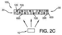
図2c〜図2dは、1つのルミネセンス材料が別のものよりも速く劣化する状況を概略的に示す。ルミネセンス材料20は、1つ又は複数のより速く劣化する有機ルミネセンス材料720と、1つ又は複数のより遅く劣化するルミネセンス材料820とを備える。1つ又は複数のより速く劣化する有機ルミネセンス材料720は、1つ又は複数のより遅く劣化する有機ルミネセンス材料820よりも速く劣化する。例として、図2cは、埋め込まれたルミネセンス材料を示し、図2dは、層状にされた構成を示す。これらの図面では、より速く劣化するルミネセンス材料が斜線で示されている。単に理解しやすくするために、第1の有機ルミネセンス材料120は、より速く劣化するルミネセンス材料720として示され、第2の有機ルミネセンス材料220は、より遅く劣化するルミネセンス材料820として示されている。しかし、これは逆でもよい。更に、3つ以上の有機ルミネセンス材料が存在してもよい。したがって、図2c〜図2dは、後述の幾つかの実施形態を理解するための手引きにすぎない。
Figures 2c-2d schematically illustrate the situation where one luminescent material degrades faster than another. The
図3a〜図3gに、本発明の幾つかの実施形態、及び本発明に関係する幾つかの更なる態様を概略的に示す。図2c〜図2d及び図3a〜図3gは、照明デバイス100の幾つかの実施形態を概略的に示し、ここで、ルミネセンス材料20は、1つ又は複数のより速く劣化する有機ルミネセンス材料720(例えば第1の有機ルミネセンス材料120)と、1つ又は複数のより遅く劣化する有機ルミネセンス材料820(例えば第2の有機ルミネセンス材料220)とを備え、1つ又は複数のより速く劣化する有機ルミネセンス材料720が、1つ又は複数のより遅く劣化する有機ルミネセンス材料820よりも速く劣化する。
Figures 3a-3g schematically illustrate some embodiments of the present invention and some further aspects related to the present invention. Figures 2c-2d and 3a-3g schematically illustrate some embodiments of the
図3aは、照明デバイス100の一実施形態を概略的に示し、ここでは、ルミネセンス材料20が、層130内に構成された第1の有機ルミネセンス材料120と、層140内に構成された第2の有機ルミネセンス材料220とを備える。第1の有機ルミネセンス材料120は、第1のホスト材料51内に埋め込まれる。第2の有機ルミネセンス材料220は、第2のホスト材料52内に埋め込まれる。第1の有機ルミネセンス材料120は、保護されていない状態では、第2の有機ルミネセンス材料22に比べて高い劣化速度を有し、この劣化速度の差を少なくとも一部補償するために、第1の有機ルミネセンス材料120及び第2の有機ルミネセンス材料220は、それぞれ第1のホスト材料51及び第2のホスト材料52内に埋め込まれる。このようにして、より速く劣化する有機ルミネセンス材料720は、第1のホスト材料51内に埋め込まれ、より遅く劣化する有機ルミネセンス材料820は、第2のホスト材料52内に埋め込まれる。第1のホスト材料51は、第1の有機ルミネセンス材料120がさらされる酸素及び/又は水の量を減少させることによって、第1の有機材料120の劣化速度を減少させる。一実施形態では、ホスト材料51とホスト材料52は、第1の有機ルミネセンス材料120と第2の有機ルミネセンス材料220の劣化速度の差を補償するように化学的に異なる。
FIG. 3 a schematically illustrates one embodiment of a
図3bは、1つ又は複数のより速く劣化する有機ルミネセンス材料720、例えば第1の有機ルミネセンス材料120が、1つ又は複数のより遅く劣化する有機ルミネセンス材料820、例えば第2の有機ルミネセンス材料220よりも低い光源光強度にさらされるように構成される一実施形態を概略的に示す。これは、より速く劣化するルミネセンス材料720を、光源から距離d2で層130内に配置し、より遅く劣化する有機ルミネセンス材料820を、光源から距離d1で層140内に配置すること(d1<d2)によって行われ、及び/又は、より速く劣化する有機ルミネセンス材料720をより遅く劣化する有機ルミネセンス材料820よりも下流に配置することによって行われる。ここで、この概略図面では、両方の選択肢が同時に適用される。任意選択的に、ルミネセンス材料の位置は相互交換されてもよい。
FIG. 3b shows that one or more faster-degrading organic
図3cは、ルミネセンス材料20の1つ又は複数が、層130内に構成されたそのような第1のホスト材料51内に埋め込まれ、ルミネセンス材料20の1つ又は複数が、層140内に構成されたそのような第2のホスト材料52内に埋め込まれ、第1のホスト材料51又は層130が、酸素バリア151によって取り囲まれる一実施形態を概略的に示す。これは、第1のホスト材料内の比較的速く劣化する第1の有機ルミネセンス材料120の全体的な劣化速度を減少させることがある。しかし、色点のシフトに応じて、配置が異なることもある。したがって、更なる実施形態(図示せず)では、ルミネセンス材料20の1つ又は複数がそのような第2のホスト材料52内に埋め込まれ、ルミネセンス材料20の1つ又は複数がそのような第1のホスト材料51内に埋め込まれ、第2のホスト材料52が酸素バリアによって取り囲まれる。
FIG. 3 c shows that one or more of the
図3dは、1つ又は複数のより速く劣化する有機ルミネセンス材料720が、第1の層1020の上流面1121と下流面1122との間で第1の層厚さL1を有する第1の層1020内に構成され、前記第1の層1020内のそれらの1つ又は複数のより速く劣化する有機ルミネセンス材料が、光源光と、他のルミネセンス材料20の1つ又は複数によって発生される光とからなる群から選択される励起光111によって励起可能である一実施形態を概略的に示す。照明デバイス100の動作中、励起光111は、上流面1121から下流面1122に向かう方向に進んでいる。第1の層厚さL1(及び適用可能な場合には濃度)は、励起光の波長範囲の少なくとも一部に関して、前記波長範囲部分の全ての光が、下流面1122に到達する前に1つ又は複数のより速く劣化する有機ルミネセンス材料720によって吸収されることを課すように選択される。
FIG. 3 d shows a first layer in which one or more faster degrading organic
更に、この概略図面はまた、第2の層1220の上流面1221と下流面1222との間で第2の層厚さL2を有する第2の層1220内に構成された1つ又は複数のより遅く劣化する有機ルミネセンス材料820を示し、前記第2の層1220内のそれらの1つ又は複数のより遅く劣化する有機ルミネセンス材料は、光源光と、他のルミネセンス材料20の1つ又は複数によって発生される光とからなる群から選択される励起光111によって励起可能である。照明デバイス100の動作中、励起光111は、上流面1221から下流面1222に向かう方向に進んでいる。第2の層厚さL2(及び適用可能な場合には濃度)は、励起光の波長範囲の少なくとも一部に関して、前記波長範囲部分の光の一部のみが、下流面1222に到達するまでに1つ又は複数のより遅く劣化する有機ルミネセンス材料820によって吸収されることを課すように選択される。
Further, this schematic drawing also shows one or more twists configured in the
したがって、第1の層内で、より速く劣化する有機ルミネセンス材料720による励起光の完全な変換が行われる。しかし、第2の層内では、より遅く劣化する有機ルミネセンス材料820による励起光の一部の変換のみが行われる。時間と共に、ブリーチングが生じることがあり、それにより、励起光は、第1の層内により深く浸透され得る。これは、図3eに示されており、図3eにおいて、長方形が層を概略的に示すが、y軸上に、層内への深さx(x軸)の関数としての励起光の強度が示されている。下流面1122に到達する前に、全ての励起光が吸収されている。時間と共に、励起光が見つからなくなる前線が、下流面に向けてシフトする。このようにして、より遅い劣化の影響、したがってより遅い色点シフトが実現され得る。
Thus, complete conversion of the excitation light by the organic
同じ効果は、代替又は追加としてルミネセンス材料の濃度を増加又は減少させることによって得られることがあり、濃度が大きくなるにつれて、吸収性がより高くなり、層内の励起光の経路長が減少することがあり、濃度が小さくなるにつれて、吸収性がより低くなり、層内の励起光の経路長が増加することがある。 The same effect may be obtained by increasing or decreasing the concentration of the luminescent material as an alternative or in addition, as the concentration increases, the absorption becomes higher and the path length of the excitation light in the layer decreases. In some cases, as the concentration decreases, the absorption is lower and the path length of the excitation light in the layer may increase.
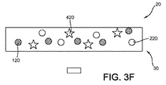
図3fは、更に1つ又は複数の無機ルミネセンス材料420が適用される一実施形態を概略的に示す。無機ルミネセンス材料420の1つ又は複数は、第1又は第2のルミネセンス材料120、200の発光波長範囲の少なくとも一部で、特に、最も速く劣化する有機ルミネセンス材料の発光波長範囲の少なくとも一部で発光するように構成される。したがって、図3fでは、より速く劣化する有機ルミネセンス材料720の1つ又は複数が、動作中に第1の所定の波長範囲内で発光する。ルミネセンス材料20は、更に、1つ又は複数のより速く劣化する有機ルミネセンス材料720よりも遅く劣化するように構成された1つ又は複数の無機ルミネセンス材料420を備える。前記1つ又は複数の無機ルミネセンス材料420は、動作中に、第2の所定の波長範囲内で発光し、この範囲は、第1の所定の波長範囲と少なくとも一部重なる。このようにすると、より速く劣化する有機ルミネセンス材料に近い色点を有する発光を有する無機ルミネセンス材料によって、より速く劣化する有機ルミネセンス材料の色点シフトが全体の色点(シフト)に及ぼす影響が減少される。
FIG. 3f schematically illustrates one embodiment in which one or more inorganic
図3gは、1つのグラフに、2つの有機ルミネセンス材料の吸収(励起)及び発光を概略的に示す。照明デバイスの動作中、1つ又は複数のより速く劣化する有機ルミネセンス材料は、1つ又は複数のより遅く劣化する有機ルミネセンス材料によって発生される光によって少なくとも一部励起されるように構成される。より速く劣化する有機ルミネセンス材料の吸収が参照符号A1で示され、より遅く劣化する有機ルミネセンス材料の吸収が参照符号A2で示され、より速く劣化する有機ルミネセンス材料の発光が参照符号EM1で示され、これはA2と重なり、より遅く劣化する有機ルミネセンス材料の発光が参照符号EM2で示される。ここで、より遅く劣化するルミネセンス材料(特にその吸収A2)は、(それが、より速く劣化する有機ルミネセンス材料からの発光EM1を吸収するので)より速く劣化する有機ルミネセンス材料に放射的に結合される。 FIG. 3g schematically shows the absorption (excitation) and emission of two organic luminescent materials in one graph. During operation of the lighting device, the one or more faster-degrading organic luminescent materials are configured to be at least partially excited by light generated by the one or more slower-degrading organic luminescent materials. The The absorption of the faster-degrading organic luminescent material is indicated by reference A1, the absorption of the slower-degrading organic luminescent material is indicated by reference A2, and the emission of the faster-degrading organic luminescent material is indicated by reference EM1. This overlaps with A2 and the emission of the slower organic luminescent material is indicated by reference numeral EM2. Here, the slower degrading luminescent material (especially its absorption A2) is radiated to the faster degrading organic luminescent material (since it absorbs the luminescent EM1 from the faster degrading organic luminescent material). Combined with
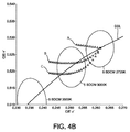
図4a〜図4bは、実験的証拠を示す。図4aは、図3a〜図3fに示される実施形態の1つによる、青色LEDと、F305 red、F240 orange、及びF083 yellowの組合せとの色点を示す。参照符号aは、そのような混合物の8つの層(即ち、それら8層の各層が、これら3つのルミネセンス材料の同一の混合物を備える)を表し;参照符号bは、そのような混合物の7つの層を表し、参照符号cは、この混合物の6つの層を表し、参照符号dは、そのような混合物の5つの層を表し、参照符号eは、この混合物の4つの層を表す。これは、1層ずつ除去されているので、ブリーチングのシミュレーションである(全ての有機ルミネセンス材料が同じ速度で劣化する)。色点は、完全にBBLの上をシフトし、したがって白色に留まる。図4bは、青色LEDと、YAG:Ce、並びに有機赤色(曲線A)、有機黄色(少量)と有機赤色(曲線B)、及び有機黄色(多量)と有機赤色(曲線C)の組合せとの色点シフトの結果を示す。黄色有機ルミネセンス材料の劣化速度は、有機赤色ルミネセンス材料の劣化の10倍速いと仮定された。F305(曲線A)、即ち赤色成分のみを使用すると、色点がBBLから離れすぎた位置に達するまでに、わずか約15%の劣化しか許されなかった。しかし、後の2つの場合(本発明によれば、曲線B及びC)には、色点がオフホワイトになりすぎるまでに、45%の劣化が生じてよい。これは、寿命を約3倍延長させることができる。これらは、まだ最適ではないシステムの例である。したがって、本願で特許請求する技術を用いて、寿命をより延ばすことが十分に可能になり得る。 Figures 4a-4b show experimental evidence. FIG. 4a shows the color points of a blue LED and a combination of F305 red, F240 orange, and F083 yellow according to one of the embodiments shown in FIGS. 3a-3f. The reference a represents the eight layers of such a mixture (i.e. each of the eight layers comprises the same mixture of these three luminescent materials); the reference b represents 7 of such a mixture. Reference numeral c represents six layers of this mixture, reference numeral d represents five layers of such a mixture, and reference numeral e represents four layers of this mixture. This is a simulation of bleaching because one layer is removed at a time (all organic luminescent materials degrade at the same rate). The color point shifts completely over the BBL and therefore remains white. FIG. 4b shows a combination of a blue LED, YAG: Ce, and organic red (curve A), organic yellow (small amount) and organic red (curve B), and a combination of organic yellow (large amount) and organic red (curve C). The result of the color point shift is shown. It was assumed that the degradation rate of the yellow organic luminescent material was 10 times faster than the degradation of the organic red luminescent material. Using only F305 (curve A), the red component, only about 15% degradation was allowed before the color point reached a position too far from the BBL. However, in the latter two cases (according to the invention, curves B and C), 45% degradation may occur before the color point becomes too white. This can extend the life by about 3 times. These are examples of systems that are not yet optimal. Thus, it may be possible to further extend the life using the technology claimed in this application.
図5a〜図5bは、更なる実験的証拠を示す図である。図5aは、図3a〜図3fの実施形態の1つによる、青色LEDと、有機赤色(Lumogen F305)及び有機緑色/黄色蛍光体(Lumogen 850)の組合せとの色点の変化を示す。保護されていない状態での有機緑色/黄色蛍光体は、保護されていない状態の有機赤色蛍光体に比べて高い劣化速度を有する。有機緑色/黄色蛍光体が配置される層130の構成がLEDデバイスの寿命に及ぼす効果が、シミュレーションによって示される。これらのシミュレーションでは、有機赤色ルミネセンス材料(DR2)の劣化速度に対する緑色/黄色有機ルミネセンス材料(DR1)の劣化速度が変えられた。即ち、DR1=4*DR2(曲線A)、DR1=2*DR2(曲線B)、DR1=DR2(曲線C)、及びDR1=(1/2)*DR2(曲線D)である。緑色/黄色ルミネセンス材料の劣化速度は、論じられる一実施形態又は実施形態の組合せ、例えば緑色/黄色有機ルミネセンス材料に関する酸素バリア及び/又は異なるマトリックス材料の使用によって、赤色有機ルミネセンス材料に対して減少され得る。代替として、図3dに示されるような構成に関して、第1の層厚さL1が増加されてもよく、及び/又は第1の層1020内のより速く劣化する有機ルミネセンス材料720の濃度が増加されてもよい。緑色/黄色有機ルミネセンス材料の比較的高い劣化速度(曲線A)では、色点は、時間にわたって、よりピンク色に向かって比較的速く変化する。劣化速度が減少すると(曲線Aから曲線Bへ、更に曲線Cへ移動すると)、BBLから離れる色点のシフトは比較的遅くなり、色点がBBLから離れすぎた位置に達するまでの時間が延び、即ちLEDデバイスの寿命が延びる。曲線Dは、緑色/黄色有機ルミネセンス材料によって青色LEDの励起光の少なくとも一部の完全な変換が行われる状況を表し(図3e及び対応する説明も参照のこと)、これは、BBLに沿ってシフトして比較的長い期間にわたって白色に留まる色点を生じる。図5bは、更に、有機赤色ルミネセンス材料(DR2)の劣化速度に対する緑色/黄色有機ルミネセンス材料(DR1)の劣化速度の減少、即ちDR2/DR1の値の増加が、照明デバイスの寿命に及ぼす効果を示す(破線)。y軸上で、符号LFは、LEDデバイスの寿命、即ち色点がBBLから離れすぎた位置に達するまでの期間の相対値を表す。x軸上で、符号ODは、光学密度(OD=−LOG(T)、ここで、Tは透過率を表す)を表し、ODは、緑色/黄色有機ルミネセンス材料の濃度に関する測定量であり、例えば図3dによる実施形態では、第1の層1020内のより速く劣化する有機ルミネセンス材料720の濃度を増加させることによって測定される。ODの値0.1に関して、LFの相対値は、1に設定される。OD値が増加すると、LEDデバイスの寿命が延び、LEDデバイスの寿命は、ODの値1.2で、10倍に増加される(LF=10)。ODの値を増加させると、緑色/黄色ルミネセンス材料の劣化が更に補償され、特定のOD値で、緑色/黄色有機ルミネセンス材料によって励起光の少なくとも一部の完全な変換が行われる状況に達し(図3e及び対応する説明も参照のこと)、これが、BBLに沿ってシフトして比較的長い期間にわたって白色に留まる色点を生じることによって、寿命の延長が説明され得る。記号(●及び□)によって示される実験値は、シミュレーション(破線)に一致する。
Figures 5a to 5b show further experimental evidence. FIG. 5a shows the change in color point between a blue LED and an organic red (Lumogen F305) and organic green / yellow phosphor (Lumogen 850) combination according to one of the embodiments of FIGS. 3a-3f. The organic green / yellow phosphor in the unprotected state has a higher degradation rate than the organic red phosphor in the unprotected state. The effect of the configuration of the
Claims (15)
Applications Claiming Priority (3)
| Application Number | Priority Date | Filing Date | Title |
|---|---|---|---|
| EP20120161965 EP2645822A1 (en) | 2012-03-29 | 2012-03-29 | Lighting device comprising at least two organic luminescent materials |
| EP12161965.4 | 2012-03-29 | ||
| PCT/IB2013/052277 WO2013144795A1 (en) | 2012-03-29 | 2013-03-22 | Lighting device comprising at least two organic luminescent materials. |
Publications (2)
| Publication Number | Publication Date |
|---|---|
| JP2015518630A true JP2015518630A (en) | 2015-07-02 |
| JP2015518630A5 JP2015518630A5 (en) | 2016-05-12 |
Family
ID=48325813
Family Applications (1)
| Application Number | Title | Priority Date | Filing Date |
|---|---|---|---|
| JP2015502502A Ceased JP2015518630A (en) | 2012-03-29 | 2013-03-22 | Lighting device comprising at least two organic luminescent materials |
Country Status (5)
| Country | Link |
|---|---|
| US (1) | US9157583B2 (en) |
| EP (2) | EP2645822A1 (en) |
| JP (1) | JP2015518630A (en) |
| CN (1) | CN104206018A (en) |
| WO (1) | WO2013144795A1 (en) |
Families Citing this family (7)
| Publication number | Priority date | Publication date | Assignee | Title |
|---|---|---|---|---|
| JP6285908B2 (en) * | 2012-04-13 | 2018-02-28 | コーニンクレッカ フィリップス エヌ ヴェKoninklijke Philips N.V. | Light conversion assembly, lamp and luminaire |
| WO2015062916A1 (en) * | 2013-11-01 | 2015-05-07 | Koninklijke Philips N.V. | New class of green/yellow emitting phosphors based on derivatives of benzimidazoxanthenoisoquinolinone for led lighting |
| CN105301878B (en) * | 2014-07-17 | 2018-04-13 | 深圳市光峰光电技术有限公司 | Wavelength converter and preparation method thereof, related lighting fixtures and optical projection system |
| WO2016062657A1 (en) | 2014-10-21 | 2016-04-28 | Philips Lighting Holding B.V. | New class of organic phosphors based on derivatives of benzimidazoxanthenoisoquinolinone for led lighting |
| JP6628056B2 (en) | 2015-01-31 | 2020-01-08 | エルジー・ケム・リミテッド | Light conversion element and display device including the same |
| CN107544178A (en) * | 2016-06-29 | 2018-01-05 | 株式会社Lg化学 | Light conversion element and the display device for including it |
| KR102334956B1 (en) * | 2018-11-01 | 2021-12-02 | 주식회사 엘지화학 | Ramp for vehicle and manufacturing method of same |
Citations (9)
| Publication number | Priority date | Publication date | Assignee | Title |
|---|---|---|---|---|
| JP2002374006A (en) * | 2001-06-15 | 2002-12-26 | Toyoda Gosei Co Ltd | Light-emitting apparatus |
| JP2006135225A (en) * | 2004-11-09 | 2006-05-25 | Toshiba Corp | Light-emitting device |
| JP2006279007A (en) * | 2005-03-02 | 2006-10-12 | Konica Minolta Holdings Inc | Organic electroluminescent element, display device, and lighting device |
| JP2008258171A (en) * | 2008-05-07 | 2008-10-23 | Shizuo Fujita | Planar light-emitting device |
| JP2011509427A (en) * | 2008-01-03 | 2011-03-24 | コーニンクレッカ フィリップス エレクトロニクス エヌ ヴィ | Display device and lighting device |
| US20110241044A1 (en) * | 2010-03-31 | 2011-10-06 | Samsung Electronics Co., Ltd. | Liquid crystal display device including white light emitting diode |
| JP2011528490A (en) * | 2008-02-27 | 2011-11-17 | コーニンクレッカ フィリップス エレクトロニクス エヌ ヴィ | Lighting device comprising an LED and one or more transmissive windows |
| JP2012009639A (en) * | 2010-06-25 | 2012-01-12 | Panasonic Electric Works Co Ltd | Light-emitting device |
| US20120007494A1 (en) * | 2010-07-09 | 2012-01-12 | Nitto Denko Corporation | Phosphor composition and light emitting device using the same |
Family Cites Families (8)
| Publication number | Priority date | Publication date | Assignee | Title |
|---|---|---|---|---|
| US20060066234A1 (en) * | 2004-09-29 | 2006-03-30 | Chun-Chung Lu | Organic electro-luminescent display panel and method of fabricating the same |
| JPWO2006092943A1 (en) | 2005-03-02 | 2008-08-07 | コニカミノルタホールディングス株式会社 | Organic electroluminescence element, display device and lighting device |
| US8053765B2 (en) | 2005-11-09 | 2011-11-08 | Konica Minolta Holdings, Inc. | Organic electroluminescent element, display device and lighting device |
| US20090104130A1 (en) | 2007-04-16 | 2009-04-23 | Bernstein Eric F | Compositions comprising organic and inorganic phosphors for converting electromagnetic radiation and methods for using the same |
| US9006711B2 (en) | 2007-04-17 | 2015-04-14 | Konica Minolta Holdings, Inc. | White organic electroluminescent element and lighting device |
| US20100141125A1 (en) | 2007-05-16 | 2010-06-10 | Konica Minolta Holdings, Inc. | Organic electroluminescent element, display device and lighting device |
| WO2010106478A1 (en) | 2009-03-19 | 2010-09-23 | Koninklijke Philips Electronics N.V. | Color adjusting arrangement |
| ES2425090T3 (en) | 2009-04-06 | 2013-10-11 | Koninklijke Philips N.V. | Luminescent converter for a phosphor-enhanced light source comprising organic and inorganic matches |
-
2012
- 2012-03-29 EP EP20120161965 patent/EP2645822A1/en not_active Withdrawn
-
2013
- 2013-03-22 CN CN201380015890.7A patent/CN104206018A/en active Pending
- 2013-03-22 EP EP13721096.9A patent/EP2837267A1/en not_active Withdrawn
- 2013-03-22 WO PCT/IB2013/052277 patent/WO2013144795A1/en active Application Filing
- 2013-03-22 JP JP2015502502A patent/JP2015518630A/en not_active Ceased
- 2013-03-22 US US14/388,937 patent/US9157583B2/en not_active Expired - Fee Related
Patent Citations (9)
| Publication number | Priority date | Publication date | Assignee | Title |
|---|---|---|---|---|
| JP2002374006A (en) * | 2001-06-15 | 2002-12-26 | Toyoda Gosei Co Ltd | Light-emitting apparatus |
| JP2006135225A (en) * | 2004-11-09 | 2006-05-25 | Toshiba Corp | Light-emitting device |
| JP2006279007A (en) * | 2005-03-02 | 2006-10-12 | Konica Minolta Holdings Inc | Organic electroluminescent element, display device, and lighting device |
| JP2011509427A (en) * | 2008-01-03 | 2011-03-24 | コーニンクレッカ フィリップス エレクトロニクス エヌ ヴィ | Display device and lighting device |
| JP2011528490A (en) * | 2008-02-27 | 2011-11-17 | コーニンクレッカ フィリップス エレクトロニクス エヌ ヴィ | Lighting device comprising an LED and one or more transmissive windows |
| JP2008258171A (en) * | 2008-05-07 | 2008-10-23 | Shizuo Fujita | Planar light-emitting device |
| US20110241044A1 (en) * | 2010-03-31 | 2011-10-06 | Samsung Electronics Co., Ltd. | Liquid crystal display device including white light emitting diode |
| JP2012009639A (en) * | 2010-06-25 | 2012-01-12 | Panasonic Electric Works Co Ltd | Light-emitting device |
| US20120007494A1 (en) * | 2010-07-09 | 2012-01-12 | Nitto Denko Corporation | Phosphor composition and light emitting device using the same |
Also Published As
| Publication number | Publication date |
|---|---|
| US9157583B2 (en) | 2015-10-13 |
| EP2645822A1 (en) | 2013-10-02 |
| CN104206018A (en) | 2014-12-10 |
| EP2837267A1 (en) | 2015-02-18 |
| US20150054401A1 (en) | 2015-02-26 |
| WO2013144795A1 (en) | 2013-10-03 |
Similar Documents
| Publication | Publication Date | Title |
|---|---|---|
| JP6178789B2 (en) | Optical converter and lighting unit having the optical converter | |
| JP6306264B2 (en) | PC-LED module with improved white rendering and conversion efficiency | |
| JP2015518630A (en) | Lighting device comprising at least two organic luminescent materials | |
| US7821188B2 (en) | Lighting device and display device provided with the same | |
| US9877370B2 (en) | Lighting device comprising at least two sets of LEDs | |
| TWI400818B (en) | A light source | |
| KR101955188B1 (en) | Illumination device | |
| EP2835036B1 (en) | A light emitting assembly, a lamp and a luminaire | |
| JP2009206459A (en) | Color conversion member and light-emitting apparatus using the same | |
| EP2950704B1 (en) | A light source, luminaire and surgical illumination unit | |
| JP2017536694A (en) | Fluorescent LED using temperature stable flux and saturated red point | |
| JP2015130459A (en) | Phosphor-containing multilayer film sheet and light-emitting device | |
| JP5548118B2 (en) | Illumination device and liquid crystal display device | |
| US20140191273A1 (en) | Light-emitting arrangement | |
| KR101676291B1 (en) | White organic light-emitting device including light conversion layer and preparing method of the same | |
| EP2548235B1 (en) | Lighting apparatus | |
| EP3999908B1 (en) | Laser phosphor based light source with improved brightness |
Legal Events
| Date | Code | Title | Description |
|---|---|---|---|
| A521 | Request for written amendment filed |
Free format text: JAPANESE INTERMEDIATE CODE: A523 Effective date: 20160316 |
|
| A621 | Written request for application examination |
Free format text: JAPANESE INTERMEDIATE CODE: A621 Effective date: 20160316 |
|
| A711 | Notification of change in applicant |
Free format text: JAPANESE INTERMEDIATE CODE: A711 Effective date: 20160912 |
|
| A977 | Report on retrieval |
Free format text: JAPANESE INTERMEDIATE CODE: A971007 Effective date: 20170123 |
|
| A01 | Written decision to grant a patent or to grant a registration (utility model) |
Free format text: JAPANESE INTERMEDIATE CODE: A01 Effective date: 20170202 |
|
| A045 | Written measure of dismissal of application [lapsed due to lack of payment] |
Free format text: JAPANESE INTERMEDIATE CODE: A045 Effective date: 20170628 |