JP2015517954A - Watercraft fins - Google Patents
Watercraft fins Download PDFInfo
- Publication number
- JP2015517954A JP2015517954A JP2015514285A JP2015514285A JP2015517954A JP 2015517954 A JP2015517954 A JP 2015517954A JP 2015514285 A JP2015514285 A JP 2015514285A JP 2015514285 A JP2015514285 A JP 2015514285A JP 2015517954 A JP2015517954 A JP 2015517954A
- Authority
- JP
- Japan
- Prior art keywords
- fin
- dimples
- dimple
- fins
- foil
- Prior art date
- Legal status (The legal status is an assumption and is not a legal conclusion. Google has not performed a legal analysis and makes no representation as to the accuracy of the status listed.)
- Pending
Links
Images


Classifications
-
- B—PERFORMING OPERATIONS; TRANSPORTING
- B63—SHIPS OR OTHER WATERBORNE VESSELS; RELATED EQUIPMENT
- B63B—SHIPS OR OTHER WATERBORNE VESSELS; EQUIPMENT FOR SHIPPING
- B63B32/00—Water sports boards; Accessories therefor
- B63B32/60—Board appendages, e.g. fins, hydrofoils or centre boards
Landscapes
- Chemical & Material Sciences (AREA)
- Engineering & Computer Science (AREA)
- Combustion & Propulsion (AREA)
- Mechanical Engineering (AREA)
- Ocean & Marine Engineering (AREA)
- Laminated Bodies (AREA)
- Filling Or Discharging Of Gas Storage Vessels (AREA)
- Details Of Rigid Or Semi-Rigid Containers (AREA)
- Table Devices Or Equipment (AREA)
- Physical Water Treatments (AREA)
Abstract
【課題】フィンによって引き起こされる抗力の低減を可能とする。【解決手段】一態様において、本発明は、第1の側面および第2の側面を備えるウォータークラフトのフィンであって、第1の側面または第2の側面の少なくとも一方に複数のディンプルが形成されている、ウォータークラフトのフィンを提供する。【選択図】図5A drag generated by a fin can be reduced. In one aspect, the present invention is a watercraft fin comprising a first side and a second side, wherein a plurality of dimples are formed on at least one of the first side or the second side. Provide watercraft fins. [Selection] Figure 5
Description
本発明は、ウォータークラフト用のフィン、特にサーフボード用のフィンに関する。 The present invention relates to a fin for a watercraft, particularly a fin for a surfboard.
ウォータークラフト、特にサーフボードの重要な部分が、1つまたは複数のフィンである。フィンは、使用者または乗り手が、ボードまたはウォータークラフトに乗り、制御し、楽しみやすくするスタビライザとして働く。最新のサーブボードには、3つや4つのフィンが配置されている。「Thruster」および「Quads」として知られているこれらの3つや4つのフィンを用いる設計は、波面に対するホールドを維持しつつ推進力を作り出すことができる。推進力は、ターン中にサイドフィンによって作られる外向きの力から生成される。 An important part of watercraft, especially surfboards, is one or more fins. The fins act as a stabilizer that allows the user or rider to ride, control and enjoy the board or watercraft. The latest serve board has 3 or 4 fins. Designs using these three or four fins, known as “Thruster” and “Quads”, can create propulsion while maintaining hold on the wavefront. Propulsion is generated from the outward force created by the side fins during the turn.
サイドフィン(左右)は航空機の翼と同様の原理で作用する。流体は、流体がフィンの上を移動するときに、流体がフィンの平坦な内側フォイル面(flat inside foil face)上で動くよりも、湾曲したフォイル面(curved foil face)の上でより速く動く。これにより、平坦面上が高圧になり、湾曲面上が低圧になる。高圧はフォイルを上方に押している。これが飛行機の翼に揚力を作り出す。サーフボードフィンの場合は高圧がフォイル/フィンを外方に押している。フィン上に外側に向けて作り出される揚力は、「ドライブ(drive)」として知られるターンするときにサーファが感じる「感触(feel)」である。この感触は、フィンがもたらすことができる制御、速度および操縦性(manoeuvrability)の大きさに基づいている。ドライブは、サーフボードがターンしているときに活性化され、フィンを横切る迎え角(流れ)は、フィンが揚力を作り出すようにする。この外向きの力(揚力)を増大させることができると、この力(揚力)はフィンが有するドライブの大きさを増大させる。 Side fins (left and right) work on the same principle as aircraft wings. The fluid moves faster on the curved foil face than the fluid moves on the flat inside foil face of the fin as the fluid moves over the fin . As a result, the flat surface has a high pressure and the curved surface has a low pressure. The high pressure pushes the foil upward. This creates lift on the wings of the plane. For surfboard fins, high pressure pushes the foil / fin outward. The lift created outward on the fins is the “feel” felt by the surfer when making a turn, known as “drive”. This feel is based on the amount of control, speed, and maneuverability that the fins can provide. The drive is activated when the surfboard is turning and the angle of attack (flow) across the fin causes the fin to create lift. If this outward force (lift) can be increased, this force (lift) increases the size of the drive the fin has.
この揚力の増大は、抗力を最小限に抑えようと試みるフィン設計者にとって依然として大きな目標であることに変わりはない。速度が増加しても、制御および操縦性を犠牲にしないことが望ましい。一例として、サーフボードの場合、サーファが小さければ必要な揚力はより小さくなるので、乗り手が軽くなると、より小さいフィンを使用することができる。フィンが小さくなると、フォイルの表面積の縮小により揚力が低下するが、抗力も低下する。フォイルの形状は、揚力と抗力との間のトレードオフに基づき設計する。 This increase in lift remains a major goal for fin designers who attempt to minimize drag. It is desirable not to sacrifice control and maneuverability as speed increases. As an example, in the case of a surfboard, the smaller the surfers, the less lift is required, so smaller fins can be used when the rider is lighter. As the fins become smaller, the lift decreases due to the reduction in the surface area of the foil, but the drag also decreases. The shape of the foil is designed based on the trade-off between lift and drag.
フィンの設計を改良するために長年にわたって様々な試みが行われている。概して言えば、これらの試みは失敗しており、当初の設計と大差のない従来の設計基準を補強する働きをしているにすぎない。そのような失敗はまた、当業界を、標準設計を変えようとする試みを極めて重要なものにしている。 Various attempts have been made over the years to improve the fin design. Generally speaking, these attempts have failed and only serve to reinforce traditional design standards that are not significantly different from the original design. Such failures also make the industry extremely important to attempt to change the standard design.
フィンの設計が重要であることに変わりはないが、フィンの実際の構造も非常に重要である。例えば、抗力を最小限に抑えるために、フィンの表面は、フィンと水との間の摩擦を低減するようにできるだけ滑らかにすることが重要であることが理解されよう。摩擦は、フィンが水中を滑らかに滑走できるようするために、できるだけ低減される必要があることが分かっている。 The fin design is still important, but the actual structure of the fin is also very important. For example, it will be appreciated that to minimize drag, it is important that the surface of the fin be as smooth as possible so as to reduce friction between the fin and water. It has been found that the friction needs to be reduced as much as possible to allow the fins to slide smoothly in the water.
これらの努力にもかかわらず、ファンの設計において抗力は問題となっていて、したがって、本発明は、フィンによって引き起こされる抗力を低減しようとするものである。 Despite these efforts, drag is a problem in fan design, and therefore the present invention seeks to reduce the drag caused by the fins.
幅広い形で、サーフボードまたは他のウォータークラフト用のフィンが提供されているフィンの表面には、フィンの性能を向上させる複数のディンプル(dimples)が形成されている。ディンプルは、表面上の小さい凹部または凹凸部のようなものである。一態様において、本発明は、第1の側面および第2の側面を備えたウォータークラフトのフィンであって、第1の側面または第2の側面の少なくとも一方に複数のディンプルが形成された、ウォータークラフトのフィンを提供する。「2つの側面」への言及は、フィンの2つの主要面を意味すると理解される。従来のフィンでは、サイドフィンの場合、一方の側面が実質的に平坦であり、他方の側面が湾曲している。これらの側面は、航空機の翼の上部および下部に例えることができる。 In a wide variety of forms, surfboards or other watercraft fins are provided on the surface of the fins with a plurality of dimples that improve the performance of the fins. The dimple is like a small concave or convex portion on the surface. In one aspect, the present invention is a watercraft fin having a first side and a second side, wherein a plurality of dimples are formed on at least one of the first side or the second side. Provide craft fins. Reference to “two sides” is understood to mean the two main sides of the fin. In the conventional fin, in the case of a side fin, one side surface is substantially flat and the other side surface is curved. These aspects can be compared to the upper and lower parts of an aircraft wing.
好ましい構成では、ディンプルは実質的に円形であり、2.0mm〜4.5mmの直径および0.1mm〜0.5mmの深さを有する。理想的には、直径は3.8mm〜4.3mmであり、深さは0.2mm〜0.5mmである。 In a preferred configuration, the dimples are substantially circular and have a diameter of 2.0 mm to 4.5 mm and a depth of 0.1 mm to 0.5 mm. Ideally, the diameter is between 3.8 mm and 4.3 mm and the depth is between 0.2 mm and 0.5 mm.
ディンプルの間隔もまた本発明にとって重要である。隣り合うディンプル間の中心点は互いに3.7mm〜4.5mm離れていることが必要であり、中心点はディンプルの中心と見なされ、隣り合うディンプルは、互いに近接してかつ他のディンプルが間に配置されていない状態で配置される2つのディンプルを意味する。 The dimple spacing is also important for the present invention. The center points between adjacent dimples must be separated from each other by 3.7 mm to 4.5 mm, the center point is regarded as the center of the dimple, and the adjacent dimples are close to each other and between other dimples Means two dimples arranged in a state where they are not arranged.
理想的には、フォイルの形状を変形させたりフィンの曲げ特性を低下させたりしないように、ディンプル相互間に所定の間隔が設けられている。隣り合うディンプルの縁部は、互いに0.2mm〜0.5mm離れて配置されてもよい。好ましい構成では、隣り合う縁部間の距離は0.3mm〜0.4mmである。 Ideally, a predetermined interval is provided between the dimples so as not to deform the shape of the foil or deteriorate the bending characteristics of the fin. The edges of the adjacent dimples may be arranged 0.2 mm to 0.5 mm apart from each other. In a preferred configuration, the distance between adjacent edges is 0.3 mm to 0.4 mm.
ディンプルが列をなして配置されてもよい。いくつかの実施形態では、これらの列は、フィンのベース、すなわちウォータークラフトの面に対して実質的に平行になる。フィンのベースは、ウォータークラフトと一体化された、またはウォータークラフトに装着されたフィンの一部であり、反対側の端部はフィンの先端部である。他の実施形態では、これらの列は、フィンのベースに対して170度〜190度の角度、すなわち平行から±10度の角度となるように設けられている。 The dimples may be arranged in a row. In some embodiments, these rows are substantially parallel to the base of the fin, i.e., the surface of the watercraft. The base of the fin is a part of the fin integrated with or attached to the watercraft, and the opposite end is the tip of the fin. In other embodiments, these rows are provided at an angle of 170-190 degrees with respect to the base of the fin, ie, an angle of ± 10 degrees from parallel.
いくつかの実施形態では、実質的にフィンの側面全体にディンプルが形成される。別の構成では、ディンプルは、フィンの最も広い箇所からフィンの後方縁部にかけて配置される。 In some embodiments, dimples are formed substantially across the sides of the fin. In another configuration, the dimples are arranged from the widest part of the fin to the rear edge of the fin.
ディンプルは、要求される性能に応じて、フィンの両側に配置されてもよく、あるいは片側のみに限定して配置されてもよい。 The dimples may be arranged on both sides of the fin according to required performance, or may be arranged only on one side.
ただ1つのディンプル付き側面を有するフィンの場合、揚力発生側にディンプルが形成される必要がある。 In the case of a fin having only one side surface with dimples, it is necessary to form dimples on the lift generation side.
実施に応じて、ディンプルの形状は、円形ではなく、六角形、三角形、長方形、楕円形、または正方形でもよい。更に、いくつかの構成では、異なるディンプルサイズを有するように、すなわち、ディンプルのサイズが前縁から始まりフィンの後縁まで延びる列において増大するように選択してもよい。 Depending on the implementation, the dimple shape may be hexagonal, triangular, rectangular, elliptical, or square rather than circular. Further, in some configurations, one may choose to have different dimple sizes, i.e., the dimple size increases in a row starting from the leading edge and extending to the trailing edge of the fin.
本発明は、現行のフィンの設計に採用されている従来の考えから著しく発展した物である。ディンプルを形成することは、フィンの性能の顕著な向上につながり、それによってフィンが装着されるウォータークラフトの顕著な改善につながる。 The present invention is a significant development from the conventional idea employed in current fin designs. Forming dimples leads to a significant improvement in fin performance, thereby leading to a significant improvement in the watercraft on which the fin is mounted.
本発明の例示的な実施形態について添付図を参照しながら説明する。本発明の他の特徴および利点は、付随する記述からも明らかになるであろう。 Exemplary embodiments of the present invention will be described with reference to the accompanying drawings. Other features and advantages of the invention will be apparent from the accompanying description.
以下の記述は、当業者であれば本発明を製作し使用することができるように提示され、かつ、当該技術は特定の用途と当該用途に必要なものについて示されている。開示される諸実施形態の様々な修正形態が当業者には容易に明らかになり、本明細書に規定される一般的原理は、本発明の精神および範囲から逸脱することなく他の実施形態および応用例に適用されてもよい。本発明は、示される実施形態に限定されるものではなく、本明細書に開示される原理および特徴と一致する最も広い範囲で解釈されるべきである。 The following description is presented to enable one of ordinary skill in the art to make and use the invention, and the art is presented for a particular application and what is required for that application. Various modifications to the disclosed embodiments will be readily apparent to those skilled in the art, and the generic principles defined herein may be used in other embodiments and without departing from the spirit and scope of the invention. You may apply to an application example. The present invention is not limited to the embodiments shown, but is to be construed in the widest scope consistent with the principles and features disclosed herein.
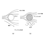
サーフボードなどのウォータークラフトを最適に制御するためには、水の流れがフィンなどの制御面と接触し続けることが望ましい。水流がフォイルの表面から離れると、水流は剥離泡を形成し始める。これは、通常、迎え角が高いときや、急ターン時に起こり、コアンダ効果(Coanda effect)(流水が曲面に付着する傾向)が起こらなくなり、圧力抗力を生成して揚力を減少させ、最終的にはフィンが失速することになるので、望ましくない。すなわち、ウォータークラフトの速度および制御性が低下する。 In order to optimally control a watercraft such as a surfboard, it is desirable for the water flow to remain in contact with a control surface such as a fin. As the water stream leaves the foil surface, the water stream begins to form exfoliation bubbles. This usually occurs when the angle of attack is high or during a sudden turn, and the Coanda effect (the tendency of the running water to adhere to the curved surface) does not occur, generating pressure drag and reducing lift. Is undesirable because the fin will stall. That is, the speed and controllability of the watercraft are reduced.
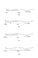
図1aを参照すると、滑らかな物体のまわりの水の層流が示されている。層流は流線形の流れとしても知られており、平行な層状の流体の流れである。流体は、層が混合することなく直線状に流れ続ける。図1aに示されているように、滑らかな形状の物体が流れの中に挿入されると、平行な層は、概して同じ方向に(図の左から右へ)流れ続けるが、各層が大きく剥離する。 Referring to FIG. 1a, a laminar flow of water around a smooth object is shown. Laminar flow, also known as streamlined flow, is a parallel laminar fluid flow. The fluid continues to flow linearly without the layers mixing. As shown in FIG. 1a, when a smooth-shaped object is inserted into the flow, the parallel layers continue to flow in generally the same direction (from left to right in the figure), but each layer is greatly separated. To do.
対照的に、図1bに示されているようにディンプル付き表面が流れの中に挿入されると、ディンプルの効果により、この分離が低減される。表面上のディンプルは乱流を作り出し、乱流は、流れをフォイル/フィンの上に引き戻し、後部の高圧領域からの逆流(流れの剥離分離とも呼ばれる)を妨げる。乱流境界層はより大きなエネルギーを含んでおり、したがって、乱流境界層は、負圧勾配の大きさが大きくなるまで剥離を遅らせ、それによって剥離点をフォイル上のより後部に効果的に移動させ、場合によっては剥離を完全になくす。 In contrast, when a dimpled surface is inserted into the flow as shown in FIG. 1b, the dimple effect reduces this separation. The dimples on the surface create turbulence that pulls the flow back over the foil / fin and prevents backflow (also called flow separation) from the rear high pressure region. The turbulent boundary layer contains more energy, and therefore the turbulent boundary layer delays separation until the magnitude of the negative pressure gradient is increased, thereby effectively moving the separation point to the rear on the foil In some cases, peeling is completely eliminated.
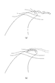
この効果は、フィンの表面上の水流を例示する図2にも見られる。図1aにおける滑らかな物体と同様に、図2aにおけるフィンの滑らかな表面では引力が全く得られず、水とフィンの表面との間を大きく剥離させ得る。その結果、流れはフォイルを削ぎ取ってキャビテーションを作り出し、キャビテーションは操縦または高い迎え角の間にフィンを失速させる。図2bは、フィンの表面上のディンプルの効果を示す。この場合、ディンプルによって生成される乱流が湾曲フォイル表面上を逆流するので、フォイルは、より高い迎え角で機能することが可能になる。 This effect can also be seen in FIG. 2, which illustrates the water flow on the surface of the fin. Similar to the smooth object in FIG. 1a, the smooth surface of the fin in FIG. 2a does not provide any attraction and can cause significant separation between the water and the surface of the fin. As a result, the flow scrapes off the foil to create cavitation, which causes the fins to stall during maneuvering or high angles of attack. FIG. 2b shows the effect of dimples on the surface of the fin. In this case, the turbulence generated by the dimples flows back over the curved foil surface, allowing the foil to function at a higher angle of attack.
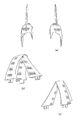
同様に、図3aは、フィンの先端部のまわりに渦が作られるという既知の問題を示す。これらの、フィンの先端渦は誘導抗力に関連しており、フィンに対する不可避な副作用によって揚力が発生する。フィンの先端渦は、後方乱流(wake turbulence)の主成分を形成する。図3aに示されているように、フィンの前に低圧力領域を作ることにより、フィンは空力的揚力を発生させる。流体は、高圧から低圧へ流れるものであり、フィンの後部の流体は、フィン先端部を通ってフィンの上部に向かって移動する傾向がある。流体は、その速度に起因してフィンの前縁の周囲で逃げずに、先端部の周囲を流れることができる。結果として、流体は、フィンの後部から先端部周囲に流れ、フィンの前部まで、環状に流れる。この漏れは、フィンの前部の圧力を上昇させ、フィンが発生させることができる揚力を減少させる。 Similarly, FIG. 3a shows the known problem that a vortex is created around the tip of the fin. These fin tip vortices are associated with induced drag, and lift is generated by inevitable side effects on the fins. The tip vortex of the fin forms the main component of wake turbulence. As shown in FIG. 3a, by creating a low pressure region in front of the fin, the fin generates aerodynamic lift. The fluid flows from high pressure to low pressure, and the fluid at the rear of the fin tends to move through the fin tip toward the top of the fin. The fluid can flow around the tip without escaping around the front edge of the fin due to its velocity. As a result, the fluid flows from the rear of the fin to the periphery of the tip and flows in an annular fashion to the front of the fin. This leakage increases the pressure at the front of the fin and reduces the lift that the fin can generate.
先端渦の問題は、フィンの先端部周辺のディンプルを使用することにより低減することができる。このことは図3bに示されている。この場合、ディンプルは先端部における流れの漏れを低減する。先端部に沿って乱流を作ることにより、乱流が、離れていく流れを先端表面に引き戻す。 The problem of the tip vortex can be reduced by using dimples around the tip of the fin. This is illustrated in FIG. 3b. In this case, the dimples reduce flow leakage at the tip. By creating a turbulent flow along the tip, the turbulent flow pulls the separating flow back to the tip surface.
流体中を移動する固体物体のすべてには、その周囲に流体の境界層が形成される。境界層においては、固体表面(この場合はフィンの外縁部)付近の流体層内に粘性力が生じる。境界層は層流か乱流のどちらかであり得る。 All solid objects moving through the fluid have a fluid boundary layer around them. In the boundary layer, a viscous force is generated in the fluid layer near the solid surface (in this case, the outer edge of the fin). The boundary layer can be either laminar or turbulent.
従来のフィンは、フィン上に水の層流をもたらす滑らかな表面を有する。この層流の実現は、従来から当業界の課題であり、現在においても未だ課題となっている。しかし、フィンが受ける迎え角が高ければ、層流は、本発明との対比において、実際に抗力を増大させ、フィンの性能を低下させる。本発明において、フィン上にディンプルを導入することにより、フィンの表面に水の乱流をもたらす。 Conventional fins have a smooth surface that provides a laminar flow of water over the fins. The realization of this laminar flow has been an issue in the industry, and is still an issue today. However, if the angle of attack received by the fin is high, laminar flow actually increases drag and reduces fin performance in contrast to the present invention. In the present invention, by introducing dimples on the fin, turbulent water flow is brought about on the surface of the fin.
これは、水分子をフィンの表面に引き付け、それによって水流のエネルギーを奪う剥離を遅らせることにより、フィンの上を流れる水の剥離を低減する。 This reduces the separation of water flowing over the fin by attracting water molecules to the surface of the fin, thereby delaying the separation that takes away the energy of the water stream.
これは、フィンの表面の上における、流水の層流剥離を低減することに起因する。 This is due to reducing laminar separation of the flowing water on the surface of the fin.
境界層が逆圧力勾配に逆らって十分遠くへ移動して、フィンに対する境界層の速度がほぼゼロに低下したときに、流れの剥離が起こる。境界層が剥離し、結果として揚力および速度が低下し、フィンが失速すると、フィンの効率が悪くなる。 Flow separation occurs when the boundary layer moves far enough against the reverse pressure gradient and the velocity of the boundary layer relative to the fin drops to approximately zero. If the boundary layer peels, resulting in a decrease in lift and speed, and the fin stalls, the efficiency of the fin is compromised.
境界層の剥離は、フィンの表面または前縁に最も近い境界層の部分の流れが逆向きになったときに起こる。その結果、境界層全体がまず急に厚くなり、その後、境界層の底部における逆流によって表面から離される。 Boundary layer delamination occurs when the flow in the portion of the boundary layer closest to the fin surface or leading edge is reversed. As a result, the entire boundary layer is first suddenly thickened and then separated from the surface by backflow at the bottom of the boundary layer.
流体の流れは、滑らかな表面を有するフィンの表面から離れた状態になり、(図2aに示されるように)渦巻きおよび渦の形をとる。流動力学では、流れの剥離により抗力が増大する。 The fluid flow leaves the surface of the fin with a smooth surface and takes the form of vortices and vortices (as shown in FIG. 2a). In flow mechanics, drag increases due to flow separation.
フィン表面の周囲の層流境界層が非常に急速に剥離すると、非常に大きいフィンの伴流を作り出し、結果としてキャビテーションを生じる。 When the laminar boundary layer around the fin surface peels off very rapidly, it creates a very large fin wake, resulting in cavitation.
本発明では、フィンにディンプル付き表面を作り、それによって、フィンの表面上に水の乱流を作り出す。 The present invention creates a dimpled surface on the fin, thereby creating a turbulent flow of water on the surface of the fin.
フィンの上の、流れが層流剥離する領域内にディンプルを配置することにより、流れの剥離を遅らせ、流れを、より長く表面に付着した状態に保つ。これにより、高迎え角でのフィンの性能(サーフボードの重要な操縦など)が向上する。 By placing the dimples on the fins in the region where the flow delaminates, the flow separation is delayed and the flow remains attached to the surface longer. This improves fin performance at high angles of attack (such as important surfboard maneuvers).
フォイルの曲面にディンプルを追加することにより、フォイルの長さに沿った、層流から乱流への境界層の移行が、(標準設計に比べて)促進される。乱流境界層は、層流境界層よりもかなり長くフォイルの表面に付着されたままであることができ、それによって、全体的な圧力抗力を低減させる。このことによる欠点は、乱流境界層の粘性抗力が、層流境界層と比較してわずかに増大することである。しかしながら、ディンプル付きフィンの試験により、フィンの湾曲面上の圧力が低下し、結果として迎え角7.5〜15度で揚力が増大する(9〜12%)ことが分かっている。 By adding dimples to the curved surface of the foil, the transition of the boundary layer from laminar to turbulent flow along the length of the foil is facilitated (as compared to the standard design). The turbulent boundary layer can remain attached to the surface of the foil much longer than the laminar boundary layer, thereby reducing the overall pressure drag. The disadvantage of this is that the viscous drag of the turbulent boundary layer is slightly increased compared to the laminar boundary layer. However, testing of dimpled fins has shown that the pressure on the curved surface of the fin decreases, resulting in an increase in lift at an angle of attack of 7.5-15 degrees (9-12%).
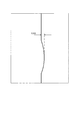
ディンプルを配置することは、フィンの使用目的、または所望の効果によって影響され得る。図4を参照すると、予想される迎え角に基づく、ディンプルの好ましい位置が示されている。迎え角は、水流がフィンと接触するときの水流の方向である。図4aにおいて、フィンが直線上を移動している場合、フォイルの断面の最も広い箇所の後部にディンプルを形成することで、層流剥離泡が生じない、きれいな移行部をもたらすことができる。このきれいな移行部は、フォイルによって引き起こされる圧力抗力を低減し、したがって性能を向上させる。移行部とは、流れが層流から乱流へと変化し始めるところである。圧力が高圧から低圧に変化するときに、流れはフォイルから離れる。 The placement of dimples can be affected by the intended use of the fins or the desired effect. Referring to FIG. 4, the preferred position of the dimple based on the expected angle of attack is shown. The angle of attack is the direction of water flow when the water flow contacts the fins. In FIG. 4a, when the fins are moving on a straight line, forming a dimple at the rear of the widest section of the foil can provide a clean transition without laminar separation bubbles. This clean transition reduces the pressure drag caused by the foil and thus improves performance. The transition is where the flow begins to change from laminar to turbulent. When the pressure changes from high pressure to low pressure, the flow leaves the foil.
流体がフィン(フォイル)上を流れるときに、フィン表面と流体が乱されない場所との間に境界層と呼ばれる流体層が存在する。フィンの輪郭に応じて、フィンの表面の大部分を横切る薄い境界層内を水が滑らかに流れることが多くある。境界層は前縁付近では層流であり、前縁から(表面粗さおよびレイノルズ数(速度)に応じた)一定距離の位置で乱流になる。しかし、正圧勾配の大きさに起因して、境界層がフィンの表面から離脱する点、すなわち剥離点に到達する。剥離点の後部の伴流の圧力が下がるために、剥離層の下では、停滞水形態の泡が生じて追加の抗力を作り出す。 As the fluid flows over the fins (foils), there is a fluid layer called a boundary layer between the fin surface and where the fluid is not disturbed. Depending on the fin profile, water often flows smoothly through a thin boundary layer across most of the fin surface. The boundary layer is laminar near the leading edge, and becomes turbulent at a certain distance (depending on surface roughness and Reynolds number (velocity)) from the leading edge. However, due to the magnitude of the positive pressure gradient, the boundary layer reaches the point where it departs from the surface of the fin, that is, the separation point. As the pressure of the wake behind the peel point drops, under the peel layer, stagnant water form bubbles are created creating additional drag.
これらの泡は、境界層を乱流にするディンプルを追加することにより減らすことができ、場合によってはなくすことができる。乱流境界層はより大きなエネルギーを含んでおり、したがって、乱流境界層は、より大きな負圧勾配が到達するまで剥離を遅らせ、剥離点をフォイル上で更に後部に効果的に移動させ、場合によっては剥離を完全になくす。乱流境界層の結果、層流境界層に対する表面摩擦が増加するが、これは、剥離に関連する抗力の増加に比べて非常に小さい。 These bubbles can be reduced and possibly eliminated by adding dimples that turbulent the boundary layer. The turbulent boundary layer contains more energy, so the turbulent boundary layer delays separation until a larger negative pressure gradient is reached, effectively moving the separation point further back on the foil In some cases, peeling is completely eliminated. As a result of the turbulent boundary layer, surface friction against the laminar boundary layer is increased, which is very small compared to the increase in drag associated with separation.
ボードの乗り手が急激なターンを試みるとき、迎え角はかなり大きいものと考えられる。この場合は、図4bおよび図4cに例示されている。サーフボードは、円弧状に、またはS字ターンで、通常は0度〜35度および0度〜360度ターンする。大きい迎え角とで、直線経路に対して35度を超えるであろう。 When the board rider attempts a sharp turn, the angle of attack is considered quite large. This case is illustrated in FIGS. 4b and 4c. Surfboards typically turn 0-35 degrees and 0-360 degrees in an arc or S-turn. With a large angle of attack, it will exceed 35 degrees for a straight path.
ディンプルが、図4bに示されているように、フィンの片側にのみ配置される実施形態もある。一般に、これはフィンの揚力発生側となる。しかし、他の配置では、ディンプルは、図4cに示されているように、フィンの両側に配置される。これは、特に非対称フィンの場合である。 In some embodiments, the dimples are located only on one side of the fin, as shown in FIG. 4b. In general, this is the lift generation side of the fin. However, in other arrangements, the dimples are placed on both sides of the fin, as shown in FIG. 4c. This is especially the case for asymmetric fins.
これは、フォイルの内側からの剥離を低減することにもなる。サーフボードは一般に2つ以上のフィンを有し、各側面は異なる角度で流れと接触する。フォイル性能を最大限にするために、フォイルの両側面における剥離を低減することが望ましい。剥離は、フィンの湾曲外側面とは反対側の平坦な内側面上の様々な領域内で起こる。 This also reduces peeling from the inside of the foil. Surfboards typically have two or more fins, each side contacting the flow at a different angle. In order to maximize foil performance, it is desirable to reduce delamination on both sides of the foil. Delamination occurs in various regions on the flat inner surface opposite the curved outer surface of the fin.
ディンプル付き表面は、乱流領域へ早く移行させる。これは、表面から水の剥離を制御するという利点を有する。 The dimpled surface moves quickly to the turbulent region. This has the advantage of controlling the separation of water from the surface.
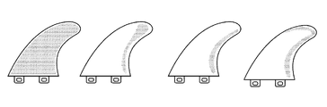
所望される性能に応じて、ディンプルは、フィンの表面上のより小さな、もしくは大きな範囲に配置されてもよく、またはフィンの複数の部分に配置されてもよい。図9を参照すると、様々な実施形態が、フィンのディンプル付き部分をそれぞれ網掛けの状態にして示されている。 Depending on the desired performance, the dimples may be placed in a smaller or larger area on the surface of the fin, or may be placed in multiple portions of the fin. Referring to FIG. 9, various embodiments are shown with the dimpled portions of the fins each shaded.
様々な変形形態はそれぞれ、異なる感触および異なる性能を提供する。サーフィンする際の状況もまた様々であり、様々なディンプルの配置が異なる状況に応じて好まれ得る。すなわち、ディンプルの適用範囲を大きくすることにより、グリッピア感触(grippier feel)が得られ、フィンがすべり出る感触が少なくなるので、この配置は、より急な波およびより大きな波においてより良好であろう。 Each of the various variations provides a different feel and different performance. There are also various situations when surfing, and the arrangement of various dimples may be preferred according to different circumstances. That is, increasing the dimple coverage will give a gripper feel and less feel the fin will slide out, so this arrangement will be better on steep and larger waves .
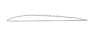
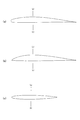
概して言えば、フィンは能動的湾曲面および平坦面を有する。一般的な例外が、シングルフィンおよびトライフィン配置のセンターフィンである。この場合、センターフィンは通常は対称形であり、両側が湾曲している。これらの一般的なフォイル形状が図11に見られる。図11bは、湾曲した上面および平坦な内面を示す。図11aは、湾曲上面およびわずかに湾曲した内面を示し、話を簡単にするために、内面を図11bのフォイルのように平坦と見なす。図11cは対称フォイル形状を示し、上面および内面が共に湾曲している。これは、一般にセンターフィンおよびシングルフィンとして使用されるフォイルである。 Generally speaking, the fin has an active curved surface and a flat surface. A common exception is center fins with single fin and trifin arrangements. In this case, the center fin is usually symmetrical and is curved on both sides. These common foil shapes can be seen in FIG. FIG. 11b shows a curved upper surface and a flat inner surface. FIG. 11a shows a curved upper surface and a slightly curved inner surface, for the sake of simplicity, consider the inner surface as flat as the foil of FIG. 11b. FIG. 11c shows a symmetrical foil shape, with the upper and inner surfaces both curved. This is a foil commonly used as a center fin and a single fin.
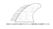
本発明では、主要なディンプルの配置はフィンの曲面上に置かれるものである。これらの配置は、上述され図9に例示されている。しかし、フィンの「平坦」面上にディンプルを形成することによっても、利益が得られる。図10は、フィンの平坦面上のディンプルの好ましい位置を示す。これらは、剥離が予想される領域である。 In the present invention, the main dimples are placed on the curved surfaces of the fins. These arrangements are described above and illustrated in FIG. However, it is also beneficial to form dimples on the “flat” surface of the fin. FIG. 10 shows the preferred position of the dimples on the flat surface of the fin. These are areas where delamination is expected.
好ましい配置では、ディンプルは円形である。波とサーファの操縦との組み合わせにより、流れが絶えず変化し、一方向からの定常流がないので、円形が好ましい。円形ディンプルは、円形ディンプルが様々な流れ角を対処するように、一様である。現代のサーフィンでは、サーファは360度ターンし、サーフボードに後ろ向きに乗ることがある。このような状況において、丸い円形ディンプルは、サーファが移動している方向がどの方向でも均一な結果を与えることができる。しかし、様々な異なる形状を使用することができる。ディンプルの好ましい形状が図8に示されている。ディンプル形状を使用目的に応じて選択してもよい。異なる性能が異なるクラフトに求められる場合もある。例えば、ウェイクボード(wake board)は、ボートの後部に曳航され、一般に直線上を進み、サーフボードほど広い迎え角を受けない。したがって、ウェイクボードは、円形でないディンプル、例えば六角形のディンプルから恩恵を受けることができるが、この場合でも、円形ディンプルが性能を向上させることが理解されよう。 In a preferred arrangement, the dimples are circular. A combination of wave and surfer maneuvering is preferred because the flow is constantly changing and there is no steady flow from one direction. The circular dimples are uniform so that the circular dimples deal with various flow angles. In modern surfing, surfers can turn 360 degrees and ride surfboards backwards. In such a situation, the round circular dimple can give a uniform result in whatever direction the surfer is moving. However, a variety of different shapes can be used. A preferred shape of the dimple is shown in FIG. The dimple shape may be selected according to the purpose of use. Different performance may be required for different crafts. For example, a wake board is towed to the rear of a boat and generally travels in a straight line and does not receive as much angle of attack as a surfboard. Thus, the wakeboard can benefit from non-circular dimples, such as hexagonal dimples, but it will be appreciated that circular dimples still improve performance.
ほとんどの実施形態において、ディンプルは共通のサイズおよび形状を有する。しかし、場合によっては、異なるサイズのディンプルが利用されてもよい。これらの異なるサイズのディンプルは、フィンの最も広い箇所のすぐ前方の、前縁のよりタイトな丸み部分のところでより小さくすることができ(深さ0.1mm×幅2.0mm)、ディンプルが、最大サイズ、すなわち深さ0.325mm×幅4.0mmに達するまで、フォイルの湾曲形状面を横切るにつれて、ディンプルが約1.0mmずつ増大し、ディンプルが後縁に近づくにつれて1.0mmずつ減少して深さ0.1mm×幅2.0mmのサイズになる。 In most embodiments, the dimples have a common size and shape. However, in some cases, dimples having different sizes may be used. These different sized dimples can be made smaller at the tighter rounded part of the front edge, just in front of the widest part of the fin (depth 0.1 mm x width 2.0 mm), The dimple increases by about 1.0 mm as it crosses the curved surface of the foil until it reaches the maximum size, ie 0.325 mm depth x 4.0 mm width, and decreases by 1.0 mm as the dimple approaches the trailing edge. The depth is 0.1 mm and the width is 2.0 mm.
現時点の試験から、好ましいディンプルは2.0mm〜4.5mmの直径および0.1mm〜0.5mmの深さを有することが分かっている。直径が小さすぎ、例えば2.0mm未満であると、増大に対抗するために圧力抗力を減少させることも揚力を増大させることもなく抗力を増大させ、同様に、直径が大きすぎ、例えば5mmを超えると、表面積は過度に増大し、やはり抗力が作られることが分かっている。 Current testing has shown that preferred dimples have a diameter of 2.0 mm to 4.5 mm and a depth of 0.1 mm to 0.5 mm. If the diameter is too small, for example less than 2.0 mm, it will increase the drag without decreasing the pressure drag or increase the lift to counter the increase, and similarly the diameter will be too large, for example 5 mm. Beyond that, it has been found that the surface area increases excessively and drag is still created.
好ましい実施形態では、ディンプルの直径は2.0mm〜4.5mmであり、最適直径は3.8mm〜4.3mmである。更に、ディンプルの深さの範囲は0.2mmから0.5mmであり、理想的な範囲は0.28mm〜0.325mmである。 In a preferred embodiment, the dimple has a diameter of 2.0 mm to 4.5 mm and an optimum diameter of 3.8 mm to 4.3 mm. Further, the depth range of the dimple is 0.2 mm to 0.5 mm, and the ideal range is 0.28 mm to 0.325 mm.
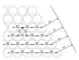
好ましい構成では、図16および図17に例示されているように、ディンプルは4.036mmの直径および0.325mmの深さを有する。好ましくは、ディンプルの中心は、互いに4.378mm離れて配置されて、ディンプル相互間に0.367mmの間隔を与える。 In a preferred configuration, as illustrated in FIGS. 16 and 17, the dimples have a diameter of 4.036 mm and a depth of 0.325 mm. Preferably, the centers of the dimples are spaced 4.378 mm apart from each other to provide a 0.367 mm spacing between the dimples.
別の構成が、本発明の他の好ましい実施形態の様々な直径、深さ、およびスペースを示す図18に例示されている。 Another configuration is illustrated in FIG. 18 showing various diameters, depths, and spaces of other preferred embodiments of the present invention.
理想的には、ディンプルは、ディンプル縁部相互間の距離が0.2mm〜5mmになるように配置される。各ディンプルの縁部相互間の理想的距離は0.3mm〜0.4mmである。 Ideally, the dimples are arranged such that the distance between the dimple edges is 0.2 mm to 5 mm. The ideal distance between the edges of each dimple is 0.3 mm to 0.4 mm.
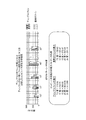
各ディンプルの中心間の距離を検討するに当たって、好ましい範囲は3.70mm〜4.5mmである。上記の構成では、フィンの片面のディンプルの数は350〜900個であることが好ましい。片面のディンプル数の範囲はフィンのサイズに依存する。例えば、小型フィン、中型フィン、および大型フィンは、下記の寸法およびディンプルを有していてもよい。 In examining the distance between the centers of each dimple, the preferred range is 3.70 mm to 4.5 mm. In the above configuration, the number of dimples on one side of the fin is preferably 350 to 900. The range of the number of dimples on one side depends on the size of the fin. For example, the small fin, the medium fin, and the large fin may have the following dimensions and dimples.
a)小型左右サイドフィン、対称フォイル:
ベース:101.0mm(3.98インチ)
デプス:105.0mm
面積:8964.0mm2
図19に示されているように、湾曲外面上に382個の直径3.76mmのディンプルを有している。
a) Small left and right side fins, symmetrical foil:
Base: 101.0 mm (3.98 inches)
Depth: 105.0mm
Area: 8964.0 mm 2
As shown in FIG. 19, there are 382 dimples with a diameter of 3.76 mm on the curved outer surface.
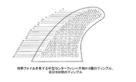
b)小型センターフィン、対称フォイル:
ベース:100.0mm(3.98インチ)
デプス:105.0mm
面積:8964.0mm2
図20は、一方の外面を示しており、反対側は、反転された同様の形状を有し、両湾曲外面上に764個の直径3.76mmのディンプルを有している。
b) Small center fin, symmetrical foil:
Base: 100.0 mm (3.98 inches)
Depth: 105.0mm
Area: 8964.0 mm 2
FIG. 20 shows one outer surface, the opposite side having a similar inverted shape, with 764 dimples with a diameter of 3.76 mm on both curved outer surfaces.
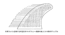
c)中型左右サイドフィン、対称フォイル:
ベース:110.0mm(4.37インチ)
デプス:115.0mm(4.55インチ)
面積:9608.0mm2
図21は、湾曲外面上に418個の直径4.15mmのディンプルを示す。
c) Medium left and right side fins, symmetrical foil:
Base: 110.0 mm (4.37 inches)
Depth: 115.0 mm (4.55 inches)
Area: 9608.0 mm 2
FIG. 21 shows 418 4.15 mm diameter dimples on the curved outer surface.
d)中型センターフィン、対称フォイル:
ベース:110.0mm(4.37インチ)
デプス:115.0mm(4.55インチ)
面積:9608.0mm2
図22は、一方の外面を示しており、反対側は反転された同様の形状を有し、両湾曲外面上に836個の直径4.15mmのディンプルを有している。
d) Medium center fin, symmetric foil:
Base: 110.0 mm (4.37 inches)
Depth: 115.0 mm (4.55 inches)
Area: 9608.0 mm 2
FIG. 22 shows one outer surface, with the opposite side having a similar inverted shape, with 836 diameter 4.15 mm dimples on both curved outer surfaces.
e)大型左右サイドフィン、対称フォイル:
ベース:116.0mm(4.55インチ)
デプス:115.0mm
面積:9608.0mm2
図23は、湾曲外面上に456個の直径4.036mmのディンプルを示す。
e) Large left and right side fins, symmetrical foil:
Base: 116.0 mm (4.55 inches)
Depth: 115.0mm
Area: 9608.0 mm 2
FIG. 23 shows 456 dimples having a diameter of 4.036 mm on the curved outer surface.
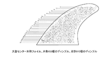
f)大型センターフィン、対称フォイル:
ベース:116.0mm(4.55インチ)
デプス:115.0mm
面積:9608.0mm2
f) Large center fin, symmetrical foil:
Base: 116.0 mm (4.55 inches)
Depth: 115.0mm
Area: 9608.0 mm 2
図24は、一方の外面を示しており、反対側は反転された同様の形状を有し、両湾曲外面上に910個の直径4.036mmのディンプルを有している。 FIG. 24 shows one outer surface, the opposite side having a similar inverted shape, with 910 dimples with a diameter of 4.036 mm on both curved outer surfaces.
また、図19〜図24は、各「列」に好ましい数のディンプルを示している。好ましい構成では、ディンプルの各列は、フィンが付着される、サーフボードまたはウォータークラフトの表面と実質的に平行である。これは、ディンプルの各列が、フィンのベースと実質的に平行であることと同じであり、フィンのベースは、サーフボードまたはウォータークラフトに連結される。好ましい構成では、ディンプルの列は実質的に平行、すなわち180度であるが、他の実施形態では、ディンプルは170度〜190度で配置されていてもよい。すなわち、ディンプルの列の好ましい角度はフィンのベースと平行であるが、最大で10°のばらつきが許容できる。 19 to 24 show a preferable number of dimples in each “row”. In a preferred configuration, each row of dimples is substantially parallel to the surface of the surfboard or watercraft to which the fins are attached. This is the same as each row of dimples being substantially parallel to the fin base, which is connected to the surfboard or watercraft. In a preferred configuration, the rows of dimples are substantially parallel, i.e., 180 degrees, but in other embodiments, the dimples may be arranged between 170 degrees and 190 degrees. That is, the preferred angle of the dimple row is parallel to the base of the fin, but a variation of up to 10 ° is acceptable.
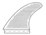
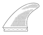
ディンプルを有するフィンの様々な実施形態が提供され得る。一実施形態では、図5に示されているように、実質的にフィンの全外表面にディンプルが形成されるが、ディンプルは縁部からセットバックして配置される。理想的には、フィンの前縁は、フォイルの曲線を維持し、コアンダ効果を妨げないようにするべく、ディンプルを形成するべきではない。同様に、好ましい構成では、フィンの後縁は、フォイルの薄くなった部分における振動を低減するために、ディンプルが形成されない。ディンプルは後縁から5mm以上離れていることが理想的である。 Various embodiments of fins having dimples may be provided. In one embodiment, as shown in FIG. 5, dimples are formed on substantially the entire outer surface of the fin, but the dimples are placed back from the edge. Ideally, the leading edge of the fin should not form dimples so as to maintain the foil curve and not interfere with the Coanda effect. Similarly, in the preferred arrangement, the trailing edge of the fin is not dimpled to reduce vibration in the thinned portion of the foil. Ideally, the dimple should be at least 5 mm away from the trailing edge.
図25および図26は、フィンの縁部からの好ましいセットバックを示す。図25から、ディンプルの列と平行な線におけるフィンの縁部からのセットバックは5.0mm〜60.0mmであることが分かる。あるいは、図26を参照すると、フィンの縁部に最も近接する各ディンプルの中心は、フィンの縁部から垂直に8.0mm〜60.0mmに配置される。 Figures 25 and 26 show a preferred setback from the edge of the fin. From FIG. 25, it can be seen that the setback from the edge of the fin in the line parallel to the row of dimples is 5.0 mm to 60.0 mm. Alternatively, referring to FIG. 26, the center of each dimple that is closest to the edge of the fin is positioned 8.0 mm to 60.0 mm vertically from the edge of the fin.
本発明の一実施形態の寸法に対する好ましいセットバックは、図27にも示されている。 A preferred setback for the dimensions of one embodiment of the present invention is also shown in FIG.
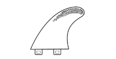
別の実施形態では、フィンは、フォイルの前縁からの設定距離に配置されたディンプル付き表面を有する。このオフセット距離は、フォイルの最も広い箇所がある場所を基準にして、ディンプルがこの最も広い箇所より後ろで始まるように決定することができる。フォイルの最も広い箇所の後ろに、流れが剥離しやすい場所がある。最も広い箇所の後ろに置かれるディンプルは、逆流を引き寄せる乱流層を作ることにより剥離を低減する。 In another embodiment, the fin has a dimpled surface disposed at a set distance from the leading edge of the foil. This offset distance can be determined such that the dimples begin behind this widest point, relative to the location where the foil has the widest point. Behind the widest part of the foil is a place where the flow tends to peel off. Dimples placed behind the widest point reduce separation by creating a turbulent layer that draws backflow.
別の実施形態では、ディンプルは、計算流動力学が、最も大きい流れの剥離(およびキャビテーション)が起こると判断した領域内において、フィンに配置される。しかし、境界層が正圧勾配の大きさのためにフィンの表面から離脱する点、すなわち剥離点に到達する。剥離層の下では、剥離点の後ろの伴流において圧力が下がるため、停滞空気形態の泡が生じて追加の抗力を作り出す。 In another embodiment, the dimples are placed on the fins in a region where the computational flow dynamics have determined that the greatest flow separation (and cavitation) occurs. However, the boundary layer reaches the point where it departs from the surface of the fin due to the magnitude of the positive pressure gradient, that is, the separation point. Under the release layer, the pressure drops in the wake behind the release point, resulting in stagnant air form bubbles creating additional drag.
これらの泡は、剥離点を、より遠くへ移動させるようにフィンの形状を定めることにより、または、境界層を乱流にするディンプルを追加することにより、減らすことができ、場合によってはなくすことができる。乱流境界層はより大きなエネルギーを含んでおり、したがって、乱流境界層は、より大きな負圧勾配が到達するまで剥離を遅らせ、剥離点をフォイル上で更に後部に効果的に移動させ、場合によっては剥離を完全になくす。この剥離点は様々な形状のフィンによって異なり、計算流動力学によって、ディンプルを配置する最良の領域を判断することができる。 These bubbles can be reduced and possibly eliminated by shaping the fins to move the separation point further, or by adding dimples that turbulent the boundary layer. Can do. The turbulent boundary layer contains more energy, so the turbulent boundary layer delays separation until a larger negative pressure gradient is reached, effectively moving the separation point further back on the foil In some cases, peeling is completely eliminated. This peeling point differs depending on the fins of various shapes, and the best region for arranging the dimples can be determined by computational fluid dynamics.
これまでのフィンの設計は滑らかな表面を規定している。従来の考えに反して、本発明は、サーフボードをより良く制御するためにディンプル付き表面を導入することにより、ウォータークラフトのフィン、例えば現代のサーフィンにおけるサーフボードのフィン(迎え角が高い場合の動的操縦性を有する)の性能を向上させる。滑らかで平坦な表面を有する従来のフィン設計は、フィンのフォイル表面上で流れが剥離することによって引き起こされるキャビテーションに起因して、大きく方向が変化する波にフィンをホールドし続けることができない。 Previous fin designs define a smooth surface. Contrary to conventional belief, the present invention introduces a dimpled surface for better control of the surfboard, thereby providing watercraft fins, such as surfboard fins in modern surfing To improve the performance). Conventional fin designs with smooth and flat surfaces cannot continue to hold the fins in highly diverging waves due to cavitation caused by flow separation on the foil surface of the fin.
ディンプル設計は、乱流を利用して流れの剥離を遅らせ、キャビテーションおよび抗力を低減する。乱流境界層は、流れが逆圧力勾配に打ち勝ち、乱流境界層がない場合よりも長く流れが表面に付着され続けるよう助ける。 The dimple design utilizes turbulence to delay flow separation and reduce cavitation and drag. The turbulent boundary layer helps the flow overcome the counter pressure gradient and continue to adhere to the surface longer than without the turbulent boundary layer.
「波を捉え」かつ水中にボードを推進させる過程にあるサーファは、各フィンのいずれかの側面の周囲のいわゆる「付着した層状流体流れ」が、この直線運動中のコアンダ効果に続いて起こることを規定する流体力学の物理的現象の効果を感じる。 Surfers in the process of “capturing waves” and propelling the board into the water have a so-called “adhered laminar fluid flow” around either side of each fin, following the Coanda effect during this linear motion. Feel the effects of physical phenomena of fluid dynamics that regulate
本発明のディンプルのサイズ、深さ、およびディンプル間距離は重要であり、フィンの総合的性能および製造に大きな影響を及ぼす。ディンプルが深さおよび幅に関して大きすぎる場合、ディンプルの表面積が過大になり、抗力が増大することになる。更に、揚力が低下し、したがって増大した抗力を相殺できなくなる。その上、ディンプルが大きくなり深くなると、フィンを作るために使用される材料の曲げ特性は変化し始め、その領域の材料が薄くなりすぎ、たわみやすくまたは砕けやすくなりすぎ、それによって性能を低下させ、フィンの製造を困難なものにする。逆に、小さすぎるまたは浅すぎるディンプルは性能向上をもたらすことがなく、むしろフィンの抗力を増大させる。ディンプル相互間の距離は、フィンの性能にも影響を及ぼす。ディンプルが互いに近すぎるか、更に接していると、ディンプルはフォイル曲面の形状を変形させる効果を有し、それによりフィンおよびコアンダ効果によって生成される揚力を低下させる。ディンプルが互いに接近しすぎていることも、フィンを作るために使用される材料の曲げ特性にも影響を及ぼし、その領域の材料が薄くなり、たわみやすくなりすぎ、それによって性能を低下させ、フィンの製造を困難なものにする。逆に、ディンプルが互いに遠く離れすぎていると、ディンプルによって生成される揚力の大きさを低減し、したがって抗力を相殺することができない。このように、本発明は、当業界内の従来の考えに反する改良された性能が得られるディンプルのパラメータを提供する。 The dimple size, depth, and distance between the dimples of the present invention are important and greatly affect the overall performance and manufacturing of the fins. If the dimples are too large with respect to depth and width, the surface area of the dimples will be excessive and drag will increase. Furthermore, the lift is reduced and therefore the increased drag cannot be offset. In addition, as the dimples grow larger and deeper, the bending properties of the material used to make the fins begin to change, and the material in that region becomes too thin, too flexible or friable, thereby reducing performance. Making fins difficult to manufacture. Conversely, dimples that are too small or too shallow do not provide improved performance, but rather increase the drag of the fins. The distance between the dimples also affects the performance of the fins. If the dimples are too close or in contact with each other, the dimples have the effect of deforming the shape of the foil curved surface, thereby reducing the lift generated by the fin and coanda effects. The fact that the dimples are too close to each other also affects the bending properties of the material used to make the fins, making the material in that region thinner and more flexible, thereby reducing performance and reducing the fins. Making it difficult to manufacture. Conversely, if the dimples are too far away from each other, the amount of lift generated by the dimples can be reduced and therefore the drag cannot be offset. Thus, the present invention provides dimple parameters that provide improved performance contrary to conventional thinking within the industry.
本発明のフィンは既知のプラスチック射出成形技術を用いて生産されると考えられる。射出成形は、熱可塑性プラスチック材料と熱硬化性プラスチック材料の両方から部品を作るための製造工程である。材料が、加熱されたバレル内に供給され、混合され、そして金型空洞内に入れられ、そこで材料が冷やされ、空洞の構造に硬化する。 The fins of the present invention are believed to be produced using known plastic injection molding techniques. Injection molding is a manufacturing process for making parts from both thermoplastic and thermoset plastic materials. The material is fed into a heated barrel, mixed, and placed in a mold cavity where the material is cooled and hardened into a cavity structure.
射出成形は好ましい選択肢となり得るが、CNCカット、真空成形、鋳造などの他の技術が用いられてもよい。材料の選択もまた、用いられる製造技法、および所望の効果に依存する。適当な材料としては、繊維ガラス、ポリエステル、ポリカーボネート、ガラス繊維付きポリカーボネート、ナイロン、ガラス繊維付きナイロン、アルミニウム、エポキシ、木材、ゴム、および他の熱可塑性材料が挙げられる。プラスチック射出の場合、繊維ガラスの曲げ特性を模倣する好ましい材料は、ガラス繊維を30〜50%含むナイロン、もしくは代替的に炭素繊維を30〜50%含むナイロン、またはKEVLAR(登録商標)である。繊維ガラスの曲げ特性が維持されることは重要ではないが、現在のサーファは、既存の繊維ガラスの感触に満足しており、したがって、同様の曲げ特性を提供することを好む。 Injection molding can be a preferred option, but other techniques such as CNC cutting, vacuum forming, casting, etc. may be used. The choice of material will also depend on the manufacturing technique used and the desired effect. Suitable materials include fiberglass, polyester, polycarbonate, polycarbonate with glass fiber, nylon, nylon with glass fiber, aluminum, epoxy, wood, rubber, and other thermoplastic materials. In the case of plastic injection, a preferred material that mimics the bending properties of fiberglass is nylon containing 30-50% glass fiber, or alternatively, nylon containing 30-50% carbon fiber, or KEVLAR®. While it is not important that the bending properties of the fiberglass be maintained, current surfers are satisfied with the feel of existing fiberglass and therefore prefer to provide similar bending properties.
一般に、ナイロンKEVLAR(登録商標)は、道具を用いた作業によってあまりすりへらないが、あまり使用されない材料であり、より高価であると考えられている。 In general, nylon KEVLAR® is considered a less expensive material that is less worn by work with tools, but less used.
Ensinger Industries IncのHydlar(商標)は適当な材料であることが分かっている。代替物がIG FarbenのNylon6(商標)である。 Ensinger Industries Inc.'s Hydlar ™ has been found to be a suitable material. An alternative is Nylon 6 ™ from IG Farben.
ナイロンがKEVLAR(登録商標)アラミド繊維で満たされると、ナイロンのみに比べて丈夫になり、耐摩耗性も高まる。そのような熱可塑性複合材は一般に、他の強化プラスチックより性能が優れており、特に、引張強度および曲げ強度が増す。 When nylon is filled with KEVLAR® aramid fibers, it is stronger and more wear resistant than nylon alone. Such thermoplastic composites generally outperform other reinforced plastics, and in particular have increased tensile strength and bending strength.
本発明の利点は、本発明に係るディンプル付きフィンの揚力(N)を従来のディンプルのないフィンと比較した図29に見られる。 The advantages of the present invention can be seen in FIG. 29 where the lift (N) of the dimpled fin according to the present invention is compared to a conventional fin without dimples.
図29のグラフは、様々な流れ角(迎え角)で、それぞれのフィンによってもたらされる結果的な揚力を示す。このグラフは、2つの重要なポイントを示している。第1に、本発明のディンプル設計では、揚力が7.5度〜15度の範囲でかなり増加している。この点で揚力が増加すると、サーファがボードをより強く押し、ターンにおける速度を上げることができるので、重要である。 The graph of FIG. 29 shows the resulting lift provided by each fin at various flow angles (attack angles). This graph shows two important points. First, in the dimple design of the present invention, the lift is significantly increased in the range of 7.5 degrees to 15 degrees. An increase in lift at this point is important because the surfer can push the board more strongly and increase the speed on the turn.
第2のポイントは、従来のフィン設計では、揚力が25度に達した後、大きな失速効果を低減できないことである。ディンプル付きフィンも、25度のポイントを過ぎて失速しているが、この失速は従来のフィンの場合ほど大きくないので、サーファは、ターンを終えるために必要なホールドを維持することができる。 The second point is that the conventional fin design cannot reduce the large stall effect after the lift reaches 25 degrees. The dimpled fin also stalls past the 25 degree point, but this stall is not as great as with the conventional fin, so the surfer can maintain the hold necessary to finish the turn.
この試験は、本明細書に記載のパラメータを有するディンプル付きフィンが、従来のフィンに比べて、揚力を増大させ、圧力抗力を低減し、フィンのフィン性能を向上させるという出願者らの主張を支援する。 This test is based on Applicants' claims that a dimpled fin having the parameters described herein increases lift, reduces pressure drag, and improves fin fin performance compared to conventional fins. Support.
本発明の利点は、流れの流線がフィンに近づき、フィンを越えて行くときのシミュレーション上の流線を示す図28aおよび図28bにも見られる。図28aは標準の、すなわち従来のフィンの上の流れを示し、図28bは、同様に設計され、ディンプルが追加されたフィン上の流れを示す。図28aは特にフィン先端渦を示す。フィン先端渦は、フィンが揚力を発生させるときにフィンの後部に残される回転流体の環状パターンである。フィンが流体学的揚力を発生させたとき、上面上の流体の圧力は底面に比べて低い。流体は、フィンの下および先端部周囲からフィンの上部へ環状に流れる。渦と呼ばれる突発的な環状流れパターンが観察され、低圧コアを特徴としている。 The advantages of the present invention can also be seen in FIGS. 28a and 28b, which show simulated streamlines as the flow streamlines approach the fins and go over the fins. FIG. 28a shows the flow over a standard or conventional fin, and FIG. 28b shows the flow over a fin similarly designed and with dimples added. FIG. 28a shows in particular the fin tip vortex. The fin tip vortex is an annular pattern of rotating fluid that is left behind the fin when the fin generates lift. When the fins generate hydrodynamic lift, the pressure of the fluid on the top surface is low compared to the bottom surface. The fluid flows annularly from below the fin and around the tip to the top of the fin. A sudden annular flow pattern called a vortex is observed and is characterized by a low pressure core.
これらの先端渦を検討するに当たって、図28aおよび図28bのシミュレーションの図は、やはり本発明の2つの態様を示している。第1に、標準フィンの先端部は、先端部の伴流の中にらせん形を描く乱流を有する。これは、先端渦として知られるものである。先端渦は、フィンの抗力、失速、および性能低下をもたらす。フィン上にディンプルを形成することで先端渦の大部分を取り除き、結果として、従来のフィンに比べて、抗力を低減し、失速を低減し、総合的性能を向上させる。 In considering these tip vortices, the simulation diagrams of FIGS. 28a and 28b again illustrate two aspects of the present invention. First, the tip of the standard fin has a turbulent flow that draws a spiral in the wake of the tip. This is known as the tip vortex. The tip vortex results in fin drag, stall, and performance degradation. Forming dimples on the fins removes most of the tip vortex and, as a result, reduces drag, reduces stall, and improves overall performance compared to conventional fins.
図に見られる第2の態様は、標準フィンによって作られる伴流がディンプル付きフィンによって作られる伴流よりも著しく大きいことである。これは、ディンプルが水中を通過する際に起こす、流れの剥離またはキャビテーションが標準フィンに比べて小さく、ディンプルが水中をより効率的に通過していることを示している。 The second aspect seen in the figure is that the wake created by the standard fin is significantly larger than the wake created by the dimpled fin. This indicates that the flow separation or cavitation that occurs when the dimples pass through the water is smaller than that of the standard fins, and the dimples pass through the water more efficiently.
本出願以前は、フィンは、フィンの全領域にわたって滑らかな表面であることが所望され、かつ一般的であった。これに反して、本発明は、フィン上のディンプル付き表面領域が、フィンによって生成される揚力を驚くほど増大させるとともに、圧力抗力および先端渦の効果を低減することを開示している。 Prior to this application, it was desirable and common for fins to be a smooth surface over the entire area of the fin. On the contrary, the present invention discloses that the dimpled surface area on the fin surprisingly increases the lift generated by the fin and reduces the effects of pressure drag and tip vortex.
従来の考えに反して、本発明のディンプル付きフィンは、水中でのホールドおよびグリップを維持しながら、より優れたドライブおよび操縦性を提供する。この水中でのホールドおよびグリップは、通常は、重要な操縦で滑らかなフィンを使用した際に犠牲となっていた。 Contrary to conventional thinking, the dimpled fin of the present invention provides better drive and maneuverability while maintaining hold and grip in water. This hold and grip in the water was usually sacrificed when using smooth fins for critical maneuvers.
本出願以前は、ディンプルの追加は、フィンの表面積、抗力を増大させ、それによって性能を低下させる欠陥をもたらすと考えられていた。 Prior to this application, the addition of dimples was thought to result in defects that increase the surface area, drag of the fins, thereby reducing performance.
本明細書に記述されているようにフィンの表面上にディンプルを追加することで、作られる乱流を利用して、水流とフィンの表面との接続を、高い迎え角を受けたときの大きな方向転換の際により長く維持する。これは、操縦中のフィンの速度およびホールド能力を維持し、それによってサーフボードの性能を向上させる。 By adding dimples on the surface of the fin as described herein, the turbulence created is used to make the connection between the water flow and the surface of the fin large when subjected to a high angle of attack. Keep longer when turning. This maintains the speed and hold capability of the fins during maneuvering, thereby improving the performance of the surfboard.
本発明は、サーフボード用のフィンに関して説明されているが、フィンは他のウォータークラフトにも使用され得ることが理解されよう。例えば、ボディーボード、カイトボード、スタンドアップパドルボード、ウェイクボードなどである。 Although the present invention has been described with reference to fins for surfboards, it will be understood that the fins can be used in other watercrafts. For example, body boards, kite boards, stand-up paddle boards, wake boards, and the like.
本明細書を通じて、「一(one、an)」実施形態への言及は、実施形態に関連して記述される特定の特徴、構造、または特性が本発明の少なくとも1つの実施形態に含まれることを意味する。したがって、本明細書を通じて様々な箇所で用いられている「一実施形態では(in one embodiment、in an embodiment)」という語句は、必ずしもすべてが同じ実施形態を参照しているわけではない。 Throughout this specification, reference to “one, an” embodiment includes that a particular feature, structure, or characteristic described in connection with the embodiment is included in at least one embodiment of the invention. Means. Thus, the phrases “in one embodiment” in various places throughout this specification are not necessarily all referring to the same embodiment.
更に、特定の特徴、構造、または特性は、適切な方法で組み合わされて1つまたは複数の組み合わせを構成することができる。当業者であれば、本発明を上述した実施形態と異なる態様で実施することができ、変形実施形態は本発明の精神および範囲から逸脱することなく削減され得ることが理解されよう。 Furthermore, the particular features, structures, or characteristics may be combined in any suitable manner to form one or more combinations. Those skilled in the art will appreciate that the present invention may be implemented in a manner different from that described above, and that alternative embodiments may be reduced without departing from the spirit and scope of the present invention.
本明細書における検討もしくは文献、装置、行為、または知識は、本発明の背景を説明するために示されている。本明細書に係る特許出願の日以前に、いずれかの国において、従来技術の基礎または関連技術分野における共通一般知識の一部をなす材料については、省略されていると見なされるべきでない。 Discussion or literature, apparatus, acts, or knowledge in this specification is presented to illustrate the context of the invention. Prior to the date of the filing of a patent application herein, materials that form part of the common general knowledge in the basics of the prior art or related technical fields in any country should not be considered omitted.
Claims (19)
Applications Claiming Priority (5)
| Application Number | Priority Date | Filing Date | Title |
|---|---|---|---|
| AU2012902195 | 2012-05-28 | ||
| AU2012902195A AU2012902195A0 (en) | 2012-05-28 | Watercraft Fin | |
| AU2012905498A AU2012905498A0 (en) | 2012-12-14 | Watercraft fin | |
| AU2012905498 | 2012-12-14 | ||
| PCT/AU2013/000548 WO2013177612A1 (en) | 2012-05-28 | 2013-05-28 | Watercraft fin |
Publications (2)
| Publication Number | Publication Date |
|---|---|
| JP2015517954A true JP2015517954A (en) | 2015-06-25 |
| JP2015517954A5 JP2015517954A5 (en) | 2016-06-30 |
Family
ID=49672171
Family Applications (1)
| Application Number | Title | Priority Date | Filing Date |
|---|---|---|---|
| JP2015514285A Pending JP2015517954A (en) | 2012-05-28 | 2013-05-28 | Watercraft fins |
Country Status (9)
| Country | Link |
|---|---|
| US (1) | US20150104988A1 (en) |
| EP (1) | EP2855256A4 (en) |
| JP (1) | JP2015517954A (en) |
| CN (1) | CN204822021U (en) |
| BR (1) | BR112014029748A2 (en) |
| CA (1) | CA2874038A1 (en) |
| MX (1) | MX2014014510A (en) |
| NZ (1) | NZ703435A (en) |
| WO (1) | WO2013177612A1 (en) |
Families Citing this family (10)
| Publication number | Priority date | Publication date | Assignee | Title |
|---|---|---|---|---|
| JP6382603B2 (en) * | 2013-08-20 | 2018-08-29 | 株式会社東芝 | Water wheel |
| US9463588B2 (en) | 2014-02-07 | 2016-10-11 | Todas Santos Surf, Inc. | Surf fin including injection molded pre-impregnated composite fiber matrix inserts |
| WO2016083977A1 (en) | 2014-11-24 | 2016-06-02 | Elenco De Qualidade Equipamentos De Controlo Unipessoal, Lda | Hull for vessel or board having hydrodynamic elements formed as recesses |
| DE102015103021A1 (en) * | 2015-03-03 | 2016-09-08 | Ellergon Antriebstechnik Gesellschaft M.B.H. | Hydrofoilfinne |
| CN104787259B (en) * | 2015-04-27 | 2016-11-16 | 东莞市诺峰实业有限公司 | A kind of surfboard fin and processing technology thereof |
| US10106230B2 (en) * | 2015-06-02 | 2018-10-23 | Randal Richenberg | Biomimic design stabilizing fin or keel for surface planing or submerged watercraft |
| WO2017027921A1 (en) * | 2015-08-18 | 2017-02-23 | Jbooks Holdings Pty Ltd | A fin for a surfboard |
| US9637205B1 (en) | 2015-12-28 | 2017-05-02 | Jacob Saunooke | Curved surfboard fin |
| CN107902073A (en) * | 2017-12-20 | 2018-04-13 | 北航(四川)西部国际创新港科技有限公司 | Unmanned plane |
| IT201800003433A1 (en) * | 2018-03-12 | 2019-09-12 | Rovercraft Di F Russo | INTUBATED-TYPE MARINE THRUSTER WITH INCREASED PERFORMANCE |
Citations (3)
| Publication number | Priority date | Publication date | Assignee | Title |
|---|---|---|---|---|
| US5238434A (en) * | 1991-03-15 | 1993-08-24 | Kransco | Textured bottom skin for bodyboards and method |
| WO2009070852A1 (en) * | 2007-12-07 | 2009-06-11 | John Gene Foster | A watercraft stability control device |
| US20120103430A1 (en) * | 2010-10-27 | 2012-05-03 | Zuei-Ling Lin | Method of reducing the object-traveling resistance |
Family Cites Families (15)
| Publication number | Priority date | Publication date | Assignee | Title |
|---|---|---|---|---|
| US2261558A (en) * | 1939-02-28 | 1941-11-04 | Orloff Benjamin | Fluid supported vehicle and method of producing the same |
| US5167552A (en) * | 1990-02-01 | 1992-12-01 | Wellington Leisure Products, Inc. | Textured water sports board |
| US5114099A (en) * | 1990-06-04 | 1992-05-19 | W. L. Chow | Surface for low drag in turbulent flow |
| US5378524A (en) * | 1991-05-28 | 1995-01-03 | Blood; Charles L. | Friction reducing surface and devices employing such surfaces |
| US6336771B1 (en) * | 1996-10-08 | 2002-01-08 | Kenneth D. Hill | Rotatable wave-forming apparatus |
| US6019547A (en) * | 1996-10-08 | 2000-02-01 | Hill; Kenneth D. | Wave-forming apparatus |
| GB2346843B (en) * | 1997-10-27 | 2002-01-09 | Pat Tech Pty Ltd | Fin assembly |
| US6415730B1 (en) * | 2000-11-29 | 2002-07-09 | Westerngeco L.L.C. | Dimpled marine seismic fairing |
| US7029342B2 (en) * | 2003-05-07 | 2006-04-18 | Bruce Mallea | Reverse gate flow director |
| US7604461B2 (en) * | 2005-11-17 | 2009-10-20 | General Electric Company | Rotor blade for a wind turbine having aerodynamic feature elements |
| AU2007272289A1 (en) * | 2006-07-11 | 2008-01-17 | 3D Surf Accessories Pty Ltd | A fin assembly |
| GB0625612D0 (en) * | 2006-12-21 | 2007-01-31 | Queen Mary University Of Londo | Establishment of laminar boundary layer flow on aerofoil body |
| US8276851B2 (en) * | 2007-05-10 | 2012-10-02 | California Institute Of Technology | Control of aerodynamic forces by variable wetted surface morphology |
| US8863681B2 (en) * | 2008-03-28 | 2014-10-21 | Jonathan Sebastian Howes | Ventilated hydrofoils for watercraft |
| US8047801B2 (en) * | 2010-06-23 | 2011-11-01 | General Electric Company | Wind turbine blades with aerodynamic vortex elements |
-
2013
- 2013-05-28 MX MX2014014510A patent/MX2014014510A/en unknown
- 2013-05-28 EP EP13798201.3A patent/EP2855256A4/en not_active Withdrawn
- 2013-05-28 NZ NZ703435A patent/NZ703435A/en not_active IP Right Cessation
- 2013-05-28 WO PCT/AU2013/000548 patent/WO2013177612A1/en active Application Filing
- 2013-05-28 BR BR112014029748A patent/BR112014029748A2/en not_active IP Right Cessation
- 2013-05-28 JP JP2015514285A patent/JP2015517954A/en active Pending
- 2013-05-28 CN CN201390000593.0U patent/CN204822021U/en not_active Expired - Lifetime
- 2013-05-28 CA CA2874038A patent/CA2874038A1/en not_active Abandoned
- 2013-05-28 US US14/403,984 patent/US20150104988A1/en not_active Abandoned
Patent Citations (3)
| Publication number | Priority date | Publication date | Assignee | Title |
|---|---|---|---|---|
| US5238434A (en) * | 1991-03-15 | 1993-08-24 | Kransco | Textured bottom skin for bodyboards and method |
| WO2009070852A1 (en) * | 2007-12-07 | 2009-06-11 | John Gene Foster | A watercraft stability control device |
| US20120103430A1 (en) * | 2010-10-27 | 2012-05-03 | Zuei-Ling Lin | Method of reducing the object-traveling resistance |
Also Published As
| Publication number | Publication date |
|---|---|
| WO2013177612A1 (en) | 2013-12-05 |
| MX2014014510A (en) | 2015-07-06 |
| CA2874038A1 (en) | 2013-12-05 |
| EP2855256A1 (en) | 2015-04-08 |
| BR112014029748A2 (en) | 2017-06-27 |
| CN204822021U (en) | 2015-12-02 |
| EP2855256A4 (en) | 2016-03-23 |
| NZ703435A (en) | 2016-06-24 |
| US20150104988A1 (en) | 2015-04-16 |
Similar Documents
| Publication | Publication Date | Title |
|---|---|---|
| JP2015517954A (en) | Watercraft fins | |
| US8328593B2 (en) | Low-drag fin and foil system for surfboards | |
| US11679846B2 (en) | Fins with improved fluid dynamic properties | |
| WO2007050473A2 (en) | High-lift, low drag fin for surfboard and other watercraft | |
| US20180265174A1 (en) | Fins with improved fluid dynamic properties | |
| US20170001695A1 (en) | Fin Patent | |
| JP5889918B2 (en) | Foil structure for providing buoyancy and lift | |
| US6217402B1 (en) | Stabilizing element for use on mobile devices | |
| CN107117277A (en) | PODDED PROPULSOR with bionical conduit | |
| EP2447153A1 (en) | Method of enhancing the output efficiency of a propeller and reducing the noise thereof | |
| JP5064853B2 (en) | Helical wing propulsion, submerged floating catamaran | |
| KR20090106118A (en) | Apparatus for control of separation flow around ships | |
| JP6638941B2 (en) | Ship rudder with stern fins | |
| US6767266B2 (en) | Stabilizing element for use on mobile devices | |
| US6718897B1 (en) | Rideable wave propelled watersport board | |
| EP0459076B1 (en) | Stable racing catermaran with hydrofoil qualities | |
| US20120107130A1 (en) | Method of enhancing the output efficiency of a propeller and reducing the noise thereof | |
| US9205898B2 (en) | Fin structure for watercraft | |
| AU2005316366B2 (en) | Low-Drag Fin and Foil System for Surfboards | |
| US20050076819A1 (en) | Apparatus and method for reducing hydrofoil cavitation | |
| CN203975209U (en) | Composite energy-saving device on a kind of rudder | |
| WO2018126294A1 (en) | Channelled surfboard | |
| KR20140145242A (en) | A rudder for a ship | |
| CN216003033U (en) | Ship propeller blade with vortex reducing plate | |
| JP2013129408A (en) | Ship and manufacturing method thereof |
Legal Events
| Date | Code | Title | Description |
|---|---|---|---|
| A521 | Request for written amendment filed |
Free format text: JAPANESE INTERMEDIATE CODE: A523 Effective date: 20160513 |
|
| A621 | Written request for application examination |
Free format text: JAPANESE INTERMEDIATE CODE: A621 Effective date: 20160513 |
|
| A131 | Notification of reasons for refusal |
Free format text: JAPANESE INTERMEDIATE CODE: A131 Effective date: 20170221 |
|
| A977 | Report on retrieval |
Free format text: JAPANESE INTERMEDIATE CODE: A971007 Effective date: 20170223 |
|
| A601 | Written request for extension of time |
Free format text: JAPANESE INTERMEDIATE CODE: A601 Effective date: 20170519 |
|
| A601 | Written request for extension of time |
Free format text: JAPANESE INTERMEDIATE CODE: A601 Effective date: 20170721 |
|
| A02 | Decision of refusal |
Free format text: JAPANESE INTERMEDIATE CODE: A02 Effective date: 20171107 |