JP2015516516A - Silicon nanocomposite nanofiber - Google Patents
Silicon nanocomposite nanofiber Download PDFInfo
- Publication number
- JP2015516516A JP2015516516A JP2014560014A JP2014560014A JP2015516516A JP 2015516516 A JP2015516516 A JP 2015516516A JP 2014560014 A JP2014560014 A JP 2014560014A JP 2014560014 A JP2014560014 A JP 2014560014A JP 2015516516 A JP2015516516 A JP 2015516516A
- Authority
- JP
- Japan
- Prior art keywords
- silicon
- nanofibers
- nanocomposite
- nanofiber
- precursor
- Prior art date
- Legal status (The legal status is an assumption and is not a legal conclusion. Google has not performed a legal analysis and makes no representation as to the accuracy of the status listed.)
- Pending
Links
Images


Classifications
-
- H—ELECTRICITY
- H01—ELECTRIC ELEMENTS
- H01M—PROCESSES OR MEANS, e.g. BATTERIES, FOR THE DIRECT CONVERSION OF CHEMICAL ENERGY INTO ELECTRICAL ENERGY
- H01M50/00—Constructional details or processes of manufacture of the non-active parts of electrochemical cells other than fuel cells, e.g. hybrid cells
- H01M50/40—Separators; Membranes; Diaphragms; Spacing elements inside cells
- H01M50/409—Separators, membranes or diaphragms characterised by the material
- H01M50/446—Composite material consisting of a mixture of organic and inorganic materials
-
- D—TEXTILES; PAPER
- D01—NATURAL OR MAN-MADE THREADS OR FIBRES; SPINNING
- D01D—MECHANICAL METHODS OR APPARATUS IN THE MANUFACTURE OF ARTIFICIAL FILAMENTS, THREADS, FIBRES, BRISTLES OR RIBBONS
- D01D5/00—Formation of filaments, threads, or the like
- D01D5/0007—Electro-spinning
- D01D5/0015—Electro-spinning characterised by the initial state of the material
- D01D5/003—Electro-spinning characterised by the initial state of the material the material being a polymer solution or dispersion
-
- D—TEXTILES; PAPER
- D01—NATURAL OR MAN-MADE THREADS OR FIBRES; SPINNING
- D01D—MECHANICAL METHODS OR APPARATUS IN THE MANUFACTURE OF ARTIFICIAL FILAMENTS, THREADS, FIBRES, BRISTLES OR RIBBONS
- D01D5/00—Formation of filaments, threads, or the like
- D01D5/12—Stretch-spinning methods
- D01D5/14—Stretch-spinning methods with flowing liquid or gaseous stretching media, e.g. solution-blowing
-
- D—TEXTILES; PAPER
- D01—NATURAL OR MAN-MADE THREADS OR FIBRES; SPINNING
- D01F—CHEMICAL FEATURES IN THE MANUFACTURE OF ARTIFICIAL FILAMENTS, THREADS, FIBRES, BRISTLES OR RIBBONS; APPARATUS SPECIALLY ADAPTED FOR THE MANUFACTURE OF CARBON FILAMENTS
- D01F1/00—General methods for the manufacture of artificial filaments or the like
- D01F1/02—Addition of substances to the spinning solution or to the melt
- D01F1/09—Addition of substances to the spinning solution or to the melt for making electroconductive or anti-static filaments
-
- D—TEXTILES; PAPER
- D01—NATURAL OR MAN-MADE THREADS OR FIBRES; SPINNING
- D01F—CHEMICAL FEATURES IN THE MANUFACTURE OF ARTIFICIAL FILAMENTS, THREADS, FIBRES, BRISTLES OR RIBBONS; APPARATUS SPECIALLY ADAPTED FOR THE MANUFACTURE OF CARBON FILAMENTS
- D01F1/00—General methods for the manufacture of artificial filaments or the like
- D01F1/02—Addition of substances to the spinning solution or to the melt
- D01F1/10—Other agents for modifying properties
-
- D—TEXTILES; PAPER
- D01—NATURAL OR MAN-MADE THREADS OR FIBRES; SPINNING
- D01F—CHEMICAL FEATURES IN THE MANUFACTURE OF ARTIFICIAL FILAMENTS, THREADS, FIBRES, BRISTLES OR RIBBONS; APPARATUS SPECIALLY ADAPTED FOR THE MANUFACTURE OF CARBON FILAMENTS
- D01F9/00—Artificial filaments or the like of other substances; Manufacture thereof; Apparatus specially adapted for the manufacture of carbon filaments
- D01F9/08—Artificial filaments or the like of other substances; Manufacture thereof; Apparatus specially adapted for the manufacture of carbon filaments of inorganic material
- D01F9/12—Carbon filaments; Apparatus specially adapted for the manufacture thereof
- D01F9/14—Carbon filaments; Apparatus specially adapted for the manufacture thereof by decomposition of organic filaments
- D01F9/20—Carbon filaments; Apparatus specially adapted for the manufacture thereof by decomposition of organic filaments from polyaddition, polycondensation or polymerisation products
-
- H—ELECTRICITY
- H01—ELECTRIC ELEMENTS
- H01M—PROCESSES OR MEANS, e.g. BATTERIES, FOR THE DIRECT CONVERSION OF CHEMICAL ENERGY INTO ELECTRICAL ENERGY
- H01M10/00—Secondary cells; Manufacture thereof
- H01M10/05—Accumulators with non-aqueous electrolyte
- H01M10/052—Li-accumulators
- H01M10/0525—Rocking-chair batteries, i.e. batteries with lithium insertion or intercalation in both electrodes; Lithium-ion batteries
-
- H—ELECTRICITY
- H01—ELECTRIC ELEMENTS
- H01M—PROCESSES OR MEANS, e.g. BATTERIES, FOR THE DIRECT CONVERSION OF CHEMICAL ENERGY INTO ELECTRICAL ENERGY
- H01M4/00—Electrodes
- H01M4/02—Electrodes composed of, or comprising, active material
- H01M4/13—Electrodes for accumulators with non-aqueous electrolyte, e.g. for lithium-accumulators; Processes of manufacture thereof
- H01M4/133—Electrodes based on carbonaceous material, e.g. graphite-intercalation compounds or CFx
-
- H—ELECTRICITY
- H01—ELECTRIC ELEMENTS
- H01M—PROCESSES OR MEANS, e.g. BATTERIES, FOR THE DIRECT CONVERSION OF CHEMICAL ENERGY INTO ELECTRICAL ENERGY
- H01M4/00—Electrodes
- H01M4/02—Electrodes composed of, or comprising, active material
- H01M4/13—Electrodes for accumulators with non-aqueous electrolyte, e.g. for lithium-accumulators; Processes of manufacture thereof
- H01M4/139—Processes of manufacture
- H01M4/1393—Processes of manufacture of electrodes based on carbonaceous material, e.g. graphite-intercalation compounds or CFx
-
- H—ELECTRICITY
- H01—ELECTRIC ELEMENTS
- H01M—PROCESSES OR MEANS, e.g. BATTERIES, FOR THE DIRECT CONVERSION OF CHEMICAL ENERGY INTO ELECTRICAL ENERGY
- H01M4/00—Electrodes
- H01M4/02—Electrodes composed of, or comprising, active material
- H01M4/13—Electrodes for accumulators with non-aqueous electrolyte, e.g. for lithium-accumulators; Processes of manufacture thereof
- H01M4/139—Processes of manufacture
- H01M4/1395—Processes of manufacture of electrodes based on metals, Si or alloys
-
- H—ELECTRICITY
- H01—ELECTRIC ELEMENTS
- H01M—PROCESSES OR MEANS, e.g. BATTERIES, FOR THE DIRECT CONVERSION OF CHEMICAL ENERGY INTO ELECTRICAL ENERGY
- H01M4/00—Electrodes
- H01M4/02—Electrodes composed of, or comprising, active material
- H01M4/36—Selection of substances as active materials, active masses, active liquids
- H01M4/38—Selection of substances as active materials, active masses, active liquids of elements or alloys
- H01M4/386—Silicon or alloys based on silicon
-
- H—ELECTRICITY
- H01—ELECTRIC ELEMENTS
- H01M—PROCESSES OR MEANS, e.g. BATTERIES, FOR THE DIRECT CONVERSION OF CHEMICAL ENERGY INTO ELECTRICAL ENERGY
- H01M50/00—Constructional details or processes of manufacture of the non-active parts of electrochemical cells other than fuel cells, e.g. hybrid cells
- H01M50/40—Separators; Membranes; Diaphragms; Spacing elements inside cells
- H01M50/409—Separators, membranes or diaphragms characterised by the material
- H01M50/44—Fibrous material
-
- D—TEXTILES; PAPER
- D01—NATURAL OR MAN-MADE THREADS OR FIBRES; SPINNING
- D01D—MECHANICAL METHODS OR APPARATUS IN THE MANUFACTURE OF ARTIFICIAL FILAMENTS, THREADS, FIBRES, BRISTLES OR RIBBONS
- D01D5/00—Formation of filaments, threads, or the like
- D01D5/0007—Electro-spinning
- D01D5/0061—Electro-spinning characterised by the electro-spinning apparatus
- D01D5/0069—Electro-spinning characterised by the electro-spinning apparatus characterised by the spinning section, e.g. capillary tube, protrusion or pin
-
- H—ELECTRICITY
- H01—ELECTRIC ELEMENTS
- H01M—PROCESSES OR MEANS, e.g. BATTERIES, FOR THE DIRECT CONVERSION OF CHEMICAL ENERGY INTO ELECTRICAL ENERGY
- H01M4/00—Electrodes
- H01M4/02—Electrodes composed of, or comprising, active material
- H01M2004/021—Physical characteristics, e.g. porosity, surface area
-
- H—ELECTRICITY
- H01—ELECTRIC ELEMENTS
- H01M—PROCESSES OR MEANS, e.g. BATTERIES, FOR THE DIRECT CONVERSION OF CHEMICAL ENERGY INTO ELECTRICAL ENERGY
- H01M4/00—Electrodes
- H01M4/02—Electrodes composed of, or comprising, active material
- H01M4/04—Processes of manufacture in general
- H01M4/0438—Processes of manufacture in general by electrochemical processing
- H01M4/0469—Electroforming a self-supporting electrode; Electroforming of powdered electrode material
-
- H—ELECTRICITY
- H01—ELECTRIC ELEMENTS
- H01M—PROCESSES OR MEANS, e.g. BATTERIES, FOR THE DIRECT CONVERSION OF CHEMICAL ENERGY INTO ELECTRICAL ENERGY
- H01M4/00—Electrodes
- H01M4/02—Electrodes composed of, or comprising, active material
- H01M4/04—Processes of manufacture in general
- H01M4/0471—Processes of manufacture in general involving thermal treatment, e.g. firing, sintering, backing particulate active material, thermal decomposition, pyrolysis
-
- H—ELECTRICITY
- H01—ELECTRIC ELEMENTS
- H01M—PROCESSES OR MEANS, e.g. BATTERIES, FOR THE DIRECT CONVERSION OF CHEMICAL ENERGY INTO ELECTRICAL ENERGY
- H01M4/00—Electrodes
- H01M4/02—Electrodes composed of, or comprising, active material
- H01M4/13—Electrodes for accumulators with non-aqueous electrolyte, e.g. for lithium-accumulators; Processes of manufacture thereof
- H01M4/131—Electrodes based on mixed oxides or hydroxides, or on mixtures of oxides or hydroxides, e.g. LiCoOx
-
- H—ELECTRICITY
- H01—ELECTRIC ELEMENTS
- H01M—PROCESSES OR MEANS, e.g. BATTERIES, FOR THE DIRECT CONVERSION OF CHEMICAL ENERGY INTO ELECTRICAL ENERGY
- H01M4/00—Electrodes
- H01M4/02—Electrodes composed of, or comprising, active material
- H01M4/13—Electrodes for accumulators with non-aqueous electrolyte, e.g. for lithium-accumulators; Processes of manufacture thereof
- H01M4/134—Electrodes based on metals, Si or alloys
-
- H—ELECTRICITY
- H01—ELECTRIC ELEMENTS
- H01M—PROCESSES OR MEANS, e.g. BATTERIES, FOR THE DIRECT CONVERSION OF CHEMICAL ENERGY INTO ELECTRICAL ENERGY
- H01M4/00—Electrodes
- H01M4/02—Electrodes composed of, or comprising, active material
- H01M4/13—Electrodes for accumulators with non-aqueous electrolyte, e.g. for lithium-accumulators; Processes of manufacture thereof
- H01M4/136—Electrodes based on inorganic compounds other than oxides or hydroxides, e.g. sulfides, selenides, tellurides, halogenides or LiCoFy
-
- Y—GENERAL TAGGING OF NEW TECHNOLOGICAL DEVELOPMENTS; GENERAL TAGGING OF CROSS-SECTIONAL TECHNOLOGIES SPANNING OVER SEVERAL SECTIONS OF THE IPC; TECHNICAL SUBJECTS COVERED BY FORMER USPC CROSS-REFERENCE ART COLLECTIONS [XRACs] AND DIGESTS
- Y02—TECHNOLOGIES OR APPLICATIONS FOR MITIGATION OR ADAPTATION AGAINST CLIMATE CHANGE
- Y02E—REDUCTION OF GREENHOUSE GAS [GHG] EMISSIONS, RELATED TO ENERGY GENERATION, TRANSMISSION OR DISTRIBUTION
- Y02E60/00—Enabling technologies; Technologies with a potential or indirect contribution to GHG emissions mitigation
- Y02E60/10—Energy storage using batteries
-
- Y—GENERAL TAGGING OF NEW TECHNOLOGICAL DEVELOPMENTS; GENERAL TAGGING OF CROSS-SECTIONAL TECHNOLOGIES SPANNING OVER SEVERAL SECTIONS OF THE IPC; TECHNICAL SUBJECTS COVERED BY FORMER USPC CROSS-REFERENCE ART COLLECTIONS [XRACs] AND DIGESTS
- Y02—TECHNOLOGIES OR APPLICATIONS FOR MITIGATION OR ADAPTATION AGAINST CLIMATE CHANGE
- Y02T—CLIMATE CHANGE MITIGATION TECHNOLOGIES RELATED TO TRANSPORTATION
- Y02T10/00—Road transport of goods or passengers
- Y02T10/60—Other road transportation technologies with climate change mitigation effect
- Y02T10/70—Energy storage systems for electromobility, e.g. batteries
Abstract
本発明は、ケイ素ナノ複合ナノファイバーおよびその製造方法に関する。特定の態様において、本発明は、連続ケイ素材料を含有するナノ複合ナノファイバーと、非凝集ケイ素ドメインを含有するナノ複合ナノファイバーを提供する。The present invention relates to a silicon nanocomposite nanofiber and a method for producing the same. In certain embodiments, the present invention provides nanocomposite nanofibers containing continuous silicon material and nanocomposite nanofibers containing non-aggregated silicon domains.
Description
相互参照
本出願は、米国仮出願番号61/605937(2012年3月2日出願)、61/701854(2012年9月17日出願)、61/717222(2012年10月23日出願)の利益を主張し、これらの全てを参照することによりその全てが本発明に組み込まれる。
Cross-reference This application is a benefit of US Provisional Application Nos. 61/605937 (filed March 2, 2012), 61/701854 (filed September 17, 2012), 61/717222 (filed October 23, 2012). All of which are incorporated herein by reference.
本発明において、効率的なケイ素ナノ材料プラットフォームが提供される。 In the present invention, an efficient silicon nanomaterial platform is provided.
電池は、1つまたは複数の電気化学セルを含み、このようなセルは、一般的には、陽極、負極および電解質を含む。リチウムイオン電池は、極めて一般的に家電や電気自動車に使用される高エネルギー密度電池である。リチウムイオン電池において、リチウムイオンは、放電する間に、一般的に負極から陽極に移動し、充電時にはその逆の動きをする。製造されたままの状態および放電状態において、リチウムイオン電池は、多くの場合、カソード(陽極)にて(例えば、リチウム金属酸化物などの)リチウム化合物と、陽極(負極)にて他の材料、一般的に炭素を含む。 A battery includes one or more electrochemical cells, and such cells generally include an anode, a negative electrode, and an electrolyte. Lithium ion batteries are high energy density batteries that are very commonly used in home appliances and electric vehicles. In a lithium ion battery, lithium ions generally move from the negative electrode to the anode during discharge, and move in reverse during charging. In the as-manufactured and discharged state, lithium-ion batteries often have lithium compounds (eg, lithium metal oxides) at the cathode (anode) and other materials at the anode (negative electrode), Generally contains carbon.
本発明において、効率的なケイ素ナノ材料プラットフォームが提供される。いくつかの例において、そのようなナノ材料は、(例えば、リチウムイオン電池の陽極として電池に使用するための)改良されたケイ素含有電極を提供するのに適している。例えば、本発明で提供されるいくつかの例において、本発明はナノファイバーの長さに沿って分散した(例えば、非凝集法で分散した)ケイ素を含有するナノ複合ナノファイバーであり、いくつかの例では、(試料の粉砕をほとんど伴わずに)高いケイ素装填を容易にし、およびナノファイバー/電極において改良されたリチウムイオンの取り込みを可能にする本発明において、ケイ素ナノ複合ナノファイバー(処理され、紡績されたナノファイバーを含む)、流体資源(例えば、このようなナノファイバーを製造するためのもの)、および(処理され、紡績されたナノファイバーを含む)ケイ素ナノ複合ナノファイバーの製造方法を提供する。 In the present invention, an efficient silicon nanomaterial platform is provided. In some examples, such nanomaterials are suitable for providing improved silicon-containing electrodes (eg, for use in batteries as anodes for lithium ion batteries). For example, in some examples provided by the invention, the invention is a nanocomposite nanofiber containing silicon dispersed (eg, disaggregated) along the length of the nanofiber, In the present example, in the present invention, which facilitates high silicon loading (with little sample comminution) and allows improved lithium ion uptake in the nanofiber / electrode, , Including spun nanofibers), fluid resources (eg, for producing such nanofibers), and methods for producing silicon nanocomposite nanofibers (including treated and spun nanofibers) provide.
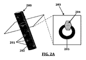
本発明における特定の態様において、少なくとも一つのケイ素材料の連続マトリックスと、例えば炭素、ポリマー、金属、セラミック、金属酸化物等の付加材料の連続的なマトリックスを含有する単独または複数のナノ複合ナノファイバーが提供される。また、ある形態においては、複数の非凝集の、少なくとも1つのケイ素材料の不連続のドメインおよび第二材料(例えば、炭素、ポリマー、金属、セラミック、金属酸化物等連続マトリックス材料)を含有する単独または複数のナノ複合ナノファイバーが提供される。特定の態様において、第二材料は、(例えば、非晶質炭素、非晶質と結晶質炭素の組み合わせを含む)炭素である。ある態様において、骨格(例えば、連続的なマトリックス材料)を含有するナノ複合ナノファイバーが提供され、骨格はここで提供されるナノ粒子を含み、骨格は炭素およびケイ素含有ナノ粒子を含有する。ある態様において、骨格は、芯マトリックス材料である。他の態様において、骨格は、例えば、ナノファイバーの少なくとも一部に沿う中空芯を含み、ナノファイバーは、図2Aに示すように、中空の中心よりもむしろマトリックス材料内に見出され、埋め込まれたナノ粒子を有する。 In certain embodiments of the invention, single or multiple nanocomposite nanofibers containing a continuous matrix of at least one silicon material and a continuous matrix of additional materials such as carbon, polymers, metals, ceramics, metal oxides, etc. Is provided. Also, in some embodiments, a single containing a plurality of non-agglomerated, at least one discontinuous domain of silicon material and a second material (eg, continuous matrix material such as carbon, polymer, metal, ceramic, metal oxide, etc.) Alternatively, a plurality of nanocomposite nanofibers are provided. In certain embodiments, the second material is carbon (eg, including amorphous carbon, a combination of amorphous and crystalline carbon). In certain embodiments, nanocomposite nanofibers are provided that contain a scaffold (eg, a continuous matrix material), the scaffold comprises nanoparticles provided herein, and the scaffold contains carbon and silicon-containing nanoparticles. In some embodiments, the scaffold is a core matrix material. In other embodiments, the skeleton includes, for example, a hollow core along at least a portion of the nanofibers, and the nanofibers are found and embedded within the matrix material rather than the hollow center, as shown in FIG. 2A. With nanoparticles.
幾つかの態様では、明細書に記載のナノファイバーの骨格またはマトリックス材料は、非晶質炭素を含有する。特定の態様において、本発明に記載のナノファイバーの骨格またはマトリックス材料は、結晶質炭素(例えば、グラファイトおよび/またはグラフェン)を含む。さらなる態様において、本発明に記載のナノファイバーの骨格またはマトリックス材料は、非晶質炭素および結晶性炭素を含む。 In some embodiments, the nanofiber scaffolds or matrix materials described herein contain amorphous carbon. In certain embodiments, the nanofiber framework or matrix material according to the present invention comprises crystalline carbon (eg, graphite and / or graphene). In a further embodiment, the nanofiber scaffold or matrix material according to the present invention comprises amorphous carbon and crystalline carbon.
いくつかの態様において、少なくとも1つの連続骨格と、少なくとも1つの連続骨格内に組み込まれた少なくとも一つの不連続なナノ粒子とを含有するナノ複合であって、(a)少なくとも1つの連続骨格は、ケイ素を含む第一材料;およびケイ素を有さない第二材料の1つを含み、(b)少なくとも1つの不連続なナノ粒子は、ケイ素を含む第一材料;およびケイ素を有さない第二材料のうちの他方を含有するナノ複合材料を提供する。特定の実施態様において、ケイ素を有さない第二材料は、ケイ素を有さない炭素を含有する第二材料を含む。 In some embodiments, a nanocomposite comprising at least one continuous skeleton and at least one discontinuous nanoparticle incorporated within the at least one continuous skeleton, wherein (a) the at least one continuous skeleton is A first material comprising silicon; and one of the second materials without silicon; and (b) at least one discontinuous nanoparticle comprising a first material comprising silicon; and a first material without silicon. Nanocomposites containing the other of the two materials are provided. In certain embodiments, the second material without silicon comprises a second material containing carbon without silicon.
特定の態様では、提供されるナノファイバーのナノ粒子または不連続のドメインは、ゼロ酸化状態のケイ素を含む。さらなる実施態様において、提供されるナノファイバーのナノ粒子又は不連続のドメインは、ゼロ酸化状態(例えば、元素状ケイ素)と酸化状態のケイ素(例えば二酸化ケイ素)を含有する。特定の態様において、ナノ粒子は、元素状ケイ素および二酸化ケイ素を含む。より具体的な態様において、ナノ粒子は、元素状ケイ素対二酸化ケイ素の比が5:1(例えば、10:1、20:1、30:1など)である元素ケイ素と二酸化ケイ素を含有する。図6は、本発明に記載のナノファイバーの一部に存在する特定のケイ素ナノ粒子の結晶性を示す。 In certain embodiments, the provided nanofiber nanoparticles or discontinuous domains comprise silicon in a zero oxidation state. In further embodiments, provided nanofiber nanoparticles or discontinuous domains contain a zero oxidation state (eg, elemental silicon) and an oxidation state silicon (eg, silicon dioxide). In certain embodiments, the nanoparticles comprise elemental silicon and silicon dioxide. In a more specific embodiment, the nanoparticles contain elemental silicon and silicon dioxide with an elemental silicon to silicon dioxide ratio of 5: 1 (eg, 10: 1, 20: 1, 30: 1, etc.). FIG. 6 shows the crystallinity of certain silicon nanoparticles present in some of the nanofibers described in the present invention.
特定の態様では、本発明に係るナノファイバーの不連続のドメインまたはナノ粒子は、100nm未満の平均直径を有する。特定の態様において、ナノ粒子またはドメインは、10nm〜80nmの平均直径を有する。より具体的な態様では、ナノ粒子またはドメインは、20nm〜60nmの平均直径を有する。 In a particular embodiment, the nanofiber discontinuous domains or nanoparticles according to the invention have an average diameter of less than 100 nm. In certain embodiments, the nanoparticles or domains have an average diameter of 10 nm to 80 nm. In a more specific aspect, the nanoparticles or domains have an average diameter of 20 nm to 60 nm.
いくつかの態様において、ナノ粒子又は不連続のドメインの大部分は、少なくとも50%の炭素被覆された表面を備える。特定の態様において、ナノ粒子又は不連続のドメインの大部分は、少なくとも75%の炭素被覆された表面を備える。特定の態様において、ナノ粒子又は不連続のドメインの大部分は、少なくとも85%の炭素被覆された表面を備える。さらにより特定の態様において、ナノ粒子又は不連続のドメインの大部分は、少なくとも90%の炭素被覆された表面を備える。さらにより具体的な態様において、ナノ粒子又は不連続のドメインの大部分は、少なくとも95%の炭素被覆された表面を備える。いくつかの特定の態様では、少なくとも50%、少なくとも60%、少なくとも70%、少なくとも80%、少なくとも90%、または少なくとも95%のナノ粒子又は不連続ドメインは、少なくとも50%、少なくとも75%、少なくとも85%、少なくとも90%、または少なくとも95%の炭素被覆された表面を備える。 In some embodiments, the majority of the nanoparticles or discrete domains comprise at least 50% carbon-coated surfaces. In certain embodiments, the majority of the nanoparticles or discrete domains comprise at least 75% carbon-coated surfaces. In certain embodiments, the majority of the nanoparticles or discrete domains comprise at least 85% carbon-coated surfaces. In an even more particular embodiment, the majority of the nanoparticles or discontinuous domains comprise at least 90% carbon coated surface. In an even more specific aspect, the majority of the nanoparticles or discontinuous domains comprise at least 95% carbon-coated surfaces. In some specific embodiments, at least 50%, at least 60%, at least 70%, at least 80%, at least 90%, or at least 95% of the nanoparticles or discontinuous domains are at least 50%, at least 75%, at least With 85%, at least 90%, or at least 95% carbon-coated surface.
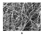
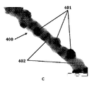
特定の態様では、ナノ粒子またはドメインは、非凝集である。例えば図4は、マトリックスまたはその骨格402に埋め込まれた非凝集ナノ粒子401を含むナノファイバー400を示している(例えば、本発明に記載したガスアシスト電界紡糸法に従って調製した)。一方、図5(パネルA,B,CおよびD)は、ナノファイバー中に凝集したナノ粒子を示している(非ガスアシスト電界紡糸法に従って調製した)。ある態様では、ナノ粒子の40%未満が凝集している(例えば、TEMによる、任意の適切な方法で測定される)。特定の態様において、ナノ粒子の30%未満が凝集する。より具体的な態様において、ナノ粒子の25%未満が凝集する。さらにより具体的な態様では、ナノ粒子の20%未満が凝集する。さらにより具体的な態様において、ナノ粒子の10%未満が凝集する。より具体的な態様において、ナノ粒子の5%未満が凝集する。
In certain embodiments, the nanoparticles or domains are non-aggregated. For example, FIG. 4 shows a
いくつかの態様では、ナノ粒子またはドメインは、ナノファイバーの全長に沿って分散している。 In some embodiments, the nanoparticles or domains are dispersed along the entire length of the nanofiber.
幾つかの態様では、本発明におけるナノファイバーは、平均して、25重量%未満の炭素を含有する(例えば、TGAまたは元素分析によって測定される)。特定の態様において、本発明におけるナノファイバーは、平均して、1重量%〜25重量%の炭素を含有する。より具体的な態様では、ナノファイバーは、平均して、5重量%〜25重量%の炭素を含む。さらにより具体的な態様では、ナノファイバーは、平均して、5重量%〜20重量%の炭素を含む。さらにより特定の態様において、ナノファイバーは、平均して、10重量%〜20重量%の炭素を含む。いくつかの態様では、ナノファイバーは、平均して、少なくとも50元素重量%のケイ素(例えばケイ素および/またはシリカの形態)を含有する。特定の態様において、ナノファイバーは、平均して、少なくとも60元素重量%のケイ素(例えばケイ素および/またはシリカの形態)を含有する。より具体的な態様では、ナノファイバーは、平均して、少なくとも70元素重量%のケイ素(例えばケイ素および/またはシリカの形態)を含有する。さらにより特定の態様において、ナノファイバーは、平均して、少なくとも75元素重量%のケイ素(例えばケイ素および/またはシリカの形態)を含有する。さらにより特定の態様において、ナノファイバーは、平均して、少なくとも80元素重量%のケイ素(例えばケイ素および/またはシリカの形態)を含有する。
さらにより特定の態様において、ナノファイバーは、平均して、少なくとも85元素重量%のケイ素(例えばケイ素および/またはシリカの形態)を含有する。いくつかの態様では、本発明に係るナノファイバーは、平均して少なくとも50重量%のケイ素を含有する(すなわち、ゼロ酸化/元素ケイ素)。特定の態様において、本発明に係るナノファイバーは、平均して少なくとも60重量%のケイ素を含有する(すなわち、ゼロ酸化/元素ケイ素)。さらにより具体的な態様では、本発明に係るナノファイバーは、平均して少なくとも70重量%のケイ素を含有する(すなわち、ゼロ酸化/元素ケイ素)。さらにより特定の態様において、本発明に係るナノファイバーは、平均して少なくとも75重量%のケイ素を含有する(すなわち、ゼロ酸化/元素ケイ素)。より具体的な態様では、本発明に係るナノファイバーは、平均して少なくとも80重量%のケイ素を含有する(すなわち、ゼロ酸化/元素ケイ素)。さらにより特定の態様において、本発明に係るナノファイバーは、平均して少なくとも85重量%のケイ素を含有する(すなわち、ゼロ酸化/元素ケイ素)。
In some embodiments, the nanofibers in the present invention contain, on average, less than 25 wt% carbon (eg, as measured by TGA or elemental analysis). In certain embodiments, the nanofibers in the present invention contain, on average, 1 wt% to 25 wt% carbon. In a more specific aspect, the nanofibers comprise, on average, 5 wt% to 25 wt% carbon. In an even more specific aspect, the nanofibers comprise on
In an even more particular embodiment, the nanofibers contain, on average, at least 85 elemental weight percent silicon (eg, in the form of silicon and / or silica). In some embodiments, the nanofibers according to the present invention contain on average at least 50% by weight silicon (ie, zero oxide / elemental silicon). In a particular embodiment, the nanofibers according to the invention contain on average at least 60% by weight of silicon (ie zero oxide / elemental silicon). In an even more specific embodiment, the nanofibers according to the invention contain on average at least 70% by weight of silicon (ie zero oxide / elemental silicon). In an even more particular embodiment, the nanofibers according to the invention contain on average at least 75% by weight silicon (ie zero oxide / elemental silicon). In a more specific embodiment, the nanofibers according to the present invention contain on average at least 80% by weight silicon (ie zero oxide / elemental silicon). In an even more particular embodiment, the nanofibers according to the invention contain on average at least 85% by weight of silicon (ie zero oxide / elemental silicon).
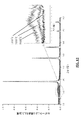
ある態様において、本発明に係るナノファイバーは、X線回折において以下の三点以上で2θピークを有する:28.37°±0.03、47.20°±0.03、56.09°±0.03、69.02°±0.03および76.37°±0.03。特定の態様において、本発明に係るナノファイバーのXRDピークは、このようなピークの少なくとも4つを有している。より具体的な態様において、本発明に係るナノファイバーのXRDピークは、このようなピークの5個全てを有している。他の態様において、本発明に係るナノファイバーのXRDピークは、このようなピークの少なくとも2つを有している。本発明に係るナノファイバーのXRDピークはこのようなピークの少なくとも二つを有している。いくつかの態様において、本発明で提供されるナノファイバーは、図6のXRDパターンを有する(例えば、類似または同一のものが、図12の変形例に生じる)。 In one embodiment, the nanofiber according to the present invention has 2θ peaks in X-ray diffraction at three or more of the following points: 28.37 ° ± 0.03, 47.20 ° ± 0.03, 56.09 ° ± 0.03, 69.02 ° ± 0.03 and 76.37 ° ± 0.03. In certain embodiments, the XRD peaks of the nanofibers according to the present invention have at least four such peaks. In a more specific embodiment, the XRD peak of the nanofiber according to the present invention has all five such peaks. In another embodiment, the XRD peak of the nanofiber according to the present invention has at least two of such peaks. The XRD peak of the nanofiber according to the present invention has at least two such peaks. In some embodiments, nanofibers provided by the present invention have the XRD pattern of FIG. 6 (eg, similar or identical occurs in the variation of FIG. 12).
特定の態様では、本発明に係るナノファイバー(またはそのようなナノファイバーを含有する陽極)は、0.1Cでの第1サイクルで少なくとも1500mAh/gの比エネルギー容量を有する。特定の態様において、本発明に係るナノファイバー(またはそのようなナノファイバーを含有する陽極)は、0.1Cでの最初のサイクルで少なくとも2000mAh/gの比エネルギー容量を有する。いくつかの態様において、本発明に係るナノファイバー(またはそのようなナノファイバーを含有する陽極)は、0.1Cでの98回目のサイクルで少なくとも250mAh/gの比エネルギー容量を有する。特定の態様において、本発明に係るナノファイバー(またはそのようなナノファイバーを含有する陽極)は、0.1Cでの98回目のサイクルで少なくとも400mAh/gの比エネルギー容量を有する。 In a particular embodiment, the nanofibers according to the invention (or the anode containing such nanofibers) have a specific energy capacity of at least 1500 mAh / g in the first cycle at 0.1C. In certain embodiments, nanofibers according to the present invention (or an anode containing such nanofibers) have a specific energy capacity of at least 2000 mAh / g with an initial cycle at 0.1C. In some embodiments, nanofibers according to the present invention (or an anode containing such nanofibers) have a specific energy capacity of at least 250 mAh / g at the 98th cycle at 0.1 C. In a particular embodiment, the nanofibers according to the invention (or the anode containing such nanofibers) have a specific energy capacity of at least 400 mAh / g at the 98th cycle at 0.1 C.
本発明におけるケイ素は、基本的なケイ素の特定の開示を含み、ケイ素材料は、ケイ素、酸化ケイ素、ケイ素合金、等を含む。本発明におけるケイナノ粒子には、基本的なケイ素を含有するナノ粒子の特定の開示を含む(他のケイ素材料を含む、他の任意のものが存在する)。 Silicon in the present invention includes specific disclosures of basic silicon, and silicon materials include silicon, silicon oxide, silicon alloys, and the like. Silica nanoparticles in the present invention include specific disclosures of basic silicon-containing nanoparticles (there are any others, including other silicon materials).
特定の態様において、本発明は、少なくとも1つのケイ素材料の連続マトリックスおよび(例えば、ケイ素材料連続マトリックスまたは第2連続マトリックスにおける)少なくとも一つのケイ素材料の複数で非凝集の不連続ドメインを含有する単数または複数のナノ複合ナノファイバーを提供する。 In certain embodiments, the invention includes a singular containing a continuous matrix of at least one silicon material and a plurality of non-agglomerated discontinuous domains of at least one silicon material (eg, in a silicon material continuous matrix or a second continuous matrix). Alternatively, a plurality of nanocomposite nanofibers are provided.
いくつかの態様において、非凝集で不連続のドメインは、少なくとも一つのケイ素材料を含有する非凝集ナノ粒子を含む。特定の態様では、ナノファイバーは、隣接する500nm長のナノファイバーよりも、ナノファイバーの長さに沿う500nm長のセグメントに沿って20倍高いドメイン濃度を含まない。いくつかの態様において、不連続のドメインは、ゼロの酸化状態を有するケイ素を少なくとも50重量%(例えば90重量%)含有する。特定の態様において、不連続のドメインは、ゼロの酸化状態を有するケイ素(元素ケイ素)を少なくとも95重量%含有する。 In some embodiments, the non-agglomerated discontinuous domain comprises non-aggregated nanoparticles containing at least one silicon material. In certain embodiments, the nanofibers do not contain a domain concentration that is 20 times higher along 500 nm long segments along the length of the nanofibers than adjacent 500 nm long nanofibers. In some embodiments, the discontinuous domains contain at least 50% (eg, 90% by weight) silicon having a zero oxidation state. In certain embodiments, the discontinuous domains contain at least 95% by weight silicon (elemental silicon) having a zero oxidation state.
特定の態様では、ナノ複合ナノファイバーは、同軸層状ナノファイバー、芯および少なくとも部分的に芯を取り囲む鞘を含むナノファイバーである。特定の態様において、芯は、ケイ素材料を含む。さらなる又は代替的な態様において、鞘は、ケイ素材料を含む。 In certain embodiments, the nanocomposite nanofiber is a nanofiber comprising a coaxial layered nanofiber, a core and a sheath at least partially surrounding the core. In certain embodiments, the core includes a silicon material. In further or alternative embodiments, the sheath includes a silicon material.
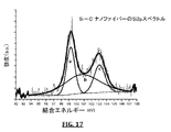
特定の態様では、本発明に係るナノファイバーは、(例えば、平均して)少なくとも20重量%のケイ素含有材料を含む。特定の態様において、本発明に係るナノファイバーは、(例えば、平均して)少なくとも30重量%のケイ素含有材料を含む。本発明に係るナノファイバーは、(例えば、平均して)少なくとも50重量%のケイ素含有材料を含む。本発明に係るナノファイバーは、(例えば、平均して)少なくとも70重量%のケイ素含有材料を含む。本発明に係るナノファイバーは、(例えば、平均して)90重量%以下のケイ素含有材料を含む。特定の態様において、ケイ素材料は元素ケイ素である。他の特定の態様では、ケイ素材料は、元素ケイ素(すなわち、ゼロ酸化状態のケイ素)とケイ素酸化物(例えば、二酸化ケイ素)を含む。他の特定の態様では、ケイ素材料は、元素珪素(すなわち、ゼロ酸化状態のケイ素)、酸化ケイ素、および炭化ケイ素を含む。図17は、本発明に記載のケイ素/炭素ナノ複合ナノファイバーX線光電子分光(XPS)を示す。特定の態様において、本発明に係るナノファイバーは、(例えば、平均して)少なくとも10重量%の第2材料を含有する。特定の態様において、本発明に係るナノファイバーは、(例えば、平均して)少なくとも20重量%の第2材料を含有する。より具体的な態様において、本発明に係るナノファイバーは、(例えば、平均して)少なくとも30重量%の第2材料を含有する。いくつかの態様において、本発明に係るナノファイバーは、(例えば、平均して)30重量%未満の第2材料を含有する。特定の態様において、本発明に係るナノファイバーは、(例えば、平均して)20重量%未満の第2材料を含有する。 In certain embodiments, nanofibers according to the present invention comprise (eg, on average) at least 20% by weight silicon-containing material. In certain embodiments, nanofibers according to the present invention comprise (eg, on average) at least 30% by weight silicon-containing material. The nanofibers according to the present invention comprise (eg on average) at least 50% by weight of a silicon-containing material. The nanofibers according to the present invention comprise (eg on average) at least 70% by weight of a silicon-containing material. The nanofibers according to the invention comprise (for example on average) 90% by weight or less of a silicon-containing material. In certain embodiments, the silicon material is elemental silicon. In other particular embodiments, the silicon material comprises elemental silicon (ie, zero oxidation state silicon) and silicon oxide (eg, silicon dioxide). In other particular embodiments, the silicon material comprises elemental silicon (ie, zero oxidation state silicon), silicon oxide, and silicon carbide. FIG. 17 shows a silicon / carbon nanocomposite nanofiber X-ray photoelectron spectroscopy (XPS) according to the present invention. In certain embodiments, nanofibers according to the present invention contain (eg, on average) at least 10% by weight of the second material. In certain embodiments, nanofibers according to the present invention contain (eg, on average) at least 20% by weight of the second material. In a more specific embodiment, the nanofibers according to the invention contain (for example on average) at least 30% by weight of the second material. In some embodiments, nanofibers according to the present invention contain (eg, on average) less than 30% by weight of the second material. In certain embodiments, nanofibers according to the present invention contain (eg, on average) less than 20% by weight of the second material.
具体的な態様では、本発明に係るナノファイバーは(例えば、平均して)少なくとも60重量%の(例えばケイ素およびケイ素酸化物を含む)ケイ素含有材料および少なくとも30重量%の第二材料(例えば炭素)を含有する。 In a specific embodiment, the nanofibers according to the invention comprise (eg on average) at least 60% by weight of a silicon-containing material (for example comprising silicon and silicon oxide) and at least 30% by weight of a second material (for example carbon). ).
特定の態様では、本発明に係るナノファイバーは、(例えば、平均で)少なくとも30重量%(元素ベース)のケイ素を含有する。特定の態様では、本発明に係るナノファイバーは、(例えば、平均で)少なくとも50重量%(元素ベース)のケイ素を含有する。特定の態様では、本発明に係るナノファイバーは、(例えば、平均で)少なくとも70重量%(元素ベース)のケイ素を含有する。 In a particular embodiment, the nanofibers according to the invention contain (eg on average) at least 30% by weight (element-based) silicon. In certain embodiments, nanofibers according to the present invention contain (eg, on average) at least 50 wt.% (Element based) silicon. In certain embodiments, nanofibers according to the present invention contain (eg, on average) at least 70% by weight (element based) silicon.
いくつかの態様では、第二材料は、セラミック、金属、有機ポリマー、又は炭素を含む。特定の態様において、第二材料は炭素を含む。他の特定の態様では、第二材料は、有機ポリマー、例えば、水溶性有機ポリマーを含む。他の特定の態様では、第二材料は、炭素を含む(例えば、水溶性有機高分子を炭素化した後のもの)。 In some embodiments, the second material includes a ceramic, metal, organic polymer, or carbon. In certain embodiments, the second material includes carbon. In other specific embodiments, the second material comprises an organic polymer, such as a water soluble organic polymer. In other particular embodiments, the second material comprises carbon (eg, after carbonizing a water soluble organic polymer).
特定の態様では、ナノファイバー(複数)は、1ミクロン未満(例えば、800nm未満)の平均直径を有している。いくつかの態様では、ナノファイバー(単数または複数)は、少なくとも100の平均アスペクト比を有する(例えば、少なくとも1000、又は少なくとも10,000)。いくつかの態様では、ナノファイバーは架橋されている。 In certain embodiments, the nanofibers have an average diameter of less than 1 micron (eg, less than 800 nm). In some embodiments, the nanofiber (s) have an average aspect ratio of at least 100 (eg, at least 1000, or at least 10,000). In some embodiments, the nanofibers are cross-linked.
本明細書において、本発明に記載の複数のナノ複合ナノファイバーの不織マットを含有する電極が提供される。さらに、本発明において、このような電極を備えている電池(例えばリチウムイオン電池)が提供される。より具体的な態様では、リチウムイオン電池は、初期または放電状態において、陽極、セパレータおよび負極を含有し、負極は、本発明に係るナノ複合ナノファイバーを含有し、または1または複数のこのようなナノ複合ナノファイバーを含有する不織マットを含む。 Provided herein are electrodes containing a plurality of nanocomposite nanofiber nonwoven mats according to the present invention. Furthermore, in the present invention, a battery (for example, a lithium ion battery) provided with such an electrode is provided. In a more specific aspect, the lithium ion battery contains an anode, a separator and a negative electrode in the initial or discharged state, the negative electrode contains a nanocomposite nanofiber according to the invention, or one or more such Nonwoven mats containing nanocomposite nanofibers are included.
本発明において、例えば、上述のようなナノ複合ナノファイバーの製造方法が提供され、この方法は、流体ストックの電界紡糸を含み、流体ストックは、任意の順番で、ケイ素成分、有機ポリマー、および流体を組み合わせることにより調製されるか、またはこれらを含有するものである特定の態様では、流体は水を含むか、または水性である。いくつかの態様では、有機ポリマーは水溶性ポリマーである。特定の態様では、ケイ素成分(例えば、ケイ素前駆体)対有機ポリマーの重量対重量比は、少なくとも1:2(例えば、少なくとも1:1)である。いくつかの態様では、ケイ素成分(例えば、ケイ素ナノ粒子)対有機ポリマーの重量対重量比は、少なくとも1:10(例えば、少なくとも1:5、少なくとも1:4、少なくとも1:3少なくとも1:2、少なくとも1:1、1:10〜1:1または1:5〜1:1)である。いくつかの態様では、方法はさらに、紡糸したナノファイバーを熱処理することを含む。いくつかの態様において、熱処理は、不活性条件下(例えば、ポリマーを炭化する条件下)で起こる。さらなる又は代替的な態様において、方法は、紡糸したナノファイバーを酸化することを含む(例えば、同時に熱処理をおこなう)(例えば、ポリマーを除去するために行われる)。さらなる又は代替的な態様において、方法は、(例えば、または以前に処理、例えば熱処理された)紡績ナノファイバー(例えば、同時に熱処理されたもの)の還元工程をさらに含む(例えば、金属成分の酸化を最小限にするため)。 In the present invention, for example, a method for producing a nanocomposite nanofiber as described above is provided, the method comprising electrospinning of a fluid stock, wherein the fluid stock is in any order a silicon component, an organic polymer, and a fluid. In certain embodiments, which are prepared by combining or containing these, the fluid comprises water or is aqueous. In some embodiments, the organic polymer is a water soluble polymer. In certain embodiments, the weight to weight ratio of silicon component (eg, silicon precursor) to organic polymer is at least 1: 2 (eg, at least 1: 1). In some embodiments, the weight to weight ratio of silicon component (eg, silicon nanoparticles) to organic polymer is at least 1:10 (eg, at least 1: 5, at least 1: 4, at least 1: 3 at least 1: 2). At least 1: 1, 1:10 to 1: 1 or 1: 5 to 1: 1). In some embodiments, the method further comprises heat treating the spun nanofibers. In some embodiments, the heat treatment occurs under inert conditions (eg, conditions that carbonize the polymer). In further or alternative embodiments, the method includes oxidizing the spun nanofibers (eg, performing a heat treatment at the same time) (eg, performed to remove the polymer). In further or alternative embodiments, the method further comprises a reduction step (eg, oxidation of the metal component) of (eg, or previously treated, eg, heat treated) spun nanofibers (eg, those that have been heat treated simultaneously). To minimize).
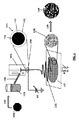
いくつかの態様では、方法は、ガスアシストにより流体ストックを電界紡糸することを含む。具体的な態様では、方法は、同軸ガスアシストを用いて流体ストックを電界紡糸することを含む。いくつかの態様では、ガスアシストは、ガス(例えば、高速ガス)を流体ストックが電界紡糸される共通軸に沿ってまたは周囲に(すなわち、同軸上に)吹き込むことにより行われる。いくつかの態様では、電界紡糸流体ストックと同軸に隣接し、周囲または沿って流れる高速ガスを用いて流体ストックは電界紡糸される(例えば、流体ストックが電界紡糸される軸に沿って1、5または10度以内である)。図1及び図3は、流体ストックの同軸ガスアシスト電界紡糸を提供するための例示的なシステムを示す。 In some aspects, the method includes electrospinning the fluid stock with gas assist. In a specific aspect, the method includes electrospinning a fluid stock using coaxial gas assist. In some aspects, gas assist is performed by blowing gas (eg, high velocity gas) along or around (ie, coaxially) a common axis along which the fluid stock is electrospun. In some aspects, the fluid stock is electrospun using a high velocity gas that is coaxially adjacent and flows around or along the electrospun fluid stock (eg, 1, 5 along the axis along which the fluid stock is electrospun). Or within 10 degrees). 1 and 3 illustrate an exemplary system for providing coaxial gas assisted electrospinning of fluid stock.
幾つかの態様では、ケイ素成分は(例えば、ゼロ酸化状態のケイ素を含む)ケイ素含有ナノ粒子である。他の態様では、ケイ素成分は、ケイ素前駆体(例えば、ケイ素アセテート)である。特定の態様において、ケイ素前駆体は、ケイ素カルボキシレート(例えば、ケイ素アセテート)、ハロゲン化ケイ素(例えば、塩化ケイ素)、ケイ素アルコキシド、またはそれらの組み合わせを含む。特定の態様において、ポリマーは、求核性である。いくつかの態様において、ポリマーは、ポリビニルアルコール(PVA)、ポリ酢酸ビニル(PVAc)、ポリエチレンオキシド(PEO)、ポリビニルエーテル、ポリビニルピロリドン(PVP)、ポリグリコール酸、ヒドロキシエチルセルロース(HEC)、エチルセルロース、セルロースエーテル、ポリアクリル酸、ポリイソシアネート、またはあるこれらの組み合わせである。 In some embodiments, the silicon component is silicon-containing nanoparticles (eg, including zero-oxidized state silicon). In other embodiments, the silicon component is a silicon precursor (eg, silicon acetate). In certain embodiments, the silicon precursor comprises a silicon carboxylate (eg, silicon acetate), a silicon halide (eg, silicon chloride), a silicon alkoxide, or a combination thereof. In certain embodiments, the polymer is nucleophilic. In some embodiments, the polymer is polyvinyl alcohol (PVA), polyvinyl acetate (PVAc), polyethylene oxide (PEO), polyvinyl ether, polyvinyl pyrrolidone (PVP), polyglycolic acid, hydroxyethyl cellulose (HEC), ethyl cellulose, cellulose Ether, polyacrylic acid, polyisocyanate, or some combination thereof.
いくつかの態様では、方法はさらに、ケイ素成分、ポリマーおよび流体媒体(例えば、水または水溶液)を任意の順序で組み合わせて、流体ストックを調製することを含む。さらなる態様では、流体ストックは、少なくとも一つの非ケイ素金属前駆体を含む(例えば、任意の適切な順序で、他の成分と非ケイ素金属前駆体を組み合わせることにより調製される)。特定の態様において、非ケイ素金属前駆体は、非限定的な例として、モリブデン前駆体、ニオブ前駆体、タンタル前駆体、タングステン前駆体、鉄前駆体、ニッケル前駆体、銅前駆体、コバルト前駆体、マンガン前駆体、チタン前駆体、バナジウム前駆体、酸化バナジウム前駆体、クロム前駆体、ジルコニウム前駆体、イットリウム前駆体、またはそれらの組み合わせを含む。いくつかの態様では、流体ストック中の(ケイ素および非ケイ素金属を含む)金属濃度は、(ケイ素を含む)金属が取り得る形状に関係なく、少なくとも200mM(例えば、少なくとも250mM、または少なくとも300mM)であり、モル数は金属原子のモル数に基づく。 In some embodiments, the method further comprises preparing a fluid stock by combining the silicon component, polymer and fluid medium (eg, water or aqueous solution) in any order. In further embodiments, the fluid stock comprises at least one non-silicon metal precursor (eg, prepared by combining the non-silicon metal precursor with other components in any suitable order). In certain embodiments, the non-silicon metal precursor includes, by way of non-limiting example, a molybdenum precursor, niobium precursor, tantalum precursor, tungsten precursor, iron precursor, nickel precursor, copper precursor, cobalt precursor. , Manganese precursors, titanium precursors, vanadium precursors, vanadium oxide precursors, chromium precursors, zirconium precursors, yttrium precursors, or combinations thereof. In some embodiments, the metal concentration (including silicon and non-silicon metals) in the fluid stock is at least 200 mM (eg, at least 250 mM, or at least 300 mM), regardless of the shape that the metal (including silicon) can take. Yes, the number of moles is based on the number of moles of metal atoms.
明細書に記載の単一のナノファイバーの特性には記載された平均的な特徴を有する複数のナノファイバーの開示を含む。同様に、明細書に記載の複数のナノファイバーの特性には記載された平均的な特徴を有する単一のナノファイバーの開示を含む。 The properties of the single nanofiber described in the specification include disclosure of a plurality of nanofibers having the described average characteristics. Similarly, the properties of the plurality of nanofibers described in the specification include disclosure of a single nanofiber having the described average characteristics.
本発明の新規な特徴は、添付の特許請求の範囲に具体的に記載されている。 The novel features of the invention are set forth with particularity in the appended claims.
本発明の特徴および利点のより良い理解は、本発明の原理が利用される例示的な態様、及び添付図面ならびに以下の詳細な説明を参照することによって得られるであろう。 A better understanding of the features and advantages of the present invention will be obtained by reference to the illustrative embodiments in which the principles of the invention are utilized, and the accompanying drawings and the following detailed description.
本発明に係るケイ素含有ナノ複合ナノファイバーおよびナノファイバーマットおよびケイ素含有ナノ複合ナノファイバーおよびナノファイバーマットの製造方法が提供される。いくつかの態様では、(例えば本発明に記載される、複数の、ナノファイバーの、ナノファイバーマットの、および本発明に係る製造方法の)ナノファイバーは、)第一材料と第二材料を含有し、第一材料はケイ素含有材料を含む。さらなる態様において、第一の材料、第二の材料、または両方がファイバー内に連続マトリックスを形成する。特定の態様において、第一材料および第二材料は、ナノファイバー内の連続マトリックス材料を形成する。他の特定の態様では、第一の材料は、ナノファイバー内に不連続な複数のドメインを含む。より具体的な態様では、第二材料はナノファイバー内の連続的なマトリックス材料である。 There are provided silicon-containing nanocomposite nanofibers and nanofiber mats and methods for producing silicon-containing nanocomposite nanofibers and nanofiber mats according to the present invention. In some embodiments, a nanofiber (eg, a plurality of nanofibers, of a nanofiber mat, and of a manufacturing method according to the present invention described in the present invention) comprises a first material and a second material. The first material includes a silicon-containing material. In further embodiments, the first material, the second material, or both form a continuous matrix within the fiber. In certain embodiments, the first material and the second material form a continuous matrix material within the nanofiber. In other particular embodiments, the first material includes a plurality of discontinuous domains within the nanofiber. In a more specific embodiment, the second material is a continuous matrix material within the nanofibers.
いくつかの態様では、本発明に係るナノファイバーは、同軸上に積層されたナノファイバーであり、ナノファイバーは、芯と、少なくとも部分的に芯を取り囲む鞘とを含む。いくつかの態様では、鞘は、ナノファイバーの全長に沿って走る。他の態様では、鞘は、ナノファイバーの少なくとも一部に沿って走る。特定の態様において、芯は、ケイ素材料を含み、鞘は第二材料を含む。他の態様では、鞘はケイ素材料を含み、芯は第二材料を含む。特定の態様において、第二材料は第二のケイ素材料である(すなわち、鞘と芯の両方が同一または異なっていてもよく、ケイ素材料を含む)。他の態様では、第二材料はケイ素不含材料である。 In some embodiments, nanofibers according to the present invention are coaxially laminated nanofibers, the nanofiber including a core and a sheath at least partially surrounding the core. In some embodiments, the sheath runs along the entire length of the nanofiber. In other embodiments, the sheath runs along at least a portion of the nanofiber. In certain embodiments, the core includes a silicon material and the sheath includes a second material. In other embodiments, the sheath includes a silicon material and the core includes a second material. In certain embodiments, the second material is a second silicon material (ie, both the sheath and the core may be the same or different, including a silicon material). In other embodiments, the second material is a silicon-free material.
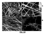
図1は、ナノ複合ナノファイバーを含有する本発明に係るナノファイバー108を示している。いくつかの例では、ナノ複合ナノファイバーは、第一および第二の連続マトリックス材料が同軸上に積層される、第一及び第二連続マトリックス材料を含む。
特定の態様では、第一(ケイ素含有)材料は、同軸上に積層されたナノファイバー108の芯114を形成し(断面図111に図示し、所望によるニードル装置の構成を示す)、
第二材料が少なくとも部分的に芯114を取り囲む層113を形成する(例えば、外層112が存在しない)。他の特定の態様では、第二材料は、同軸上の層状ナノファイバー115の芯114を形成し(断面図111に図示)、第一(ケイ素含有)材料は、少なくとも部分的に芯114を取り囲む層113を形成する。いくつかの例では、ナノファイバーは、第三の同軸層112と共に2つの層を同軸上に電界紡糸することにより製造される。いくつかの態様では、第三の同軸層112は、第三のマトリックス材料を含む。他の態様では、第三の同軸層112は、空気、例えば電界紡糸法を補助するガスなどを含む。さらに、いくつかの態様において、芯114は、ケイ素材料を含む外層112および/または113の一方または両方を有し、必要に応じて中空である。
FIG. 1 shows a
In a particular embodiment, the first (silicon-containing) material forms the
The second material forms a
図1はまた、本発明に記載の方法の例示的なシステムまたは概略図を示し、特に、(例えば、同軸ガスアシスト電界紡糸法による)同軸層状ナノ複合ナノファイバーを製造するためのシステムまたはプロセスを示すいくつかの例において、第一の流体ストック104(例えば、ケイ素成分とポリマーを含む)が、ケイ素成分(例えば、ケイ素前駆体又はナノ粒子)101と組み合わせること(102)により調製される。いくつかの態様では、流体ストックは、ニードル装置106を備えた電界紡糸装置105に供給される(104)。いくつかの態様では、流体ストック103は、第二の流体ストック(図示せず)と共に電界紡糸される。いくつかの例では、流体ストックと第二の流体ストックは、ニードル装置106を介して、所望により電界紡糸される、111に示される任意の断面形状を示す。いくつかの例では、流体ストックは、任意の層112、113、または114の何れか1つを介して電界紡糸される。特定の例において、第二の流体ストックは、存在する場合には、層112,113、または114の他のいずれかを介して電界紡糸される。例えば、二層ナノ複合ナノファイバーに関して、流体ストックと第二の流体ストックは、114および113に対応するニードルを介して電界紡糸され、ガスが112に対応するニードルを介して提供され、例えば、ガスアシスト電界紡糸法又はシステムが提供される。いくつかの態様では、第一流体、第二流体ストック(例えば、第二の金属前駆体および第二ポリマー、第二の前駆体および第一のものと同一または異なる独立した高分子を含む)、および第三の流体(例えば、気体または第三の流体ストック)が112、113、および114に対応するニードルの何れかを介して電界紡糸される。流体ストックは、任意の装置、例えばシリンジ105またはポンプにより、電界紡糸装置(例えば、そこに供給される電圧、例えば、噴流を生成するために液体ポリマーまたはポリマー溶液の表面張力に打ち勝つのに十分な電圧で電界紡糸ニードル装置)に提供できる。ガスは、任意の供給源(例えば、空気ポンプ)から電界紡糸ニードル装置106、111に提供されてもよい。111は、同軸ニードル装置または同軸層状ナノファイバーの断面の一例を表している。例えば、例示的な同軸ニードルは、外部鞘管(112で表される)、少なくとも一つの中間管(113で表され、所望によりに存在しない)、および芯管(114で表される)を含む。特定の態様において、そのような管は(例えば、互いに5度以内に整列され)共通の軸に沿って整列している。いくつかの例では、管はわずかにオフセットされているが、チューブの角度が実質的に整列される(例えば、互いに5度以内である)。電界紡糸ジェット115は、紡糸したままの(ハイブリッドまたはナノ複合)ナノファイバー108のようにコレクタ107に集められ、それを、必要に応じて熱処理し(109)焼成ナノファイバー110を生成する。二重層ニードル装置111が、ポリマーとケイ素ナノ粒子を含有する流体ストックを電界紡糸する(例えば、流体ストックは114に対応するニードルを介して提供され、113に対応するニードルは存在せず、ガスは112に対応するニードルを介して供給される)ために使用される場合、ポリマーナノ複合ナノファイバー中のケイ素ナノ粒子が生成し、熱処理(例えば、不活性条件下)により、炭素複合材料ナノファイバー中に(例えば、非凝集)ケイ素ナノ粒子を製造する。
FIG. 1 also shows an exemplary system or schematic diagram of the method described in the present invention, in particular a system or process for producing coaxial layered nanocomposite nanofibers (eg, by coaxial gas-assisted electrospinning). In some examples shown, a first fluid stock 104 (eg, comprising a silicon component and a polymer) is prepared by combining (102) with a silicon component (eg, silicon precursor or nanoparticle) 101. In some aspects, the fluid stock is supplied 104 to an
いくつかの態様では、本明細書に記載されるガスアシスト電界紡糸プロセス又は装置は、電界紡糸流体ストックと同じ軸に沿ったガスの流れを提供するように構成された装置を提供する。いくつかの例では、そのガス(またはガスニードル)が流体ストック(または流体ストックニードル)と同じ軸に沿って設けられている(および、例えば、それに隣接する)。特定の例において、ガス(またはガスニードル)は、流体ストック(または流体ストックニードル)と同軸に設けられている。図3は、同軸電界紡糸装置300を示す。同軸のニードル装置は、内ニードル301と外ニードル302を含み、両ニードルは同様の軸303の周りに整列している(5度、3度、1度等で整列する)。(図1に示すように、例えば、)いくつかの態様では、更なる同軸のニードルは、軸303の周りに整列されたニードル301と302の周囲、内部または間に所望により配置されてもよい。いくつかの例では、ニードルの終端は、必要に応じてをオフセットしている(304)。
In some aspects, the gas-assisted electrospinning process or apparatus described herein provides an apparatus configured to provide a flow of gas along the same axis as the electrospun fluid stock. In some examples, the gas (or gas needle) is provided along (and, for example, adjacent to) the same axis as the fluid stock (or fluid stock needle). In a particular example, the gas (or gas needle) is provided coaxially with the fluid stock (or fluid stock needle). FIG. 3 shows a
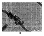
幾つかの態様では、本発明に係るナノ複合ナノファイバーは、(i)ケイ素材料(例えば、ケイ素)、および(ii)連続マトリックス材料(例えば、セラミック、金属、または炭素)を含有する。特定の態様では、連続マトリックスは、連続芯マトリックスである(例えば、中空管ではない)。いくつかの態様において、ケイ素材料は、ナノ複合ナノファイバーの個別の不連続ドメインを形成する。いくつかの特定の態様では、ケイ素材料ドメインは、非凝集である。いくつかの態様において、ケイ素材料は、ケイ素を含むナノ粒子である。特定の態様では、ケイ素不連続ドメイン材料(例えば、ケイ素ナノ粒子)は、図2、図4または図9に示すような、連続マトリックス材料内(例えば、連続的なマトリックス材料/骨格材料内)に埋め込まれている。 In some embodiments, a nanocomposite nanofiber according to the present invention contains (i) a silicon material (eg, silicon), and (ii) a continuous matrix material (eg, ceramic, metal, or carbon). In certain embodiments, the continuous matrix is a continuous core matrix (eg, not a hollow tube). In some embodiments, the silicon material forms discrete discrete domains of nanocomposite nanofibers. In some specific embodiments, the silicon material domain is non-aggregated. In some embodiments, the silicon material is a nanoparticle comprising silicon. In certain embodiments, the silicon discontinuous domain material (eg, silicon nanoparticles) is within a continuous matrix material (eg, within a continuous matrix / framework material) as shown in FIG. 2, FIG. 4, or FIG. Embedded.
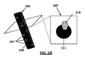
図2(a)は、(i)中空芯、(ii)鞘層中のケイ素材料の不連続ドメイン201、および(ii) 鞘層中の連続芯マトリックス202を含有するケイ素ナノ複合ナノファイバー200を示している。断面図203に示すように、ケイ素材料の不連続のドメイン204は、ナノ複合ナノファイバーの芯205に浸透できる。図2Bは、(ii) 連続的な芯マトリックス層208上/内の(i) ケイ素材料の不連続のドメイン207を含有するケイ素ナノ複合ナノファイバー206を示している。断面図209に示すように、ケイ素材料の不連続のドメイン210は、ナノ複合ナノファイバーの芯211に浸透することができる。いくつかの例では、ナノ複合ナノファイバーはナノファイバーの表面上にケイ素材料を含む。そしていくつかの例では、ナノファイバーは、芯マトリックス材料内に完全に埋め込まれたケイ素材料の不連続のドメインを含有するか、更に含有する。
FIG. 2 (a) shows a
特定の態様では、本発明に記載のナノ複合ナノファイバーの連続マトリックス材料は、ナノ複合ナノファイバーの長さの少なくとも一部にわたって連続している。いくつかの態様では、連続的なマトリックス材料は、(例えば、複数のナノファイバーでは平均して)ナノファイバーの長さの少なくとも10%に沿って施される。より具体的な態様では、連続的なマトリックス材料は、(例えば、複数のナノファイバーでは平均して)ナノファイバーの長さの少なくとも25%に沿って施される。さらにより特定の態様において、連続的なマトリックス材料は、(例えば、複数のナノファイバーでは平均して)ナノファイバーの長さの少なくとも50%に沿って施される。さらにより具体的な態様において、連続的なマトリックス材料は、(例えば、複数のナノファイバーでは平均して)ナノファイバーの長さの少なくとも75%に沿って施される。いくつかの態様では、連続マトリックスは、(複数のナノファイバーでは平均して)ナノファイバーの長さの少なくとも50%、少なくとも60%、少なくとも70%、少なくとも80%、少なくとも90%、少なくとも95%、少なくとも98%、または少なくとも99%の長さに沿って施される。いくつかの態様では、連続的なマトリックス材料は、(例えば、複数のナノファイバーでは平均して)ナノファイバーの長さの少なくとも1ミクロンに沿って施される。より具体的な態様では、連続的なマトリックス材料は、(例えば、複数のナノファイバーでは平均して)ナノファイバーの長さの少なくとも10ミクロンに沿って施される。さらにより具体的な態様では、連続的なマトリックス材料は、(例えば、複数のナノファイバーでは平均して)ナノファイバーの長さの少なくとも100ミクロンに沿って施される。さらにより具体的な態様において、連続的なマトリックス材料は、(例えば、複数のナノファイバーでは平均して)ナノファイバーの長さの少なくとも1mmに沿って施される。 In certain embodiments, the nanocomposite nanofiber continuous matrix material described in the present invention is continuous over at least a portion of the length of the nanocomposite nanofiber. In some embodiments, the continuous matrix material is applied along at least 10% of the length of the nanofibers (eg, on average for the plurality of nanofibers). In a more specific aspect, the continuous matrix material is applied along at least 25% of the length of the nanofibers (eg, on average for a plurality of nanofibers). In an even more specific embodiment, the continuous matrix material is applied along at least 50% of the length of the nanofibers (eg, on average for the plurality of nanofibers). In an even more specific embodiment, the continuous matrix material is applied along at least 75% of the length of the nanofibers (eg, on average for the plurality of nanofibers). In some embodiments, the continuous matrix is (on average for the plurality of nanofibers) at least 50%, at least 60%, at least 70%, at least 80%, at least 90%, at least 95% of the length of the nanofibers, It is applied along a length of at least 98%, or at least 99%. In some embodiments, the continuous matrix material is applied along at least 1 micron of the length of the nanofiber (eg, on average for a plurality of nanofibers). In a more specific aspect, the continuous matrix material is applied along at least 10 microns of nanofiber length (eg, on average for a plurality of nanofibers). In an even more specific aspect, the continuous matrix material is applied along at least 100 microns of nanofiber length (eg, on average for a plurality of nanofibers). In an even more specific embodiment, the continuous matrix material is applied along at least 1 mm of the length of the nanofiber (eg, on average for a plurality of nanofibers).
いくつかの態様では、本発明に係るナノ複合ナノファイバーは、ナノ複合ナノファイバー内に不連続ドメインを含む。特定の態様において、不連続ドメインは、ケイ素材料を含む。特定の態様において、不連続ドメインは、非凝集である。
いくつかの態様では、非凝集ドメインは、ナノファイバーの長さに沿って、実質的に均一な形態で分散している。
In some embodiments, nanocomposite nanofibers according to the present invention include discontinuous domains within the nanocomposite nanofiber. In certain embodiments, the discontinuous domain includes a silicon material. In certain embodiments, the discontinuous domains are non-aggregated.
In some embodiments, the non-aggregated domains are distributed in a substantially uniform form along the length of the nanofiber.
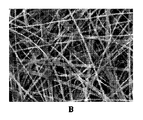
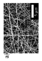
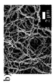
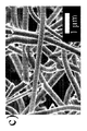
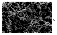
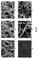
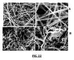
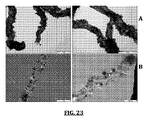
図4および図9は、明細書に記載されたガスアシスト法(例えば、同軸にガスアシスト)を用いてポリマーおよびナノ粒子を含有する流体ストックを電界紡糸することにより製造したナノファイバーを示す。図5は、本明細書に記載したガスアシスト工程を用いないポリマーおよびナノ粒子を含む流体ストックを電界紡糸することにより製造した特定のナノファイバーを示す図である。図4および図9はマトリックス/骨格材料内のナノ粒子の非凝集を示しているのに対して、図5は、マトリクス材料内のナノ粒子の凝集を示している。 4 and 9 show nanofibers made by electrospinning a fluid stock containing polymer and nanoparticles using the gas assist method described in the specification (eg, coaxially gas assist). FIG. 5 is a diagram illustrating certain nanofibers produced by electrospinning a fluid stock containing polymers and nanoparticles without the gas assist process described herein. 4 and 9 show the non-aggregation of nanoparticles within the matrix / framework material, while FIG. 5 shows the aggregation of nanoparticles within the matrix material.
いくつかの態様では、ケイ素材料ドメインは、非凝集である。特定の態様では、ナノファイバーは凝集しているドメイン(例えば、Siナノ粒子)を50%未満含む。特定の態様では、ナノファイバーは凝集しているドメイン(例えば、Siナノ粒子)を40%未満含む。特定の態様では、ナノファイバーは凝集しているドメイン(例えば、Siナノ粒子)を25%未満含む。特定の態様では、ナノファイバーは凝集しているドメイン(例えば、Siナノ粒子)を10%未満含む。特定の態様では、ナノファイバーは凝集しているドメイン(例えば、Siナノ粒子)を5%未満含む。 In some embodiments, the silicon material domain is non-aggregated. In certain embodiments, the nanofiber comprises less than 50% aggregated domains (eg, Si nanoparticles). In certain embodiments, the nanofiber comprises less than 40% aggregated domains (eg, Si nanoparticles). In certain embodiments, the nanofiber comprises less than 25% aggregated domains (eg, Si nanoparticles). In certain embodiments, the nanofiber comprises less than 10% aggregated domains (eg, Si nanoparticles). In certain embodiments, the nanofiber comprises less than 5% aggregated domains (eg, Si nanoparticles).
特定の態様では、本発明に係るナノ複合ナノファイバーは、直接隣接したセグメントの10倍以上(20倍、30倍、50倍など)の濃度で一セグメント(例えば、500nm、1ミクロン、1.5ミクロン、2ミクロン)中にドメイン濃度を含まない。いくつかの態様では、このような測定のためのセグメント・サイズは、例えば、500ナノメートル、1ミクロン、1.5ミクロン、2ミクロンの長さである。他の態様では、セグメントサイズは、平均ドメイン(例えば、粒子)のサイズの関数である(例えば、セグメントは、平均ドメインサイズの5倍、10倍、20倍、100倍である)。いくつかの態様では、ドメインは、サイズが1〜1000nm、1nm〜500nm、1〜200nm、1〜100nmで、20〜30nmの、1nm〜20nm、30nm〜90nm、40nm〜70nm、15〜40nmなどの(平均)サイズを有する。 In certain embodiments, the nanocomposite nanofibers according to the present invention have one segment (eg, 500 nm, 1 micron, 1.5 micron, etc.) at a concentration of 10 times or more (20 times, 30 times, 50 times, etc.) of directly adjacent segments. 2 micron) does not contain domain concentration. In some embodiments, the segment size for such measurements is, for example, 500 nanometers, 1 micron, 1.5 microns, 2 microns long. In other embodiments, the segment size is a function of the size of the average domain (eg, particles) (eg, the segment is 5, 10, 20 or 100 times the average domain size). In some embodiments, the domain has a size of 1-1000 nm, 1 nm-500 nm, 1-200 nm, 1-100 nm, 20-30 nm, 1 nm-20 nm, 30 nm-90 nm, 40 nm-70 nm, 15-40 nm, etc. (Average) size.
いくつかの態様では、ナノ複合ナノファイバーは、
本明細書に記載されている不連続ドメイン(例えば、ナノ粒子)を含有する複数のセグメント(例えば、0.5ミクロン、1ミクロン、1.5ミクロン、2ミクロンなど)を含有し、複数のセグメントはその中において不連続ドメインの平均濃度を有する(すなわち、セグメント当たりのドメイン/粒子)。
特定の態様では、複数のセグメントの大半は、平均80%以内の不連続ドメイン濃度を有する。より具体的な態様では、複数のセグメントの大半は、平均60%以内の不連続ドメインの濃度を有する。さらにより具体的な態様では、複数のセグメントの大半は、平均50%以内の不連続ドメインの濃度を有する。さらにより具体的な態様では、複数のセグメントの大半は、平均40%以内の不連続ドメインの濃度を有する。より具体的な態様では、複数のセグメントの大半は、平均30%以内の不連続ドメインの濃度を有する。さらにより具体的な態様では、複数のセグメントの大半は、平均20%以内の不連続ドメインの濃度を有する。さらにより具体的な態様では、少なくとも30%、少なくとも50%、少なくとも60%、少なくとも70%、少なくとも80%、または90%以内の複数のセグメントは、平均90%、80%、 60%、50%、40%、30%または20%の不連続ドメインの濃度を有する。
In some embodiments, the nanocomposite nanofiber is
Contains a plurality of segments (eg, 0.5 microns, 1 micron, 1.5 microns, 2 microns, etc.) containing discontinuous domains (eg, nanoparticles) as described herein, wherein the plurality of segments are within It has an average concentration of discontinuous domains (ie domains / particles per segment).
In certain embodiments, the majority of the plurality of segments have an average discontinuous domain concentration within 80%. In a more specific aspect, the majority of the plurality of segments has a concentration of discrete domains within an average of 60%. In an even more specific embodiment, the majority of the plurality of segments has an average concentration of discontinuous domains within 50%. In an even more specific embodiment, the majority of the plurality of segments has a concentration of discrete domains within an average of 40%. In a more specific embodiment, the majority of the plurality of segments has a concentration of discrete domains within an average of 30%. In an even more specific embodiment, the majority of the plurality of segments have a concentration of discrete domains within an average of 20%. In an even more specific aspect, a plurality of segments within at least 30%, at least 50%, at least 60%, at least 70%, at least 80%, or 90% average 90%, 80%, 60%, 50% Having a concentration of 40%, 30% or 20% discontinuous domains.
ケイ素材料
さまざまな態様において、本発明に係るナノ複合ナノファイバー中のケイ素材料は、任意の適切なケイ素材料である。いくつかの態様において、ケイ素材料は、ケイ素、ケイ素合金(例えば、ケイ素金属酸化物)、又はケイ素前駆体である。特定の態様において、ケイ素材料は、リチウムイオン電池の陽極又は負極に使用するのに適した材料である。いくつかの態様において、ケイ素材料は、リチウムイオン電池の陽極又は負極に使用するのに適した材料に変換され得る材料の前駆体である。さまざまな態様において、ケイ素材料のケイ素が結晶状態である。さまざまな態様において、ケイ素材料のケイ素は、ゼロ酸化状態、正の酸化状態、又はこれらの組み合わせである。特定の態様において、ケイ素材料のケイ素は、一般的にゼロ酸化状態である(例えば、+0酸化状態、または平均+0.05未満の酸化状態を有する)。
Silicon Material In various embodiments, the silicon material in the nanocomposite nanofiber according to the present invention is any suitable silicon material. In some embodiments, the silicon material is silicon, a silicon alloy (eg, silicon metal oxide), or a silicon precursor. In certain embodiments, the silicon material is a material suitable for use in the anode or negative electrode of a lithium ion battery. In some embodiments, the silicon material is a precursor of a material that can be converted to a material suitable for use in the anode or negative electrode of a lithium ion battery. In various embodiments, the silicon of the silicon material is in a crystalline state. In various embodiments, the silicon of the silicon material is in a zero oxidation state, a positive oxidation state, or a combination thereof. In certain embodiments, the silicon of the silicon material is generally in a zero oxidation state (eg, having a +0 oxidation state, or an average less than +0.05 oxidation state).
具体的な態様では、本発明に係るナノ複合ナノファイバーは、ケイ素ナノ粒子を含む。特定の態様では、ケイ素ナノ粒子は、少なくとも90重量%のゼロ酸化ケイ素および10重量%未満の二酸化ケイ素を含有する。より具体的な態様では、ケイ素ナノ粒子は、少なくとも95重量%のゼロ酸化ケイ素および5重量%未満の二酸化ケイ素を含有する。さらにより具体的な態様では、ケイ素ナノ粒子は、90〜99重量%のゼロ酸化ケイ素および0.01(または0.1)〜5重量%の二酸化ケイ素を含有する。 In a specific embodiment, the nanocomposite nanofiber according to the present invention comprises silicon nanoparticles. In certain embodiments, the silicon nanoparticles contain at least 90% by weight silicon zero oxide and less than 10% by weight silicon dioxide. In a more specific embodiment, the silicon nanoparticles contain at least 95% by weight silicon zero oxide and less than 5% by weight silicon dioxide. In an even more specific embodiment, the silicon nanoparticles contain 90-99 wt% silicon zero oxide and 0.01 (or 0.1) -5 wt% silicon dioxide.
特定の態様では、不連続ケイ素材料ドメイン(例えば、ケイ素ナノ粒子)は、200nm未満の平均直径を有する。特定の態様において、平均直径は1nm〜200nmである。いくつかの態様では、平均直径は100nm未満である。特定の態様において、平均直径は10nm〜100nmである。より具体的な態様において、平均直径は10nm〜80nmである。さらにより特定の態様において、平均直径は、20nm〜70nmである。 In certain embodiments, the discontinuous silicon material domains (eg, silicon nanoparticles) have an average diameter of less than 200 nm. In certain embodiments, the average diameter is 1 nm to 200 nm. In some embodiments, the average diameter is less than 100 nm. In certain embodiments, the average diameter is between 10 nm and 100 nm. In a more specific embodiment, the average diameter is 10 nm to 80 nm. In an even more specific embodiment, the average diameter is 20 nm to 70 nm.
本発明に係る特定の態様では、ケイ素材料を含むナノ複合ナノファイバーが提供され、ケイ素材料はケイ素(および他の任意の成分)を含有する。特定の態様において、ナノ複合ナノファイバーは、(例えば、複数のナノファイバーの平均において)少なくとも25重量%のケイ素材料を含有する。より具体的な態様において、ナノ複合ナノファイバーは、(例えば、複数のナノファイバーの平均において)少なくとも50重量%のケイ素材料を含有する。さらにより特定の態様において、ナノ複合ナノファイバーは、(例えば、複数のナノファイバーの平均において)少なくとも60重量%のケイ素材料を含有する。さらにより具体的な態様において、ナノ複合ナノファイバーは、(例えば、複数のナノファイバーの平均において)少なくとも70重量%のケイ素材料を含有する。特定の態様において、ナノ複合ナノファイバーは、(例えば、複数のナノファイバーの平均において)少なくとも80重量%のケイ素材料を含有する。 In a particular embodiment according to the present invention, a nanocomposite nanofiber comprising a silicon material is provided, the silicon material containing silicon (and other optional components). In certain embodiments, the nanocomposite nanofiber contains at least 25% by weight silicon material (eg, on an average of the plurality of nanofibers). In a more specific embodiment, the nanocomposite nanofiber contains at least 50% by weight silicon material (eg, on an average of the plurality of nanofibers). In an even more specific embodiment, the nanocomposite nanofiber contains at least 60 wt% silicon material (eg, on an average of the plurality of nanofibers). In an even more specific embodiment, the nanocomposite nanofiber contains at least 70% by weight silicon material (eg, on average of the plurality of nanofibers). In certain embodiments, the nanocomposite nanofiber contains at least 80% by weight silicon material (eg, on an average of the plurality of nanofibers).
特定の態様では、ナノ複合ナノファイバーは、少なくとも25重量%のケイ素を含有する(例えば、成分基準であり、複数のナノファイバーの平均である)。特定の態様において、ナノ複合ナノファイバーは、少なくとも50重量%のケイ素を含有する(例えば、成分基準であり、複数のナノファイバーの平均である)。より具体的な態様において、ナノ複合ナノファイバーは、少なくとも75重量%のケイ素を含有する(例えば、成分基準であり、複数のナノファイバーの平均である)。さらにより具体的な態様において、ナノ複合ナノファイバーは、少なくとも90重量%のケイ素を含有する(例えば、成分基準であり、複数のナノファイバーの平均である)。特定の態様において、ナノ複合ナノファイバーは、少なくとも95重量%のケイ素を含有する(例えば、成分基準であり、複数のナノファイバーの平均である)。 In certain embodiments, the nanocomposite nanofibers contain at least 25% by weight silicon (eg, on a component basis and an average of a plurality of nanofibers). In certain embodiments, the nanocomposite nanofiber contains at least 50% by weight silicon (eg, on a component basis and an average of a plurality of nanofibers). In a more specific embodiment, the nanocomposite nanofiber contains at least 75% silicon by weight (eg, on a component basis and an average of a plurality of nanofibers). In an even more specific embodiment, the nanocomposite nanofiber contains at least 90% by weight silicon (eg, on a component basis and an average of a plurality of nanofibers). In certain embodiments, the nanocomposite nanofiber contains at least 95% silicon by weight (eg, on a component basis and an average of a plurality of nanofibers).
いくつかの態様において、ケイ素材料は、ケイ素、ケイ素酸化物、ケイ素カーバイド、またはそれらの組み合わせを含む。特定の態様において、ケイ素材料は、ケイ素を含む。いくつかの態様では、ケイ素材料のケイ素は、実質的にゼロ酸化状態である。特定の態様において、少なくとも50%、少なくとも60%、少なくとも70%、少なくとも80%、少なくとも90%、少なくとも95%などのケイ素材料中のケイ素は中性(ゼロ)酸化状態である。 In some embodiments, the silicon material comprises silicon, silicon oxide, silicon carbide, or combinations thereof. In certain embodiments, the silicon material comprises silicon. In some embodiments, the silicon of the silicon material is in a substantially zero oxidation state. In certain embodiments, the silicon in the silicon material, such as at least 50%, at least 60%, at least 70%, at least 80%, at least 90%, at least 95%, etc. is in a neutral (zero) oxidation state.
特定の態様では、ケイ素材料は、以下の式(I)により表される1種以上の材料を含有するか、この式で表されるものである: In a particular embodiment, the silicon material contains or is represented by one or more materials represented by the following formula (I):
![]()
![]()
いくつかの態様では、Mは1種以上の金属(例えば、Mn, Mo, Nb, W, Ta, Fe, Cu, Ti, V, Cr, Ni, Co, Zr, Y、またはそれらの組み合わせ)である。特定の態様では、(q+x)>2y+z; q≧0, および z≧0である。いくつかの態様において、q、x、y及びzは原子パーセント値を表している。より具体的な態様において、q、xおよびyは、それぞれ0以上である。 In some embodiments, M is one or more metals (eg, Mn, Mo, Nb, W, Ta, Fe, Cu, Ti, V, Cr, Ni, Co, Zr, Y, or combinations thereof). is there. In certain embodiments, (q + x)> 2y + z; q ≧ 0, and z ≧ 0. In some embodiments, q, x, y and z represent atomic percent values. In a more specific embodiment, q, x and y are each 0 or more.
第二の材料
いくつかの態様では、本発明に係るナノ複合ナノファイバーは、ケイ素材料と第二材料を含有する。特定の態様において、追加材料は、必要に応じて存在する。本発明に記載のいくつかの態様では、第二材料は、本明細書に記載される連続的なマトリックス材料である。本発明において、第二材料は、本明細書に記載される第二ケイ素材料、例えば、ケイ素およびシリカである。いくつかの態様では、第二の材料はポリマーである(例えば、水溶性有機ポリマーなどの有機ポリマーである)。他の態様では、第二材料は、金属酸化物、セラミック、金属(例えば、単一の金属材料または合金)、炭素等である。いくつかの態様では、第二材料は、少なくとも3%、少なくとも5%、少なくとも10%、少なくとも15%、少なくとも20%、少なくとも30%などの第二の材料(例えば、炭素)を含有する。
Second Material In some embodiments, the nanocomposite nanofiber according to the present invention comprises a silicon material and a second material. In certain embodiments, additional material is optionally present. In some embodiments described in the present invention, the second material is a continuous matrix material as described herein. In the present invention, the second material is a second silicon material described herein, such as silicon and silica. In some embodiments, the second material is a polymer (eg, an organic polymer such as a water soluble organic polymer). In other embodiments, the second material is a metal oxide, ceramic, metal (eg, a single metal material or alloy), carbon, and the like. In some embodiments, the second material contains at least 3%, at least 5%, at least 10%, at least 15%, at least 20%, at least 30%, etc. of the second material (eg, carbon).
ナノファイバー
特定の態様では、本発明に係るナノ複合ナノファイバーは、任意の適切な特性を有している。
In a nanofiber specific embodiment, the nanocomposite nanofiber according to the present invention has any suitable properties.
いくつかの態様では、本発明に係るナノ複合ナノファイバーは、2ミクロン未満の直径(例えば、複数のナノファイバーの平均直径)を有する。特定の態様において、本発明に係るナノ複合ナノファイバーは、1.5ミクロン未満の直径(例えば、複数のナノファイバーの平均直径)を有する。より具体的な態様において、本発明に係るナノ複合ナノファイバーは、1ミクロン未満の直径(例えば、複数のナノファイバーの平均直径)を有する。さらにより特定の態様において、本発明に係るナノ複合ナノファイバーは、750nm未満の直径(例えば、複数のナノファイバーの平均直径)を有する。さらにより具体的な態様において、本発明に係るナノ複合ナノファイバーは、500nm未満の直径(例えば、複数のナノファイバーの平均直径)を有する。より具体的な態様において、本発明に係るナノ複合ナノファイバーは、250nm未満の直径(例えば、複数のナノファイバーの平均直径)を有する。 In some embodiments, nanocomposite nanofibers according to the present invention have a diameter of less than 2 microns (eg, an average diameter of a plurality of nanofibers). In certain embodiments, nanocomposite nanofibers according to the present invention have a diameter of less than 1.5 microns (eg, an average diameter of a plurality of nanofibers). In a more specific aspect, the nanocomposite nanofiber according to the present invention has a diameter of less than 1 micron (eg, the average diameter of a plurality of nanofibers). In an even more specific aspect, the nanocomposite nanofiber according to the present invention has a diameter of less than 750 nm (eg, an average diameter of a plurality of nanofibers). In an even more specific aspect, the nanocomposite nanofiber according to the present invention has a diameter of less than 500 nm (eg, an average diameter of a plurality of nanofibers). In a more specific embodiment, the nanocomposite nanofiber according to the present invention has a diameter of less than 250 nm (eg, an average diameter of a plurality of nanofibers).
いくつかの態様では、本発明に係るナノ複合ナノファイバーは、平均して少なくとも1μm、少なくとも10μm、少なくとも20μm、少なくとも100μm、少なくとも500μm、少なくとも1000μm、少なくとも5000μm、少なくとも10000μmなどの長さを有する。 In some embodiments, nanocomposite nanofibers according to the present invention have an average length of at least 1 μm, at least 10 μm, at least 20 μm, at least 100 μm, at least 500 μm, at least 1000 μm, at least 5000 μm, at least 10,000 μm, and the like.
いくつかの態様では、本発明に係るナノ複合ナノファイバーは、10より大きいアスペクト比を有する(例えば、複数のナノファイバーの平均アスペクト比)。
特定の態様において、本発明で提供されるナノ複合ナノファイバーは、100より大きいアスペクト比を有する(例えば、複数のナノファイバーの平均アスペクト比)。より具体的な態様において、本発明で提供されるナノ複合ナノファイバーは、500より大きいアスペクト比を有する(例えば、複数のナノファイバーの平均アスペクト比)。さらにより具体的な態様では、本発明で提供されるナノ複合ナノファイバーは、1000より大きいアスペクト比を有する(例えば、複数のナノファイバーの平均アスペクト比)。
In some embodiments, a nanocomposite nanofiber according to the present invention has an aspect ratio greater than 10 (eg, an average aspect ratio of a plurality of nanofibers).
In certain embodiments, the nanocomposite nanofibers provided in the present invention have an aspect ratio greater than 100 (eg, an average aspect ratio of a plurality of nanofibers). In more specific embodiments, the nanocomposite nanofibers provided in the present invention have an aspect ratio greater than 500 (eg, an average aspect ratio of a plurality of nanofibers). In an even more specific aspect, the nanocomposite nanofiber provided in the present invention has an aspect ratio greater than 1000 (eg, an average aspect ratio of a plurality of nanofibers).
いくつかの態様では、ナノ複合ナノファイバーは架橋される。特定の例において、本発明において提供されるナノ複合ファイバーの第二材料(例えば、ケイ素不含第二材料)は、1つまたはそれ以上の隣接ナノファイバーの第二の材料と架橋される。 In some embodiments, the nanocomposite nanofiber is crosslinked. In certain instances, a second nanocomposite fiber material (eg, silicon-free second material) provided in the present invention is cross-linked with a second material of one or more adjacent nanofibers.
いくつかの態様において、本発明で提供されるナノファイバーは、併用される場合、(例えば、平均して)少なくとも99%、少なくとも98%、少なくとも97%、少なくとも96%、少なくとも95%、少なくとも90%、少なくとも80質量%(例えば元素重量)%などの金属、酸素、炭素を含有する。
いくつかの態様において、本発明で提供されるナノファイバーは、併用される場合、(例えば、平均して)少なくとも99%、少なくとも98%、少なくとも97%、少なくとも96%、少なくとも95%、少なくとも90%、少なくとも80質量%(例えば元素重量)%などの金属および酸素を含有する。
いくつかの態様において、本発明で提供されるナノファイバーは、併用される場合、(例えば、平均して)少なくとも99%、少なくとも98%、少なくとも97%、少なくとも96%、少なくとも95%、少なくとも90%、少なくとも80質量%(例えば元素重量)%などのケイ素、酸素および炭素を含有する。
いくつかの態様において、本発明で提供されるナノファイバーは、併用される場合、(例えば、平均して)少なくとも99%、少なくとも98%、少なくとも97%、少なくとも96%、少なくとも95%、少なくとも90%、少なくとも80質量%(例えば元素重量)%などのケイ素および炭素を含有する。
In some embodiments, the nanofibers provided by the present invention, when used in combination, are (eg, on average) at least 99%, at least 98%, at least 97%, at least 96%, at least 95%, at least 90%. %, Containing at least 80% by mass (for example, elemental weight)% of metal, oxygen, carbon.
In some embodiments, the nanofibers provided by the present invention, when used in combination, are (eg, on average) at least 99%, at least 98%, at least 97%, at least 96%, at least 95%, at least 90%. %, At least 80% by weight (eg elemental weight)% of the metal and oxygen.
In some embodiments, the nanofibers provided by the present invention, when used in combination, are (eg, on average) at least 99%, at least 98%, at least 97%, at least 96%, at least 95%, at least 90%. %, At least 80% by mass (eg elemental weight)% of silicon, oxygen and carbon.
In some embodiments, the nanofibers provided by the present invention, when used in combination, are (eg, on average) at least 99%, at least 98%, at least 97%, at least 96%, at least 95%, at least 90%. %, At least 80% by weight (eg elemental weight)% of silicon and carbon.
特定の態様において、骨格(例えば、連続芯マトリックスなどの連続マトリックス材料)を含むナノ複合ナノファイバーが提供され、骨格はそこに組み込まれたナノ粒子を含有し、骨格は炭素およびケイ素含有ナノ粒子を含有する。より具体的な態様では、ナノファイバーは、図6中に記載したものと同一または類似のX線回折(XRD)パターンを有する。いくつかの態様では、ナノファイバーは、図6に示されたXRDパターンにおけるピークの少なくとも3つを有するXRDパターンを示す。
いくつかの態様では、ナノファイバーは、図6に示されたXRDパターンにおけるピークの少なくとも4つを有するXRDパターンを示す。
いくつかの態様では、ナノファイバーは、図6に示されたXRDパターンにおけるピークの少なくとも5つを有するXRDパターンを示す。
いくつかの態様では、ナノファイバーは、28.37°±0.03、47.20°±0.03、56.09°±0.03、69.02°±0.03および76.37°±0.03のピークの少なくとも3つを有するXRDパターンを示す。
いくつかの態様では、ナノファイバーは、28.37°±0.03、47.20°±0.03、56.09°±0.03、69.02°±0.03および76.37°±0.03のピークの少なくとも4つを有するXRDパターンを示す。
いくつかの態様では、ナノファイバーは、28.37°±0.03、47.20°±0.03、56.09°±0.03、69.02°±0.03および76.37°±0.03のピークの少なくとも5つを有するXRDパターンを示す。
In certain embodiments, nanocomposite nanofibers comprising a scaffold (eg, a continuous matrix material such as a continuous core matrix) are provided, the scaffold contains nanoparticles incorporated therein, and the scaffold contains carbon and silicon-containing nanoparticles. contains. In a more specific embodiment, the nanofiber has an X-ray diffraction (XRD) pattern that is the same or similar to that described in FIG. In some embodiments, the nanofiber exhibits an XRD pattern having at least three of the peaks in the XRD pattern shown in FIG.
In some embodiments, the nanofiber exhibits an XRD pattern having at least four of the peaks in the XRD pattern shown in FIG.
In some embodiments, the nanofiber exhibits an XRD pattern having at least five of the peaks in the XRD pattern shown in FIG.
In some embodiments, the nanofibers are 28.37 ° ± 0.03, 47.20 ° ± 0.03, 56.09 ° ± 0.03, 69.02 ° ± 0.03 and 76.37 °. An XRD pattern with at least three of the ± 0.03 peaks is shown.
In some embodiments, the nanofibers are 28.37 ° ± 0.03, 47.20 ° ± 0.03, 56.09 ° ± 0.03, 69.02 ° ± 0.03 and 76.37 °. An XRD pattern with at least four of the ± 0.03 peaks is shown.
In some embodiments, the nanofibers are 28.37 ° ± 0.03, 47.20 ° ± 0.03, 56.09 ° ± 0.03, 69.02 ° ± 0.03 and 76.37 °. An XRD pattern with at least five of the ± 0.03 peaks is shown.
いくつかの態様において、(1つまたは複数の本発明に記載のナノファイバーを含む)ナノファイバーマットの空隙率は、少なくとも5%、少なくとも10%、少なくとも15%、少なくとも20%、少なくとも25%、または50%等である。
空隙率は、任意の適切な方法で測定することができる。
例えば、いくつかの例において、ナノファイバーマットの空隙率は、ナノファイバーマットを流体で満たすか流体に沈めた後、にナノファイバーマット内のに存在する流体の体積を測定することによって測定される。
In some embodiments, the porosity of the nanofiber mat (including one or more nanofibers according to the present invention) is at least 5%, at least 10%, at least 15%, at least 20%, at least 25%, Or 50%.
The porosity can be measured by any appropriate method.
For example, in some examples, the porosity of a nanofiber mat is measured by measuring the volume of fluid present within the nanofiber mat after the nanofiber mat is filled or submerged with fluid. .
ここに記載されるのは、複数の孔を持つナノファイバーと複数の孔を持つナノファイバーの製造方法である。細孔は、任意の適切なサイズまたは形状であってもよい。いくつかの態様では、細孔は、100nm未満の直径を有する(例えば、平均して、2〜50nmの間に直径を有する)「メソ細孔」である。いくつかの態様では、細孔は、実質的に均一な形状、実質的に均一なサイズを有しおよび/またはナノファイバー介して実質的に均一に分散しているように「規則的である」。いくつかの態様において、本発明に記載のナノファイバーは、高い表面積および/または比表面積(例えば、ナノファイバーの質量当たりの表面積および/またはナノファイバーの体積あたり表面積)を有する。いくつかの態様では、本発明に係るナノファイバーは、秩序的な孔を有し、実質的に可撓性および/または非脆性である。 Described herein is a method for producing nanofibers having a plurality of pores and nanofibers having a plurality of pores. The pores may be any suitable size or shape. In some embodiments, the pores are “mesopores” having a diameter of less than 100 nm (eg, having a diameter between 2 and 50 nm on average). In some embodiments, the pores are “regular” such that they have a substantially uniform shape, a substantially uniform size, and / or are substantially uniformly distributed through the nanofibers. . In some embodiments, the nanofibers described in the present invention have a high surface area and / or specific surface area (eg, surface area per mass of nanofiber and / or surface area per volume of nanofiber). In some embodiments, nanofibers according to the present invention have ordered pores and are substantially flexible and / or non-brittle.
一態様において、本発明に係るナノファイバーは、(a)少なくとも10πrhの表面積(rはナノファイバーの半径であり、hは、ナノファイバーの長さである);(b)少なくとも10m2/g比表面積(例えば、少なくとも100m2/g比表面積);(c)少なくとも20%の空隙率と少なくとも1μmの長さ;(d)少なくとも35%の空隙率、ナノファイバーは実質的に連続している;(e)少なくとも35%の空隙率、ナノファイバーは、実質的に可撓性または非脆性である;(f)少なくとも1nm以上の平均直径を有する複数の細孔;(g)実質的に均一な形状を有することを特徴とする複数の細孔;(h)実質的に均一なサイズを有することを特徴とする複数の細孔;(i)およびナノファイバー全体に実質的に均一に分散している細孔を有することの1つ以上のことを含む。 In one embodiment, the nanofiber according to the present invention comprises (a) a surface area of at least 10πrh (where r is the radius of the nanofiber and h is the length of the nanofiber); (b) a ratio of at least 10 m 2 / g Surface area (eg, at least 100 m 2 / g specific surface area); (c) a porosity of at least 20% and a length of at least 1 μm; (d) a porosity of at least 35%; the nanofibers are substantially continuous; (E) a porosity of at least 35%, the nanofibers are substantially flexible or non-brittle; (f) a plurality of pores having an average diameter of at least 1 nm or more; (g) substantially uniform A plurality of pores characterized by having a shape; (h) a plurality of pores characterized by having a substantially uniform size; (i) and substantially uniformly dispersed throughout the nanofiber Including one or more that of having that pores.
いくつかの態様では、細孔は、球、円柱、レイヤー、チャンネル、またはそれらの任意の組合せを含む。いくつかの態様では、細孔は、らせん状である。いくつかの態様において、ナノファイバーは、金属、金属合金、セラミック、ポリマー、またはそれらの任意の組合せを含む。 In some embodiments, the pore comprises a sphere, cylinder, layer, channel, or any combination thereof. In some embodiments, the pores are helical. In some embodiments, the nanofiber comprises a metal, metal alloy, ceramic, polymer, or any combination thereof.
一態様において、規則性のメソ多孔性ナノファイバーを製造する方法が提供され、この方法は以下の工程を含む:
(a)第一流体ストックと第二流体ストックを同軸上に電界紡糸し、第一ナノ繊維を製造する工程、第一流体ストックは少なくとも1種のブロックコポリマーとケイ素成分(例えば、シリコン前駆体)を含有し、第二流体ストックはコーティング剤を含有し、第一ナノファイバーは第一層(例えば芯)、第1層を少なくとも部分的に被覆する第二層(例えば、コーティング);
(b)第一ナノファイバーをアニールする工程;(c)第一ナノ繊維から第二層を所望により除去し、ブロックコポリマーを含む第二ナノ繊維を生成する工程;(d)第一ナノファイバーまたは第二ナノファイバーからブロックコポリマーの少なくとも一部を選択的に除去する工程(例えば、それによって、規則性メソ多孔質ナノファイバーが製造される)。
追加の同軸層は任意であり、例えば、更なるメソ多孔質層用の前駆体とブロック共重合体を含有し、または非メソ多孔質用の本明細書に記載されている前駆体およびポリマーを含有する。
In one aspect, a method for producing ordered mesoporous nanofibers is provided, the method comprising the following steps:
(A) electrospinning the first fluid stock and the second fluid stock coaxially to produce a first nanofiber, wherein the first fluid stock comprises at least one block copolymer and a silicon component (eg, silicon precursor) The second fluid stock contains a coating agent, the first nanofibers are a first layer (eg, a core), a second layer (eg, a coating) that at least partially covers the first layer;
(B) annealing the first nanofiber; (c) optionally removing the second layer from the first nanofiber to produce a second nanofiber comprising a block copolymer; (d) the first nanofiber or Selectively removing at least a portion of the block copolymer from the second nanofiber (eg, thereby producing ordered mesoporous nanofibers).
The additional coaxial layer is optional, for example, containing precursors and block copolymers for additional mesoporous layers, or precursors and polymers described herein for non-mesoporous. contains.
いくつかの態様において、ブロックコポリマーは、ポリイソプレン(PI)ブロック、ポリ乳酸(PLA)ブロック、ポリビニルアルコール(PVA)ブロック、ポリエチレンオキシド(PEO)ブロック、ポリビニルピロリドン(PVP)ブロック、ポリアクリルアミド(PAA)ブロックまたはその任意の組み合わせを含む(すなわち、熱的にまたは化学的に分解性ポリマーである)。
いくつかの態様において、ブロックコポリマーは、ポリスチレン(PS)ブロック、ポリ(メチルメタクリレート)(PMMA)ブロック、ポリアクリロニトリル(PAN)ブロック、またはそれらの任意の組合せを含む。
In some embodiments, the block copolymer is a polyisoprene (PI) block, a polylactic acid (PLA) block, a polyvinyl alcohol (PVA) block, a polyethylene oxide (PEO) block, a polyvinylpyrrolidone (PVP) block, a polyacrylamide (PAA). Including a block or any combination thereof (ie, a thermally or chemically degradable polymer).
In some embodiments, the block copolymer comprises a polystyrene (PS) block, a poly (methyl methacrylate) (PMMA) block, a polyacrylonitrile (PAN) block, or any combination thereof.
いくつかの態様では、コーティング層とのブロック共重合体の少なくとも一部は(同時にまたは連続して)、加熱などによって、オゾン分解によって、酸で処理することにより、塩基で処理することにより、水で処理することにより、軟質および硬質(CASH)化学的性質またはそれらの任意の組み合わせなどの任意の適切な方法で選択的に除去される。さらに、米国特許出願第61/599541および国際出願PCT/US 13/26060(2013年2月14日出願)は、このような技術に関連する開示のために参照により本発明に組み込まれる。 In some embodiments, at least a portion of the block copolymer with the coating layer (simultaneously or sequentially) is treated with water, by treatment with an acid, by ozonolysis, such as by heating, by ozonolysis. Is selectively removed in any suitable manner, such as soft and hard (CASH) chemistry or any combination thereof. In addition, US patent application 61/599541 and international application PCT / US 13/26060 (filed February 14, 2013) are hereby incorporated by reference into the present invention for disclosure relating to such technology.
バッテリおよび電極
本発明に係るいくつかの態様では、本発明に記載の少なくとも一つのナノファイバーを備えた電池(例えば、一次または二次電池)が提供される。特定の例において、電池は、複数のナノファイバー、例えば、それらの不織マットを含有する。いくつかの態様では、バッテリは、少なくとも2つの電極(例えば、陽極及び陰極)とセパレータを含み、少なくとも一方の電極は、本発明に記載の少なくとも一つのナノファイバーを含む。特定の態様では、電池はリチウムイオン電池であり、陽極は、本発明に記載の少なくとも1つのナノファイバーを含み、例えば、そのナノファイバーマットが挙げられる。同様に、本発明に記載の任意のナノ複合ナノファイバーを含む電極が提供される(例えば、ナノファイバーマットは、1つ以上のそのようなナノファイバーを含む)。
Battery and Electrode In some embodiments according to the present invention, a battery (eg, a primary or secondary battery) comprising at least one nanofiber according to the present invention is provided. In certain instances, the battery contains a plurality of nanofibers, such as their nonwoven mats. In some embodiments, the battery includes at least two electrodes (eg, an anode and a cathode) and a separator, and at least one electrode includes at least one nanofiber according to the present invention. In a particular embodiment, the battery is a lithium ion battery and the anode comprises at least one nanofiber according to the present invention, for example its nanofiber mat. Similarly, an electrode is provided that includes any nanocomposite nanofiber described in the present invention (eg, a nanofiber mat includes one or more such nanofibers).
いくつかの態様では、電池は、本発明に記載のナノ複合ナノファイバーを複数備えた負極(陽極)を含む。
特定の態様では、負極またはナノ複合ナノファイバーは、0.1Cでの第1サイクルにおいて少なくとも1500mAh/gの比エネルギー容量または放電容量を有する(例えば、半電池または全電池試験によって決定される)。
さらなるまたは代替の態様では、負極またはナノ複合ナノファイバーは、0.1Cでの第1サイクルにおいて少なくとも2000mAh/gの比エネルギー容量または放電容量を有する
さらなるまたは代替の態様では、負極またはナノ複合ナノファイバーは、0.1Cでの第10サイクルにおいて少なくとも1400mAh/gの比エネルギー容量または放電容量を有する。
さらなるまたは代替の態様では、負極またはナノ複合ナノファイバーは、0.1Cでの第10サイクルにおいて少なくとも1800mAh/gの比エネルギー容量または放電容量を有する。
さらなるまたは代替の態様では、負極またはナノ複合ナノファイバーは、0.1Cでの第50サイクルにおいて少なくとも1000mAh/gの比エネルギー容量または放電容量を有する。
さらなるまたは代替の態様では、負極またはナノ複合ナノファイバーは、0.1Cでの第50サイクルにおいて少なくとも1600mAh/gの比エネルギー容量または放電容量を有する。
さらなるまたは代替の態様では、負極またはナノ複合ナノファイバーは、0.1Cでの第98サイクルにおいて少なくとも250mAh/gの比エネルギー容量または放電容量を有する。
さらなるまたは代替の態様では、負極またはナノ複合ナノファイバーは、0.1Cでの第98サイクルにおいて少なくとも400mAh/gの比エネルギー容量または放電容量を有する。
In some embodiments, the battery includes a negative electrode (anode) comprising a plurality of nanocomposite nanofibers described in the present invention.
In certain aspects, the negative electrode or nanocomposite nanofiber has a specific energy capacity or discharge capacity of at least 1500 mAh / g in the first cycle at 0.1 C (eg, as determined by half-cell or full-cell testing).
In further or alternative embodiments, the negative electrode or nanocomposite nanofiber has a specific energy capacity or discharge capacity of at least 2000 mAh / g in the first cycle at 0.1 C. In a further or alternative embodiment, the negative electrode or nanocomposite nanofiber Has a specific energy capacity or discharge capacity of at least 1400 mAh / g in the 10th cycle at 0.1 C.
In further or alternative embodiments, the negative electrode or nanocomposite nanofiber has a specific energy capacity or discharge capacity of at least 1800 mAh / g in the 10th cycle at 0.1 C.
In further or alternative embodiments, the negative electrode or nanocomposite nanofiber has a specific energy capacity or discharge capacity of at least 1000 mAh / g in the 50th cycle at 0.1 C.
In further or alternative embodiments, the negative electrode or nanocomposite nanofiber has a specific energy capacity or discharge capacity of at least 1600 mAh / g in the 50th cycle at 0.1 C.
In further or alternative embodiments, the negative electrode or nanocomposite nanofiber has a specific energy capacity or discharge capacity of at least 250 mAh / g in the 98th cycle at 0.1 C.
In further or alternative embodiments, the negative electrode or nanocomposite nanofiber has a specific energy capacity or discharge capacity of at least 400 mAh / g in the 98th cycle at 0.1 C.
本発明に係る特定の態様では、ケイ素(例えば、ケイ素ナノ粒子)含有負極または複数のナノ複合ナノファイバーは、0.1Cで第1サイクルにおける比エネルギー容量または放電容量の少なくとも40%の、0.1Cで第25サイクルにおける比エネルギー容量または放電容量を有する。
さらなる又は代替的な態様において、ケイ素(例えば、ケイ素ナノ粒子)含有負極または複数のナノ複合ナノファイバーは、0.1Cで第1サイクルにおける比エネルギー容量または放電容量の少なくとも50%の、0.1Cで第25サイクルにおける比エネルギー容量または放電容量を有する。特定の態様において、ケイ素(例えば、ケイ素ナノ粒子)含有負極または複数のナノ複合ナノファイバーは、0.1Cで第1サイクルにおける比エネルギー容量または放電容量の少なくとも10%の、0.1Cで第98サイクルにおける比エネルギー容量または放電容量を有する。さらなる又は代替的な態様において、ケイ素含有負極または複数のナノ複合ナノファイバーは、0.1Cで第1サイクルにおける比エネルギー容量または放電容量の少なくとも20%の、0.1Cで第98サイクルにおける比エネルギー容量または放電容量を有する。さらなる又は代替的な態様において、ケイ素(例えば、ケイ素ナノ粒子)含有負極または複数のナノ複合ナノファイバーは、0.1Cで第10サイクルにおける比エネルギー容量または放電容量の少なくとも20%の、0.1Cで第98サイクルにおける比エネルギー容量または放電容量を有する。さらなる又は代替的な態様において、ケイ素含有負極または複数のナノ複合ナノファイバーは、0.1Cで第10サイクルにおける比エネルギー容量または放電容量の少なくとも30%の、0.1Cで第98サイクルにおける比エネルギー容量または放電容量を有する。
In a particular embodiment according to the present invention, the silicon (eg silicon nanoparticle) -containing negative electrode or the plurality of nanocomposite nanofibers is 0.1 C, at least 40% of the specific energy capacity or discharge capacity in the first cycle, 0. 1C has specific energy capacity or discharge capacity in the 25th cycle.
In further or alternative embodiments, a silicon (eg, silicon nanoparticle) -containing negative electrode or a plurality of nanocomposite nanofibers is at 0.1C, at least 50% of the specific energy capacity or discharge capacity in the first cycle, And having a specific energy capacity or discharge capacity in the 25th cycle. In certain embodiments, a silicon (eg, silicon nanoparticle) -containing negative electrode or a plurality of nanocomposite nanofibers is at least 10% of the specific energy capacity or discharge capacity in the first cycle at 0.1C, and at 98C at 0.1C. It has a specific energy capacity or discharge capacity in the cycle. In further or alternative embodiments, the silicon-containing negative electrode or the plurality of nanocomposite nanofibers has a specific energy capacity at 0.1 C of at least 20% of the specific energy capacity or discharge capacity at the first cycle, at 0.1 C, at a specific energy at the 98th cycle. Have a capacity or discharge capacity. In further or alternative embodiments, a silicon (eg, silicon nanoparticle) -containing negative electrode or a plurality of nanocomposite nanofibers is at 0.1C, at least 20% of the specific energy capacity or discharge capacity at the 10th cycle at 0.1C. And having a specific energy capacity or discharge capacity in the 98th cycle. In further or alternative embodiments, the silicon-containing negative electrode or the plurality of nanocomposite nanofibers has a specific energy capacity at 0.1C of at least 30% of the specific energy capacity or discharge capacity at the 10th cycle, and a specific energy at the 98th cycle at 0.1C. Have a capacity or discharge capacity.
いくつかの態様において、本発明において提供される負極は、電流コレクタ上に高エネルギー(陽極)容量ナノファイバーを堆積させることによって製造され、これにより、電流コレクタと接触したナノファイバーを含有する負極が作成される。特定の態様では、処理されたままのナノファイバーを乳鉢及び乳棒を用いて粉砕して、加工ナノファイバーを製造し、その後、電流コレクタ上に堆積させる。いくつかの態様では、処理されたナノファイバー組成物を溶媒中に分散させて組成物を調製する。組成物を電流コレクタ上に堆積させ、溶媒を蒸発させることにより、電流コレクタ上に電極が形成される。特定の態様において、組成物はさらに結合剤を含む。さらなるまたは別の特定の態様において、電子移動度を向上させるために、組成物はさらに導電性材料、例えば、カーボンブラックを含有する。 In some embodiments, the negative electrodes provided in the present invention are manufactured by depositing high energy (anode) capacitive nanofibers on a current collector, whereby a negative electrode containing nanofibers in contact with the current collector is obtained. Created. In certain embodiments, as-processed nanofibers are ground using a mortar and pestle to produce processed nanofibers, which are then deposited on a current collector. In some embodiments, the treated nanofiber composition is dispersed in a solvent to prepare the composition. An electrode is formed on the current collector by depositing the composition on the current collector and evaporating the solvent. In certain embodiments, the composition further comprises a binder. In further or alternative specific embodiments, the composition further comprises a conductive material, such as carbon black, to improve electron mobility.
図7は、単独のSiナノ粒子と比較した本発明に係るSi / Cナノ複合ナノファイバーに関する、充電/放電曲線の第1サイクルおよび第25サイクル(パネルA)、およびクーロン効率のプロット曲線を示す(パネルB)。本発明で提供されるいくつかの態様では、Siナノ粒子を含有する負極または複数のナノ複合ナノファイバーは、図7に示されるものと少なくとも同じ大きさの容量を有する。本発明で提供されるいくつかの態様では、Siナノ粒子を含有する負極または複数のナノ複合ナノファイバーは、25サイクルにわたって少なくとも80%のクーロン効率を有する。本発明で提供されるいくつかの態様では、Siナノ粒子を含有する負極または複数のナノ複合ナノファイバーは、25サイクルにわたって少なくとも90%のクーロン効率を有する。 FIG. 7 shows the 1st and 25th cycles of the charge / discharge curve (panel A) and the coulomb efficiency plot for the Si / C nanocomposite nanofiber according to the present invention compared to a single Si nanoparticle. (Panel B). In some embodiments provided by the present invention, the negative electrode or the plurality of nanocomposite nanofibers containing Si nanoparticles have a capacity that is at least as large as that shown in FIG. In some embodiments provided herein, the negative electrode or nanocomposite nanofibers containing Si nanoparticles have a Coulomb efficiency of at least 80% over 25 cycles. In some embodiments provided in the present invention, the negative electrode or nanocomposite nanofibers containing Si nanoparticles have a Coulomb efficiency of at least 90% over 25 cycles.
図8は、様々な放電率における単独のケイ素ナノ粒子と比較した本発明に係る炭素ナノ複合ナノファイバー中のケイ素ナノ粒子の放電容量をプロットしたグラフである。
特定の態様において、本発明で提供されるナノ複合ナノファイバーは、任意のサイクル数または放電率にて、図8に示された値と少なくとも同じくらい大きい放電容量を有する。本発明で提供される特定の態様では、ナノ複合ナノファイバーは、0.1Cにて(例えば25サイクルの後)1450mAh/gの放電容量を有する。本発明で提供されるいくつかの態様において、ナノ複合ナノファイバーは、0.5Cにて(例えば25サイクルの後)1150mAh/gの放電容量を有する。本発明で提供されるいくつかの態様では、ナノ複合ナノファイバーは、0.8Cにて(例えば25サイクルの後)1000mAh/gの放電容量を有する。
FIG. 8 is a graph plotting the discharge capacity of silicon nanoparticles in carbon nanocomposite nanofibers according to the present invention compared to single silicon nanoparticles at various discharge rates.
In certain embodiments, the nanocomposite nanofibers provided by the present invention have a discharge capacity at least as large as the values shown in FIG. 8 at any number of cycles or discharge rates. In a particular embodiment provided in the present invention, the nanocomposite nanofiber has a discharge capacity of 1450 mAh / g at 0.1 C (eg after 25 cycles). In some embodiments provided by the present invention, the nanocomposite nanofiber has a discharge capacity of 1150 mAh / g at 0.5 C (eg after 25 cycles). In some embodiments provided in the present invention, the nanocomposite nanofiber has a discharge capacity of 1000 mAh / g at 0.8 C (eg after 25 cycles).
図10は、ケイ素ナノ粒子と、本発明に係るSi / Cナノ複合ナノファイバーのサイクリックボルタモグラム(パネルA)、およびナイキストプロット(パネルB)を示す図である。特定の態様では、本発明のナノ複合の電荷輸送抵抗(例えば、交流インピーダンスから決定される)は図10で示されている。いくつかの態様において、本発明に記載のナノ複合ナノファイバーの電荷輸送抵抗は100Ω未満である。特定の態様において、本発明に記載のナノ複合ナノファイバーの電荷輸送抵抗は75Ω未満である。より具体的な態様において、本発明に記載のナノ複合ナノファイバーの電荷輸送抵抗は65Ω未満である。特定の態様において、本発明に記載のナノ複合ナノファイバーの電荷輸送抵抗は60Ω未満である。さらなる又は代替的な態様において、本発明で提供されるナノ複合ナノファイバーの溶液(分極)抵抗は5Ω未満である(例えば、純粋なケイ素ナノ粒子の7.4Ωと比較される)。特定の態様において、本発明で提供されるナノ複合ナノファイバーの溶液(分極)抵抗は4Ω未満である。より具体的な態様において、本発明で提供されるナノ複合ナノファイバーの溶液(分極)抵抗は3.5Ω未満である。 FIG. 10 is a diagram showing a silicon nanoparticle, a cyclic voltammogram (panel A), and a Nyquist plot (panel B) of the Si / C nanocomposite nanofiber according to the present invention. In certain embodiments, the nanocomposite charge transport resistance (eg, determined from alternating current impedance) of the present invention is shown in FIG. In some embodiments, the charge transport resistance of the nanocomposite nanofibers described in the present invention is less than 100Ω. In certain embodiments, the charge transport resistance of the nanocomposite nanofibers described in the present invention is less than 75Ω. In a more specific embodiment, the charge transport resistance of the nanocomposite nanofiber according to the present invention is less than 65Ω. In certain embodiments, the charge transport resistance of the nanocomposite nanofibers described in the present invention is less than 60Ω. In further or alternative embodiments, the solution (polarization) resistance of the nanocomposite nanofibers provided by the present invention is less than 5Ω (eg, compared to 7.4Ω for pure silicon nanoparticles). In certain embodiments, the solution (polarization) resistance of the nanocomposite nanofibers provided by the present invention is less than 4Ω. In a more specific embodiment, the solution (polarization) resistance of the nanocomposite nanofiber provided in the present invention is less than 3.5Ω.
方法
本発明に係る特定の態様では、ケイ素含有ナノ複合ナノファイバーを製造する方法が提供される。(本発明中に記載されるように、例えば、)いくつかの態様では、このようなケイ素含有ナノ複合ナノファイバーはケイ素を多量に含んでいる。さらに、本発明で提供されるいくつかの態様において、高品質のナノファイバーおよび良好な構造的完全性、少数の空隙、構造欠陥の少ない、調整可能な長さ等を持つ高品質のナノファイバーの製造方法が提供される。
特定の態様では、流体ストックおよび/または前駆体/電界紡糸ナノファイバーにおけるポリマー荷重に比べて、前駆体または他のケイ素成分の高い荷重は、そのような高品質のナノファイバーを促進しおよび/または提供する。
Method In a particular aspect according to the present invention, a method for producing a silicon-containing nanocomposite nanofiber is provided. In some embodiments (eg, as described in the present invention), such silicon-containing nanocomposite nanofibers are rich in silicon. Further, in some embodiments provided by the present invention, high quality nanofibers and high quality nanofibers with good structural integrity, a small number of voids, fewer structural defects, adjustable lengths, etc. A manufacturing method is provided.
In certain embodiments, a high load of precursor or other silicon component compared to the polymer load in the fluid stock and / or precursor / electrospun nanofiber promotes such high quality nanofibers and / or provide.
いくつかの態様では、ケイ素材料とポリマーを含む電界紡糸ナノファイバーは、流体ストック電界紡糸することにより調製され、流体ストックは(1)ケイ素成分;および(2)ポリマーを含有する。特定の態様において、ケイ素成分は、ケイ素前駆体、ケイ素含有ナノ粒子(例えば、ケイ素、シリカ、式(I)のケイ素材料、またはそれらの任意の組み合わせを含むナノ粒子)を含む。より具体的な態様では、ケイ素成分は、ケイ素前駆体(例えば、ケイ素アセテート)である。他の特定の態様では、ケイ素成分はナノ粒子である。 In some embodiments, an electrospun nanofiber comprising a silicon material and a polymer is prepared by fluid stock electrospinning, wherein the fluid stock contains (1) a silicon component; and (2) a polymer. In certain embodiments, the silicon component comprises a silicon precursor, silicon-containing nanoparticles (eg, nanoparticles comprising silicon, silica, a silicon material of formula (I), or any combination thereof). In a more specific aspect, the silicon component is a silicon precursor (eg, silicon acetate). In another particular embodiment, the silicon component is a nanoparticle.
具体的な態様では、方法は、紡糸したままのナノ複合ナノファイバー(例えば、ポリマー、ケイ素成分(必要に応じてケイ素前駆体、前駆体はポリマー又は別の基またはリガンド/陰イオンと会合していてもよく、及び/又はケイ素含有ナノ粒子であってもよい)、及び、(同様に、ポリマーまたは他の基またはアニオンと会合していてもよい)金属前駆体を含有する)を更に処理することを含む。 In a specific embodiment, the method comprises as-spun nanocomposite nanofibers (eg, polymer, silicon component (optionally silicon precursor, precursor associated with polymer or another group or ligand / anion). And / or silicon-containing nanoparticles), and further containing metal precursors (which may also be associated with polymers or other groups or anions) Including that.
他の特定の態様では、ケイ素成分およびポリマーを含む電界紡糸ナノファイバーは、流体ストックを電界紡糸することにより調製され、流体ストックは、ケイ素含有ナノファイバーを含有する複数のナノ粒子;および(2)ポリマー(例えば、水溶性ポリマー)を含有する。 In another specific embodiment, an electrospun nanofiber comprising a silicon component and a polymer is prepared by electrospinning a fluid stock, wherein the fluid stock comprises a plurality of nanoparticles containing silicon-containing nanofibers; and (2) Contains a polymer (eg, a water soluble polymer).
特定の態様では、流体ストックは、水性媒体(、例えば、水/アルコール、水/酢酸などの水または水性混合物)を含む。 In certain embodiments, the fluid stock comprises an aqueous medium (eg, water or an aqueous mixture such as water / alcohol, water / acetic acid).
いくつかの態様において、処理工程は、(a)熱処理; (b)化学的処理を;または(c)それらの組み合わせを含む。 In some embodiments, the processing step comprises (a) heat treatment; (b) chemical treatment; or (c) combinations thereof.
特定の態様において、紡糸したままのナノ複合ナノファイバーの処理工程は、熱酸化条件下(例えば、空気の存在下)で、紡糸したままのナノ複合ナノファイバーを熱処理することを含む。他の特定の態様では、紡糸したままのナノ複合ナノファイバーの処理工程は、熱的に不活性な条件(例えば、アルゴン)の下で紡糸したままのナノ複合ナノファイバーを処理することを含む。さらに他の具体的な態様では、紡糸したままのナノ複合ナノファイバーの処理工程は、熱的還元条件(例えば、水素、または水素/アルゴン混合物)の下で紡糸したままのナノ複合ナノファイバーを処理することを含む。特定の態様では、紡糸されたままのナノファイバーは、約500℃から約2000℃、少なくとも900℃、少なくとも1000℃に加熱される。特定の態様において、紡糸されたままのナノファイバーは、約1000℃から約1800℃、または約1000℃から約1700℃に加熱される。特定の態様では、熱処理工程は、600℃〜1200℃で行われる。より具体的な態様では、熱処理工程は、700℃〜1000℃で行われる。さらにより具体的な態様では、熱処理工程は、(例えば、不活性または還元性雰囲気中で)800℃〜1000℃で行われる。 In certain embodiments, the processing step of the as-spun nanocomposite nanofiber comprises heat treating the as-spun nanocomposite nanofiber under thermal oxidation conditions (eg, in the presence of air). In another specific embodiment, the processing step of as-spun nanocomposite nanofibers includes processing as-spun nanocomposite nanofibers under thermally inert conditions (eg, argon). In yet another specific embodiment, the processing step of as-spun nanocomposite nanofibers treats as-spun nanocomposite nanofibers under thermal reduction conditions (eg, hydrogen or hydrogen / argon mixtures). Including doing. In certain embodiments, the as-spun nanofibers are heated to about 500 ° C. to about 2000 ° C., at least 900 ° C., at least 1000 ° C. In certain embodiments, the as-spun nanofibers are heated to about 1000 ° C. to about 1800 ° C., or about 1000 ° C. to about 1700 ° C. In a particular embodiment, the heat treatment step is performed at 600 ° C to 1200 ° C. In a more specific aspect, the heat treatment step is performed at 700 ° C to 1000 ° C. In an even more specific aspect, the heat treatment step is performed at 800 ° C. to 1000 ° C. (eg, in an inert or reducing atmosphere).
一態様では、工程は高い収率を有する(例えば、前駆体が高価である態様が望ましい)。
いくつかの態様では、ナノファイバー中の金属原子が、流体ストック中の金属(すなわちケイ素および他の金属)の数(例えば、モル単位)は約3%、約10%、約20%、約30%、約33%、約40%、約50%、約60%、約70%、約80%、約90%、約95%、約98%または約100%である。
In one aspect, the process has a high yield (eg, where the precursor is expensive is desirable).
In some embodiments, the metal atoms in the nanofibers have a number of metals (ie, silicon and other metals) in the fluid stock (ie, mole units) of about 3%, about 10%, about 20%, about 30 %, About 33%, about 40%, about 50%, about 60%, about 70%, about 80%, about 90%, about 95%, about 98% or about 100%.
いくつかの態様では、流体ストックは均一または均質である。
特定の態様において、記載された方法は、本発明の流体ストックの均一性または均質性を維持することを含む。いくつかの態様では、流体ストックの均一性および/または均一性は、撹拌、加熱等の任意の適切な機構によって達成されるか維持される。攪拌の方法は、非限定的な例として、混合、撹拌、振盪、超音波処理、または流体ストック中に複数の相が形成することを遅らせるか防ぐためのエネルギーの入力による他の方法が含まれる。
In some embodiments, the fluid stock is uniform or homogeneous.
In certain embodiments, the described methods include maintaining the uniformity or homogeneity of the fluid stock of the present invention. In some embodiments, fluid stock uniformity and / or uniformity is achieved or maintained by any suitable mechanism, such as agitation, heating, and the like. Stirring methods include, by way of non-limiting example, mixing, stirring, shaking, sonication, or other methods by delaying or preventing the formation of multiple phases in the fluid stock. .
いくつかの態様において(例えば、金属前駆体は、ケイ素前駆体および1つまたは複数の追加の金属前駆体として利用される場合)、(ケイ素および、ケイ素と他の金属成分などの他の金属成分を含む)金属成分(複数可)対ポリマーの重量比は、少なくとも1:5、少なくとも1:4、少なくとも1:3、少なくとも1:2、少なくとも1:1、少なくとも1.25:1、少なくとも1.5:1、少なくとも1.75:1、少なくとも2:1、少なくとも3:1、または少なくとも4:1である。ある態様において、本明細書に記載されている方法のケイ素成分は予め形成されたケイ素ナノ粒子であり、ケイ素成分:ポリマーの重量比は、少なくとも1:5、少なくとも1:4、少なくとも1:3、少なくとも1:2などである。
ある態様において、本明細書に記載されている方法のケイ素成分はケイ素前駆体であり、ケイ素成分:ポリマーの重量比は、少なくとも1:3、少なくとも1:2、少なくとも1:1などである。ある態様において、流体ストック中のポリマーのモノマー残基(すなわち、繰り返し単位)濃度は少なくとも100 mMである。特定の態様では、流体ストック中のポリマーのモノマー残基(すなわち、繰り返し単位)濃度は少なくとも200 mMである。より具体的な態様では、流体ストック中のポリマーのモノマー残基(すなわち、繰り返し単位)濃度は少なくとも400 mMである。さらにより具体的な態様では、流体ストック中のポリマーのモノマー残基(すなわち、繰り返し単位)濃度は少なくとも500 mMである。
いくつかの態様では、流体ストックは少なくとも約0.5重量%、少なくとも約1重量%、少なくとも約2重量%、少なくとも約5重量%、少なくとも約10重量%、または少なくとも約20重量のポリマーを含む。
In some embodiments (eg, when the metal precursor is utilized as a silicon precursor and one or more additional metal precursors) (silicon and other metal components such as silicon and other metal components) The weight ratio of the metal component (s) to the polymer is at least 1: 5, at least 1: 4, at least 1: 3, at least 1: 2, at least 1: 1, at least 1.25: 1, at least 1.5: 1 , At least 1.75: 1, at least 2: 1, at least 3: 1, or at least 4: 1. In certain embodiments, the silicon component of the methods described herein is preformed silicon nanoparticles, and the silicon component: polymer weight ratio is at least 1: 5, at least 1: 4, at least 1: 3. , At least 1: 2.
In certain embodiments, the silicon component of the methods described herein is a silicon precursor, and the silicon component: polymer weight ratio is at least 1: 3, at least 1: 2, at least 1: 1, and the like. In certain embodiments, the monomer residue (ie repeat unit) concentration of the polymer in the fluid stock is at least 100 mM. In certain embodiments, the monomer residue (ie repeat unit) concentration of the polymer in the fluid stock is at least 200 mM. In a more specific aspect, the monomer residue (ie repeat unit) concentration of the polymer in the fluid stock is at least 400 mM. In an even more specific embodiment, the monomer residue (ie repeat unit) concentration of the polymer in the fluid stock is at least 500 mM.
In some embodiments, the fluid stock comprises at least about 0.5 wt%, at least about 1 wt%, at least about 2 wt%, at least about 5 wt%, at least about 10 wt%, or at least about 20 wt% polymer.
いくつかの態様では、任意または追加の金属前駆体は、アルカリ金属塩または金属錯体、アルカリ土類金属塩または金属錯体、遷移金属塩または錯体などを含む。
特定の態様では、任意または追加の金属前駆体は、鉄前駆体、ニッケル前駆体、コバルト前駆体、マンガン前駆体、バナジウム前駆体、チタン前駆体、ルテニウム前駆体、レニウム前駆体、白金前駆体、ビスマス前駆体、鉛前駆体、銅前駆体、アルミニウム前駆体等が挙げられる。
特定の態様では、任意または追加の金属前駆体は、モリブデン前駆体、ニオブ前駆体、タンタル前駆体、タングステン前駆体、鉄前駆体、ニッケル前駆体、銅前駆体、コバルト前駆体、マンガン前駆体、チタン前駆体、バナジウム前駆体、クロム前駆体、ジルコニウム前駆体、イットリウム前駆体またはそれらの組み合わせが含まれる。ある態様において、金属(ケイ素および他の金属)前駆体は、金属塩または錯体を含み、金属は、任意の適切なリガンド又は基、または陰イオンまたは他のルイス塩基、例えば、カルボキシレート(例えば、-OCOCH3または別の-OCOR、式中Rは、アルキル、置換アルキル、アリール、置換アリール等、例えばアセテートである)、アルコキシド(例えば、メトキシド、エトキシド、イソプロピルオキシド、t-ブチルオキシド等)、ハロゲン(例えば、塩化物、臭化物等)、ジケトン(例えば、アセチルアセトン、ヘキサフルオロアセチルアセトネートなど)硝酸塩、アミン(例えば、NR’3、式中R’は独立してRであるか、Hまたは二つのR’であり、複素環またはヘテロアリールを共に形成する)及びそれらの組み合わせと会合させて使用できる。
In some embodiments, the optional or additional metal precursor includes an alkali metal salt or metal complex, an alkaline earth metal salt or metal complex, a transition metal salt or complex, and the like.
In certain aspects, the optional or additional metal precursor is an iron precursor, nickel precursor, cobalt precursor, manganese precursor, vanadium precursor, titanium precursor, ruthenium precursor, rhenium precursor, platinum precursor, Examples thereof include bismuth precursors, lead precursors, copper precursors, and aluminum precursors.
In certain embodiments, the optional or additional metal precursor is a molybdenum precursor, niobium precursor, tantalum precursor, tungsten precursor, iron precursor, nickel precursor, copper precursor, cobalt precursor, manganese precursor, Titanium precursors, vanadium precursors, chromium precursors, zirconium precursors, yttrium precursors or combinations thereof are included. In some embodiments, the metal (silicon and other metal) precursor comprises a metal salt or complex, wherein the metal is any suitable ligand or group, or an anion or other Lewis base, such as a carboxylate (eg, -OCOCH 3 or another -OCOR, wherein R is alkyl, substituted alkyl, aryl, substituted aryl, etc., eg, acetate, alkoxide (eg, methoxide, ethoxide, isopropyl oxide, t-butyl oxide, etc.), halogen (Eg, chloride, bromide, etc.), diketones (eg, acetylacetone, hexafluoroacetylacetonate, etc.) nitrates, amines (eg, NR ′ 3 , where R ′ is independently R, H, or two R ′, which together form a heterocycle or heteroaryl) and combinations thereof can be used.
いくつかの態様では、本発明に記載の方法またはナノ複合ナノファイバー中のポリマーは、有機ポリマーである。いくつかの態様では、本発明に記載される方法および組成物において使用されるポリマーは、水溶性および水膨潤性ポリマーを含む親水性ポリマーである。いくつかの態様において、ポリマーは、水中で溶液を形成することを意味し、水溶性である。他の態様において、ポリマーは、ポリマーに水を添加すると、ポリマーが限界までその体積を増加させることを意味する、水中で膨潤性である。本発明の方法に適した例示的なポリマーには、これらに限定されないが、ポリビニルアルコール(PVA)、ポリ酢酸ビニル(PVAc)、ポリエチレンオキシド(PEO)、ポリビニルエーテル、ポリビニルピロリドン、ポリグリコール酸、ヒドロキシエチルセルロース(HEC)、エチルセルロース、セルロースエーテル、ポリアクリル酸、ポリイソシアネート等が挙げられる。いくつかの態様において、ポリマーは、生物学的材料から単離される。いくつかの態様において、ポリマーは、デンプン、キトサン、キサンタンガム、寒天、グアーガムなどがある。他の態様において、例えば、ケイ素ナノ粒子はケイ素成分として利用される場合、他のポリマー、例えばポリアクリロニトリル(PAN)が所望により使用される(溶媒として、例えばのDMFを使用する)。他の例では、ポリアクリレート(例えば、ポリアルカクリレート(polyalkacrylate)、ポリアクリル酸、ポリアルキルアルカクリレート(polyalkylalkacrylate)は、必要に応じて利用される。 In some embodiments, the polymer in the method or nanocomposite nanofiber according to the present invention is an organic polymer. In some embodiments, the polymers used in the methods and compositions described in the present invention are hydrophilic polymers including water soluble and water swellable polymers. In some embodiments, the polymer is meant to form a solution in water and is water soluble. In other embodiments, the polymer is swellable in water, meaning that adding water to the polymer causes the polymer to increase its volume to the limit. Exemplary polymers suitable for the method of the present invention include, but are not limited to, polyvinyl alcohol (PVA), polyvinyl acetate (PVAc), polyethylene oxide (PEO), polyvinyl ether, polyvinyl pyrrolidone, polyglycolic acid, hydroxy Examples include ethyl cellulose (HEC), ethyl cellulose, cellulose ether, polyacrylic acid, and polyisocyanate. In some embodiments, the polymer is isolated from biological material. In some embodiments, the polymer is starch, chitosan, xanthan gum, agar, guar gum, and the like. In other embodiments, for example, when silicon nanoparticles are utilized as the silicon component, other polymers such as polyacrylonitrile (PAN) are optionally used (using, for example, DMF as a solvent). In other examples, polyacrylates (eg, polyalkacrylate, polyacrylic acid, polyalkylalkacrylate) are utilized as needed.
任意の適切な分子量のポリマーを、本発明に記載される方法およびナノファイバーで利用することができる。
いくつかの例では、適切なポリマー分子量は、溶融物または溶液(例えば、水溶液又は、ジメチルホルムアミド(DMF)またはアルコールなどの溶媒溶液)としてポリマーを電界紡糸するのに適した分子量である。いくつかの態様において、利用されるポリマーは、1kDa〜1,000kDaの平均原子量を有している。特定の態様において、利用されるポリマーは10kDaの500 kDaの平均原子量を有している。より具体的な態様において、利用されるポリマーは10kDa〜250 kDaの平均原子量を有している。さらにより特定の態様において、利用されるポリマーは50kDa〜200 kDaの平均原子量を有している。
Any suitable molecular weight polymer can be utilized in the methods and nanofibers described in the present invention.
In some examples, a suitable polymer molecular weight is a molecular weight suitable for electrospinning the polymer as a melt or solution (eg, an aqueous solution or a solvent solution such as dimethylformamide (DMF) or alcohol). In some embodiments, the polymer utilized has an average atomic weight of 1 kDa to 1,000 kDa. In a particular embodiment, the polymer utilized has an average atomic weight of 10 kDa and 500 kDa. In a more specific embodiment, the polymer utilized has an average atomic weight of 10 kDa to 250 kDa. In an even more specific embodiment, the polymer utilized has an average atomic weight of 50 kDa to 200 kDa.
いくつかの態様において、(例えば、方法に、前駆体、ナノファイバー、流体ストック等に用いる)本発明に記載されるポリマーは、複数の反応部位を含むポリマー(例えば、ホモポリマーまたはコポリマー)である。特定の態様では、反応性部位は、求電子(すなわち求電子性ポリマー)または求核(すなわち求核性ポリマー)である。例えば、ある態様において、本明細書において記載される求核性ポリマーは、複数のアルコール基(例えば、ポリビニルアルコール(PVA)またはセルロース)、エーテル基(例えば、ポリエチレンオキシド(PEO)またはポリビニルエーテル(PVE)、および/またはアミン基(例えばポリビニルピリジン、((ジ/モノ)アルキルアミノ)アルキルアルカクリエートなど)である。 In some embodiments, the polymers described in the present invention (eg, used in methods, precursors, nanofibers, fluid stocks, etc.) are polymers (eg, homopolymers or copolymers) that include multiple reactive sites. . In certain embodiments, the reactive site is an electrophile (ie, electrophilic polymer) or nucleophilic (ie, nucleophilic polymer). For example, in certain embodiments, the nucleophilic polymer described herein comprises a plurality of alcohol groups (eg, polyvinyl alcohol (PVA) or cellulose), ether groups (eg, polyethylene oxide (PEO) or polyvinyl ether (PVE). ), And / or amine groups such as polyvinyl pyridine, ((di / mono) alkylamino) alkyl alkacrylates, and the like.
特定の態様では、ポリマーは求核性ポリマー(例えばPVAのようなアルコール基を含むポリマー)である。いくつかの態様において、ポリマーは求核性ポリマーであり、ケイ素および/または任意の金属前駆体は求電子性前駆体である(例えば、金属酢酸塩、金属塩化物等)。特定の態様において、求核性ポリマーおよび前駆体は、液体ストックおよび/または紡糸したままのナノ複合ナノファイバー中で前駆体−ポリマー会合を形成し、該会合体は求核性ポリマーおよび求電子性前駆体の反応生成物である。 In certain embodiments, the polymer is a nucleophilic polymer (eg, a polymer containing alcohol groups such as PVA). In some embodiments, the polymer is a nucleophilic polymer and the silicon and / or any metal precursor is an electrophilic precursor (eg, metal acetate, metal chloride, etc.). In certain embodiments, the nucleophilic polymers and precursors form precursor-polymer associations in the liquid stock and / or as-spun nanocomposite nanofibers, the aggregates being nucleophilic polymers and electrophilic. It is a reaction product of a precursor.
他の態様では、ポリマーは、求電子性ポリマーである(例えば、ポリ塩化ビニルなどの塩化物または臭化物基を含むポリマー)。いくつかの態様において、ポリマーは、求電子性ポリマーであり、前駆体(例えば、ケイ素及び/又は任意の金属前駆体)は求核前駆体である(例えば、アルコールまたはアミンなどの、求核基を有する「リガンド」を含む金属 - 配位子錯体)。特定の態様において、求核性ポリマーおよび前駆体は、液体ストックおよび/または紡糸したままのナノ複合ナノファイバー中で前駆体−ポリマー会合を形成し、該会合体は求電子性ポリマーおよび求核性第一前駆体の反応生成物である。 In other embodiments, the polymer is an electrophilic polymer (eg, a polymer containing chloride or bromide groups such as polyvinyl chloride). In some embodiments, the polymer is an electrophilic polymer and the precursor (eg, silicon and / or any metal precursor) is a nucleophilic precursor (eg, a nucleophilic group, such as an alcohol or amine). A metal-ligand complex comprising a “ligand” having In certain embodiments, the nucleophilic polymer and precursor form a precursor-polymer association in the liquid stock and / or as-spun nanocomposite nanofibers, the aggregate being an electrophilic polymer and nucleophilic It is a reaction product of the first precursor.
金属前駆体は、予め形成された金属-リガンド会合体(例えば、塩、金属錯体、など)(例えば、金属酢酸塩、金属ハロゲン化物等の、例えば、試薬前駆体)および/または金属-ポリマー会合体(例えば、水性流体中のポリマーと試薬前駆体の組み合わせ後に形成される)を含む。 The metal precursor may be a preformed metal-ligand association (eg, salt, metal complex, etc.) (eg, metal acetate, metal halide, etc., eg, reagent precursor) and / or metal-polymer association. A combination (eg, formed after the combination of a polymer and a reagent precursor in an aqueous fluid).
電界紡糸
いくつかの態様では、方法は、流体ストックの電界紡糸を含む。電界紡糸するための任意の適切な方法が使用される。
Electrospinning In some embodiments, the method includes electrospinning a fluid stock. Any suitable method for electrospinning is used.
いくつかの事例では、高温電界紡糸が利用される。参照することにより本願に組み込まれるUS 7326043およびUS 7901610に開示されているように高温電界紡糸に関する例示される方法を含む。いくつかの態様では、高温電界紡糸は、電界紡糸工程を通して流体ストックの均一性を改善する。 In some cases, high temperature electrospinning is utilized. Includes exemplary methods for high temperature electrospinning as disclosed in US 7326043 and US 7901610, which are incorporated herein by reference. In some embodiments, high temperature electrospinning improves fluid stock uniformity throughout the electrospinning process.
いくつかの態様では、ガスアシスト電界紡糸を利用する(例えば、本発明に記載の流体ストックからジェット電界紡糸を用いて共通軸の周囲に紡糸する)。ガスアシスト電界紡糸の例示的な方法は、参照することにより本願に組み込まれるPCT/US2011/024894(「電界紡糸装置及びそれから製造されるナノファイバー」)に記載されているガスアシストの態様では、ガスは、必要に応じて、空気であるかまたは任意の他の適切なガス(不活性ガスのような、酸化性ガス、または還元ガス)である。いくつかの態様では、ガスアシストは、工程の処理能力を向上させ、および/またはナノファイバーの直径を減少させる。いくつかの例では、ガスアシストは電界紡糸を加速し、電界紡糸機から放出される流体ストックの噴出を伸長する。いくつかの例では、ガスアシストした電界紡糸はナノ複合ナノファイバーにケイ素材料を分散させる。
いくつかの例では、ガスアシストした電界紡糸(例えば、ガスの同軸電界紡糸 - 実質的に共通の軸に沿って - Siナノ粒子を含む流体ストックを用いるガスアシストした電界紡糸)は、電界紡糸ジェット中のSiナノ粒子の分散および非凝集を促進し、紡糸したままのナノファイバーが生じる(それらから、後のナノファイバーが製造される)。いくつかの態様では、流体ストックの内部にガス流を組み込むことにより、中空のナノファイバーが生成する。いくつかの態様では、流体ストックは、任意の適切な技術を用いて電界紡糸される。
Some embodiments utilize gas-assisted electrospinning (eg, spinning around a common axis using jet electrospinning from a fluid stock described in the present invention). An exemplary method for gas-assisted electrospinning is the gas-assisted embodiment described in PCT / US2011 / 024894 ("electrospinning apparatus and nanofibers produced therefrom"), which is incorporated herein by reference. Is air or any other suitable gas (oxidizing gas, such as inert gas, or reducing gas), as appropriate. In some embodiments, gas assist improves process throughput and / or reduces nanofiber diameter. In some examples, gas assist accelerates electrospinning and extends the ejection of fluid stock discharged from the electrospinning machine. In some examples, gas-assisted electrospinning disperses silicon material in nanocomposite nanofibers.
In some examples, gas assisted electrospinning (eg, coaxial electrospinning of gas-along a substantially common axis-gas assisted electrospinning using a fluid stock containing Si nanoparticles) Promotes dispersion and non-aggregation of the Si nanoparticles therein, resulting in as-spun nanofibers (from which later nanofibers are produced). In some embodiments, hollow nanofibers are produced by incorporating a gas stream within the fluid stock. In some embodiments, the fluid stock is electrospun using any suitable technique.
特定の態様において、方法は、(共通の軸の周りに二つ以上の流体を電界紡糸する)同軸電界紡糸を含む。本発明に記載するように、本発明に記載される(例えば、ケイ素成分とポリマーを含む)第一流体ストックと、第二流体ストックを同軸電界紡糸はコーティングの追加、中空ナノファイバーの形成、一種以上の材料を含有するナノファイバーの製造などに使用される。さまざまな態様において、第二の流体は、第一流体ストックの外部(例えば、少なくとも部分的に包囲する)または(すなわち、それにより少なくとも部分的に包囲される)内部に配置される。いくつかの態様では、第二流体は気体である(ガス - アシスト電界紡糸)。いくつかの態様では、ガスアシスタンスは、工程の処理能力を向上させ、ナノファイバーの直径を減少させ、および/または中空ナノファイバーの製造に使用される。いくつかの態様では、ナノファイバーの製造方法は、第一の流体ストック及びガスを同軸上に電界紡糸することを含む。他の態様では、第二流体が第二流体ストックであり、ポリマーおよび任意の金属成分(例えば、ケイ素及び/又は非ケイ素金属成分)を含む。 In certain embodiments, the method includes coaxial electrospinning (electrospinning two or more fluids about a common axis). As described in the present invention, the first fluid stock described in the present invention (eg, containing a silicon component and a polymer) and the second fluid stock are coaxially electrospun to add a coating, to form a hollow nanofiber, a type It is used for the production of nanofibers containing the above materials. In various embodiments, the second fluid is disposed externally (eg, at least partially enclosed) or internal (ie, at least partially enclosed thereby) of the first fluid stock. In some embodiments, the second fluid is a gas (gas-assisted electrospinning). In some embodiments, gas assistance is used to increase process throughput, reduce nanofiber diameter, and / or to produce hollow nanofibers. In some embodiments, the method of producing nanofibers includes electrospinning a first fluid stock and gas coaxially. In other embodiments, the second fluid is a second fluid stock and includes a polymer and optional metal components (eg, silicon and / or non-silicon metal components).
同様に、いくつかの例では、中空のケイ素ナノファイバーが提供される。
いくつかの例において、そのようなナノファイバーはケイ素前駆体およびポリマー(例えば、水性流体中で水溶性)を含む流体ストックを電界紡糸することにより、本発明の方法に従って製造される。特定の態様では、流体ストックは芯としてガスを用いて紡糸する。例えば、図1を参照するように、111は電界紡糸ノズル(ニードル装置)であり、ある場合においては、112はガスを供給するための管またはニードルであり、113は流体ストックを提供するための管またはニードルであり、114は更なるガス(112を介して供給されるガスと同一であってよく異なっていてもよい)を供給するための任意の管である。いくつかの例では、以下の電界紡糸、紡糸したままのナノファイバー(例えば、ケイ素前駆体及びポリマーを含む、必要に応じてケイ素前駆体はポリマーに結合される基である)は、本明細書に記載された方法に従って(例えば、不活性下または還元条件で)熱処理される。本発明に記載のいくつかの態様では、このような中空ケイ素ナノファイバーは、本明細書に記載されるようなアスペクト比、直径、又は長さを有する。いくつかの例では、112に対応する外ニードルは、必要に応じて存在しない。
Similarly, in some examples, hollow silicon nanofibers are provided.
In some examples, such nanofibers are made according to the methods of the present invention by electrospinning a fluid stock containing a silicon precursor and a polymer (eg, water soluble in an aqueous fluid). In certain embodiments, the fluid stock is spun using gas as the core. For example, referring to FIG. 1, 111 is an electrospinning nozzle (needle device), in some
例1 - ケイ素ナノ粒子とPVAの流体ストックの調製
0.5gの予め形成したケイ素ナノ粒子(100nmの平均直径、ケイ素成分)を、X-100界面活性剤を有する1モル酢酸溶液20mlに懸濁する。溶液を2時間撹拌して、ケイ素ナノ粒子の懸濁液を作成した。
Example 1-Preparation of fluid stock of silicon nanoparticles and PVA
0.5 g of preformed silicon nanoparticles (100 nm average diameter, silicon component) are suspended in 20 ml of 1 molar acetic acid solution with X-100 surfactant. The solution was stirred for 2 hours to make a suspension of silicon nanoparticles.
第二溶液において、平均分子量79 kDaおよび1.5の多分散性指数を有する99.7%加水分解ポリビニルアルコール(PVA)1gを、脱イオン水10mlに溶解させる。ポリマー溶液を、95℃の温度に加熱し、2時間撹拌して、均質溶液を作成した。 In the second solution, 1 g of 99.7% hydrolyzed polyvinyl alcohol (PVA) having an average molecular weight of 79 kDa and a polydispersity index of 1.5 is dissolved in 10 ml of deionized water. The polymer solution was heated to a temperature of 95 ° C. and stirred for 2 hours to make a homogeneous solution.
ケイ素ナノ粒子懸濁液を、次いで、PVA溶液と混合し、流体ストックを調製する。ナノ粒子を実質的に均一に流体ストック中に分散するために、連続して2時間激しく撹拌しながら、ナノ粒子懸濁液をポリマー溶液にゆっくりと添加する。流体供給用ナノ粒子対ポリマー質量比は、(ケイ素ナノ粒子の質量に基づき)1:4である。 The silicon nanoparticle suspension is then mixed with the PVA solution to prepare a fluid stock. To disperse the nanoparticles in the fluid stock substantially uniformly, the nanoparticle suspension is slowly added to the polymer solution with vigorous stirring for 2 hours continuously. The fluid delivery nanoparticle to polymer mass ratio is 1: 4 (based on the mass of the silicon nanoparticles).
例2 - ケイ素/ポリマーおよびケイ素/炭素ナノ複合ナノファイバーの製造
流体ストックは、同軸エレクトロガスは、図1に示すものと同様の同軸ニードル装置を用い、ガスと共に同軸電界紡糸される。(ここで、111は、ニードル装置を示す)。中央導管は、例1のケイ素懸濁流体ストックを含み、外側導管は、空気を含む(111における中間管(すなわち、図1の113)は存在しなくてもよく、使用されなくてもよく、付加的なガス流などを提供してもよい)。電界紡糸されたハイブリッド流体ストック(紡糸したままのハイブリッドナノファイバー)を、不活性ガス(例えばアルゴンガス)雰囲気下600℃で2時間加熱して焼成する。
Example 2-Production of Silicon / Polymer and Silicon / Carbon Nanocomposite Nanofibers A fluid stock is coaxial electrospun with coaxial gas using a coaxial needle device similar to that shown in FIG. (Here, 111 indicates a needle device). The central conduit contains the silicon suspension fluid stock of Example 1 and the outer conduit contains air (the intermediate tube at 111 (ie, 113 in FIG. 1) may or may not be present, Additional gas flow etc. may be provided). The electrospun hybrid fluid stock (as-spun hybrid nanofibers) is fired at 600 ° C. for 2 hours in an inert gas (eg, argon gas) atmosphere.
図4は、上記の設定方法に従って調製したケイ素/ポリマー及びケイ素/炭素ナノ複合ナノファイバーを示す図である。パネルAは、紡糸されたままのポリマー/Siのナノ粒子ナノ複合ナノファイバーのSEM画像を示す。パネルBは、熱処理された炭素/Siのナノ粒子ナノ複合ナノファイバーのSEM画像を示す。パネルCは、熱処理された炭素/Siのナノ粒子ナノ複合ナノファイバーのTEM画像を示す。 FIG. 4 is a diagram showing silicon / polymer and silicon / carbon nanocomposite nanofibers prepared according to the above setting method. Panel A shows an SEM image of the as-spun polymer / Si nanoparticle nanocomposite nanofiber. Panel B shows an SEM image of the heat treated carbon / Si nanoparticle nanocomposite nanofiber. Panel C shows a TEM image of the heat treated carbon / Si nanoparticle nanocomposite nanofiber.
例3 - ケイ素ナノ複合ナノファイバー - 熱処理
流体ストック:0.5gのPVA(88%加水分解、78kDa)を4.5 gの水と混合し、95℃で少なくとも8時間加熱した。ケイ素ナノ粒子(Silicon and Amorphous Materials, Inc.,製、20〜30ナノメートル(実際の平均サイズは約50nm)をポリマー溶液に添加し、4時間室温で超音波処理した。4時間50℃で加熱混合した。ポリマー:Siの比率を2:1でケイ素ナノ粒子を添加した。
Example 3-Silicon nanocomposite nanofibers-Heat treatment Fluid stock: 0.5 g PVA (88% hydrolysis, 78 kDa) was mixed with 4.5 g water and heated at 95 ° C for at least 8 hours. Silicon nanoparticles (Silicon and Amorphous Materials, Inc., 20-30 nanometers (actual average size is about 50 nm) were added to the polymer solution and sonicated for 4 hours at room temperature, heated for 4 hours at 50 ° C. Silicon nanoparticles were added with a polymer: Si ratio of 2: 1.
ナノファイバー:同軸に配置した内ニードルと外ニードルを有し、内ニードルが流体ストックを供給し、外ニードルがガスを供給するニードル装置から、流体ストックをガスアシスト電界紡糸する。流体ストックを0.01 mL /分の流量で供給し、使用した電圧は20kVであり、コレクタに対するニードル装置チップ距離は15cmである。 Nanofiber: It has an inner needle and an outer needle arranged coaxially, the inner needle supplies fluid stock, and the outer needle supplies gas, and the fluid stock is gas-assisted electrospinning. Fluid stock is supplied at a flow rate of 0.01 mL / min, the voltage used is 20 kV, and the needle device tip distance to the collector is 15 cm.
電界紡糸ナノファイバーは、図11(パネルA)に記載されたポリマー-Si(ナノ粒子)ナノ複合ナノファイバーである。次いで、ナノファイバーをアルゴン条件下で、500℃、700℃、900℃および1200℃(加熱および冷却速度2℃/分)にて処理する。図11(パネルB)は、900℃で処理することにより調製したケイ素/炭素ナノ複合ナノファイバーのSEM画像を示す;図11(パネルC)は、1200℃で処理することにより調製したケイ素/炭素ナノ複合ナノファイバーのSEM画像を示す。図12は、500℃、700℃および900℃で製造したナノ複合ナノファイバーに関するXRD標準化ピークを示す。図13は、500℃(パネルA)、700℃(パネルB)、900℃(パネルC)で処理することにより製造したケイ素/炭素ナノ複合ナノファイバーに関するSEM画像を示す図である。図9は、900℃で処理することにより調製したケイ素/炭素ナノ複合ナノファイバーに関するTEM画像を示す。図15は、900℃(b)および1200℃(c)で処理することにより製造したケイ素/炭素ナノ複合ナノファイバーと比較したSuperP(Timcal)炭素(a)に関するTGA曲線を示す。図16は、900℃(b)および1200℃(c)で処理することにより製造したケイ素/炭素ナノ複合ナノファイバーと比較したSuperP(Timcal)炭素(a)に関するラマンスペクトルを示す。
The electrospun nanofiber is a polymer-Si (nanoparticle) nanocomposite nanofiber described in FIG. 11 (Panel A). The nanofibers are then treated under argon conditions at 500 ° C., 700 ° C., 900 ° C. and 1200 ° C. (heating and
XRD測定は2θ回折計を使用して行われ、SEMはLeica 440 SEM;TEMはFEI Spirit TEMを用いた。 XRD measurement was performed using a 2θ diffractometer, Leica 440 SEM for SEM, and FEI Spirit TEM for TEM.
例4 - ケイ素ナノ複合ナノファイバー - ポリマー含量
流体ストック:0.5gのPVA(88%加水分解、78kDa)を、4.5gの水と混合し、95℃にて少なくとも8時間加熱した。ケイ素ナノ粒子(Silicon and Amorphous Materials, Inc.,製、20〜30nm(実際の平均サイズは約50nm)をポリマー溶液に添加し、4時間室温で超音波処理した。4時間50℃で加熱混合した。ポリマー:Siの比率を、20:1、4:1、2:1および1:1でケイ素ナノ粒子を添加した。
Example 4-Silicon nanocomposite nanofibers-Polymer content Fluid stock: 0.5 g PVA (88% hydrolysis, 78 kDa) was mixed with 4.5 g water and heated at 95 ° C for at least 8 hours. Silicon nanoparticles (Silicon and Amorphous Materials, Inc., 20-30 nm (actual average size is about 50 nm)) were added to the polymer solution and sonicated for 4 hours at room temperature. Silicon nanoparticles were added at a polymer: Si ratio of 20: 1, 4: 1, 2: 1 and 1: 1.
ナノファイバー:同軸に配置した内ニードルと外ニードルを有し、内ニードルが流体ストックを供給し、外ニードルがガスを供給するニードル装置から、流体ストックをガスアシスト電界紡糸する。流体ストックを0.01 mL /分の流量で供給し、使用した電圧は20kVであり、コレクタに対するニードル装置チップ距離は15cmである。 Nanofiber: It has an inner needle and an outer needle arranged coaxially, the inner needle supplies fluid stock, and the outer needle supplies gas, and the fluid stock is gas-assisted electrospinning. Fluid stock is supplied at a flow rate of 0.01 mL / min, the voltage used is 20 kV, and the needle device tip distance to the collector is 15 cm.
電界紡糸ナノファイバーは、図14(パネルAは20:1、パネルBは2:1、パネルCは1:1)に示されるポリマー−Si(ナノ粒子)ナノ複合ナノファイバーである。次いで、ナノファイバーをアルゴン条件下で、900℃(加熱および冷却速度2℃/分)にて処理する。図14は、このような熱処理により製造したケイ素/炭素ナノ複合ナノファイバーのSEM画像を示す(パネルDは20:1、パネルEは2:1,パネルFは1:1)。表1は、得られたナノ複合ナノファイバーの成分を示す(Siナノ粒子損失を想定せずに計算した;TGAにより決定される)。
The electrospun nanofiber is a polymer-Si (nanoparticle) nanocomposite nanofiber shown in FIG. 14 (20: 1 for panel A, 2: 1 for panel B, 1: 1 for panel C). The nanofibers are then treated under argon conditions at 900 ° C. (heating and

例5 - リチウムイオン電池の負極としてのSi/Cナノ複合ナノファイバー
コイン電池型リチウムイオン電池を、各種Si-Cナノファイバーを用いて作製した。1−Dナノ構造を破壊することなく均質なスラリーを製造するために、C-SiNPsナノファイバーを、SuperP(Timcal)およびポリ(アクリル酸)(PAA、MW=3 1,000,000)と、70:15:15重量%の割合で、1-メチル-2-ピロリジノン(NMP、アルドリッチ)中で混合する。スラリーを、電流コレクタ(Cu箔、MTI)上に9μm厚で滴下した後、C-SiNPsナノファイバーを用いる作用電極を80℃にて真空オーブン中で乾燥させ、NMP溶媒を除去した。
Example 5-Si / C nanocomposite nanofiber as a negative electrode of a lithium ion battery A coin battery type lithium ion battery was fabricated using various Si-C nanofibers. To produce a homogeneous slurry without destroying 1-D nanostructures, C-SiNPs nanofibers were combined with SuperP (Timcal) and poly (acrylic acid) (PAA, M w = 3 1,000,000), 70:15 Mix in 1-methyl-2-pyrrolidinone (NMP, Aldrich) in a proportion of 15% by weight. After the slurry was dropped on a current collector (Cu foil, MTI) at a thickness of 9 μm, the working electrode using C-SiNPs nanofibers was dried in a vacuum oven at 80 ° C. to remove the NMP solvent.
半電池を製造するために、Li金属を対電極として使用し、ポリエチレン(約25μm厚)を作用電極と対電極の間にセパレータとして挿入した。作用電極の質量は3〜4mg/cm2であった。コインセル型リチウムイオン電池は、電解質を有するAr充填グローブボックス内で組み立てられた。 To manufacture the half-cell, Li metal was used as the counter electrode, and polyethylene (about 25 μm thick) was inserted as a separator between the working electrode and the counter electrode. The mass of the working electrode was 3-4 mg / cm 2 . The coin cell type lithium ion battery was assembled in an Ar-filled glove box having an electrolyte.
定電流試験中におけるカットオフ電圧は、MTI製のバッテリ充電/放電サイクラーを使用して、陽極に対して0.01〜2.0Vおよび2.5〜4.2Vであった。完全電池は、同様の様式で調製され、陽極としてC−Siナノファイバーを、陰極としてストック−LiCoO2から構成される。定電流試験中カットオフ電圧2.5〜4.5Vであった。全ての電池セルに関するインピーダンス測定は、電池の開回路電圧で定電圧モードの下、1Hz〜10kHz周波数で行った。 The cut-off voltage during the constant current test was 0.01-2.0V and 2.5-4.2V with respect to the anode using a battery charge / discharge cycler made by MTI. Complete cell is prepared in a similar manner, a C-Si nanofibers as an anode, and a stock -LiCoO 2 as a cathode. The cut-off voltage was 2.5 to 4.5 V during the constant current test. Impedance measurements for all battery cells were made at 1 Hz to 10 kHz frequency under constant voltage mode with the open circuit voltage of the battery.
Si-Cナノファイバーの電気化学的特性は、サイクリックボルタンメトリー及び電気化学インピーダンス分光法によって特徴付けた。図10(パネルA)は、Siナノ粒子と、(2:1のポリマー対Siナノ粒子比を用いる例4に従い製造した)Si-Cナノファイバーのサイクリックボルタモグラムを示す図である。脱リチウムは0.3 Vで観測され(vs.Li/Li+)およびリチオ化は0.15V(vs.Li/Li+)で観察された。ACインピーダンスから得られた図10(パネルB)のナイキストプロットにおけるC-Siのナノファイバーの電荷移動抵抗は、Siナノファイバーの該抵抗(約220Ω)と比べて約60Ωに大きく減少した。さらに、C-Siナノファイバーにおける溶液(偏光)耐性は、純ケイ素ナノ粒子の7.4Ωから4.1Ωに減少する。 The electrochemical properties of Si-C nanofibers were characterized by cyclic voltammetry and electrochemical impedance spectroscopy. FIG. 10 (panel A) shows a cyclic voltammogram of Si nanoparticles and Si—C nanofibers (produced according to Example 4 using a 2: 1 polymer to Si nanoparticle ratio). Delithiation was observed at 0.3 V (vs. Li / Li + ) and lithiation was observed at 0.15 V (vs. Li / Li + ). The charge transfer resistance of the C—Si nanofibers in the Nyquist plot of FIG. 10 (panel B) obtained from the AC impedance was greatly reduced to about 60Ω compared to the resistance of the Si nanofibers (about 220Ω). Furthermore, the solution (polarization) resistance in C-Si nanofibers decreases from 7.4Ω to 4.1Ω for pure silicon nanoparticles.
図7および図8に示すように、電池は25サイクルで循環した。図7(パネルA)は、ナノ複合Si−Cナノファイバーが1884mAh/gの初期放電容量を有し、SiNPsは3325mAh/gの初期放電容量を有することを示す。SiNPsの放電容量は25サイクル後に50mAh/gまで劇的に減少するが、Si-Cナノ複合ナノファイバーは、25サイクル後に1452mAh/gの放電容量を有している。図7(パネルB)は、のSi-Cナノ複合ナノファイバーのクーロン効率は25サイクルの間に90%以上維持されていることを示している。図8は、Si-Cナノ複合ナノファイバーが0.1〜1Cの優れたサイクル性を有することを示す。逆に、SiNPsが非常に低い容量を有する(0.5C、0.8Cおよび1Cで約50mAh/g)。調製したSi-Cナノ複合ナノファイバーの放電容量は、0.5Cにて1150mAh/gであり、0.8Cで1000mAh/gである。 As shown in FIGS. 7 and 8, the battery circulated in 25 cycles. FIG. 7 (Panel A) shows that nanocomposite Si—C nanofibers have an initial discharge capacity of 1884 mAh / g and SiNPs have an initial discharge capacity of 3325 mAh / g. While the discharge capacity of SiNPs dramatically decreases to 50 mAh / g after 25 cycles, Si-C nanocomposite nanofibers have a discharge capacity of 1452 mAh / g after 25 cycles. Figure 7 (Panel B) shows that the Coulomb efficiency of Si-C nanocomposite nanofibers is maintained over 90% over 25 cycles. FIG. 8 shows that Si—C nanocomposite nanofibers have excellent cycling properties of 0.1 to 1C. Conversely, SiNPs have a very low capacity (about 50 mAh / g at 0.5 C, 0.8 C and 1 C). The discharge capacity of the prepared Si—C nanocomposite nanofiber is 1150 mAh / g at 0.5 C and 1000 mAh / g at 0.8 C.
表2は、実施例に従い製造した種々のSi/Cナノ複合ナノ繊維の(0.1C)でのサイクル性能を示している。 Table 2 shows the cycle performance at (0.1 C) of various Si / C nanocomposite nanofibers produced according to the examples.
例6 - ガスアシストなしのSi/Cナノ複合ナノファイバー
実施例1および2で示されたものと同様の手順を用い、ガスアシストを用いることなく、ケイ素ナノファイバーを含有するナノ複合ナノファイバーを製造した。図5(パネルAおよびB)は、得られたSi/ポリマーナノ複合ナノファイバーのTEM画像を示す。
Example 6-Si / C nanocomposite nanofibers without gas assist Using procedures similar to those shown in Examples 1 and 2, producing nanocomposite nanofibers containing silicon nanofibers without gas assist did. FIG. 5 (panels A and B) shows a TEM image of the resulting Si / polymer nanocomposite nanofiber.
例7 - PAN/DMFストックからのSi/Cナノ複合ナノ繊維
流体ストック:ポリマーとしてのポリアクリロニトリル(PAN)および溶媒としてのジメチルホルムアミドを用い、実施例1および実施例3の記載と同様に調製する。ポリアクリロニトリル(PAN)は、DMFと混合される。ケイ素ナノ粒子をポリマー溶液に添加し、混合加熱する。
Example 7-Si / C nanocomposite nanofibers from PAN / DMF stock Fluid stock: prepared as described in Example 1 and Example 3, using polyacrylonitrile (PAN) as polymer and dimethylformamide as solvent . Polyacrylonitrile (PAN) is mixed with DMF. Silicon nanoparticles are added to the polymer solution and mixed and heated.
ナノファイバー:同軸に配置した内ニードルと外ニードルを有し、内ニードルが流体ストックを供給し、外ニードルがガスを供給するニードル装置から、流体ストックをガスアシスト電界紡糸する。流体ストックを0.01 mL /分の流量で供給し、使用した電圧は20kVであり、コレクタに対するニードル装置チップ距離は15cmである。 Nanofiber: It has an inner needle and an outer needle arranged coaxially, the inner needle supplies fluid stock, and the outer needle supplies gas, and the fluid stock is gas-assisted electrospinning. Fluid stock is supplied at a flow rate of 0.01 mL / min, the voltage used is 20 kV, and the needle device tip distance to the collector is 15 cm.
例8 - ガス支援なしのSi/Cナノ複合ナノファイバー
実施例7において示されたものと同様の手順を用いて、ケイ素ナノファイバーを含むナノ複合ナノファイバーを、ガスアシストなしで製造した。図5(パネルCおよびD)は、得られたSi/ポリマーナノ複合ナノファイバーのTEM画像を示す。
Example 8-Si / C nanocomposite nanofibers without gas assistance Using a procedure similar to that shown in Example 7, nanocomposite nanofibers containing silicon nanofibers were produced without gas assist. FIG. 5 (panels C and D) shows TEM images of the resulting Si / polymer nanocomposite nanofibers.
実施例1、3および7で示されたものと同様の手順を用いて、PAN/SiおよびPVA/Siポリマー/Siナノ複合ナノファイバーを、ガスアシストを用いずに製造する。流体ストックに利用するSiナノ粒子は、約100nmの平均直径を有する。ポリマーを炭化する熱処理を500℃にて行う。表3は、400mA/gでの(リチウムイオン半電池陽極としての)得られるナノファイバーの電荷容量を示す。 Using procedures similar to those shown in Examples 1, 3 and 7, PAN / Si and PVA / Si polymer / Si nanocomposite nanofibers are produced without gas assist. Si nanoparticles utilized for fluid stock have an average diameter of about 100 nm. A heat treatment for carbonizing the polymer is performed at 500 ° C. Table 3 shows the charge capacity of the resulting nanofibers (as lithium ion half-cell anode) at 400 mA / g.
例9 中空Si/Cナノ複合ナノファイバー
ポリマーとしてのポリアクリロニトリル(PAN)および溶媒としてのジメチルホルムアミドを用い、実施例1、実施例3および実施例7の記載と同様に調製する。ポリアクリロニトリル(PAN)は、DMFと混合される。ケイ素ナノ粒子をポリマー溶液に添加し、混合加熱する。
Example 9 Hollow Si / C nanocomposite nanofibers Prepared as described in Example 1, Example 3 and Example 7 using polyacrylonitrile (PAN) as polymer and dimethylformamide as solvent. Polyacrylonitrile (PAN) is mixed with DMF. Silicon nanoparticles are added to the polymer solution and mixed and heated.
ナノファイバー:同軸に配置した内ニードルと外ニードルを有し、内ニードルが空気を供給し、外ニードルが流体ストックを供給するニードル装置から、流体ストックをガスアシスト電界紡糸する。流体周囲の更なるガスアシストを所望により使用される。0.008mL/分〜0.017mL/分の流速で流体ストックを供給し、使用した電圧は10〜15kVであり、コレクタに対するニードル装置チップ距離は10〜15cmである。 Nanofiber: It has an inner needle and an outer needle arranged coaxially, and the fluid needle is gas-assisted electrospun from a needle device in which the inner needle supplies air and the outer needle supplies fluid stock. Additional gas assist around the fluid is optionally used. The fluid stock is supplied at a flow rate of 0.008 mL / min to 0.017 mL / min, the voltage used is 10-15 kV, and the needle device tip distance to the collector is 10-15 cm.
図18は、ポリマー:Siナノ粒子比を5:1で用い、Siナノ粒子が約100nmの平均直径を有する紡糸したままのナノファイバーを示す。紡糸したままのナノファイバーをアルゴン条件下で焼成し、1.9:1の炭素:ケイ素比を有する炭素−ケイ素ナノ複合ナノファイバーを製造する。パネルAは、紡糸したままのナノファイバーのSEM画像を示す図である。パネルBは、焼成したナノファイバーのSEM画像を示す図である。 FIG. 18 shows as-spun nanofibers with a polymer: Si nanoparticle ratio of 5: 1 and Si nanoparticles having an average diameter of about 100 nm. The as-spun nanofibers are fired under argon conditions to produce carbon-silicon nanocomposite nanofibers having a carbon: silicon ratio of 1.9: 1. Panel A shows an SEM image of as-spun nanofibers. Panel B is a diagram showing an SEM image of the fired nanofibers.
図19は、ポリマー:Siナノ粒子比を3.2:1で用い、Siナノ粒子が約100nmの平均直径を有する紡糸したままのナノファイバーを示す。紡糸したままのナノファイバーをアルゴン条件下で焼成し、1.2:1の炭素:ケイ素比を有する炭素−ケイ素ナノ複合ナノファイバーを製造する。パネルAは、紡糸したままのナノファイバーのSEM画像を示す図である。パネルBは、焼成したナノファイバーのSEM画像を示す図である。 FIG. 19 shows as-spun nanofibers with a polymer: Si nanoparticle ratio of 3.2: 1 and Si nanoparticles having an average diameter of about 100 nm. The as-spun nanofibers are fired under argon conditions to produce carbon-silicon nanocomposite nanofibers having a carbon: silicon ratio of 1.2: 1. Panel A shows an SEM image of as-spun nanofibers. Panel B is a diagram showing an SEM image of the fired nanofibers.
図20は、ポリマー:Siナノ粒子比を1.84:1で用い、Siナノ粒子が約100nmの平均直径を有する紡糸したままのナノファイバーを示す。紡糸したままのナノファイバーをアルゴン条件下で焼成し、0.7:1の炭素:ケイ素比を有する炭素−ケイ素ナノ複合ナノファイバーを製造する。パネルAは、紡糸したままのナノファイバーのSEM画像を示す図である。パネルBは、焼成したナノファイバーのSEM画像を示す図である。 FIG. 20 shows as-spun nanofibers with a polymer: Si nanoparticle ratio of 1.84: 1, with the Si nanoparticles having an average diameter of about 100 nm. The as-spun nanofibers are fired under argon conditions to produce carbon-silicon nanocomposite nanofibers having a carbon: silicon ratio of 0.7: 1. Panel A shows an SEM image of as-spun nanofibers. Panel B is a diagram showing an SEM image of the fired nanofibers.
図21は、本明細書に記載されている、中空Si/Cナノ複合ナノファイバーをミクロトーム処理したものに関するTEM画像を示す(100nmの平均直径を有するナノ粒子から製造)。 FIG. 21 shows a TEM image (manufactured from nanoparticles with an average diameter of 100 nm) for the microtome treatment of hollow Si / C nanocomposite nanofibers as described herein.
図22は、約50nmの平均直径を有するSiナノ粒子を用いる紡糸したままのナノファイバーを示す。紡糸したままのナノファイバーをアルゴン条件下で焼成し、1:1の炭素:ケイ素比を有する炭素−ケイ素ナノ複合ナノファイバーを製造する。パネルAは、紡糸したままのナノファイバーのSEM画像を示す図である。パネルBは、焼成したナノファイバーのSEM画像を示す図である。 FIG. 22 shows as-spun nanofibers using Si nanoparticles with an average diameter of about 50 nm. The as-spun nanofibers are fired under argon conditions to produce carbon-silicon nanocomposite nanofibers having a 1: 1 carbon: silicon ratio. Panel A shows an SEM image of as-spun nanofibers. Panel B is a diagram showing an SEM image of the fired nanofibers.
図23は、本明細書に記載されている、中空Si/Cナノ複合ナノファイバーをミクロトーム処理したものに関するTEM画像を示す(50nmの平均直径を有するナノ粒子から製造)。 FIG. 23 shows a TEM image (produced from nanoparticles having an average diameter of 50 nm) for the microtome treatment of hollow Si / C nanocomposite nanofibers as described herein.
50nmの平均直径を有するSiナノ粒子を用いて製造した中空ナノファイバーを表4に示す(炭素マトリックス中の32重量%Si) Hollow nanofibers produced using Si nanoparticles with an average diameter of 50 nm are shown in Table 4 (32 wt% Si in carbon matrix).
平均直径100nmを有するSiナノ粒子を用いて製造した中空ナノファイバーは、表5に示される(炭素マトリックス中の50重量%Si) Hollow nanofibers produced using Si nanoparticles with an average diameter of 100 nm are shown in Table 5 (50 wt% Si in carbon matrix).
Claims (57)
28.37°±0.03、47.20°±0.03、56.09°±0.03、69.02°±0.03および76.37°±0.03。 The plurality of nanocomposite nanofibers according to any one of claims 1 to 14, having an XRD2θ peak at three or more of the following points:
28.37 ° ± 0.03, 47.20 ° ± 0.03, 56.09 ° ± 0.03, 69.02 ° ± 0.03 and 76.37 ° ± 0.03.
少なくとも1つの連続骨格が、
ケイ素含有第一材料;および
ケイ素不含第二材料のうちの1つを含有し;および
少なくとも1つの不連続ナノ粒子が、
ケイ素含有第一材料;および
ケイ素不含第二材料のうちのもう一方を含有する、
ナノ複合材料。 A nanocomposite material comprising at least one continuous skeleton and at least one discontinuous nanoparticle embedded in the at least one continuous skeleton,
At least one continuous skeleton
A silicon-containing first material; and one of the silicon-free second materials; and at least one discontinuous nanoparticle,
Containing a silicon-containing first material; and another of a silicon-free second material,
Nano composite material.
Applications Claiming Priority (7)
| Application Number | Priority Date | Filing Date | Title |
|---|---|---|---|
| US201261605937P | 2012-03-02 | 2012-03-02 | |
| US61/605,937 | 2012-03-02 | ||
| US201261701854P | 2012-09-17 | 2012-09-17 | |
| US61/701,854 | 2012-09-17 | ||
| US201261717222P | 2012-10-23 | 2012-10-23 | |
| US61/717,222 | 2012-10-23 | ||
| PCT/US2013/028165 WO2013130712A1 (en) | 2012-03-02 | 2013-02-28 | Silicon nanocomposite nanofibers |
Publications (2)
| Publication Number | Publication Date |
|---|---|
| JP2015516516A true JP2015516516A (en) | 2015-06-11 |
| JP2015516516A5 JP2015516516A5 (en) | 2016-04-14 |
Family
ID=49083257
Family Applications (2)
| Application Number | Title | Priority Date | Filing Date |
|---|---|---|---|
| JP2014560014A Pending JP2015516516A (en) | 2012-03-02 | 2013-02-28 | Silicon nanocomposite nanofiber |
| JP2017219134A Pending JP2018056132A (en) | 2012-03-02 | 2017-11-14 | Lithium ion batteries comprising nanofibers |
Family Applications After (1)
| Application Number | Title | Priority Date | Filing Date |
|---|---|---|---|
| JP2017219134A Pending JP2018056132A (en) | 2012-03-02 | 2017-11-14 | Lithium ion batteries comprising nanofibers |
Country Status (6)
| Country | Link |
|---|---|
| US (1) | US20150099186A1 (en) |
| EP (1) | EP2820701A4 (en) |
| JP (2) | JP2015516516A (en) |
| KR (1) | KR20140137399A (en) |
| TW (1) | TWI601857B (en) |
| WO (1) | WO2013130712A1 (en) |
Cited By (3)
| Publication number | Priority date | Publication date | Assignee | Title |
|---|---|---|---|---|
| KR20170142836A (en) * | 2016-06-20 | 2017-12-28 | 한국전자통신연구원 | Method for fabricating nanocellulose fiber |
| JP6283800B1 (en) * | 2017-07-05 | 2018-02-28 | テックワン株式会社 | Carbon-silicon composite material, negative electrode, secondary battery, carbon-silicon composite material manufacturing method |
| JP6283801B1 (en) * | 2016-10-19 | 2018-02-28 | テックワン株式会社 | Carbon-silicon composite material, negative electrode, secondary battery, carbon-silicon composite material manufacturing method |
Families Citing this family (15)
| Publication number | Priority date | Publication date | Assignee | Title |
|---|---|---|---|---|
| WO2014160174A1 (en) | 2013-03-14 | 2014-10-02 | Cornell University | Carbon and carbon precursors in nanofibers |
| WO2015084945A1 (en) * | 2013-12-04 | 2015-06-11 | Cornell University | Electrospun composite nanofiber comprising graphene nanoribbon or graphene oxide nanoribbon, methods for producing same, and applications of same |
| JP2015140265A (en) * | 2014-01-27 | 2015-08-03 | 株式会社Kri | Silicon aggregate, and method for producing the same |
| DE102014202156A1 (en) * | 2014-02-06 | 2015-08-06 | Wacker Chemie Ag | Si / G / C composites for lithium-ion batteries |
| KR101572364B1 (en) * | 2014-03-19 | 2015-11-26 | 오씨아이 주식회사 | Carbon-silicon composite and negative electrode for lithium secondary battery and lithium secondary battery using the same |
| JP2016028375A (en) * | 2014-07-11 | 2016-02-25 | 株式会社Kri | Carbon composite silicon material and manufacturing method therefor, and negative electrode material for lithium secondary batteries |
| EP3254321A4 (en) * | 2015-02-04 | 2018-07-18 | Axium IP, LLC | Silicon-carbon nanostructured composites |
| WO2016172531A1 (en) * | 2015-04-23 | 2016-10-27 | Rowan University | System and method for electrospun fiber straining and collecting |
| US20180316002A1 (en) | 2017-04-27 | 2018-11-01 | Tec One Co., Ltd. | Carbon-silicon composite material, negative electrode, and secondary battery |
| IT201800010452A1 (en) | 2018-11-20 | 2020-05-20 | Univ Degli Studi G Dannunzio | CU2O / CARBON BASED ELECTRO-WIRE NANOCOMPOSITE MATERIALS AS ANODES FOR LITHIUM BATTERIES |
| CN111584859B (en) * | 2020-05-22 | 2022-05-27 | 合肥国轩高科动力能源有限公司 | Hollow silicon microsphere-nitrogen-doped carbon nanowire silicon negative electrode material and preparation method and application thereof |
| CN112127016A (en) * | 2020-08-17 | 2020-12-25 | 南昌航空大学 | Electrostatic spinning method for synthesizing SiO2Preparation method and application of @ C nanofiber |
| CN112072089B (en) * | 2020-09-07 | 2022-08-26 | 西南林业大学 | Biomass lithium ion battery cathode material and preparation method thereof |
| CN113097469B (en) * | 2021-03-22 | 2023-04-18 | 湖北工程学院 | Preparation method of Si/SiC/C nanofiber membrane, battery cathode and lithium ion battery |
| WO2023055987A2 (en) * | 2021-09-30 | 2023-04-06 | University Of Maryland, College Park | Solid-state structures with volatile sintering aids, and methods for fabrication and use thereof |
Citations (3)
| Publication number | Priority date | Publication date | Assignee | Title |
|---|---|---|---|---|
| US20080274403A1 (en) * | 2007-05-04 | 2008-11-06 | Il-Doo Kim | Anode for secondary battery having negative active material with nano-fiber network structure and secondary battery using the same, and fabrication method of negative active material for secondary battery |
| JP2010044935A (en) * | 2008-08-12 | 2010-02-25 | Nitto Denko Corp | Compound porous film, battery separator using the same, and nonaqueous electrolyte secondary battery |
| US20120034512A1 (en) * | 2009-03-13 | 2012-02-09 | North Carolina State University | Lithium alloy-carbon composite nanofibers and methods of fabrication |
Family Cites Families (12)
| Publication number | Priority date | Publication date | Assignee | Title |
|---|---|---|---|---|
| JP2977252B2 (en) * | 1990-08-31 | 1999-11-15 | 株式会社東芝 | Non-aqueous electrolyte secondary battery |
| JP4177929B2 (en) * | 1999-03-04 | 2008-11-05 | 日東電工株式会社 | Porous film and method for producing the same |
| TWI359789B (en) * | 2004-05-31 | 2012-03-11 | Kawamura Inst Chem Res | Complex nanofiber, complex nanofiber association, |
| JP4519592B2 (en) * | 2004-09-24 | 2010-08-04 | 株式会社東芝 | Negative electrode active material for non-aqueous electrolyte secondary battery and non-aqueous electrolyte secondary battery |
| KR100820162B1 (en) * | 2006-08-07 | 2008-04-10 | 한국과학기술연구원 | Ultrafine fibrous separator with heat resistance and the fabrication method thereof, and secondary battery using the same |
| US7709139B2 (en) * | 2007-01-22 | 2010-05-04 | Physical Sciences, Inc. | Three dimensional battery |
| JP5482660B2 (en) * | 2008-09-30 | 2014-05-07 | 住友ベークライト株式会社 | Carbon material for lithium secondary battery negative electrode, lithium secondary battery negative electrode, lithium secondary battery, and method for producing carbon material for lithium secondary battery negative electrode |
| JP2010225809A (en) * | 2009-03-23 | 2010-10-07 | Mitsubishi Paper Mills Ltd | Separator-electrode integration type electric storage element for electrochemical element, and electrochemical element using the same |
| EP2498320B1 (en) * | 2009-11-03 | 2015-07-29 | Amogreentech Co., Ltd. | Method for manufacturing a heat-resistant and high-strength ultrafine fibrous separation layer |
| KR101313156B1 (en) * | 2009-12-04 | 2013-09-30 | 주식회사 아모그린텍 | Multi-component nano composite oxide powders, manufacturing method thereof, method of manufacturing electrodes, thin film battery and manufacturing method thereof |
| WO2011140150A1 (en) * | 2010-05-03 | 2011-11-10 | Georgia Tech Research Corporation | Alginate-containing compositions for use in battery applications |
| KR101223624B1 (en) * | 2010-09-17 | 2013-01-17 | 삼성에스디아이 주식회사 | Binder composition for rechargeable lithium battery, composition for forming negative active material layer and rechargeable lithium battery including the same |
-
2013
- 2013-02-28 KR KR1020147027289A patent/KR20140137399A/en not_active Application Discontinuation
- 2013-02-28 WO PCT/US2013/028165 patent/WO2013130712A1/en active Application Filing
- 2013-02-28 US US14/382,423 patent/US20150099186A1/en not_active Abandoned
- 2013-02-28 JP JP2014560014A patent/JP2015516516A/en active Pending
- 2013-02-28 EP EP13754613.1A patent/EP2820701A4/en not_active Withdrawn
- 2013-03-04 TW TW102107536A patent/TWI601857B/en active
-
2017
- 2017-11-14 JP JP2017219134A patent/JP2018056132A/en active Pending
Patent Citations (3)
| Publication number | Priority date | Publication date | Assignee | Title |
|---|---|---|---|---|
| US20080274403A1 (en) * | 2007-05-04 | 2008-11-06 | Il-Doo Kim | Anode for secondary battery having negative active material with nano-fiber network structure and secondary battery using the same, and fabrication method of negative active material for secondary battery |
| JP2010044935A (en) * | 2008-08-12 | 2010-02-25 | Nitto Denko Corp | Compound porous film, battery separator using the same, and nonaqueous electrolyte secondary battery |
| US20120034512A1 (en) * | 2009-03-13 | 2012-02-09 | North Carolina State University | Lithium alloy-carbon composite nanofibers and methods of fabrication |
Cited By (7)
| Publication number | Priority date | Publication date | Assignee | Title |
|---|---|---|---|---|
| KR20170142836A (en) * | 2016-06-20 | 2017-12-28 | 한국전자통신연구원 | Method for fabricating nanocellulose fiber |
| KR102315015B1 (en) | 2016-06-20 | 2021-10-21 | 한국전자통신연구원 | Method for fabricating nanocellulose fiber |
| JP6283801B1 (en) * | 2016-10-19 | 2018-02-28 | テックワン株式会社 | Carbon-silicon composite material, negative electrode, secondary battery, carbon-silicon composite material manufacturing method |
| WO2018073916A1 (en) * | 2016-10-19 | 2018-04-26 | テックワン株式会社 | Carbon-silicon composite material, negative electrode, secondary battery, and method for producing carbon-silicon composite material |
| US10720638B2 (en) | 2016-10-19 | 2020-07-21 | Tee One Co., Ltd. | Carbon-silicon composite material, negative electrode, secondary battery, and carbon-silicon composite material producing method |
| JP6283800B1 (en) * | 2017-07-05 | 2018-02-28 | テックワン株式会社 | Carbon-silicon composite material, negative electrode, secondary battery, carbon-silicon composite material manufacturing method |
| JP2018065734A (en) * | 2017-07-05 | 2018-04-26 | テックワン株式会社 | Carbon-silicon composite material, negative electrode, secondary battery, and carbon-silicon composite material production method |
Also Published As
| Publication number | Publication date |
|---|---|
| EP2820701A1 (en) | 2015-01-07 |
| WO2013130712A1 (en) | 2013-09-06 |
| TWI601857B (en) | 2017-10-11 |
| KR20140137399A (en) | 2014-12-02 |
| TW201348536A (en) | 2013-12-01 |
| EP2820701A4 (en) | 2015-12-30 |
| US20150099186A1 (en) | 2015-04-09 |
| JP2018056132A (en) | 2018-04-05 |
Similar Documents
| Publication | Publication Date | Title |
|---|---|---|
| JP2015516516A (en) | Silicon nanocomposite nanofiber | |
| US11728545B2 (en) | Lithium ion batteries comprising nanofibers | |
| US10903482B2 (en) | Lithium containing nanofibers | |
| US11769928B2 (en) | Ceramic nanofiber separators | |
| US10450674B2 (en) | Process for preparing a silicon-carbon nanocomposite nanofiber | |
| US10847810B2 (en) | Nanostructures for lithium air batteries | |
| US10312519B2 (en) | Method for manufacturing electroconductive paste, and electroconductive paste | |
| Yoo et al. | Porous silicon nanowires for lithium rechargeable batteries | |
| WO2014066299A1 (en) | Lithium nanocomposite nanofibers | |
| Udomsanti et al. | Interpenetrating network of titania and carbon ultrafine fibers as hybrid anode materials for high performance sodium-ion batteries | |
| JP7062149B2 (en) | Structure manufacturing method |
Legal Events
| Date | Code | Title | Description |
|---|---|---|---|
| RD04 | Notification of resignation of power of attorney |
Free format text: JAPANESE INTERMEDIATE CODE: A7424 Effective date: 20160212 |
|
| A521 | Request for written amendment filed |
Free format text: JAPANESE INTERMEDIATE CODE: A523 Effective date: 20160226 |
|
| A621 | Written request for application examination |
Free format text: JAPANESE INTERMEDIATE CODE: A621 Effective date: 20160226 |
|
| A131 | Notification of reasons for refusal |
Free format text: JAPANESE INTERMEDIATE CODE: A131 Effective date: 20170404 |
|
| A601 | Written request for extension of time |
Free format text: JAPANESE INTERMEDIATE CODE: A601 Effective date: 20170628 |
|
| A02 | Decision of refusal |
Free format text: JAPANESE INTERMEDIATE CODE: A02 Effective date: 20171024 |