JP2015515636A - Transparent display for mobile devices - Google Patents
Transparent display for mobile devices Download PDFInfo
- Publication number
- JP2015515636A JP2015515636A JP2014553318A JP2014553318A JP2015515636A JP 2015515636 A JP2015515636 A JP 2015515636A JP 2014553318 A JP2014553318 A JP 2014553318A JP 2014553318 A JP2014553318 A JP 2014553318A JP 2015515636 A JP2015515636 A JP 2015515636A
- Authority
- JP
- Japan
- Prior art keywords
- mobile device
- image
- display
- projection
- hoe
- Prior art date
- Legal status (The legal status is an assumption and is not a legal conclusion. Google has not performed a legal analysis and makes no representation as to the accuracy of the status listed.)
- Pending
Links
- 230000003287 optical effect Effects 0.000 claims abstract description 27
- 238000000034 method Methods 0.000 claims description 12
- 230000006870 function Effects 0.000 claims description 11
- 230000003190 augmentative effect Effects 0.000 claims description 6
- 238000004364 calculation method Methods 0.000 claims description 4
- 239000004973 liquid crystal related substance Substances 0.000 claims description 3
- 108010010803 Gelatin Proteins 0.000 claims description 2
- XUIMIQQOPSSXEZ-UHFFFAOYSA-N Silicon Chemical compound [Si] XUIMIQQOPSSXEZ-UHFFFAOYSA-N 0.000 claims description 2
- 229920000159 gelatin Polymers 0.000 claims description 2
- 239000008273 gelatin Substances 0.000 claims description 2
- 235000019322 gelatine Nutrition 0.000 claims description 2
- 235000011852 gelatine desserts Nutrition 0.000 claims description 2
- 238000005286 illumination Methods 0.000 claims description 2
- 229910052710 silicon Inorganic materials 0.000 claims description 2
- 239000010703 silicon Substances 0.000 claims description 2
- 238000012545 processing Methods 0.000 description 13
- 238000004891 communication Methods 0.000 description 7
- 235000019800 disodium phosphate Nutrition 0.000 description 6
- 238000005516 engineering process Methods 0.000 description 6
- 230000005540 biological transmission Effects 0.000 description 5
- 238000013461 design Methods 0.000 description 5
- 101000574648 Homo sapiens Retinoid-inducible serine carboxypeptidase Proteins 0.000 description 3
- 102100025483 Retinoid-inducible serine carboxypeptidase Human genes 0.000 description 3
- 238000013500 data storage Methods 0.000 description 3
- 238000012546 transfer Methods 0.000 description 3
- 230000008901 benefit Effects 0.000 description 2
- 239000003086 colorant Substances 0.000 description 2
- 238000010586 diagram Methods 0.000 description 2
- 230000000694 effects Effects 0.000 description 2
- 239000000835 fiber Substances 0.000 description 2
- 239000011521 glass Substances 0.000 description 2
- 239000000463 material Substances 0.000 description 2
- 230000007246 mechanism Effects 0.000 description 2
- 239000007787 solid Substances 0.000 description 2
- 230000004913 activation Effects 0.000 description 1
- 238000003491 array Methods 0.000 description 1
- 208000003464 asthenopia Diseases 0.000 description 1
- 210000004556 brain Anatomy 0.000 description 1
- 238000004422 calculation algorithm Methods 0.000 description 1
- 230000001413 cellular effect Effects 0.000 description 1
- 239000011248 coating agent Substances 0.000 description 1
- 238000000576 coating method Methods 0.000 description 1
- 239000002131 composite material Substances 0.000 description 1
- 238000004590 computer program Methods 0.000 description 1
- 239000012141 concentrate Substances 0.000 description 1
- 239000002537 cosmetic Substances 0.000 description 1
- 230000009849 deactivation Effects 0.000 description 1
- 230000002708 enhancing effect Effects 0.000 description 1
- 230000003203 everyday effect Effects 0.000 description 1
- 230000002452 interceptive effect Effects 0.000 description 1
- 230000005055 memory storage Effects 0.000 description 1
- 238000010295 mobile communication Methods 0.000 description 1
- 238000003032 molecular docking Methods 0.000 description 1
- 239000004033 plastic Substances 0.000 description 1
- 230000008569 process Effects 0.000 description 1
- 230000001681 protective effect Effects 0.000 description 1
- 230000006641 stabilisation Effects 0.000 description 1
- 238000011105 stabilization Methods 0.000 description 1
- 230000001755 vocal effect Effects 0.000 description 1
Images


Classifications
-
- G—PHYSICS
- G02—OPTICS
- G02B—OPTICAL ELEMENTS, SYSTEMS OR APPARATUS
- G02B27/00—Optical systems or apparatus not provided for by any of the groups G02B1/00 - G02B26/00, G02B30/00
- G02B27/01—Head-up displays
- G02B27/0101—Head-up displays characterised by optical features
- G02B27/0103—Head-up displays characterised by optical features comprising holographic elements
-
- G—PHYSICS
- G02—OPTICS
- G02B—OPTICAL ELEMENTS, SYSTEMS OR APPARATUS
- G02B27/00—Optical systems or apparatus not provided for by any of the groups G02B1/00 - G02B26/00, G02B30/00
- G02B27/42—Diffraction optics, i.e. systems including a diffractive element being designed for providing a diffractive effect
- G02B27/4205—Diffraction optics, i.e. systems including a diffractive element being designed for providing a diffractive effect having a diffractive optical element [DOE] contributing to image formation, e.g. whereby modulation transfer function MTF or optical aberrations are relevant
-
- G—PHYSICS
- G03—PHOTOGRAPHY; CINEMATOGRAPHY; ANALOGOUS TECHNIQUES USING WAVES OTHER THAN OPTICAL WAVES; ELECTROGRAPHY; HOLOGRAPHY
- G03H—HOLOGRAPHIC PROCESSES OR APPARATUS
- G03H1/00—Holographic processes or apparatus using light, infrared or ultraviolet waves for obtaining holograms or for obtaining an image from them; Details peculiar thereto
- G03H1/02—Details of features involved during the holographic process; Replication of holograms without interference recording
- G03H1/024—Hologram nature or properties
- G03H1/0248—Volume holograms
-
- G—PHYSICS
- G09—EDUCATION; CRYPTOGRAPHY; DISPLAY; ADVERTISING; SEALS
- G09G—ARRANGEMENTS OR CIRCUITS FOR CONTROL OF INDICATING DEVICES USING STATIC MEANS TO PRESENT VARIABLE INFORMATION
- G09G3/00—Control arrangements or circuits, of interest only in connection with visual indicators other than cathode-ray tubes
- G09G3/001—Control arrangements or circuits, of interest only in connection with visual indicators other than cathode-ray tubes using specific devices not provided for in groups G09G3/02 - G09G3/36, e.g. using an intermediate record carrier such as a film slide; Projection systems; Display of non-alphanumerical information, solely or in combination with alphanumerical information, e.g. digital display on projected diapositive as background
- G09G3/003—Control arrangements or circuits, of interest only in connection with visual indicators other than cathode-ray tubes using specific devices not provided for in groups G09G3/02 - G09G3/36, e.g. using an intermediate record carrier such as a film slide; Projection systems; Display of non-alphanumerical information, solely or in combination with alphanumerical information, e.g. digital display on projected diapositive as background to produce spatial visual effects
-
- G—PHYSICS
- G02—OPTICS
- G02B—OPTICAL ELEMENTS, SYSTEMS OR APPARATUS
- G02B27/00—Optical systems or apparatus not provided for by any of the groups G02B1/00 - G02B26/00, G02B30/00
- G02B27/01—Head-up displays
- G02B27/0101—Head-up displays characterised by optical features
- G02B27/0103—Head-up displays characterised by optical features comprising holographic elements
- G02B2027/0105—Holograms with particular structures
- G02B2027/0107—Holograms with particular structures with optical power
-
- G—PHYSICS
- G03—PHOTOGRAPHY; CINEMATOGRAPHY; ANALOGOUS TECHNIQUES USING WAVES OTHER THAN OPTICAL WAVES; ELECTROGRAPHY; HOLOGRAPHY
- G03H—HOLOGRAPHIC PROCESSES OR APPARATUS
- G03H2227/00—Mechanical components or mechanical aspects not otherwise provided for
- G03H2227/02—Handheld portable device, e.g. holographic camera, mobile holographic display
-
- G—PHYSICS
- G03—PHOTOGRAPHY; CINEMATOGRAPHY; ANALOGOUS TECHNIQUES USING WAVES OTHER THAN OPTICAL WAVES; ELECTROGRAPHY; HOLOGRAPHY
- G03H—HOLOGRAPHIC PROCESSES OR APPARATUS
- G03H2227/00—Mechanical components or mechanical aspects not otherwise provided for
- G03H2227/05—Support holding the holographic record
- G03H2227/06—Support including light source
-
- G—PHYSICS
- G09—EDUCATION; CRYPTOGRAPHY; DISPLAY; ADVERTISING; SEALS
- G09G—ARRANGEMENTS OR CIRCUITS FOR CONTROL OF INDICATING DEVICES USING STATIC MEANS TO PRESENT VARIABLE INFORMATION
- G09G2380/00—Specific applications
- G09G2380/10—Automotive applications
-
- H—ELECTRICITY
- H04—ELECTRIC COMMUNICATION TECHNIQUE
- H04M—TELEPHONIC COMMUNICATION
- H04M1/00—Substation equipment, e.g. for use by subscribers
- H04M1/02—Constructional features of telephone sets
- H04M1/0202—Portable telephone sets, e.g. cordless phones, mobile phones or bar type handsets
- H04M1/026—Details of the structure or mounting of specific components
- H04M1/0272—Details of the structure or mounting of specific components for a projector or beamer module assembly
-
- H—ELECTRICITY
- H04—ELECTRIC COMMUNICATION TECHNIQUE
- H04N—PICTORIAL COMMUNICATION, e.g. TELEVISION
- H04N5/00—Details of television systems
- H04N5/76—Television signal recording
- H04N5/89—Television signal recording using holographic recording
Abstract
投影型の表示装置がモバイル装置(例えばスマートフォンなど)に接続可能に結合され、モバイル装置の操作者又はビューアへの表示を提供するよう、小型のプロジェクション装置によって生成される光が比較的透明なホログラフィック光学素子(HOE)にて導かれる。プロジェクタ及びHOEは、HOEを通して画像を眺める操作者から遠い距離に表示されているように知覚される虚像を作り出して拡大するよう構成され得る。HOEは、ディスプレイプロジェクタから操作者の眼へと反射される光を最大化させながら、透明性を最大化するよう、プロジェクション装置の狭い波長のみで効果的な体積格子を有し得る。A projection-type display device is connectably coupled to a mobile device (e.g., a smartphone) and the light generated by the small projection device is relatively transparent so as to provide display to an operator or viewer of the mobile device. It is guided by a graphic optical element (HOE). The projector and the HOE can be configured to create and enlarge a virtual image that is perceived as being displayed at a distance from an operator viewing the image through the HOE. The HOE may have a volumetric grating that is effective only at the narrow wavelength of the projection device to maximize transparency while maximizing the light reflected from the display projector to the operator's eyes.
Description
本開示は、モバイル装置用の透明ディスプレイに関する。 The present disclosure relates to transparent displays for mobile devices.
モバイル(移動式)装置は、タッチ入力を有する表示スクリーン、キーパッド、及び/又は小型キーボードを典型的に有する小さいポータブル(可搬式)コンピューティング装置である。モバイル装置は、以下に限られないが、携帯電話及びスマートフォン、電子メール及び/又はインターネット装置、ポータブルGPS受信器、個人用メディアプレーヤ、ハンドヘルド(手持ち式)ゲームプレーヤ、携帯情報端末(PDA)、電子書籍リーダ、タブレット装置、ネットブック、ノートブックコンピュータ、ラップトップコンピュータ、並びにその他のポータブルコンピュータを含む。携帯電話、スマートフォン、電子書籍リーダ、及びタブレット型ポータブル装置は、コンピューティング技術及び通信技術を日常環境に融合させることを望むユーザの間で、豊富で特に人気のあるものとなっている。コンピューティング及び/又は電話通信に加えて、或る一定のモバイル装置(例えばスマートフォンなど)はまた、数ある機能及びオプションの中でもとりわけ、例えば、テキストメッセージ送信、電子メール、インターネットアクセス、短距離無線通信(赤外線や短距離無線などを介する)、業務用及び個人用のコンピューティングアプリケーション、ゲーム、写真撮影、ナビゲーション、位置特定した情報及びサービス、並びにデータの記憶及び検索など、多様なサービスをサポートしている。 A mobile device is a small portable computing device that typically has a display screen with touch input, a keypad, and / or a small keyboard. Mobile devices include, but are not limited to, mobile phones and smartphones, email and / or Internet devices, portable GPS receivers, personal media players, handheld game players, personal digital assistants (PDAs), electronic Includes book readers, tablet devices, netbooks, notebook computers, laptop computers, and other portable computers. Mobile phones, smart phones, e-book readers, and tablet portable devices have become abundant and particularly popular among users who want to integrate computing and communication technologies into everyday environments. In addition to computing and / or telephony, certain mobile devices (e.g., smart phones, etc.) are also, for example, text messaging, e-mail, Internet access, short-range wireless communication, among other functions and options. Supports various services (such as infrared and short-range wireless), business and personal computing applications, games, photography, navigation, localized information and services, and data storage and retrieval Yes.
しかしながら、典型的なモバイル装置は、幾つかの目立った欠点を有している。多くのモバイル装置は、日当たりの良い明るい環境において使用しづらいことがある。これは、モバイル装置の操作者の眼(すなわち、人間オペレータの眼)に届くのがディスプレイによって放射される光のうちの非常に少ない部分のみであるという事実が、比較的薄暗いディスプレイの明るさであっても多量の電池電力が使用されることと組み合わさり、それに部分的に起因して表示画面が比較的薄暗いためである。さらに、モバイル装置は、モバイル装置のスクリーン上の機密情報を第三者が盗み見てしまい得る公共の環境で使用されるので、これらのモバイル装置は、或る一定の生来的なプライバシーに関する懸念を提起する。加えて、モバイル装置の位置及び環境に特有であるようにモバイル装置の能力を統合する“拡張現実”アプリケーションに関し、現状のモバイル装置が提供するのは限られたもののみである。 However, typical mobile devices have some noticeable drawbacks. Many mobile devices can be difficult to use in sunny and bright environments. This is due to the fact that only a very small portion of the light emitted by the display reaches the mobile device operator's eye (ie, the human operator's eye), because of the relatively dim display brightness. This is because even if a large amount of battery power is used, the display screen is relatively dim due to a part thereof. In addition, since mobile devices are used in public environments where sensitive information on the mobile device's screen can be seen by third parties, these mobile devices raise certain inherent privacy concerns. To do. In addition, with respect to “augmented reality” applications that integrate mobile device capabilities to be specific to the location and environment of the mobile device, current mobile devices offer only a limited number.
実施形態により、モバイル装置に接続可能に結合され得る投影型の表示装置が提供される。 Embodiments provide a projection display device that can be connectably coupled to a mobile device.
様々な実施形態は、モバイル装置に接続可能に結合され得る投影型の表示装置であって、ユーザディスプレイ(すなわち、モバイル装置の操作者すなわちビューア(見る者)への表示)を提供するよう、小型の投影装置によって生成される光が透明ホログラフィック光学素子(holographic optical element;HOE)にて導かれる表示装置に関する。実施形態に応じて、HOEは透明、部分的に透明、あるいは半透明とし得る。一部の実施形態に応じて、プロジェクタ及びHOEは、HOEを通して画像のビューア(例えば、モバイル装置の人間オペレータ)から遠い距離に表示されているように知覚される虚像を作り出して拡大するよう構成され得る。 Various embodiments are projection display devices that can be connectably coupled to a mobile device and are compact to provide a user display (ie, display to an operator or viewer of the mobile device). The present invention relates to a display device in which light generated by the projection device is guided by a transparent holographic optical element (HOE). Depending on the embodiment, the HOE may be transparent, partially transparent, or translucent. Depending on some embodiments, the projector and the HOE are configured to create and magnifi a virtual image that is perceived as being displayed at a distance from the viewer of the image (eg, a human operator of the mobile device) through the HOE. obtain.
一部の実施形態において、HOEは、ディスプレイプロジェクタから人間オペレータの眼へと反射される光を最大化させながら、透明性を最大化するよう、プロジェクション装置の狭い波長のみで効果的な体積格子(ボリュームグレーティング)を有し得る。 In some embodiments, the HOE is an effective volume grating (only at a narrow wavelength of the projection device) to maximize transparency while maximizing the light reflected from the display projector to the human operator's eyes. Volume grating).
一部の実施形態は、(表示面の面内の実像とは対照的に)無限遠に投影されるときに“現実世界”に重ねられてモバイル装置を超えた空間内に現れる虚像を作り出す“拡張現実”アプリケーションを有し得る。そのような実施形態では、モバイル装置は、これに限られないが、モバイル装置の操作者のためのポータブルヘッドアップディスプレイとしての使用を含め、ポインティング及びテレストレーションの用途で使用され得る。 Some embodiments create a virtual image that overlays the “real world” and appears in space beyond the mobile device when projected to infinity (as opposed to a real image in the plane of the display surface). May have an “augmented reality” application. In such embodiments, the mobile device can be used in pointing and telestration applications, including but not limited to use as a portable head-up display for an operator of the mobile device.
特定の実施形態は、画像コンピューテーションを実行するプロセッサ及びメモリを有するモバイルベースと、前記画像コンピューテーションに従って表示画像を投影するよう前記モバイルベースに動作的に結合されたプロジェクション装置と、前記プロジェクション装置によって投影された表示画像をモバイル装置の操作者へと導くよう前記モバイルベースに動作的に結合され且つホログラフィック光学素子を有する透明な表示面と、を有するモバイル装置に関する。 Certain embodiments include a mobile base having a processor and memory for performing image computation, a projection device operably coupled to the mobile base to project a display image in accordance with the image computation, and the projection And a transparent display surface operatively coupled to the mobile base and having a holographic optical element to guide a display image projected by the device to an operator of the mobile device.
この概要は、以下の詳細な説明にて更に説明される概念の一部を簡略化した形態で紹介するためのものである。この概要は、特許請求に係る事項の主要な特徴又は本質的な特徴を特定することを意図したものではなく、また、特許請求に係る事項の範囲を限定するために使用されることを意図したものでもない。 This summary is provided to introduce a selection of concepts in a simplified form that are further described below in the Detailed Description. This summary is not intended to identify key features or essential features of the claimed matter, nor is it intended to be used to limit the scope of the claimed matter. Not a thing.
本開示及び様々な実施形態の理解を容易にするため、それらを説明する目的で、例示的な特徴及び実施形態を添付図面に開示する。それらの特徴及び実施形態は、添付の図面とともに読まれるとき、より十分に理解されることになる。しかしながら、理解されるように、本開示は、開示される特定の方法、正確な構成及び手段に限定されるものではない。複数の図を通して、同様の要素は似通った参照符号で示すこととする。
図1は、ここに開示される数多くの実施形態がともに使用され得る一例に係るモバイル装置100の上面図である。モバイル装置100は、ここでは例としてスマートフォンとして示されており、ユーザインタフェース(UI)102内に1つ以上のグラフィックスを表示するタッチスクリーン112を有し得る。ユーザは、それらのグラフィックスのうちの1つ以上を、例えば1本以上の指(図示せず)を用いて、あるいは例えばスタイラスペンなどの他の入力装置を用いて、そのグラフィックスに接触あるいはタッチすることによって選択することができる。モバイル装置100はまた、モバイル装置100上で実行され得る一組のアプリケーションのうちの何れかのアプリケーションに移るために使用されることが可能な、例えば“ホーム”又はメニューボタン104などの、1つ以上の物理的なボタンを含み得る。メニューボタン104はまた、あるいは代わりに、タッチスクリーン112内のGUIにてソフトキーとして実現されてもよい。
FIG. 1 is a top view of an example
モバイル装置100はまた、マイク113を介して、何らかの機能の起動又は起動解除のための言葉による入力を受け入れ得る。モバイル装置100はまた、プッシュボタン106、音量調節ボタン108、加入者識別モジュール(SIM)カードスロット110、ヘッドホン差し込み口116、スピーカ111、1つ以上の光センサ164、1つ以上の近接センサ166、1つ以上の加速度計168、及び/又はドッキング充電用外部ポート124を含み得る。モバイル装置例の更なる態様が、図5に関連して説明される。
モバイル装置100に関して、透明な表示装置を構築することに使用され得るものとして、利用可能な幾つかの異なる技術が存在している。例えば、試作表示装置に使用されている有機発光ダイオード(LED)技術は殆ど透明であり、液晶ディスプレイ(LCD)であっても、殆ど透明な表示装置を実現するようにバックライトなしで実装されることがある。しかしながら、このような表示装置は、物理的な表示面の面内に画像を作り出すことができるのみであり、故に、光効率を向上させたり、プライバシー問題を解決したり、拡張現実アプリケーションをサポートしたりすることができない。
There are several different technologies available for
それにひきかえ、例えば、半透明ミラーを用いて、コックピット窓から外に、パイロットの真正面に表示系を重ね合わせる航空ヘッドアップディスプレイ(HUD)など、非常に特化した状況で、拡張現実アプリケーションが利用されている。一部の自動車でも、速度及びその他の情報を表示するために同様のHUD型装置が使用されている。どちらのケースでも、光学系を用いて、物理的な表示装置からの実像が、それぞれパイロット又はドライバーから遠い距離に見えるように透明表面(すなわち、コックピット窓又はウィンドーシールド)で反射される虚像へと変換される。これらの光学系はまた、比較的小さい表示装置を用いて、ユーザの視野のうちのより大きい部分に及ぶ像を生成することができるよう、像を拡大する手段を含み得る。 On the other hand, augmented reality applications are used in very specialized situations, such as aviation head-up displays (HUDs) that use a translucent mirror to overlay the display system directly in front of the pilot, outside the cockpit window. ing. Some automobiles use similar HUD-type devices to display speed and other information. In either case, the optical system is used to convert a real image from a physical display device into a virtual image that is reflected by a transparent surface (ie, cockpit window or window shield) so that it can be seen at a distance from the pilot or driver, respectively. Is converted. These optical systems may also include means for enlarging the image so that a relatively small display can be used to generate an image that spans a larger portion of the user's field of view.
典型的なHUDは概して、プロジェクション(投影)装置、コンバイナ(結合)装置、及びコンピューテーション(計算)装置という3つの主要コンポーネントを有する。典型的なHUDのプロジェクション装置は、陰極線管(CRT)、LED又はLCDが焦点位置に置かれる凸レンズ又は凹面鏡である光コリメータを有する。この構成は光が平行な像を作り出し、故に、そうして表示される像は、無限焦点を有するものとしてユーザに知覚される。換言すれば、投影像が“コリメートされ”、それにより光線が平行にされ、人間の脳がこの平行光を読み取って物体までの距離を推測し、その結果、HUDコンバイナ装置上のコリメートされた像は光学的な無限遠又はその付近に存在しているように知覚されることになる。 A typical HUD generally has three main components: a projection device, a combiner device, and a computing device. A typical HUD projection apparatus has a light collimator which is a convex lens or concave mirror in which a cathode ray tube (CRT), LED or LCD is placed at the focal position. This arrangement creates an image in which the light is parallel, so that the image so displayed is perceived by the user as having an infinite focus. In other words, the projected image is “collimated”, thereby collimating the rays, and the human brain reads this parallel light to infer the distance to the object, so that the collimated image on the HUD combiner device Will be perceived as being at or near optical infinity.
コンバイナ装置は典型的に、ビューアの正面に直接的に置かれた、角度付けられた平坦なガラス片であり、投影された無限遠像と視野とが同時に見えるようにプロジェクション装置からの投影像を向け直す。コンバイナ装置は、プロジェクション装置から自身に投影された単色光を反射する一方で他の波長の光が通過することを可能にする特有のコーティングを有し得る。一部の光学設計において、コンバイナ装置はまた、プロジェクション装置からの像の焦点を合わせ直す(リフォーカスする)曲面を有し得る。コンピューテーション装置は、HUD(すなわち、プロジェクション装置)と表示されるデータ/システムとのインタフェースを提供し、プロジェクション装置によって表示される像及び記号を生成することによって動作する。 A combiner device is typically a flat, angled piece of glass placed directly in front of the viewer that captures the projected image from the projection device so that the projected infinity image and field of view are visible simultaneously. Redirect. The combiner device may have a unique coating that reflects monochromatic light projected onto it from the projection device while allowing light of other wavelengths to pass through. In some optical designs, the combiner device may also have a curved surface that refocuses (refocuses) the image from the projection device. The computing device provides an interface between the HUD (ie, the projection device) and the displayed data / system and operates by generating images and symbols that are displayed by the projection device.
ここに開示される様々な実施形態は、透明な表示面(又は、実施形態に応じて、部分的に透明あるいは半透明な表示面)を介して直接的な眺め(ビュー)の上に重ね合わされる虚像を無限焦点位置に作り出す表示装置(例えば、ここに更に記載される表示装置200)を有するモバイル装置100に関する。操作者の視点(すなわち、ビューアの視点)からは、像は表示面(又はその付近)には現れず、むしろ、像は実質的にモバイル装置のディスプレイを遥かに超えた位置に現れる。
The various embodiments disclosed herein are superimposed on a direct view via a transparent display surface (or a partially transparent or translucent display surface, depending on the embodiment). The present invention relates to a
幾つかのそのような実施形態において、表示装置は、人間オペレータの眼が置かれていそうな、空間内の小さい領域の方のみに光を導く。故に、表示される像は、その他近くの視点位置(ビューポイント)からは観察可能でなく、それにより、プライバシーが強化され、プライバシーフィルタの使用が不要になる。さらに、表示装置の光が、操作者の眼が置かれていそうなこの同じ領域に、より良好に閉じ込められ、それにより、通常のディスプレイと比較して、光のうちの遥かに多くの部分が操作者の眼に届くことになるので、生成される光が同じ量でも、表示装置によって生成される像は、より高い強度を有し、操作者に遥かに明るく見えることになる。これは、電池の使い果たしを防止することになる。 In some such embodiments, the display device directs light only to a small area in space where the human operator's eyes are likely to be placed. Thus, the displayed image is not observable from other nearby viewpoint positions (viewpoints), thereby enhancing privacy and eliminating the use of privacy filters. Furthermore, the light of the display device is better confined in this same area where the operator's eyes are likely to be placed, so that much more of the light is compared to a normal display Because it reaches the operator's eyes, the image generated by the display device will have a higher intensity and appear much brighter to the operator even if the amount of light generated is the same. This will prevent the battery from running out.
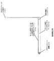
図2は、ここに記載される幾つかの実施形態を代表する表示装置200を有する例えば図1のモバイル装置100などのモバイル装置の側面図である。図示されるように、モバイル装置100はモバイルベース(本体)210を有している。多くのモバイル装置において通常、モバイルベース210は入力装置及び/又は組み込み表示スクリーン214を有し得る。表示装置200は、透明カバーを縦方向の観察位置に変えることによって起動される、従来からのディスプレイに加えての補助ディスプレイ又は追加ディスプレイとして使用され得る。モバイルベース210は更に、モバイル装置に典型的な幾つかの他の処理タスクのうちの何れかに加えて、ホログラフィック光学素子を用いる補助表示装置用の画像を作り出すために使用され得るプロセッサ及びメモリ(図5に関連して説明する)を有する。
FIG. 2 is a side view of a mobile device, such as the
ホログラフィック光学素子(HOE)230を介して眺められることになる実像を生成するプロジェクション装置220が、モバイルベース210に動作的に結合される。HOEは、回転可能なヒンジ212を介してモバイルベース210に取り付けられた薄くて透明な(あるいは、実施形態に応じて部分的に透明若しくは半透明な)表面である。収容位置又は非動作位置において、HOE230は単に、モバイル装置100の主の表示スクリーン214のカバーとなる。展開位置又は動作位置においては、図2に示されるように、HOE230は、プロジェクション装置220の実像を、HOE230を通して見るときにユーザに視認可能な虚像へと変換する。このモードにおいて、HOE230は、それを通すことでプロジェクション装置220による表示画像の投影された(且つ拡大された)ビューが視認可能になるウィンドウとして機能する。換言すれば、ホログラフィック光学素子(HOE)230は、プロジェクション装置220によって投影された、発散する変調された実像を反射して、モバイル装置の操作者(ここでは、ビューアとも呼ぶ)の方に向けられた虚像にする。
A
特定の実施形態において、プロジェクション装置220からの光は、操作者から遠ざかるようにHOE230の方に向けられることができ、そしてHOE230は、この光を変換してモバイル装置100の操作者(又は、より具体的には人間オペレータの眼)の方に向け戻すことができる。また、一部の実施形態において、HOE230は、モバイルベース210に平行で近接した、展開されずに“閉じた”使用不可能位置(図示せず)から、モバイルベース210に実質的に垂直とし得る展開された“開いた”使用可能位置(図2に示す)へと、HOE230が回転移動されることを可能にする回転可能なヒンジ212で、モバイルベース210に動作的に結合され得る。
In certain embodiments, light from the
図3は、表示装置の様々なコンポーネントの動作を例示する図2のモバイル装置及び表示装置の側面図である。図4は、表示装置の一例の動作方法の一実施形態に係る動作フローである。 FIG. 3 is a side view of the mobile device and display device of FIG. 2 illustrating the operation of various components of the display device. FIG. 4 is an operation flow according to an embodiment of the operation method of the example of the display device.
図3及び4に関し、ステップ410にて、モバイルベース210が補助画像を計算する。すなわち、当業者に認識された既知の技術のうちの何れかを用いて、プロジェクション装置220をして特定の発散する変調された実像をHOE230に向けて放射させるために、単純な表示計算を必要とするものを実行する。この画像は、主ディスプレイ214上に示される画像の単純なコピーであってもよいし、主ディスプレイ214上の1つと展開位置にあるHOE230上の1つという2つの独立した表示エリアをモバイル装置100に効果的に提供するよう、異なるビューを含んでいてもよい。HOE230はまた、補助画像がHOE230上に表示されているときは主ディスプレイ214が無効にされるよう、代替表示装置として使用されてもよい。
3 and 4, at
ステップ420にて、これらの計算結果がプロジェクション装置220によって使用されて、発散する変調された実像310(矢印Aで示す方向のその発散境界を破線で表す)がHOE230に向けて放射され得る。
At
ステップ430にて、HOE230が、発散する変調された実像310を変換して操作者240の方に反射し、コリメートされた(すなわち、平行な光線を有する)虚像320(矢印Cで示す方向の発散も収束もしないその“無限”境界を平行な破線で表す)を形成する。操作者240は、コリメートされた虚像320が通る空間ボリュームの境界によって表される“アイボックス(eyebox)”内に自身の眼があるときにこの像を見ることができる。
At
ステップ440にて、アイボックス内に眼がある操作者240が、コリメートされた虚像320の全体のうちの小さい部分を、HOE230より遠い無限焦点距離にあり、且つその観察箇所に視認可能に存在する現実世界の地物250上に重ね合わされた、収束する知覚画像330(矢印Bで示す方向のその収束境界を破線で表す)として知覚する。
At
幾つかの実施形態において、プロジェクション装置220は、直径がほんの数ミリメートル(mm)の実像を生成するように動作し得る。幾つかのそのような実施形態において、内部投影面(“ディスプレイ”とも呼ぶ)は、LCOSプロジェクタで使用される液晶・オン・シリコン(LCOS)デバイス、又はDLP(デジタル・ライト・プロセッシング)プロジェクタで使用されるデジタルマイクロミラーデバイス(DMD)の何れかを有し得る。LCOS及びDMDの両デバイスは、少ない電力のみを動作に使用するとともに、集積回路のサイズほどである。従って、これらのデバイスは、組み込み表示スクリーンと共存して、その下方でモバイル装置100の正面エッジ内に集積され得る。
In some embodiments, the
LCOS及びDMDなるデバイスは、自身では光を作り出さない光変調器であり、その代わりに、これらのデバイスは、これまたプロジェクション装置220に組み込まれる外部光源を使用する。この光源から放射された光は、LCOS又はDMDの表面へとコリメートされ、そこで画像ディテールで変調される。典型的な投影アプリケーション(例えば、投影式テレビジョンで使用されるLCOSプロジェクション及びDLPプロジェクション)では、この変調された光は、拡大をも提供する対物レンズを用いて拡散反射スクリーン上に投影され得る。しかしながら、ここに開示される様々なプロジェクション装置220の実施形態では、対物レンズは使用されず、その代わりに、光源を有する照明光学系が、画像投影の変調光がHOE上に均等に及ぶように特別に設計される。故に、プロジェクション装置220は、発散する変調された実像をHOE230上に投影する(すなわち、HOEの位置から実像を眺めることができる)。さらに、幾つかの実施形態において、プロジェクション装置220によって投影される光は、HOE230に関してここに記載される理由により、1つの波長(すなわち、単色)、又は一組の波長、例えば赤、緑及び青の波長のうちの各々1つに対応する一組の波長(すなわち、三色)など、に制限され得る。
The LCOS and DMD devices are light modulators that do not produce light themselves; instead, they use an external light source that is also incorporated into the
一部の実施形態において、HOE230は、凹面鏡のように(例えば、化粧用の拡大鏡のように)機能するように設計される。実際、透明性の利益を無視すれば、HOE230は、プロジェクション装置220からの発散する変調された実像を、それが“無限遠で”操作者に向けて投影された所望の虚像(すなわち、発散も収束もしない)として現れるように反射(及び拡大)する凹面鏡で置き換えられてもよい。しかしながら、透明性を欠くことに加えて、そのようなミラーはHOE230のような平坦表面を特徴とせず、このことは、凹面鏡を幾分、フラットなモバイルベース210を有するモバイル装置100での使用には非実用的なものにする。故に、一部の実施形態において、HOE230は、凹面鏡のように機能しながらも、モバイルベース210に一層と適合する平坦表面と透明性という更なる特徴をも提供するように、設計され得る。
In some embodiments, the
これを達成するため、一実施形態において、HOE230は、活性なHOE230材料の厚さが光の波長より遥かに大きいものであるブラッグ回折型とし得る。一部の実施形態では、例えば、HOE230は、適切に露光・現像されるときに屈折率において相異なる非常に小さい透明領域群を持つ3D微細構造を保有することになる重クロム酸ゼラチンを有し得る。これらの微細構造のサイズは、可視光の波長に近い100ナノメートル(nm)程度とすることができ、異なる屈折率を持つ異なる微細構造は、既知の技術を用いて、凹面鏡と同じ光反射特性を生み出しながらも、透明且つ平坦であるという更なる利点をも有するように、HOE230内に作り出され得る。
To accomplish this, in one embodiment, the
この凹面鏡効果は、HOE230内の3D微細構造によるものであり、HOE230の3D微細構造内で起こるブラッグ回折が、整合する波長の光のみが屈折されることを可能にするフィルタとして作用することによる。故に、HOE230は、プロジェクション装置220からの光の特定の波長のみにブラッグ回折条件が当てはまり、さもなければ透明であるHOE230をその他すべての波長が大きく影響されずに通過するように、設計され得る。
This concave mirror effect is due to the 3D microstructure in the
特定の実施形態では、HOE230は、プロジェクション装置220からの発散する変調された実像“光”に対する高い回折効率を達成するように比較的厚くされることができ(例えば、0.5mm)、HOE230は、非常に低い散乱効率を有するHOE材料を使用し得る(すなわち、HOE230を通過する“その他の波長”を持つ光のうちの非常に小さい部分のみが、HOE230による影響を受ける)。プロジェクション装置220からの光に対する高回折効率を達成するため、厚いHOE230が使用され得る。何故なら、HOE230は、ディスプレイからの光を効率的に反射するために、光と建設的に干渉する多数の散乱3D構造を用いるからである。故に、HOE230は、非常に小さい波長範囲からの光を反射すること及び非常に小さい許容角度からの光を反射すること(これらは何れも、HOE230が実質的に透明であることを保証する特性である)のうちで選択的であるように設計され得る。このようなホログラフィック記憶素子としての使用に関して当業者に知られたこのような特性を備えた、数多くのフォトポリマーが存在する。
In certain embodiments, the
様々な実施形態のHOE230は、プロジェクション装置220からの光を変換してビューアの眼の方に向け直す拡大鏡として実効的に機能してもよい。また、当業者に知られた技術を用いて、80%より高い回折効率を有するHOE230を構築することが可能であり、これは、HOE230によってプロジェクション装置220からの光がより多くビューアの眼の方に向け直されることを意味する。さらに、プロジェクション装置220とHOE230とがあわさって、光の殆どがビューアの眼が位置する空間内の領域に集められることを確保するように動作することができる。これは、全体的な光効率を大いに高めるものであり、また、モバイル装置100が如何なる種類のディフューザも使用しないために達成されるものである。これは、ひいては、表示される像が明るく(太陽光に適合)且つ/或いは電力効率的であることを意味する。さらに、空間のうちの非常に小さい領域からしか表示を観察することができないため、これらの様々な実施形態は、表示コンテンツのプライバシーを確保する助けとなることができる。
The
さらに、特定の実施形態では、プロジェクション装置220用の光源は、HOE230の許容波長帯域内に発光を集中させるように動作してもよく、これは、一部の実施形態では、1つの波長の光(例えば、緑色光)のみを使用する単色プロジェクション装置220の使用を有し得る。他の実施形態において、HOE230は、赤色光、緑色光及び青色光の各々である3つの狭帯域の光に対して同時に動作するように設計されてもよく、そのような実施形態では、プロジェクション装置220はそれら3つの波長での発光を使用し得る。
Further, in certain embodiments, the light source for the
一部の実施形態によって使用される光源は、比較的効率的で単色で焦点合わせが容易な固体レーザを有し得る。そのようなレーザはコストが掛かるとともに“スペックル効果”(これは単色性に由来する)を有することがあるが、後者は、(プロジェクション装置220の光路内に追加コンポーネントを使用することになり得るものの)発光の位相を素早く変調することによって最小化され得る。他の実施形態は、光源としてLEDを使用し得るが、これもまた、一部の光が失われるという犠牲の下で、LEDの発光帯域を狭めるために追加の干渉フィルタを有することになり得る。 The light source used by some embodiments may have a solid laser that is relatively efficient, monochromatic and easy to focus. Such lasers can be costly and have a “speckle effect” (which is derived from monochromaticity), but the latter (uses additional components in the optical path of the projection device 220). It can be minimized by quickly modulating the phase of the emission. Other embodiments may use an LED as the light source, but this may also have an additional interference filter to narrow the LED's emission band at the expense of some light loss. .
追加の特徴として、操作者によって見られる画像は、固定された表面領域を充たすものではなく、或る一定の立体角に及ぶものである。従って、画像の見た目の大きさは、モバイル装置の実際のサイズより遥かに大きくなることができる。実際、モバイル装置100上のHOE230は、それを通して表示画像を見るウィンドウのように作用し、モバイル装置100を操作者の眼240に近づけることによって、より大きい表示面積が現実となる。とりわけ、HOE230が操作者の眼240に非常に近づけられたときであっても、虚像は遥か遠くに現れるので、操作者に近接させても眼精疲労を引き起こすことはない。
As an additional feature, the image seen by the operator does not fill a fixed surface area, but covers a certain solid angle. Thus, the apparent size of the image can be much larger than the actual size of the mobile device. In fact, the
表示装置200は、HOE230を用いて、該HOEの透明表面を通して眺められる現実世界に重なって出現する虚像を作り出すので、この装置は、やはりモバイル装置に動作的に結合されて無線ネットワーク接続(例えば、WiFi)を介して別の遠隔ビューアに同じビューを中継するカメラ、とともに使用されることができる。そのような利用法では、遠隔ユーザは、ポインティング装置を用いて視野内のオブジェクトを指し示し得る。この情報はモバイル装置に中継して戻されることができ、モバイル装置は、上述の表示を用いて、現実世界のビュー上にポインタを重ね合わせ得る。これは基本的に、例えば音声接続だけでは情報を伝えることが困難な場合に問題を手助けするために、遠隔ビューアからの対話式の支援を可能にする。
The display device 200 uses the
さらに、表示スクリーン214を通じて見られる環境のビューに表示画像がアライメント(位置合わせ)される場合、このモバイル装置は、表示スクリーン214上で見た情報を外界のビューに移すことをユーザに要求しない感動的な拡張現実装置となる。このアライメントは、モバイル装置内の慣性センサ(MEMS加速度計及びジャイロスコープ)、磁気コンパス、及び/又はGPS受信器を当てにし得る。画像安定化もモバイル装置のカメラを使用し得る。なお、カメラが使用される場合、そのビデオストリームを用いて姿勢情報を決定することができ、従来からの表示に使用されるような合成画像又は重ね合わせ画像が生成することにはビデオは必要とされない。例えば、モバイルベース210が有するプロセッサが、内蔵カメラを使用して、表示面を通して視認可能な少なくとも1つの背景の特徴を決定し、検出された背景の特徴に基づいて画像コンピューテーションを実行し得る。
In addition, if the display image is aligned with the view of the environment viewed through the
一実施形態において、モバイル装置は、ホログラフィック光学素子を有し且つ当該モバイル装置に結合された透明な表示面を通して見ている当該モバイル装置の操作者によって見られる環境のビューに基づいて、表示パラメータを決定してもよい。決定されたこれら表示パラメータは、環境にアライメントされた表示画像を操作者に導くために、モバイル装置のプロジェクション装置から表示面上に表示画面を投影するための画像コンピューテーションを実行することに使用され得る。 In one embodiment, the mobile device has display parameters based on a view of the environment seen by an operator of the mobile device having a holographic optical element and looking through a transparent display surface coupled to the mobile device. May be determined. These determined display parameters are used to perform image computation to project the display screen from the projection device of the mobile device onto the display surface to guide the display image aligned to the environment to the operator. Can be done.
一実施形態において、HOE230は、如何なる電子装置も有さずに例えば光学グレードのプラスチックからなる受動部品である。一実施形態において、HOE230は、モバイル装置の従来からの表示スクリーンの保護カバーとして作用し得る。また、HOE230は、電気接続を使用しないので、容易に取り外し可能且つ取り換え可能にされ得る。
In one embodiment, the
HOE230にエンコードされる伝達関数は、プロジェクション装置220によって放射される光の波長に依存し得る。例えば、赤色光と緑色光とでは、同じ拡大率及びその他の特性を有しながらも横方向にずれた2つの異なる虚像が作り出され得る。このことは、フルRGBの色再現性が望ましい場合に、すなわち、隣り合わせに搭載された赤、緑及び青の3原色ごとに1つの3つのディスプレイ200が使用される場合に、ディスプレイ200を単純化するために活用されることができる。この構成は、3色の画像を融合するためにさもなければ必要となるダイクロイックコンバイナ光学系の必要性を排除する。同様に、これは表示装置を単純化する。何故なら、3つの表示装置の各々を1つの色のみに関して最適化することができ、故に、カラーフィルタ及び/又は多色光源の必要性が排除されるからである。
The transfer function encoded in the
図5は、ここに開示される数多くの実施形態がともに使用され得る一例に係るモバイル装置500の設計を示すブロック図である。この設計は、好適なコンピューティング環境の単なる一例であり、用途又は機能の範囲について何らかの限定を示唆することを意図したものではない。数多くのその他の汎用あるいは専用のモバイル装置環境又はモバイル装置構成も使用され得る。モバイル装置500は、携帯電話、端末、ハンドセット、PDA、スマートフォン、無線モデム、コードレス電話などとし得る。このモバイル装置は、例えば符号分割多重アクセス(CDMA)システムやグローバル・システム・フォー・モバイル・コミュニケーションズ(GMS)システムなどの無線通信システムとともに使用され得る。
FIG. 5 is a block diagram illustrating a design of an example
モバイル装置500は、受信パス及び送信パスを介して双方向通信を提供することができる。受信パス上で、基地局によって送信された信号が、アンテナ512によって受信され、受信器(RCVR)514に提供される。受信器514は、受信信号の状態を整えてデジタル化し、サンプル群を更なる処理のためにデジタル部(デジタルセクション)520に提供する。送信パス上で、送信器(TMTR)516が、送信されるべきデータをデジタル部520から受信し、該データを処理して状態を整え、アンテナ512を介して基地局へと送信される変調信号を生成する。受信器514及び送信器516は、CDMAやGSM(登録商標)などをサポートするトランシーバの一部であってもよい。
The
デジタル部520は、例えば、モデムプロセッサ522、縮小命令セットコンピュータ/デジタル信号プロセッサ(RISC/DSP)524、コントローラ/プロセッサ526、内部メモリ528、汎用オーディオエンコーダ532、汎用オーディオデコーダ534、グラフィックス/表示プロセッサ536、及び外部バスインタフェース(EBI)538など、様々な処理ユニット、インタフェースユニット及びメモリユニットを含んでいる。モデムプロセッサ522は、例えば符号化、変調、復調及び復号化といった、データの送信及び受信に関する処理を実行し得る。RISC/DSP524は、モバイル装置500に関する汎用処理及び専用処理を実行し得る。コントローラ/プロセッサ526は、デジタル部520内の様々な処理ユニット及びインタフェースユニットの動作を指示し得る。内部メモリ528は、デジタル部520内の様々なユニットに関するデータ及び/又は命令を格納し得る。
The
汎用オーディオエンコーダ532は、オーディオソース542やマイク543からの入力信号の符号化を実行し得る。汎用オーディオデコーダ534は、符号化されたオーディオデータの復号化を実行し、出力信号をスピーカ/ヘッドホン544に提供し得る。グラフィックス/表示プロセッサ536は、表示ユニット546に与えられ得るグラフィックス、ビデオ、画像、及びテキストの処理を実行し得る。EBI538は、デジタル部520とメインメモリ548との間でのデータの伝送を支援し得る。デジタル部520は、1つ以上のプロセッサ、DSP、マイクロプロセッサ、RISCなどで実装され得る。デジタル部520はまた、1つ以上の特定用途向け集積回路(ASIC)及び/又は何らかのその他の種類の集積回路(IC)上に製造されてもよい。
The general-
コンピュータによって実行される例えばプログラムモジュールなどのコンピュータ実行可能命令が使用され得る。一般に、プログラムモジュールは、特定のタスクの実行又は特定の抽象データ型の実装を行うルーチン、プログラム、オブジェクト、コンポーネント、データ構造などを含む。分散コンピューティング環境が使用されてもよく、その場合、通信ネットワーク又はその他のデータ伝送媒体を介してリンクされた複数の遠隔処理装置によってタスクが実行される。分散コンピューティング環境において、プログラムモジュール又はその他のデータは、メモリ記憶装置を含んだローカル及び遠隔の双方のコンピュータ記憶媒体に置かれ得る。 Computer-executable instructions, such as program modules, executed by a computer may be used. Generally, program modules include routines, programs, objects, components, data structures, etc. that perform particular tasks or implement particular abstract data types. A distributed computing environment may be used, in which case tasks are performed by multiple remote processing devices that are linked through a communications network or other data transmission medium. In a distributed computing environment, program modules or other data may be located in both local and remote computer storage media including memory storage devices.
一般に、ここに記載される何れの装置も、例えばワイヤレス電話、携帯電話、ラップトップコンピュータ、無線マルチメディア装置、無線通信パーソナルコンピュータ(PC)カード、PDA、外部モデム若しくは内部モデム、無線チャネルを介して通信する装置など、様々な種類の装置を表し得る。装置は、例えばアクセス端末(AT)、アクセスユニット、加入者装置、移動局、モバイル装置、モバイルユニット、携帯電話、モバイル、遠隔ステーション、遠隔端末、遠隔ユニット、ユーザ装置、ユーザ機器、ハンドヘルド装置など、様々な名称を有し得る。ここに記載される何れの装置も、命令及びデータを格納するメモリと、ハードウェア、ソフトウェア、ファームウェア、又はこれらの組み合わせとを有し得る。 In general, any of the devices described herein can be via, for example, a wireless telephone, a cellular phone, a laptop computer, a wireless multimedia device, a wireless communication personal computer (PC) card, a PDA, an external or internal modem, a wireless channel Various types of devices may be represented, such as devices that communicate. The device can be, for example, an access terminal (AT), access unit, subscriber device, mobile station, mobile device, mobile unit, mobile phone, mobile, remote station, remote terminal, remote unit, user device, user equipment, handheld device, etc. Can have various names. Any device described herein may have memory for storing instructions and data, and hardware, software, firmware, or a combination of these.
ここに記載される様々な技術は、ハードウェア、ファームウェア、ソフトウェア、又はこれらの組み合わせにて実装され得る。当業者が更に認識するように、ここで本開示に関連して記載される様々な例示の論理ブロック、モジュール、回路、及びアルゴリズムステップは、エレクトロニクスハードウェア、コンピュータソフトウェア、又はこれらの双方の組み合わせとして実装され得る。ハードウェアとソフトウェアとのこの交換可能性をはっきり示すために、様々な例示のコンポーネント、ブロック、モジュール、回路、及びステップは、概してそれらの機能に関して上述されている。それらの機能がハードウェア又はソフトウェアの何れとして実装されるかは、具体的な用途と、システム全体に課される設計制約とに依存する。当業者は、記載の機能を、具体的な用途の各々に関して様々に実装し得るが、そのような実装の決定は、本開示の範囲からの逸脱を生じるものとして解釈されるべきでない。 Various techniques described herein may be implemented in hardware, firmware, software, or a combination thereof. As will be further appreciated by those skilled in the art, the various exemplary logic blocks, modules, circuits, and algorithm steps described herein in connection with this disclosure may be described as electronic hardware, computer software, or a combination of both. Can be implemented. To clearly illustrate this interchangeability between hardware and software, various example components, blocks, modules, circuits, and steps have been described above generally in terms of their functionality. Whether these functions are implemented as hardware or software depends on the specific application and design constraints imposed on the entire system. Those skilled in the art may implement the described functionality in various ways for each specific application, but such implementation decisions should not be construed as departing from the scope of the present disclosure.
ハードウェア実装の場合、これらの技術を実行するために使用される処理ユニットは、1つ以上のASIC、DSP、デジタル信号処理デバイス(DSPD)、プロググラム可能論理デバイス(PLD)、フィールドプログラマブルゲートアレイ(FPGA)、プロセッサ、コントローラ、マイクロコントローラ、マイクロプロセッサ、電子デバイス、ここに記載の機能を実行するように設計されたその他の電子ユニット、コンピュータ、又はこれらの組み合わせの中に実装され得る。 For hardware implementations, the processing units used to implement these technologies are one or more ASICs, DSPs, digital signal processing devices (DSPD), programmable logic devices (PLD), field programmable gate arrays. (FPGA), processor, controller, microcontroller, microprocessor, electronic device, other electronic unit designed to perform the functions described herein, a computer, or a combination thereof.
故に、ここに本開示に関連して記載される様々な例示の論理ブロック、モジュール、及び回路は、ここに記載の機能を実行するように設計された、汎用プロセッサ、DSP、ASIC、FPGA、又はその他のプログラム可能論理デバイス、ディスクリートのゲート若しくはトランジスタロジック、ディスクリートのハードウェア部品、又はこれらの組み合わせを用いて、実装あるいは実行され得る。汎用プロセッサはマイクロプロセッサとし得るが、他の例では、該プロセッサは、何らかの従来からのプロセッサ、コントローラ、マイクロコントローラ、又は状態機械であってもよい。プロセッサはまた、複数のコンピューティングデバイスの組み合わせとして実装されてもよく、例えば、DSPとマイクロプロセッサとの組み合わせ、複数のマイクロプロセッサ、DSPコアと連結された1つ以上のマイクロプロセッサ、又はその他のこのような構成として実装されてもよい。 Thus, the various exemplary logic blocks, modules, and circuits described herein in connection with this disclosure are general-purpose processors, DSPs, ASICs, FPGAs, or circuits designed to perform the functions described herein. It can be implemented or implemented using other programmable logic devices, discrete gate or transistor logic, discrete hardware components, or combinations thereof. A general purpose processor may be a microprocessor, but in other examples, the processor may be any conventional processor, controller, microcontroller, or state machine. A processor may also be implemented as a combination of multiple computing devices, such as a combination of a DSP and a microprocessor, multiple microprocessors, one or more microprocessors coupled to a DSP core, or other such. You may implement as such a structure.
ファームウェア及び/又はソフトウェア実装の場合、これらの技術は、例えばランダムアクセスメモリ(RAM)、読み出し専用メモリ(ROM)、不揮発性ランダムアクセスメモリ(NVRAM)、プログラム可能読み出し専用メモリ(PROM)、電気的消去可能PROM(EEPROM)、FLASHメモリ、コンパクトディスク(CD)、磁気データ記憶装置若しくは光データ記憶装置、又はこれらに類するものなどの、コンピュータ読み取り可能媒体に格納された命令として具現化され得る。これらの命令は、1つ以上のプロセッサによって実行可能であり、ここに記載の機能の特定の態様をそれらのプロセッサに実行させ得る。 For firmware and / or software implementations, these techniques include, for example, random access memory (RAM), read only memory (ROM), non-volatile random access memory (NVRAM), programmable read only memory (PROM), electrical erasure It may be embodied as instructions stored on a computer readable medium, such as a possible PROM (EEPROM), FLASH memory, compact disk (CD), magnetic data storage device or optical data storage device, or the like. These instructions are executable by one or more processors and may cause those processors to perform certain aspects of the functionality described herein.
ソフトウェアにて実装される場合、これらの機能は、コンピュータ読み取り可能媒体上の1つ以上の命令又はコードとして格納あるいは伝送され得る。コンピュータ読み取り可能媒体は、コンピュータ記憶媒体と、1つの場所から別の場所へのコンピュータプログラムの転送を支援する何らかの媒体を含んだ通信媒体との双方を含む。記憶媒体は、汎用あるいは専用のコンピュータによってアクセスされることができる何らかの利用可能な媒体とし得る。限定ではなく、例として、そのようなコンピュータ読み取り可能媒体は、RAM、ROM、EEPROM、CD−ROM若しくはその他の光ディスクストレージ、磁気ディスクストレージ若しくはその他の磁気記憶装置、又は、所望のプログラムコード手段を命令若しくはデータ構造の形態で搬送あるいは格納するために使用されることが可能で、汎用あるいは専用のコンピュータ若しくは汎用あるいは専用のプロセッサによってアクセスされることが可能なその他の媒体を有することができる。また、接続も適宜、コンピュータ読み取り可能媒体と称される。例えば、ソフトウェアがウェブサイト、サーバ又はその他の遠隔ソースから同軸ケーブル、光ファイバケーブル、ツイストペア、デジタル加入者回線(DSL)、又は例えば赤外線、無線若しくはマイクロ波などの無線技術を用いて伝送される場合、同軸ケーブル、光ファイバケーブル、ツイストペア、DSL、又は例えば赤外線、無線若しくはマイクロ波などの無線技術は、コンピュータ読み取り可能媒体の定義に含まれる。ディスク(disk及びdisc)は、ここでは、CD、レーザディスク、光ディスク、デジタル多用途ディスク(DVD)、フロッピー(登録商標)ディスク、及びブルーレイディスクを含み、diskは通常、磁気的にデータを再生し、discはレーザを用いて光学的にデータを再生する。以上のものの組み合わせもコンピュータ読み取り可能媒体の範囲内に含められるべきである。 If implemented in software, the functions may be stored or transmitted as one or more instructions or code on a computer-readable medium. Computer-readable media includes both computer storage media and communication media including any medium that facilitates transfer of a computer program from one place to another. A storage media may be any available media that can be accessed by a general purpose or special purpose computer. By way of example, and not limitation, such computer readable media can be RAM, ROM, EEPROM, CD-ROM or other optical disk storage, magnetic disk storage or other magnetic storage device, or any desired program code means. Alternatively, it can have other media that can be used to carry or store in the form of a data structure and that can be accessed by a general purpose or special purpose computer or a general purpose or special purpose processor. Connections are also referred to as computer readable media as appropriate. For example, when the software is transmitted from a website, server or other remote source using coaxial cable, fiber optic cable, twisted pair, digital subscriber line (DSL), or wireless technology such as infrared, wireless or microwave Coaxial cable, fiber optic cable, twisted pair, DSL, or wireless technology such as infrared, wireless or microwave is included in the definition of a computer readable medium. Discs (disks and discs) here include CDs, laser discs, optical discs, digital versatile discs (DVDs), floppy discs, and Blu-ray discs, and discs usually play data magnetically. , Disc reproduces data optically using a laser. Combinations of the above should also be included within the scope of computer-readable media.
ソフトウェアモジュールは、RAMメモリ、フラッシュメモリ、ROMメモリ、EPROMメモリ、EEPROMメモリ、レジスタ、ハードディスク、リムーバブルディスク、CD−ROM、又は技術的に知られたその他の形態の記憶媒体内にあり得る。プロセッサが記憶媒体から情報を読み出し、記憶媒体に情報を書き込むことができるように、プロセッサに記憶媒体が結合される。他の例では、記憶媒体はプロセッサに集積されてもよい。プロセッサ及び記憶媒体はASIC内にあってもよい。ASICはユーザ端末内にあり得る。他の例では、プロセッサ及び記憶媒体は、個別部品としてユーザ端末内にあってもよい。 A software module may be in RAM memory, flash memory, ROM memory, EPROM memory, EEPROM memory, registers, hard disk, removable disk, CD-ROM, or other form of storage medium known in the art. A storage medium is coupled to the processor such that the processor can read information from, and write information to, the storage medium. In other examples, the storage medium may be integrated into the processor. The processor and the storage medium may be in an ASIC. The ASIC can be in the user terminal. In another example, the processor and the storage medium may be in the user terminal as individual components.
例示の実施形態は、1つ以上の独立型コンピュータシステムの状況でここに開示された事項の態様を利用することに言及しているかもしれないが、これらの事項は、そのように限定されず、むしろ、例えばネットワークコンピューティング環境又は分散コンピューティング環境などの任意のコンピューティング環境との関連で実現されてもよい。さらに、ここに開示された事項の態様は、複数の処理チップ若しくは装置の内部で、あるいはそれらに跨って実現されてもよく、ストレージも同様に、複数の装置に跨って実現され得る。そのような装置は、例えば、パーソナルコンピュータ、ネットワークサーバ、及びハンドヘルド装置を含み得る。 Although the exemplary embodiments may refer to utilizing aspects of the subject matter disclosed herein in the context of one or more stand-alone computer systems, these matters are not so limited. Rather, it may be implemented in the context of any computing environment, such as a network computing environment or a distributed computing environment. Furthermore, aspects of the matters disclosed herein may be realized within or across a plurality of processing chips or devices, and storage may also be realized across a plurality of devices. Such devices can include, for example, personal computers, network servers, and handheld devices.
以上、これらの事項を構造的機構及び/又は方法行為に特有の言葉で説明してきたが、理解されるように、添付の請求項に規定される事項は必ずしも、上述の特定の機構又は行為に限定されるものではない。むしろ、上述の特定の機構及び行為は、請求項を実現する形態例として開示されたものである。 Although the foregoing has been described in terms specific to structural mechanisms and / or method actions, it will be understood that the matters defined in the appended claims do not necessarily refer to the specific mechanisms or actions described above. It is not limited. Rather, the specific features and acts described above are disclosed as example forms of implementing the claims.
Claims (10)
画像を表示するよう前記モバイルベースに動作的に結合されたプロジェクション装置と、
前記プロジェクション装置によって投影された表示画像を導くよう前記モバイルベースに動作的に結合され且つホログラフィック光学素子を有する透明な表示面と、
を有するモバイル装置。 A mobile base having a processor and memory for producing images;
A projection device operably coupled to the mobile base to display an image;
A transparent display surface operatively coupled to the mobile base and having a holographic optical element to direct a display image projected by the projection device;
Mobile device having
表示面が表示画像を前記モバイル装置の操作者へと導くよう、プロジェクション装置からホログラフィック光学素子を有する透明な前記表示面上に前記表示画像を投影するための画像計算を実行することと、
前記プロジェクション装置から前記表示面上に前記表示画像を投影することと、
を有する方法。 A method for displaying an image on a mobile device, comprising:
Performing an image calculation for projecting the display image from the projection device onto the transparent display surface having holographic optical elements such that the display surface guides the display image to an operator of the mobile device;
Projecting the display image from the projection device onto the display surface;
Having a method.
ホログラフィック光学素子を有し且つ前記モバイル装置に結合された透明な表示面を通して見ている前記モバイル装置の操作者によって見られる環境の眺めに基づいて、表示パラメータを決定させ、且つ
前記環境にアライメントされた表示画像を前記操作者へと導くよう、前記モバイル装置に結合されたプロジェクション装置から前記透明な表示面上に前記表示画像を投影するための画像計算を実行させる
命令を有する、コンピュータ読み取り可能媒体。 A computer readable medium having computer readable instructions for an augmented reality mobile device, wherein the computer readable instructions are
Display parameters are determined based on a view of the environment seen by an operator of the mobile device having a holographic optical element and viewed through a transparent display surface coupled to the mobile device, and aligned with the environment Computer readable having instructions for performing image calculations for projecting the display image onto the transparent display surface from a projection device coupled to the mobile device to guide the displayed image to the operator Medium.
Applications Claiming Priority (3)
| Application Number | Priority Date | Filing Date | Title |
|---|---|---|---|
| US13/354,353 US9581814B2 (en) | 2012-01-20 | 2012-01-20 | Transparent display for mobile device |
| US13/354,353 | 2012-01-20 | ||
| PCT/US2013/020711 WO2013109435A1 (en) | 2012-01-20 | 2013-01-09 | Transparent display for mobile device |
Publications (2)
| Publication Number | Publication Date |
|---|---|
| JP2015515636A true JP2015515636A (en) | 2015-05-28 |
| JP2015515636A5 JP2015515636A5 (en) | 2016-02-18 |
Family
ID=48796867
Family Applications (1)
| Application Number | Title | Priority Date | Filing Date |
|---|---|---|---|
| JP2014553318A Pending JP2015515636A (en) | 2012-01-20 | 2013-01-09 | Transparent display for mobile devices |
Country Status (6)
| Country | Link |
|---|---|
| US (1) | US9581814B2 (en) |
| EP (1) | EP2805206A4 (en) |
| JP (1) | JP2015515636A (en) |
| KR (1) | KR20140117426A (en) |
| CN (1) | CN104054027B (en) |
| WO (1) | WO2013109435A1 (en) |
Families Citing this family (21)
| Publication number | Priority date | Publication date | Assignee | Title |
|---|---|---|---|---|
| ES2540029B1 (en) * | 2013-09-11 | 2016-04-13 | Universidad Carlos Iii De Madrid | Accessory for viewing in projection rooms accessibility elements associated with audiovisual content |
| US9606506B2 (en) * | 2013-10-15 | 2017-03-28 | Microsoft Technology Licensing, Llc | Holographic interaction device |
| US9779474B2 (en) * | 2014-04-04 | 2017-10-03 | Blackberry Limited | System and method for electronic device display privacy |
| US10365482B1 (en) * | 2014-05-15 | 2019-07-30 | Rockwell Collins, Inc. | Light control system |
| ES2585604B2 (en) * | 2015-04-06 | 2017-04-05 | Interactive Movies S.L. | Virtual imaging device and procedure based on thin sheets with defined reflectance |
| WO2017116426A1 (en) * | 2015-12-30 | 2017-07-06 | Hewlett-Packard Development Company, L.P. | Detachable electronic device |
| CN105719586A (en) * | 2016-03-18 | 2016-06-29 | 京东方科技集团股份有限公司 | Transparent display method and device |
| DE102016108878A1 (en) * | 2016-05-13 | 2017-11-16 | Visteon Global Technologies, Inc. | Display unit and method for displaying information |
| KR101866049B1 (en) * | 2016-08-30 | 2018-06-11 | (주)에이스테크 | HUD type mobile phone case |
| CN107213588A (en) * | 2017-06-28 | 2017-09-29 | 湖州积微电子科技有限公司 | One kind office treadmill |
| KR102485447B1 (en) | 2017-08-09 | 2023-01-05 | 삼성전자주식회사 | Optical window system and see-through type display apparatus including the same |
| ES2708898A1 (en) * | 2017-10-11 | 2019-04-11 | Peces Ruben Rios | Bidirectional Virtual Image Projector (Machine-translation by Google Translate, not legally binding) |
| US11650422B2 (en) | 2017-10-23 | 2023-05-16 | Vuzix Corporation | Active correction of aberrations in optical systems |
| US11188154B2 (en) * | 2018-05-30 | 2021-11-30 | International Business Machines Corporation | Context dependent projection of holographic objects |
| US11258890B2 (en) | 2018-07-30 | 2022-02-22 | IKIN, Inc. | Portable terminal accessory device for holographic projection and user interface |
| CN114096922A (en) * | 2019-03-11 | 2022-02-25 | 艾肯公司 | Portable terminal accessory device for holographic projection and user interface |
| KR20210117418A (en) * | 2020-03-19 | 2021-09-29 | 삼성전자주식회사 | Standing device for providing screen of electronic device as hologram |
| WO2022045707A1 (en) | 2020-08-25 | 2022-03-03 | Samsung Electronics Co., Ltd. | Augmented reality device based on waveguide with holographic diffractive grating structure and apparatus for recording the holographic diffractive grating structure |
| USD994011S1 (en) | 2021-06-16 | 2023-08-01 | IKIN, Inc. | Holographic projection device |
| USD988277S1 (en) | 2021-06-17 | 2023-06-06 | IKIN, Inc. | Portable holographic projection device |
| USD1009969S1 (en) | 2021-06-17 | 2024-01-02 | IKIN, Inc. | Holographic device housing |
Citations (14)
| Publication number | Priority date | Publication date | Assignee | Title |
|---|---|---|---|---|
| JPS63187215A (en) * | 1987-01-29 | 1988-08-02 | Shimadzu Corp | Head-up display |
| JPH02148179U (en) * | 1989-05-17 | 1990-12-17 | ||
| JPH0392432A (en) * | 1989-09-05 | 1991-04-17 | Stanley Electric Co Ltd | Vehicle speed proportion type head-up display system |
| JPH08201718A (en) * | 1995-01-31 | 1996-08-09 | Nippondenso Co Ltd | Display device |
| JPH10311963A (en) * | 1997-02-14 | 1998-11-24 | Sextant Avionique | Head-up vision device having secondary image reduced |
| JP2000181375A (en) * | 1998-12-18 | 2000-06-30 | Shimadzu Corp | Terminal device for portable telephone set |
| JP2003029343A (en) * | 2001-07-13 | 2003-01-29 | Olympus Optical Co Ltd | Secret image display |
| US20030114200A1 (en) * | 2001-12-14 | 2003-06-19 | Samsung Electronics Co., Ldt. | Portable terminal device having a display unit utilizing a holographic screen |
| JP2004361559A (en) * | 2003-06-03 | 2004-12-24 | Sony Corp | Picture display system |
| JP2006262980A (en) * | 2005-03-22 | 2006-10-05 | Olympus Corp | Information terminal and virtual pet display method |
| JP2007517473A (en) * | 2003-12-31 | 2007-06-28 | シンボル テクノロジーズ, インコーポレイテッド | Power savings in laser projection displays by alternately emitting pulsed RGB lasers |
| JP2009003281A (en) * | 2007-06-22 | 2009-01-08 | Ricoh Co Ltd | Portable electronic equipment |
| JP2009134147A (en) * | 2007-11-30 | 2009-06-18 | Funai Electric Co Ltd | Portable terminal |
| JP2011248345A (en) * | 2010-05-26 | 2011-12-08 | Kofukin Seimitsu Kogyo (Shenzhen) Yugenkoshi | Portable electronic device |
Family Cites Families (19)
| Publication number | Priority date | Publication date | Assignee | Title |
|---|---|---|---|---|
| US3940204A (en) | 1975-01-23 | 1976-02-24 | Hughes Aircraft Company | Optical display systems utilizing holographic lenses |
| US4725142A (en) * | 1983-09-20 | 1988-02-16 | University Of Delaware | Differential holography |
| US6292305B1 (en) | 1997-08-25 | 2001-09-18 | Ricoh Company, Ltd. | Virtual screen display device |
| US7559895B2 (en) | 2000-07-07 | 2009-07-14 | University Of Pittsburgh-Of The Commonwealth System Of Higher Education | Combining tomographic images in situ with direct vision using a holographic optical element |
| US6637896B2 (en) | 2001-10-31 | 2003-10-28 | Motorola, Inc. | Compact projection system and associated device |
| GB2383641A (en) | 2001-12-21 | 2003-07-02 | Nokia Corp | Reflective displays |
| FI114945B (en) | 2002-09-19 | 2005-01-31 | Nokia Corp | Electrically adjustable diffractive gate element |
| US20060001596A1 (en) | 2004-06-30 | 2006-01-05 | Interdigital Technology Corporation | Method and system for displaying holographic images in mobile devices |
| JP2006071770A (en) | 2004-08-31 | 2006-03-16 | Olympus Corp | Superimposed type image viewing apparatus |
| US20060145947A1 (en) | 2005-01-04 | 2006-07-06 | Arneson Theodore R | Foldable electronic device with virtual image display |
| EP1849033B1 (en) | 2005-02-10 | 2019-06-19 | Lumus Ltd | Substrate-guided optical device utilizing thin transparent layer |
| WO2006092813A1 (en) * | 2005-03-02 | 2006-09-08 | Silvia Zambelli | Mobile holographic simulator of bowling pins and virtual objects |
| US7405881B2 (en) | 2005-05-30 | 2008-07-29 | Konica Minolta Holdings, Inc. | Image display apparatus and head mount display |
| EP1975675B1 (en) | 2007-03-29 | 2016-04-27 | GM Global Technology Operations LLC | Holographic information display |
| GB0718626D0 (en) * | 2007-05-16 | 2007-11-07 | Seereal Technologies Sa | Holograms |
| TWI425524B (en) | 2007-05-30 | 2014-02-01 | Opus Microsystems Corp | Head-up display system |
| JP2009008758A (en) | 2007-06-26 | 2009-01-15 | Fujinon Corp | Imaging device, camera module and portable terminal equipment |
| WO2009102731A2 (en) * | 2008-02-12 | 2009-08-20 | Qualcomm Mems Technologies, Inc. | Devices and methods for enhancing brightness of displays using angle conversion layers |
| WO2009117450A1 (en) | 2008-03-18 | 2009-09-24 | Invism, Inc. | Enhanced immersive soundscapes production |
-
2012
- 2012-01-20 US US13/354,353 patent/US9581814B2/en active Active
-
2013
- 2013-01-09 KR KR1020147020269A patent/KR20140117426A/en not_active Application Discontinuation
- 2013-01-09 CN CN201380006017.1A patent/CN104054027B/en active Active
- 2013-01-09 JP JP2014553318A patent/JP2015515636A/en active Pending
- 2013-01-09 WO PCT/US2013/020711 patent/WO2013109435A1/en active Application Filing
- 2013-01-09 EP EP13738478.0A patent/EP2805206A4/en not_active Withdrawn
Patent Citations (14)
| Publication number | Priority date | Publication date | Assignee | Title |
|---|---|---|---|---|
| JPS63187215A (en) * | 1987-01-29 | 1988-08-02 | Shimadzu Corp | Head-up display |
| JPH02148179U (en) * | 1989-05-17 | 1990-12-17 | ||
| JPH0392432A (en) * | 1989-09-05 | 1991-04-17 | Stanley Electric Co Ltd | Vehicle speed proportion type head-up display system |
| JPH08201718A (en) * | 1995-01-31 | 1996-08-09 | Nippondenso Co Ltd | Display device |
| JPH10311963A (en) * | 1997-02-14 | 1998-11-24 | Sextant Avionique | Head-up vision device having secondary image reduced |
| JP2000181375A (en) * | 1998-12-18 | 2000-06-30 | Shimadzu Corp | Terminal device for portable telephone set |
| JP2003029343A (en) * | 2001-07-13 | 2003-01-29 | Olympus Optical Co Ltd | Secret image display |
| US20030114200A1 (en) * | 2001-12-14 | 2003-06-19 | Samsung Electronics Co., Ldt. | Portable terminal device having a display unit utilizing a holographic screen |
| JP2004361559A (en) * | 2003-06-03 | 2004-12-24 | Sony Corp | Picture display system |
| JP2007517473A (en) * | 2003-12-31 | 2007-06-28 | シンボル テクノロジーズ, インコーポレイテッド | Power savings in laser projection displays by alternately emitting pulsed RGB lasers |
| JP2006262980A (en) * | 2005-03-22 | 2006-10-05 | Olympus Corp | Information terminal and virtual pet display method |
| JP2009003281A (en) * | 2007-06-22 | 2009-01-08 | Ricoh Co Ltd | Portable electronic equipment |
| JP2009134147A (en) * | 2007-11-30 | 2009-06-18 | Funai Electric Co Ltd | Portable terminal |
| JP2011248345A (en) * | 2010-05-26 | 2011-12-08 | Kofukin Seimitsu Kogyo (Shenzhen) Yugenkoshi | Portable electronic device |
Also Published As
| Publication number | Publication date |
|---|---|
| EP2805206A1 (en) | 2014-11-26 |
| EP2805206A4 (en) | 2014-11-26 |
| KR20140117426A (en) | 2014-10-07 |
| CN104054027A (en) | 2014-09-17 |
| US20130187950A1 (en) | 2013-07-25 |
| CN104054027B (en) | 2017-08-22 |
| US9581814B2 (en) | 2017-02-28 |
| WO2013109435A1 (en) | 2013-07-25 |
Similar Documents
| Publication | Publication Date | Title |
|---|---|---|
| US9581814B2 (en) | Transparent display for mobile device | |
| US11947117B2 (en) | Spatially multiplexed volume Bragg gratings with varied refractive index modulations for waveguide display | |
| CN108474956B (en) | Augmented reality display system with variable focus | |
| US20210199873A1 (en) | Dual-side antireflection coatings for broad angular and wavelength bands | |
| US20190227321A1 (en) | Rainbow reduction in waveguide displays | |
| US8989535B2 (en) | Multiple waveguide imaging structure | |
| US10073201B2 (en) | See through near-eye display | |
| TW202018369A (en) | Optical coupler, waveguide-based near-eye display and method of displaying images using waveguide-based near-eye display | |
| JP6391599B2 (en) | Optical system for near eye display | |
| US20220269076A1 (en) | Waveguide display with multiple monochromatic projectors | |
| US11885967B2 (en) | Phase structure on volume Bragg grating-based waveguide display | |
| US8902125B1 (en) | Reconfigurable handheld device | |
| KR20130039426A (en) | Mobile terminal and method for controlling thereof | |
| US20220291437A1 (en) | Light redirection feature in waveguide display | |
| US20220260836A1 (en) | Heterogeneous layered volume bragg grating waveguide architecture | |
| US11693248B1 (en) | TIR prisms and use of backlight for LCoS microdisplay illumination | |
| US20230314804A1 (en) | Polarization-recycling waveguided illumination system for microdisplay | |
| WO2022192303A1 (en) | Light redirection feature in waveguide display | |
| KR20240018666A (en) | Variable world blur for occlusion and contrast enhancement through tunable lens elements | |
| CN116964507A (en) | Light redirection features in waveguide displays |
Legal Events
| Date | Code | Title | Description |
|---|---|---|---|
| A521 | Request for written amendment filed |
Free format text: JAPANESE INTERMEDIATE CODE: A523 Effective date: 20151221 |
|
| A621 | Written request for application examination |
Free format text: JAPANESE INTERMEDIATE CODE: A621 Effective date: 20151221 |
|
| A977 | Report on retrieval |
Free format text: JAPANESE INTERMEDIATE CODE: A971007 Effective date: 20161020 |
|
| A131 | Notification of reasons for refusal |
Free format text: JAPANESE INTERMEDIATE CODE: A131 Effective date: 20161101 |
|
| A521 | Request for written amendment filed |
Free format text: JAPANESE INTERMEDIATE CODE: A523 Effective date: 20170131 |
|
| A131 | Notification of reasons for refusal |
Free format text: JAPANESE INTERMEDIATE CODE: A131 Effective date: 20170627 |
|
| A711 | Notification of change in applicant |
Free format text: JAPANESE INTERMEDIATE CODE: A711 Effective date: 20171102 |
|
| A131 | Notification of reasons for refusal |
Free format text: JAPANESE INTERMEDIATE CODE: A131 Effective date: 20180306 |
|
| A02 | Decision of refusal |
Free format text: JAPANESE INTERMEDIATE CODE: A02 Effective date: 20181023 |