JP2015515291A - Method for determining behavioral characteristics, posture characteristics, or geometric form characteristics of a person wearing glasses - Google Patents
Method for determining behavioral characteristics, posture characteristics, or geometric form characteristics of a person wearing glasses Download PDFInfo
- Publication number
- JP2015515291A JP2015515291A JP2014560422A JP2014560422A JP2015515291A JP 2015515291 A JP2015515291 A JP 2015515291A JP 2014560422 A JP2014560422 A JP 2014560422A JP 2014560422 A JP2014560422 A JP 2014560422A JP 2015515291 A JP2015515291 A JP 2015515291A
- Authority
- JP
- Japan
- Prior art keywords
- wearer
- image
- light source
- image sensor
- processing unit
- Prior art date
- Legal status (The legal status is an assumption and is not a legal conclusion. Google has not performed a legal analysis and makes no representation as to the accuracy of the status listed.)
- Withdrawn
Links
Images


Classifications
-
- G—PHYSICS
- G02—OPTICS
- G02C—SPECTACLES; SUNGLASSES OR GOGGLES INSOFAR AS THEY HAVE THE SAME FEATURES AS SPECTACLES; CONTACT LENSES
- G02C7/00—Optical parts
- G02C7/02—Lenses; Lens systems ; Methods of designing lenses
- G02C7/024—Methods of designing ophthalmic lenses
- G02C7/027—Methods of designing ophthalmic lenses considering wearer's parameters
-
- A—HUMAN NECESSITIES
- A61—MEDICAL OR VETERINARY SCIENCE; HYGIENE
- A61B—DIAGNOSIS; SURGERY; IDENTIFICATION
- A61B3/00—Apparatus for testing the eyes; Instruments for examining the eyes
- A61B3/0008—Apparatus for testing the eyes; Instruments for examining the eyes provided with illuminating means
-
- A—HUMAN NECESSITIES
- A61—MEDICAL OR VETERINARY SCIENCE; HYGIENE
- A61B—DIAGNOSIS; SURGERY; IDENTIFICATION
- A61B3/00—Apparatus for testing the eyes; Instruments for examining the eyes
- A61B3/10—Objective types, i.e. instruments for examining the eyes independent of the patients' perceptions or reactions
- A61B3/11—Objective types, i.e. instruments for examining the eyes independent of the patients' perceptions or reactions for measuring interpupillary distance or diameter of pupils
- A61B3/111—Objective types, i.e. instruments for examining the eyes independent of the patients' perceptions or reactions for measuring interpupillary distance or diameter of pupils for measuring interpupillary distance
-
- A—HUMAN NECESSITIES
- A61—MEDICAL OR VETERINARY SCIENCE; HYGIENE
- A61B—DIAGNOSIS; SURGERY; IDENTIFICATION
- A61B3/00—Apparatus for testing the eyes; Instruments for examining the eyes
- A61B3/10—Objective types, i.e. instruments for examining the eyes independent of the patients' perceptions or reactions
- A61B3/14—Arrangements specially adapted for eye photography
-
- G—PHYSICS
- G02—OPTICS
- G02C—SPECTACLES; SUNGLASSES OR GOGGLES INSOFAR AS THEY HAVE THE SAME FEATURES AS SPECTACLES; CONTACT LENSES
- G02C13/00—Assembling; Repairing; Cleaning
- G02C13/003—Measuring during assembly or fitting of spectacles
- G02C13/005—Measuring geometric parameters required to locate ophtalmic lenses in spectacles frames
Abstract
本発明は、眼鏡を着用した人物の少なくとも1つの行動特性、姿勢特性、又は幾何形態特性を判定する方法に関する。本発明によれば、方法は、a)赤外光源(220、230、240)を使用して着用者の頭部を照射するステップと、b)赤外線画像センサ(210)を使用して着用者の頭部の画像を取得するステップと、c)画像内において、眼鏡の2つのレンズによって反射された、赤外光源からの反射を見出すステップと、d)演算ユニット(250)を使用し、画像内の反射の位置の関数として、必要とされる特性を推定するステップと、を有する。The present invention relates to a method for determining at least one behavioral characteristic, posture characteristic, or geometric form characteristic of a person wearing spectacles. According to the present invention, the method comprises a) irradiating the wearer's head using an infrared light source (220, 230, 240), and b) a wearer using an infrared image sensor (210). Obtaining an image of the head of the eye, c) finding in the image the reflection from the infrared light source reflected by the two lenses of the glasses, and d) using the arithmetic unit (250), Estimating the required properties as a function of the position of the reflection within.
Description
概して、本発明は、主題の計測値の取得に関する。 In general, the present invention relates to obtaining subject measurements.
本発明は、具体的には、眼鏡着用者に対して調整された矯正眼科レンズの個人化された光学設計を目的とした眼鏡着用者の計測値の取得に適用可能であるが、それに限られない。 The present invention is specifically applicable to the acquisition of spectacle wearer measurements for the purpose of personalized optical design of corrective ophthalmic lenses adjusted for spectacle wearers, but is not limited thereto. Absent.
本発明は、更に詳しくは、着用者の顔面上における眼鏡の着用位置を最適化するための少なくとも1つの特性を判定する方法及び装置に関し、前記最適化特性は、眼鏡の着用者の幾何形態特性、姿勢特性、又は行動特性である。 More particularly, the present invention relates to a method and apparatus for determining at least one characteristic for optimizing a wearing position of spectacles on a wearer's face, wherein the optimizing characteristic is a geometric shape characteristic of the spectacle wearer. , Posture characteristics, or behavior characteristics.
矯正眼科レンズの設計の際には、可能な限り最良に着用者に対して調整されるようにレンズを機械加工するべく、着用者及び選択された眼鏡フレームに由来する個人化光学設計パラメータと呼ばれる多数の個別のパラメータを考慮する必要がある。 When designing corrective ophthalmic lenses, referred to as personalized optical design parameters derived from the wearer and the selected spectacle frame to machine the lens to be adjusted to the wearer as best as possible A number of individual parameters need to be considered.
これらのパラメータを判定するために、眼鏡技師は、選択された眼鏡フレームを着用者の鼻の上に配置し、且つ、この状態の着用者に対して様々な計測操作を実行する。即ち、眼鏡技師は、具体的には、着用者の片眼瞳孔間距離(half pupillary distance)、即ち、着用者の鼻梁とそれぞれの瞳孔の間の距離を、判定してもよい。 In order to determine these parameters, the optician places the selected spectacle frame on the wearer's nose and performs various measurement operations on the wearer in this state. That is, the optician may specifically determine the wearer's half-pillar distance, that is, the distance between the wearer's nasal bridge and each pupil.
眼鏡フレーム内の2つのレンズの位置を検出する方法は、例えば、国際特許出願公開第2008/009423号パンフレットに開示されており、前記方法は、2つの可視光源と2つの画像センサを使用している。この特許文献においては、レンズは、その前面に接着接合されたステッカを使用することにより、正確に示されている。 A method for detecting the position of two lenses in a spectacle frame is disclosed, for example, in International Patent Application Publication No. 2008/009423, which uses two visible light sources and two image sensors. Yes. In this patent document, the lens is accurately shown by using a sticker that is adhesively bonded to its front face.
画像センサは、着用者と対向するように配置されている。2つの光源は、着用者を照射するように、但し、計測を妨げることになるレンズ上の反射を生成することのないように、眼鏡着用者の上方に配置されている。 The image sensor is arranged to face the wearer. The two light sources are arranged above the spectacle wearer so as to illuminate the wearer, but not to create a reflection on the lens that would interfere with the measurement.
次いで、取得される画像が正しいコントラストを有するように着用者の顔を照射するべく、2つの光源によって放出される光強度を選択している。 The light intensity emitted by the two light sources is then selected to illuminate the wearer's face so that the acquired image has the correct contrast.
但し、この方法は、様々な欠点を有する。 However, this method has various drawbacks.
即ち、ステッカをレンズに対して慎重に接着接合する必要があり、この目的のために、要員を訓練する必要がある。 That is, the sticker needs to be carefully adhesively bonded to the lens, and personnel need to be trained for this purpose.
ステッカの自動的な配置は、実装が困難であり、且つ、失敗率が相当に大きく、眼鏡技師が、取得された画像上において、これらのステッカを手動で配置する必要がしばしばあるほどである。 The automatic placement of stickers is difficult to implement and has a significant failure rate, often requiring the optician to manually place these stickers on the acquired image.
これらのステッカは、取得された画像内に現れるが、これは、あまり美しいものではなく、従って、自分自身を鏡の中において又は取得された画像上において観察することになる眼鏡着用者にとっては、あまり嬉しいものではない。 These stickers appear in the acquired image, but this is not very beautiful, so for a spectacle wearer who will observe himself in the mirror or on the acquired image, Not very happy.
更には、取得された画像が、ステッカを隠蔽し易い寄生反射をレンズ上に生成する周辺光によって、妨げられる。 Furthermore, the acquired image is disturbed by ambient light on the lens that creates a parasitic reflection that tends to conceal the sticker.
十分なコントラストを有する画像を得るべく選択された光強度は、通常、着用者には、眩しいものである。当然のことながら、フラッシュを使用してこの欠点を矯正することもできるが、これは、必然的に、着用者が後ずさることをもたらすことになり、この動きにより、計測が損われ易くなる。 The light intensity selected to obtain an image with sufficient contrast is usually dazzling to the wearer. Of course, a flash can be used to correct this drawback, but this will inevitably lead to a wearer's back, and this movement is likely to impair the measurement.
最後に、この方法は、着色されたレンズが除去されない限り、サングラスを処理するには非効率であり、着色レンズの除去は、最良の場合でも、面倒であり、且つ、リムレスフレームの場合には、最悪の場合不可能である。 Finally, this method is inefficient to handle sunglasses unless the colored lens is removed, and removal of the colored lens is cumbersome at best, and in the case of a rimless frame In the worst case, it is impossible.
従来技術の上述の欠点を矯正するべく、本発明は、眼鏡の着用者の少なくとも1つの幾何形態特性、姿勢特性、又は行動特性を判定する方法を提供し、この方法は、
a)赤外光源を使用することにより、着用者の頭部を照射するステップと、
b)赤外光源によって照射された着用者の頭部の画像を赤外線画像センサによって取得するステップであって、この画像内には、眼鏡及び着用者の眼が現われている、ステップと、
c)ステップb)において取得された画像内において、眼鏡の2つのレンズによって反射された赤外光源の反射及び/又は着用者の2つの眼のうちの1つによって反射された赤外光源の少なくとも1つの角膜反射を見出すステップと、
d)前記画像内における反射及び/又は前記角膜反射の位置に応じて、前記幾何形態特性、姿勢特性、又は行動特性を処理ユニットによって推定するステップと、
を有する。
In order to remedy the above-mentioned drawbacks of the prior art, the present invention provides a method for determining at least one geometric, posture, or behavior characteristic of a spectacle wearer, the method comprising:
a) irradiating the wearer's head by using an infrared light source;
b) acquiring an image of the wearer's head irradiated by an infrared light source with an infrared image sensor, wherein the eyeglasses and the wearer's eyes appear in the image;
c) In the image acquired in step b), at least of the reflection of the infrared light source reflected by the two lenses of the spectacles and / or of the infrared light source reflected by one of the wearer's two eyes. Finding one corneal reflection;
d) estimating, by a processing unit, the geometric shape characteristic, the posture characteristic, or the behavior characteristic according to the position of the reflection in the image and / or the corneal reflection;
Have
本発明によれば、計測値が取得されている間に、着用者は、赤外光源を眩しく感じない。 According to the present invention, the wearer does not feel the infrared light source dazzling while the measurement value is acquired.
赤外線画像センサは、更に、
− ディスプレイレンズ上における反射の位置を正確に示すことを容易にし、その理由は、寄生反射が赤外線領域において低減され、且つ、光源の反射を寄生反射から弁別するために、着用者を煩わせることなしに、高光強度を使用することができるからであり、且つ、
− 着用者の瞳孔上における反射の位置を正確に示すことを容易にし、その理由は、眼鏡のレンズが着色されている際にも、着用者の瞳孔が赤外光下において可視状態となるからである。
The infrared image sensor
-It is easy to pinpoint the position of the reflection on the display lens, because the parasitic reflection is reduced in the infrared region and bothers the wearer to discriminate the reflection of the light source from the parasitic reflection Without, high light intensity can be used, and
-Makes it easier to pinpoint the position of the reflection on the wearer's pupil, because the wearer's pupil is visible under infrared light even when the glasses lens is colored; It is.
更には、レンズ上における反射防止処理の使用が問題とはならず、その理由は、反射防止処理は、赤外光の領域において反射を低減するように設計されてはいないからである。 Furthermore, the use of an antireflection treatment on the lens is not a problem because the antireflection treatment is not designed to reduce reflection in the infrared region.
定義により、幾何形態特性とは、ここでは、眼鏡着用者の顔の形状に関係する特性であると定義されている。 By definition, a geometric shape characteristic is defined here as a characteristic related to the shape of the face of the spectacle wearer.
幾何形態特性は、例えば、場合により、着用者の瞳孔間距離の、着用者のそれぞれの瞳孔と眼鏡フレームの対応するリムの底部の間の距離(「瞳孔高さ」と呼ぶ)、及び/又は着用者のそれぞれの眼と眼鏡フレームの対応するレンズの間の距離の問題となる。 Geometric characteristics may be, for example, in some cases, the distance between the wearer's pupillary distance between the wearer's respective pupil and the bottom of the corresponding rim of the spectacle frame (referred to as “pupil height”), and / or This is a matter of distance between each eye of the wearer and the corresponding lens of the spectacle frame.
定義により、姿勢特性とは、計測座標系における眼鏡着用者の位置に関係する特性として定義されている。 By definition, the posture characteristic is defined as a characteristic related to the position of the spectacle wearer in the measurement coordinate system.
姿勢特性は、例えば、着用者の頭部の矢状面とカメラの光軸の間のヨー角の、着用者の頭部のフランクフルト面とカメラの光軸の間のピッチ角、及び/又はカメラの光軸を中心とした着用者の頭部のロール角の問題となる。 The posture characteristics are, for example, the yaw angle between the sagittal plane of the wearer's head and the optical axis of the camera, the pitch angle between the Frankfurt plane of the wearer's head and the optical axis of the camera, and / or the camera This is a problem of the roll angle of the wearer's head around the optical axis.
定義により、行動特性とは、刺激に対する着用者の反応に関係する特性として定義されている。 By definition, behavioral characteristics are defined as characteristics related to a wearer's response to a stimulus.
行動特性は、例えば、物体がその視野内に現れるのに伴って、物体を観察するべく、ある程度その眼又は頭部を回転させる着用者の傾向の問題となる。 Behavioral characteristics are a problem for the wearer's tendency to rotate their eyes or head to some extent, for example, as the object appears in its field of view.
以下のものが、本発明による判定プロセスのその他の有利且つ非限定的な特徴である:
− ステップc)において、ステップb)において取得された画像内には、着用者の2つの角膜によって反射された赤外光源の反射も位置しており、
− ステップb)において、前記画像は、780〜1400nmに含まれる波長を有する近赤外線の領域において取得されており、
− 前記姿勢特性は、ヨー角を有し、ヨー角は、着用者の頭部の矢状面と赤外線画像センサの光軸を分離しており、
− 前記幾何形態特性は、着用者の片眼瞳孔間距離を有しており、
− 前記幾何形態特性は、着用者の瞳孔高さを有しており、
− ステップb)において、赤外線画像センサは、着用者の頭部の少なくとも2つの画像を取得しており、ステップc)において、前記反射は、ステップb)において取得されたそれぞれの画像内に位置しており、且つ、ステップd)において、前記行動特性は、ある程度その頭部又はその眼を運動させることによってその凝視を回転させる着用者の傾向を定量化する係数を有しており、
− 前記幾何形態特性は、着用者の眼の回転の中心の位置を有する。
The following are other advantageous and non-limiting features of the determination process according to the present invention:
-In step c), the reflection of the infrared light source reflected by the wearer's two corneas is also located in the image acquired in step b),
In step b), the image is acquired in the near infrared region having a wavelength comprised between 780 and 1400 nm;
The posture characteristic has a yaw angle, which separates the sagittal plane of the wearer's head and the optical axis of the infrared image sensor;
-The geometric shape characteristic has a monocular pupillary distance of the wearer;
The geometric form characteristic has a pupil height of the wearer;
-In step b), the infrared image sensor has acquired at least two images of the wearer's head, and in step c) the reflection is located in the respective image acquired in step b). And in step d) the behavior characteristic has a coefficient that quantifies the wearer's tendency to rotate the gaze by moving the head or the eye to some extent,
The geometric feature has a position of the center of rotation of the wearer's eye;
又、本発明は、人物の少なくとも1つの幾何形態特性、姿勢特性、又は行動特性を判定する装置にも関し、この装置は、
− 前記人物の頭部を照射するのに適した少なくとも1つの赤外光源と、
− 赤外光源によって照射された前記人物の頭部の画像を取得するのに適した赤外線画像センサと、
− 前記人物の瞳孔によって及び/又は前記人物が着用した眼鏡の2つのレンズによって反射された赤外光源の反射を前記画像上において見出し、且つ、これらの反射から、前記幾何形態特性、姿勢特性、又は行動特性を推定するのに適した処理ユニットと、
を有する。
The present invention also relates to an apparatus for determining at least one geometric shape characteristic, posture characteristic, or behavior characteristic of a person, the apparatus comprising:
-At least one infrared light source suitable for irradiating the head of the person;
An infrared image sensor suitable for acquiring an image of the head of the person illuminated by an infrared light source;
-Finding in the image the reflection of the infrared light source reflected by the pupil of the person and / or by two lenses of the glasses worn by the person, and from these reflections, the geometric shape characteristic, the attitude characteristic, Or a processing unit suitable for estimating behavioral characteristics;
Have
以下のものが、本発明による判定装置のその他の有利な且つ非限定的な特徴である:
− 処理ユニットは、コンピュータの中央処理ユニットによって形成されており、この場合に、赤外光源及び赤外線画像センサは、処理ユニットとは別個であり、且つ、コンピュータの中央ユニットと通信するのに適した通信手段を装備しており、
− 赤外光源、赤外線画像センサ、及び処理ユニットが堅固に固定される支持構造体が設けられており、
− 支持構造体上において移動自在に取り付けられると共に赤外光源及び/又は赤外線画像センサを支持するスライダが設けられており、
− 前記画像センサに対して移動自在に取り付けられた単一の光源、又は、前記画像上に2つの別個の反射を生成するべく互いに離隔した少なくとも2つの光源が、設けられており、
− スライダの移動を動力化するための手段が設けられており、この場合に、前記処理ユニットは、前記人物の顔が赤外線画像センサにとって可視状態となるような位置に前記動力化手段を自動的に制御するのに適しており、
− それぞれの赤外光源は、少なくとも1つの発光ダイオードから構成されており、
− 赤外線画像センサは、可視領域における画像を取得するのにも適しており、
− 赤外線画像センサとは別個であると共に可視領域において着用者の画像を取得するのに適した可視画像センサが設けられており、
− 可視領域において取得された画像を表示及び/又は印刷する手段が設けられており、
− 眼鏡フレームの少なくとも1つの幾何特性を取得する手段が設けられている。
The following are other advantageous and non-limiting features of the determination device according to the invention:
The processing unit is formed by a central processing unit of the computer, in which case the infrared light source and the infrared image sensor are separate from the processing unit and suitable for communicating with the central unit of the computer Equipped with communication means,
-An infrared light source, an infrared image sensor and a support structure to which the processing unit is firmly fixed are provided;
A slider is provided which is movably mounted on the support structure and supports the infrared light source and / or infrared image sensor;
-A single light source movably attached to the image sensor or at least two light sources spaced apart from each other to produce two separate reflections on the image;
Means are provided for activating the movement of the slider, in which case the processing unit automatically places the motive means in a position where the person's face is visible to the infrared image sensor. Suitable for controlling
Each infrared light source consists of at least one light emitting diode;
-Infrared image sensors are also suitable for acquiring images in the visible region,
-A visible image sensor is provided that is separate from the infrared image sensor and suitable for acquiring an image of the wearer in the visible region;
-Means are provided for displaying and / or printing images acquired in the visible region;
Means for obtaining at least one geometric characteristic of the spectacle frame are provided;
非限定的な例として付与されている以下の説明及び本記載が参照している添付図面を参照することにより、本発明の構成要素と本発明を実施可能な方法について理解することができよう。 The components of the invention and the manner in which the invention can be practiced will be understood by reference to the following description, given by way of non-limiting example, and to the accompanying drawings to which the description refers.
以下の説明においては、特定の参照符号は、文字G又はDによって後続される数字から構成されている。この場合に、これらの参照符号は、眼鏡着用者に対して左側又は右側に配置された要素をそれぞれ表記している。即ち、着用者の左又は右眼は、それぞれ、20G及び20Dとして参照されている。 In the following description, a particular reference sign consists of a number followed by a letter G or D. In this case, these reference numerals represent elements arranged on the left side or the right side with respect to the spectacle wearer. That is, the wearer's left or right eye is referenced as 20G and 20D, respectively.
図1は、眼鏡100を着用した人物1の頭部10を示している。この人物は、本記載の残りの部分においては、以下、「着用者」と呼ばれることになる。
FIG. 1 shows a
又、本記載においては、別の人物も参照されることになり、この人物は、「販売員」として呼ばれると共に、眼鏡レンズの発注及び着用者によって選択された眼鏡フレーム100内への眼鏡レンズの装着を目的として、着用者10による眼鏡100の選択と、眼科レンズ(図示せず)の製造に必要とされるデータの計測と、を支援することになる。
In this description, another person will also be referred to, and this person will be referred to as the “salesperson” and will order the spectacle lens and place the spectacle lens in the
計測は自動化されていることから、この販売員は、眼鏡技師である必要はない。 Since the measurement is automated, the salesperson does not need to be an optician.
計測に先立ち、着用者は、販売員が提供可能な眼鏡の中から1つの眼鏡100を選択することになる。
Prior to the measurement, the wearer selects one
計測の際には、着用者は、この眼鏡100を着用することになる。
In the measurement, the wearer wears the
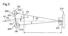
着用者は、その頭部10が実質的にまっすぐであると共に画像センサ210に向かって方向付けられた状態で、着座又は起立することになる(図3を参照されたい)。
The wearer will sit or stand with his
販売員は、更に、画像センサ210の近傍に配置されたターゲット310を見るように着用者1に対して求めることになる(図3を参照されたい)。従って、着用者1の2つの瞳孔21G、21Dの中心と2つの眼20G、20Dの回転の中心OD、OGが、それぞれ、ターゲット310と整列されることになる。
The salesperson will further ask the
図1においては、着用者1によって選択された眼鏡100が、フルリム眼鏡であることが観察され得る(変形形態として、これらは、当然のことながら、ハーフリム又はリムなし眼鏡などの任意のその他のタイプの眼鏡であり得る)。
In FIG. 1, it can be observed that the
この眼鏡100は、2つのディスプレイレンズ150G、150D(着用者の視力の程度に対して調整された眼科レンズによって置換されるように意図されたもの)がその中に装着されている2つのリム111G、111D(又は、レンズ縁)を有する眼鏡フレーム110を有する。
The
2つのリム111G、111Dは、着用者の鼻上に載置される2つの鼻パッドを装備した鼻ブリッジ又はブリッジ113を介して互いに接続されている。又、これらのリムは、それぞれ、着用者1の対応する耳の上部に載置されるテンプル112G、112Dをも装備している。これらのテンプル112G、112Dは、それぞれ、長手方向軸に沿って、その長さの大部分にわたって直線的に延在し、且つ、その端部において湾曲している。
The two
眼鏡フレーム110の2つのリム111G、111Dのそれぞれは、その内側に凹入した状態で、ベゼルと一般に呼ばれる溝を有し、ベゼルには、対応するディスプレイレンズ150G、150Dのエッジ面から突出するベベルが嵌め込まれる。
Each of the two
図2に示されているように、ここでは、中央面P1が、眼鏡フレーム110との関係において定義されており、前記中央面は、2つのリム111G、111Dのベゼルの底部エッジ上のすべての地点に可能な限り近接した状態において延在している。
As shown in FIG. 2, here a central plane P1 is defined in relation to the
この中央面P1は、「装用時前傾角(pantoscopic angle)」と呼ばれる角度だけ、テンプル112G、112Dの長手方向軸を通過する面に対して傾斜している。平均的には、眼鏡フレームの装用時前傾角は、約10度である。
The central plane P1 is inclined with respect to the plane passing through the longitudinal axis of the
図1に示されているように、画像センサ210によって取得された着用者1のそれぞれの画像内において、「ボクシングシステム」に従って定義された2つのボックス151G、151Dにより、眼鏡フレーム110のリム111G、111Dを特徴付けてもよい。
As shown in FIG. 1, in each image of the
これらのボクシングシステムボックス151G、151Dは、眼鏡フレーム110のリム111G、111D(又は、ディスプレイレンズ150G、150D)を取り囲む矩形として定義されており、これらの矩形の2辺は、垂直であり、残りの2辺は、水平である。
These
次いで、それぞれの画像内において、眼鏡フレーム100の観察可能軸A3は、ボクシングシステムボックス151G、151Dの垂直の辺に対して平行であると共にこれらのボックスから等距離に配置された軸であるものとして定義される。
Then, in each image, the observable axis A3 of the
図1に示されているように、フランクフルト面P3は、着用者の眼窩下縁部及びポリオンを通過する面であるものとして、計測位置において、着用者1との関係において定義される(ポリオンは、外耳道の頭蓋内における最高点であり、これは、耳の耳点に対応している)。従って、計測位置において、このフランクフルト面P3は、実質的に水平となる。
As shown in FIG. 1, the Frankfurt plane P3 is defined as a plane passing through the wearer's lower eye socket and the pillion, in relation to the
又、矢状面P2は、フランクフルト面P3に対して、且つ、着用者1の2つの眼20G、20Dの回転の中心OG、ODを通過すると共に着用者の鼻梁を通過する軸に対して、直交する面であるものとして、定義される。従って、計測の際に、この矢状面P2は、実質的に垂直となる。この位置は、着用者1の鼻の位置からではなく、むしろ、着用者1が着用した眼鏡100の位置に応じて、推定されることになる。
The sagittal plane P2 is relative to the Frankfurt plane P3 and to the axis passing through the center of rotation OG and OD of the wearer's two
長手方向軸A1は、矢状面P2内に含まれた状態でフランクフルト面P3に直交すると共に着用者がその頭部を右から左に回転させた際に(即ち、着用者がその頭部を「いいえ」と言うために振った際に)着用者1の頭部10の回転軸に対応するものとして、着用者1の頭部10との関係において、定義される。計測位置において、この長手方向軸A1は、実質的に垂直となる。
The longitudinal axis A1 is orthogonal to the Frankfurt plane P3 while contained within the sagittal plane P2 and when the wearer rotates his head from right to left (ie, the wearer It is defined in relation to the
前部軸A4も、フランクフルト面P3と矢状面P2の間の交差軸として定義される。 The front axis A4 is also defined as the intersection axis between the Frankfurt plane P3 and the sagittal plane P2.
横断軸A5も、長手方向軸A1及び前部軸A4に垂直である軸として定義される。 The transverse axis A5 is also defined as an axis that is perpendicular to the longitudinal axis A1 and the front axis A4.
計測位置において、これらの2つの前部軸及び横断軸A4、A5は、実質的に水平となる。 In the measurement position, these two front axes and transverse axes A4, A5 are substantially horizontal.
図3に示されているように、着用者1の片眼瞳孔間距離EG、EDは、着用者1の2つの眼20G、20Dの回転中心OG、ODから矢状面P2を分離する距離として定義される。
As shown in FIG. 3, the inter-pupil distances EG and ED of the
図1に示されているように、着用者の瞳孔高さHG、HDは、これら自体としては、それぞれの取得された画像内において、(実際には、着用者1の瞳孔21G、21Dの中心と画像内において一致する)着用者1の眼20G、20Dの回転中心OG、ODと対応したボクシングシステムボックス151G、151Dの下部エッジを分離する距離として定義される。
As shown in FIG. 1, the wearer's pupil heights HG, HD are as such in the respective acquired images (actually the centers of the
図3に示されているように、更に、水平面及び垂直面が、画像センサ210との関係において定義され、これらの面の交差部は、画像センサ210の光軸A2と一致している。
Further, as shown in FIG. 3, a horizontal plane and a vertical plane are defined in relation to the
この結果、理想的には、そのフランクフルト面P3が画像センサ210の水平面と一致すると共に、その矢状面P2が画像センサ210の垂直面と一致するように、着用者1の頭部10を配置することが求められる。
As a result, ideally, the
実際には、これらの面の間におけるわずかなずれが一般に観察され、このずれは、計測を損ないがちである。 In practice, slight deviations between these surfaces are generally observed, and this deviation tends to spoil the measurement.
このずれは、3つの角度、即ち、ロール角β、ピッチ角δ、及びヨー角αによって計測されることがあり、これらの角度は、着用者1の頭部10が自由に回転する3つの方式に対応している。
This misalignment may be measured by three angles, namely roll angle β, pitch angle δ, and yaw angle α, which are three ways in which the
即ち、ヨー角αは、(光軸A2と対向する)着用者の頭部10の理想的な位置と着用者の頭部10の実際の位置の間における長手方向軸A1を中心とした着用者1の頭部10の回転角として定義されることになる。このヨー角αは、画像センサ210の水平面内において計測されることになる。
That is, the yaw angle α is the wearer centered on the longitudinal axis A1 between the ideal position of the wearer's head 10 (opposite the optical axis A2) and the actual position of the wearer's
ロール角βは、着用者の頭部10の理想的な位置と着用者の頭部10の実際の位置の間における前部軸A4を中心とした着用者1の頭部10の回転角として定義されることになる。このロール角βは、観察可能軸A3の傾斜に応じて、それぞれの取得された画像上において容易に計測可能となる。
The roll angle β is defined as the rotation angle of the
ピッチ角δは、(光軸A2と対向する)着用者の頭部10の理想的な位置と着用者の頭部10の実際の位置に間における横断軸A5を中心とした着用者1の頭部10の回転角として定義されることになる。このピッチ角δは、画像センサ210の垂直面内において計測されることになる。
The pitch angle δ is the head of the
図4は、本発明による方法の実装を許容すると共に、更に一般的には、ディスプレイレンズ150G、150Dの代わりに着用者1によって選択された眼鏡フレーム110内に装着される眼科レンズを注文するために必要とされるデータの計測及び取得を許容する装置200を示している。
FIG. 4 allows for the implementation of the method according to the invention and more generally for ordering an ophthalmic lens to be mounted in the
この装置は、眼鏡フレームの陳列装置及び計測センタの役割をも同時に果たす眼鏡キオスク200の形態を有する。
This device has the form of a
この目的のために、この装置は、少なくとも1つのマウンティング201と、光源220、230、240と、画像センサ210と、処理ユニット250と、を有する。
For this purpose, the device comprises at least one mounting 201,
好ましくは、光源220、230、240は、赤外線を放出し、且つ、画像センサ210は、赤外線画像をキャプチャする。
Preferably, the
ここで使用されることになる赤外線の領域は、近赤外線であり、その波長は、780〜1400nmに含まれる。 The infrared region to be used here is near infrared, and its wavelength is included in 780 to 1400 nm.
具体的には、赤外光の使用は、いくつかの利点を有する。赤外光を使用すれば、特に、眼鏡100のディスプレイレンズ150G、150D上において反射する外部又は内部光の結果としてもたらされる寄生反射を回避することができる。又、赤外光を使用すれば、着用者1が計測の際に眩しさを感じることを防止することもできる。最後に、赤外光を使用すれば、ディスプレイレンズ150G、150Dが着色されている際にも、画像センサ210によって取得された画像内の着用者1の眼を観察することができる。
Specifically, the use of infrared light has several advantages. Infrared light can be used to avoid, in particular, parasitic reflections resulting from external or internal light reflecting on the
眼鏡キオスクが立っている床に対して固定された状態で画像センサ及び光源が保持されるように、マウンティングを単一の部品から構成することができよう。この場合には、その頭部が画像センサの視野内に配置されるように着用者を配置できるように、高さ調節可能な椅子を提供することが必要となろう。 The mounting could be constructed from a single piece so that the image sensor and light source are held fixed against the floor on which the spectacle kiosk stands. In this case, it would be necessary to provide a height adjustable chair so that the wearer can be positioned so that its head is positioned within the field of view of the image sensor.
対照的に、図4に示されているキオスク200の実施形態においては、マウンティング201は、地面に配置される基部202と、垂直軸A8に沿って基部202に対して平行運動するように取り付けられると共に光源220、230、240及び画像センサ210を保持するスライド205と、を有する。
In contrast, in the embodiment of the
従って、画像センサ210の位置は、着用者1のサイズに応じて、高さ調節可能である。
Accordingly, the height of the position of the
基部202は、更に正確には、垂直軸A8に沿って細長くなっており、且つ、正方形の水平方向断面を有する中空平行六面体の形状を有する。
More precisely, the
この基部202は、地面上に配置された壁によって閉鎖された下端部と、スライド205が挿入される開放した上端部と、を有する。
The
この目的のために、このスライド205は、中空平行六面体の形状を有し、水平方向断面の外側寸法は、基部202の内側寸法に等しく、これにより、スライドが基部202内において摺動できるようになっている。
For this purpose, the
このスライド205は、基部202の内部に開放した下端部と、フラットな壁によって閉鎖された上端部と、を有する。
The
スライド205は、スライド205を2つの(高い及び低い)停止位置の間において垂直軸A8に沿って平行運動方式でガイドできるように、基部202の両側に生成された2つの垂直方向の長い孔203に挿入される2つの突出ピン204を両側に有する。
The
更には、スライド205が基部202内において望ましい高さに上昇及び降下できるようにする動力化された作動手段(図示せず)が設けられる。
In addition, motorized actuating means (not shown) are provided that allow the
基部202内におけるスライド205の高さを判定するための手段(例えば、ラックと関連するエンコーダホイール)も設けられる(図示せず)。
Means (eg, an encoder wheel associated with the rack) for determining the height of the
マウンティング200は、着用者1に対向する前面を有する2つの横方向ウィング206、207を更に有する。
Mounting 200 further includes two
これら2つの横方向ウィング206、207は、垂直壁によって形成されおり、これらの垂直壁は、前方にわずかに湾曲すると共に基部202の両側においてヒンジで取り付けられており、基部の両側には、垂直方向の長い孔203が設けられている。
These two
更に、これらのウィング206、207の前面は、フック(図示せず)を装備しており、このフックには、着用者によって選択される眼鏡フレームが載置される。
Furthermore, the front surface of these
図4においては、スライド205が、計測位置において着用者1の頭部10を照射するのに適した少なくとも2つの(ここでは、3つの)赤外光源220、230、240を保持していることが観察されよう。
In FIG. 4, the
これらの光源220、230、240は、好ましくは、画像センサ210の垂直面内において、画像センサのいずれかの側に分散されている。
These
これらの3つの光源220、230、240は、ここでは、スライド205に対して平行移動しない状態となるように取り付けられており、且つ、複数の発光ダイオード(LED)から形成されている。
Here, these three
主光源と呼ばれる光源のうちの1つ220は、画像センサ210から小さな距離だけ(即ち、ここでは、画像センサから10cm未満だけ)離れたところに配置されている。これは、円として分散された複数のLEDから構成されている。これらのLEDは、スライド205に対して直接固定されている。図4に示されているように、この主光源220は、画像センサ210の上方に配置されている。
One of the
2次光源と呼ばれる2つのその他の光源230、240は、画像センサ210の下方において、上下に配置されている。これらは、それぞれ、主光源220内において使用されているLEDの数に等しい数のLEDから構成されており、これらのLEDは、2つの同心円として分散されている。これらは、主光源220によって放出される光の強度よりも小さな強度の光を放出する。2次光源230、240によって放出される光強度は、主光源220によって放出される強度と同様の方式で調節可能である。
Two other
これら2つの2次光源230、240は、2つの別個の水平回転軸A6、A7を中心としてスライド205に対して回転移動できるように取り付けられた支持部231、241に固定されている。この可動性により、これらの2次光源230、240を着用者1の頭部10に向って手動で方向付けすることができる。
These two secondary
3つの光源220、230、240は、更に正確には、着用者1が着用した眼鏡100のディスプレイレンズ150G、150D上に別個の反射を形成するように設計されている。
More precisely, the three
従って、すべての光源220、230、240が2つのディスプレイレンズ150G、150D上において反射された際に、画像センサ210は、6つのガラス反射を観察することになる。
Therefore, when all the
3つの光源220、230、240を使用することにより、画像センサ201は、着用者1の頭部のピッチ角δとは無関係に、これらの反射のうちの少なくともいくつかを観察することができる。具体的には、着用者1がその頭部を前方に傾斜させた際には、画像センサ210によって観察される反射は、ずり上がり、且つ、最終的には、ディスプレイレンズ150G、150Dから離脱することになることを理解されたい。
By using three
更に、3つの光源220、230、240は、着用者1のそれぞれの眼の上部に、角膜反射と呼ばれる単一の反射を形成する。
Furthermore, the three
図6は、光源220、230、240のうちの2つのみが、2つのディスプレイレンズ150G、150D上において反射している状況を示している。即ち、主光源220及び2次光源のうちの1つ230によって生成された4つのガラス反射160G、160D、161G、161Dと、2つの角膜反射162G、162Dと、が2つのディスプレイレンズ150G、150D上において観察される。対照的に、第3光源240は、ディスプレイレンズ150G、150D上に反射を生成するには、着用者1の頭部のピッチ角δに対して低く過ぎる。
FIG. 6 shows a situation where only two of the
当然のことながら、一変形として、キオスクが、1つの単一の赤外光源のみを有するようにすることもできよう。 Of course, as a variant, the kiosk could have only one single infrared light source.
この1つの赤外光源は、画像センサに対して予め設定された位置において固定された状態で取り付けることができよう。この場合には、検出可能な角膜反射を生成するべく、極めて大きなサイズの光源を使用することが好ましいであろう。更には、この光源は、フレーム平均装用時前傾角を考慮した場合に、着用者1の頭部10が理想的に配置された際に(フランクフルト面P3が画像センサ210の水平面と一致し、且つ、矢状面P2が画像センサ210の垂直面と一致している際に)、生成される2つのガラス反射が、実質的に、ディスプレイレンズ150G、150Dの真ん中に(即ち、フレームの2つのボクシングシステムボックスの中心を通過する軸上に)配置されるように、配置しなければならないであろう。
This one infrared light source could be mounted in a fixed state with respect to the image sensor at a preset position. In this case, it would be preferable to use a very large size light source to produce a detectable corneal reflection. Furthermore, this light source is arranged such that when the
従って、画像センサがディスプレイレンズ上においてこの光源の反射を観察できるように着用者の頭部のピッチ角が小さなものに留まっていることを計測の際にチェックすることが推奨されよう。 Therefore, it would be recommended to check during measurement that the pitch angle of the wearer's head remains small so that the image sensor can observe the reflection of this light source on the display lens.
別の変形形態によれば、場合により、この単一の光源は、着用者の頭部のピッチ角を補償するために、画像センサに対して垂直に平行移動可能となるように取り付けられることになろう。 According to another variant, in some cases, this single light source may be mounted so that it can be translated vertically relative to the image sensor to compensate for the pitch angle of the wearer's head. Become.
図4に示されているように、キオスク200は、ここでは、水平方向の光軸A2を有する1つの単一の画像センサ210を有する。
As shown in FIG. 4, the
この場合には、この画像センサは、近赤外線において且つ可視光において画像を取得するのに適したビデオカメラ210によって形成されている。
In this case, the image sensor is formed by a
この場合には、このビデオカメラは、FCB−EX490という型名のSony(登録商標)製ビデオカメラである。このビデオカメラは、ビデオカメラ210が可視領域において画像(以下、「可視画像」と呼ぶ)を取得できるように赤外光をフィルタリングする通常位置と、赤外光がセンサまで通過できるようにすることにより、赤外線領域において画像(以下、「赤外線画像」と呼ぶ)を取得できるようにする退却位置と、の間において切替可能な赤外線フィルタを装備している。
In this case, this video camera is a Sony (registered trademark) video camera having a model name of FCB-EX490. This video camera has a normal position for filtering infrared light so that the
従って、このビデオカメラは、着用者の赤外線画像を取得するのに適しており、この赤外線画像には、ガラス反射及び角膜反射が明瞭に表れており、且つ、この着用者の可視画像により、着用者は、選択された眼鏡100が着用者に似合っていることをチェックすることができる。
Therefore, this video camera is suitable for acquiring an infrared image of the wearer. The infrared image clearly shows the glass reflection and the corneal reflection. The person can check that the selected
当然のことながら、一変形形態として、場合により、1つのビデオカメラではなく、赤外線画像を取得するのに適したものと、可視画像を取得するのに適したもう1つのものという2つの別個のビデオカメラが設けられることになる。 Of course, as a variant, in some cases, two separate, one suitable for acquiring an infrared image and another suitable for acquiring a visible image, rather than one video camera. A video camera will be provided.
ここで、スライド205の前面壁は、マジックミラーによって閉鎖されたウィンドウを含んでおり、この背後に、ビデオカメラ210が配置されている。従って、ビデオカメラ210は、キオスク200の外部からは、観察できないが、ビデオカメラは、キオスク200の前面に位置した人物の画像を取得するのに適した状態に留まっている。
Here, the front wall of the
この場合に、ビデオカメラ210は、その対物レンズがこのマジックミラーの背面と接触した状態で又はその近傍に配置されるように、キオスク200内に設置されている。
In this case, the
更に、カメラ210の対物レンズは、寄生反射が取得された画像内に現れることを防止する不透明な側壁によって取り囲まれている。
In addition, the objective lens of the
この例においては、ビデオカメラの全体が、ここでは、対物レンズが出現する開口部によって前方に開放した不透明なハウジング内に収容されており、このハウジングは、マジックミラーの背面との接触状態において配置されている。 In this example, the entire video camera is here housed in an opaque housing opened forward by an opening through which the objective lens appears, which housing is arranged in contact with the back of the magic mirror. Has been.
更には、眼鏡キオスク200は、計測位置において着用者1によって観察されるように、ビデオカメラ210の対物レンズの隣に、且つ、ビデオカメラ210の対物レンズから小さな距離だけ離れるように、配置された少なくとも1つのターゲット310を有する。
Furthermore, the
ここで、このターゲット310は、ビデオカメラ210の対物レンズと2次光源230、240の間においてスライド205の壁に生成されたウィンドウ208を有し、このウィンドウ208を通じて、LEDが観察されることになる。実際には、このLEDは、ここでは、マウンティング200の基部202内に配置されており、且つ、ミラーの組により、ウィンドウ208に向って反射されている。
Here, the
このターゲット310により、計測の際に、着用者1の凝視をビデオカメラ210の対物レンズに向かって引き付けることができる。
With this
ビデオカメラ210の水平面内において、マウンティング200のウィング206、207のうちのそれぞれのウィングの外部エッジ上に配置された2つの更なるターゲット320、330も設けられている。
In the horizontal plane of the
本明細書の残りの部分において更に詳述されるように、これらの追加のターゲット320、330により、この着用者1が、ある程度その頭部10又はその眼20G、20Dを移動させることによってその凝視を回転させる傾向を有するかどうかを判定するために、着用者1の凝視をキオスク200の一側部に向って、且つ、次いで、他側部に向かって、順番に引き付けることができるようになる。
As will be described in further detail in the remainder of this specification, these
更には、ビデオカメラ210によって取得された可視画像が十分に露光するように着用者1の頭部10を照射する、マウンティング200の2つのウィング206、207の上部エッジにおいてそれぞれ位置決めされた、2つの蛍光管260も設けられている。
Furthermore, two positioned respectively at the upper edges of the two
これらの2つのウィング206のうちの一方の内部には、取得された可視画像を表示する手段270及び印刷する手段280が設けられている。
Inside one of these two
ここで、表示手段は、計測位置において着用者1にとって可視状態となるように、ウィング206の前面に固定されたタッチスクリーン270から構成されている。
Here, the display means includes a
印刷手段は、眼科レンズ用の注文データを要約するシートを印刷するように設計されており、このシート上には、着用者の写真が表示される。 The printing means is designed to print a sheet summarizing order data for the ophthalmic lens, on which a photograph of the wearer is displayed.
更には、着用者1の処方箋を読み取る手段が設けられている。
Furthermore, a means for reading the prescription of the
この場合には、印刷手段と読取り手段は、1つにマージされており、且つ、マウンティング200のウィング206の前面に凹入した状態で設けられたハウジング内に配置された単一の多機能カラープリンタ280から構成されている。
In this case, the printing means and the reading means are merged into one, and a single multi-function color disposed in a housing provided recessed in the front face of the
当然のことながら、一変形形態として、要約シートを印刷するものと、処方箋を読み取るもう1つのものという2つの別個の装置を提供することもできよう。 Of course, as a variant, it would be possible to provide two separate devices, one that prints the summary sheet and another that reads the prescription.
最後に、2つのウィング207のうちの他方の上部には、眼鏡100の少なくとも1つの寸法を取得する手段が設けられている。具体的には、ビデオカメラ210によって取得された画像は、着用者1の眼鏡100の寸法の判定を許容していない。従って、取得された画像をスケーリングする必要がある。
Finally, on the other upper part of the two
上述の取得手段290は、様々な形態をとってもよい。 The acquisition means 290 described above may take various forms.
好ましくは、これらは、データベースに接続されたバーコード読取機290を有しており、データベースは、そのそれぞれの記録が眼鏡フレームモデルと関連付けられており、且つ、この眼鏡フレームモデルと関係する識別子及びデータを有する。
Preferably, they have a
この例においては、それぞれの記録の識別子は、眼鏡フレームモデルに割り当てられたバーコードの数字によって形成されている。 In this example, the identifier of each record is formed by a bar code number assigned to the spectacle frame model.
それぞれの記録内に記憶されているデータは、この場合には、
− 2つのテンプル112D、112Gの間において計測された対象モデルの眼鏡フレームの合計幅と、
− これらの眼鏡フレームのリムのボクシングシステムボックス151G、151Dの高さ及び長さの比率と、
− これら2つのボクシングシステムボックス151G、151Dを分離している距離と、
を含む。
The data stored in each record is in this case
The total width of the spectacle frame of the target model measured between the two
-The ratio of the height and length of the
-The distance separating these two
including.
当然のことながら、データベースのそれぞれの記録内に記録されているデータは、相対的に少ない数の要素(例えば、眼鏡フレームの合計幅のみ)又は相対的に多くの数の要素(例えば、リムの正確な形状、眼鏡フレームの材料、眼鏡フレームの装用時前傾角及び顔形角など)を含むことができよう。 Of course, the data recorded in each record of the database can be a relatively small number of elements (eg only the total width of the spectacle frame) or a relatively large number of elements (eg Exact shape, eyeglass frame material, spectacle frame tilt angle, face shape angle, etc.).
一変形形態として、これらの取得手段は、販売員が、
− 販売員が定規を使用して予め計測しておいた選択された眼鏡フレーム110の幅を入力し、且つ、
− 取得された画像上において、販売員がフレームの幅を計測した2点において2つのカーソルを位置決めする、
ことができるようにする単純なキーボード(物理的なキーボード又はタッチスクリーン上に表示されたキーボード)のみを有することもできよう。
As a variant, these acquisition means are used by the salesperson
-Enter the width of the selected
-On the acquired image, position the two cursors at the two points where the salesperson measured the width of the frame;
It would also be possible to have only a simple keyboard (a physical keyboard or a keyboard displayed on a touch screen) that makes it possible.
更に別の変形形態として、これらの取得手段は、ビデオカメラによって取得されたそれぞれの画像内において、その寸法が既知であり、これにより、この画像のスケーリングを可能にする基準を得るべく、(クリップファスナ、接着接合、又は任意のその他の手段によって)選択された眼鏡フレームに装着される既知の寸法の単純なゲージのみを有することもできよう。 As yet another variant, these acquisition means are known in their dimensions within each image acquired by the video camera, thereby obtaining a reference that allows scaling of this image (clip It would also be possible to have only a simple gauge of known dimensions that is attached to the selected spectacle frame (by fastener, adhesive bonding, or any other means).
図4に示されているように、眼鏡キオスク200の処理ユニット250の部分は、マウンティング200の基部202内に収容されている。これは、キオスク200の様々な電子コンポーネントを制御するように、且つ、ビデオカメラ210によって取得された画像を処理するように、設計されている。
As shown in FIG. 4, the portion of the
この目的のために、この処理ユニット250は、プロセッサ(CPU)と、ランダムアクセスメモリ(RAM)と、読出し専用メモリ(ROM)と、アナログ−デジタル(A/D)コンバータと、様々な入力、出力、及び通信インターフェイスと、を有する。
For this purpose, the
その入力インターフェイスにより、処理ユニット250は、ビデオカメラ210によって取得される画像、前記判定手段によって計測された基部202内のスライド205の高さ、及びバーコード読取機290によって読み取られた選択された眼鏡フレームのバーコードの数字を受け取るのに適している。
With its input interface, the
従って、処理ユニット250は、そのランダムアクセスメモリ内に、これらの様々なデータを連続的に保存する。
Accordingly, the
その読出し専用メモリ内に保存されているソフトウェアプログラムにより、処理ユニット250は、本記載の残りの部分に記述されている方法の全体を実装するのに適している。従って、この処理ユニットは、例えば、望ましい高さにおいてスライドを位置決めするべく、スイング205を作動させる手段を制御するための信号を生成し、且つ、眼科レンズを注文するためのデータを含む信号を伝達するのに適している。
With the software program stored in its read-only memory, the
その出力インターフェイスにより、処理ユニット250は、これらの出力信号をキオスク200の様々な電子コンポーネントに、特に、ビデオカメラ210に、光源220、230、240に、タッチスクリーン270に、多機能プリンタ280に、ターゲット310、320、330に、且つ、スライド205を作動させる手段に、送信するのに適している。
With its output interface, the
その通信インターフェイスにより、処理ユニット250は、通信信号を眼科レンズを製造するセンタに送信するのに適している。最後に、キオスク200の電源を投入するスイッチが設けられている。
With its communication interface, the
着用者1の到着の前に、販売員は、キオスク200の電源を投入するが、これは、この目的のために設けられたスイッチを使用することによって実行される。
Prior to arrival of the
電源投入の際に、制御ユニットは、キオスク200のマウンティング201のウィング206、207の陳列装置上の眼鏡を照射するように、蛍光管260の電源を制御する。
When the power is turned on, the control unit controls the power supply of the
3つの赤外光源220、230、240は、消灯された状態に留まる。
The three infrared
次に、人物が現れた際に、人物は、画面上の指示メッセージを読み取った後に、キオスク200のマウンティング201のウィング206、207の陳列装置上のすべての眼鏡から1つの眼鏡100を選択する。図面に示されている例においては、選択された眼鏡は、フルリム眼鏡である。次に、画面上に表示された指示メッセージに従って、人物は、プロトコルの残りの部分のために、販売員を呼び出す。
Next, when a person appears, after reading the instruction message on the screen, the person selects one
次いで、選択された眼鏡フレーム110の特徴的な寸法を判定するための作業が実行される。
Next, an operation for determining a characteristic dimension of the selected
上述のように、この作業は、特に、取得された画像のスケーリングを可能にするべく、実行される。 As mentioned above, this work is performed in particular to allow scaling of the acquired image.
この作業の際に、販売員は、バーコード読取機290の前面において、選択された眼鏡フレーム110のバーコードを通過させる。次いで、処理ユニット250は、バーコードの数字により、この眼鏡フレーム110に対応する記録についてデータベース記録をサーチし、次いで、処理ユニット250は、眼鏡フレーム110の合計幅、この眼鏡フレーム110のリム111D、111Gのボクシングシステムボックス151G、151Dの高さと幅の比率、及びこれらの2つのボクシングシステムボックス151G、151Dを分離している距離からなるデータを取得し、且つ、その読出し専用メモリ内に保存する。
During this operation, the salesperson passes the barcode of the selected
当然のことながら、上述のように、このバーコード読取作業は、例えば、販売員が、定規を使用して眼鏡フレームの合計幅を計測するステップと、タッチスクリーン上に表示された仮想的なキーボード上において前記幅を入力するステップと、取得された画像上において、販売員がフレームの幅を計測した2つの点において2つのカーソルを位置決めするステップと、からなる相対的に単純な作業によって置換することができよう(この2つの点を位置決めする作業は、場合により、一変形形態として、自動的に実行される)。 Of course, as described above, this bar code reading operation includes, for example, a step in which the salesperson measures the total width of the spectacle frame using a ruler, and a virtual keyboard displayed on the touch screen. Substituting by a relatively simple task comprising: inputting the width above; and positioning the two cursors at two points where the salesperson has measured the width of the frame on the acquired image. (The task of positioning the two points is sometimes performed automatically as a variant).
次いで、着用者が検眼師から予め入手しておいた着用者の処方箋を取得する作業が行われる。 Next, the wearer acquires the wearer's prescription that the wearer previously obtained from the optometrist.
これらの処方箋は、一般に、処方箋フォーム上に記述されており、且つ、具体的には、レンズのタイプ(単焦点、二重焦点、多重焦点、着色レンズなど)と、レンズが着用者の視覚的な欠陥を矯正しなければならない屈折力(即ち、その球面、円筒、及びプリズムジオプトリ及びその円筒軸)と、を含む。これらは、当然のことながら、二重焦点又は多重焦点レンズの場合における累進(adddition)などのその他の情報を含んでもよい。 These prescriptions are generally described on a prescription form, and specifically, the type of lens (single focus, bifocal, multifocal, colored lens, etc.) and the lens is the wearer's visual Refractive power (ie, its spherical surface, cylinder, and prism diopter and its cylinder axis) that must be corrected. These may of course include other information such as additions in the case of bifocal or multifocal lenses.
次いで、この作業において、販売員は、処方箋フォームを取得し、且つ、処理ユニット250がこの処方箋フォームの読み取られた画像をその読出し専用メモリ内に保存するように、多機能プリンタ280を使用して処方箋フォームを読み取る。
In this operation, the salesperson then obtains the prescription form and uses the
又、販売員は、着用者が自身の眼科レンズ上において所望する処理(反射防止や疎水性など)を選択し、この情報を、タッチスクリーン270上において、処理ユニット250によってこの目的のために表示されたフィールド内に入力するように、着用者に求めてもよい。
The salesperson also selects the treatment that the wearer wants on his ophthalmic lens (such as anti-reflection or hydrophobicity) and displays this information on the
この情報が取得されると、処理ユニット250は、第1ターゲット310の電源を投入する。
When this information is acquired, the
又、処理ユニットは、タッチスクリーン270上に、
− 計測作業を開始してもよいことを通知するメッセージと、
− ビデオカメラ210によって「リアルタイムで」取得された画像と、
− スライド205を上又は下に移動させるための、一方は、上を指し、他方は、下を指している反対に方向付けされた2つの矢印と、
を表示する。
The processing unit is also on the
-A message notifying that the measurement work may start;
-Images acquired "in real time" by the
-Two oppositely oriented arrows pointing to the top and the other pointing down for moving the
Is displayed.
次いで、販売員は、まず、着用者1に対して、その眼鏡を着用し、且つ、後続する試験のすべてにおいてその眼鏡を着用したままでいるように促す。
The sales clerk then prompts
本記載の残りの部分において詳述するように、これらの試験においては、次いで、キオスク200は、着用者1の片眼瞳孔間距離EG、ED及び瞳孔高さHG、HDと、眼鏡フレーム110と着用者1のそれぞれの眼の間の距離VG、VD(図8)及びその凝視の移動行動などのような高度な個人化パラメータと、を判定することを許容することになる。
As will be described in detail in the remainder of this description, in these tests, the
これを実行するために、販売員は、着用者1に対して、計測位置においてキオスク200に対向した状態となり、且つ、そのフランクフルト面P3が実質的に水平になると共にその矢状面P2が実質的に垂直になるように、その頭をまっすぐに維持したまま第1ターゲット310を見るように求める。
In order to do this, the salesperson faces the
この場合に、着用者1は、自身がキオスク200のマウンティング201のスライド205と対向した状態において起立した状態となるように促される。
In this case, the
次いで、販売員は、スライド205の位置を着用者1の高さに適した高さに調節する。この目的のために、販売員は、着用者1の顔のすべてがビデオカメラ210によって取得されると共にタッチスクリーン270上に表示される画像内に現れるような高さに位置する時点まで、タッチスクリーン270上に表示された矢印を使用し、スライド205の上向き又は下向きの動きを制御する。
Next, the salesperson adjusts the position of the
この結果、この位置において、着用者1の顔の全体がビデオカメラ210の視野に収容される。
As a result, the entire face of the
このビデオカメラ210を着用者1の頭部10の高さに位置決めする作業は、当然のことながら、別の方法によって実行することもできよう。
The operation of positioning the
即ち、この作業は、処理ユニットによって自動的に実行することも可能であり、処理ユニットが、ビデオカメラによって取得された画像内において眼鏡フレームを認識するようにビデオカメラによって取得された画像を処理し、且つ、相応してビデオカメラによって取得された画像の中心において眼鏡フレームを見出すような高さにスイングを制御することになろう。 That is, this operation can also be performed automatically by the processing unit, which processes the image acquired by the video camera so as to recognize the spectacle frame in the image acquired by the video camera. And correspondingly, the swing will be controlled to such a height that the glasses frame is found in the center of the image acquired by the video camera.
一変形形態として、画像センサが地面に対して移動自在に取り付けられていない場合には、この位置決め作業は、場合により、その高さが予め調節されている椅子に着座するように着用者に対して求めることにより、実行されることになる。 As a variant, if the image sensor is not movably mounted with respect to the ground, this positioning operation may be performed on the wearer, possibly sitting in a chair whose height is adjusted in advance. Will be executed.
このビデオカメラ210に対して着用者1を位置決めする作業が実行されると、販売員は、タッチスクリーン270上に表示された特別なボタンを押下することにより、計測値の取得を開始する。
When the operation of positioning the
次いで、制御ユニット250は、3つの赤外光源220、230、240を公称強度に点灯させる。
The
当然のことながら、制御ユニットは、外部光が計測を妨げることを防止するべく、外部光の強度に応じて、この強度を調整することができよう。但し、赤外光を使用することにより、公称強度でほぼ十分な程度にまで、これらの妨害を制限することができる。 Of course, the control unit could adjust this intensity according to the intensity of the external light to prevent the external light from interfering with the measurement. However, the use of infrared light can limit these disturbances to an almost sufficient extent at nominal intensity.
この結果、3つの別個の光源220、230、240を使用することにより、当然のことながら、着用者1がその頭部を後ろに回転させない限り、眼鏡100のそれぞれのディスプレイレンズ150G、150D上における少なくとも1つの反射の存在が保証される。
As a result, by using three separate
キオスクが、ビデオカメラに対して高さにおいて移動可能な1つの光源しか有していない変形形態においては、ビデオカメラと対向するように着用者を位置決めする作業は、光源を位置決めするための自動的な作業に準じたものとなろう。この作業においては、処理ユニットは、光源の高さを変化させることになり、且つ、ガラス反射がディスプレイレンズ上においてセンタリングされる高さにおいて光源を固定するために、ビデオカメラによって取得された画像を処理することになろう。 In variants where the kiosk has only one light source that can move in height relative to the video camera, the task of positioning the wearer so as to face the video camera is automatic for positioning the light source. It will be according to the work. In this work, the processing unit will change the height of the light source, and the image acquired by the video camera to fix the light source at a height where the glass reflection is centered on the display lens. Will be processed.
いずれの場合にも、次いで、販売員は、(「いいえ」と言うようにその頭部を振るように)その頭部10を長手方向軸A1を中心として右から左に且つ左から右に回転させるように着用者1に対して求める。
In either case, the salesperson then rotates the
着用者は、この移動が低速において(1秒よりも長い期間にわたって)小さな振幅(約10度)によって実行されなければならない旨の指示を受ける。 The wearer is instructed that this movement must be performed at low speed (over a period longer than 1 second) with a small amplitude (about 10 degrees).
一変形として、ビデオカメラ及び光源が着用者の頭部の長手方向軸を中心として一緒に回転するように、ビデオカメラ及び光源を移動自在に取り付けることもできよう。この結果、着用者は、その頭部を移動させる必要がなくなろう。 As a variation, the video camera and light source could be movably mounted so that the video camera and light source rotate together about the longitudinal axis of the wearer's head. As a result, the wearer will not have to move his head.
次に、着用者1が要求された方式でその頭部の回転を開始した際に、販売員は、計測を開始するためのボタンを押下するが、前記ボタンは、タッチスクリーン270上に表示されている。
Next, when the
次いで、ビデオカメラは、複数の赤外線画像を取得し、これらの画像の上には、着用者1の頭部10とその眼鏡100が表れている。
Next, the video camera acquires a plurality of infrared images, and the
取得された画像は、まず、処理ユニット250のランダムアクセスメモリ内に保存される。次いで、使用可能であると判定された特定の画像が、処理ユニット250によって選択され、且つ、その読出し専用メモリ内に保存される。取得された画像の選択は、以下の方法によって実行される。
The acquired image is first stored in the random access memory of the
取得された画像は、複数のガラス反射(最大で6つ)を収容することになり、様々な基準に基づいて、特に、その
− 形状(幅、高さ、幅/高さ比)と、
− 強度(輝度)と、
に基づいて、それぞれのガラス反射160G、160D、161G、161Dを採点する。
The acquired image will contain multiple glass reflections (up to 6) and, based on various criteria, in particular its shape (width, height, width / height ratio),
− Intensity (luminance);
Based on the above, each
更には、その他の基準に従って、特に、
− 反射の間の距離と、
− ボクシングシステムボックスの水平方向軸との関係におけるその水平性と、
− 反射のエリアの比較と、
に従って、反射のそれぞれのペア(所与の光源によって生成され、且つ、それぞれ、2つのディスプレイレンズによって反射されたもの)を採点する。
Furthermore, according to other criteria, in particular
-The distance between reflections;
-Its horizontality in relation to the horizontal axis of the boxing system box;
-A comparison of areas of reflection;
And scoring each pair of reflections (generated by a given light source and reflected by two display lenses, respectively).
ここで、それぞれの基準に由来する採点は、2値ではない。 Here, the scoring derived from each criterion is not binary.
例えば、採点は、
− 基準が、(処理ユニット250の読出し専用メモリ内において予め設定及び保存された)その公称値の90%〜110%に含まれる場合には、採点が1に等しく、
− 基準がその公称値の120%超であるか又はその70%未満である場合には、採点が0に等しく、且つ、
− 採点が、70%〜90%の間において、且つ、110%と120%の間において、線形で変化するように、
0と1の間において連続的に変化するようにしてもよい。
For example, scoring is
If the criterion is included between 90% and 110% of its nominal value (preset and stored in the read-only memory of the processing unit 250), the scoring is equal to 1;
-If the criterion is greater than 120% or less than 70% of its nominal value, the score is equal to 0, and
-The scoring varies linearly between 70% and 90% and between 110% and 120%,
It may be changed continuously between 0 and 1.
又、ガラス反射に対して適用される基準は、必要な変更を加えて、角膜反射162G、162Dに適用してもよい。角膜反射に適用される更なる基準は、観察可能軸A3からそれぞれの角膜反射を分離している距離となる。
Also, the criteria applied to the glass reflections may be applied to the
従って、画像が選択される可能性は、様々な上述の基準に由来する採点の積に伴って増大する。 Thus, the likelihood that an image will be selected increases with the product of scoring from the various above criteria.
例えば、選択される画像が、その採点の積が予め設定された閾値を上回っているものとなるようにしてもよい。 For example, the selected image may be such that the product of scoring exceeds a preset threshold value.
一変形として、選択される画像が、その採点の積が最大であるものとなるようにしてもよい。 As a variation, the selected image may have the maximum score product.
更には、画像に由来する採点のうちの1つが別の予め設定された閾値を下回っている場合に、その画像が自動的に拒絶されるようにしてもよい。 Furthermore, the image may be automatically rejected if one of the scoring originating from the image is below another preset threshold.
従って、取得された画像内において、着用者1が、その頭部を過大なヨー角αだけ回転させており、且つ、ガラス反射がもはやディスプレイレンズ150G、150Dのアウトライン内に存在していない場合には、この画像は、自動的に拒絶される。
Accordingly, in the acquired image, when the
更には、取得された画像内において、着用者1がその頭部を過大なロール角βだけ傾斜させており、且つ、所与の光源によって生成されたガラス反射が2つのディスプレイレンズ上において高さにおいてオフセットされている場合に、オフセットが真に過大である場合には、この画像は、場合により、拒絶されることになり、或いは、その他の基準に由来する採点が高い場合には、この画像は、場合により、選択されることになる。
Furthermore, in the acquired image, the
この結果、処理ユニット250は、方法の残りの部分において使用可能である限られた数の赤外線画像を得る。
As a result, the
本記載においては、わかりやすくするために、処理ユニット250は、図5〜図7に示されている3つの赤外線画像301、302、303のみを選択したものと見なすこととする。
In this description, for the sake of clarity, it is assumed that the
好ましくは、処理ユニットは、少なくとも10個の異なる画像を選択した際に、画像の取得を停止することになる。 Preferably, the processing unit will stop acquiring images when at least 10 different images are selected.
次に、処理ユニット250は、着用者1の顔の可視画像を保存するために、ビデオカメラ210の赤外線フィルタを切り替える。
Next, the
処理ユニットは、同時に、赤外光源220、230、240を消灯し、且つ、タッチスクリーン270上にメッセージを表示することにより、着用者がその頭部の回転を停止できることを着用者に対して通知する。
At the same time, the processing unit turns off the infrared
従って、このメッセージは、処理ユニット250が予め設定された数の、ここでは、10に等しい数の、画像を選択した後に、表示される。
This message is therefore displayed after the
一変形として、十分に大きな数の使用可能な画像の取得を可能にするのに十分に長いと考えられる、例えば、10秒に等しいものなどの、予め設定された長さの時間の後に、このメッセージを表示するようにすることもできよう。この場合には、画像は、場合により、すべての画像が取得された後に、後から選択することができよう。 As a variant, after a pre-set length of time, such as one equal to 10 seconds, which is considered long enough to allow acquisition of a sufficiently large number of usable images, this A message could be displayed. In this case, the image could possibly be selected later after all the images have been acquired.
画像301、302、303が選択されると、処理ユニット250は、これらの画像のそれぞれにおいて、着用者1の頭部10のヨー角αを算出する。
When the
このヨー角αは、それぞれの画像301、302、303内において、着用者1の頭部の矢状面P2に対してガラス反射160D、160G、161D、161Gを見出すことにより、算出される。
The yaw angle α is calculated by finding the
ここで、このヨー角αは、更に正確には、眼鏡フレームの観察可能軸A3に対してガラス反射160D、160G、161D、161Gを見出すことにより、判定される(その理由は、その位置が、眼鏡フレーム110の中央面P1と矢状面P2の交差部に実質的に対応しているからである)。
Here, this yaw angle α is more precisely determined by finding the
眼鏡フレーム110の観察可能軸A3の位置は、
− それぞれの画像301、302、303内において、眼鏡フレーム110を、且つ、特に、この眼鏡フレームのリム111D、111Gを、見出すステップと、
− それぞれの画像301、302、303上において、ボクシングシステムボックス151G、151Dを位置決めするステップと、
− 観察可能軸A3に実際には対応しているこれら2つのボクシングシステムボックスの間を通過する軸の位置を判定するステップと、
からなる3つのステップによって得られる。
The position of the observable axis A3 of the
-Finding in each
-Positioning the
-Determining the position of the axis passing between these two boxing system boxes that actually corresponds to the observable axis A3;
Is obtained by three steps.
ここで、赤外光を使用することにより、そのアウトラインが着用者1の顔のアウトラインから明瞭に突き出ている眼鏡フレーム110を見出すことが容易になる。
Here, by using infrared light, it is easy to find the
この結果、それぞれの画像301、302、303内の着用者1の頭部10のヨー角αは、観察可能軸A3からガラス反射160D、160G、161D、161Gを分離している距離の関数として算出される。
As a result, the yaw angle α of the
通常、図5〜図7に明瞭に示されているように、処理ユニット250は、それぞれの画像301、302、303内において、2つの最大ガラス反射160G、160Dの中心から観察可能な軸A3を分離している距離XD301、XG301、XD302、XG302、XD303、XG303を判定する(主光源によって生成されるガラス反射が、取得された画像内に現われていない場合にのみ、2次光源によって生成されたガラス反射が使用される)。
Typically, as clearly shown in FIGS. 5-7, the
次いで、それぞれの画像301、302、303内の着用者1の頭部10のヨー角αiが、次の方式で判定される。
αi=k.(XGi-XDi)/(XGi+XDi)
ここで、iは、301〜303の範囲である。
Next, the yaw angle α i of the
α i = k. (XG i -XD i) / ( XG i + XD i)
Here, i is in the range of 301 to 303.
この場合に、係数kは、眼鏡フレームの顔形(face form)と関係する定数である。 In this case, the coefficient k is a constant related to the face form of the eyeglass frame.
この係数kは、場合により、処理ユニット250の読出し専用メモリ内に保存された予め設定されると共に不変である定数によって形成されることになる。従って、定数kは、着用者によって選択された眼鏡フレームとは無関係に、常に同一となる。従って、この係数kは、場合により、眼鏡フレームの代表的なサンプルに基づいて実験的に判定されることになり、且つ、従って、約40°に等しくなるように選択されることになる。
This coefficient k will possibly be formed by a preset and invariant constant stored in the read-only memory of the
一変形として、この係数kは、場合により、顧客によって選択された眼鏡フレームと関連する予め設定された定数によって形成されることになる。従って、この変形においては、この係数kは、それぞれの眼鏡フレームモデルについて実験的に判定されることになり、次いで、着用者1の頭部10のヨー角αiの計算の際にアクセス可能となるように、データベース内に保存されることになる。
As a variant, this factor k will possibly be formed by a preset constant associated with the spectacle frame selected by the customer. Therefore, in this variant, this coefficient k will be determined experimentally for each spectacle frame model and then accessible during the calculation of the yaw angle α i of the
このヨー角は、場合により、別の方法で判定することもできよう。 This yaw angle may be determined by other methods depending on circumstances.
一例として、眼鏡フレームが、既知の実際の距離によって分離された容易に正確に示すことができる幾何学的特徴を有する基準点のシステムを装備し、且つ、(予め1:1のスケールに設定された)取得された画像内においてこれらの幾何学的特徴を分離している距離の関数としてヨー角を判定するようにすることもできよう。このような方法については、国際特許出願公開2008/132356号パンフレットに記述されている。 As an example, the spectacle frame is equipped with a system of reference points having geometric features that can be easily and accurately shown separated by known actual distances, and is pre-set to a 1: 1 scale. The yaw angle could be determined as a function of the distance separating these geometric features in the acquired image. Such a method is described in International Patent Application Publication No. 2008/132356 pamphlet.
この段階において、処理ユニット250は、そのメモリ内に保存された状態で、それぞれの選択された画像301、302、303内における着用者1の頭部10のヨー角α301、α302、α303を有する。
At this stage, the
次いで、処理ユニットは、選択された画像301、302、303のうちの少なくとも1つの内部において、着用者1の角膜反射162G、162Dの位置の関数として、着用者1の片眼瞳孔間距離EG、EDを判定する。
Next, the processing unit, within at least one of the selected
処理ユニットは、様々な方法により、これを実行してもよい。ここでは、2つの異なる方法について説明する。 The processing unit may do this in various ways. Here, two different methods will be described.
第1の方法は、選択された画像301、302、303から1つの画像302を、即ち、算出されたヨー角α302が最低であるものを、選択するステップと、次いで、この選択された画像302内において、着用者1の頭部10が、顔を画像センサに向けた状態にあるものと見なすステップと、を有する。次いで、場合により、片眼瞳孔間距離EG、EDが、この画像302から直接的に読み取られることになる。
The first method is to select one
但し、この方法は、これらの画像のうちの1つが、実質的に顔を画像センサに向けた状態にあると観察される着用者1の頭部を事実上示すように、十分に大きな数の画像301、302、303が取得及び選択されることを必要としている。
However, this method requires a sufficiently large number so that one of these images effectively indicates the wearer's 1 head that is observed to be substantially with the face facing the image sensor.
従って、この方法は、更に正確には、以下の方法によって実装される。 Therefore, this method is more precisely implemented by the following method.
即ち、処理ユニット250は、この選択された画像302内において、ガラス反射に対して中心がずれている角膜反射162G、162Dを見出す。
That is, the
次に、処理ユニット258は、これらの角膜反射162G、162Dのそれぞれから観察可能軸A3を分離している距離EG302、ED302を判定する。
Next, the processing unit 258 determines distances EG 302 and ED 302 separating the observable axis A3 from each of these
次いで、これらの距離EG302、ED302をスケーリングすることにより、処理ユニット250による着用者1の片眼瞳孔間距離EG、EDの取得を可能にする。
Next, by scaling these distances EG 302 and ED 302 , it is possible to obtain the inter-eye pupil distances EG and ED of the
第2の方法は、すべての選択された画像301、302、303を検討するステップと、次いで、統計的な方法を使用して着用者1の片眼瞳孔間距離EG、EDを評価するステップと、を有する。
The second method involves reviewing all selected
この統計的な方法は、着用者1の片眼瞳孔間距離EG、EDの評価を許容するのみならず、眼鏡フレーム110の中央面P1と着用者の眼20G、20Dの回転の中心OG、ODを分離している眼/眼鏡距離VG、VDの評価をも、許容する。
This statistical method not only allows the
従って、この統計的な方法は、着用者1の2つの眼20G、20Dのうちの1つの眼の上部において実装される。
Therefore, this statistical method is implemented in the upper part of one of the two
ここでは、図8に示されているように、この方法は、着用者の左片眼瞳孔間距離EG及び着用者の左眼/眼鏡距離VGを判定するべく、着用者1の左目20Gについて実装されることになる。
Here, as shown in FIG. 8, this method is implemented for the
一般に、統計的な方法は、それぞれの画像301、302、303内に現れる左角膜反射162Gにより、着用者1の左目20Gの回転の中心OGがその上部に位置している軸A9(図8を参照されたい)が判明しており、且つ、従って、判定を要するものが、この軸A9上の回転の中心OGの位置のみであるという観察に基づいている。
In general, the statistical method is based on the left
この結果、この統計的方法は、
− それぞれの画像301、302、303内において、複数の眼/眼鏡距離VG1、VG2、VG3をシミュレートするステップ(ここでは、説明及び図面をわかりやすいものにするために、数は、3である)と、
− 次いで、(「シミュレートされた左片眼瞳孔間距離EG1301、EG2301、EG3301、EG1302、EG2302、EG3302、EG1303、EG2303、EG3303」と呼ばれる)これらのシミュレートされた距離のそれぞれに対応する左片眼瞳孔間距離を、これらのシミュレートされた左片眼瞳孔間距離のすべての関数として、判定するステップと、
− シミュレートされた眼/眼鏡距離VG1、VG2、VG3のうちのいずれのものが、着用者1の実際の眼/眼鏡距離VGに最も近接しているかを判定するステップと、
を有することになる。
As a result, this statistical method is
-Simulating a plurality of eye / glasses distances VG1, VG2, VG3 in each
-Then these simulated (referred to as "simulated left interpupillary distances EG1 301 , EG2 301 , EG3 301 , EG1 302 , EG2 302 , EG3 302 , EG1 303 , EG2 303 , EG3 303 ") Determining the left interpupillary distance corresponding to each of the distances as a function of all of these simulated left interpupillary distances;
-Determining which of the simulated eye / glasses distances VG1, VG2, VG3 is closest to the actual eye / glasses distance VG of the
Will have.
更に正確には、処理ユニット250は、ここでは、その読出し専用メモリ内に保存されている3つの予め設定されたシミュレートされた眼/眼鏡距離VG1、VG2、VG3を検討する。一変形として、且つ、好ましくは、処理ユニットは、むしろ、10を上回る数のシミュレートされた眼/眼鏡距離を検討することになる。
More precisely, the
次いで、これらのシミュレートされた眼/眼鏡距離のそれぞれごとに、且つ、取得された画像のそれぞれごとに(この例においては、301〜303の範囲において変化するインデックスi)、処理ユニット250は、以下のものを反復的に算出する(1〜nの範囲において変化する反復インデックスk)。
Z1i,k=Zbi+VG1.cos(αi)+EG1i,k-1.sin(αi)
Z2i,k=Zbi+VG2.cos(αi)+EG2i,k-1.sin(αi)
Z3i,k=Zbi+VG3.cos(αi)+EG3i,k-1.sin(αi)
ここで、
− EG1i,0、EG2i,0、EG3i,0は、予め設定された値に任意に設定されており、この値は、この場合には、32.5mmに等しくなるように選択され、
− Zbiは、それぞれの画像内の観察可能軸A3とビデオカメラ210の対物レンズの基本面P4を分離している距離であり(且つ、これは、その実際の幅との関係において考慮された画像内のフレームの幅と、着用者の頭部のヨー角αiと、を考慮することにより、容易に判定可能である)、
− Z1i,k、Z2i,k、Z3i,kは、着用者1の左眼20Gの回転の中心OGからシミュレートされた位置とビデオカメラ210の対物レンズの基本面P4を分離している距離である。
Then, for each of these simulated eye / glasses distances and for each acquired image (in this example, an index i that varies in the range of 301-303), the
Z1 i, k = Zb i + VG1. cos (α i ) + EG1 i, k−1 . sin (α i )
Z2 i, k = Zb i + VG2. cos (α i ) + EG2 i, k−1 . sin (α i )
Z3 i, k = Zb i + VG3. cos (α i ) + EG3 i, k−1 . sin (α i )
here,
-EG1 i, 0 , EG2 i, 0 , EG3 i, 0 are arbitrarily set to preset values, which in this case are chosen to be equal to 32.5 mm,
Zb i is the distance separating the observable axis A3 in each image from the fundamental plane P4 of the objective lens of the video camera 210 (and this was taken into account in relation to its actual width) Can be easily determined by considering the width of the frame in the image and the yaw angle α i of the wearer's head)
-Z1 i, k , Z2 i, k , Z3 i, k separate the simulated position from the center of rotation OG of the
本発明者らの表記法によれば、
− xOGi及びyOGiは、この画像の中心との関係における画像i内の回転の中心OGの、ピクセルを単位として表現された、座標であり、
− X、Y、Zは、ビデオカメラの基準のフレームにおける回転の中心OGの、mmを単位として表現された、座標であり、
− Kは、ビデオカメラの面から1メートルに配置された物体における、mmを単位として表現された、ピクセルのサイズである。
According to our notation,
X OGi and y OGi are the coordinates, expressed in pixels, of the center of rotation OG in image i in relation to the center of this image;
X, Y, Z are the coordinates, expressed in mm, of the center of rotation OG in the reference frame of the video camera;
-K is the size of a pixel, expressed in mm, in an object placed 1 meter from the plane of the video camera.
この結果、以下の式が得られることになる。
X1i,k=Z1i,k.K.xOGi
Y1i,k=Z1i,k.K.yOGi
Z1i,k=Z1i,k
X2i,k=Z2i,k.K.xOGi
Y2i,k=Z2i,k.K.yOGi
Z2i,k=Z2i,k
X3i,k=Z3i,k.K.xOGi
Y3i,k=Z3i,k.K.yOGi
Z3i,k=Z3i,k
As a result, the following expression is obtained.
X1 i, k = Z1 i, k . K. x OGi
Y1 i, k = Z1 i, k . K. y OGi
Z1 i, k = Z1 i, k
X2 i, k = Z2 i, k . K. x OGi
Y2 i, k = Z2 i, k . K. y OGi
Z2 i, k = Z2 i, k
X3 i, k = Z3 i, k . K. x OGi
Y3 i, k = Z3 i, k . K. y OGi
Z3 i, k = Z3 i, k
画像iについて、P2iと表記されている矢状面は、例えば、以下の3つの点を含む面として定義されてもよい。
− Ai:2つのボクシングシステムボックス151G、151Dの2つの最も近接した上部コーナーを接続するセグメントの中心に対応する観察可能軸A3上に位置した点
− Bi:2つのボクシングシステムボックス151G、151Dの2つの最も近接した下部コーナーを接続するセグメントの中心に対応する観察可能軸A3上に位置した点
− Ci:眼鏡フレーム110の中央面P1に対して垂直であり、且つ、フレームの基準フレーム内におけるその座標が、ベクトルAiCiが座標(xc、yc、zc)を有し、ここで、xc=0であり、且つ、yc=0であるようになっている点Aiを通過する軸上に位置した点。
For the image i, the sagittal plane denoted as P2 i may be defined as a plane including the following three points, for example.
- A i: Two
本発明者らの表記法によれば、
− (xAi,yAi)は、画像i内の点Aiの座標であり、
− XAi、YAi、ZAiは、ビデオカメラの基準フレーム内の点Aiの座標であり、
− (xBi,yBi)は、画像i内の点Aiの座標であり、
− XBi、YBi、ZBiは、ビデオカメラの基準フレーム内の点Biの座標であり、
− XCi、YCi、ZCiは、ビデオカメラの基準フレーム内の点Ciの座標であり、
− Miは、(角度α、β、及びδから構築された)ビデオカメラの空間内のフレームの属性を記述する3次元回転行列である。
According to our notation,
-(X Ai , y Ai ) is the coordinates of the point A i in the image i,
-X Ai , Y Ai , Z Ai are the coordinates of point A i in the reference frame of the video camera,
-(X Bi , y Bi ) is the coordinates of the point A i in the image i,
X Bi , Y Bi , Z Bi are the coordinates of point B i in the reference frame of the video camera,
-X Ci , Y Ci , Z Ci are the coordinates of point C i in the reference frame of the video camera,
M i is a 3D rotation matrix that describes the attributes of the frame in the space of the video camera (constructed from angles α, β and δ).
この結果、ビデオカメラの面P4に対する観察可能軸A3の距離が判明していることから、ZAi及びZBiは、既知であり、従って、以下の式が得られることになる。
XAi=ZAi.K.xAi
YAi=YAi.K.yAi
XBi=ZBi.K.xBi
YBi=YBi.K.yBi
As a result, since the distance of the observable axis A3 with respect to the plane P4 of the video camera is known, Z Ai and Z Bi are known, and therefore the following expression is obtained.
X Ai = Z Ai . K. x Ai
Y Ai = Y Ai . K. y Ai
X Bi = Z Bi . K. x Bi
Y Bi = Y Bi . K. y Bi
そして、回転行列Mの反転の後に、次式が得られる。
(XCi−XAi)=M-1(0,0).xc+M-1(0,1).yc+M-1(0,2).zc
(YCi−YAi)=M-1(1,0).xc+M-1(1,1).yc+M-1(1,2).zc
(ZCi−ZAi)=M-1(2,0).xc+M-1(2,1).yc+M-1(2,2).zc
Then, after inversion of the rotation matrix M, the following equation is obtained.
(X Ci -X Ai ) = M −1 (0,0). x c + M −1 (0,1). y c + M −1 (0,2). z c
(Y Ci −Y Ai ) = M −1 (1, 0). x c + M −1 (1,1). y c + M −1 (1,2). z c
(Z Ci −Z Ai ) = M −1 (2,0). x c + M −1 (2,1). y c + M −1 (2,2). z c
xc及びycは、定義によってゼロに等しいことから、これから、以下のように推定してもよい。
XCi=XAi+M-1(0,2).zc
YCi=YAi+M-1(1,2).zc
ZCi=ZAi+M-1(2,2).zc
Since x c and y c are equal to zero by definition, this may be estimated as follows:
X Ci = X Ai + M −1 (0,2). z c
Y Ci = Y Ai + M −1 (1,2). z c
Z Ci = Z Ai + M −1 (2,2). z c
面P2iの3つの点の座標は、既知であることから、これらは、完全に定義され、且つ、従って、従来の方法を使用することにより、面P2i内の任意の点の距離を計算することができる。 Since the coordinates of the three points of the plane P2 i are known, they are fully defined, and therefore, using conventional methods, calculate the distance of any point in the plane P2 i can do.
従って、具体的には、EG1i,k、EG2i,k、及びEG3i,kが算出されてもよく、この場合に、
− EG1i,kは、眼/眼鏡距離VG1を考慮することにより、面P2iから回転の中心OGを分離している距離であり、
− EG2i,kは、眼/眼鏡距離VG2を考慮することにより、面P2iから回転の中心OGを分離している距離であり、
− EG3i,kは、眼/眼鏡距離VG3を考慮することにより、面P2iから回転の中心OGを分離している距離である。
Therefore, specifically, EG1 i, k , EG2 i, k , and EG3 i, k may be calculated. In this case,
EG1 i, k is the distance separating the center of rotation OG from the plane P2 i by taking into account the eye / glasses distance VG1;
EG2 i, k is the distance separating the center of rotation OG from the plane P2 i by taking into account the eye / glasses distance VG2;
EG3 i, k is the distance separating the center of rotation OG from the plane P2 i by taking into account the eye / glasses distance VG3.
次いで、反復を継続するべく、これらの値を初期の式に再挿入してもよい。 These values may then be reinserted into the initial expression to continue the iteration.
反復計算は、予め設定された回数の反復の後に(例えば、k=3)、或いは、2つの連続した反復において、EG1i,k及びEG1i,k+1の値、EG2i,k及びEG2ik+1の値、並びに、EG3i,k及びEG3i,k+1の値が類似している際に(即ち、ここでは、0.1mm以内である際に)、停止する。 The iteration calculation is performed after a preset number of iterations (eg, k = 3) or in two successive iterations, the values of EG1 i, k and EG1 i, k + 1 , EG2 i, k and EG2 Stop when the value of ik + 1 and the values of EG3 i, k and EG3 i, k + 1 are similar (ie, within 0.1 mm here).
この結果、取得されたEG1i,k、EG2i,k、EG3i,kの値が、シミュレートされた片眼瞳孔間距離EG1i、EG2i、EG3iであるものと見なされる。 As a result, the acquired values of EG1 i, k , EG2 i, k , EG3 i, k are regarded as the simulated one-eye pupil distances EG1 i , EG2 i , EG3 i .
シミュレートされた片眼瞳孔間距離EG1i、EG2i、EG3iのすべてが算出されると、処理ユニット250は、シミュレートされた眼/眼鏡距離VG1、VG2、VG3から、実際の値VGに最も近接している距離を選択する。
Once all of the simulated inter-eye pupil distances EG1 i , EG2 i , EG3 i have been calculated, the
これを実行するために、処理ユニット250は、それぞれのシミュレートされた眼/眼鏡距離VG1、VG2、VG3ごとに、関連するシミュレートされた片眼瞳孔間距離EG1i、EG2i、EG3iの標準偏差σ1、σ2、σ3を判定する。
To do this, the
一例として、第1のシミュレートされた眼/眼鏡距離VG1と関連する標準偏差σ1は、シミュレートされた片眼瞳孔間距離EG1303、EG1302、EG1303の標準偏差に等しい。 As an example, the standard deviation σ 1 associated with the first simulated eye / glasses distance VG1 is equal to the standard deviation of the simulated inter-eye pupil distances EG1 303 , EG1 302 , EG1 303 .
従って、選択されるシミュレートされた眼/眼鏡距離VG2は、その標準偏差σ2が最小であるものである。 Accordingly, the simulated eye / glasses distance VG2 selected is that whose standard deviation σ 2 is the smallest.
この結果、処理ユニット250は、一旦、スケーリングされると、このシミュレートされた眼/眼鏡距離VG2が、着用者1の実際の眼/眼鏡距離VGと等しいものと見なす。従って、処理ユニットは、その値をメモリ内に保存する。
As a result, the
次いで、処理ユニット250は、この選択されたシミュレートされた値VG2と関連するシミュレートされた片眼瞳孔間距離EG2301、EG2302、EG2303の平均を計算する。
次いで、処理ユニットは、一旦、スケーリングされると、この平均が、着用者1の左片眼瞳孔間距離EGと等しいものと見なす。従って、処理ユニットは、その値をメモリ内に保存する。
The processing unit then assumes that once averaged, this average is equal to the left one-eye pupil distance EG of
次いで、着用者1の右眼/眼鏡距離VD及び右片眼瞳孔間距離EDを着用者1の左眼/眼鏡距離VG及び左片眼瞳孔間距離EGと同一の方法によって判定してもよい。
Next, the right eye / glasses distance VD and the right one-eye pupil distance ED of the
後続の作業において、処理ユニット250は、着用者1の瞳孔高さHG、HDを算出する(図1を参照されたい)。
In subsequent operations, the
この場合にも、処理ユニット250は、様々な方法で進捗してもよい。
Again, the
ここでは、着用者1の頭部10のピッチが、画像301、302、303において計測されることになる瞳孔高さHG、HDの精度に対してほとんど影響を与えないものと見なされている。
Here, it is considered that the pitch of the
従って、これらの瞳孔高さを判定するために、処理ユニット250は、画像301、302、303のうちのいずれか1つを選択し(例えば、ヨー角α302が最小であるもの)、次いで、この画像302内において(図6)、対応するボクシングシステムボックス151G、151Dの下部エッジから角膜反射162G、162Dのそれぞれを分離している距離HG302、HD302を判定する。
Accordingly, to determine these pupil heights, the
これらの距離HG302、HD302は、一旦、スケーリングされると、次いで、瞳孔高さHG、HDであるものとして、処理ユニット250により、メモリ内に保存される。
Once scaled, these distances HG 302 , HD 302 are then stored in memory by processing
一変形として、処理ユニットは、場合により、着用者の瞳孔高さを得るべく、これらの距離HGi、HDiを画像301、302、303のそれぞれにおいて計測し、これらの距離を平均し、且つ、それらをスケーリングすることになる。
As a variant, the processing unit optionally measures these distances HG i , HD i in each of the
別の変形として、瞳孔高さは、場合により、着用者の片眼瞳孔間距離を判定するために使用されたものに類似した方法を使用することにより、算出されることになる。この方法は、例えば、「はい」と言うようにその頭部を縦に振っている着用者の様々な画像を取得するステップと、これらの画像のそれぞれにおいて頭部のピッチ角を判定するステップと、ピッチ角が最小である画像内において瞳孔高さを計測するステップと、を有することになる。 As another variation, the pupil height will optionally be calculated by using a method similar to that used to determine the wearer's monocular distance. This method includes, for example, acquiring various images of a wearer whose head is vertically shaken as saying “yes”, and determining a pitch angle of the head in each of these images Measuring the pupil height in an image having the smallest pitch angle.
以下の作業は、処理ユニット250が、ある程度その頭部10又はその眼20G、20Dを移動させることにより、その凝視を回転させる着用者1の傾向を判定するステップを有する。
The following operation includes a step in which the
従って、販売員は、着用者が第1の追加ターゲット320を見なければならず、次いで、第1の追加ターゲットが消灯されると共に第2の追加ターゲット330が点灯されると、着用者は、迅速にその凝視をこの第2の追加ターゲット330に向って回転させなければならないと着用者1に対して説明する。
Thus, the salesperson must have the wearer look at the first
着用者1の準備が完了すると、タッチスクリーン270上に表示された特別なボタンを押下することにより、販売員は、新しい一連の計測を開始する。
When the
次いで、処理ユニット250は、第1の追加ターゲット320のみを、約5秒間にわたって、点灯させ、次いで、第1の追加ターゲット320を消灯し、且つ、同時に、第2の追加ターゲット330を点灯させる。第1の追加ターゲット320が消灯された瞬間に、処理ユニット250は、約1秒のシーケンスにおいて複数の画像(例えば、10個)を取得し、且つ、メモリ内に保存する。
Then, the
次いで、取得された画像は、それらの画像のそれぞれ内において着用者1の頭部10のヨー角αiを判定するべく、処理ユニット250によって処理される。
The acquired images are then processed by the
10個の取得された画像内において、この角度が、ほとんど変化しないと共に/又は低速で変化している場合には、処理ユニット250は、ある程度その眼20G、20Dを移動させることにより、その凝視を回転させる傾向を着用者が有しているものと判定する。
In the 10 acquired images, if this angle hardly changes and / or changes slowly, the
対照的に、10個の取得された画像内において、この角度が大幅に且つ/又は迅速に変化している場合には、処理ユニット250は、ある程度その頭部10を移動させることにより、その凝視を回転させる傾向を着用者が有しているものと判定する。
In contrast, if the angle is changing significantly and / or rapidly in the ten acquired images, the
一変形として、処理ユニットは、別の方法において進捗することもできよう。 As a variant, the processing unit could progress in another way.
一例として、更に高度な方式を使用することが可能であり、この場合には、それぞれの取得された画像内において、観察可能軸A3から角膜反射162D、162Gを分離している距離EGi、EDiも判定される。
As an example, a more sophisticated scheme can be used, in which case the distances EG i , ED separating the
次いで、処理ユニットは、ヨー角αiの変動の速度及び/又は振幅を距離EGi、EDiの変動の速度及び/又は振幅と比較することができよう。この結果、処理ユニットは、その比較から、着用者がその眼又は頭部を相対的に迅速に回転させる傾向を有しているかどうかを推定することができよう。処理ユニットは、その結果から、ある程度その頭部又はその眼を移動させることにより、その凝視を回転させる着用者の傾向を定量化する高度な係数を推定することもできよう。 The processing unit could then compare the speed and / or amplitude of the fluctuation of the yaw angle α i with the speed and / or amplitude of the fluctuation of the distances EG i , ED i . As a result, the processing unit could estimate from the comparison whether the wearer has a tendency to rotate its eyes or head relatively quickly. From the results, the processing unit could also estimate an advanced factor that quantifies the wearer's tendency to rotate the gaze by moving the head or the eye to some extent.
これらの様々な作業の後に、処理ユニット250は、
− 着用者の処方箋の読取り画像と、
− 着用者1によって選択された眼鏡フレームのモデルと、
− 着用者1の片眼瞳孔間距離EG、EDと、
− 着用者1の瞳孔高さHG、HDと、
− 着用者1の顔の可視画像と、
− 着用者1の眼の回転の中心と眼鏡フレーム110の中央面P1を分離している距離VG2、VD2と、
− ある程度その頭部10又はその眼20G、20Dを移動させることにより、その凝視を回転させる着用者1の傾向を定量化した係数と、
を取得している。
After these various operations, the
-A reading image of the wearer's prescription;
-The spectacle frame model selected by the
-The distance EG, ED between the one-eye pupils of the
-The pupil height HG, HD of the
-A visible image of the face of
-Distances VG2, VD2 separating the center of rotation of the eye of the
-A coefficient quantifying the tendency of the
Is getting.
次いで、処理ユニットは、販売員が検証できるように、これらの様々な情報片をタッチスクリーン270上に表示する。
The processing unit then displays these various pieces of information on the
販売員による検証の後に、処理ユニット250は、この情報を要約シート上において印刷する。次いで、処理ユニットは、この情報を眼科レンズを製造するセンタに対して伝達する。
After verification by the salesperson, the
任意選択により、場合により、処理ユニット250が、すべての取得された情報を眼科レンズを製造するセンタに対して更に伝達するようにしてもよい。
Optionally, in some cases, processing
この結果、処理センタは、任意選択により、処理ユニット250によって算出されたすべてのデータを検証する作業を実行できることになる。
As a result, the processing center can execute an operation of verifying all data calculated by the
これらのデータは、場合により、具体的には、処理ユニット250内にインストールされているソフトウェアパッケージが最新のものではない際に、検証されることになる。
These data will be verified in some cases, specifically when the software package installed in the
又、これらのデータは、場合により、選択されたフレームが「リムなし」フレームである際に、検証されることになる。この理由は、これらのフレームのディスプレイレンズのエッジは、一般に、取得された画像内において観察することが困難であり、この結果、誤りが生成される場合があるからである。 These data may also be verified when the selected frame is a “no rim” frame. This is because the edge of the display lens of these frames is generally difficult to observe in the acquired image, which may result in errors.
この検証作業は、場合により、(特に、ソフトウェアパッケージが最新のものではない場合には)自動的に、或いは、場合により、具体的には、瞳孔とディスプレイレンズのエッジが正しく配置されていることを検証することになる専門的な技術者により、手動で、実行されることになる。 This verification may be done automatically (especially if the software package is not up-to-date) or, in some cases, specifically the pupil and display lens edges are correctly positioned. It will be performed manually by a professional engineer who will verify
本発明は、決して、説明及び図示されている実施形態に限定されるものではなく、且つ、当業者は、本発明の範囲を逸脱することなしに、これらに対して変更を実施できるであろう。 The present invention is in no way limited to the embodiments described and illustrated, and those skilled in the art will be able to make changes to them without departing from the scope of the invention. .
具体的には、場合により、計測装置が、処理ユニット、画像センサ、及び光源を収容するキオスクの形態ではなく、相対的に小さな携帯型の形態をとるようにすることになろう。この場合には、場合により、特別なソフトウェアパッケージがインストールされることになると共にそのビデオカメラ(又は、「ウェブカメラ」)が可視領域においてビデオカメラの役割を果たすことになる携帯型コンピュータによって処理ユニットが形成されるようにすることになろう。その結果、この変形においては、赤外線ビデオカメラ及び光源は、携帯型コンピュータの画面に固定するためのクリップ及び携帯型コンピュータに接続するためのケーブルを装備した小さなハウジング内に配置されることになろう。この解決策は、低廉であり且つ容易に搬送可能なものとなる。 Specifically, in some cases, the measurement device will take the form of a relatively small portable rather than a kiosk that houses a processing unit, an image sensor, and a light source. In this case, in some cases, a special software package will be installed and the video camera (or “webcam”) will be the processing unit by a portable computer that will act as a video camera in the visible region. Will be formed. As a result, in this variant, the infrared video camera and light source would be placed in a small housing equipped with a clip for securing to the screen of the portable computer and a cable for connecting to the portable computer. . This solution is inexpensive and easily transportable.
本発明の別の変形実施形態によれば、場合により、処理ユニットは、画像を単にキャプチャし、且つ、それらの画像を眼科レンズを製造するセンタに伝達するようになり、この場合に、これらの画像は、この製造センタにおいて処理されることになる。 According to another variant embodiment of the invention, in some cases, the processing unit simply captures images and transmits them to a center for producing ophthalmic lenses, in which case these The image will be processed at this manufacturing center.
Claims (19)
前記眼鏡(100)は、フレーム(110)と、2つのレンズ(150G、150D)を有するものである、
方法において、
a)赤外光源(220、230、240)を使用することにより、前記着用者(1)の頭部(10)の少なくとも一部分を照射するステップと、
b)前記赤外光源(220、230、240)によって照射された前記着用者(1)の前記頭部(10)の画像(301、302、303)を赤外線画像センサ(210)によって取得するステップであって、前記画像内には、前記眼鏡(100)及び前記着用者(1)の眼が現れる、ステップと、
c)ステップb)において取得された前記画像(301、302、303)内において、前記眼鏡(100)の前記2つのレンズ(150G、150D)によって反射された前記赤外光源(220、230、240)の反射(160G、160D、161G、161D)及び/又は前記着用者(1)の前記2つの眼のうちの1つによって反射された前記赤外光源(220、230、240)の少なくとも1つの角膜反射(162D、162G)を見出すステップと、
d)前記画像(301、302、303)内における前記反射(160G、160D、161G、161D)及び/又は前記角膜反射(162D、162G)の位置に応じて、前記幾何形態特性(EG、ED、HD、HG)、姿勢特性(α)、又は行動特性を処理ユニット(250)によって推定するステップと、
を有することを特徴とする方法。 A method for determining at least one characteristic for optimizing the wearing position of spectacles (100) on the face of a wearer (1), the optimization characteristic comprising a geometric form characteristic (EG, ED, HD, HG), posture characteristics (α), or behavior characteristics,
The glasses (100) have a frame (110) and two lenses (150G, 150D).
In the method
a) irradiating at least a portion of the head (10) of the wearer (1) by using an infrared light source (220, 230, 240);
b) Acquiring an image (301, 302, 303) of the head (10) of the wearer (1) irradiated by the infrared light source (220, 230, 240) with an infrared image sensor (210) The eye of the glasses (100) and the wearer (1) appears in the image,
c) In the image (301, 302, 303) acquired in step b), the infrared light source (220, 230, 240) reflected by the two lenses (150G, 150D) of the glasses (100). ) Reflection (160G, 160D, 161G, 161D) and / or at least one of the infrared light sources (220, 230, 240) reflected by one of the two eyes of the wearer (1) Finding a corneal reflection (162D, 162G);
d) Depending on the position of the reflection (160G, 160D, 161G, 161D) and / or the corneal reflection (162D, 162G) in the image (301, 302, 303), the geometric shape characteristics (EG, ED, HD, HG), posture characteristic (α), or behavior characteristic is estimated by the processing unit (250);
A method characterized by comprising:
請求項1に記載の判定方法。 In step c), the infrared light source (220, 230, 240) reflected by both eyes of the wearer (1) in the image (301, 302, 303) acquired in step b) Where the corneal reflection (162D, 162G) is located,
The determination method according to claim 1.
請求項1又は2に記載の判定方法。 In step b), the images (301, 302, 303) are acquired in a near infrared region having a wavelength comprised between 780 and 1400 nm.
The determination method according to claim 1 or 2.
請求項1から3のいずれか一項に記載の判定方法。 The posture characteristic has a yaw angle (α), and the yaw angle (α) is a sagittal plane (P2) of the head (10) of the wearer (1) and the infrared image sensor (210). Separating the optical axis (A2) of
The determination method according to any one of claims 1 to 3.
ステップc)において、前記反射(160G、160D、161G、161D)は、ステップb)において取得されたそれぞれの画像(301、302、303)内に位置しており、且つ、
ステップd)において、前記行動特性は、ある程度その頭部又はその眼を移動させることにより、その凝視を回転させる前記着用者の傾向を定量化した係数を有する、
請求項1から6のいずれか一項に記載の判定方法。 In step b), the infrared image sensor (210) acquires at least two images (301, 302, 303) of the head (10) of the wearer (1);
In step c), the reflections (160G, 160D, 161G, 161D) are located in the respective images (301, 302, 303) acquired in step b), and
In step d), the behavior characteristic has a coefficient quantifying the wearer's tendency to rotate the gaze by moving the head or the eye to some extent,
The determination method according to any one of claims 1 to 6.
− 前記人物(1)の頭部(10)の少なくとも一部分を照射するのに適した少なくとも1つの赤外光源(220、230、240)と、
− 前記赤外光源(220、230、240)によって照射された前記人物(1)の前記頭部(10)の少なくとも一部分の画像(301、302、303)を取得するのに適した赤外線画像センサ(210)と、
− 前記人物(1)の瞳孔によって及び/又は前記人物(1)が着用した眼鏡(100)の2つのレンズ(150D、150G)によって反射された前記赤外光源(220、230、240)の反射(160D、160G、161D、161G、162D、162G)を前記画像(301、302、303)上において見出し、且つ、前記反射から、前記幾何形態特性(EG、ED、HD、HG)、姿勢特性(α)、又は行動特性を推定するようにされた処理ユニット(250)と、
を有することを特徴とする判定装置。 In the apparatus (200) for determining at least one of a geometric form characteristic (EG, ED, HD, HG), a posture characteristic (α), or a behavior characteristic of a person (1),
-At least one infrared light source (220, 230, 240) suitable for irradiating at least a part of the head (10) of said person (1);
An infrared image sensor suitable for acquiring an image (301, 302, 303) of at least a part of the head (10) of the person (1) illuminated by the infrared light source (220, 230, 240); (210),
-Reflection of the infrared light source (220, 230, 240) reflected by the pupil of the person (1) and / or by the two lenses (150D, 150G) of the glasses (100) worn by the person (1). (160D, 160G, 161D, 161G, 162D, 162G) are found on the image (301, 302, 303), and the geometric shape characteristics (EG, ED, HD, HG), attitude characteristics ( α), or a processing unit (250) adapted to estimate behavioral characteristics;
The determination apparatus characterized by having.
且つ、
前記赤外光源及び前記赤外線画像センサは、前記処理ユニットとは別個であり、前記コンピュータの前記中央ユニットと通信するのに適した通信手段を装備する、
請求項9に記載の判定装置。 The processing unit is formed by a central processing unit of a computer;
and,
The infrared light source and the infrared image sensor are separate from the processing unit and are equipped with communication means suitable for communicating with the central unit of the computer;
The determination apparatus according to claim 9.
請求項11に記載の判定装置(200)。 The support structure (201) is mounted movably on the mounting (202) and the infrared light source (220, 230, 240) and / or the infrared image sensor (210). A slider (205) for supporting,
The determination device (200) according to claim 11.
前記処理ユニット(250)は、前記人物(1)の顔が前記赤外線画像センサ(210)にとって可視状態となるような位置に前記動力化手段を自動的に制御するように適合されている、
請求項12に記載の判定装置(200)。 Means for powering the movement of the slider (205) is provided; and
The processing unit (250) is adapted to automatically control the motive means to a position such that the face of the person (1) is visible to the infrared image sensor (210),
The determination device (200) according to claim 12.
Applications Claiming Priority (3)
| Application Number | Priority Date | Filing Date | Title |
|---|---|---|---|
| FR1200705 | 2012-03-08 | ||
| FR1200705A FR2987920B1 (en) | 2012-03-08 | 2012-03-08 | METHOD FOR DETERMINING A GEOMETRIC-MORPHOLOGICAL, POSTURE OR BEHAVIORAL CHARACTERISTIC OF A BEARER OF A PAIR OF EYEWEAR |
| PCT/FR2013/000061 WO2013132166A1 (en) | 2012-03-08 | 2013-03-08 | Method for determining a behavioural, postural or geometric-morphological characteristic of a person wearing spectacles |
Related Child Applications (1)
| Application Number | Title | Priority Date | Filing Date |
|---|---|---|---|
| JP2017209231A Division JP6612831B2 (en) | 2012-03-08 | 2017-10-30 | Method for determining behavioral characteristics, posture characteristics, or geometric form characteristics of a person wearing glasses |
Publications (2)
| Publication Number | Publication Date |
|---|---|
| JP2015515291A true JP2015515291A (en) | 2015-05-28 |
| JP2015515291A5 JP2015515291A5 (en) | 2016-03-17 |
Family
ID=48237052
Family Applications (2)
| Application Number | Title | Priority Date | Filing Date |
|---|---|---|---|
| JP2014560422A Withdrawn JP2015515291A (en) | 2012-03-08 | 2013-03-08 | Method for determining behavioral characteristics, posture characteristics, or geometric form characteristics of a person wearing glasses |
| JP2017209231A Active JP6612831B2 (en) | 2012-03-08 | 2017-10-30 | Method for determining behavioral characteristics, posture characteristics, or geometric form characteristics of a person wearing glasses |
Family Applications After (1)
| Application Number | Title | Priority Date | Filing Date |
|---|---|---|---|
| JP2017209231A Active JP6612831B2 (en) | 2012-03-08 | 2017-10-30 | Method for determining behavioral characteristics, posture characteristics, or geometric form characteristics of a person wearing glasses |
Country Status (10)
| Country | Link |
|---|---|
| US (1) | US9952447B2 (en) |
| EP (2) | EP2822449B1 (en) |
| JP (2) | JP2015515291A (en) |
| KR (1) | KR102120919B1 (en) |
| CN (1) | CN104244806B (en) |
| AU (1) | AU2013229324B2 (en) |
| BR (1) | BR112014021924B8 (en) |
| CA (1) | CA2866355C (en) |
| FR (1) | FR2987920B1 (en) |
| WO (1) | WO2013132166A1 (en) |
Cited By (3)
| Publication number | Priority date | Publication date | Assignee | Title |
|---|---|---|---|---|
| JP2015210506A (en) * | 2014-04-30 | 2015-11-24 | 株式会社ニデック | Imaging device for measurement of spectacle wearing parameter, and imaging program for measurement of spectacle wearing parameter |
| JP2020079948A (en) * | 2014-10-23 | 2020-05-28 | ローデンストック.ゲゼルシャフト.ミット.ベシュレンクテル.ハフツング | Apparatus and method for determining optical parameter |
| JP2020527079A (en) * | 2017-07-18 | 2020-09-03 | エシロール・アンテルナシオナル | How to determine a person's posture and visual behavior |
Families Citing this family (12)
| Publication number | Priority date | Publication date | Assignee | Title |
|---|---|---|---|---|
| US9304332B2 (en) | 2013-08-22 | 2016-04-05 | Bespoke, Inc. | Method and system to create custom, user-specific eyewear |
| FR3021205B1 (en) * | 2014-05-20 | 2021-12-24 | Essilor Int | METHOD FOR DETERMINING AT LEAST ONE BEHAVIORAL PARAMETER |
| DE112016005939B4 (en) * | 2016-02-18 | 2020-02-27 | Mitsubishi Electric Corporation | Passenger detection device, passenger detection system and method |
| WO2017149346A1 (en) * | 2016-03-04 | 2017-09-08 | Essilor International (Compagnie Générale d'Optique) | Method of ordering an ophthalmic lens and corresponding system |
| EP3320829A1 (en) * | 2016-11-10 | 2018-05-16 | E-Health Technical Solutions, S.L. | System for integrally measuring clinical parameters of visual function |
| GB2559978A (en) * | 2017-02-22 | 2018-08-29 | Fuel 3D Tech Limited | Systems and methods for obtaining eyewear information |
| MX2021003565A (en) * | 2018-09-26 | 2021-05-27 | Essilor Int | Method for determining at least one geometrico-morphological parameter of a subject. |
| EP3808267A1 (en) * | 2019-10-18 | 2021-04-21 | Probio-Dental Medical Developments UG (Haftungsbeschränkt) | Method for determining anatomical symmetry elements |
| FR3120513B1 (en) * | 2021-03-10 | 2023-03-03 | Metaoptics | METHOD FOR DETERMINING METROLOGICAL PARAMETERS OF AN INDIVIDUAL WEARING A PAIR OF GLASSES |
| EP4227732A1 (en) * | 2022-02-14 | 2023-08-16 | Carl Zeiss Vision International GmbH | Method for head image recording and corresponding mobile device |
| EP4235149A1 (en) * | 2022-02-23 | 2023-08-30 | Carl Zeiss Vision International GmbH | Computer-implemented method, computer program, data processing system and device for determining the reflectance properties of a surface of an object, and storage medium having instructions stored thereon for determining the reflectance properties of a surface of an object |
| WO2024074698A1 (en) | 2022-10-07 | 2024-04-11 | Essilor International | Process for the determination of an estimation of a fitting height of a lens in a frame of spectacles and corresponding apparatus |
Citations (7)
| Publication number | Priority date | Publication date | Assignee | Title |
|---|---|---|---|---|
| JPH0618774A (en) * | 1992-03-18 | 1994-01-28 | Nikon Corp | Camera with device for detecting line of sight |
| JPH08185503A (en) * | 1994-12-27 | 1996-07-16 | Mitsubishi Electric Corp | Image processor |
| JP2005211329A (en) * | 2004-01-29 | 2005-08-11 | Hamamatsu Photonics Kk | Eyeball movement measuring device |
| JP2006095008A (en) * | 2004-09-29 | 2006-04-13 | Gen Tec:Kk | Visual axis detecting method |
| JP2008536149A (en) * | 2005-01-26 | 2008-09-04 | ローデンストック.ゲゼルシャフト.ミット.ベシュレンクテル.ハフツング | Apparatus, method and associated computer program for determining optical parameters of a user |
| JP2010524011A (en) * | 2007-03-30 | 2010-07-15 | エシロル アンテルナショナル(コンパーニュ ジェネラル ドプテーク) | A method of measuring the horizontal position of the point of interest of the subject's eye in the sagittal plane |
| US20100177186A1 (en) * | 2007-07-26 | 2010-07-15 | Essilor Inernational (Compagnie Generale D'optique | Method of measuring at least one geometrico-physionomic parameter for positioning a frame of vision-correcting eyeglasses on the face of a wearer |
Family Cites Families (15)
| Publication number | Priority date | Publication date | Assignee | Title |
|---|---|---|---|---|
| US5402199A (en) * | 1992-10-16 | 1995-03-28 | Canon Kabushiki Kaisha | Visual axis detecting apparatus |
| JP3176147B2 (en) * | 1992-10-16 | 2001-06-11 | キヤノン株式会社 | Eye gaze detection device |
| FR2719463B1 (en) * | 1994-05-03 | 1996-07-26 | Essilor Int | Optical metrology process. |
| JPH1066678A (en) * | 1996-08-28 | 1998-03-10 | Nippon Telegr & Teleph Corp <Ntt> | Non-contact line-of-sight measurement device |
| US6922494B1 (en) * | 1999-09-24 | 2005-07-26 | Eye Web, Inc. | Automated image scaling |
| JP2001331549A (en) * | 2000-03-17 | 2001-11-30 | Topcon Corp | Spectacle frame selection system |
| JP3450801B2 (en) * | 2000-05-31 | 2003-09-29 | キヤノン株式会社 | Pupil position detecting device and method, viewpoint position detecting device and method, and stereoscopic image display system |
| DE10304185B4 (en) * | 2003-01-28 | 2010-12-30 | Carl Zeiss Vision Gmbh | Apparatus and method for adjusting a position of a spectacle lens relative to the position of a pupil |
| JP4451195B2 (en) * | 2004-04-13 | 2010-04-14 | 本田技研工業株式会社 | Gaze detection device |
| US20070156021A1 (en) | 2005-09-14 | 2007-07-05 | Bradford Morse | Remote imaging apparatus having an adaptive lens |
| US8403480B2 (en) * | 2006-01-24 | 2013-03-26 | University Of Tennessee Research Foundation | Adaptive photoscreening system |
| DE102006033490A1 (en) | 2006-07-19 | 2008-01-31 | Rodenstock Gmbh | Apparatus and method for determining a position of a spectacle lens relative to a spectacle frame, computer program device |
| EP2150170B1 (en) * | 2007-05-23 | 2016-05-11 | Mirametrix Inc. | Methods and apparatus for estimating point-of-gaze in three dimensions |
| GB0713461D0 (en) * | 2007-07-11 | 2007-08-22 | Ct Meter Ltd | Device and methods for obtaining measurements for spectacles fitting |
| JP5417272B2 (en) * | 2010-07-14 | 2014-02-12 | 本田技研工業株式会社 | Eyeball imaging device |
-
2012
- 2012-03-08 FR FR1200705A patent/FR2987920B1/en active Active
-
2013
- 2013-03-08 AU AU2013229324A patent/AU2013229324B2/en active Active
- 2013-03-08 CA CA2866355A patent/CA2866355C/en active Active
- 2013-03-08 JP JP2014560422A patent/JP2015515291A/en not_active Withdrawn
- 2013-03-08 KR KR1020147023934A patent/KR102120919B1/en active IP Right Grant
- 2013-03-08 WO PCT/FR2013/000061 patent/WO2013132166A1/en active Application Filing
- 2013-03-08 BR BR112014021924A patent/BR112014021924B8/en active IP Right Grant
- 2013-03-08 EP EP13719888.3A patent/EP2822449B1/en active Active
- 2013-03-08 EP EP18163318.1A patent/EP3446621B1/en active Active
- 2013-03-08 CN CN201380012334.4A patent/CN104244806B/en active Active
- 2013-03-08 US US14/383,624 patent/US9952447B2/en active Active
-
2017
- 2017-10-30 JP JP2017209231A patent/JP6612831B2/en active Active
Patent Citations (7)
| Publication number | Priority date | Publication date | Assignee | Title |
|---|---|---|---|---|
| JPH0618774A (en) * | 1992-03-18 | 1994-01-28 | Nikon Corp | Camera with device for detecting line of sight |
| JPH08185503A (en) * | 1994-12-27 | 1996-07-16 | Mitsubishi Electric Corp | Image processor |
| JP2005211329A (en) * | 2004-01-29 | 2005-08-11 | Hamamatsu Photonics Kk | Eyeball movement measuring device |
| JP2006095008A (en) * | 2004-09-29 | 2006-04-13 | Gen Tec:Kk | Visual axis detecting method |
| JP2008536149A (en) * | 2005-01-26 | 2008-09-04 | ローデンストック.ゲゼルシャフト.ミット.ベシュレンクテル.ハフツング | Apparatus, method and associated computer program for determining optical parameters of a user |
| JP2010524011A (en) * | 2007-03-30 | 2010-07-15 | エシロル アンテルナショナル(コンパーニュ ジェネラル ドプテーク) | A method of measuring the horizontal position of the point of interest of the subject's eye in the sagittal plane |
| US20100177186A1 (en) * | 2007-07-26 | 2010-07-15 | Essilor Inernational (Compagnie Generale D'optique | Method of measuring at least one geometrico-physionomic parameter for positioning a frame of vision-correcting eyeglasses on the face of a wearer |
Cited By (5)
| Publication number | Priority date | Publication date | Assignee | Title |
|---|---|---|---|---|
| JP2015210506A (en) * | 2014-04-30 | 2015-11-24 | 株式会社ニデック | Imaging device for measurement of spectacle wearing parameter, and imaging program for measurement of spectacle wearing parameter |
| JP2020079948A (en) * | 2014-10-23 | 2020-05-28 | ローデンストック.ゲゼルシャフト.ミット.ベシュレンクテル.ハフツング | Apparatus and method for determining optical parameter |
| JP2020527079A (en) * | 2017-07-18 | 2020-09-03 | エシロール・アンテルナシオナル | How to determine a person's posture and visual behavior |
| JP7332573B2 (en) | 2017-07-18 | 2023-08-23 | エシロール・アンテルナシオナル | Method for determining human posture and visual behavior |
| US11815744B2 (en) | 2017-07-18 | 2023-11-14 | Essilor International | Method for determining a postural and visual behavior of a person |
Also Published As
| Publication number | Publication date |
|---|---|
| EP3446621B1 (en) | 2022-11-30 |
| KR20140138660A (en) | 2014-12-04 |
| CA2866355C (en) | 2020-08-04 |
| CN104244806B (en) | 2017-05-03 |
| KR102120919B1 (en) | 2020-06-09 |
| JP2018057872A (en) | 2018-04-12 |
| BR112014021924B8 (en) | 2023-01-10 |
| EP2822449A1 (en) | 2015-01-14 |
| US20150049306A1 (en) | 2015-02-19 |
| BR112014021924B1 (en) | 2022-06-28 |
| FR2987920B1 (en) | 2018-03-02 |
| WO2013132166A1 (en) | 2013-09-12 |
| AU2013229324A1 (en) | 2014-09-25 |
| EP2822449B1 (en) | 2020-10-14 |
| CN104244806A (en) | 2014-12-24 |
| JP6612831B2 (en) | 2019-11-27 |
| BR112014021924A8 (en) | 2018-07-31 |
| CA2866355A1 (en) | 2013-09-12 |
| AU2013229324B2 (en) | 2017-04-20 |
| EP3446621A1 (en) | 2019-02-27 |
| BR112014021924A2 (en) | 2017-08-22 |
| US9952447B2 (en) | 2018-04-24 |
| FR2987920A1 (en) | 2013-09-13 |
Similar Documents
| Publication | Publication Date | Title |
|---|---|---|
| JP6612831B2 (en) | Method for determining behavioral characteristics, posture characteristics, or geometric form characteristics of a person wearing glasses | |
| US9664929B2 (en) | Method for determining at least one head posture characteristic of a person wearing spectacles | |
| JP5562520B2 (en) | Apparatus, method and associated computer program for determining optical parameters of a user | |
| US9671617B2 (en) | Method for estimating a distance separating a pair of glasses and an eye of the wearer of the pair of glasses | |
| KR102190812B1 (en) | Method for determining at least one value of a parameter for customising a visual compensation device | |
| JP6953563B2 (en) | Equipment and methods for determining optical parameters | |
| JP2017151468A (en) | Method of selecting progressive ophthalmic lenses | |
| JP2011253042A (en) | Selection method for spectacle lens and selection system for spectacle lens | |
| JPWO2016143861A1 (en) | Spectacle wearing parameter measurement system, measurement program, measurement method thereof, and spectacle lens manufacturing method | |
| JP2007232753A (en) | Spectacles specifications setting device and visual field detecting device | |
| CN111417893B (en) | Method and assembly for verifying the mounting of an ophthalmic lens in a frame | |
| JP2014059533A (en) | Optometry system, optometry lens, optometry frame and optometry method | |
| CN111356397B (en) | Method and apparatus for determining a reference head pose of a subject | |
| JP2022506983A (en) | How to make at least one nose pad for eye tracking eyeglasses | |
| KR102294822B1 (en) | Eyeglasses manufacturing body data measuring device using stereo vision |
Legal Events
| Date | Code | Title | Description |
|---|---|---|---|
| A521 | Request for written amendment filed |
Free format text: JAPANESE INTERMEDIATE CODE: A523 Effective date: 20160127 |
|
| A621 | Written request for application examination |
Free format text: JAPANESE INTERMEDIATE CODE: A621 Effective date: 20160127 |
|
| A977 | Report on retrieval |
Free format text: JAPANESE INTERMEDIATE CODE: A971007 Effective date: 20161028 |
|
| A131 | Notification of reasons for refusal |
Free format text: JAPANESE INTERMEDIATE CODE: A131 Effective date: 20161101 |
|
| A601 | Written request for extension of time |
Free format text: JAPANESE INTERMEDIATE CODE: A601 Effective date: 20170131 |
|
| A521 | Request for written amendment filed |
Free format text: JAPANESE INTERMEDIATE CODE: A523 Effective date: 20170301 |
|
| A02 | Decision of refusal |
Free format text: JAPANESE INTERMEDIATE CODE: A02 Effective date: 20170822 |
|
| A521 | Request for written amendment filed |
Free format text: JAPANESE INTERMEDIATE CODE: A523 Effective date: 20171030 |
|
| A911 | Transfer to examiner for re-examination before appeal (zenchi) |
Free format text: JAPANESE INTERMEDIATE CODE: A911 Effective date: 20171107 |
|
| A761 | Written withdrawal of application |
Free format text: JAPANESE INTERMEDIATE CODE: A761 Effective date: 20171218 |