JP2015514187A - Fluid dispensing device, component, and method thereof - Google Patents
Fluid dispensing device, component, and method thereof Download PDFInfo
- Publication number
- JP2015514187A JP2015514187A JP2015500645A JP2015500645A JP2015514187A JP 2015514187 A JP2015514187 A JP 2015514187A JP 2015500645 A JP2015500645 A JP 2015500645A JP 2015500645 A JP2015500645 A JP 2015500645A JP 2015514187 A JP2015514187 A JP 2015514187A
- Authority
- JP
- Japan
- Prior art keywords
- outlet
- bleed
- flow control
- pressure
- fluid communication
- Prior art date
- Legal status (The legal status is an assumption and is not a legal conclusion. Google has not performed a legal analysis and makes no representation as to the accuracy of the status listed.)
- Pending
Links
Images


Classifications
-
- B—PERFORMING OPERATIONS; TRANSPORTING
- B65—CONVEYING; PACKING; STORING; HANDLING THIN OR FILAMENTARY MATERIAL
- B65D—CONTAINERS FOR STORAGE OR TRANSPORT OF ARTICLES OR MATERIALS, e.g. BAGS, BARRELS, BOTTLES, BOXES, CANS, CARTONS, CRATES, DRUMS, JARS, TANKS, HOPPERS, FORWARDING CONTAINERS; ACCESSORIES, CLOSURES, OR FITTINGS THEREFOR; PACKAGING ELEMENTS; PACKAGES
- B65D83/00—Containers or packages with special means for dispensing contents
- B65D83/14—Containers or packages with special means for dispensing contents for delivery of liquid or semi-liquid contents by internal gaseous pressure, i.e. aerosol containers comprising propellant for a product delivered by a propellant
- B65D83/16—Containers or packages with special means for dispensing contents for delivery of liquid or semi-liquid contents by internal gaseous pressure, i.e. aerosol containers comprising propellant for a product delivered by a propellant characterised by the actuating means
- B65D83/20—Containers or packages with special means for dispensing contents for delivery of liquid or semi-liquid contents by internal gaseous pressure, i.e. aerosol containers comprising propellant for a product delivered by a propellant characterised by the actuating means operated by manual action, e.g. button-type actuator or actuator caps
-
- F—MECHANICAL ENGINEERING; LIGHTING; HEATING; WEAPONS; BLASTING
- F16—ENGINEERING ELEMENTS AND UNITS; GENERAL MEASURES FOR PRODUCING AND MAINTAINING EFFECTIVE FUNCTIONING OF MACHINES OR INSTALLATIONS; THERMAL INSULATION IN GENERAL
- F16K—VALVES; TAPS; COCKS; ACTUATING-FLOATS; DEVICES FOR VENTING OR AERATING
- F16K23/00—Valves for preventing drip from nozzles
-
- G—PHYSICS
- G05—CONTROLLING; REGULATING
- G05D—SYSTEMS FOR CONTROLLING OR REGULATING NON-ELECTRIC VARIABLES
- G05D7/00—Control of flow
- G05D7/06—Control of flow characterised by the use of electric means
- G05D7/0617—Control of flow characterised by the use of electric means specially adapted for fluid materials
- G05D7/0629—Control of flow characterised by the use of electric means specially adapted for fluid materials characterised by the type of regulator means
- G05D7/0635—Control of flow characterised by the use of electric means specially adapted for fluid materials characterised by the type of regulator means by action on throttling means
-
- Y—GENERAL TAGGING OF NEW TECHNOLOGICAL DEVELOPMENTS; GENERAL TAGGING OF CROSS-SECTIONAL TECHNOLOGIES SPANNING OVER SEVERAL SECTIONS OF THE IPC; TECHNICAL SUBJECTS COVERED BY FORMER USPC CROSS-REFERENCE ART COLLECTIONS [XRACs] AND DIGESTS
- Y10—TECHNICAL SUBJECTS COVERED BY FORMER USPC
- Y10T—TECHNICAL SUBJECTS COVERED BY FORMER US CLASSIFICATION
- Y10T137/00—Fluid handling
- Y10T137/8593—Systems
- Y10T137/87917—Flow path with serial valves and/or closures
Abstract
本開示は、チャンバを画定する本体壁を備える本体であって、本体壁が、チャンバと流体連通する入口、チャンバと流体連通する作業出口流動面積を含む作業出口、及びチャンバと流体連通する閉塞されていない抽気流動面積を含む抽気出口を備える、本体を備える流動制御デバイスを説明する。流動制御デバイスは、抽気出口を選択的に閉塞するように適合された流動制御部材を備え、流動制御部材は、第2の位置では、第2の抽気流動面積を作り出すように抽気出口を少なくとも部分的に閉塞し、流動制御部材が、第1の位置では、第2の抽気流動面積より大きい第1の抽気流動面積を作り出すように第2の位置にあるときよりも小さい程度で、抽気出口を閉塞する。The present disclosure includes a body comprising a body wall defining a chamber, the body wall being closed in fluid communication with the chamber, a work outlet including a work outlet flow area in fluid communication with the chamber, and a fluid communication with the chamber. A flow control device having a body with a bleed outlet that includes an unextracted bleed flow area is described. The flow control device includes a flow control member adapted to selectively occlude the bleed outlet, wherein the flow control member at least in part in the second position creates a second bleed flow area. The bleed outlet is less closed than when the flow control member is in the second position to create a first bleed flow area that is larger than the second bleed flow area in the first position. Block.
Description
一態様では、本開示は、流動制御デバイスを説明する。概して、流動制御デバイスは、チャンバを画定する本体壁を含む本体を備える。チャンバと流体連通する入口が、チャンバと流体連通する作業出口流動面積を含む作業出口と、チャンバと流体連通する閉塞されていない抽気流動面積を含む抽気出口と共に提供される。流動制御デバイスは、抽気出口を選択的に閉塞するように適合された流動制御部材を更に備える。第2の位置では、流動制御部材は、第2の抽気流動面積を作り出すように抽気出口を少なくとも部分的に閉塞する。第1の位置では、流動制御部材は、第2の抽気流動面積より大きい第1の抽気流動面積を作り出すように第2の位置にあるときよりも小さい程度で、抽気出口を閉塞する。 In one aspect, the present disclosure describes a flow control device. Generally, a flow control device comprises a body that includes a body wall that defines a chamber. An inlet in fluid communication with the chamber is provided with a work outlet including a work outlet flow area in fluid communication with the chamber and a bleed outlet including an unobtained bleed flow area in fluid communication with the chamber. The flow control device further comprises a flow control member adapted to selectively occlude the bleed outlet. In the second position, the flow control member at least partially occludes the bleed outlet to create a second bleed flow area. In the first position, the flow control member closes the extraction outlet to a smaller extent than when it is in the second position so as to create a first extraction flow area that is larger than the second extraction flow area.
いくつかの実施形態では、流動制御部材は、少なくとも部分的にチャンバ内で、かつチャンバに対して制御可能に再配置可能な流動制御コアを備える。流動制御コアは、本体壁と摺動可能に密封係合する本体部分、作動制御端部、及び先端部を備えることができる。先端部は、内側部と、閉塞されていない抽気流動面積未満の断面積を含む遠位部と、を備えることができる。かかる実施形態では、第2の位置は、流動制御コアの先端部が、第2の抽気流動面積を作り出すように抽気出口を少なくとも部分的に閉塞する前方位置を含むことができる。第1の位置は、流動制御コアの先端部が、第2の抽気流動面積より大きい第1の抽気流動面積を作り出すように、前方位置にあるときよりも小さい程度で、抽気出口を閉塞する格納位置を含むことができる。 In some embodiments, the flow control member comprises a flow control core that is controllably repositionable at least partially within the chamber and relative to the chamber. The flow control core can include a body portion slidably sealingly engaged with the body wall, an actuation control end, and a tip. The tip can include an inner portion and a distal portion that includes a cross-sectional area that is less than the unoccluded bleed flow area. In such embodiments, the second position can include a forward position where the tip of the flow control core at least partially occludes the bleed outlet so as to create a second bleed flow area. The first position is such that the leading end of the flow control core closes the extraction outlet to a smaller extent than when it is in the forward position so as to create a first extraction flow area that is larger than the second extraction flow area. Location can be included.
いくつかの実施形態では、前方位置にあるとき、先端部の内側部は、流動制御コアの先端部が抽気出口を完全に閉塞するように抽気出口に密封係合する。 In some embodiments, when in the forward position, the inner portion of the tip sealingly engages the bleed outlet such that the tip of the flow control core completely occludes the bleed outlet.
いくつかの実施形態では、格納位置にあるとき、流動制御コアの先端部は、抽気出口を閉塞しない。 In some embodiments, the tip of the flow control core does not block the bleed outlet when in the retracted position.
いくつかの実施形態では、流動制御デバイスの入口は、流体圧力源と流体連通している。 In some embodiments, the inlet of the flow control device is in fluid communication with a fluid pressure source.
いくつかの実施形態では、流動制御デバイスの抽気出口は、流体リザーバと流体連通している。一態様では、流体リザーバは、流体圧力源と流体連通し、閉回路を形成する。 In some embodiments, the bleed outlet of the flow control device is in fluid communication with the fluid reservoir. In one aspect, the fluid reservoir is in fluid communication with a fluid pressure source to form a closed circuit.
いくつかの実施形態では、流動制御デバイスの作業出口は、作業装置と流体連通している。一態様では、作業装置は、液体分注器を備える。 In some embodiments, the work outlet of the flow control device is in fluid communication with the work device. In one aspect, the working device comprises a liquid dispenser.
いくつかの実施形態では、閉塞されていない抽気流動面積は、作業出口流動面積より大きい。いくつかの場合では、閉塞されていない抽気流動面積は、少なくとも5:1の比率で作業出口流動面積より大きい。 In some embodiments, the unoccluded bleed flow area is greater than the work outlet flow area. In some cases, the unoccluded bleed flow area is greater than the work outlet flow area in a ratio of at least 5: 1.
いくつかの実施形態では、第2の位置から第1の位置に移動させることは、流動制御部材を移動させることを含む。一態様では、第2の位置から第1の位置に移動させることは、本体を移動させることを含む。 In some embodiments, moving from the second position to the first position includes moving the flow control member. In one aspect, moving from the second position to the first position includes moving the body.
別の態様では、本開示は、チャンバを画定する本体壁を備える本体を備えた流体制御デバイスを備え、本体壁が、チャンバと流体連通する入口、チャンバと流体連通する作業出口流動面積を含む作業出口、及びチャンバと流体連通する閉塞されていない抽気流動面積を含む抽気出口を備え、筐体が、抽気出口を選択的に閉塞するように適合された流動制御部材を備える方法を提供する。本方法は、流動制御部材を、(i)流動制御部材が第2の抽気流動面積を作り出すように抽気出口を少なくとも部分的に閉塞する第2の位置と、(ii)流動制御部材が、第2の抽気流動面積より大きい第1の抽気流動面積を作り出すように第2の位置にあるときよりも小さい程度で、抽気出口を閉塞する第1の位置との間で移動させることを含むことができる。 In another aspect, the present disclosure includes a fluid control device having a body with a body wall defining a chamber, the body wall including an inlet in fluid communication with the chamber, a work outlet flow area in fluid communication with the chamber. A method is provided comprising a bleed outlet including an bleed outlet flow area in fluid communication with the outlet and a chamber, wherein the housing comprises a flow control member adapted to selectively close the bleed outlet. The method includes: a flow control member; (i) a second position at least partially closing the extraction outlet such that the flow control member creates a second extraction flow area; and (ii) the flow control member is Moving the bleed outlet to a first position that closes to a lesser extent than when in the second position to create a first bleed flow area greater than two bleed flow areas. it can.
いくつかの実施形態では、本方法は、入口を通って加圧流体をチャンバに導入することを含み、流動制御部材が、第1の位置から第2の位置に移動される間に、作業出口を通る流体圧力がゼロ圧力からスパイクなしに増加する。 In some embodiments, the method includes introducing pressurized fluid into the chamber through the inlet, while the flow control member is moved from the first position to the second position. The fluid pressure through is increased from zero pressure without spikes.
本方法のいくつかの実施形態では、流動制御部材は、少なくとも部分的にチャンバ内で、かつチャンバに対して制御可能に再配置可能な、流動制御コアを備える。流動制御コアは、本体壁と摺動可能に密封係合する本体部分、作動制御端部、及び先端部を備えることができる。先端部は、内側部と、閉塞されていない抽気流動面積未満の断面積を含む遠位部と、を備えることができる。第2の位置は、流動制御コアの先端部が第2の抽気流動面積を作り出すように抽気出口を少なくとも部分的に閉塞する前方位置を含むことができる。第1の位置は、流動制御コアの先端部が、第2の抽気流動面積より大きい第1の抽気流動面積を作り出すように、前方位置にあるときよりも小さい程度で、抽気出口を閉塞する格納位置を含む。 In some embodiments of the method, the flow control member comprises a flow control core that is controllably repositionable at least partially within the chamber and relative to the chamber. The flow control core can include a body portion slidably sealingly engaged with the body wall, an actuation control end, and a tip. The tip can include an inner portion and a distal portion that includes a cross-sectional area that is less than the unoccluded bleed flow area. The second position can include a forward position that at least partially occludes the bleed outlet such that the tip of the flow control core creates a second bleed flow area. The first position is such that the leading end of the flow control core closes the extraction outlet to a smaller extent than when it is in the forward position so as to create a first extraction flow area that is larger than the second extraction flow area. Includes location.
別の態様では、本開示は、チャンバを画定する本体壁を備える本体を備えた流体制御デバイスを備え、本体壁が、チャンバと流体連通する入口、チャンバと流体連通する作業出口流動面積を含む作業出口、及びチャンバと流体連通する閉塞されていない抽気流動面積を含む抽気出口を備える方法を提供する。本方法は、入口を通って加圧流体をチャンバに導入して、作業出口に対して抽気出口を通る流体流動の第1の比率を確立することを含むことができる。本方法は、閉塞されていない抽気流動面積を第2の抽気流動面積まで減少させて、作業出口に対して抽気出口を通る流体流動の第2の比率であって、第1の比率未満である、第2の比率を確立することを更に含むことができる。 In another aspect, the present disclosure includes a fluid control device having a body with a body wall defining a chamber, the body wall including an inlet in fluid communication with the chamber, a work outlet flow area in fluid communication with the chamber. A method is provided comprising an extraction outlet including an outlet and an unoccluded extraction flow area in fluid communication with the chamber. The method can include introducing pressurized fluid into the chamber through the inlet to establish a first ratio of fluid flow through the bleed outlet to the working outlet. The method reduces a non-occluded bleed flow area to a second bleed flow area and is a second ratio of fluid flow through the bleed outlet to a work outlet that is less than the first ratio. Establishing a second ratio.
別の態様では、本開示は、流体を分注するためのシステムを提供する。システムは、カプラ、圧力出口、及びアクチュエータを備える筐体を備える。システムは、アクチュエータと制御可能に連通し、かつ圧力出口と流体連通する流動制御デバイスを備える。流動制御デバイスは、チャンバを画定する本体壁を備え、本体壁が、チャンバと流体連通する入口、チャンバと流体連通する作業出口流動面積を含む作業出口、及びチャンバと流体連通する閉塞されていない抽気流動面積を含む抽気出口を備える、本体を備える。流動制御デバイスは、抽気出口を選択的に閉塞するように適合された流動制御部材を更に備える。流動制御部材は、第2の位置では、第2の抽気流動面積を作り出すように抽気出口を少なくとも部分的に閉塞する。流動制御部材は、第1の位置では、第2の抽気流動面積より大きい第1の抽気流動面積を作り出すように第2の位置にあるときよりも小さい程度で、抽気出口を閉塞する。システムは、流体リザーバと、カプラを介して筐体に連結されたキャップ及びバルブのアセンブリと、を備える、分注器アセンブリを更に備える。 In another aspect, the present disclosure provides a system for dispensing fluid. The system includes a housing that includes a coupler, a pressure outlet, and an actuator. The system includes a flow control device in controllable communication with the actuator and in fluid communication with the pressure outlet. The flow control device includes a body wall defining a chamber, the body wall including an inlet in fluid communication with the chamber, a work outlet including a work outlet flow area in fluid communication with the chamber, and an unoccluded bleed in fluid communication with the chamber A body is provided with a bleed outlet including a flow area. The flow control device further comprises a flow control member adapted to selectively occlude the bleed outlet. In the second position, the flow control member at least partially occludes the bleed outlet so as to create a second bleed flow area. The flow control member closes the extraction outlet at the first position to a smaller extent than when it is at the second position so as to create a first extraction flow area that is larger than the second extraction flow area. The system further comprises a dispenser assembly comprising a fluid reservoir and a cap and valve assembly coupled to the housing via a coupler.
いくつかの実施形態では、流動制御部材は、少なくとも部分的にチャンバ内で、かつチャンバに対して制御可能に再配置可能な流動制御コアを備える。流動制御コアは、本体壁と摺動可能に密封係合する本体部分、作動制御端部、及び先端部を備える。先端部は、内側部と、閉塞されていない抽気流動面積未満の断面積を含む遠位部と、を備える。第2の位置は、流動制御コアの先端部が第2の抽気流動面積を作り出すように抽気出口を少なくとも部分的に閉塞する前方位置を含む。第1の位置は、流動制御コアの先端部が、第2の抽気流動面積より大きい第1の抽気流動面積を作り出すように、前方位置にあるときよりも小さい程度で、抽気出口を閉塞する格納位置を含む。 In some embodiments, the flow control member comprises a flow control core that is controllably repositionable at least partially within the chamber and relative to the chamber. The flow control core includes a body portion slidably sealingly engaged with the body wall, an actuation control end, and a tip. The tip includes an inner portion and a distal portion including a cross-sectional area that is less than the unoccluded bleed flow area. The second position includes a forward position that at least partially occludes the bleed outlet so that the tip of the flow control core creates a second bleed flow area. The first position is such that the leading end of the flow control core closes the extraction outlet to a smaller extent than when it is in the forward position so as to create a first extraction flow area that is larger than the second extraction flow area. Includes location.
別の態様では、本開示は、カプラを備える流体リザーバから流体を分注するためのデバイスを提供する。デバイスは、圧力源と流体連通し、かつチャンバを画定する本体壁を備える本体を備えた流体制御デバイスを備え、本体壁が、チャンバと流体連通する入口、チャンバと流体連通する作業出口流動面積を含む作業出口、及びチャンバと流体連通する閉塞されていない抽気流動面積を含む抽気出口を備える、筐体を備える。流動制御デバイスは、抽気出口を選択的に閉塞するように適合された流動制御部材を更に備える。第2の位置では、流動制御部材は、第2の抽気流動面積を作り出すように抽気出口を少なくとも部分的に閉塞する。第1の位置では、流動制御部材は、第2の抽気流動面積より大きい第1の抽気流動面積を作り出すように第2の位置にあるときよりも小さい程度で、抽気出口を閉塞する。分注デバイスは、流動制御デバイスと流体連通する圧力出口と、流動制御デバイスの流動制御コアと係合されたアクチュエータと、分注器アセンブリに係合するように構成されたカプラと、を更に備える。 In another aspect, the present disclosure provides a device for dispensing fluid from a fluid reservoir comprising a coupler. The device comprises a fluid control device having a body in fluid communication with a pressure source and having a body wall defining a chamber, the body wall having an inlet in fluid communication with the chamber, a work outlet flow area in fluid communication with the chamber. A housing is provided that includes a working outlet including, and a bleed outlet including an unoccluded bleed flow area in fluid communication with the chamber. The flow control device further comprises a flow control member adapted to selectively occlude the bleed outlet. In the second position, the flow control member at least partially occludes the bleed outlet to create a second bleed flow area. In the first position, the flow control member closes the extraction outlet to a smaller extent than when it is in the second position so as to create a first extraction flow area that is larger than the second extraction flow area. The dispensing device further comprises a pressure outlet in fluid communication with the flow control device, an actuator engaged with the flow control core of the flow control device, and a coupler configured to engage the dispenser assembly. .
いくつかの実施形態では、流動制御部材は、少なくとも部分的にチャンバ内で、かつチャンバに対して制御可能に再配置可能な流動制御コアを備える。流動制御コアは、本体壁と摺動可能に密封係合する本体部分、作動制御端部、及び先端部を備える。先端部は、内側部と、閉塞されていない抽気流動面積未満の断面積を含む遠位部と、を備える。第2の位置は、流動制御コアの先端部が第2の抽気流動面積を作り出すように抽気出口を少なくとも部分的に閉塞する前方位置を含む。第1の位置は、流動制御コアの先端部が、第2の抽気流動面積より大きい第1の抽気流動面積を作り出すように、前方位置にあるときよりも小さい程度で、抽気出口を閉塞する格納位置を含む。 In some embodiments, the flow control member comprises a flow control core that is controllably repositionable at least partially within the chamber and relative to the chamber. The flow control core includes a body portion slidably sealingly engaged with the body wall, an actuation control end, and a tip. The tip includes an inner portion and a distal portion including a cross-sectional area that is less than the unoccluded bleed flow area. The second position includes a forward position that at least partially occludes the bleed outlet so that the tip of the flow control core creates a second bleed flow area. The first position is such that the leading end of the flow control core closes the extraction outlet to a smaller extent than when it is in the forward position so as to create a first extraction flow area that is larger than the second extraction flow area. Includes location.
いくつかの実施形態では、カプラは、キャップ及びバルブのアセンブリに係合するように構成された留め金を備える。 In some embodiments, the coupler comprises a clasp configured to engage the cap and valve assembly.
別の態様では、本開示は、流体を分注し、筐体を備えるための装置を提供する。筐体は、分注器アセンブリの少なくとも一部分に密封係合するように構成された連結機構を備えるカプラと、圧力源と流体連通し、かつ分注器アセンブリ上の圧力入口との流体連通を提供するように構成された圧力出口と、分注器アセンブリを作動させるように構成され、それにより圧力出口から分注器アセンブリに圧力を送達するアクチュエータと、を備える。 In another aspect, the present disclosure provides an apparatus for dispensing fluid and including a housing. The housing provides fluid communication with a coupler comprising a coupling mechanism configured to sealingly engage at least a portion of the dispenser assembly, a pressure source, and a pressure inlet on the dispenser assembly. And a pressure outlet configured to actuate, and an actuator configured to actuate the dispenser assembly, thereby delivering pressure from the pressure outlet to the dispenser assembly.
いくつかの実施形態では、連結機構は、分注器アセンブリの連結プラットフォームに係合するように構成されたクランプを備える。 In some embodiments, the coupling mechanism comprises a clamp configured to engage the coupling platform of the dispenser assembly.
いくつかの実施形態では、カプラは、第1のコントローラと流体連通している。 In some embodiments, the coupler is in fluid communication with the first controller.
いくつかの実施形態では、アクチュエータは、第2のコントローラと流体連通している。 In some embodiments, the actuator is in fluid communication with the second controller.
いくつかの実施形態では、第1のコントローラ及び第2のコントローラは、シーケンサアセンブリによって制御される。 In some embodiments, the first controller and the second controller are controlled by a sequencer assembly.
いくつかの実施形態では、装置は、カプラ、アクチュエータ、及び圧力出口のうちの1つ以上と流体連通する流動制御デバイスを更に備える。流動制御デバイスは、チャンバを画定する本体壁を備える本体を備え、本体壁が、チャンバと流体連通する入口、チャンバ流体連通する作業出口流動面積を含む作業出口、及びチャンバと流体連通する閉塞されていない抽気流動面積を含む抽気出口を備える。流動制御デバイスは、抽気出口を選択的に閉塞するように適合された流動制御部材を更に備える。第2の位置では、流動制御部材は、第2の抽気流動面積を作り出すように抽気出口を少なくとも部分的に閉塞する。第1の位置では、流動制御部材は、第2の抽気流動面積より大きい第1の抽気流動面積を作り出すように第2の位置にあるときよりも小さい程度で、抽気出口を閉塞する。 In some embodiments, the apparatus further comprises a flow control device in fluid communication with one or more of the coupler, the actuator, and the pressure outlet. The flow control device includes a body having a body wall defining a chamber, the body wall being closed in fluid communication with the chamber, a work outlet including a work outlet flow area in fluid communication with the chamber, and in fluid communication with the chamber. With a bleed outlet including no bleed flow area. The flow control device further comprises a flow control member adapted to selectively occlude the bleed outlet. In the second position, the flow control member at least partially occludes the bleed outlet to create a second bleed flow area. In the first position, the flow control member closes the extraction outlet to a smaller extent than when it is in the second position so as to create a first extraction flow area that is larger than the second extraction flow area.
いくつかの実施形態では、流動制御部材は、少なくとも部分的にチャンバ内で、かつチャンバに対して制御可能に再配置可能な流動制御コアを備える。流動制御コアは、本体壁と摺動可能に密封係合する本体部分、作動制御端部、及び先端部を備える。先端部は、内側部と、閉塞されていない抽気流動面積未満の断面積を含む遠位部と、を備える。第2の位置は、流動制御コアの先端部が第2の抽気流動面積を作り出すように抽気出口を少なくとも部分的に閉塞する前方位置を含む。第1の位置は、流動制御コアの先端部が、第2の抽気流動面積より大きい第1の抽気流動面積を作り出すように、前方位置にあるときよりも小さい程度で、抽気出口を閉塞する格納位置を含む。 In some embodiments, the flow control member comprises a flow control core that is controllably repositionable at least partially within the chamber and relative to the chamber. The flow control core includes a body portion slidably sealingly engaged with the body wall, an actuation control end, and a tip. The tip includes an inner portion and a distal portion including a cross-sectional area that is less than the unoccluded bleed flow area. The second position includes a forward position that at least partially occludes the bleed outlet so that the tip of the flow control core creates a second bleed flow area. The first position is such that the leading end of the flow control core closes the extraction outlet to a smaller extent than when it is in the forward position so as to create a first extraction flow area that is larger than the second extraction flow area. Includes location.
いくつかの実施形態では、流動制御デバイスとカプラ及びアクチュエータのうちの1つ以上との間の流体連通は、介在するシーケンサアセンブリとの流体連通を含む。 In some embodiments, fluid communication between the flow control device and one or more of the coupler and actuator includes fluid communication with an intervening sequencer assembly.
別の態様では、本開示は、本体を備えるシーケンサアセンブリを提供する。本体は、ルーメンを画定する本体壁と、ルーメンと圧力源との間に流体連通を提供する本体壁を通る圧力入口と、第1のシーケンサ制御部であって、第1のシーケンサバルブと、第1のシーケンサ制御部と第1の出力デバイスとの間に流体連通を提供する第1の圧力出口と、を備える、第1のシーケンサ制御部と、第2のシーケンサ制御部であって、第2のシーケンサバルブと、第2のシーケンサ制御部と第2の出力デバイスとの間に流体連通を提供する第2の圧力出口と、を備える、第2のシーケンサ制御部と、を備える。シーケンサアセンブリは、ルーメン内に摺動可能に位置決めされたシーケンサコアを備える。第1の位置では、シーケンサコアは、第1のシーケンサバルブも第2のシーケンサバルブも作動させない。第2の位置では、シーケンサコアは、第1のシーケンサバルブと第2のシーケンサバルブとの両方を作動させる。第1の位置と第2の位置との間の中間位置では、シーケンサコアは、第1のシーケンサバルブを作動させるが、第2のシーケンサバルブを作動させない。 In another aspect, the present disclosure provides a sequencer assembly comprising a body. The body includes a body wall defining a lumen, a pressure inlet through the body wall providing fluid communication between the lumen and the pressure source, a first sequencer controller, a first sequencer valve, A first sequencer controller, a second sequencer controller comprising: a first pressure outlet that provides fluid communication between the first sequencer controller and the first output device; A second sequencer controller comprising: a second sequencer valve; and a second pressure outlet for providing fluid communication between the second sequencer controller and the second output device. The sequencer assembly includes a sequencer core slidably positioned within the lumen. In the first position, the sequencer core does not operate the first sequencer valve or the second sequencer valve. In the second position, the sequencer core operates both the first sequencer valve and the second sequencer valve. In an intermediate position between the first position and the second position, the sequencer core activates the first sequencer valve but does not activate the second sequencer valve.
いくつかの実施形態では、第1のシーケンサバルブの作動が、第1の出力デバイスを作動させる第1の圧力出口を通る圧力を解放する。 In some embodiments, actuation of the first sequencer valve releases the pressure through the first pressure outlet that activates the first output device.
いくつかの実施形態では、第2のシーケンサバルブの作動が、第2の出力デバイスを作動させる第2の圧力出口を通る圧力を解放する。 In some embodiments, actuation of the second sequencer valve releases pressure through a second pressure outlet that activates the second output device.
いくつかの実施形態では、シーケンサコアを第1の位置から第2の位置に移動させることが、第1のシーケンサバルブを作動させ、遅延後、第2のシーケンサバルブを作動させる。 In some embodiments, moving the sequencer core from the first position to the second position activates the first sequencer valve and, after a delay, activates the second sequencer valve.
いくつかの実施形態では、第2のシーケンサバルブを作動させる際の遅延は、第1のシーケンサバルブと第2のシーケンサバルブとの間の距離の関数である。 In some embodiments, the delay in actuating the second sequencer valve is a function of the distance between the first sequencer valve and the second sequencer valve.
いくつかの実施形態では、第2のシーケンサバルブを作動させる際の遅延は、シーケンサコアが第1の位置から第2の位置に移動される速度の関数である。 In some embodiments, the delay in actuating the second sequencer valve is a function of the speed at which the sequencer core is moved from the first position to the second position.
いくつかの実施形態では、シーケンサコアを第2の位置から第1の位置に移動させることが、最初に第2のシーケンサバルブを停止させ、次いで第1のシーケンサバルブを停止させる。 In some embodiments, moving the sequencer core from the second position to the first position first stops the second sequencer valve and then stops the first sequencer valve.
いくつかの実施形態では、第2の位置は、第2の位置から第1の位置にシーケンサコアを移動させるのを開始することと第2のシーケンサバルブを停止させることとの間に時間遅延が存在するように行過ぎ距離を含む。 In some embodiments, the second position has a time delay between starting to move the sequencer core from the second position to the first position and stopping the second sequencer valve. Includes overshoot distance as it exists.
いくつかの実施形態では、シーケンサアセンブリは、少なくとも第3のシーケンサ制御部であって、第3のシーケンサバルブ、及び第3のシーケンサ制御部と第3の出力デバイスとの間に流体連通を提供する第3の圧力出口を備える、少なくとも第3のシーケンサ制御部を更に備える。 In some embodiments, the sequencer assembly is at least a third sequencer controller that provides fluid communication between the third sequencer valve and the third sequencer controller and the third output device. The apparatus further includes at least a third sequencer control unit including a third pressure outlet.
別の態様では、本開示は、流体を分注する方法を提供し、本方法は、上述されるようなアクチュエータを備えるシステムを提供することと、アクチュエータを作動させることと、を含む。 In another aspect, the present disclosure provides a method of dispensing a fluid, the method comprising providing a system comprising an actuator as described above and activating the actuator.
いくつかの実施形態では、流体は液体を含む。 In some embodiments, the fluid includes a liquid.
いくつかの実施形態では、流体は塗料成分を含む。 In some embodiments, the fluid includes a paint component.
別の態様では、本開示は、制御された増加した空気圧を送達する方法を提供し、本方法は、流動制御デバイスを制御するアクチュエータを備える装置を提供することを含む。流動制御デバイスは、チャンバを画定する本体壁を備える本体を備え、本体壁が、チャンバと流体連通する入口、チャンバと流体連通する作業出口流動面積を含む作業出口、及びチャンバと流体連通する閉塞されていない抽気流動面積を含む抽気出口を備える。流動制御デバイスは、抽気出口を選択的に閉塞するように適合された流動制御部材を更に備える。流動制御部材は、第2の位置では、第2の抽気流動面積を作り出すように抽気出口を少なくとも部分的に閉塞する。流動制御部材は、第1の位置では、第2の抽気流動面積より大きい第1の抽気流動面積を作り出すように第2の位置にあるときよりも小さい程度で、抽気出口を閉塞する。本方法は、流動制御コアが格納位置から前方位置に移動される間に、作業出口を通る圧力がゼロ圧力からスパイクなしに増加するようにアクチュエータを作動させることを更に含む。 In another aspect, the present disclosure provides a method of delivering controlled increased air pressure, the method comprising providing an apparatus comprising an actuator that controls a flow control device. The flow control device comprises a body having a body wall defining a chamber, the body wall being closed in fluid communication with the chamber, a work outlet including a work outlet flow area in fluid communication with the chamber, and a fluid communication with the chamber. A bleed outlet including a bleed flow area not provided is provided. The flow control device further comprises a flow control member adapted to selectively occlude the bleed outlet. In the second position, the flow control member at least partially occludes the bleed outlet so as to create a second bleed flow area. The flow control member closes the extraction outlet at the first position to a smaller extent than when it is at the second position so as to create a first extraction flow area that is larger than the second extraction flow area. The method further includes actuating the actuator such that the pressure through the work outlet increases from zero pressure without spikes while the flow control core is moved from the retracted position to the forward position.
いくつかの実施形態では、流動制御部材は、少なくとも部分的にチャンバ内で、かつチャンバに対して制御可能に再配置可能な流動制御コアを備える。流動制御コアは、本体壁と摺動可能に密封係合する本体部分、作動制御端部、及び先端部を備える。先端部は、内側部、及び閉塞されていない抽気流動面積未満の断面積を含む遠位部を備える。第2の位置は、流動制御コアの先端部が第2の抽気流動面積を作り出すように抽気出口を少なくとも部分的に閉塞する前方位置を含む。第1の位置は、流動制御コアの先端部が、第2の抽気流動面積より大きい第1の抽気流動面積を作り出すように、前方位置にあるときよりも小さい程度で、抽気出口を閉塞する格納位置を含む。 In some embodiments, the flow control member comprises a flow control core that is controllably repositionable at least partially within the chamber and relative to the chamber. The flow control core includes a body portion slidably sealingly engaged with the body wall, an actuation control end, and a tip. The tip includes an inner portion and a distal portion that includes a cross-sectional area that is less than the unoccluded bleed flow area. The second position includes a forward position that at least partially occludes the bleed outlet so that the tip of the flow control core creates a second bleed flow area. The first position is such that the leading end of the flow control core closes the extraction outlet to a smaller extent than when it is in the forward position so as to create a first extraction flow area that is larger than the second extraction flow area. Includes location.
別の態様では、本開示は、流体分注システムと共に使用するためのキャップ及びバルブのアセンブリを説明する。概して、キャップ及びバルブのアセンブリは、流体リザーバのカプラ構成要素と密封係合するように構成されたキャップ、及び細長い部材を含む。キャップは概して、圧力入口及び流動入口を含む。細長い部材は概して、圧力カプラ、ルーメン、出口開孔、及び再配置可能なバルブコアを含む。再配置可能なバルブコアの第1の位置では、ルーメンは、圧力カプラと圧力入口との間に流体連通を提供し、細長い部材は、流動入口と出口開孔との間に流体連通を提供する流路を提供する。再配置可能なバルブコアの第2の位置では、圧力カプラと圧力入口との間の流体連通が分断させられる。 In another aspect, the present disclosure describes a cap and valve assembly for use with a fluid dispensing system. In general, the cap and valve assembly includes a cap configured to sealingly engage a coupler component of the fluid reservoir, and an elongate member. The cap generally includes a pressure inlet and a flow inlet. The elongate member generally includes a pressure coupler, a lumen, an outlet aperture, and a repositionable valve core. In the first position of the repositionable valve core, the lumen provides fluid communication between the pressure coupler and the pressure inlet, and the elongated member provides a fluid communication between the flow inlet and the outlet aperture. Provide a road. In the second position of the repositionable valve core, fluid communication between the pressure coupler and the pressure inlet is disrupted.
いくつかの実施形態では、キャップ及びバルブのアセンブリは、流体分注システムの筐体上の連結機構と係合するように構成された筐体カプラを更に含むことができる。これらの実施形態のうちのいくつかでは、筐体カプラは、システム筐体上の装着スロットによって受容されるように構成された肩部、及びシステム筐体上の位置決め小節に係合するように構成された位置決め溝を含む。 In some embodiments, the cap and valve assembly may further include a housing coupler configured to engage a coupling mechanism on the housing of the fluid dispensing system. In some of these embodiments, the housing coupler is configured to engage a shoulder configured to be received by a mounting slot on the system housing and a positioning bar on the system housing. Including a positioning groove.
いくつかの実施形態では、キャップ及びバルブのアセンブリは、第1の位置では、先端カバーが出口開孔を覆い、第2の位置では、出口開孔の少なくとも一部分のカバーを取り外す、再配置可能な先端カバーを更に含むことができる。これらの実施形態のうちのいくつかでは、先端カバーを第2の位置から第1の位置に再配置することが、出口開孔を洗浄する。これらの実施形態のうちのいくつかでは、キャップ及びバルブのアセンブリは、先端キャップが圧力カプラと圧力入口との間に流体連通を提供することから独立して、出口開孔のカバーを取り外すように位置決めされ得るように構成される。 In some embodiments, the cap and valve assembly is repositionable with the tip cover covering the outlet aperture in the first position and removing the cover of at least a portion of the outlet aperture in the second position. A tip cover may further be included. In some of these embodiments, relocating the tip cover from the second position to the first position cleans the outlet aperture. In some of these embodiments, the cap and valve assembly is adapted to remove the outlet aperture cover independently of the tip cap providing fluid communication between the pressure coupler and the pressure inlet. Configured to be positioned.
いくつかの実施形態では、バルブコアは、バルブコアが第2の位置にあるとき、出口開孔の近位にある少なくとも1つの封止部を更に含み、バルブコアが第1の位置にあるとき、封止部は、出口開孔の遠位にある。これらの実施形態のうちのいくつかでは、封止部は、バルブコアが第2の位置にあるとき、流路を少なくとも部分的に遮断する。 In some embodiments, the valve core further includes at least one seal proximal to the outlet aperture when the valve core is in the second position, and sealed when the valve core is in the first position. The part is distal to the exit aperture. In some of these embodiments, the seal at least partially blocks the flow path when the valve core is in the second position.
いくつかの実施形態では、キャップ及びバルブのアセンブリは、第2の流体リザーバのカプラと密封係合するように構成されたキャップインサートを更に含むことができる。 In some embodiments, the cap and valve assembly may further include a cap insert configured to sealingly engage the coupler of the second fluid reservoir.
いくつかの実施形態では、細長い部材は取り外し可能である。 In some embodiments, the elongate member is removable.
いくつかの実施形態では、細長い部材は十分に透明であり、ルーメンの内容物が目に見える。 In some embodiments, the elongated member is sufficiently transparent so that the contents of the lumen are visible.
別の態様では、本開示はまた、少なくとも1つのモジュールのキャップ構成要素、及び少なくとも1つのモジュールの細長い部材構成要素を含むキットを説明する。いくつかの実施形態では、キットは、複数のモジュールのキャップ構成要素を含む。いくつかの実施形態では、キットは、複数のモジュールの細長い部材構成要素を含む。 In another aspect, the present disclosure also describes a kit that includes at least one module cap component and at least one module elongate member component. In some embodiments, the kit includes a plurality of modular cap components. In some embodiments, the kit includes a plurality of modular elongate member components.
上記の本発明の課題を解決するための手段は、本発明の開示されるそれぞれの実施形態、又は本発明のすべての実施を説明することを目的としたものではない。以下の説明は、例示的な実施形態をより具体的に例示するものである。本出願の全体にわたるいくつかの箇所で、実施例のリストを通じて指針が提供されるが、それらの実施例は、様々に組み合わせて使用することができる。いずれの場合も、記載されるリストは、あくまで代表的な群としてのみの役割を果たすものであって、排他的なリストとして解釈するべきではない。 The above-described means for solving the problems of the present invention are not intended to describe each disclosed embodiment of the present invention or all implementations of the present invention. The following description more specifically illustrates exemplary embodiments. In several places throughout the application, guidance is provided through lists of examples, which examples can be used in various combinations. In any case, the listed list serves only as a representative group and should not be interpreted as an exclusive list.
添付の図面は、本明細書に記載される本発明の更なる理解を得るために含められたものであり、本明細書の一部に組み込まれると共に本明細書の一部をなすものである。図面は、例示的な実施形態を例示する。ある一定の特徴は、添付の図面と併せて考慮されれば以下の詳細な説明を参照することにより、より良好に理解することができ、添付の図面では、同じ参照番号がこれらの図を通して同じ部品を指す。
流体を分注するためのシステムが本明細書に記載される。本明細書で使用されるとき、用語「流体」は、概して、加えられる剪断応力の下で流動する任意の材料を指す。したがって、用語「流体」は、液体又は気体のいずれかを指す。システムは、動作のある一定の特徴に寄与する様々な構成要素を含む。例えば、システムは、少量が分注される流体の総量であるか、又はいくつかの用途のように、少量がより大量を分注する終わりを示す(しかし、精度及び確度を処理されなければならない)かにかかわらず、操作者が少量の流体を分注することをより正確に制御することを可能にし得る流体制御バルブを含むことができる。別の例として、システムは、様々な供給者によって提供された流体容器に適合するようにカスタマイズされ得る分注アセンブリを収容することができる。更に別の例として、システムは、例えば、制御されていない圧力解放等の特定のタイプの機能障害の可能性及び/又は程度を減少させるシステムの特定の機能を自動的に順序付け得るシーケンサアセンブリを含むことができる。 A system for dispensing fluid is described herein. As used herein, the term “fluid” generally refers to any material that flows under an applied shear stress. Thus, the term “fluid” refers to either a liquid or a gas. The system includes various components that contribute to certain features of operation. For example, the system is the total amount of fluid dispensed in small quantities, or the end of dispensing small quantities in larger quantities, as in some applications (but must be handled with accuracy and accuracy) Regardless, a fluid control valve may be included that may allow the operator to more accurately control the dispensing of a small amount of fluid. As another example, the system can contain a dispensing assembly that can be customized to fit fluid containers provided by various suppliers. As yet another example, the system includes a sequencer assembly that can automatically sequence certain functions of the system that reduce the likelihood and / or extent of certain types of malfunction, such as, for example, uncontrolled pressure release. be able to.
続く説明の様々な部分では、流体分注システムが、例えば、車体塗料の配合で生じ得るような、トナーの分注のために構成及び/又は使用される特定の例示的な一実施形態に言及され得る。特に具体的に記載がない限り、かかる説明は、一実施形態の単なる例示的な例示であり、記載される一般的な特徴、一般的な実装、一般的な方法、及び一般的なプロセスは、他の流体の分注に向けて行われる他の実施形態に等しく適用され得る。 In various parts of the description that follows, the fluid dispensing system refers to one particular exemplary embodiment that is configured and / or used for toner dispensing, such as may occur in body paint formulations. Can be done. Unless otherwise specifically stated, such description is merely an exemplary illustration of an embodiment, and the general features, general implementations, general methods, and general processes described are: It can be equally applied to other embodiments that are directed towards dispensing other fluids.
車体修理業では、塗料業者は、車体整備工場及び仲買人等の車体修理企業に塗料配合物を提供する。一般的に、これらの塗料配合物は、例えば、混合されると、修理された車両に適用される所望の塗料の色を生成する着色剤、毛髪染料、真珠、金属、結合剤、及び/又はバランサ等の貯蔵塗料成分の組成物(即ち、混合物)である。塗料業者によって提供された塗料配合物は、新しい車両に適用される車両塗色と一致するように配合される。加えて、これらの塗料配合物は、例えば、数年の従事にわたって生じ得る塗料の退色と一致する変異物を含み得る。 In the car body repair business, paint companies provide paint formulations to car body repair companies such as car body repair shops and middlemen. Generally, these paint formulations are, for example, colorants, hair dyes, pearls, metals, binders, and / or that when mixed produce the desired paint color to be applied to the repaired vehicle. It is a composition (that is, a mixture) of storage paint components such as a balancer. The paint formulation provided by the paint supplier is formulated to match the vehicle paint color applied to the new vehicle. In addition, these paint formulations may contain variants consistent with, for example, paint fading that may occur over years of engagement.
典型的に、塗料配合物は、グラムで表され得、時には10分の1グラムの精度の混合量で提供される。所望の色に応じて、塗料配合物は、適切な色整合を達成するために高い精度で混合されなければならない、数種類の塗料成分から12を超える塗料成分のいくつかを必要とし得る。 Typically, paint formulations can be expressed in grams, and are sometimes provided in mixed quantities with an accuracy of 1/10 gram. Depending on the desired color, the paint formulation may require from several to over 12 paint ingredients that must be mixed with high accuracy to achieve proper color matching.
従来の塗料の混合は手動のプロセスである。ユーザーは典型的に、製造者によって提供される塗料配合を参照し、次に各成分の一定量が注入されるまで各塗料成分を容器の中に手動で注入する。しかしながら、手動の注入は、特に特定の塗料混合物の形成に各成分の正確な量が求められる場合に、不正確な注入をもたらすことが多い。高度な技術を有する操作者であっても、特定の塗料配合物を正確かつ精密に手で注入することが必要とされる精度は、取得するのが困難であり得る。手動注入から生じ得る1つのよく見られる誤りは、過剰注入である。過剰注入は、塗料混合物に添加される塗料成分の重量が、塗料製造者の配合に記載される量を超えるときに生じる。これが起こると、過剰に注入された成分を補うために他の塗料成分の重量を再計算しなければならない。再計算は自動化され得るが、操作者は、過剰に注入された成分を補正するために既に注入された成分の追加の量を再注入しなければならない。再注入プロセス中の更なる誤差は、元の過剰注入を悪化させ得る。全てにおいて、過剰注入は、塗料混合物を配合するのに必要とされる時間の増加、廃棄物(例えば、使用されていない塗料配合物)の増加、及び特定の塗料成分がかなり高価であり得ることにより、費用の増加をもたらし得る。 Conventional paint mixing is a manual process. The user typically refers to the paint formulation provided by the manufacturer and then manually injects each paint component into the container until a certain amount of each component has been injected. However, manual injection often results in inaccurate injection, especially when the exact amount of each component is required to form a particular paint mixture. Even an operator with advanced skills may be difficult to obtain the accuracy required to manually and accurately inject a particular paint formulation. One common error that can arise from manual injection is over-injection. Over-injection occurs when the weight of the paint component added to the paint mixture exceeds the amount described in the paint manufacturer's formula. When this occurs, the weight of the other paint components must be recalculated to make up for the overfilled components. Although recalculation can be automated, the operator must reinject additional amounts of the already injected component to compensate for the overinjected component. Further errors during the reinfusion process can exacerbate the original over-injection. In all, over-injection can increase the time required to formulate a paint mixture, increase waste (eg, unused paint formulations), and certain paint components can be quite expensive Can lead to increased costs.
電動分注デバイスは、典型的に、1つ以上のモータを使用して、塗料成分の容器用のスパウトを制御する。しかしながら、従来の電動分注器は、常時急速に調節せず、1つ以上の塗料成分を過剰に注入又は不十分に注入することが多い可能性がある。従来の電動分注デバイスは、不定期の校正を必要とするポンプを使用することができる。加えて、従来のスパウトは、不十分に封止される可能性があり、これは、点滴注入、塗料成分容器への汚染物質の導入、及び/又は容器内の塗料成分の硬化につながる可能性がある。したがって、従来のスパウトは、特に空のトナー容器を交換する場合に、定期的な洗浄を必要とする。 Electric dispensing devices typically use one or more motors to control a spout for a container of paint components. However, conventional electric dispensers do not adjust rapidly at all times and can often over-inject or under-inject one or more paint components. Conventional electric dispensing devices can use pumps that require irregular calibration. In addition, conventional spouts can be poorly sealed, which can lead to instillation, introduction of contaminants into the paint component container, and / or curing of the paint component within the container. There is. Thus, conventional spouts require regular cleaning, especially when replacing an empty toner container.
したがって、我々は、本明細書に、流体を正確かつ精密に分注することを可能にする流体を分注するためのシステムを説明する。システム内で、我々は、システムの動作に寄与し得る様々な構成要素を説明する。 Accordingly, we describe herein a system for dispensing fluid that allows fluid to be accurately and precisely dispensed. Within the system, we describe the various components that can contribute to the operation of the system.
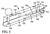
このような1つのシステム構成要素は、例えば、図1〜3に示されるような流動制御デバイス102である。流動制御デバイス102は、チャンバ108を画定する内部本体壁106を含む本体104を含む。本体壁106はまた、チャンバ108と流体連通する入口110、チャンバ108と流体連通する作業出口112、及びチャンバ108と流体連通する抽気出口114を含む。チャンバ108との流体連通を提供する作業出口112の開口部は、流動面積を有する。同様に、抽気出口114の開口部は、流動面積を有する。添付の図に示されるように、入口110、作業出口112、及び抽気出口114は各々、単一の開口部を備える。しかしながら、これらの特徴は各々、本開示の範囲内で、2つ以上の開口部及び/又は他の流体浸透性構造若しくは材料を備え得ることが理解されるべきである。
One such system component is, for example, a
流動制御デバイス102はまた、流動制御部材120を含む。流動制御部材120は、抽気出口114を流動する流体を選択的に調整又は制限するように適合された、任意の構造又は特徴の組み合わせを備えることができる。例えば、流動制御部材120は、抽気出口114を閉塞(部分的又は完全に)するように適合された単一又はマルチリーフのシャッタ機構(例えば、カメラのシャッタに類似する)を備えることができる。別の例では、流動制御部材は、抽気出口114の流路(複数可)の有効径(複数可)を縮小又は拡大するように抽気出口に作用する可変収縮を備えることができる。更に別の例では、流動制御部材120は、抽気出口114を閉塞(部分的又は完全に)するように適合されたゲート部材(例えば、ギロチンに類似する)を備えることができる。抽気出口を通る比例した流動制御を提供するように適合された任意の他のデバイスが、本開示の範囲内で流動制御部材120として使用されてもよい。
The
添付の図では、流動制御部材120は、チャンバ108内に少なくとも部分的に位置決めされた流動制御コアを備えるように示される。全体にわたって便宜上、流動制御コアは、流動制御部材120の例示的な実施形態として記載される。流動制御コアは、本明細書に記載されるように特定の利点を含み得るが、本開示によって企図される任意の流動制御部材120が全体にわたって流動制御コアに代用され得ることが理解されるべきである。
In the accompanying figures, the
流動制御コアは、流動制御コアがチャンバ108に対して再配置されると、流動制御コアの本体部分122が流動制御コアの本体部分122及び作動制御端部124を超えて、チャンバ108からの流体圧力の解放を制限する流体密封を維持するように、本体壁106の少なくとも一部分と摺動可能に密封係合にある本体部分を含む。
The flow control core is configured such that when the flow control core is repositioned relative to the
流動制御コアはまた、作動制御端部124及び先端部126を含む。先端部126は、内側部128及び遠位端部130を含む。遠位端部130は、流動制御コアがチャンバ108に対して前方に再配置されると、図2及び図3に示されるように、流動制御コアの遠位端部130の少なくとも一部分が抽気出口114の少なくとも一部分を閉塞するように、抽気出口114の流動面積未満の断面積を有する。
The flow control core also includes an
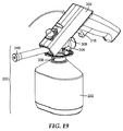
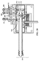
流動制御コアの作動制御端部124は、チャンバ108に対して流動制御コアを制御可能に再配置するための任意の好適な機構を含み得るアクチュエータを含むことができる。図1〜3は、アクチュエータが、例えば、流動制御コアに物理的に取り付けられたノブ132であり得る一実施形態を例示する。アクチュエータのノブ132をスロット134に沿って摺動させることが、チャンバ108に対して流動制御コアを再配置する。他の実施形態では、アクチュエータは、図11に例示されるように回転可能なハンドル138であってもよい。かかる実施形態では、ハンドル138の回転運動は、図12及び図13に示されるように、1つ以上の歯車機構136によってチャンバ108に対して流動制御コアの摺動する再配置に変換されてもよい。アクチュエータの特定の形態及び/又は設計は、アクチュエータがチャンバ108に対して流動制御コアを制御可能に再配置するように再配置されることが可能である限り重要ではない。
The flow control core
流動制御デバイス102を作動させることは、チャンバ108に対して流動制御部材120を再配置するいかなる様式も含むことができる。したがって、いくつかの実施形態(図示せず)では、チャンバ108に対して流動制御部材120を移動させることは、静止した流動制御部材120に対して本体104を再配置することを含むことができる。かかる実施形態では、アクチュエータは、本体104が流動制御部材120に対して再配置される間、流動制御部材120を静止して保持する構成要素に流動制御部材120を接続する取り付けであり得る。更に他の実施形態では、チャンバ108に対する流動制御部材120の移動は、流動制御部材120と本体104との両方の移動を含むことができる。かかる実施形態では、流動制御部材120及び本体104の移動は、反対方向であってもよく、又はチャンバ108、若しくはより具体的には、抽気出口114に対して流動制御部材120を再配置することをもたらす任意の同時移動を含むことができる。
Actuating the
図1は、第1の閉鎖位置におけるアクチュエータ132及び流動制御部材120(この場合、流動制御コア)を示す。図2及び図3は、流動制御部材120が中間位置(図2)を通って完全な前方位置(図3)にチャンバ108に対して再配置される流動制御デバイス102の進行性作動を例示する。図1は、流動制御コアの遠位端部130が抽気出口114を全く閉塞しないように流動制御デバイス102を例示するが、いくつかの実施形態では、流動制御コアの遠位端部130は、第1の位置において抽気出口114の一部分を閉塞することができる。同様に、図3は、流動制御コアの遠位端部130が抽気出口114を完全に閉塞することを例示するが、いくつかの実施形態では、流動制御コアの遠位端部130は、完全な前方位置において必ずしも抽気出口114を完全に閉塞しなくてもよい。
FIG. 1 shows the
図1〜3は、入口110が流動制御部材120の再配置全てにわたってチャンバ108と流体連通したままである一実施形態を例示するが、図4は、入口110とコア108との間の流体連通が第1の閉鎖位置において流動制御部材120の一部分によって遮断され得る一実施形態を例示する。
1-3 illustrate one embodiment in which the
いくつかの実施形態では、入口110は、入口110が流動制御部材によって遮断されていないと、圧力源からの圧力が入口110を通ってチャンバ108に伝達されるように、圧力源と流体連通し得る。入口110、流動制御部材120、抽気出口114、及び作業出口112の構成は、流動制御デバイス102を通って作業出口112から外へ伝達される微細レベルの圧力制御を可能にする。流動制御デバイス102は、急速な大量の分注に所望され得るなど、作業出口112を通って伝達される高い作業圧力、並びに作業出口112を通って低い作業圧力を伝達することによって可能になるなどの微細制御の両方を可能にすることができる。
In some embodiments, the
したがって、いくつかの実施形態では、流動制御デバイス102は、例えば、少なくとも0.010PSI(0.069kPa)、少なくとも0.020PSI(0.014kPa)、少なくとも0.030PSI(0.21kPa)、少なくとも0.033PSI(0.23kPa)、少なくとも0.036PSI(0.25kPa)、少なくとも0.040PSI(0.28kPa)、少なくとも0.043PSI(0.30kPa)、少なくとも0.046PSI(0.32kPa)、少なくとも0.050PSI(0.34kPa)、少なくとも.053PSI(0.37kPa)、少なくとも0.056PSI(0.39kPa)、少なくとも0.060PSI(0.41kPa)、少なくとも0.063PSI(0.43kPa)、少なくとも0.066PSI(0.46kPa)、少なくとも0.070PSI(0.48kPa)、少なくとも0.075PSI(0.52kPa)、少なくとも0.080PSI(0.55kPa)、少なくとも0.085PSI(0.59kPa)、少なくとも0.090PSI(0.62kPa)、少なくとも0.095PSI(0.66kPa)、又は少なくとも0.10PSI(0.69kPa)の最小値を有する作業圧力を送達することができる。流動制御デバイス102はまた、100PSI(689kPa)以下、90PSI(620kPa)以下、80PSI(552kPa)以下、70PSI(483kPa)以下、60PSI(414kPa)以下、50PSI(345kPa)以下、40PSI(256kPa)以下、30PSI(207kPa)以下、25PSI(172kPa)以下、20PSI(138kPa)以下、15PSI(103kPa)以下、10PSI(69kPa)以下、9PSI(62kPa)以下、8PSI(55kPa)以下、7PSI(48kPa)以下、6PSI(41kPa)以下、5PSI(34kPa)以下、4PSI(28kPa)以下、3PSI(21kPa)以下、2PSI(14kPa)以下、又は1PSI(7kPa)以下の最大作業圧力を送達することができる。流動制御デバイス102によって送達された作業圧力は、端点として、上記に列挙された任意の最小作業圧力及び最小作業圧力を超える上記に列挙された任意の最大作業圧力を有する範囲として表されてもよい。特定の一実施形態では、流動制御デバイス102は、0.036PSI(0.25kPa)の最小値を有し、かつ25PSI(172kPa)の最大値を有する一連の作業圧力を送達することができる。
Thus, in some embodiments, the
多くの従来の圧力調節デバイスは、「亀裂圧力」として知られているものを示す。この用語は、スパイクを有するゼロ圧力から上昇するデバイスの傾向に関する。このスパイクは、例えば、分注サイクルの急速な分注段階中に望まれ得る比較的高い圧力を更に加えることを可能にしながら、システムが制御された様式で非常に低い圧力を円滑かつ可変的に加え得る程度を制限することができる。急速な分注段階中に必要とされる圧力は、分注サイクルの低圧の精密な仕上げ段階中に必要とされる圧力を数百倍超える可能性がある。 Many conventional pressure regulating devices exhibit what is known as “crack pressure”. The term relates to the tendency of the device to rise from zero pressure with spikes. This spike, for example, allows the system to apply a very low pressure smoothly and variably in a controlled manner, while still allowing the relatively high pressure that may be desired during the rapid dispensing phase of the dispensing cycle to be applied. The degree of addition can be limited. The pressure required during the rapid dispensing phase can exceed the pressure required during the low-pressure precision finishing phase of the dispensing cycle by several hundred times.
流動制御デバイス102は、スパイク又は他の圧力の急上昇なしに、ゼロ圧力からユーザーによって制御される圧力に上昇するように設計される。これは、抽気出口114を含む「制御された抽気」戦略によって達成される。流動制御デバイス102がアイドル状態にあるとき、抽気出口114が最小限に閉塞される(又は閉塞されていない)ように流動制御部材が再配置される(例えば、流動制御コアの実施形態では、入口110がもはや遮断されないように図1に示される位置からわずか前方に)とき、入口110を通ってチャンバ108に伝達される圧力の大部分は、抽気出口114を通って解放される。
The
図21は、流動制御デバイス102の制御された抽気特徴が低圧で「亀裂圧力」の影響を受けやすい従来の流動制御設計と比較する様子を例示する。本明細書に記載されるように流動制御デバイス102から測定された作業圧力を表す曲線は、円滑な段階的な様式でゼロから上昇する。それに対して、従来のデバイスで代表的な「亀裂圧力」は、作業圧力がゼロから上昇するとき、圧力のスパイクを示す。「亀裂圧力」の存在は、スパイク内で消費される非常に低い圧力で作業圧力を正確かつ精密に制御するのを困難にする。
FIG. 21 illustrates the controlled bleed feature of the
一般的に、抽気出口114の流動面積と作業出口112の流動面積との比率は、抽気出口114を通って伝達される圧力に対して作業出口112を通って伝達される圧力の比率を決定する。本明細書で使用されるとき、「流動面積」は、流体出口を形成し、それを取り囲む表面の形状及び性質と共に、流体出口にわたって所定の圧力低下で所定の流体の流体出口を通る特定の流速をもたらすように共に作用する流体出口(例えば、抽気出口114又は作業出口112)の開放部分の断面積を意味する。例えば、第1及び第2の流体出口の共通の上流側の流体が特定の圧力である場合、流体は、どちらの流体出口がより大きい流動面積を構成するとしてもより高速で流動する。単純な円形オリフィス又は円環の場合、流動面積は、形状の開放断面積によって大部分は決定され得る。しかしながら、特定の表面特徴は、乱流又はより大きな流動抵抗を誘発し、それ故に流動面積の実質的な減少を引き起こし得る。更に、例として、流動制御コアの遠位端部130のプロファイル及び抽気出口114の内部プロファイルは、2つのプロファイルを所定の位置で入れ子にすると、多かれ少なかれ流動制限が実現され、それ故に多かれ少なかれそれぞれの流動面積をもたらすことができる。
In general, the ratio of the flow area of the
遠位端部130が抽気出口114の一部分を閉塞し始めるように流動制御コアが前方に再配置されるにつれて、抽気出口114の流動面積と作業出口112の流動面積との比率が変化し、その結果として、抽気出口114及び作業出口112を通って伝達される相対圧力が変化する。特定の実施形態では、流動制御デバイス102は、作業出口112を通って伝達された観測された圧力、即ち、「作業圧力」がほとんどゼロであり得るように、抽気出口114の流動面積と作業出口112の流動面積との比率で構成され得る。遠位端部130が抽気出口114を閉塞し始めるように、流動制御コアをゆっくりと前進させるにつれて、作業出口112を通って伝達される圧力は、円滑かつ制御可能な比率で増加する。これは、ユーザーが、例えば、正確かつ精密な分注が望ましくてもよい段階の仕上げ段階等の低圧分注段階中に分注される流体(例えば、塗料成分)の流速を容易に制御することを可能にする。
As the flow control core is repositioned forward so that the
流動制御コアを完全な前方位置に前進させると、抽気出口114の流動面積と作業出口112の流動面積との比率は最小限にされ、作業出口112を通って伝達される圧力は最大限にされ、流体の急速な分注を可能にする。流動制御コアが完全な前方位置(例えば、図3に示されるような)にあるとき、抽気出口114が完全に閉塞される実施形態では、作業出口112を通って伝達される圧力は、入口110を通って流動制御デバイス102に供給される圧力にほぼ等しい。高圧及び低圧の両方でのこれらの流動制御特性の組み合わせは、流体(例えば、高圧)、並びに「亀裂圧力」現象を経験することなく分注する容易な、正確な、及び/又は精密な低圧を急速に分注することを可能にする。
When the flow control core is advanced to a fully forward position, the ratio of the flow area of the
流動制御コアの先端部126は、流動制御コアが抽気出口114の少なくとも一部分を閉塞するように前方に再配置されるにつれて、任意の所望の圧力転移パターンを提供するように構成され得る。図1〜3に示される流動制御コアは、直径の段階的増大を有する相対的に長い先端部126を有する。このような設計は、流動制御コアが前方に再配置されるにつれて、作業出口112に伝達される、なだらかで段階的かつ均一な圧力の増加をもたらすことができる。しかしながら、流動制御コアの先端部126の他の構成が設計されてもよい。例えば、より短い遠位端部130及びより少ない段階的な先細りを保有する先端部126は、先端部126が抽気出口114を少なくとも部分的に閉塞するように前方に再配置されるにつれて、作業出口112を通って伝達される圧力をより急速に増加させることができる。(例えば、図4及び図5参照)。このような設計は、例えば、微細な低圧分注を必要としない流体を分注するのに望ましい場合がある。別の例として、より長い先端部126は、先端部126が抽気出口114を少なくとも部分的に閉塞するように前方に再配置されるにつれて、更により段階的な直径の増大及び作業出口112を通って伝達される圧力の対応する、より段階的な増加を可能にし得る。これは、例えば、微細な、精密な、正確な測定値が最重要である流体を分注するのに望ましくてもよい。このような設計は、アイドル位置では、遠位端部130が抽気出口114の部分を閉塞しない図1に示されるなどの構成によって補完されてもよい。最終的な一例として、先端部126は、先端部126の直径が変化する速度のように設計されてもよい。例えば、遠位端部130は、なだらかな段階的な直径の増大で長く、狭くてもよいが、内側部128は、遠位端部130の直径の増大より急速に直径を増大し得る。このような構成は、遠位端部130のなだらかな段階的に増大する直径により、低圧で精密に分注する能力を組み合わせ、次いで、流動制御コアが前方に再配置されるにつれて、内側部128のより急速な直径の増大及び抽気出口114の対応する、より急速な閉塞により、急速な高圧分注に急速に遷移することができる。
The flow
先端部126が任意の所望の圧力転移パターンを提供するように構成され得ることにより、流動制御コアは、遠位端部130が取り替え可能部品であり得るように構成され、所定の用途に適切である圧力転移パターンを送達する流動制御コアの取り替え可能な遠位端部130を選択することを可能にし得る。したがって、いくつかの実施形態では、流動制御コアは、交換可能な遠位端部130と連結するための任意の適切な機構を含むように構成されてもよい。例示的な連結機構としては、ねじ切り、コレット、スナップ嵌め、又はプレス嵌めが挙げられ得る。いくつかの実施形態では、これは、遠位端部130が部品を取り替えるのに利用しやすいように、図3に示されるような位置に流動制御コアを前進させるために使用する前に可能であり得る。
The
いくつかの実施形態では、抽気出口114は、抽気出口封止部116を含むことができる。抽気出口封止部116は、流動制御部材120で流体密封(例えば、図示される実施形態では、流動制御コアの先端部による摺動する流体密封)を提供し得る任意の材料で構成されてもよい。したがって、抽気出口封止部116は、例えば、天然又は合成ゴム等のエラストマー材料を含むことができる。
In some embodiments, the
いくつかの実施形態では、抽気出口114は、流体リザーバと流体連通し得る。これらの実施形態のうちのいくつかでは、流体リザーバはまた、入口110と流体連通し得る。かかる実施形態では、流動制御デバイス102への圧力源から流体圧力を伝達するために使用される流体は(液体であろうと気体であろうと)再利用され得る。
In some embodiments, the
いくつかの実施形態では、作業出口112は、作業装置と流体連通し得る。一般的に、作業装置は、機械的機能を達成するために作業出口112からそれに伝達される圧力を利用し得る任意の装置であってもよい。図11に例示されるシステムでは、作業装置としては、例えば、液体の分注器が挙げられ得る。より具体的には、作業出口112は、特定の圧力調節された機能を果たすように構成された作業装置の構成要素と流体連通し得る。図14に例示され、図6〜9に概略的に表されるシステムでは、作業出口112は、流体連通し、それ故に、例えば、バルブ本体のアクチュエータ及び/又はバルブ本体のクランプの機能を調節することができる。
In some embodiments, the
前述のように、抽気出口114の流動面積が作業出口112の流動面積より大きいと、流動制御デバイス102は、ほとんどゼロの作業圧力を発生することができる。したがって、いくつかの実施形態では、抽気出口114の流動面積は、所定の比率で作業出口112の流動面積より大きくてもよい。所定の比率は、例えば、少なくとも10:1、少なくとも15:1、少なくとも20:1、少なくとも25:1、少なくとも30:1、少なくとも35:1、少なくとも40:1、少なくとも45:1、少なくとも50:1、少なくとも55:1、少なくとも60:1、少なくとも65:1、少なくとも70:1、少なくとも75:1、少なくとも80:1、少なくとも85:1、少なくとも90:1、少なくとも95:1、少なくとも100:1、又は少なくとも105:1など、少なくとも5:1の最小値を有する比率であってもよい。所定の比率は、120:1以下、110:1以下、100:1以下、95:1以下、90:1以下、85:1以下、80:1以下、75:1以下、70:1以下、65:1以下、60:1以下、55:1以下、50:1以下、45:1以下、40:1以下、35:1以下、30:1以下、25:1以下、又は20:1以下の最大値を有する比率であってもよい。所定の比率はまた、端点として、上記に列挙された任意の最小比率及び最小比率を超える上記に列挙された任意の最大比率を有する範囲として表されてもよい。様々な特定の実施形態では、抽気流動面積と作業流動面積との比率は、例えば、10:1、25:1、50:1、又は64:1であり得る。
As described above, if the flow area of the
上述される流動制御デバイス102の様々な実施形態は、流体分注システムの構成要素であってもよい。いくつかの場合では、流体分注システムは、図11に例示されるシステム等の卓上流体分注システム200であってもよい。いくつかの場合では、流体分注システムは、図19に例示されるシステム等のハンドヘルド流体分注システム300であってもよい。卓上システムであろうとハンドヘルドシステムであろうと、流体分注システムは、概して、カプラ、圧力出口、及びアクチュエータを含む筐体と、上述されるように、アクチュエータと機械的連通し、及び/又はそれと流体連通し、かつ圧力出口と流体連通する流動制御デバイス102とを含む。システムはまた、流体リザーバと、筐体カプラを介して流体リザーバを筐体に連結する、より詳細に後述されるキャップ及びバルブのアセンブリと、を含む分注器アセンブリを含む。
Various embodiments of the
例示的なハンドヘルド分注システム300が、図19に例示される。ハンドヘルドシステムは、圧力源と流体連通し、かつ圧力出口304と流体連通する流動制御デバイス102(図示せず)を含む筐体302を含む。圧力出口304は、より詳細に後述される分注アセンブリ200の圧力入口の構成要素と整列し、及び/又は別の方法でそれとの流体連通を提供するように構成されてもよい。流動制御デバイスはまた、アクチュエータ318と係合される。筐体302はまた、カプラ306を含む。図19に示される実施形態では、カプラ306は、分注器アセンブリ220上の受容スロットに係合するように構成される一連の留め金308を含む。図19は、分注アセンブリに係合する留め金308の1つの例示的な構成を例示する。
An exemplary handheld dispensing system 300 is illustrated in FIG. The handheld system includes a
いくつかの実施形態では、ハンドヘルドシステム300は、空間制限により、流動制御デバイス102のいくらかより単純な設計を利用することができる。ハンドヘルドデバイス300での使用に好適な1つの例示的な流動制御デバイス102の設計は、図4及び図5に例示される。使用時に、アクチュエータ318(図19)を押し下げることは、流動制御コアを図4に示されるなどの元の位置から図5に示されるなどの作動位置に再配置することができる。図5に示される作動位置では、圧力が入口110を通って流動制御デバイス102に入り、チャンバ108を横断し、作動の程度に応じて、抽気出口114及び/又は作業出口112を通ってチャンバを出る。作業出口112(図5に示される)は、ハンドヘルドシステム300の筐体302内の圧力出口304(図19に示される)と流体連通している。作業出口112から伝達された圧力は、その後、圧力出口308を通って分注アセンブリ220に伝達される。
In some embodiments, the handheld system 300 can utilize a somewhat simpler design of the
例示的な卓上流体分注システム200が、図11に例示される。卓上システム200は、分注アセンブリ220を密封受容し、及び/又はそれに係合するように構成されたカプラ206(図14及び図17により詳細に示される様々な構成要素)を含む筐体202を含む。筐体はまた、圧力出口204及びアクチュエータ218を含む。卓上システム200は、圧力源(例えば、流動制御デバイス102を通る)と圧力出口204との間に流体連通を提供する。圧力出口204は、より詳細に後述される分注アセンブリ200の圧力入口の構成要素と整列し、及び/又は別の方法でそれとの流体連通を提供するように構成されてもよい。
An exemplary tabletop
カプラ206は、分注アセンブリ220の少なくとも一部分を受容し、及び/又はそれに密封係合するように構成された連結機構208を含む。図14及び図17に示される実施形態では、連結機構は、分注アセンブリ220の少なくとも一部分に補完的であるように構成されたスロット型取り付け210を含むことができる。いくつかの実施形態では、連結機構208は、分注アセンブリ220の一部分に係合し、かつ卓上システム200との使用中に分注アセンブリ220を適所に保持するように構成されたクランプを含むことができる。連結機構208としてクランプを含む実施形態では、クランプは、手動で操作され、又はいくつかの実施形態では、卓上システム200からの流体圧力によって作動され得る。クランプが卓上システム200からの圧力を用いて操作される実施形態では、クランプは、掴持されるとき、圧力信号を分注アセンブリ220に伝達するクランプ/マニホールドアセンブリ212を含むことができる。クランプはまた、掴持力をクランプ/マニホールドアセンブリ212に供給し得るクランプアクチュエータ214を含むことができる。カプラ206及び分注アセンブリ220の補完的構成は、図22により詳細に示される。
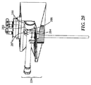
図25〜29に示されるいくつかの実施形態では、カプラは、分注アセンブリ220が卓上デバイス200内に位置決めされるとき、キャップ及びバルブのアセンブリ224と別々に係合し得る別個のアクチュエータ287、288、及び289を含むことができる。マニホールドアセンブリ(図25の291、図26の292)から送達される圧力は、アクチュエータ287、288、及び289の運動を制御することができる。圧力は、図29に示される1つ以上のマニホールド入口290を介してマニホールドアセンブリに送達されてもよい。図25及び図27は、キャップ及びバルブのアセンブリ224の対応構造(それぞれ234、280、及び282)と係合されないアクチュエータ287、288、及び289を示す。第1のマニホールド部分291に送達される圧力信号(即ち、「上方」信号)(図25の断面に示される)は、アクチュエータを図25、27、及び29に示される位置に位置決めすることができる。第2のマニホールド部分292に送達される圧力信号(即ち、「下方」信号)(図26の断面に示される)は、アクチュエータを図25、27、及び29に示される位置から図26及び図28に示される位置に再配置することができる。
In some embodiments shown in FIGS. 25-29, the coupler may include a
いくつかの実施形態では、第1のマニホールド部分291及び第2のマニホールド部分292から送達される単一圧力信号はそれぞれ、アクチュエータの全てを制御することができ、これは各々が、他のアクチュエータとは独立して移動可能であり得る。即ち、アクチュエータ287、288、及び289は、第1のマニホールド部分291内の単一圧力信号によって制御されるが、各アクチュエータは、図26及び図28に示されるように、キャップ及びバルブのアセンブリ244の対応構造(それぞれ234、280、及び282)に係合するのに必要な程度に他のアクチュエータとは独立して移動することができる。同様に、第2のマニホールド292内の単一信号は、アクチュエータ287、288、及び289の運動を反転することができる。
In some embodiments, each single pressure signal delivered from the
いくつかの実施形態では、アクチュエータ287、288、及び289とそれらのそれぞれの対応構造234、280、及び282との間の封止部は、各アクチュエータの係合端部上に配設された封止部材によって提供される。一実施形態では、封止部材は、取り外し可能かつ交換可能である。一実施形態では、封止部材は、手で(即ち、工具を使用せずに)取り外し可能かつ交換可能である。いくつかの実施形態では、封止部材は、オーバーモールドによって形成されるなど、一体である。
In some embodiments, the seals between the
アクチュエータ218は、分注器アセンブリ220を作動させるように構成され、それにより圧力出口204から分注器アセンブリへの流体圧力の送達を可能にする。
図14は、従来の加圧システムの一部であり得る追加の任意の構成要素を示す。これらの従来の構成要素は、例えば、圧力源215A及び215B並びに安全バルブ217A及び217Bを含む。
FIG. 14 illustrates additional optional components that may be part of a conventional pressurization system. These conventional components include, for example,
使用時に、ユーザーは、システムへの圧力の流動を作動させるハンドル138を操作する。いくつかの場合では、ハンドルは、後述されるように、流動制御デバイス102のノブ132(図1〜3)又は回転ハンドル138(例えば、図11)に相当し得る。流動制御デバイス102が関わるかどうかにかかわらず、ハンドルを操作することより、卓上システム200に圧力を導入する。圧力は、筐体202内の圧力出口204に伝達され、そこでそれは、カプラ206の中に固定された分注アセンブリ220の対応する圧力入口に更に伝達され得る。このように、卓上システム200から分注アセンブリ220に伝達される圧力は、ユーザーが分注アセンブリ220から流体を制御可能に分注することを可能にする。
In use, the user operates a
いくつかの実施形態では、カプラ206及びアクチュエータ218のうちの1つ又はその両方は、ユーザーがカプラ206及び/又はアクチュエータ218の機能を制御することができるコントローラと流体連通し得る。これらの実施形態のうちのいくつかでは、カプラは、第1のコントローラと流体連通することができ、アクチュエータは、第2のコントローラと流体連通することができる。これらの実施形態のうちのいくつかでは、第1及び第2のコントローラは、シーケンサアセンブリ400(図14、図20に詳細に示される)の構成要素であり得る。
In some embodiments, one or both of
シーケンサアセンブリ400は、ユーザーが通常の分注サイクル中に生じる事象のタイミング及び順序を制御することを可能にし得る。シーケンサアセンブリがないと、ユーザーが急速な充填(即ち、高圧)状態から停止/バルブ閉鎖状態に突然遷移する場合、分注アセンブリの流体リザーバ部分内に残留圧力が蓄積され得る。次に、この残留圧力は、リザーバの分注アセンブリが使用される次回解放されてもよい。次のユーザーは、残留圧力が流体リザーバ内に蓄積されることに気付かない場合があり、蓄積された圧力の予期せぬ解放は、流体溢出又は他の偶発性事故をもたらし得る。残留圧力を避けるために、卓上システム200のカプラ206から分注デバイス220を解放する前に、分注デバイス220への圧力を遮断することができる。これらの工程の適切な順序を達成する1つの方法は、市販の空気論理ブロックを利用することである。しかしながら、これらのデバイスは費用がかかり得る。したがって、我々は、代替的シーケンスアセンブリ400を考案した。
The
例示的なシーケンサアセンブリ400が、図20に例示される。シーケンサアセンブリ400は、ルーメン404を画定する本体壁402を含む。第1の圧力入口406は、例えば、上述される流動制御デバイス102の作業出口112等、ルーメン404と圧力源との間に流体連通を提供する。第2の圧力入口407は、例えば、流動制御デバイス102のシーケンサアセンブリの制御バルブ140等、ルーメン404と圧力源との間に流体連通を提供する。シーケンサアセンブリ400は、第1のシーケンサバルブ410と、第1のシーケンサ制御部408と第1の出力デバイスとの間に流体連通を提供する第1の圧力出口412と、を含む、第1のシーケンサ制御部408、並びに第2のシーケンサバルブ416と、第2のシーケンサ制御部414と第2の出力デバイスとの間に流体連通を提供する第2の圧力出口418と、を含む、第2のシーケンサ制御部414を更に含む。シーケンサアセンブリ400はまた、ルーメン404内に摺動可能に位置決めされ、かつルーメン内の位置が圧力入口406を通ってルーメン404への圧力の伝達によって制御されるシーケンサコア424を含む。
An
シーケンスアセンブリ400は、図14に示されるように流動制御デバイス102と流体連通し得る。流動制御デバイス102は、上述されるように卓上システムのカプラ206及び分注アセンブリ220と流体連通している。流動制御デバイス102はまた、シーケンサアセンブリと流体連通している。図1〜3は、複数の作業出口112を介して2つ以上のシステム構成要素に流体連通を提供するように構成された流動制御デバイス102の一実施形態を例示する。図12及び図13は、シーケンサアセンブリの制御バルブ140を通ってシーケンシングアセンブリ400に流体連通を提供するように構成された実施形態を示す。流動制御デバイス102の作動は、分注アセンブリ220に圧力を伝達するだけでなく、第1の圧力入口406を通ってシーケンサアセンブリ400に圧力も伝達し、シーケンサコア424(図20に示される)を作動させる。
The
図20に示される実施形態では、シーケンサコア424が第1の圧力入口406を通って伝達される圧力の結果としてルーメン404内に前進されると、それは最初に、第1のシーケンサバルブ410を作動させる。シーケンサコア424が更に前進されると、それは最終的に、第2のシーケンサバルブ416を作動させる。シーケンサコア424が行過ぎ距離420に沿って更に前進されると、更なる作動は生じない。行過ぎ距離420は、流体の分注が完了すると、「遮断」順序の段階の時間を計るために使用される。
In the embodiment shown in FIG. 20, when the sequencer core 424 is advanced into the
流体を分注することが終了し、ユーザーが流動制御デバイス102のアクチュエータを閉鎖又は「オフ」位置に戻すと、流動制御部材120(例えば、図示される実施形態における流動制御コア)は、シーケンサアセンブリの制御バルブ140を作動させ、流動制御デバイス102からの圧力を、シーケンサアセンブリの制御バルブ140を通って、第2の圧力入口407を通ってシーケンサアセンブリのルーメン404に伝達する。(図13及び図14)。この圧力は、シーケンサコア424を格納し、最初に第2のシーケンサバルブ416から係合解除し、次いで第1のシーケンサバルブ410から係合解除し、それにより最初に第2のシーケンサ制御部414への圧力を遮断し、次いで第1のシーケンサ制御部408への圧力を遮断する。圧力が各シーケンサ制御部から遮断されると、第1の出力デバイス及び第2の出力デバイスへの圧力の供給は分断され、それらの出力デバイスは、順に機能するのを停止する。
When the dispensing of fluid is complete and the user returns the actuator of the
一実施形態では、第1の出力デバイスは、図11に示されるように、卓上流体分注システム200内のカプラ206として機能する流体圧力駆動クランプであってもよい。このような一実施形態における第2の出力デバイスは、図11に示されるようなアクチュエータ218であってもよい。このような一実施形態では、第1のシーケンサバルブ410を超えるシーケンサコア424の運動は、圧力が第1のシーケンサ制御部408から第1の圧力出口412を通って第1の出力デバイス、例えば、分注アセンブリを卓上システムの筐体202のカプラ206内の適所に掴持する、流体圧力駆動クランプに伝達されることをもたらす。シーケンサコア424が前進し続けると、それは、第2のシーケンサバルブ416を作動させ、圧力が第2のシーケンサ制御部414から第2のシーケンサ出口418を通って第2の出力デバイス、例えば、アクチュエータ218に伝達されることをもたらす。
In one embodiment, the first output device may be a fluid pressure driven clamp that functions as a
分注が完了し、シーケンサコア424がその格納を始めると、それは最初に、行過ぎ距離420に沿って格納する。行過ぎ距離420を横断するためにシーケンサコア424に必要とされる移動時間は、シーケンサコア424が第2のシーケンサバルブから係合解除する前に、分注アセンブリの中に導入される残留圧力が解放され得るアイドル時間を提供し、それによりアクチュエータ218への圧力の供給を分断し、そのアクチュエータを遮断する。シーケンサコア424が格納し続けるにつれて、それは、第1のシーケンサバルブ410から係合解除し、カプラ206の流体圧力駆動クランプへの圧力の供給を分断し、そのクランプを遮断し、ユーザーが卓上システム200から分注デバイス220を取り外すことを可能にする。この様式で提供される移動時間量は、シーケンサのアクチュエータに取り付けられた可変流動制御によって少なくとも一部制御される。
When dispensing is complete and the sequencer core 424 begins to store it, it first stores along the
いくつかの実施形態では、シーケンサアセンブリは、第3のシーケンサ制御部であって、第3のシーケンサバルブ、及び第3のシーケンサ制御部と第3の出力デバイスとの間に流体連通を提供する第3の圧力出口を含む、第3のシーケンサ制御部を含むことができる。システムの電源を切るシーケンシングは、2つのシーケンシング制御設計のために詳細に記載されるものと同じ様式で、3つの出力デバイスを制御する3つのシーケンサ制御部と連動することができる。行過ぎ距離420及びシーケンサ制御部間の空間を設計して、出力デバイスの電源を切る適切なタイミング遅延を提供することができる。
In some embodiments, the sequencer assembly is a third sequencer controller that provides fluid communication between the third sequencer valve and the third sequencer controller and the third output device. A third sequencer controller may be included, including three pressure outlets. Sequencing to power off the system can work with three sequencer controls that control the three output devices in the same manner as described in detail for the two sequencing control designs. The space between the
流体分注システムが卓上システムであろうとハンドヘルドシステムであろうと、システムは、流体リザーバ222、並びにキャップ及びバルブのアセンブリ224を概して含む分注アセンブリ220を含む。様々な図に例示される実施形態では、流体リザーバ222は、瓶として例示される。しかしながら、流体リザーバ222は、例えば、パウチ、袋、箱、缶、キャニスタ等の流体を収容するのに好適な任意の形態であり得る。例えば、上述される卓上システム200の1つの特徴は、それが画定された形状、例として少なくとも半剛壁を有する瓶又はキャニスタを有する必要がない流体リザーバ222と組み合わせて使用され得ることである。流体リザーバ222がカプラ206を介して卓上システム222の中に固定されることにより、流体は、流体リザーバ222から分注され得るが、流体リザーバ222は、図11に示されるように、卓上システムの筐体202のカプラ206からキャップ及びバルブのアセンブリ224によって一時停止される。したがって、流体リザーバ222は、流体の効率的な正確な分注を可能にするために剛性又は半剛性構造を保有する必要がない。
Whether the fluid dispensing system is a tabletop system or a handheld system, the system includes a
キャップ及びバルブのアセンブリ224は、概して、流体リザーバ222上の開口部と密封係合するように構成されたキャップ226を含む。多くの場合、流体リザーバ222とキャップ226との間の密封係合は、「ねじキャップ」タイプ適合を可能にする補完的なねじ切りを含む。しかしながら、例えば、クランプ又はスナップ嵌めを含む他の連結戦略も可能である。より詳細に後述されるモジュール部品を有するキャップ及びバルブのアセンブリを含むもの等のいくつかの実施形態では、キャップ226は、流体リザーバ222の開口部との密封係合が不可逆であるように構成されてもよい。キャップ226はまた、キャップ226を通って流体リザーバ222の内部に流体連通を提供する圧力入口228、及び流体リザーバ222内に収容される流体と流体連通する流動入口230を含む。
The cap and
キャップ及びバルブのアセンブリ224は、圧力カプラ234、出口開孔238、流動入口230と出口開孔238との間に流体連通を提供するルーメン236、ルーメン236内に配設された再配置可能なバルブコア240、並びにコア制御開孔280及び282を含む細長い部材232を更に含む。圧力カプラ234は、流体分注システム(200又は300それぞれ)の圧力出口(204又は304)と整列又は別の方法で流体連通を提供するように構成されてもよい。この整列又は他の流体連通は、システムによって流体を分注するための流体リザーバ222に提供された圧力の送達を可能にする。圧力出口(204又は304)を通ってシステムによって提供された圧力は、流動制御デバイス102を通ってユーザーによって制御されてもよい。
The cap and
再配置可能なバルブコアは、少なくとも2つの位置に配設されてもよい。図15に例示される第1の位置では、バルブコア240は、圧力カプラ234と圧力入口228との間の流体連通を遮断する。この位置では、バルブコア240は、システムから流体リザーバ222への加圧を遮断し、したがって、流体リザーバ222から、流動入口230、細長い部材232のルーメン236を通って、出口開孔238から出る流体の流動を遮断する。
The repositionable valve core may be disposed in at least two positions. In the first position illustrated in FIG. 15, the
しかしながら、図16に例示される第2の位置では、バルブコア240は、圧力カプラ234から圧力入口228に流体連通を提供するように作動され、それにより流体リザーバ222への圧力を提供する。この位置では、流体リザーバ222に伝達された圧力は、リザーバ222から流動入口230を通って出て、細長い部材232のルーメン236を通って、出口開孔238から出る。
However, in the second position illustrated in FIG. 16, the
再配置可能なバルブコア240は、コア制御開孔280及び282を通って圧力を加えることによって再配置されてもよい。コア制御開孔280を通って加えられる圧力は、再配置可能なバルブコア240を前方に、即ち、第1の位置から直前に記載される第2の位置に向かう方向に再配置する。制御開孔282を通って加えられる圧力は、再配置可能なバルブコア240を後方に、即ち、第2の位置から直前に記載される第1の位置に向かう方向に再配置する。これに関連して、図15及び図16に例示される第1の位置及び第2の位置への言及は、再配置可能なバルブコア240の移動の一般的な方向を例示するように提供される。使用時に、圧力は、第1の位置及び第2の位置に完全に到達することなく、コア制御開孔280及び282を通って加えられてもよい。図16に示される第2の位置では、圧力カプラ234と圧力入口228との間の流体連通は、分注圧力がリザーバ222上の流体に加えられ得るように確立される。
The
アクチュエータ287、288、及び289がキャップ及びバルブのアセンブリ224に別々に係合する図26及び図28に例示される実施形態では、アクチュエータ287、288、及び289は、圧力がリザーバ222からの流体の分注を制御するためにアクチュエータを通って送達され得るように、圧力カプラ234、コア制御開孔280、及びコア制御開孔282と整列するように構成されてもよい。
In the embodiment illustrated in FIGS. 26 and 28 where the
いくつかの実施形態では、細長い部材232は、例えば、ルーメン236の内容物を見ることを可能にするように十分に透明な材料で構築されてもよい。
In some embodiments, the
上述され、かつ図19に例示されるハンドヘルドシステム300では、バルブコア240は、アクチュエータ318の機械的作用によって第2の位置に作動されてもよい。上述され、図10に例示される卓上システム200では、バルブコア240は、上述され、図14及び図20に例示されるシーケンサアセンブリ400によって制御される流体圧力駆動アクチュエータ218(図11及び図14)によって作動されてもよい。
In the handheld system 300 described above and illustrated in FIG. 19, the
キャップ及びバルブのアセンブリ224は、流体分注システム(200又は300それぞれ)の筐体(202又は302)上のカプラ(206又は306)によって受容され、及び/又は別の方法で係合されるように構成された筐体カプラ242を更に含むことができる。図19に例示されるハンドヘルドシステム300に関連して、筐体カプラ242は、留め金308(図18)によって係合されるように構成されたスロットのように単純であってもよい。卓上システム200に関連して、筐体カプラ242は、スロット型取り付け210(図17)によって受容されるように構成された1つ以上の肩部244を含むことができる。いくつかの実施形態では、筐体カプラ242は、筐体202上のカプラ206上の位置決め小節に係合するように構成された位置決め溝を更に含むことができる。
The cap and
いくつかの実施形態では、キャップ及びバルブのアセンブリ224は、図25〜29に示されるようにロックピン286と係合するように構成されたフランジ284を更に含むことができる。図25〜29に示される実施形態では、ロックピン286は、アクチュエータ287、288、及び289の制御と同様にマニホールドアセンブリ212によって制御されてもよい。図25、図27、及び図29は、ロックピン286がキャップ及びバルブのアセンブリ224の任意の部分と係合されない、第1の位置におけるロックピン286を示す。圧力信号を印加すると、ロックピン286は、ロックピン286がキャップ及びバルブのアセンブリ224のフランジ284と係合し、分注アセンブリ220を適所にロックする、図26及び図28に示される第2の位置に移動する。
In some embodiments, the cap and
いくつかの実施形態では、キャップ及びバルブのアセンブリ224は、細長い部材232の端部を覆う、再配置可能な先端カバー248を更に含むことができる。一方の位置では、先端カバー248は、出口開孔238を覆い得るが、第2の位置では、先端カバーは、出口開孔238を暴露し得る。他のデバイスとは対照的に、先端カバー248の再配置は、バルブコア240の再配置及び流体リザーバ222への圧力の対応する伝達から独立し得る。その結果として、先端カバー248を再配置して、出口開孔を暴露することは、出口開孔238を通って流体を分注することを必ずしももたらさない。先端カバー248を位置決めして、出口開孔238を覆うことは、流体の分注が完了した後に出口開孔238でとどまる残留流体の出口開孔238を洗浄することができる。いくつかの実施形態では、先端カバー248は、細長い部材232の長軸の周囲に回転可能であってもよい。そうすると、出口開孔238を覆う先端カバー248の部分上の乾燥した流体の蓄積を制限することに役立つことができる。
In some embodiments, the cap and
先端カバー248は、交換可能な構成要素であるように構成され得る。いくつかの実施形態では、それは、細長い部材232の端部上を摺動するように構成される単一部品であってもよい。他の場合では、それは、例えば、細長い部材232の端部上に共にスナップ嵌めされ得る2つの部分の部品として製造されてもよい。
The
いくつかの実施形態では、バルブコア240は、封止部250を更に含むことができる。封止部は、図16に示されるようにバルブコア240が流体の分注を提供するように位置決めされると、封止部250が出口開孔238の遠位にあり、バルブコア240が図15に示される位置にあると、封止部250が出口開孔238の近位にあるように構成されてもよい。したがって、封止部250は、先端カバー248が出口開孔238を覆うように位置決めされない場合に、出口開孔238と、ルーメン236、流動入口230、及び/又は流体リザーバ222との間の流体連通を妨げることができる。したがって、封止部250は、例えば、分注アセンブリ220の保管中など、分注事象中にルーメン236又は流動入口230内の流体の不用意な乾燥を抑止することができる。
In some embodiments, the
いくつかの実施形態では、キャップ及びバルブのアセンブリ224は、第2の流体リザーバと係合するように構成されたキャップインサート252を更に含むことができる。したがって、キャップインサート252は、一連の異なる流体リザーバと共に単一のキャップ及びバルブのアセンブリ224を使用することを可能にし得る。あるいは、様々な製造者(例えば、塗料製造者)が様々なキャップサイズ及び/又は例えば、ねじのピッチを有する容器を使用することにより、キャップインサート252は、自動車整備工場が、任意の特定の製造者によって提供された容器に適合するために、例えば、単一キャップを有するキャップ及びバルブのアセンブリを注文し、かつキャップインサート252を使用して、キャップ及びバルブのアセンブリ224を適合させることを可能にする。
In some embodiments, the cap and
いくつかの実施形態では、キャップ及びバルブのアセンブリは、モジュールのキャップ構成要素526、及び細長い部材の構成要素532を含むことができる。即ち、キャップ及び細長い部材は、単一のキャップ構成要素526が様々な細長い部材設計と取り替え可能に使用され得るように、互いに取り外し可能であるように構成されてもよい。同様に、単一の細長い部材の構成要素532は、図24に例示されるように、様々なキャップ設計と取り替え可能に使用されてもよい。このようなキャップ及びバルブのアセンブリのモジュール特質は、ユーザーが、例えば、キャップ及びバルブのアセンブリの一部分のみを交換し、かつ将来の使用のために更に適合される一部分を保持することを可能にし得る。例えば、細長い部材は、例えば、流体(例として、塗料成分)がルーメン又は出口開孔内を乾燥及び/又は硬化し得ることにより使用不可になり得る。このような場合では、キャップは、完全に機能的なままであり得る。キャップ及びバルブのアセンブリのモジュール特質は、更に機能的なキャップ構成要素の使用を保持しながら、ユーザーが細長い部材を交換することを可能にする。同様に、ユーザーは、更に機能的な細長い部材の構成要素の使用を保持しながら、機能しないキャップ構成要素を交換することができる。
In some embodiments, the cap and valve assembly may include a module cap component 526 and an
したがって、図23及び図24に例示されるもの等の構成要素を概して含むキットを提供することができる。図24に示されるように、キャップ構成要素526は、流体リザーバ(222A及び222B)並びに細長い部材の構成要素532と密封係合するように構成されてもよく、これらの各々が、他と連結するように構成される。図24に示されるように、キャップ構成要素526は、細長い部材の構成要素532からキャップ構成要素526への圧力の伝達を容易にするために、細長い部材の構成要素532上の圧力オリフィス564と整列するように構成された圧力入口528を含むことができる。同様に、細長い部材の構成要素532は、キャップ構成要素526上の流動オリフィス568と整列するように構成された流動開孔566を含み、流動オリフィス568と細長い部材の構成要素532のルーメンとの間に流体連通を提供することができる。
Thus, kits can be provided that generally include components such as those illustrated in FIGS. As shown in FIG. 24, the cap component 526 may be configured to sealingly engage the fluid reservoirs (222A and 222B) and the
キャップ構成要素526と細長い部材の構成要素532との間の連結は、構成要素の互換性を提供しながら、流体を機能的に分注するために組み立てられたキャップ及びバルブのアセンブリに十分な構造的一体性を提供する任意の好適な連結であってもよい。好適な連結としては、例えば、スナップ嵌め又はプレス嵌めが挙げられ得る。したがって、細長い部材の構成要素は、キャップ構成要素526上の補完的な連結機構562と連結するように構成された連結機構560を含む。図24に示される実施形態では、細長い部材の構成要素532は、キャップ構成要素526上の連結機構562としてスロットと連結するように構成された連結機構560としてロックタブを含む。
The connection between the cap component 526 and the
モジュールの細長い部材の構成要素と連結するように構成されたカプラに加えて、モジュールのキャップ構成要素526は、例えば、筐体カプラ又はキャップインサートを含む上述されるキャップ及びバルブのアセンブリ224のキャップ部分の様々な実施形態の任意の1つ以上の特徴を含むことができる。同様に、モジュールのキャップ構成要素と連結するように構成されたカプラに加えて、モジュールの細長い部材の構成要素532は、例えば、図23に示されるように先端カバー548若しくは封止部550、又は透明な材料からの構築物を含む上述されるキャップ及びバルブのアセンブリ224の細長い部材部分の様々な実施形態の特徴のうちの任意の1つ以上を含むことができる。
In addition to the coupler configured to couple with the module elongated member component, the module cap component 526 includes a cap portion of the cap and
図24はまた、モジュールの構成要素の互換性を例示する。図示される例では、単一の細長い部材の構成要素532は、2つの異なる流体リザーバ222A及び222Bそれぞれとの使用に適合されるキャップ構成要素526A及び526Bと使用されるように構成される。各キャップ構成要素526A及び526Bは、細長い部材の構成要素532の単一設計と連結するように同様に構成される。各キャップ構成要素526A及び526Bは、同様に構成された圧力入口528、並びに細長い部材の構成要素532の圧力オリフィス564及び流動開孔566と整列するように構成された流動オリフィス568を有する。各キャップ構成要素はまた、細長い部材の構成要素532のロックタブ560に係合するための同様に構成されたスロット562を有する。
FIG. 24 also illustrates module component compatibility. In the illustrated example, a single
各キャップ構成要素526A及び526Bはまた、本明細書に記載されるような卓上システムと係合するために同様に構成された肩部544を含む、同様に構成された筐体カプラ542を有する。
Each
各流体リザーバ222A及び222Bは、異なるサイズ及び/又は異なるねじ付きのねじキャップ型ネック部を含む。したがって、キャップ構成要素526A及び526Bの各々は、流体リザーバの特定の設計のネック部と密封係合するように構成された流体リザーバのカプラ(527A及び527Bそれぞれ)を含む。
Each
前述の説明において、特定の実施形態は、分離して記載されてもよい。特定の実施形態が別の実施形態と組み合わせられ得ないことを特に明示的に指定しない限り、任意の実施形態が1つ以上の他の両立する実施形態と組み合わせられてもよい。 In the foregoing description, specific embodiments may be described separately. Any embodiment may be combined with one or more other compatible embodiments, unless expressly specified otherwise that a particular embodiment cannot be combined with another embodiment.
同様に、別個の工程を含む本明細書に開示される任意の方法の場合、任意の可能な順序で工程を実施してもよい。更に、2つ以上の工程の任意の組み合わせを適宜同時に実施してもよい。 Similarly, for any method disclosed herein that includes separate steps, the steps may be performed in any possible order. Furthermore, any combination of two or more steps may be performed as appropriate.
本発明を、以下の実施例によって例示する。具体的な実施例、材料、量、及び手順は、本明細書に記載される本発明の範囲及び趣旨に従って、広範に解釈されるものとして理解されたい。 The invention is illustrated by the following examples. The specific examples, materials, amounts, and procedures should be understood as being broadly construed in accordance with the scope and spirit of the invention described herein.
実施例1
流動制御デバイスを以下のように接続し、流動制御デバイスから伝達された作業圧力を観測し、デバイスを作動させる:加圧給気、圧力調節器(R374−01ALTE010,Parker Hannifin Corp.(Cleveland,OH))、流動制御デバイス、ケーブル型圧力変換器(PX209−015G5V,Omegadyne,Inc.(Sunbury,OH))、及びFLUKE 189データロガー(Fluke Corp.(Everett,WA))。センサは、ゼロ圧力で0.075Vのバイアスを示した。
Example 1
Connect the flow control device as follows, observe the working pressure transmitted from the flow control device, and activate the device: pressurized air supply, pressure regulator (R374-01 ALT010, Parker Hannipin Corp. (Cleveland, OH )), Flow control device, cable type pressure transducer (PX209-015G5V, Omegadyne, Inc. (Sunbury, OH)), and FLUKE 189 data logger (Fluke Corp. (Everett, WA)). The sensor showed a 0.075V bias at zero pressure.
流動制御デバイスが圧力センサに伝達された作業圧力を管理したように、圧力調節器を完全な流動に開放した。完全に閉鎖した「オフ」位置で開始して、圧力センサによって作業圧力を観測した。0.025インチ(0.064cm)の線形インクレメントで流動制御デバイスを作動させた。作動の関数として測定された作業圧力を図20(制御された抽気流動制御)に示す。 The pressure regulator was opened to full flow so that the flow control device managed the working pressure transmitted to the pressure sensor. Starting at a fully closed “off” position, the working pressure was observed by a pressure sensor. The flow control device was operated with a 0.025 inch (0.064 cm) linear increment. The working pressure measured as a function of actuation is shown in FIG. 20 (controlled bleed flow control).
流動制御デバイスを除外した圧力調節器によって伝達された作業圧力を観測する。完全に閉鎖した「オフ」位置における圧力調節器で開始して、圧力調節器を作動させるとき、作業圧力を観測する。図20は、予測される代表的なデータ(従来の流動制御)を示す。 Observe the working pressure transmitted by the pressure regulator excluding the flow control device. Starting with the pressure regulator in the fully closed “off” position, the working pressure is observed when the pressure regulator is activated. FIG. 20 shows representative predicted data (conventional flow control).
代表的な実施形態
実施形態1:
チャンバを画定する本体壁を備える本体であって、本体壁が、チャンバと流体連通する入口、チャンバと流体連通する作業出口流動面積を含む作業出口、及びチャンバと流体連通する閉塞されていない抽気流動面積を含む抽気出口を備える、本体と、
抽気出口を選択的に閉塞するように適合された流動制御部材と、を備え、
流動制御部材が、第2の位置では、第2の抽気流動面積を作り出すように抽気出口を少なくとも部分的に閉塞し、流動制御部材が、第1の位置では、第2の抽気流動面積より大きい第1の抽気流動面積を作り出すように第2の位置にあるときよりも小さい程度で、抽気出口を閉塞する、流動制御デバイス。
Exemplary Embodiments Embodiment 1:
A body comprising a body wall defining a chamber, wherein the body wall includes an inlet in fluid communication with the chamber, a work outlet including a work outlet flow area in fluid communication with the chamber, and an unoccluded bleed flow in fluid communication with the chamber A main body having a bleed outlet including an area;
A flow control member adapted to selectively occlude the bleed outlet,
The flow control member at least partially occludes the bleed outlet to create a second bleed flow area at the second position, and the flow control member is larger than the second bleed flow area at the first position. A flow control device that closes the bleed outlet to a lesser degree than when in the second position to create a first bleed flow area.
実施形態2:流動制御部材は、
少なくとも部分的にチャンバ内でチャンバに対して制御可能に再配置可能な流動制御コアを備え、該流動制御コアが、
本体壁と摺動可能に密封係合する本体部分と、
作動制御端部と、
内側部、及び
閉塞されていない抽気流動面積未満の断面積を含む遠位部を備える先端部と、を備え、
第2の位置が、流動制御コアの先端部が第2の抽気流動面積を作り出すように抽気出口を少なくとも部分的に閉塞する前方位置を含み、
第1の位置は、流動制御コアの先端部が、第2の抽気流動面積より大きい第1の抽気流動面積を作り出すように前方位置にあるときよりも小さい程度で、抽気出口を閉塞する格納位置を含む、実施形態1に記載の流動制御デバイス。
Embodiment 2: The flow control member is
A flow control core that is controllably repositionable relative to the chamber within the chamber, the flow control core comprising:
A body portion slidably sealingly engaged with the body wall;
An actuation control end;
A tip portion comprising an inner portion and a distal portion including a cross-sectional area that is less than the unoccluded bleed flow area;
The second position includes a forward position that at least partially occludes the bleed outlet so that the tip of the flow control core creates a second bleed flow area;
The first position is a storage position in which the extraction outlet is closed to a smaller extent than when the front end portion of the flow control core is in the forward position so as to create a first extraction flow area larger than the second extraction flow area. The flow control device of
実施形態3:前方位置にあるとき、先端部の内側部は、流動制御コアの先端部が抽気出口を完全に閉塞するように抽気出口に密封係合する、実施形態2に記載の流動制御デバイス。
Embodiment 3: The flow control device according to
実施形態4:格納位置にあるとき、流動制御コアの先端部は、抽気出口を閉塞しない、実施形態2又は実施形態3に記載の流動制御デバイス。
Embodiment 4: The flow control device according to
実施形態5:入口は、流体圧力源と流体連通している、実施形態1〜4のいずれか1つに記載の流動制御デバイス。 Embodiment 5: The flow control device according to any one of Embodiments 1-4, wherein the inlet is in fluid communication with a fluid pressure source.
実施形態6:抽気出口は、流体リザーバと流体連通している、実施形態5に記載の流動制御デバイス。 Embodiment 6 The flow control device of embodiment 5, wherein the bleed outlet is in fluid communication with the fluid reservoir.
実施形態7:流体リザーバは、流体圧力源と流体連通し、閉回路を形成する、実施形態6に記載の流動制御デバイス。 Embodiment 7: The flow control device of embodiment 6, wherein the fluid reservoir is in fluid communication with a fluid pressure source to form a closed circuit.
実施形態8:作業出口は、作業装置と流体連通している、実施形態1〜7のいずれか1つに記載の流動制御デバイス。
Embodiment 8: The flow control device according to any one of
実施形態9:作業装置は、液体分注器を備える、実施形態8に記載の流動制御デバイス。 Embodiment 9: The flow control device according to embodiment 8, wherein the working apparatus comprises a liquid dispenser.
実施形態10:閉塞されていない抽気流動面積は、作業出口流動面積より大きい、実施形態1〜9のいずれか1つに記載の流動制御デバイス。
Embodiment 10: The flow control device according to any one of
実施形態11:閉塞されていない抽気流動面積は、少なくとも5:1の比率で作業出口流動面積より大きい、実施形態10に記載の流動制御デバイス。
Embodiment 11: The flow control device according to
実施形態12:第2の位置から第1の位置に移動させることは、流動制御部材を移動させることを含む、実施形態1〜11のいずれか1つに記載の流動制御デバイス。
Embodiment 12: The flow control device according to any one of
実施形態13:第2の位置から第1の位置に移動させることは、本体を移動させることを含む、実施形態1〜12のいずれか1つに記載の流動制御デバイス。
Embodiment 13: The flow control device according to any one of
実施形態14:
チャンバを画定する本体壁を備える本体であって、本体壁が、チャンバと流体連通する入口、チャンバと流体連通する作業出口流動面積を含む作業出口、及びチャンバと流体連通する閉塞されていない抽気流動面積を含む抽気出口を備える、本体と、
抽気出口を選択的に閉塞するように適合された流動制御部材と、を備える流動制御デバイスを提供することと、
流動制御部材を、
(i)流動制御部材が第2の抽気流動面積を作り出すように抽気出口を少なくとも部分的に閉塞する第2の位置と、
(ii)流動制御部材が、第2の抽気流動面積より大きい第1の抽気流動面積を作り出すように第2の位置にあるときよりも小さい程度で、抽気出口を閉塞する第1の位置と、の間で移動させることと、を含む方法。
Embodiment 14:
A body comprising a body wall defining a chamber, wherein the body wall includes an inlet in fluid communication with the chamber, a work outlet including a work outlet flow area in fluid communication with the chamber, and an unoccluded bleed flow in fluid communication with the chamber A main body having a bleed outlet including an area;
Providing a flow control device comprising: a flow control member adapted to selectively occlude the bleed outlet;
The flow control member,
(I) a second position at least partially blocking the bleed outlet so that the flow control member creates a second bleed flow area;
(Ii) a first position where the flow control member closes the extraction outlet to a smaller extent than when the flow control member is in the second position so as to create a first extraction flow area larger than the second extraction flow area; Moving between.
実施形態15:
入口を通って加圧流体をチャンバに導入することを更に含み、
流動制御部材が第1の位置から第2の位置に移動される間に、作業出口を通る流体圧力がゼロ圧力からスパイクなしに増加する、実施形態14に記載の方法。
Embodiment 15:
Further comprising introducing pressurized fluid into the chamber through the inlet;
The method of embodiment 14, wherein the fluid pressure through the work outlet increases from zero pressure without spikes while the flow control member is moved from the first position to the second position.
実施形態16:流動制御部材は、
少なくとも部分的にチャンバ内でチャンバに対して制御可能に再配置可能な流動制御コアを備え、流動制御コアが、
本体壁と摺動可能に密封係合する本体部分と、
作動制御端部と、
内側部、及び
閉塞されていない抽気流動面積未満の断面積を含む遠位部を備える先端部と、を備え、
第2の位置が、流動制御コアの先端部が第2の抽気流動面積を作り出すように抽気出口を少なくとも部分的に閉塞する前方位置を含み、
第1の位置は、流動制御コアの先端部が、第2の抽気流動面積より大きい第1の抽気流動面積を作り出すように前方位置にあるときよりも小さい程度で、抽気出口を閉塞する格納位置を含む、実施形態14又は15に記載の方法。
Embodiment 16: The flow control member is
A flow control core at least partially within the chamber and controllably repositionable relative to the chamber, wherein the flow control core comprises:
A body portion slidably sealingly engaged with the body wall;
An actuation control end;
A tip portion comprising an inner portion and a distal portion including a cross-sectional area that is less than the unoccluded bleed flow area;
The second position includes a forward position that at least partially occludes the bleed outlet so that the tip of the flow control core creates a second bleed flow area;
The first position is a storage position in which the extraction outlet is closed to a smaller extent than when the front end portion of the flow control core is in the forward position so as to create a first extraction flow area larger than the second extraction flow area.
実施形態17:
チャンバを画定する本体壁を備える本体であって、本体壁が、チャンバと流体連通する入口、チャンバと流体連通する作業出口流動面積を含む作業出口、及びチャンバと流体連通する閉塞されていない抽気流動面積を含む抽気出口を備える、本体を備えた流動制御デバイスを提供することと、
入口を通って加圧流体をチャンバに導入して、作業出口に対して抽気出口を通る流体流動の第1の比率を確立することと、
閉塞されていない抽気流動面積を第2の抽気流動面積まで減少させて、作業出口に対して抽気出口を通る流体流動の第2の比率であって、第1の比率未満である、第2の比率を確立することと、を含む方法。
Embodiment 17:
A body comprising a body wall defining a chamber, wherein the body wall includes an inlet in fluid communication with the chamber, a work outlet including a work outlet flow area in fluid communication with the chamber, and an unoccluded bleed flow in fluid communication with the chamber Providing a flow control device with a body comprising a bleed outlet comprising an area;
Introducing a pressurized fluid into the chamber through the inlet to establish a first ratio of fluid flow through the bleed outlet to the working outlet;
Reducing the unoccluded bleed flow area to a second bleed flow area, a second ratio of fluid flow through the bleed outlet to the work outlet, the second ratio being less than the first ratio; Establishing a ratio.
実施形態18:流体を分注するためのシステムであって、システムが、
カプラ、圧力出口、及びアクチュエータを備える筐体と、
アクチュエータと制御可能に連通し、かつ圧力出口と流体連通する流動制御デバイスと、を備え、
流動制御デバイスが、チャンバを画定する本体壁を備える本体であって、本体壁が、チャンバと流体連通する入口、チャンバと流体連通する作業出口流動面積を含む作業出口、及びチャンバと流体連通する閉塞されていない抽気流動面積を含む抽気出口を備える、本体と、
抽気出口を選択的に閉塞するように適合された流動制御部材と、を備え、
流動制御部材が、第2の位置では、第2の抽気流動面積を作り出すように抽気出口を少なくとも部分的に閉塞し、流動制御部材が、第1の位置では、第2の抽気流動面積より大きい第1の抽気流動面積を作り出すように第2の位置にあるときよりも小さい程度で、抽気出口を閉塞し、
システムが分注器アセンブリを備え、
分注器アセンブリが、流体リザーバと、
カプラを介して筐体に連結されたキャップ及びバルブのアセンブリと、を備える、システム。
Embodiment 18: A system for dispensing fluid, wherein the system comprises:
A housing comprising a coupler, a pressure outlet, and an actuator;
A flow control device in controllable communication with the actuator and in fluid communication with the pressure outlet;
A flow control device is a body comprising a body wall defining a chamber, the body wall including an inlet in fluid communication with the chamber, a work outlet including a work outlet flow area in fluid communication with the chamber, and an occlusion in fluid communication with the chamber. A body comprising a bleed outlet including an unbleed bleed flow area;
A flow control member adapted to selectively occlude the bleed outlet,
The flow control member at least partially occludes the bleed outlet to create a second bleed flow area at the second position, and the flow control member is larger than the second bleed flow area at the first position. Close the extraction outlet to a smaller extent than when in the second position to create the first extraction flow area;
The system comprises a dispenser assembly;
A dispenser assembly, a fluid reservoir;
And a cap and valve assembly coupled to the housing via a coupler.
実施形態19:流動制御部材は、
少なくとも部分的にチャンバ内でチャンバに対して制御可能に再配置可能な流動制御コアを備え、流動制御コアが、
本体壁と摺動可能に密封係合する本体部分と、
作動制御端部と、
内側部、及び
閉塞されていない抽気流動面積未満の断面積を含む遠位部を備える先端部と、を備え、
第2の位置が、流動制御コアの先端部が第2の抽気流動面積を作り出すように抽気出口を少なくとも部分的に閉塞する前方位置を含み、
第1の位置は、流動制御コアの先端部が、第2の抽気流動面積より大きい第1の抽気流動面積を作り出すように前方位置にあるときよりも小さい程度で、抽気出口を閉塞する格納位置を含む、実施形態18に記載のシステム。
A flow control core at least partially within the chamber and controllably repositionable relative to the chamber, wherein the flow control core comprises:
A body portion slidably sealingly engaged with the body wall;
An actuation control end;
A tip portion comprising an inner portion and a distal portion including a cross-sectional area that is less than the unoccluded bleed flow area;
The second position includes a forward position that at least partially occludes the bleed outlet so that the tip of the flow control core creates a second bleed flow area;
The first position is a storage position in which the extraction outlet is closed to a smaller extent than when the front end portion of the flow control core is in the forward position so as to create a first extraction flow area larger than the second extraction flow area.
実施形態20:カプラを備える流体リザーバから流体を分注するためのデバイスであって、デバイスが、
筐体を備え、
筐体が、圧力源と流体連通し、かつ
チャンバを画定する本体壁を備える本体を備えた流体制御デバイスを備え、本体壁が、チャンバと流体連通する入口、チャンバと流体連通する作業出口流動面積を含む作業出口、及びチャンバと流体連通する閉塞されていない抽気流動面積を含む抽気出口を備え、
筐体が、抽気出口を選択的に閉塞するように適合された流動制御部材を備え、
流動制御部材が、第2の位置では、第2の抽気流動面積を作り出すように抽気出口を少なくとも部分的に閉塞し、流動制御部材が、第1の位置では、第2の抽気流動面積より大きい第1の抽気流動面積を作り出すように第2の位置にあるときよりも小さい程度で、抽気出口を閉塞し、
筐体が、流動制御デバイスと流体連通する圧力出口と、
流動制御デバイスの流動制御コアと係合されたアクチュエータと、
分注器アセンブリに係合するように構成されたカプラと、を備える、デバイス。
Embodiment 20: A device for dispensing fluid from a fluid reservoir comprising a coupler comprising:
With a housing,
A housing includes a fluid control device having a body in fluid communication with a pressure source and having a body wall defining a chamber, the body wall having an inlet in fluid communication with the chamber, a work outlet flow area in fluid communication with the chamber And a bleed outlet comprising an unoccluded bleed flow area in fluid communication with the chamber;
The housing includes a flow control member adapted to selectively close the bleed outlet;
The flow control member at least partially occludes the bleed outlet to create a second bleed flow area at the second position, and the flow control member is larger than the second bleed flow area at the first position. Close the extraction outlet to a smaller extent than when in the second position to create the first extraction flow area;
A pressure outlet in fluid communication with the flow control device; and
An actuator engaged with a flow control core of the flow control device;
And a coupler configured to engage the dispenser assembly.
実施形態21:流動制御部材は、
少なくとも部分的にチャンバ内でチャンバに対して制御可能に再配置可能な流動制御コアを備え、流動制御コアが、
本体壁と摺動可能に密封係合する本体部分と、
作動制御端部と、
内側部、及び
閉塞されていない抽気流動面積未満の断面積を含む遠位部を備える先端部と、を備え、
第2の位置が、流動制御コアの先端部が第2の抽気流動面積を作り出すように抽気出口を少なくとも部分的に閉塞する前方位置を含み、
第1の位置は、流動制御コアの先端部が、第2の抽気流動面積より大きい第1の抽気流動面積を作り出すように前方位置にあるときよりも小さい程度で、抽気出口を閉塞する格納位置を含む、実施形態20に記載のデバイス。
Embodiment 21 The flow control member is
A flow control core at least partially within the chamber and controllably repositionable relative to the chamber, wherein the flow control core comprises:
A body portion slidably sealingly engaged with the body wall;
An actuation control end;
A tip portion comprising an inner portion and a distal portion including a cross-sectional area that is less than the unoccluded bleed flow area;
The second position includes a forward position that at least partially occludes the bleed outlet so that the tip of the flow control core creates a second bleed flow area;
The first position is a storage position in which the extraction outlet is closed to a smaller extent than when the front end portion of the flow control core is in the forward position so as to create a first extraction flow area larger than the second extraction flow area. Embodiment 21. The device of embodiment 20 comprising:
実施形態22:カプラは、キャップ及びバルブのアセンブリに係合するように構成された留め金を備える、実施形態20又は21に記載のデバイス。 Embodiment 22: The device of embodiment 20 or 21, wherein the coupler comprises a clasp configured to engage the cap and valve assembly.
実施形態23:流体を分注するための装置であって、
装置が、筐体を備え、
筐体が、分注器アセンブリの少なくとも一部分に密封係合するように構成された連結機構を備えるカプラと、
圧力源と流体連通し、かつ分注器アセンブリ上の圧力入口との流体連通を提供するように構成された圧力出口と、
分注器アセンブリを作動させるように構成され、それにより圧力出口から分注器アセンブリに圧力を送達するアクチュエータと、を備える、装置。
Embodiment 23: An apparatus for dispensing a fluid comprising:
The apparatus comprises a housing;
A coupler, wherein the housing comprises a coupling mechanism configured to sealingly engage at least a portion of the dispenser assembly;
A pressure outlet configured to provide fluid communication with a pressure source and with a pressure inlet on the dispenser assembly;
An actuator configured to actuate the dispenser assembly, thereby delivering pressure from the pressure outlet to the dispenser assembly.
実施形態24:連結機構は、分注器アセンブリの連結プラットフォームに係合するように構成されたクランプを備える、実施形態23に記載の装置。 Embodiment 24: The apparatus of embodiment 23, wherein the coupling mechanism comprises a clamp configured to engage the coupling platform of the dispenser assembly.
実施形態25:カプラは、第1のコントローラと流体連通している、実施形態23又は実施形態24に記載の装置。
実施形態26:アクチュエータは、第2のコントローラと流体連通している、実施形態23〜25のいずれか1つに記載の装置。 Embodiment 26: The apparatus of any one of Embodiments 23 through 25, wherein the actuator is in fluid communication with the second controller.
実施形態27:第1のコントローラ及び第2のコントローラは、シーケンサアセンブリによって制御される、実施形態26に記載の装置。 Embodiment 27: The apparatus according to embodiment 26, wherein the first controller and the second controller are controlled by a sequencer assembly.
実施形態28:カプラ、アクチュエータ、及び圧力出口のうちの1つ以上と流体連通する流動制御デバイスを更に備え、
流動制御デバイスが、
チャンバを画定する本体壁を備える本体であって、本体壁が、チャンバと流体連通する入口、チャンバと流体連通する作業出口流動面積を含む作業出口、及びチャンバと流体連通する閉塞されていない抽気流動面積を含む抽気出口を備える、本体と、
抽気出口を選択的に閉塞するように適合された流動制御部材と、を備え、
流動制御部材が、第2の位置では、第2の抽気流動面積を作り出すように抽気出口を少なくとも部分的に閉塞し、流動制御部材が、第1の位置では、第2の抽気流動面積より大きい第1の抽気流動面積を作り出すように第2の位置にあるときよりも小さい程度で、抽気出口を閉塞する、実施形態23〜27のいずれか1つに記載の装置。
Embodiment 28: further comprising a flow control device in fluid communication with one or more of the coupler, the actuator, and the pressure outlet;
Flow control device
A body comprising a body wall defining a chamber, wherein the body wall includes an inlet in fluid communication with the chamber, a work outlet including a work outlet flow area in fluid communication with the chamber, and an unoccluded bleed flow in fluid communication with the chamber A main body having a bleed outlet including an area;
A flow control member adapted to selectively occlude the bleed outlet,
The flow control member at least partially occludes the bleed outlet to create a second bleed flow area at the second position, and the flow control member is larger than the second bleed flow area at the first position.
実施形態29:流動制御部材は、
少なくとも部分的にチャンバ内でチャンバに対して制御可能に再配置可能な流動制御コアを備え、流動制御コアが、
本体壁と摺動可能に密封係合する本体部分と、
作動制御端部と、
内側部、及び
閉塞されていない抽気流動面積未満の断面積を含む遠位部を備える先端部と、を備え、
第2の位置が、流動制御コアの先端部が第2の抽気流動面積を作り出すように抽気出口を少なくとも部分的に閉塞する前方位置を含み、
第1の位置は、流動制御コアの先端部が、第2の抽気流動面積より大きい第1の抽気流動面積を作り出すように前方位置にあるときよりも小さい程度で、抽気出口を閉塞する格納位置を含む、実施形態28に記載の装置。
Embodiment 29: The flow control member is
A flow control core at least partially within the chamber and controllably repositionable relative to the chamber, wherein the flow control core comprises:
A body portion slidably sealingly engaged with the body wall;
An actuation control end;
A tip portion comprising an inner portion and a distal portion including a cross-sectional area that is less than the unoccluded bleed flow area;
The second position includes a forward position that at least partially occludes the bleed outlet so that the tip of the flow control core creates a second bleed flow area;
The first position is a storage position in which the extraction outlet is closed to a smaller extent than when the front end portion of the flow control core is in the forward position so as to create a first extraction flow area larger than the second extraction flow area. The device of
実施形態30:流動制御デバイスとカプラ及びアクチュエータのうちの1つ以上との間の流体連通は、介在するシーケンサアセンブリとの流体連通を含む、実施形態28又は29に記載の装置。
Embodiment 30: The apparatus according to
実施形態31:本体を備えるシーケンサアセンブリであって、
本体が、
ルーメンを画定する本体壁と、
本体壁を通り、ルーメンと圧力源との間に流体連通を提供する圧力入口と、
第1のシーケンサ制御部であって、第1のシーケンサバルブ、及び第1のシーケンサ制御部と第1の出力デバイスとの間に流体連通を提供する第1の圧力出口を備える第1のシーケンサ制御部と、
第2のシーケンサ制御部であって、第2のシーケンサバルブ、及び第2のシーケンサ制御部と第2の出力デバイスとの間に流体連通を提供する第2の圧力出口を備える第2のシーケンサ制御部と、を備え、
シーケンサアセンブリが、ルーメン内に摺動可能に位置決めされたシーケンサコアを備え、シーケンサコアが、第1の位置では、第1のシーケンサバルブも第2のシーケンサバルブも作動させず、シーケンサコアが、第2の位置では、第1のシーケンサバルブと第2のシーケンサバルブとの両方を作動させ、シーケンサコアが、第1の位置と第2の位置との間の中間位置では、第1のシーケンサバルブを作動させるが、第2のシーケンサバルブを作動させない、シーケンサアセンブリ。
Embodiment 31: A sequencer assembly comprising a body comprising:
The body is
A body wall defining a lumen;
A pressure inlet passing through the body wall and providing fluid communication between the lumen and the pressure source;
A first sequencer control comprising: a first sequencer controller comprising a first sequencer valve and a first pressure outlet providing fluid communication between the first sequencer controller and the first output device And
A second sequencer control comprising a second sequencer controller, the second sequencer valve, and a second pressure outlet providing fluid communication between the second sequencer controller and the second output device And comprising
The sequencer assembly includes a sequencer core slidably positioned within the lumen, wherein the sequencer core does not operate the first sequencer valve or the second sequencer valve in the first position, In
実施形態32:第1のシーケンサバルブの作動が、第1の出力デバイスを作動させる第1の圧力出口を通る圧力を解放する、実施形態31に記載のシーケンサアセンブリ。
Embodiment 32: The sequencer assembly of
実施形態33:第2のシーケンサバルブの作動が、第2の出力デバイスを作動させる第2の圧力出口を通る圧力を解放する、実施形態32に記載のシーケンサアセンブリ。 Embodiment 33: The sequencer assembly according to embodiment 32, wherein actuation of the second sequencer valve releases pressure through the second pressure outlet that activates the second output device.
実施形態34:シーケンサコアの第1の位置から第2の位置への移動が、第1のシーケンサバルブを作動させ、遅延後、第2のシーケンサバルブを作動させる、実施形態33に記載のシーケンサアセンブリ。 Embodiment 34: The sequencer assembly according to embodiment 33, wherein the movement of the sequencer core from the first position to the second position activates the first sequencer valve and, after a delay, activates the second sequencer valve. .
実施形態35:第2のシーケンサバルブを作動させる際の遅延は、第1のシーケンサバルブと第2のシーケンサバルブとの間の距離の関数である、実施形態34に記載のシーケンサアセンブリ。
Embodiment 35: The sequencer assembly of
実施形態36:第2のシーケンサバルブを作動させる際の遅延は、シーケンサコアが第1の位置から第2の位置に移動される速度の関数である、実施形態35に記載のシーケンサアセンブリ。 Embodiment 36: The sequencer assembly of embodiment 35, wherein the delay in actuating the second sequencer valve is a function of the speed at which the sequencer core is moved from the first position to the second position.
実施形態37:シーケンサコアの第2の位置から第1の位置への移動が、最初に第2のシーケンサバルブを停止させ、次いで第1のシーケンサバルブを停止させる、実施形態1〜36のいずれか1つに記載のシーケンサアセンブリ。
実施形態38:第2の位置は、第2の位置から第1の位置にシーケンサコアを移動させるのを開始することと第2のシーケンサバルブを停止させることとの間に、時間遅延が存在するように行過ぎ距離を含む、実施形態37に記載のシーケンサアセンブリ。
Embodiment 38: The second position has a time delay between starting to move the sequencer core from the second position to the first position and stopping the second sequencer valve. 38. The sequencer assembly of
実施形態39:少なくとも第3のシーケンサ制御部であって、第3のシーケンサバルブ、及び第3のシーケンサ制御部と第3の出力デバイスとの間に流体連通を提供する第3の圧力出口を備える、少なくとも第3のシーケンサ制御部を備える、実施形態1〜38のいずれか1つに記載のシーケンサアセンブリ。 Embodiment 39: At least a third sequencer controller comprising a third sequencer valve and a third pressure outlet providing fluid communication between the third sequencer controller and the third output device 39. The sequencer assembly according to any one of embodiments 1-38, comprising at least a third sequencer controller.
実施形態40:流体を分注する方法であって、方法が、
実施形態18又は19に記載のシステムを提供することと、
アクチュエータを作動させることと、を含む方法。
Embodiment 40: A method of dispensing a fluid, the method comprising:
Providing a system according to
Actuating an actuator.
実施形態41:流体を分注する方法であって、方法が、
実施形態20〜22のいずれか1つに記載のデバイスを提供することと、
アクチュエータを作動させることと、を含む方法。
Embodiment 41: A method of dispensing a fluid, the method comprising:
Providing a device according to any one of embodiments 20-22;
Actuating an actuator.
実施形態42:流体を分注するための方法であって、方法が、
実施形態23〜30のいずれか1つに記載の装置を提供することと、
アクチュエータを作動させることと、を含む方法。
Embodiment 42: A method for dispensing a fluid, the method comprising:
Providing an apparatus according to any one of embodiments 23-30;
Actuating an actuator.
実施形態43:流体は、液体を含む、実施形態40〜42のいずれか1つに記載の方法。
Embodiment 43: The method of any one of
実施形態44:流体は、塗料成分を含む、実施形態40〜43のいずれか1つに記載の方法。
Embodiment 44: The method of any one of
実施形態45:制御された増加した空気圧を送達する方法であって、
流動制御デバイスを制御するアクチュエータを備える装置を提供することを含み、流動制御デバイスが、
チャンバを画定する本体壁を備える本体であって、本体壁が、チャンバと流体連通する入口、チャンバと流体連通する作業出口流動面積を含む作業出口、及びチャンバと流体連通する閉塞されていない抽気流動面積を含む抽気出口を備える、本体と、
抽気出口を選択的に閉塞するように適合された流動制御部材と、を備え、
流動制御部材が、第2の位置では、第2の抽気流動面積を作り出すように抽気出口を少なくとも部分的に閉塞し、流動制御部材が、第1の位置では、第2の抽気流動面積より大きい第1の抽気流動面積を作り出すように第2の位置にあるときよりも小さい程度で、抽気出口を閉塞し、
流動制御コアが格納位置から前方位置に移動される間に、作業出口を通る圧力がゼロ圧力からスパイクなしに増加するようにアクチュエータを作動させることを含む方法。
Embodiment 45: A method of delivering controlled increased air pressure comprising:
Providing an apparatus comprising an actuator for controlling the flow control device, the flow control device comprising:
A body comprising a body wall defining a chamber, wherein the body wall includes an inlet in fluid communication with the chamber, a work outlet including a work outlet flow area in fluid communication with the chamber, and an unoccluded bleed flow in fluid communication with the chamber A main body having a bleed outlet including an area;
A flow control member adapted to selectively occlude the bleed outlet,
The flow control member at least partially occludes the bleed outlet to create a second bleed flow area at the second position, and the flow control member is larger than the second bleed flow area at the first position. Close the extraction outlet to a smaller extent than when in the second position to create the first extraction flow area;
Actuating the actuator such that the pressure through the work outlet increases from zero pressure without spikes while the flow control core is moved from the retracted position to the forward position.
実施形態46:流動制御部材は、
少なくとも部分的にチャンバ内でチャンバに対して制御可能に再配置可能な流動制御コアを備え、流動制御コアが、
本体壁と摺動可能に密封係合する本体部分と、
作動制御端部と、
内側部、及び
閉塞されていない抽気流動面積未満の断面積を含む遠位部を備える先端部と、を備え、
第2の位置が、流動制御コアの先端部が第2の抽気流動面積を作り出すように抽気出口を少なくとも部分的に閉塞する前方位置を含み、
第1の位置は、流動制御コアの先端部が、第2の抽気流動面積より大きい第1の抽気流動面積を作り出すように前方位置にあるときよりも小さい程度で、抽気出口を閉塞する格納位置を含む、実施形態45に記載の方法。
Embodiment 46: The flow control member comprises:
A flow control core at least partially within the chamber and controllably repositionable relative to the chamber, wherein the flow control core comprises:
A body portion slidably sealingly engaged with the body wall;
An actuation control end;
A tip portion comprising an inner portion and a distal portion including a cross-sectional area that is less than the unoccluded bleed flow area;
The second position includes a forward position that at least partially occludes the bleed outlet so that the tip of the flow control core creates a second bleed flow area;
The first position is a storage position in which the extraction outlet is closed to a smaller extent than when the front end portion of the flow control core is in the forward position so as to create a first extraction flow area larger than the second extraction flow area. 46. The method of embodiment 45, comprising:
実施形態47:筐体と、カプラを備える流体リザーバと、を備えるシステムと共に使用するためのキャップ及びバルブのアセンブリであって、
流体リザーバのカプラと密封係合するように構成され、かつ圧力入口及び流動入口を備えるキャップと、
圧力カプラ、ルーメン、出口開孔、及び再配置可能なバルブコアを備える細長い部材であって、第1の位置では、
ルーメンが圧力カプラと圧力入口との間に流体連通を提供し、
細長い部材が、流動入口と出口開孔との間に流体連通を提供する流路を備え、
第2の位置では、圧力カプラと圧力入口との間の流体連通が分断させられる、細長い部材と、を備える、キャップ及びバルブのアセンブリ。
Embodiment 47: A cap and valve assembly for use with a system comprising a housing and a fluid reservoir comprising a coupler, comprising:
A cap configured to sealingly engage a coupler of the fluid reservoir and comprising a pressure inlet and a flow inlet;
An elongated member comprising a pressure coupler, a lumen, an outlet aperture, and a repositionable valve core, wherein in a first position:
A lumen provides fluid communication between the pressure coupler and the pressure inlet;
The elongate member comprises a flow path providing fluid communication between the flow inlet and the outlet aperture;
In a second position, an elongate member that disrupts fluid communication between the pressure coupler and the pressure inlet, and a cap and valve assembly.
実施形態48:筐体カプラを更に備える、実施形態47に記載のキャップ及びバルブのアセンブリ。 Embodiment 48: The cap and valve assembly according to embodiment 47, further comprising a housing coupler.
実施形態49:筐体カプラは、
システム筐体上の装着スロットによって受容されるように構成された肩部と、
システム筐体上の位置決め小節に係合するように構成された位置決め溝と、を備える、実施形態48に記載のキャップ及びバルブのアセンブリ。
Embodiment 49: The housing coupler is
A shoulder configured to be received by a mounting slot on the system housing;
49. A cap and valve assembly according to embodiment 48, comprising a positioning groove configured to engage a positioning bar on the system housing.
実施形態50:
第1の位置では、先端カバーが出口開孔を覆い、第2の位置では、出口開孔の少なくとも一部分のカバーを取り外す、再配置可能な先端カバーを更に備える、実施形態47〜49のいずれか1つに記載のキャップ及びバルブのアセンブリ。
Embodiment 50:
49. Any of the embodiments 47-49, further comprising a repositionable tip cover, wherein the tip cover covers the outlet aperture in the first position and the cover of at least a portion of the outlet aperture is removed in the second position. The cap and valve assembly according to one.
実施形態51:先端カバーを第2の位置から第1の位置に再配置することが、出口開孔を洗浄する、実施形態50に記載のキャップ及びバルブのアセンブリ。 Embodiment 51 The cap and valve assembly of embodiment 50, wherein relocating the tip cover from the second position to the first position cleans the outlet aperture.
実施形態52:先端キャップが圧力カプラと圧力入口との間に流体連通を提供することから独立して、出口開孔のカバーを取り外すように位置決めされ得るように構成される、実施形態51に記載のキャップ及びバルブのアセンブリ。 Embodiment 52: The embodiment 51, wherein the tip cap is configured to be positioned to remove the cover of the outlet aperture independently of providing fluid communication between the pressure coupler and the pressure inlet. Cap and valve assembly.
実施形態53:バルブコアは、バルブコアが第2の位置にあるとき、出口開孔の近位にある少なくとも1つの封止部を更に備え、封止部は、バルブコアが第1の位置にあるとき、出口開孔の遠位にある、実施形態47〜52のいずれか1つに記載のキャップ及びバルブのアセンブリ。 Embodiment 53: The valve core further comprises at least one seal proximal to the outlet aperture when the valve core is in the second position, the seal being when the valve core is in the first position 53. The cap and valve assembly according to any one of embodiments 47-52, distal to the outlet aperture.
実施形態54:バルブコアが第2の位置にあるとき、封止部は、流路を少なくとも部分的に遮断する、実施形態53に記載のキャップ及びバルブのアセンブリ。 Embodiment 54: The cap and valve assembly according to embodiment 53, wherein the sealing portion at least partially blocks the flow path when the valve core is in the second position.
実施形態55:第2の流体リザーバのカプラと密封係合するように構成されたキャップインサートを更に備える、実施形態47〜54のいずれか1つに記載のキャップ及びバルブのアセンブリ。 Embodiment 55: The cap and valve assembly according to any one of embodiments 47 to 54, further comprising a cap insert configured to sealingly engage the coupler of the second fluid reservoir.
実施形態56:細長い部材は取り外し可能である、実施形態47〜55のいずれか1つに記載のキャップ及びバルブのアセンブリ。 Embodiment 56: The cap and valve assembly according to any one of embodiments 47-55, wherein the elongate member is removable.
実施形態57:細長い部材は十分に透明であり、ルーメンの内容物が目に見える、実施形態47〜56のいずれか1つに記載のキャップ及びバルブのアセンブリ。 Embodiment 57: A cap and valve assembly according to any one of embodiments 47 to 56, wherein the elongate member is sufficiently transparent and the contents of the lumen are visible.
実施形態58:
流体を含む流体リザーバと密封係合するように構成され、圧力入口、流動オリフィス、及びカプラを備えるキャップと、
細長い部材と、を備えるキットであって、
細長い部材が、キャップのカプラと連結するように構成されたカプラと、
圧力源と連結するように構成された圧力カプラと、
ルーメンと、
キャップの圧力入口と整列するように構成された圧力オリフィスと、
出口開孔と、
キャップの流動オリフィスと整列するように構成された流動開孔と、
再配置可能なバルブコアであって、第1の位置では、
ルーメン及び圧力オリフィスが、圧力カプラとキャップの圧力入口との間に流体連通を提供し、
細長い部材が、流動オリフィスと出口開孔との間に流体連通を提供する流路を備え、
第2の位置では、圧力カプラとキャップの圧力入口との間の流体連通が分断させられる、再配置可能なバルブコアと、を備える、キット。
Embodiment 58:
A cap configured to sealingly engage a fluid reservoir containing fluid and comprising a pressure inlet, a flow orifice, and a coupler;
An elongate member, comprising:
A coupler configured to couple the elongated member to the coupler of the cap;
A pressure coupler configured to couple with a pressure source;
Lumen,
A pressure orifice configured to align with the pressure inlet of the cap;
Outlet opening,
A flow aperture configured to align with the flow orifice of the cap;
A repositionable valve core in a first position,
A lumen and a pressure orifice provide fluid communication between the pressure coupler and the pressure inlet of the cap;
An elongate member comprises a flow path providing fluid communication between the flow orifice and the outlet aperture;
A repositionable valve core, wherein in a second position, fluid communication between the pressure coupler and the pressure inlet of the cap is disrupted.
実施形態59:バルブコアは、バルブコアが第2の位置にあるとき、出口開孔の近位にある少なくとも1つの封止部を更に備え、封止部は、バルブコアが第1の位置にあるとき、出口開孔の遠位にある、実施形態58に記載のキット。
Embodiment 59: The valve core further comprises at least one seal proximal to the outlet aperture when the valve core is in the second position, the seal being when the valve core is in the first position 59. The kit of
実施形態60:キャップは、筐体カプラを更に備える、実施形態58又は実施形態59に記載のキット。
Embodiment 60: The kit of
実施形態61:第1の位置では、先端カバーが出口開孔を覆い、第2の位置では、出口開孔の少なくとも一部分のカバーを取り外す、再配置可能な先端カバーを更に備える、実施形態58〜60のいずれか1つに記載のキット。 Embodiment 61: In a first position, the tip cover further comprises a repositionable tip cover that covers the outlet aperture and, in the second position, removing a cover of at least a portion of the outlet aperture, Embodiment 58- 60. The kit according to any one of 60.
実施形態62:第2の流体リザーバと密封係合するように構成されたキャップインサートを更に備える、実施形態58〜61のいずれか1つに記載のキット。
Embodiment 62 The kit of any one of
実施形態63:キャップと取り替え可能に使用可能であるように構成された複数の細長い部材を備える、請求項58〜62のいずれか一項に記載のキット。
Embodiment 63: A kit according to any one of
実施形態64:細長い部材と取り替え可能に使用可能であるように構成された複数のキャップを備える、請求項58〜63のいずれか一項に記載のキット。
実施形態65:
チャンバを画定する本体壁を備える本体であって、本体壁が、チャンバと流体連通する入口、チャンバと流体連通する作業出口流動面積を含む作業出口、チャンバと流体連通する閉塞されていない抽気流動面積を含む抽気出口とを備える、本体と、
抽気出口を選択的に閉塞するように適合された流動制御部材と、を備え、
流動制御部材が、第2の位置では、第2の抽気流動面積を作り出すように抽気出口を少なくとも部分的に閉塞し、流動制御部材が、第1の位置では、第2の抽気流動面積より大きい第1の抽気流動面積を作り出すように第2の位置にあるときよりも小さい程度で、抽気出口を閉塞する、流動制御デバイス。
Embodiment 65:
A body comprising a body wall defining a chamber, wherein the body wall includes an inlet in fluid communication with the chamber, a work outlet including a work outlet flow area in fluid communication with the chamber, an unoccluded bleed flow area in fluid communication with the chamber A main body comprising an extraction outlet containing
A flow control member adapted to selectively occlude the bleed outlet,
The flow control member at least partially occludes the bleed outlet to create a second bleed flow area at the second position, and the flow control member is larger than the second bleed flow area at the first position. A flow control device that closes the bleed outlet to a lesser degree than when in the second position to create a first bleed flow area.
実施形態66:流動制御部材は、
少なくとも部分的にチャンバ内でチャンバに対して制御可能に再配置可能な流動制御コアを備え、流動制御コアが、
本体壁と摺動可能に密封係合する本体部分と、
作動制御端部と、
内側部、及び
閉塞されていない抽気流動面積未満の断面積を含む遠位部を備える先端部と、を備え、
第2の位置が、流動制御コアの先端部が第2の抽気流動面積を作り出すように抽気出口を少なくとも部分的に閉塞する前方位置を含み、第1の位置は、流動制御コアの先端部が、第2の抽気流動面積より大きい第1の抽気流動面積を作り出すように前方位置にあるときよりも小さい程度で、抽気出口を閉塞する格納位置を含む、実施形態65に記載の流動制御デバイス。
Embodiment 66: The flow control member comprises:
A flow control core at least partially within the chamber and controllably repositionable relative to the chamber, wherein the flow control core comprises:
A body portion slidably sealingly engaged with the body wall;
An actuation control end;
A tip portion comprising an inner portion and a distal portion including a cross-sectional area that is less than the unoccluded bleed flow area;
The second position includes a forward position that at least partially occludes the bleed outlet so that the tip of the flow control core creates a second bleed flow area, and the first position includes the tip of the flow control core. 66. A flow control device according to embodiment 65, comprising a retracted position that closes the bleed outlet to a lesser extent than when in the forward position to create a first bleed flow area that is larger than the second bleed flow area.
実施形態67:前方位置では、先端部の内側部は、流動制御コアの先端部が抽気出口を完全に閉塞するように抽気出口に密封係合する、実施形態66に記載の流動制御デバイス。 Embodiment 67: The flow control device according to embodiment 66, wherein in the forward position, the inner portion of the tip portion is sealingly engaged with the bleed outlet such that the tip of the flow control core completely occludes the bleed outlet.
実施形態68:格納位置では、流動制御コアの先端部は、抽気出口を閉塞しない、実施形態66又は実施形態67に記載の流動制御デバイス。
Embodiment 68: The flow control device according to embodiment 66 or
実施形態69:入口は、流体圧力源と流体連通している、実施形態1〜68のいずれか1つに記載の流動制御デバイス。
Embodiment 69: The flow control device according to any one of
実施形態70:抽気出口は、流体リザーバと流体連通している、実施形態69に記載の流動制御デバイス。 Embodiment 70: The flow control device according to embodiment 69, wherein the bleed outlet is in fluid communication with the fluid reservoir.
実施形態71:流体リザーバは、流体圧力源と流体連通し、閉回路を形成する、実施形態70に記載の流動制御デバイス。 Embodiment 71 The flow control device of embodiment 70, wherein the fluid reservoir is in fluid communication with a fluid pressure source to form a closed circuit.
実施形態72:作業出口は、作業装置と流体連通している、実施形態1〜71のいずれか1つに記載の流動制御デバイス。
Embodiment 72: The flow control device according to any one of
実施形態73:作業装置は、液体分注器を備える、実施形態72に記載の流動制御デバイス。 Embodiment 73: The flow control device according to embodiment 72, wherein the working device comprises a liquid dispenser.
実施形態74:閉塞されていない抽気流動面積は、作業出口流動面積より大きい、実施形態1〜73のいずれか1つに記載の流動制御デバイス。
Embodiment 74: The flow control device according to any one of
実施形態75:閉塞されていない抽気流動面積は、少なくとも5:1の比率で作業出口流動面積より大きい、実施形態74に記載の流動制御デバイス。 Embodiment 75: The flow control device of embodiment 74, wherein the unoccluded bleed flow area is greater than the work outlet flow area in a ratio of at least 5: 1.
実施形態76:第2の位置から第1の位置に移動させることは、流動制御部材を移動させることを含む、実施形態1〜75のいずれか1つに記載の流動制御デバイス。
Embodiment 76: The flow control device according to any one of
実施形態77:第2の位置から第1の位置に移動させることは、本体を移動させることを含む、実施形態1〜76のいずれか1つに記載の流動制御デバイス。
Embodiment 77: The flow control device according to any one of
実施形態78:チャンバを画定する本体壁を備える本体であって、本体壁が、チャンバと流体連通する入口、チャンバと流体連通する作業出口流動面積を含む作業出口、及びチャンバと流体連通する閉塞されていない抽気流動面積を含む抽気出口を備える、本体と、
抽気出口を選択的に閉塞するように適合された流動制御部材と、を備える流動制御デバイスを提供することと、
流動制御部材を、
(i)流動制御部材が、第2の抽気流動面積を作り出すように抽気出口を少なくとも部分的に閉塞する第2の位置と、
(ii)流動制御部材が、第2の抽気流動面積より大きい第1の抽気流動面積を作り出すように第2の位置にあるときよりも小さい程度で、抽気出口を閉塞する第1の位置との間で移動させることと、を含む方法。
Embodiment 78: A body comprising a body wall defining a chamber, wherein the body wall is closed in fluid communication with the chamber, a work outlet including a work outlet flow area in fluid communication with the chamber, and in fluid communication with the chamber. A main body with a bleed outlet including a bleed flow area that is not,
Providing a flow control device comprising: a flow control member adapted to selectively occlude the bleed outlet;
The flow control member,
(I) a second position where the flow control member at least partially closes the bleed outlet so as to create a second bleed flow area;
(Ii) the flow control member is less than the second position so as to create a first bleed flow area that is larger than the second bleed flow area; Moving between.
実施形態79:入口を通って加圧流体をチャンバに導入することを更に含み、
流動制御部材が第1の位置から第2の位置に移動される間に、作業出口を通る流体圧力がゼロ圧力からスパイクなしに増加する、実施形態78に記載の方法。
Embodiment 79: further comprising introducing pressurized fluid into the chamber through the inlet;
79. The method of embodiment 78, wherein the fluid pressure through the work outlet increases from zero pressure without spikes while the flow control member is moved from the first position to the second position.
実施形態80:流動制御部材は、
少なくとも部分的にチャンバ内でチャンバに対して制御可能に再配置可能な流動制御コアを備え、流動制御コアが、
本体壁と摺動可能に密封係合する本体部分と、
作動制御端部と、
内側部、
及び閉塞されていない抽気流動面積未満の断面積を含む遠位部を備える先端部と、を備え、
第2の位置が、流動制御コアの先端部が第2の抽気流動面積を作り出すように抽気出口を少なくとも部分的に閉塞する前方位置を含み、
第1の位置は、流動制御コアの先端部が、第2の抽気流動面積より大きい第1の抽気流動面積を作り出すように前方位置にあるときよりも小さい程度で、抽気出口を閉塞する格納位置を含む、実施形態78又は79に記載の流動制御デバイス。
Embodiment 80: The flow control member is
A flow control core at least partially within the chamber and controllably repositionable relative to the chamber, wherein the flow control core comprises:
A body portion slidably sealingly engaged with the body wall;
An actuation control end;
Inside,
And a tip with a distal portion including a cross-sectional area that is less than the unoccluded bleed flow area, and
The second position includes a forward position that at least partially occludes the bleed outlet so that the tip of the flow control core creates a second bleed flow area;
The first position is a storage position in which the extraction outlet is closed to a smaller extent than when the front end portion of the flow control core is in the forward position so as to create a first extraction flow area larger than the second extraction flow area. 80. A flow control device according to embodiment 78 or 79, comprising:
実施形態81:
チャンバを画定する本体壁を備える本体であって、本体壁が、チャンバと流体連通する入口、チャンバと流体連通する作業出口流動面積を含む作業出口、及びチャンバと流体連通する閉塞されていない抽気流動面積を含む抽気出口を備える、本体を備えた流動制御デバイスを提供すること、
入口を通って加圧流体をチャンバに導入して、作業出口に対して抽気出口を通る流体流動の第1の比率を確立することと、
閉塞されていない抽気流動面積を第2の抽気流動面積まで減少させて、作業出口に対して抽気出口を通る流体流動の第2の比率であって、第1の比率未満である、第2の比率を確立することと、を含む方法。
Embodiment 81:
A body comprising a body wall defining a chamber, wherein the body wall includes an inlet in fluid communication with the chamber, a work outlet including a work outlet flow area in fluid communication with the chamber, and an unoccluded bleed flow in fluid communication with the chamber Providing a flow control device with a body, comprising a bleed outlet including an area;
Introducing a pressurized fluid into the chamber through the inlet to establish a first ratio of fluid flow through the bleed outlet to the working outlet;
Reducing the unoccluded bleed flow area to a second bleed flow area, a second ratio of fluid flow through the bleed outlet to the work outlet, the second ratio being less than the first ratio; Establishing a ratio.
実施形態82:流体を分注するためのシステムであって、
システムが、
カプラ、圧力出口、及びアクチュエータを備える筐体と、
アクチュエータと制御可能に連通し、かつ圧力出口と流体連通する流動制御デバイスを、と備え、
流動制御デバイスが、
チャンバを画定する本体壁を備える本体であって、本体壁が、チャンバと流体連通する入口、チャンバと流体連通する作業出口流動面積を含む作業出口、及びチャンバと流体連通する閉塞されていない抽気流動面積を含む抽気出口を備える、本体と、
抽気出口を選択的に閉塞するように適合された流動制御部材と、を備え、
流動制御部材が、第2の位置では、第2の抽気流動面積を作り出すように抽気出口を少なくとも部分的に閉塞し、流動制御部材が、第1の位置では、第2の抽気流動面積より大きい第1の抽気流動面積を作り出すように第2の位置にあるときよりも小さい程度で、抽気出口を閉塞し、
システムが分注器アセンブリを備え、
分注器アセンブリが、
流体リザーバと、
カプラを介して筐体に連結されたキャップ及びバルブのアセンブリと、を備える、システム。
Embodiment 82: A system for dispensing a fluid comprising:
the system,
A housing comprising a coupler, a pressure outlet, and an actuator;
A flow control device in controllable communication with the actuator and in fluid communication with the pressure outlet;
Flow control device
A body comprising a body wall defining a chamber, wherein the body wall includes an inlet in fluid communication with the chamber, a work outlet including a work outlet flow area in fluid communication with the chamber, and an unoccluded bleed flow in fluid communication with the chamber A main body having a bleed outlet including an area;
A flow control member adapted to selectively occlude the bleed outlet,
The flow control member at least partially occludes the bleed outlet to create a second bleed flow area at the second position, and the flow control member is larger than the second bleed flow area at the first position. Close the extraction outlet to a smaller extent than when in the second position to create the first extraction flow area;
The system comprises a dispenser assembly;
The dispenser assembly
A fluid reservoir;
And a cap and valve assembly coupled to the housing via a coupler.
実施形態83:流動制御部材は、
少なくとも部分的にチャンバ内でチャンバに対して制御可能に再配置可能な流動制御コアを備え、流動制御コアが、
本体壁と摺動可能に密封係合する本体部分と、
作動制御端部と、
内側部、及び
閉塞されていない抽気流動面積未満の断面積を含む遠位部を備える先端部と、を備え、
第2の位置が、流動制御コアの先端部が第2の抽気流動面積を作り出すように抽気出口を少なくとも部分的に閉塞する前方位置を含み、
第1の位置は、流動制御コアの先端部が、第2の抽気流動面積より大きい第1の抽気流動面積を作り出すように、前方位置にあるときよりも小さい程度で、抽気出口を閉塞する格納位置を含む、実施形態82に記載のシステム。
Embodiment 83: The flow control member is
A flow control core at least partially within the chamber and controllably repositionable relative to the chamber, wherein the flow control core comprises:
A body portion slidably sealingly engaged with the body wall;
An actuation control end;
A tip portion comprising an inner portion and a distal portion including a cross-sectional area that is less than the unoccluded bleed flow area;
The second position includes a forward position that at least partially occludes the bleed outlet so that the tip of the flow control core creates a second bleed flow area;
The first position is such that the leading end of the flow control core closes the extraction outlet to a smaller extent than when it is in the forward position so as to create a first extraction flow area that is larger than the second extraction flow area. 83. The system of embodiment 82, including a location.
実施形態84:カプラを備える流体リザーバから流体を分注するためのデバイスであって、デバイスが、
筐体を備え、
筐体が、圧力源と流体連通し、かつ
チャンバを画定する本体壁を備える本体を備えた流体制御デバイスを備え、本体壁が、チャンバと流体連通する入口、チャンバと流体連通する作業出口流動面積を含む作業出口、及びチャンバと流体連通する閉塞されていない抽気流動面積を含む抽気出口を備え、
筐体が、抽気出口を選択的に閉塞するように適合された流動制御部材を備え、
流動制御部材が、第2の位置では、第2の抽気流動面積を作り出すように抽気出口を少なくとも部分的に閉塞し、流動制御部材が、第1の位置では、第2の抽気流動面積より大きい第1の抽気流動面積を作り出すように第2の位置にあるときよりも小さい程度で、抽気出口を閉塞し、
筐体が、流動制御デバイスと流体連通する圧力出口と、
流動制御デバイスの流動制御コアと係合されたアクチュエータと、
分注器アセンブリに係合するように構成されたカプラと、を備える、デバイス。
Embodiment 84: A device for dispensing fluid from a fluid reservoir comprising a coupler comprising:
With a housing,
A housing includes a fluid control device having a body in fluid communication with a pressure source and having a body wall defining a chamber, the body wall having an inlet in fluid communication with the chamber, a work outlet flow area in fluid communication with the chamber And a bleed outlet comprising an unoccluded bleed flow area in fluid communication with the chamber;
The housing includes a flow control member adapted to selectively close the bleed outlet;
The flow control member at least partially occludes the bleed outlet to create a second bleed flow area at the second position, and the flow control member is larger than the second bleed flow area at the first position. Close the extraction outlet to a smaller extent than when in the second position to create the first extraction flow area;
A pressure outlet in fluid communication with the flow control device; and
An actuator engaged with a flow control core of the flow control device;
And a coupler configured to engage the dispenser assembly.
実施形態85:流動制御部材は、少なくとも部分的にチャンバ内でチャンバに対して制御可能に再配置可能な流動制御コアを備え、
流動制御コアが、
本体壁と摺動可能に密封係合する本体部分と、
作動制御端部と、
内側部、及び閉塞されていない抽気流動面積未満の断面積を含む遠位部を備える先端部と、を備え、
第2の位置が、流動制御コアの先端部が第2の抽気流動面積を作り出すように抽気出口を少なくとも部分的に閉塞する前方位置を含み、
第1の位置は、流動制御コアの先端部が、第2の抽気流動面積より大きい第1の抽気流動面積を作り出すように前方位置にあるときよりも小さい程度で、抽気出口を閉塞する格納位置を含む、実施形態84に記載のデバイス。
Embodiment 85: The flow control member comprises a flow control core that is controllably repositionable relative to the chamber at least partially within the chamber;
Flow control core
A body portion slidably sealingly engaged with the body wall;
An actuation control end;
A tip portion comprising an inner portion and a distal portion including a cross-sectional area that is less than the unoccluded bleed flow area;
The second position includes a forward position that at least partially occludes the bleed outlet so that the tip of the flow control core creates a second bleed flow area;
The first position is a storage position in which the extraction outlet is closed to a smaller extent than when the front end portion of the flow control core is in the forward position so as to create a first extraction flow area larger than the second extraction flow area. 85. The device of embodiment 84, comprising:
実施形態86:カプラは、キャップ及びバルブのアセンブリに係合するように構成された留め金を備える、実施形態84又は85に記載のデバイス。 Embodiment 86: A device according to embodiment 84 or 85, wherein the coupler comprises a clasp configured to engage the cap and valve assembly.
実施形態87:流体を分注するための装置であって、
装置が、筐体を備え、
筐体が、分注器アセンブリの少なくとも一部分に密封係合するように構成された連結機構を備えるカプラと、
圧力源と流体連通し、かつ分注器アセンブリ上の圧力入口との流体連通を提供するように構成された圧力出口と、
分注器アセンブリを作動させるように構成され、それにより圧力出口から分注器アセンブリに圧力を送達するアクチュエータと、を備える、装置。
Embodiment 87: An apparatus for dispensing a fluid comprising:
The apparatus comprises a housing;
A coupler, wherein the housing comprises a coupling mechanism configured to sealingly engage at least a portion of the dispenser assembly;
A pressure outlet configured to provide fluid communication with a pressure source and with a pressure inlet on the dispenser assembly;
An actuator configured to actuate the dispenser assembly, thereby delivering pressure from the pressure outlet to the dispenser assembly.
実施形態88:連結機構は、分注器アセンブリの連結プラットフォームに係合するように構成されたクランプを備える、実施形態87に記載の装置。 Embodiment 88: The apparatus of embodiment 87, wherein the coupling mechanism comprises a clamp configured to engage the coupling platform of the dispenser assembly.
実施形態89:カプラは、第1のコントローラと流体連通している、実施形態87又は実施形態88に記載の装置。 Embodiment 89 The apparatus of embodiment 87 or embodiment 88, wherein the coupler is in fluid communication with the first controller.
実施形態90:アクチュエータは、第2のコントローラと流体連通している、実施形態87〜89のいずれか1つに記載の装置。 Embodiment 90: The apparatus according to any one of embodiments 87-89, wherein the actuator is in fluid communication with the second controller.
実施形態91:第1のコントローラ及び第2のコントローラは、シーケンサアセンブリによって制御される、実施形態90に記載の装置。 Embodiment 91: An apparatus according to embodiment 90, wherein the first controller and the second controller are controlled by a sequencer assembly.
実施形態92:カプラ、アクチュエータ、及び圧力出口のうちの1つ以上と流体連通する流動制御デバイスを更に備え、
流動制御デバイスが、
チャンバを画定する本体壁を備える本体であって、本体壁が、チャンバと流体連通する入口、チャンバと流体連通する作業出口流動面積を含む作業出口、及びチャンバと流体連通する閉塞されていない抽気流動面積を含む抽気出口を備える、本体と、
抽気出口を選択的に閉塞するように適合された流動制御部材と、を備え、
流動制御部材が、第2の位置では、第2の抽気流動面積を作り出すように抽気出口を少なくとも部分的に閉塞し、流動制御部材が、第1の位置では、第2の抽気流動面積より大きい第1の抽気流動面積を作り出すように第2の位置にあるときよりも小さい程度で、抽気出口を閉塞する、実施形態87〜91のいずれか1つに記載の装置。
Embodiment 92: further comprising a flow control device in fluid communication with one or more of the coupler, the actuator, and the pressure outlet;
Flow control device
A body comprising a body wall defining a chamber, wherein the body wall includes an inlet in fluid communication with the chamber, a work outlet including a work outlet flow area in fluid communication with the chamber, and an unoccluded bleed flow in fluid communication with the chamber A main body having a bleed outlet including an area;
A flow control member adapted to selectively occlude the bleed outlet,
The flow control member at least partially occludes the bleed outlet to create a second bleed flow area at the second position, and the flow control member is larger than the second bleed flow area at the first position. 92. The apparatus according to any one of embodiments 87-91, wherein the bleed outlet is closed to a lesser extent than when in the second position so as to create a first bleed flow area.
実施形態93:流動制御部材は、
少なくとも部分的にチャンバ内でチャンバに対して制御可能に再配置可能な流動制御コアを備え、流動制御コアが、
本体壁と摺動可能に密封係合する本体部分と、
作動制御端部と、
内側部、及び
閉塞されていない抽気流動面積未満の断面積を含む遠位部を備える先端部と、を備え、
第2の位置が、流動制御コアの先端部が第2の抽気流動面積を作り出すように抽気出口を少なくとも部分的に閉塞する前方位置を含み、第1の位置は、流動制御コアの先端部が、第2の抽気流動面積より大きい第1の抽気流動面積を作り出すように前方位置にあるときよりも小さい程度で、抽気出口を閉塞する格納位置を含む、実施形態92に記載の装置。
Embodiment 93: The flow control member is
A flow control core at least partially within the chamber and controllably repositionable relative to the chamber, wherein the flow control core comprises:
A body portion slidably sealingly engaged with the body wall;
An actuation control end;
A tip portion comprising an inner portion and a distal portion including a cross-sectional area that is less than the unoccluded bleed flow area;
The second position includes a forward position that at least partially occludes the bleed outlet so that the tip of the flow control core creates a second bleed flow area, and the first position includes the tip of the flow control core. 95. The apparatus of embodiment 92, comprising a retracted position that closes the bleed outlet to a lesser extent than when in the forward position to create a first bleed flow area that is larger than the second bleed flow area.
実施形態94:流動制御デバイスとカプラ及びアクチュエータのうちの1つ以上との間の流体連通は、介在するシーケンサアセンブリとの流体連通を含む、実施形態92又は93に記載の装置。 Embodiment 94: The apparatus of embodiment 92 or 93, wherein the fluid communication between the flow control device and one or more of the coupler and actuator comprises fluid communication with an intervening sequencer assembly.
実施形態95:本体を備えるシーケンサアセンブリであって、
本体が、
ルーメンを画定する本体壁と、
本体壁を通り、ルーメンと圧力源との間に流体連通を提供する圧力入口と、
第1のシーケンサ制御部であって、第1のシーケンサバルブ、及び第1のシーケンサ制御部と第1の出力デバイスとの間に流体連通を提供する第1の圧力出口を備える第1のシーケンサ制御部と、
第2のシーケンサ制御部であって、第2のシーケンサバルブ、及び第2のシーケンサ制御部と第2の出力デバイスとの間に流体連通を提供する第2の圧力出口を備える第2のシーケンサ制御部と、を備え、
シーケンサアセンブリが、ルーメン内に摺動可能に位置決めされたシーケンサコアを備え、シーケンサコアが、第1の位置では、第1のシーケンサバルブも第2のシーケンサバルブも作動させず、シーケンサコアが、第2の位置では、第1のシーケンサバルブと第2のシーケンサバルブとの両方を作動させ、シーケンサコアが、第1の位置と第2の位置との間の中間位置では、第1のシーケンサバルブを作動させるが、第2のシーケンサバルブを作動させない、シーケンサアセンブリ。
Embodiment 95: A sequencer assembly comprising a body, comprising:
The body is
A body wall defining a lumen;
A pressure inlet passing through the body wall and providing fluid communication between the lumen and the pressure source;
A first sequencer control comprising: a first sequencer controller comprising a first sequencer valve and a first pressure outlet providing fluid communication between the first sequencer controller and the first output device And
A second sequencer control comprising a second sequencer controller, the second sequencer valve, and a second pressure outlet providing fluid communication between the second sequencer controller and the second output device And comprising
The sequencer assembly includes a sequencer core slidably positioned within the lumen, wherein the sequencer core does not operate the first sequencer valve or the second sequencer valve in the first position, In
実施形態96:第1のシーケンサバルブの作動が、第1の出力デバイスを作動させる第1の圧力出口を通る圧力を解放する、実施形態95に記載のシーケンサアセンブリ。 Embodiment 96: A sequencer assembly according to embodiment 95, wherein actuation of the first sequencer valve releases pressure through the first pressure outlet that actuates the first output device.
実施形態97:第2のシーケンサバルブの作動が、第2の出力デバイスを作動させる第2の圧力出口を通る圧力を解放する、実施形態96に記載のシーケンサアセンブリ。 Embodiment 97: A sequencer assembly according to embodiment 96, wherein actuation of the second sequencer valve releases pressure through a second pressure outlet that activates the second output device.
実施形態98:シーケンサコアを第1の位置から第2の位置に移動させることが、第1のシーケンサバルブを作動させ、遅延後、第2のシーケンサバルブを作動させる、実施形態97に記載のシーケンサアセンブリ。 Embodiment 98: The sequencer of embodiment 97, wherein moving the sequencer core from the first position to the second position activates the first sequencer valve and, after a delay, activates the second sequencer valve. assembly.
実施形態99:第2のシーケンサバルブを作動させる際の遅延は、第1のシーケンサバルブと第2のシーケンサバルブとの間の距離の関数である、実施形態98に記載のシーケンサアセンブリ。 Embodiment 99: The sequencer assembly of embodiment 98, wherein the delay in actuating the second sequencer valve is a function of the distance between the first sequencer valve and the second sequencer valve.
実施形態100:第2のシーケンサバルブを作動させる際の遅延は、シーケンサコアが第1の位置から第2の位置に移動される速度の関数である、実施形態99に記載のシーケンサアセンブリ。 Embodiment 100: The sequencer assembly of embodiment 99, wherein the delay in actuating the second sequencer valve is a function of the speed at which the sequencer core is moved from the first position to the second position.
実施形態101:シーケンサコアを第2の位置から第1の位置に移動させることが、最初に第2のシーケンサバルブを停止させ、次いで第1のシーケンサバルブを停止させる、実施形態1〜100のいずれか1つに記載のシーケンサアセンブリ。
Embodiment 101: Any of Embodiments 1-100, wherein moving the sequencer core from the second position to the first position first stops the second sequencer valve and then stops the first sequencer valve. The sequencer assembly according to
実施形態102:第2の位置は、第2の位置から第1の位置にシーケンサコアを移動させるのを開始することと第2のシーケンサバルブを停止させることとの間に時間遅延が存在するように行過ぎ距離を含む、実施形態101に記載のシーケンサアセンブリ。 Embodiment 102: The second position is such that there is a time delay between starting to move the sequencer core from the second position to the first position and stopping the second sequencer valve. 102. The sequencer assembly of embodiment 101, including an overshoot distance.
実施形態103:第3のシーケンサバルブ、及び第3のシーケンサ制御部と第3の出力デバイスとの間に流体連通を提供する第3の圧力出口を備える、少なくとも第3のシーケンサ制御部を備える、実施形態1〜102のいずれか1つに記載のシーケンサアセンブリ。 Embodiment 103 comprises at least a third sequencer controller comprising a third sequencer valve and a third pressure outlet providing fluid communication between the third sequencer controller and the third output device. 103. A sequencer assembly according to any one of embodiments 1-102.
実施形態104:流体を分注する方法であって、
実施形態82又は83に記載のシステムを提供することと、
アクチュエータを作動させることと、を含む方法。
Embodiment 104: A method of dispensing a fluid comprising:
Providing the system of embodiment 82 or 83;
Actuating an actuator.
実施形態105:流体を分注する方法であって、
実施形態84〜86のいずれか1つに記載のデバイスを提供することと、
アクチュエータを作動させることと、を含む方法。
Embodiment 105: A method of dispensing a fluid, comprising:
Providing the device of any one of embodiments 84-86;
Actuating an actuator.
実施形態106:流体を分注するための方法であって、
実施形態87〜94のいずれか1つに記載の装置を提供することと、
アクチュエータを作動させることと、を含む方法。
Embodiment 106: A method for dispensing a fluid comprising the steps of:
Providing the apparatus of any one of embodiments 87-94;
Actuating an actuator.
実施形態107:流体は、液体を含む、実施形態104〜106のいずれか1つに記載の方法。
Embodiment 107: A method according to any one of
実施形態108:流体は、塗料成分を含む、実施形態104〜107のいずれか1つに記載の方法。
Embodiment 108: The method of any one of
実施形態109:制御された増加した空気圧を送達する方法であって、
流動制御デバイスを制御するアクチュエータを備える装置を提供することを含み、
流動制御デバイスが、チャンバを画定する本体壁を備える本体であって、本体壁が、チャンバと流体連通する入口、チャンバと流体連通する作業出口流動面積を含む作業出口、及びチャンバと流体連通する閉塞されていない抽気流動面積を含む抽気出口を備える、本体と、
抽気出口を選択的に閉塞するように適合された流動制御部材と、を備え、
流動制御部材が、第2の位置では、第2の抽気流動面積を作り出すように抽気出口を少なくとも部分的に閉塞し、流動制御部材が、第1の位置では、第2の抽気流動面積より大きい第1の抽気流動面積を作り出すように第2の位置にあるときよりも小さい程度で、抽気出口を閉塞し、
流動制御コアが格納位置から前方位置に移動される間に、作業出口を通る圧力がゼロ圧力からスパイクなしに増加するようにアクチュエータを作動させることを含む方法。
Embodiment 109: A method of delivering controlled increased air pressure comprising:
Providing an apparatus comprising an actuator for controlling a flow control device;
A flow control device is a body comprising a body wall defining a chamber, the body wall including an inlet in fluid communication with the chamber, a work outlet including a work outlet flow area in fluid communication with the chamber, and an occlusion in fluid communication with the chamber. A body comprising a bleed outlet including an unbleed bleed flow area;
A flow control member adapted to selectively occlude the bleed outlet,
The flow control member at least partially occludes the bleed outlet to create a second bleed flow area at the second position, and the flow control member is larger than the second bleed flow area at the first position. Close the extraction outlet to a smaller extent than when in the second position to create the first extraction flow area;
Actuating the actuator such that the pressure through the work outlet increases from zero pressure without spikes while the flow control core is moved from the retracted position to the forward position.
実施形態110:流動制御部材は、
少なくとも部分的にチャンバ内でチャンバに対して制御可能に再配置可能な流動制御コアを備え、流動制御コアが、
本体壁と摺動可能に密封係合する本体部分と、
作動制御端部と、
内側部、及び
閉塞されていない抽気流動面積未満の断面積を含む遠位部を備える先端部と、を備え、
第2の位置が、流動制御コアの先端部が第2の抽気流動面積を作り出すように抽気出口を少なくとも部分的に閉塞する前方位置を含み、
第1の位置は、流動制御コアの先端部が、第2の抽気流動面積より大きい第1の抽気流動面積を作り出すように前方位置にあるときよりも小さい程度で、抽気出口を閉塞する格納位置を含む、実施形態109に記載の方法。
Embodiment 110: The flow control member is
A flow control core at least partially within the chamber and controllably repositionable relative to the chamber, wherein the flow control core comprises:
A body portion slidably sealingly engaged with the body wall;
An actuation control end;
A tip portion comprising an inner portion and a distal portion including a cross-sectional area that is less than the unoccluded bleed flow area;
The second position includes a forward position that at least partially occludes the bleed outlet so that the tip of the flow control core creates a second bleed flow area;
The first position is a storage position in which the extraction outlet is closed to a smaller extent than when the front end portion of the flow control core is in the forward position so as to create a first extraction flow area larger than the second extraction flow area. 110. The method of embodiment 109, comprising:
実施形態111:筐体と、カプラを備える流体リザーバと、を備えるシステムと共に使用するためのキャップ及びバルブのアセンブリであって、
流体リザーバのカプラと密封係合するように構成され、かつ圧力入口及び流動入口とを備えるキャップと、
圧力カプラ、ルーメン、出口開孔、及び再配置可能なバルブコアを備える細長い部材であって、第1の位置では、
ルーメンが圧力カプラと圧力入口との間に流体連通を提供し、
細長い部材が流動入口と出口開孔との間に流体連通を提供する流路を備え、
第2の位置では、圧力カプラと圧力入口との間の流体連通が分断させられる、細長い部材と、を備える、キャップ及びバルブのアセンブリ。
Embodiment 111: A cap and valve assembly for use with a system comprising a housing and a fluid reservoir comprising a coupler, comprising:
A cap configured for sealing engagement with a coupler of the fluid reservoir and comprising a pressure inlet and a flow inlet;
An elongated member comprising a pressure coupler, a lumen, an outlet aperture, and a repositionable valve core, wherein in a first position:
A lumen provides fluid communication between the pressure coupler and the pressure inlet;
The elongate member comprises a flow path providing fluid communication between the flow inlet and the outlet aperture;
In a second position, an elongate member that disrupts fluid communication between the pressure coupler and the pressure inlet, and a cap and valve assembly.
実施形態112:筐体カプラを更に備える、実施形態111に記載のキャップ及びバルブのアセンブリ。 Embodiment 112: The cap and valve assembly of embodiment 111 further comprising a housing coupler.
実施形態113:筐体カプラは、
システム筐体上の装着スロットによって受容されるように構成された肩部、
及びシステム筐体上の位置決め小節に係合するように構成された位置決め溝を備える、実施形態112に記載のキャップ及びバルブのアセンブリ。
Embodiment 113: The housing coupler is
A shoulder configured to be received by a mounting slot on the system housing,
113. The cap and valve assembly of
実施形態114:
第1の位置では、先端カバーが出口開孔を覆い、第2の位置では、出口開孔の少なくとも一部分のカバーを取り外す、再配置可能な先端カバーを更に備える、実施形態111〜113のいずれか1つに記載のキャップ及びバルブのアセンブリ。
Embodiment 114:
Embodiments any of embodiments 111-113, further comprising a repositionable tip cover, wherein the tip cover covers the outlet aperture in the first position and the cover of at least a portion of the outlet aperture is removed in the second position. The cap and valve assembly according to one.
実施形態115:先端カバーを第2の位置から第1の位置に再配置することが、出口開孔を洗浄する、実施形態114に記載のキャップ及びバルブのアセンブリ。
Embodiment 115: The cap and valve assembly of
実施形態116:先端キャップが圧力カプラと圧力入口との間に流体連通を提供することから独立して、出口開孔のカバーを取り外すように位置決めされ得るように構成される、実施形態115に記載のキャップ及びバルブのアセンブリ。 Embodiment 116: The embodiment 115 wherein the tip cap is configured to be positionable to remove the cover of the outlet aperture independent of providing fluid communication between the pressure coupler and the pressure inlet. Cap and valve assembly.
実施形態117:バルブコアが第2の位置にあるとき、出口開孔の近位にある少なくとも1つの封止部を更に備え、バルブコアが第1の位置にあるとき、封止部は、出口開孔の遠位にある、実施形態111〜116のいずれか1つに記載のキャップ及びバルブのアセンブリ。
Embodiment 117: further comprising at least one seal proximal to the outlet aperture when the valve core is in the second position, and when the valve core is in the first position, the seal is the
実施形態118:バルブコアが第2の位置にあるとき、封止部は、流路を少なくとも部分的に遮断する、実施形態117に記載のキャップ及びバルブのアセンブリ。 Embodiment 118: A cap and valve assembly according to embodiment 117, wherein the sealing portion at least partially blocks the flow path when the valve core is in the second position.
実施形態119:第2の流体リザーバのカプラと密封係合するように構成されたキャップインサートを更に備える、実施形態111〜118のいずれか1つに記載のキャップ及びバルブのアセンブリ。 Embodiment 119: The cap and valve assembly according to any one of embodiments 111-118, further comprising a cap insert configured to sealingly engage the coupler of the second fluid reservoir.
実施形態120:細長い部材は取り外し可能である、実施形態111〜119のいずれか1つに記載のキャップ及びバルブのアセンブリ。 Embodiment 120: The cap and valve assembly according to any one of embodiments 111 to 119, wherein the elongate member is removable.
実施形態121:細長い部材は十分に透明であり、ルーメンの内容物が目に見える、実施形態111〜120のいずれか1つに記載のキャップ及びバルブのアセンブリ。 Embodiment 121: A cap and valve assembly according to any one of embodiments 111 to 120, wherein the elongate member is sufficiently transparent and the contents of the lumen are visible.
実施形態122:
流体を含む流体リザーバと密封係合するように構成され、圧力入口、流動オリフィス、及びカプラを備えるキャップと、
細長い部材と、を備えるキットであって、
細長い部材が、キャップのカプラと連結するように構成されたカプラと、
圧力源と連結するように構成された圧力カプラと、
ルーメンと、
キャップの圧力入口と整列するように構成された圧力オリフィスと、
出口開孔と、
キャップの流動オリフィスと整列するように構成された流動開孔と、
再配置可能なバルブコアであって、第1の位置では、
ルーメン及び圧力オリフィスが、圧力カプラとキャップの圧力入口との間に流体連通を提供し、
細長い部材が、流動オリフィスと出口開孔との間に流体連通を提供する流路を備え、
第2の位置では、圧力カプラとキャップの圧力入口との間の流体連通が分断させられる、再配置可能なバルブコアと、を備える、キット。
Embodiment 122:
A cap configured to sealingly engage a fluid reservoir containing fluid and comprising a pressure inlet, a flow orifice, and a coupler;
An elongate member, comprising:
A coupler configured to couple the elongated member to the coupler of the cap;
A pressure coupler configured to couple with a pressure source;
Lumen,
A pressure orifice configured to align with the pressure inlet of the cap;
Outlet opening,
A flow aperture configured to align with the flow orifice of the cap;
A repositionable valve core in a first position,
A lumen and a pressure orifice provide fluid communication between the pressure coupler and the pressure inlet of the cap;
An elongate member comprises a flow path providing fluid communication between the flow orifice and the outlet aperture;
A repositionable valve core, wherein in a second position, fluid communication between the pressure coupler and the pressure inlet of the cap is disrupted.
実施形態123:バルブコアは、バルブコアが第2の位置にあるとき、出口開孔の近位にある少なくとも1つの封止部を更に備え、バルブコアが第1の位置にあるとき、封止部は、出口開孔の遠位にある、実施形態122に記載のキット。
Embodiment 123: The valve core further comprises at least one seal proximal to the outlet aperture when the valve core is in the second position, and when the valve core is in the first position, the seal is The kit of
実施形態124:キャップは、筐体カプラを更に備える、実施形態122又は実施形態123に記載のキット。
Embodiment 124: The kit of
実施形態125:第1の位置では、先端カバーが出口開孔を覆い、第2の位置では、出口開孔の少なくとも一部分のカバーを取り外す、再配置可能な先端カバーを更に備える、実施形態122〜124のいずれか1つに記載のキット。 Embodiment 125: The embodiment 122- further comprising a repositionable tip cover that, in the first position, the tip cover covers the outlet aperture and in the second position removes the cover of at least a portion of the outlet aperture. 124. The kit according to any one of 124.
実施形態126:第2の流体リザーバと密封係合するように構成されたキャップインサートを更に備える、実施形態122〜125のいずれか1つに記載のキット。
Embodiment 126: The kit of any one of
実施形態127:キャップと取り替え可能に使用可能であるように構成された複数の細長い部材を備える、請求項122〜126のいずれか一項に記載のキット。
Embodiment 127 The kit according to any one of
実施形態128:細長い部材と取り替え可能に使用可能であるように構成された複数のキャップを備える、請求項122〜127のいずれか一項に記載のキット。
実施形態129:
チャンバを画定する本体壁を備える本体であって、本体壁が、チャンバと流体連通する入口、チャンバと流体連通する作業出口流動面積を含む作業出口、及びチャンバと流体連通する閉塞されていない抽気流動面積を含む抽気出口を備える、本体と、
抽気出口を選択的に閉塞するように適合された流動制御部材と、を備え、
流動制御部材が、第2の位置では、第2の抽気流動面積を作り出すように抽気出口を少なくとも部分的に閉塞し、流動制御部材が、第1の位置では、第2の抽気流動面積より大きい第1の抽気流動面積を作り出すように第2の位置にあるときよりも小さい程度で、抽気出口を閉塞する、流動制御デバイス。
Embodiment 129:
A body comprising a body wall defining a chamber, wherein the body wall includes an inlet in fluid communication with the chamber, a work outlet including a work outlet flow area in fluid communication with the chamber, and an unoccluded bleed flow in fluid communication with the chamber A main body having a bleed outlet including an area;
A flow control member adapted to selectively occlude the bleed outlet,
The flow control member at least partially occludes the bleed outlet to create a second bleed flow area at the second position, and the flow control member is larger than the second bleed flow area at the first position. A flow control device that closes the bleed outlet to a lesser degree than when in the second position to create a first bleed flow area.
実施形態130:流動制御部材は、
少なくとも部分的にチャンバ内でチャンバに対して制御可能に再配置可能な流動制御コアを備え、流動制御コアが、
本体壁と摺動可能に密封係合する本体部分と、
作動制御端部と、
内側部、及び
閉塞されていない抽気流動面積未満の断面積を含む遠位部を備える先端部と、を備え、
第2の位置が、流動制御コアの先端部が第2の抽気流動面積を作り出すように抽気出口を少なくとも部分的に閉塞する前方位置を含み、
第1の位置は、流動制御コアの先端部が、第2の抽気流動面積より大きい第1の抽気流動面積を作り出すように前方位置にあるときよりも小さい程度で、抽気出口を閉塞する格納位置を含む、実施形態129に記載の流動制御デバイス。
Embodiment 130: The flow control member is
A flow control core at least partially within the chamber and controllably repositionable relative to the chamber, wherein the flow control core comprises:
A body portion slidably sealingly engaged with the body wall;
An actuation control end;
A tip portion comprising an inner portion and a distal portion including a cross-sectional area that is less than the unoccluded bleed flow area;
The second position includes a forward position that at least partially occludes the bleed outlet so that the tip of the flow control core creates a second bleed flow area;
The first position is a storage position in which the extraction outlet is closed to a smaller extent than when the front end portion of the flow control core is in the forward position so as to create a first extraction flow area larger than the second extraction flow area. 130. The flow control device of embodiment 129, comprising:
実施形態131:前方位置では、先端部の内側部は、流動制御コアの先端部が抽気出口を完全に閉塞するように抽気出口に密封係合する、実施形態130に記載の流動制御デバイス。
Embodiment 131: A flow control device according to
実施形態132:格納位置では、流動制御コアの先端部は、抽気出口を閉塞しない、実施形態130又は実施形態131に記載の流動制御デバイス。
Embodiment 132: The flow control device according to
実施形態133:入口は、流体圧力源と流体連通している、実施形態1〜132のいずれか1つに記載の流動制御デバイス。 Embodiment 133: The flow control device according to any one of embodiments 1-12, wherein the inlet is in fluid communication with a fluid pressure source.
実施形態134:抽気出口は、流体リザーバと流体連通している、実施形態133に記載の流動制御デバイス。 Embodiment 134: A flow control device according to embodiment 133, wherein the bleed outlet is in fluid communication with the fluid reservoir.
実施形態135:流体リザーバは、流体圧力源と流体連通し、閉回路を形成する、実施形態134に記載の流動制御デバイス。
Embodiment 135: A flow control device according to
実施形態136:作業出口は、作業装置と流体連通している、実施形態1〜135のいずれか1つに記載の流動制御デバイス。 Embodiment 136: A flow control device according to any one of embodiments 1-135, wherein the work outlet is in fluid communication with the work apparatus.
実施形態137:作業装置は、液体分注器を備える、実施形態136に記載の流動制御デバイス。
Embodiment 137: The flow control device according to
実施形態138:閉塞されていない抽気流動面積は、作業出口流動面積より大きい、実施形態1〜137のいずれか1つに記載の流動制御デバイス。
Embodiment 138: The flow control device according to any one of
実施形態139:閉塞されていない抽気流動面積は、少なくとも5:1の比率で作業出口流動面積より大きい、実施形態138に記載の流動制御デバイス。
Embodiment 139: The flow control device of
実施形態140:第2の位置から第1の位置に移動させることは、流動制御部材を移動させることを含む、実施形態1〜139のいずれか1つに記載の流動制御デバイス。
Embodiment 140: The flow control device according to any one of
実施形態141:第2の位置から第1の位置に移動させることは、本体を移動させることを含む、実施形態1〜140のいずれか1つに記載の流動制御デバイス。
Embodiment 141 The flow control device according to any one of
実施形態142:
チャンバを画定する本体壁を備える本体であって、本体壁が、チャンバと流体連通する入口、チャンバと流体連通する作業出口流動面積を含む作業出口、及びチャンバと流体連通する閉塞されていない抽気流動面積を含む抽気出口を備える、本体と、
抽気出口を選択的に閉塞するように適合された流動制御部材と、を備える流動制御デバイスを提供することと、
流動制御部材を、
(i)流動制御部材が第2の抽気流動面積を作り出すように抽気出口を少なくとも部分的に閉塞する第2の位置と、
(ii)流動制御部材が、第2の抽気流動面積より大きい第1の抽気流動面積を作り出すように第2の位置にあるときよりも小さい程度で、抽気出口を閉塞する第1の位置と、の間で移動させることと、を含む方法。
Embodiment 142:
A body comprising a body wall defining a chamber, wherein the body wall includes an inlet in fluid communication with the chamber, a work outlet including a work outlet flow area in fluid communication with the chamber, and an unoccluded bleed flow in fluid communication with the chamber A main body having a bleed outlet including an area;
Providing a flow control device comprising: a flow control member adapted to selectively occlude the bleed outlet;
The flow control member,
(I) a second position at least partially blocking the bleed outlet so that the flow control member creates a second bleed flow area;
(Ii) a first position where the flow control member closes the extraction outlet to a smaller extent than when the flow control member is in the second position so as to create a first extraction flow area larger than the second extraction flow area; Moving between.
実施形態143:
入口を通って加圧流体をチャンバに導入することを更に含み、
流動制御部材が第1の位置から第2の位置に移動される間に、作業出口を通る流体圧力がゼロ圧力からスパイクなしに増加する、実施形態142に記載の方法。
Embodiment 143:
Further comprising introducing pressurized fluid into the chamber through the inlet;
143. The method of embodiment 142, wherein the fluid pressure through the work outlet increases from zero pressure without spikes while the flow control member is moved from the first position to the second position.
実施形態144:流動制御部材は、
少なくとも部分的にチャンバ内でチャンバに対して制御可能に再配置可能な流動制御コアを備え、流動制御コアが、
本体壁と摺動可能に密封係合する本体部分と、
作動制御端部と、
内側部、及び
閉塞されていない抽気流動面積未満の断面積を含む遠位部を備える先端部と、を備え、
第2の位置が、流動制御コアの先端部が第2の抽気流動面積を作り出すように抽気出口を少なくとも部分的に閉塞する前方位置を含み、
第1の位置は、流動制御コアの先端部が、第2の抽気流動面積より大きい第1の抽気流動面積を作り出すように、前方位置にあるときよりも小さい程度で、抽気出口を閉塞する格納位置を含む、実施形態142又は143に記載の方法。
Embodiment 144: The flow control member comprises:
A flow control core at least partially within the chamber and controllably repositionable relative to the chamber, wherein the flow control core comprises:
A body portion slidably sealingly engaged with the body wall;
An actuation control end;
A tip portion comprising an inner portion and a distal portion including a cross-sectional area that is less than the unoccluded bleed flow area;
The second position includes a forward position that at least partially occludes the bleed outlet so that the tip of the flow control core creates a second bleed flow area;
The first position is such that the leading end of the flow control core closes the extraction outlet to a smaller extent than when it is in the forward position so as to create a first extraction flow area that is larger than the second extraction flow area. 142. The method of embodiment 142 or 143, comprising a location.
実施形態145:
チャンバを画定する本体壁を備える本体であって、本体壁が、チャンバと流体連通する入口、チャンバと流体連通する作業出口流動面積を含む作業出口、及びチャンバと流体連通する閉塞されていない抽気流動面積を含む抽気出口を備える、本体を備えた流動制御デバイスを提供することと、
入口を通って加圧流体をチャンバに導入して、作業出口に対して抽気出口を通る流体流動の第1の比率を確立することと、
閉塞されていない抽気流動面積を第2の抽気流動面積まで減少させて、作業出口に対して抽気出口を通る流体流動の第2の比率であって、第1の比率未満である、第2の比率を確立することと、を含む方法。
Embodiment 145:
A body comprising a body wall defining a chamber, wherein the body wall includes an inlet in fluid communication with the chamber, a work outlet including a work outlet flow area in fluid communication with the chamber, and an unoccluded bleed flow in fluid communication with the chamber Providing a flow control device with a body comprising a bleed outlet comprising an area;
Introducing a pressurized fluid into the chamber through the inlet to establish a first ratio of fluid flow through the bleed outlet to the working outlet;
Reducing the unoccluded bleed flow area to a second bleed flow area, a second ratio of fluid flow through the bleed outlet to the work outlet, the second ratio being less than the first ratio; Establishing a ratio.
実施形態146:流体を分注するためのシステムであって、システムが、
カプラ、圧力出口、及びアクチュエータを備える筐体と、
アクチュエータと制御可能に連通し、かつ圧力出口と流体連通する流動制御デバイスと、を備え、流動制御デバイスが、
チャンバを画定する本体壁を備える本体であって、本体壁が、チャンバと流体連通する入口、チャンバと流体連通する作業出口流動面積を含む作業出口、及びチャンバと流体連通する閉塞されていない抽気流動面積を含む抽気出口を備える、本体と、
抽気出口を選択的に閉塞するように適合された流動制御部材と、を備え、
流動制御部材が、第2の位置では、第2の抽気流動面積を作り出すように抽気出口を少なくとも部分的に閉塞し、流動制御部材が、第1の位置では、第2の抽気流動面積より大きい第1の抽気流動面積を作り出すように第2の位置にあるときよりも小さい程度で、抽気出口を閉塞し、
システムが分注器アセンブリを備え、
分注器アセンブリが、流体リザーバと、
カプラを介して筐体に連結されたキャップ及びバルブのアセンブリと、を備える、システム。
Embodiment 146: A system for dispensing fluid, the system comprising:
A housing comprising a coupler, a pressure outlet, and an actuator;
A flow control device in controllable communication with the actuator and in fluid communication with the pressure outlet, the flow control device comprising:
A body comprising a body wall defining a chamber, wherein the body wall includes an inlet in fluid communication with the chamber, a work outlet including a work outlet flow area in fluid communication with the chamber, and an unoccluded bleed flow in fluid communication with the chamber A main body having a bleed outlet including an area;
A flow control member adapted to selectively occlude the bleed outlet,
The flow control member at least partially occludes the bleed outlet to create a second bleed flow area at the second position, and the flow control member is larger than the second bleed flow area at the first position. Close the extraction outlet to a smaller extent than when in the second position to create the first extraction flow area;
The system comprises a dispenser assembly;
A dispenser assembly, a fluid reservoir;
And a cap and valve assembly coupled to the housing via a coupler.
実施形態147:流動制御部材は、
少なくとも部分的にチャンバ内でチャンバに対して制御可能に再配置可能な流動制御コアを備え、流動制御コアが、
本体壁と摺動可能に密封係合する本体部分と、
作動制御端部と、
内側部、及び
閉塞されていない抽気流動面積未満の断面積を含む遠位部を備える先端部と、を備え、
第2の位置が、流動制御コアの先端部が第2の抽気流動面積を作り出すように抽気出口を少なくとも部分的に閉塞する前方位置を含み、
第1の位置は、流動制御コアの先端部が、第2の抽気流動面積より大きい第1の抽気流動面積を作り出すように前方位置にあるときよりも小さい程度で、抽気出口を閉塞する格納位置を含む、実施形態146に記載のシステム。
Embodiment 147: The flow control member is
A flow control core at least partially within the chamber and controllably repositionable relative to the chamber, wherein the flow control core comprises:
A body portion slidably sealingly engaged with the body wall;
An actuation control end;
A tip portion comprising an inner portion and a distal portion including a cross-sectional area that is less than the unoccluded bleed flow area;
The second position includes a forward position that at least partially occludes the bleed outlet so that the tip of the flow control core creates a second bleed flow area;
The first position is a storage position in which the extraction outlet is closed to a smaller extent than when the front end portion of the flow control core is in the forward position so as to create a first extraction flow area larger than the second extraction flow area. 146. The system of embodiment 146, comprising:
実施形態148:カプラを備える流体リザーバから流体を分注するためのデバイスであって、デバイスが、
筐体を備え、
筐体が、圧力源と流体連通し、かつ
チャンバを画定する本体壁を備える本体を備えた流体制御デバイスを備え、本体壁が、チャンバと流体連通する入口、チャンバと流体連通する作業出口流動面積を含む作業出口、及びチャンバと流体連通する閉塞されていない抽気流動面積を含む抽気出口を備え、
筐体が、抽気出口を選択的に閉塞するように適合された流動制御部材を備え、
流動制御部材が、第2の位置では、第2の抽気流動面積を作り出すように抽気出口を少なくとも部分的に閉塞し、流動制御部材が、第1の位置では、第2の抽気流動面積より大きい第1の抽気流動面積を作り出すように第2の位置にあるときよりも小さい程度で、抽気出口を閉塞し、
筐体が、流動制御デバイスと流体連通する圧力出口と、
流動制御デバイスの流動制御コアと係合されたアクチュエータと、
分注器アセンブリに係合するように構成されたカプラと、を備える、デバイス。
Embodiment 148: A device for dispensing fluid from a fluid reservoir comprising a coupler comprising:
With a housing,
A housing includes a fluid control device having a body in fluid communication with a pressure source and having a body wall defining a chamber, the body wall having an inlet in fluid communication with the chamber, a work outlet flow area in fluid communication with the chamber And a bleed outlet comprising an unoccluded bleed flow area in fluid communication with the chamber;
The housing includes a flow control member adapted to selectively close the bleed outlet;
The flow control member at least partially occludes the bleed outlet to create a second bleed flow area at the second position, and the flow control member is larger than the second bleed flow area at the first position. Close the extraction outlet to a smaller extent than when in the second position to create the first extraction flow area;
A pressure outlet in fluid communication with the flow control device; and
An actuator engaged with a flow control core of the flow control device;
And a coupler configured to engage the dispenser assembly.
実施形態149:流動制御部材は、
少なくとも部分的にチャンバ内でチャンバに対して制御可能に再配置可能な流動制御コアを備え、流動制御コアが、
本体壁と摺動可能に密封係合する本体部分と、
作動制御端部と、
内側部、及び
閉塞されていない抽気流動面積未満の断面積を含む遠位部を備える先端部と、を備え、
第2の位置が、流動制御コアの先端部が第2の抽気流動面積を作り出すように抽気出口を少なくとも部分的に閉塞する前方位置を含み、
第1の位置は、流動制御コアの先端部が、第2の抽気流動面積より大きい第1の抽気流動面積を作り出すように前方位置にあるときよりも小さい程度で、抽気出口を閉塞する格納位置を含む、実施形態148に記載のデバイス。
Embodiment 149: The flow control member comprises:
A flow control core at least partially within the chamber and controllably repositionable relative to the chamber, wherein the flow control core comprises:
A body portion slidably sealingly engaged with the body wall;
An actuation control end;
A tip portion comprising an inner portion and a distal portion including a cross-sectional area that is less than the unoccluded bleed flow area;
The second position includes a forward position that at least partially occludes the bleed outlet so that the tip of the flow control core creates a second bleed flow area;
The first position is a storage position in which the extraction outlet is closed to a smaller extent than when the front end portion of the flow control core is in the forward position so as to create a first extraction flow area larger than the second extraction flow area. 148. The device of embodiment 148, comprising:
実施形態150:カプラは、キャップ及びバルブのアセンブリに係合するように構成された留め金を備える、実施形態148又は149に記載のデバイス。 Embodiment 150 The device of embodiment 148 or 149, wherein the coupler comprises a clasp configured to engage the cap and valve assembly.
実施形態151:流体を分注するための装置であって、
装置が、筐体を備え、
筐体が、分注器アセンブリの少なくとも一部分に密封係合するように構成された連結機構を備えるカプラと、
圧力源と流体連通し、かつ分注器アセンブリ上の圧力入口との流体連通を提供するように構成された圧力出口と、
分注器アセンブリを作動させるように構成され、それにより圧力出口から分注器アセンブリに圧力を送達するアクチュエータと、を備える、装置。
Embodiment 151: An apparatus for dispensing a fluid comprising:
The apparatus comprises a housing;
A coupler, wherein the housing comprises a coupling mechanism configured to sealingly engage at least a portion of the dispenser assembly;
A pressure outlet configured to provide fluid communication with a pressure source and with a pressure inlet on the dispenser assembly;
An actuator configured to actuate the dispenser assembly, thereby delivering pressure from the pressure outlet to the dispenser assembly.
実施形態152:連結機構は、分注器アセンブリの連結プラットフォームに係合するように構成されたクランプを備える、実施形態151に記載の装置。 Embodiment 152: The apparatus of embodiment 151, wherein the coupling mechanism comprises a clamp configured to engage the coupling platform of the dispenser assembly.
実施形態153:カプラは、第1のコントローラと流体連通している、実施形態151又は実施形態152に記載の装置。 Embodiment 153: The apparatus of embodiment 151 or embodiment 152, wherein the coupler is in fluid communication with the first controller.
実施形態154:アクチュエータは、第2のコントローラと流体連通している、実施形態151〜153のいずれか1つに記載の装置。 Embodiment 154: The apparatus according to any one of embodiments 151-153, wherein the actuator is in fluid communication with the second controller.
実施形態155:第1のコントローラ及び第2のコントローラは、シーケンサアセンブリによって制御される、実施形態154に記載の装置。 Embodiment 155 The apparatus of embodiment 154, wherein the first controller and the second controller are controlled by a sequencer assembly.
実施形態156:カプラ、アクチュエータ、及び圧力出口のうちの1つ以上と流体連通する流動制御デバイスを更に備え、
流動制御デバイスが、
チャンバを画定する本体壁を備える本体であって、本体壁が、チャンバと流体連通する入口、チャンバと流体連通する作業出口流動面積を含む作業出口、及びチャンバと流体連通する閉塞されていない抽気流動面積を含む抽気出口を備える、本体と、
抽気出口を選択的に閉塞するように適合された流動制御部材と、を備え、
流動制御部材が、第2の位置では、第2の抽気流動面積を作り出すように抽気出口を少なくとも部分的に閉塞し、流動制御部材が、第1の位置では、第2の抽気流動面積より大きい第1の抽気流動面積を作り出すように第2の位置にあるときよりも小さい程度で、抽気出口を閉塞する、実施形態151〜155のいずれか1つに記載の装置。
Embodiment 156: further comprising a flow control device in fluid communication with one or more of the coupler, the actuator, and the pressure outlet;
Flow control device
A body comprising a body wall defining a chamber, wherein the body wall includes an inlet in fluid communication with the chamber, a work outlet including a work outlet flow area in fluid communication with the chamber, and an unoccluded bleed flow in fluid communication with the chamber A main body having a bleed outlet including an area;
A flow control member adapted to selectively occlude the bleed outlet,
The flow control member at least partially occludes the bleed outlet to create a second bleed flow area at the second position, and the flow control member is larger than the second bleed flow area at the first position. The device of any one of embodiments 151-155, wherein the bleed outlet is closed to a lesser extent than when in the second position so as to create a first bleed flow area.
実施形態157:流動制御部材は、
少なくとも部分的にチャンバ内でチャンバに対して制御可能に再配置可能な流動制御コアを備え、流動制御コアが、
本体壁と摺動可能に密封係合する本体部分と、
作動制御端部と、
内側部、及び
閉塞されていない抽気流動面積未満の断面積を含む遠位部を備える先端部と、を備え、
第2の位置が、流動制御コアの先端部が第2の抽気流動面積を作り出すように抽気出口を少なくとも部分的に閉塞する前方位置を含み、
第1の位置は、流動制御コアの先端部が、第2の抽気流動面積より大きい第1の抽気流動面積を作り出すように前方位置にあるときよりも小さい程度で、抽気出口を閉塞する格納位置を含む、実施形態156に記載の装置。
Embodiment 157: The flow control member is
A flow control core at least partially within the chamber and controllably repositionable relative to the chamber, wherein the flow control core comprises:
A body portion slidably sealingly engaged with the body wall;
An actuation control end;
A tip portion comprising an inner portion and a distal portion including a cross-sectional area that is less than the unoccluded bleed flow area;
The second position includes a forward position that at least partially occludes the bleed outlet so that the tip of the flow control core creates a second bleed flow area;
The first position is a storage position in which the extraction outlet is closed to a smaller extent than when the front end portion of the flow control core is in the forward position so as to create a first extraction flow area larger than the second extraction flow area. 156. The apparatus of embodiment 156, comprising:
実施形態158:流動制御デバイスとカプラ及びアクチュエータのうちの1つ以上との間の流体連通は、介在するシーケンサアセンブリとの流体連通を含む、実施形態156又は157に記載の装置。 Embodiment 158: The apparatus of embodiment 156 or 157, wherein fluid communication between the flow control device and one or more of the coupler and actuator comprises fluid communication with an intervening sequencer assembly.
実施形態159:本体を備えるシーケンサアセンブリであって、
本体が、
ルーメンを画定する本体壁と、
本体壁を通り、ルーメンと圧力源との間に流体連通を提供する圧力入口と、
第1のシーケンサ制御部であって、第1のシーケンサバルブ、及び第1のシーケンサ制御部と第1の出力デバイスとの間に流体連通を提供する第1の圧力出口を備える第1のシーケンサ制御部と、
第2のシーケンサ制御部であって、第2のシーケンサバルブ、及び第2のシーケンサ制御部と第2の出力デバイスとの間に流体連通を提供する第2の圧力出口を備える第2のシーケンサ制御部と、を備え、
シーケンサアセンブリが、ルーメン内に摺動可能に位置決めされたシーケンサコアを備え、シーケンサコアが、第1の位置では、第1のシーケンサバルブも第2のシーケンサバルブも作動させず、シーケンサコアが、第2の位置では、第1のシーケンサバルブと第2のシーケンサバルブとの両方を作動させ、第1の位置と第2の位置との間の中間位置では、シーケンサコアが第1のシーケンサバルブを作動させるが、第2のシーケンサバルブを作動させない、シーケンサアセンブリ。
Embodiment 159: A sequencer assembly comprising a body comprising
The body is
A body wall defining a lumen;
A pressure inlet passing through the body wall and providing fluid communication between the lumen and the pressure source;
A first sequencer control comprising: a first sequencer controller comprising a first sequencer valve and a first pressure outlet providing fluid communication between the first sequencer controller and the first output device And
A second sequencer control comprising a second sequencer controller, the second sequencer valve, and a second pressure outlet providing fluid communication between the second sequencer controller and the second output device And comprising
The sequencer assembly includes a sequencer core slidably positioned within the lumen, wherein the sequencer core does not operate the first sequencer valve or the second sequencer valve in the first position, In
実施形態160:第1のシーケンサバルブの作動が、第1の出力デバイスを作動させる第1の圧力出口を通る圧力を解放する、実施形態159に記載のシーケンサアセンブリ。 Embodiment 160: The sequencer assembly of embodiment 159, wherein actuation of the first sequencer valve releases pressure through the first pressure outlet that actuates the first output device.
実施形態161:第2のシーケンサバルブの作動が、第2の出力デバイスを作動させる第2の圧力出口を通る圧力を解放する、実施形態160に記載のシーケンサアセンブリ。 Embodiment 161: A sequencer assembly according to embodiment 160, wherein actuation of the second sequencer valve releases pressure through the second pressure outlet that activates the second output device.
実施形態162:シーケンサコアを第1の位置から第2の位置に移動させることが、第1のシーケンサバルブを作動させ、遅延後、第2のシーケンサバルブを作動させる、実施形態161に記載のシーケンサアセンブリ。 Embodiment 162: The sequencer of embodiment 161, wherein moving the sequencer core from the first position to the second position activates the first sequencer valve and, after a delay, activates the second sequencer valve. assembly.
実施形態163:第2のシーケンサバルブを作動させる際の遅延は、第1のシーケンサバルブと第2のシーケンサバルブとの間の距離の関数である、実施形態162に記載のシーケンサアセンブリ。 Embodiment 163: The sequencer assembly of embodiment 162, wherein the delay in actuating the second sequencer valve is a function of the distance between the first sequencer valve and the second sequencer valve.
実施形態164:第2のシーケンサバルブを作動させる際の遅延は、シーケンサコアが第1の位置から第2の位置に移動される速度の関数である、実施形態163に記載のシーケンサアセンブリ。 Embodiment 164: The sequencer assembly of embodiment 163, wherein the delay in actuating the second sequencer valve is a function of the speed at which the sequencer core is moved from the first position to the second position.
実施形態165:シーケンサコアを第2の位置から第1の位置に移動させることが、最初に第2のシーケンサバルブを停止させ、次いで第1のシーケンサバルブを停止させる、実施形態1〜164のいずれか1つに記載のシーケンサアセンブリ。
Embodiment 165: Any of embodiments 1-164, wherein moving the sequencer core from the second position to the first position first stops the second sequencer valve and then stops the first sequencer valve. The sequencer assembly according to
実施形態166:第2の位置は、第2の位置から第1の位置にシーケンサコアを移動させるのを開始することと第2のシーケンサバルブを停止させることとの間に時間遅延が存在するように行過ぎ距離を含む、実施形態165に記載のシーケンサアセンブリ。 Embodiment 166: The second position has a time delay between starting to move the sequencer core from the second position to the first position and stopping the second sequencer valve. 166. The sequencer assembly of embodiment 165, including an overshoot distance.
実施形態167:少なくとも第3のシーケンサ制御部であって、第3のシーケンサバルブ、及び第3のシーケンサ制御部と第3の出力デバイスとの間に流体連通を提供する第3の圧力出口を備える、少なくとも第3のシーケンサ制御部を備える、実施形態1〜166のいずれか1つに記載のシーケンサアセンブリ。 Embodiment 167: At least a third sequencer controller comprising a third sequencer valve and a third pressure outlet providing fluid communication between the third sequencer controller and the third output device 171. The sequencer assembly according to any one of embodiments 1-166, comprising at least a third sequencer controller.
実施形態168:流体を分注する方法であって、方法が、
実施形態146又は147に記載のシステムを提供することと、
アクチュエータを作動させることと、を含む方法。
Embodiment 168: A method of dispensing a fluid, the method comprising:
Providing the system of embodiment 146 or 147;
Actuating an actuator.
実施形態169:流体を分注する方法であって、方法が、
実施形態148〜150のいずれか1つに記載のデバイスを提供することと、
アクチュエータを作動させることと、を含む方法。
Embodiment 169: A method of dispensing a fluid, the method comprising:
Providing the device of any one of embodiments 148-150;
Actuating an actuator.
実施形態170:流体を分注する方法であって、方法が、
実施形態151〜158のいずれか1つに記載の装置を提供することと、
アクチュエータを作動させることと、を含む方法。
Embodiment 170: A method of dispensing a fluid, the method comprising:
Providing an apparatus according to any one of embodiments 151-158,
Actuating an actuator.
実施形態171:流体は、液体を含む、実施形態168〜170のいずれか1つに記載の方法。 Embodiment 171: The method of any one of embodiments 168-170, wherein the fluid comprises a liquid.
実施形態172:流体は、塗料成分を含む、実施形態168〜171のいずれか1つに記載の方法。 Embodiment 172: The method of any one of embodiments 168-171, wherein the fluid comprises a paint component.
実施形態173:制御された増加した空気圧を送達する方法であって、
流動制御デバイスを制御するアクチュエータを備える装置を提供することを含み、
流動制御デバイスが、チャンバを画定する本体壁を備える本体であって、本体壁が、チャンバと流体連通する入口、チャンバと流体連通する作業出口流動面積を含む作業出口、及びチャンバと流体連通する閉塞されていない抽気流動面積を含む抽気出口を備える、本体と、
抽気出口を選択的に閉塞するように適合された流動制御部材と、を備え、
流動制御部材が、第2の位置では、第2の抽気流動面積を作り出すように抽気出口を少なくとも部分的に閉塞し、流動制御部材が、第1の位置では、第2の抽気流動面積より大きい第1の抽気流動面積を作り出すように第2の位置にあるときよりも小さい程度で、抽気出口を閉塞し、
流動制御コアが格納位置から前方位置に移動される間に、作業出口を通る圧力がゼロ圧力からスパイクなしに増加するようにアクチュエータを作動させることを含む方法。
Embodiment 173: A method of delivering controlled increased air pressure comprising:
Providing an apparatus comprising an actuator for controlling a flow control device;
A flow control device is a body comprising a body wall defining a chamber, the body wall including an inlet in fluid communication with the chamber, a work outlet including a work outlet flow area in fluid communication with the chamber, and an occlusion in fluid communication with the chamber. A body comprising a bleed outlet including an unbleed bleed flow area;
A flow control member adapted to selectively occlude the bleed outlet,
The flow control member at least partially occludes the bleed outlet to create a second bleed flow area at the second position, and the flow control member is larger than the second bleed flow area at the first position. Close the extraction outlet to a smaller extent than when in the second position to create the first extraction flow area;
Actuating the actuator such that the pressure through the work outlet increases from zero pressure without spikes while the flow control core is moved from the retracted position to the forward position.
実施形態174:流動制御部材は、
少なくとも部分的にチャンバ内でチャンバに対して制御可能に再配置可能な流動制御コアを備え、流動制御コアが、
本体壁と摺動可能に密封係合する本体部分と、
作動制御端部と、
内側部、及び
閉塞されていない抽気流動面積未満の断面積を含む遠位部を備える先端部と、を備え、
第2の位置が、流動制御コアの先端部が第2の抽気流動面積を作り出すように抽気出口を少なくとも部分的に閉塞する前方位置を含み、
第1の位置は、流動制御コアの先端部が、第2の抽気流動面積より大きい第1の抽気流動面積を作り出すように前方位置にあるときよりも小さい程度で、抽気出口を閉塞する格納位置を含む、実施形態173に記載の方法。
Embodiment 174: The flow control member is
A flow control core at least partially within the chamber and controllably repositionable relative to the chamber, wherein the flow control core comprises:
A body portion slidably sealingly engaged with the body wall;
An actuation control end;
A tip portion comprising an inner portion and a distal portion including a cross-sectional area that is less than the unoccluded bleed flow area;
The second position includes a forward position that at least partially occludes the bleed outlet so that the tip of the flow control core creates a second bleed flow area;
The first position is a storage position in which the extraction outlet is closed to a smaller extent than when the front end portion of the flow control core is in the forward position so as to create a first extraction flow area larger than the second extraction flow area. 174. The method of embodiment 173, comprising:
実施形態175:筐体と、カプラを備える流体リザーバと、を備えるシステムと共に使用するためのキャップ及びバルブのアセンブリであって、
流体リザーバのカプラと密封係合するように構成され、かつ圧力入口及び流動入口を備えるキャップと、
圧力カプラ、ルーメン、出口開孔、及び再配置可能なバルブコアを備える細長い部材であって、第1の位置では、
ルーメンが圧力カプラと圧力入口との間に流体連通を提供し、
細長い部材が、流動入口と前記出口開孔との間に流体連通を提供する流路を備え、
第2の位置では、圧力カプラと圧力入口との間の流体連通が分断させられる、細長い部材と、を備える、キャップ及びバルブのアセンブリ。
Embodiment 175: A cap and valve assembly for use with a system comprising a housing and a fluid reservoir comprising a coupler, comprising:
A cap configured to sealingly engage a coupler of the fluid reservoir and comprising a pressure inlet and a flow inlet;
An elongated member comprising a pressure coupler, a lumen, an outlet aperture, and a repositionable valve core, wherein in a first position:
A lumen provides fluid communication between the pressure coupler and the pressure inlet;
An elongated member comprising a flow path providing fluid communication between a flow inlet and the outlet aperture;
In a second position, an elongate member that disrupts fluid communication between the pressure coupler and the pressure inlet, and a cap and valve assembly.
実施形態176:筐体カプラを更に備える、実施形態175に記載のキャップ及びバルブのアセンブリ。 Embodiment 176: The cap and valve assembly of embodiment 175 further comprising a housing coupler.
実施形態177:筐体カプラは、
システム筐体上の装着スロットによって受容されるように構成された肩部と、
システム筐体上の位置決め小節に係合するように構成された位置決め溝と、を備える、実施形態176に記載のキャップ及びバルブのアセンブリ。
Embodiment 177: The housing coupler is
A shoulder configured to be received by a mounting slot on the system housing;
177. The cap and valve assembly of embodiment 176, comprising a positioning groove configured to engage a positioning bar on the system housing.
実施形態178:
第1の位置では、先端カバーが出口開孔を覆い、第2の位置では、出口開孔の少なくとも一部分のカバーを取り外す、再配置可能な先端カバーを更に備える、実施形態175〜177のいずれか1つに記載のキャップ及びバルブのアセンブリ。
Embodiment 178:
Embodiments 175-177, further comprising a repositionable tip cover, wherein the tip cover covers the outlet aperture in the first position and the cover of at least a portion of the outlet aperture is removed in the second position. The cap and valve assembly according to one.
実施形態179:先端カバーを第2の位置から第1の位置に再配置することが、出口開孔を洗浄する、実施形態178に記載のキャップ及びバルブのアセンブリ。 Embodiment 179: The cap and valve assembly of embodiment 178, wherein repositioning the tip cover from the second position to the first position cleans the outlet aperture.
実施形態180:先端キャップが圧力カプラと圧力入口との間に流体連通を提供することから独立して、出口開孔のカバーを取り外すように位置決めされ得るように構成される、実施形態179に記載のキャップ及びバルブのアセンブリ。 Embodiment 180: Embodiment 179, wherein the tip cap is configured to be positionable to remove the cover of the outlet aperture independently of providing fluid communication between the pressure coupler and the pressure inlet. Cap and valve assembly.
実施形態181:バルブコアは、バルブコアが第2の位置にあるとき、出口開孔の近位にある少なくとも1つの封止部を更に備え、バルブコアが第1の位置にあるとき、封止部は、出口開孔の遠位にある、実施形態175〜180のいずれか1つに記載のキャップ及びバルブのアセンブリ。 Embodiment 181: The valve core further comprises at least one seal proximal to the outlet aperture when the valve core is in the second position, and when the valve core is in the first position, the seal is 181. The cap and valve assembly of any one of embodiments 175-180, distal to the outlet aperture.
実施形態182:バルブコアが第2の位置にあるとき、封止部は、流路を少なくとも部分的に遮断する、実施形態181に記載のキャップ及びバルブのアセンブリ。 Embodiment 182: The cap and valve assembly of embodiment 181 wherein the seal at least partially blocks the flow path when the valve core is in the second position.
実施形態183:第2の流体リザーバのカプラと密封係合するように構成されたキャップインサートを更に備える、実施形態175〜182のいずれか1つに記載のキャップ及びバルブのアセンブリ。 Embodiment 183: The cap and valve assembly of any one of embodiments 175 to 182 further comprising a cap insert configured to sealingly engage the coupler of the second fluid reservoir.
実施形態184:細長い部材は取り外し可能である、実施形態175〜183のいずれか1つに記載のキャップ及びバルブのアセンブリ。 Embodiment 184: A cap and valve assembly according to any one of embodiments 175 to 183, wherein the elongate member is removable.
実施形態185:細長い部材は十分に透明であり、ルーメンの内容物が目に見える、実施形態175〜184のいずれか1つに記載のキャップ及びバルブのアセンブリ。 Embodiment 185: A cap and valve assembly according to any one of embodiments 175 to 184, wherein the elongate member is sufficiently transparent and the contents of the lumen are visible.
実施形態186:
流体を含む流体リザーバと密封係合するように構成され、圧力入口、流動オリフィス、及びカプラを備える、キャップと、
細長い部材と、を備えるキットであって、
細長い部材が、キャップのカプラと連結するように構成されたカプラと、
圧力源と連結するように構成された圧力カプラと、
ルーメンと、
キャップの圧力入口と整列するように構成された圧力オリフィスと、
出口開孔と、
キャップの流動オリフィスと整列するように構成された流動開孔と、
再配置可能なバルブコアであって、第1の位置では、
ルーメン及び圧力オリフィスが圧力カプラとキャップの圧力入口との間に流体連通を提供し、
細長い部材が流動オリフィスと出口開孔との間に流体連通を提供する流路を備え、
第2の位置では、圧力カプラとキャップの圧力入口との間の流体連通が分断させられる、再配置可能なバルブコアと、を備える、キット。
Embodiment 186:
A cap configured to sealingly engage a fluid reservoir containing fluid and comprising a pressure inlet, a flow orifice, and a coupler;
An elongate member, comprising:
A coupler configured to couple the elongated member to the coupler of the cap;
A pressure coupler configured to couple with a pressure source;
Lumen,
A pressure orifice configured to align with the pressure inlet of the cap;
Outlet opening,
A flow aperture configured to align with the flow orifice of the cap;
A repositionable valve core in a first position,
A lumen and a pressure orifice provide fluid communication between the pressure coupler and the pressure inlet of the cap;
The elongate member includes a flow path providing fluid communication between the flow orifice and the outlet aperture;
A repositionable valve core, wherein in a second position, fluid communication between the pressure coupler and the pressure inlet of the cap is disrupted.
実施形態187:バルブコアは、バルブコアが第2の位置にあるとき、出口開孔の近位にある少なくとも1つの封止部を更に備え、バルブコアが第1の位置にあるとき、封止部は、出口開孔の遠位にある、実施形態186に記載のキット。 Embodiment 187: The valve core further comprises at least one seal proximal to the outlet aperture when the valve core is in the second position, and when the valve core is in the first position, the seal is 189. Kit according to embodiment 186, distal to the exit aperture.
実施形態188:キャップは、筐体カプラを更に備える、実施形態186又は実施形態187に記載のキット。 Embodiment 188: The kit of embodiment 186 or embodiment 187, wherein the cap further comprises a housing coupler.
実施形態189:第1の位置では、先端カバーが出口開孔を覆い、第2の位置では、出口開孔の少なくとも一部分のカバーを取り外す、再配置可能な先端カバーを更に備える、実施形態186〜188のいずれか1つに記載のキット。 Embodiment 189: The embodiment further comprises a repositionable tip cover that, in the first position, the tip cover covers the outlet aperture and in the second position removes the cover of at least a portion of the outlet aperture. 188. The kit according to any one of 188.
実施形態190:第2の流体リザーバと密封係合するように構成されたキャップインサートを更に備える、実施形態186〜189のいずれか1つに記載のキット。 Embodiment 190 The kit of any one of embodiments 186 to 189, further comprising a cap insert configured to sealingly engage the second fluid reservoir.
実施形態191:キャップと取り替え可能に使用可能であるように構成された複数の細長い部材を備える、請求項186〜190のいずれか一項に記載のキット。 Embodiment 191: The kit of any one of claims 186-190, comprising a plurality of elongate members configured to be replaceably usable with a cap.
実施形態192:細長い部材と取り替え可能に使用可能であるように構成された複数のキャップを備える、請求項186〜191のいずれか一項に記載のキット。 Embodiment 192: The kit of any one of claims 186 to 191 comprising a plurality of caps configured to be replaceably usable with an elongated member.
実施形態193:少なくとも1つの圧力入口を備える物品と共に使用するための連結機構であって、
デバイスを受容するように構成された筐体と、
筐体によって収容され、制御圧力源に動作可能に接続され、かつ圧力信号を送達するように構成されたマニホールドと、
作業圧力源に動作可能に接続され、作業圧力源とデバイスの圧力入口との間に流体連通を提供することが可能であり、かつマニホールドによって送達された圧力信号の制御下で第1の位置から第2の位置に再配置可能な少なくとも1つのアクチュエータと、を備え、
第1の位置及び第2の位置のうちの少なくとも1つでは、少なくとも1つのアクチュエータがデバイスの少なくとも1つの圧力入口と係合し、それにより作業圧力源とデバイスの圧力入口との間の流体連通を提供する、連結機構。
Embodiment 193: A coupling mechanism for use with an article comprising at least one pressure inlet comprising:
A housing configured to receive the device;
A manifold housed by the housing, operatively connected to a controlled pressure source, and configured to deliver a pressure signal;
Operatively connected to the working pressure source, capable of providing fluid communication between the working pressure source and the pressure inlet of the device, and from a first position under control of a pressure signal delivered by the manifold And at least one actuator repositionable in a second position,
In at least one of the first position and the second position, the at least one actuator engages at least one pressure inlet of the device, thereby fluid communication between the working pressure source and the device pressure inlet. Providing a linkage mechanism.
実施形態194:連結フランジを備える物品を受容するように構成されたデバイスであって、
デバイスが、圧力源と動作可能に連通する再配置可能なピンを備え、圧力源からの圧力信号がピンを第1の位置から第2の位置に再配置し、第1の位置では、ピンが連結フランジに係合せず、
第2の位置では、ピンが連結フランジに係合し、それにより物品をデバイスで固定する、デバイス。
Embodiment 194: A device configured to receive an article comprising a coupling flange, comprising:
The device comprises a repositionable pin in operative communication with the pressure source, and a pressure signal from the pressure source repositions the pin from the first position to the second position, where the pin is Without engaging the connecting flange,
In the second position, the device wherein the pin engages the connecting flange, thereby securing the article with the device.
実施形態195:圧力信号が反転され、それによりピンを第2の位置から第1の位置に再配置し得る、実施形態194に記載のデバイス。 Embodiment 195: The device of embodiment 194, wherein the pressure signal can be inverted, thereby repositioning the pin from the second position to the first position.
前述の詳細な説明、実施例、及び例示的な実施形態は、理解を明確にするためにのみ付与された。これらによって不要な限定をするものと理解されるべきではない。本発明は、示され記載された厳密な詳細事項に限定されるべきではないが、それは当業者に対して明らかな変形が特許請求の範囲において規定された本発明の範囲に包含されるからである。 The foregoing detailed description, examples, and exemplary embodiments have been given for clarity of understanding only. These should not be construed as making unnecessary limitations. The present invention should not be limited to the exact details shown and described, since modifications obvious to one skilled in the art are encompassed within the scope of the invention as defined in the claims. is there.
本開示全体にわたって、用語「及び/又は」は、列挙された要素のうちの1つ若しくは全て、又は列挙された要素のうちの任意の2つ以上の組み合わせを意味し、用語「備える(comprises)」及びこの変形は、これらの用語が説明及び特許請求の範囲に現れる限定的な意味を有さず、特に指定がない限り、「1つ(a)」、「1つ(an)」、「その(the)」、及び「少なくとも1つ(at least one)」は取り替え可能に使用され、1つ又は2つ以上を意味し、端点による数値範囲の列挙は、範囲内に組み込まれる全ての数を含む(例えば、1〜5が1、1.5、2、2.75、3、3.80、4、5等を含む)。 Throughout this disclosure, the term “and / or” means one or all of the listed elements, or a combination of any two or more of the listed elements, and the term “comprises”. ”And variations thereof do not have a limiting meaning where these terms appear in the description and claims, and unless otherwise specified,“ one (a) ”,“ one (an) ”,“ “The” and “at least one” are used interchangeably, meaning one or more, and the recitation of numerical ranges by endpoints includes all numbers incorporated within the ranges. (For example, 1 to 5 include 1, 1.5, 2, 2.75, 3, 3.80, 4, 5, etc.).
特に指示がない限り、明細書及び特許請求の範囲に使用されている成分量、分子量等を表す全ての数は、全ての例において、用語「約」により修飾されていることを理解されたい。したがって、別途指示がない限り、本明細書及び特許請求の範囲に記載の数値パラメータは、本発明により得ることが求められる所望の性質に応じて変化し得る近似値である。最低限でも、また特許請求の範囲と等価物の原則を制限しようとするものではないが、それぞれの数値パラメータは少なくとも、報告された有効数字の数値を考慮して、通常の数値のまるめ方を適用することによって解釈されるべきである。 Unless otherwise indicated, it should be understood that all numbers representing component amounts, molecular weights, etc. used in the specification and claims are modified by the term “about” in all examples. Accordingly, unless otherwise indicated, the numerical parameters set forth in the specification and claims are approximate values that may vary depending on the desired properties desired to be obtained by the present invention. At the very least, it does not attempt to limit the principles of the claims and equivalents, but each numerical parameter should at least take into account the number of reported significant figures and reduce the normal number rounding. Should be interpreted by applying.
本発明の広範囲で記載される数値範囲及びパラメータは、近似値であるが、具体的な実施例に記載される数値は、可能な限り正確に報告する。しかしながら、全ての数値は、それらの対応する試験測定値に見出される標準偏差から必然的に生じる一定の範囲を、本質的に含む。 Although the numerical ranges and parameters described broadly in the present invention are approximations, the numerical values set forth in the specific examples are reported as accurately as possible. However, all numerical values inherently contain certain ranges necessarily resulting from the standard deviation found in their corresponding test measurements.
全ての見出しは、読者の利便性のためであり、指定のない限り、その見出しに続く本文の意味を限定するために使用するべきではない。 All headings are for the convenience of the reader and should not be used to limit the meaning of the text that follows the heading, unless so specified.
Claims (15)
前記抽気出口を選択的に閉塞するように適合された流動制御部材と、を備え、
前記流動制御部材が、第2の位置では、第2の抽気流動面積を作り出すように前記抽気出口を少なくとも部分的に閉塞し、前記流動制御部材が、第1の位置では、前記第2の抽気流動面積より大きい第1の抽気流動面積を作り出すように前記第2の位置にあるときよりも小さい程度で、前記抽気出口を閉塞する、流動制御デバイス。 A body comprising a body wall defining a chamber, wherein the body wall is closed in fluid communication with the chamber, a work outlet including a work outlet flow area in fluid communication with the chamber, and in fluid communication with the chamber. A main body with a bleed outlet including a bleed flow area that is not,
A flow control member adapted to selectively occlude the bleed outlet,
In the second position, the flow control member at least partially closes the bleed outlet so as to create a second bleed flow area, and in the first position, the flow control member has the second bleed air. A flow control device that closes the bleed outlet to a lesser extent than when in the second position so as to create a first bleed flow area that is larger than the flow area.
前記流動制御コアが、
前記本体壁と摺動可能に密封係合する本体部分と、
作動制御端部と、
内側部、及び前記閉塞されていない抽気流動面積未満の断面積を含む遠位部を備える先端部と、を備え、
前記第2の位置が、前記流動制御コアの前記先端部が第2の抽気流動面積を作り出すように前記抽気出口を少なくとも部分的に閉塞する前方位置を含み、
前記第1の位置は、前記流動制御コアの前記先端部が、前記第2の抽気流動面積より大きい第1の抽気流動面積を作り出すように、前記前方位置にあるときよりも小さい程度で、前記抽気出口を閉塞する格納位置を含む、請求項1に記載の流動制御デバイス。 The flow control member comprises a flow control core that is controllably repositionable relative to the chamber at least partially within the chamber;
The flow control core is
A body portion slidably sealingly engaged with the body wall;
An actuation control end;
A tip portion comprising an inner portion and a distal portion including a cross-sectional area less than the unoccluded bleed flow area;
The second position includes a forward position at least partially blocking the bleed outlet so that the tip of the flow control core creates a second bleed flow area;
The first position is less than when the tip of the flow control core is in the forward position so as to create a first bleed flow area that is larger than the second bleed flow area; The flow control device according to claim 1, comprising a storage position for closing the extraction outlet.
前記抽気出口を選択的に閉塞するように適合された流動制御部材と、を備える流動制御デバイスを提供することと、
前記流動制御部材を、
(iii)前記流動制御部材が、第2の抽気流動面積を作り出すように前記抽気出口を少なくとも部分的に閉塞する第2の位置と、
(iv)前記流動制御部材が、前記第2の抽気流動面積より大きい第1の抽気流動面積を作り出すように前記第2の位置にあるときよりも小さい程度で、前記抽気出口を閉塞する第1の位置と、の間で移動させることと、を含む方法。 A body comprising a body wall defining a chamber, wherein the body wall is closed in fluid communication with the chamber, a work outlet including a work outlet flow area in fluid communication with the chamber, and in fluid communication with the chamber. A main body with a bleed outlet including a bleed flow area that is not,
Providing a flow control device comprising a flow control member adapted to selectively occlude the bleed outlet;
The flow control member;
(Iii) a second position where the flow control member at least partially occludes the extraction outlet so as to create a second extraction flow area;
(Iv) a first that closes the extraction outlet to a degree that is less than when the flow control member is in the second position so as to create a first extraction flow area larger than the second extraction flow area; And moving between the positions.
前記流動制御部材が前記第1の位置から前記第2の位置に移動される間に、前記作業出口を通る流体圧力がゼロ圧力からスパイクなしに増加する、請求項3に記載の方法。 Further comprising introducing a pressurized fluid into the chamber through the inlet;
4. The method of claim 3, wherein the fluid pressure through the working outlet increases from zero pressure without spikes while the flow control member is moved from the first position to the second position.
前記入口を通って加圧流体を前記チャンバに導入して、前記作業出口に対して前記抽気出口を通る流体流動の第1の比率を確立することと、
前記閉塞されていない抽気流動面積を第2の抽気流動面積まで減少させて、前記作業出口に対して前記抽気出口を通る流体流動の第2の比率であって、前記第1の比率未満である、第2の比率を確立することと、を含む方法。 A body comprising a body wall defining a chamber, wherein the body wall is closed in fluid communication with the chamber, a work outlet including a work outlet flow area in fluid communication with the chamber, and in fluid communication with the chamber. Providing a flow control device with a body, comprising a bleed outlet that includes a non-bleed bleed flow area;
Introducing a pressurized fluid into the chamber through the inlet to establish a first ratio of fluid flow through the bleed outlet to the working outlet;
The unextracted bleed flow area is reduced to a second bleed flow area and is a second ratio of fluid flow through the bleed outlet to the work outlet, which is less than the first ratio. Establishing a second ratio.
前記システムが、
カプラ、圧力出口、及びアクチュエータを備える筐体と、
前記アクチュエータと制御可能に連通し、かつ前記圧力出口と流体連通する流動制御デバイスと、を備え、
前記流動制御デバイスが、
チャンバを画定する本体壁を備える本体であって、前記本体壁が、前記チャンバと流体連通する入口、前記チャンバと流体連通する作業出口流動面積を含む作業出口、及び前記チャンバと流体連通する閉塞されていない抽気流動面積を含む抽気出口を備える、本体と、
前記抽気出口を選択的に閉塞するように適合された流動制御部材と、を備え、
前記流動制御部材が、第2の位置では、第2の抽気流動面積を作り出すように前記抽気出口を少なくとも部分的に閉塞し、前記流動制御部材が、第1の位置では、前記第2の抽気流動面積より大きい第1の抽気流動面積を作り出すように前記第2の位置にあるときよりも小さい程度で、前記抽気出口を閉塞し、
前記システムが分注器アセンブリを備え、
前記分注器アセンブリが、
流体リザーバと、
前記カプラを介して前記筐体に連結されたキャップ及びバルブのアセンブリと、を備える、システム。 A system for dispensing a fluid,
The system is
A housing comprising a coupler, a pressure outlet, and an actuator;
A flow control device in controllable communication with the actuator and in fluid communication with the pressure outlet;
The flow control device comprises:
A body comprising a body wall defining a chamber, wherein the body wall is closed in fluid communication with the chamber, a work outlet including a work outlet flow area in fluid communication with the chamber, and in fluid communication with the chamber. A main body with a bleed outlet including a bleed flow area that is not,
A flow control member adapted to selectively occlude the bleed outlet,
In the second position, the flow control member at least partially closes the bleed outlet so as to create a second bleed flow area, and in the first position, the flow control member has the second bleed air. Closing the bleed outlet to a lesser extent than when in the second position to create a first bleed flow area that is larger than the flow area;
The system comprises a dispenser assembly;
The dispenser assembly comprises:
A fluid reservoir;
And a cap and valve assembly coupled to the housing via the coupler.
前記デバイスが筐体を備え、
前記筐体が、圧力源と流体連通し、かつチャンバを画定する本体壁を備える本体を備えた流体制御デバイスを備え、
前記本体壁が、前記チャンバと流体連通する入口、前記チャンバと流体連通する作業出口流動面積を含む作業出口、及び前記チャンバと流体連通する閉塞されていない抽気流動面積を含む抽気出口を備え、
前記筐体が、前記抽気出口を選択的に閉塞するように適合された流動制御部材を備え、
前記流動制御部材が、第2の位置では、第2の抽気流動面積を作り出すように前記抽気出口を少なくとも部分的に閉塞し、前記流動制御部材が、第1の位置では、前記第2の抽気流動面積より大きい第1の抽気流動面積を作り出すように前記第2の位置にあるときよりも小さい程度で、前記抽気出口を閉塞し、
前記筐体が、
前記流動制御デバイスと流体連通する圧力出口と、
前記流動制御デバイスの前記流動制御コアと係合されたアクチュエータと、
分注器アセンブリに係合するように構成されたカプラと、を備える、デバイス。 A device for dispensing fluid from a fluid reservoir comprising a coupler,
The device comprises a housing;
The housing comprises a fluid control device having a body in fluid communication with a pressure source and comprising a body wall defining a chamber;
The body wall includes an inlet in fluid communication with the chamber, a work outlet including a work outlet flow area in fluid communication with the chamber, and a bleed outlet including an unoccluded bleed flow area in fluid communication with the chamber;
The housing includes a flow control member adapted to selectively occlude the bleed outlet;
In the second position, the flow control member at least partially closes the bleed outlet so as to create a second bleed flow area, and in the first position, the flow control member has the second bleed air. Closing the bleed outlet to a lesser extent than when in the second position to create a first bleed flow area that is larger than the flow area;
The housing is
A pressure outlet in fluid communication with the flow control device;
An actuator engaged with the flow control core of the flow control device;
And a coupler configured to engage the dispenser assembly.
前記装置が筐体を備え、
前記筐体が、
分注器アセンブリの少なくとも一部分に密封係合するように構成された連結機構を備えるカプラと、
圧力源と流体連通し、かつ前記分注器アセンブリ上の圧力入口との流体連通を提供するように構成された圧力出口と、
分注器アセンブリを作動させるように構成され、それにより前記圧力出口から前記分注器アセンブリに圧力を送達するアクチュエータと、を備える、装置。 An apparatus for dispensing a fluid,
The apparatus comprises a housing;
The housing is
A coupler comprising a coupling mechanism configured to sealingly engage at least a portion of the dispenser assembly;
A pressure outlet configured to provide fluid communication with a pressure source and to provide fluid communication with a pressure inlet on the dispenser assembly;
An actuator configured to actuate a dispenser assembly, thereby delivering pressure from the pressure outlet to the dispenser assembly.
前記本体が、
ルーメンを画定する本体壁と、
前記本体壁を通り、前記ルーメンと圧力源との間に流体連通を提供する圧力入口と、
第1のシーケンサ制御部であって、第1のシーケンサバルブ、及び前記第1のシーケンサ制御部と第1の出力デバイスとの間に流体連通を提供する第1の圧力出口を備える第1のシーケンサ制御部と、
第2のシーケンサ制御部であって、第2のシーケンサバルブ、及び前記第2のシーケンサ制御部と第2の出力デバイスとの間に流体連通を提供する第2の圧力出口を備える第2のシーケンサ制御部と、を備え、
前記シーケンサアセンブリが、前記ルーメン内に摺動可能に位置決めされたシーケンサコアを備え、
前記シーケンサコアが、第1の位置では、前記第1のシーケンサバルブも前記第2のシーケンサバルブも作動させず、前記シーケンサコアが、第2の位置では、前記第1のシーケンサバルブと前記第2のシーケンサバルブとの両方を作動させ、前記シーケンサコアが、前記第1の位置と前記第2の位置との間の中間位置では、前記第1のシーケンサバルブを作動させるが、前記第2のシーケンサバルブを作動させない、シーケンサアセンブリ。 A sequencer assembly comprising a body,
The body is
A body wall defining a lumen;
A pressure inlet passing through the body wall and providing fluid communication between the lumen and a pressure source;
A first sequencer controller comprising a first sequencer valve and a first pressure outlet providing fluid communication between the first sequencer valve and the first sequencer controller and the first output device A control unit;
A second sequencer controller comprising a second sequencer valve and a second pressure outlet for providing fluid communication between the second sequencer valve and the second sequencer controller and the second output device A control unit,
The sequencer assembly comprises a sequencer core slidably positioned within the lumen;
When the sequencer core is in the first position, neither the first sequencer valve nor the second sequencer valve is operated, and when the sequencer core is in the second position, the first sequencer valve and the second sequencer valve are not operated. And the sequencer core activates the first sequencer valve at an intermediate position between the first position and the second position, but the second sequencer Sequencer assembly that does not actuate the valve.
流動制御デバイスを制御するアクチュエータを備える装置を提供することを含み、
前記流動制御デバイスが、
チャンバを画定する本体壁を備える本体であって、前記本体壁が、前記チャンバと流体連通する入口、前記チャンバと流体連通する作業出口流動面積を含む作業出口、及び前記チャンバと流体連通する閉塞されていない抽気流動面積を含む抽気出口を備える、本体と、
前記抽気出口を選択的に閉塞するように適合された流動制御部材と、を備え、
前記流動制御部材が、第2の位置では、第2の抽気流動面積を作り出すように前記抽気出口を少なくとも部分的に閉塞し、前記流動制御部材が、第1の位置では、前記第2の抽気流動面積より大きい第1の抽気流動面積を作り出すように前記第2の位置にあるときよりも小さい程度で、前記抽気出口を閉塞し、
前記流動制御コアが前記格納位置から前記前方位置に移動される間に、前記作業出口を通る圧力がゼロ圧力からスパイクなしに増加するように前記アクチュエータを作動させることを含む方法。 Providing a controlled increased air pressure comprising providing an apparatus comprising an actuator for controlling a flow control device;
The flow control device comprises:
A body comprising a body wall defining a chamber, wherein the body wall is closed in fluid communication with the chamber, a work outlet including a work outlet flow area in fluid communication with the chamber, and in fluid communication with the chamber. A main body with a bleed outlet including a bleed flow area that is not,
A flow control member adapted to selectively occlude the bleed outlet,
In the second position, the flow control member at least partially closes the bleed outlet so as to create a second bleed flow area, and in the first position, the flow control member has the second bleed air. Closing the bleed outlet to a lesser extent than when in the second position to create a first bleed flow area that is larger than the flow area;
Activating the actuator such that the pressure through the work outlet increases from zero pressure without spikes while the flow control core is moved from the retracted position to the forward position.
前記流体リザーバのカプラと密封係合するように構成され、かつ圧力入口及び流動入口を備えるキャップと、
圧力カプラ、ルーメン、出口開孔、及び再配置可能なバルブコアを備える細長い部材であって、第1の位置では、前記ルーメンが、前記圧力カプラと前記圧力入口との間に流体連通を提供し、前記細長い部材が、前記流動入口と前記出口開孔との間に流体連通を提供する流路を備え、第2の位置では、前記圧力カプラと前記圧力入口との間の流体連通が分断させられる、細長い部材と、を備える、キャップ及びバルブのアセンブリ。 A cap and valve assembly for use with a system comprising a housing and a fluid reservoir comprising a coupler comprising:
A cap configured to sealingly engage the coupler of the fluid reservoir and comprising a pressure inlet and a flow inlet;
An elongate member comprising a pressure coupler, a lumen, an outlet aperture, and a repositionable valve core, wherein, in a first position, the lumen provides fluid communication between the pressure coupler and the pressure inlet; The elongate member includes a flow path that provides fluid communication between the flow inlet and the outlet aperture, and in a second position, fluid communication between the pressure coupler and the pressure inlet is disrupted. A cap and valve assembly comprising: an elongate member.
細長い部材と、を備えるキットであって、
前記細長い部材が、
前記キャップのカプラと連結するように構成されたカプラと、
圧力源と連結するように構成された圧力カプラと、
ルーメンと、
前記キャップの圧力入口と整列するように構成された圧力オリフィスと、
出口開孔と、
前記キャップの流動オリフィスと整列するように構成された流動開孔と、
再配置可能なバルブコアであって、第1の位置では、前記ルーメン及び圧力オリフィスが、前記圧力カプラと前記キャップの圧力入口との間に流体連通を提供し、前記細長い部材が、前記流動オリフィスと前記出口開孔との間に流体連通を提供する流路を備え、第2の位置では、前記圧力カプラと前記キャップの圧力入口との間の流体連通が分断させられる、再配置可能なバルブコアと、を備える、キット。 A cap configured to sealingly engage a fluid reservoir containing fluid and comprising a pressure inlet, a flow orifice, and a coupler;
An elongate member, comprising:
The elongated member is
A coupler configured to couple with the cap coupler;
A pressure coupler configured to couple with a pressure source;
Lumen,
A pressure orifice configured to align with the pressure inlet of the cap;
Outlet opening,
A flow aperture configured to align with the flow orifice of the cap;
A repositionable valve core, wherein in a first position, the lumen and pressure orifice provide fluid communication between the pressure coupler and a pressure inlet of the cap, and the elongated member is coupled to the flow orifice. A repositionable valve core comprising a flow path providing fluid communication with the outlet aperture, wherein in a second position fluid communication between the pressure coupler and the pressure inlet of the cap is disrupted; A kit comprising:
前記デバイスを受容するように構成された筐体と、
前記筐体によって収容され、制御圧力源に動作可能に接続され、かつ圧力信号を送達するように構成されたマニホールドと、
作業圧力源に動作可能に接続され、前記作業圧力源と前記デバイスの前記圧力入口との間に流体連通を提供することが可能であり、かつ前記マニホールドによって送達された圧力信号の制御下で第1の位置から第2の位置に再配置可能な少なくとも1つのアクチュエータと、を備え、
前記第1の位置及び第2の位置のうちの少なくとも1つでは、前記少なくとも1つのアクチュエータが前記デバイスの前記少なくとも1つの圧力入口と係合し、それにより前記作業圧力源と前記デバイスの前記圧力入口との間の流体連通を提供する、連結機構。 A coupling mechanism for use with an article comprising at least one pressure inlet,
A housing configured to receive the device;
A manifold housed by the housing, operatively connected to a controlled pressure source, and configured to deliver a pressure signal;
Operatively connected to a working pressure source, capable of providing fluid communication between the working pressure source and the pressure inlet of the device, and under control of a pressure signal delivered by the manifold. At least one actuator repositionable from one position to a second position;
In at least one of the first position and the second position, the at least one actuator engages the at least one pressure inlet of the device, thereby causing the working pressure source and the pressure of the device. A coupling mechanism that provides fluid communication between the inlet.
前記デバイスが、圧力源と動作可能に連通する再配置可能なピンを備え、
前記圧力源からの圧力信号が、前記ピンを第1の位置から第2の位置に再配置し、
前記第1の位置では、前記ピンが前記連結フランジに係合せず、
前記第2の位置では、前記ピンが前記連結フランジに係合し、それにより前記物品を前記デバイスで固定する、デバイス。 A device configured to receive an article comprising a coupling flange, the device comprising:
The device comprises a repositionable pin in operative communication with a pressure source;
A pressure signal from the pressure source repositions the pin from a first position to a second position;
In the first position, the pin does not engage the connecting flange;
In the second position, the device wherein the pin engages the connecting flange, thereby securing the article with the device.
Applications Claiming Priority (7)
| Application Number | Priority Date | Filing Date | Title |
|---|---|---|---|
| US201261611655P | 2012-03-16 | 2012-03-16 | |
| US201261611658P | 2012-03-16 | 2012-03-16 | |
| US201261611662P | 2012-03-16 | 2012-03-16 | |
| US61/611,662 | 2012-03-16 | ||
| US61/611,658 | 2012-03-16 | ||
| US61/611,655 | 2012-03-16 | ||
| PCT/US2013/032000 WO2013138705A2 (en) | 2012-03-16 | 2013-03-15 | Fluid dispensing apparatus, components, and methods |
Publications (2)
| Publication Number | Publication Date |
|---|---|
| JP2015514187A true JP2015514187A (en) | 2015-05-18 |
| JP2015514187A5 JP2015514187A5 (en) | 2016-05-12 |
Family
ID=48045745
Family Applications (1)
| Application Number | Title | Priority Date | Filing Date |
|---|---|---|---|
| JP2015500645A Pending JP2015514187A (en) | 2012-03-16 | 2013-03-15 | Fluid dispensing device, component, and method thereof |
Country Status (9)
| Country | Link |
|---|---|
| US (1) | US20150047728A1 (en) |
| EP (1) | EP2825482A2 (en) |
| JP (1) | JP2015514187A (en) |
| KR (1) | KR20140133938A (en) |
| CN (1) | CN104220345A (en) |
| CA (1) | CA2867599A1 (en) |
| MX (1) | MX2014011138A (en) |
| RU (1) | RU2624176C2 (en) |
| WO (1) | WO2013138705A2 (en) |
Families Citing this family (1)
| Publication number | Priority date | Publication date | Assignee | Title |
|---|---|---|---|---|
| US11554755B2 (en) * | 2019-12-13 | 2023-01-17 | Pony Ai Inc. | Methods for controlling an apparatus adapted to clean a sensor assembly |
Citations (4)
| Publication number | Priority date | Publication date | Assignee | Title |
|---|---|---|---|---|
| JPH07174250A (en) * | 1993-09-20 | 1995-07-11 | Caroma Ind Ltd | Hydraulic valve and flow control method |
| US20100254731A1 (en) * | 2009-04-07 | 2010-10-07 | Centofante Charles A | Pump-less toner dispenser |
| WO2010127849A1 (en) * | 2009-05-06 | 2010-11-11 | Dürr Systems GmbH | Fluid valve, particularly return valve for a painting system |
| JP2012523329A (en) * | 2009-04-07 | 2012-10-04 | スリーエム イノベイティブ プロパティズ カンパニー | Toner dispenser without pump |
Family Cites Families (16)
| Publication number | Priority date | Publication date | Assignee | Title |
|---|---|---|---|---|
| US1066263A (en) * | 1910-11-09 | 1913-07-01 | Fritz Von Doehn | Atomizer-valve. |
| US1899749A (en) * | 1929-02-25 | 1933-02-28 | Electric Sprayit Company | Spraying device |
| US2218790A (en) * | 1938-11-12 | 1940-10-22 | Garden Hose Spray Co | Sprayer |
| GB565232A (en) * | 1943-05-26 | 1944-11-01 | Iddon Brothers Ltd | Improvements in hydraulic valves |
| US3157360A (en) * | 1963-02-25 | 1964-11-17 | William L Heard | Spray gun having valved flexible liner |
| US3341168A (en) * | 1964-03-25 | 1967-09-12 | Thurston H Toeppen | Apparatus for the controlled distribution of liquids |
| FR1589319A (en) * | 1968-10-14 | 1970-03-23 | ||
| US4645245A (en) * | 1985-10-07 | 1987-02-24 | General Motors Corporation | Quick connect tube coupling |
| AT396445B (en) * | 1990-09-26 | 1993-09-27 | Engel Gmbh Maschbau | INJECTION MOLDING MACHINE |
| CA2123446C (en) * | 1994-05-12 | 2005-07-26 | Stephan Lindmayer | Container cover and dispensing device |
| US5792098A (en) * | 1996-06-19 | 1998-08-11 | C. R. Bard, Inc. | Suction and irrigation handpiece and tip with detachable tube |
| US20010023900A1 (en) * | 1999-10-08 | 2001-09-27 | Stewart Patrick H. | Apparatus for metering, mixing, and spraying component liquids |
| US6672565B2 (en) * | 2000-04-03 | 2004-01-06 | Larry R. Russell | Dual snap action for valves |
| US6708901B2 (en) * | 2001-01-12 | 2004-03-23 | Johnsondiversey, Inc. | Multiple function dispenser |
| EP1634823A1 (en) * | 2001-03-05 | 2006-03-15 | Unilever Plc | Dispenser with effervescent beverage product |
| DE102009047623A1 (en) * | 2009-12-08 | 2011-06-09 | Robert Bosch Gmbh | Electromagnetically actuated slide valve with integrated safety function |
-
2013
- 2013-03-15 CN CN201380014617.2A patent/CN104220345A/en active Pending
- 2013-03-15 EP EP13714120.6A patent/EP2825482A2/en not_active Withdrawn
- 2013-03-15 US US14/385,527 patent/US20150047728A1/en not_active Abandoned
- 2013-03-15 RU RU2014137383A patent/RU2624176C2/en not_active IP Right Cessation
- 2013-03-15 JP JP2015500645A patent/JP2015514187A/en active Pending
- 2013-03-15 CA CA2867599A patent/CA2867599A1/en not_active Abandoned
- 2013-03-15 MX MX2014011138A patent/MX2014011138A/en unknown
- 2013-03-15 WO PCT/US2013/032000 patent/WO2013138705A2/en active Application Filing
- 2013-03-15 KR KR20147028631A patent/KR20140133938A/en not_active Application Discontinuation
Patent Citations (5)
| Publication number | Priority date | Publication date | Assignee | Title |
|---|---|---|---|---|
| JPH07174250A (en) * | 1993-09-20 | 1995-07-11 | Caroma Ind Ltd | Hydraulic valve and flow control method |
| US20100254731A1 (en) * | 2009-04-07 | 2010-10-07 | Centofante Charles A | Pump-less toner dispenser |
| JP2012523329A (en) * | 2009-04-07 | 2012-10-04 | スリーエム イノベイティブ プロパティズ カンパニー | Toner dispenser without pump |
| WO2010127849A1 (en) * | 2009-05-06 | 2010-11-11 | Dürr Systems GmbH | Fluid valve, particularly return valve for a painting system |
| JP2012525962A (en) * | 2009-05-06 | 2012-10-25 | デュール システムズ ゲゼルシャフト ミット ベシュレンクテル ハフツング | Fluid valves, specifically return valves for painting systems |
Also Published As
| Publication number | Publication date |
|---|---|
| RU2624176C2 (en) | 2017-06-30 |
| CA2867599A1 (en) | 2013-09-19 |
| RU2014137383A (en) | 2016-05-10 |
| CN104220345A (en) | 2014-12-17 |
| US20150047728A1 (en) | 2015-02-19 |
| MX2014011138A (en) | 2014-12-10 |
| WO2013138705A3 (en) | 2013-11-28 |
| KR20140133938A (en) | 2014-11-20 |
| EP2825482A2 (en) | 2015-01-21 |
| WO2013138705A2 (en) | 2013-09-19 |
Similar Documents
| Publication | Publication Date | Title |
|---|---|---|
| US5615804A (en) | Gun for dispensing fluent sealants or the like | |
| US8783522B2 (en) | Grease gun including a purge assembly | |
| EP2990703B2 (en) | Water tap body and installation | |
| KR20030065595A (en) | Multiple function dispenser | |
| JP2011527976A (en) | Dispensing assembly comprising a cartridge having a bag | |
| TW201507825A (en) | Handheld pneumatic tools having pressure regulator | |
| US8662357B2 (en) | Pump-less toner dispensing cap | |
| EP1882515A1 (en) | Mixing device for delivering a resin or other products mixed with a foaming gas | |
| US20140117045A1 (en) | Mixing nozzle assembly having a valve element, fluid dispensing assembly, and related method | |
| US20070289991A1 (en) | Colorant Dispenser Having an Outlet Control Valve | |
| JP2736528B2 (en) | Fluid distribution device | |
| US8490893B2 (en) | Pump-less toner dispenser | |
| EP2421465A1 (en) | Dental syringe | |
| US6945431B2 (en) | Sanitizable piston pumps and dispensing systems incorporating the same | |
| JP2015514187A (en) | Fluid dispensing device, component, and method thereof | |
| EP2417038B1 (en) | Pump-less toner dispenser | |
| US9517924B2 (en) | Single handle, dual-flow faucet | |
| US7350672B1 (en) | Fluid dispensing apparatus | |
| US6929153B1 (en) | Fluid dispensing apparatus with check-valve operated mixing ability | |
| CN107787468B (en) | Flow control device and mixing system comprising same | |
| WO2006138633A2 (en) | A dispensing lid for a fluid container | |
| WO2016209255A1 (en) | Filling system for spin coater coating cartridges |
Legal Events
| Date | Code | Title | Description |
|---|---|---|---|
| A521 | Request for written amendment filed |
Free format text: JAPANESE INTERMEDIATE CODE: A523 Effective date: 20160314 |
|
| A621 | Written request for application examination |
Free format text: JAPANESE INTERMEDIATE CODE: A621 Effective date: 20160314 |
|
| A131 | Notification of reasons for refusal |
Free format text: JAPANESE INTERMEDIATE CODE: A131 Effective date: 20170228 |
|
| A601 | Written request for extension of time |
Free format text: JAPANESE INTERMEDIATE CODE: A601 Effective date: 20170530 |
|
| A521 | Request for written amendment filed |
Free format text: JAPANESE INTERMEDIATE CODE: A523 Effective date: 20170831 |
|
| A131 | Notification of reasons for refusal |
Free format text: JAPANESE INTERMEDIATE CODE: A131 Effective date: 20180130 |
|
| A02 | Decision of refusal |
Free format text: JAPANESE INTERMEDIATE CODE: A02 Effective date: 20180904 |