JP2015513780A - Non-rare earth magnetic nanoparticles - Google Patents
Non-rare earth magnetic nanoparticles Download PDFInfo
- Publication number
- JP2015513780A JP2015513780A JP2014551328A JP2014551328A JP2015513780A JP 2015513780 A JP2015513780 A JP 2015513780A JP 2014551328 A JP2014551328 A JP 2014551328A JP 2014551328 A JP2014551328 A JP 2014551328A JP 2015513780 A JP2015513780 A JP 2015513780A
- Authority
- JP
- Japan
- Prior art keywords
- magnetic
- nanoparticles
- particles
- phase
- cobalt
- Prior art date
- Legal status (The legal status is an assumption and is not a legal conclusion. Google has not performed a legal analysis and makes no representation as to the accuracy of the status listed.)
- Pending
Links
Images


Classifications
-
- H—ELECTRICITY
- H01—ELECTRIC ELEMENTS
- H01F—MAGNETS; INDUCTANCES; TRANSFORMERS; SELECTION OF MATERIALS FOR THEIR MAGNETIC PROPERTIES
- H01F1/00—Magnets or magnetic bodies characterised by the magnetic materials therefor; Selection of materials for their magnetic properties
- H01F1/01—Magnets or magnetic bodies characterised by the magnetic materials therefor; Selection of materials for their magnetic properties of inorganic materials
- H01F1/03—Magnets or magnetic bodies characterised by the magnetic materials therefor; Selection of materials for their magnetic properties of inorganic materials characterised by their coercivity
- H01F1/032—Magnets or magnetic bodies characterised by the magnetic materials therefor; Selection of materials for their magnetic properties of inorganic materials characterised by their coercivity of hard-magnetic materials
- H01F1/10—Magnets or magnetic bodies characterised by the magnetic materials therefor; Selection of materials for their magnetic properties of inorganic materials characterised by their coercivity of hard-magnetic materials non-metallic substances, e.g. ferrites, e.g. [(Ba,Sr)O(Fe2O3)6] ferrites with hexagonal structure
- H01F1/11—Magnets or magnetic bodies characterised by the magnetic materials therefor; Selection of materials for their magnetic properties of inorganic materials characterised by their coercivity of hard-magnetic materials non-metallic substances, e.g. ferrites, e.g. [(Ba,Sr)O(Fe2O3)6] ferrites with hexagonal structure in the form of particles
-
- C—CHEMISTRY; METALLURGY
- C01—INORGANIC CHEMISTRY
- C01B—NON-METALLIC ELEMENTS; COMPOUNDS THEREOF; METALLOIDS OR COMPOUNDS THEREOF NOT COVERED BY SUBCLASS C01C
- C01B32/00—Carbon; Compounds thereof
- C01B32/90—Carbides
- C01B32/914—Carbides of single elements
-
- H—ELECTRICITY
- H01—ELECTRIC ELEMENTS
- H01F—MAGNETS; INDUCTANCES; TRANSFORMERS; SELECTION OF MATERIALS FOR THEIR MAGNETIC PROPERTIES
- H01F1/00—Magnets or magnetic bodies characterised by the magnetic materials therefor; Selection of materials for their magnetic properties
- H01F1/0036—Magnets or magnetic bodies characterised by the magnetic materials therefor; Selection of materials for their magnetic properties showing low dimensional magnetism, i.e. spin rearrangements due to a restriction of dimensions, e.g. showing giant magnetoresistivity
- H01F1/0045—Zero dimensional, e.g. nanoparticles, soft nanoparticles for medical/biological use
- H01F1/0063—Zero dimensional, e.g. nanoparticles, soft nanoparticles for medical/biological use in a non-magnetic matrix, e.g. granular solids
-
- B—PERFORMING OPERATIONS; TRANSPORTING
- B82—NANOTECHNOLOGY
- B82Y—SPECIFIC USES OR APPLICATIONS OF NANOSTRUCTURES; MEASUREMENT OR ANALYSIS OF NANOSTRUCTURES; MANUFACTURE OR TREATMENT OF NANOSTRUCTURES
- B82Y25/00—Nanomagnetism, e.g. magnetoimpedance, anisotropic magnetoresistance, giant magnetoresistance or tunneling magnetoresistance
Abstract
レアアースメタルを含有しない単相磁性金属合金ナノ粒子を連続フロー合成法の利用により形成する。磁性ナノ粒子から形成された軟磁石及び硬磁石は多様な目的、例えば電動機、通信機器等に使用する。Single phase magnetic metal alloy nanoparticles containing no rare earth metal are formed by using a continuous flow synthesis method. Soft magnets and hard magnets formed from magnetic nanoparticles are used for various purposes such as electric motors and communication devices.
Description
本発明は概括的には磁性合金非レアアースナノ粒子、磁性合金非レアアースナノ粒子から成る磁石、及びその形成方法に関する。より詳細にいうと、この非レアアース磁性ナノ粒子は単相材料であり、連続フロー工程を利用して形成されるものである。 The present invention generally relates to magnetic alloy non-rare earth nanoparticles, magnets composed of magnetic alloy non-rare earth nanoparticles, and a method for forming the same. More specifically, the non-rare earth magnetic nanoparticles are single phase materials and are formed using a continuous flow process.
永久磁石(PM)、特にレアアースメタルを含有するPMは電気、電子、通信及び自動車産業における多くの用途の必須部品である。PMはごく小型の電動機で高トルクを生ずるので、プラグインハイブリッド/電気自動車(例えばPHEV及びEV)、直接駆動風力タービン電力系統、及びエネルギー貯蔵システム(例えばフライホイール)などのグリーンテクノロジー市場の出現によってPMの需要が高まっている。 Permanent magnets (PM), especially those containing rare earth metals, are essential components for many applications in the electrical, electronic, communications and automotive industries. Because PM is a very small electric motor that produces high torque, the emergence of green technology markets such as plug-in hybrid / electric vehicles (eg PHEV and EV), direct drive wind turbine power systems, and energy storage systems (eg flywheels) The demand for PM is increasing.
電動機の製造コストの大半は、その内部に使用する磁性材料、特にPM製造用に現在使用されているレアアースメタルに直接関連している。不運にも、近年の市場動向ではレアアース永久磁石の製造及び調達がより困難になり、対費用効果が低くなっている。レアアースメタルの確実なサプライチェーンの欠如はそれを非常に高額なものにしている。電動機がグリーンテクノロジーに統合され、平均的消費者にとって購入し易くなれば、レアアースメタルは材料コストの削減に必要不可欠なものとなろう。不運にも、エネルギー的に同等なPMを製造する為のレアアースメタルの代替品は現在のところ存在しない。従って、PMの製造、並びにこの様な材料を使用する効率的で対費用効果の高いPM製造において、レアアースメタルに取って代わる新規な材料を同定することが当技術分野では緊急に必要となっている。 Most of the manufacturing cost of an electric motor is directly related to the magnetic material used therein, in particular the rare earth metal currently used for PM production. Unfortunately, recent market trends have made it more difficult to manufacture and procure rare earth permanent magnets, making them less cost effective. The lack of a reliable supply chain for rare earth metals makes it very expensive. If electric motors are integrated into green technology and become easier to purchase for the average consumer, rare earth metals will be essential to reduce material costs. Unfortunately, there are currently no rare earth metal alternatives to produce energetically equivalent PMs. Accordingly, it is an urgent need in the art to identify new materials to replace rare earth metals in the production of PM, as well as efficient and cost-effective PM production using such materials. Yes.
湿式化学ポリオール法を利用した非レアアースコバルト磁性ナノ粒子の製造は、例えば米国特許出願第2012/0168670号(Harris)に記載されている。同出願の記載内容全部をここに参照して本明細書に組み入れる。しかし、この公報には、磁性Co2C及びCo3C相炭化コバルトナノ粒子の混合物又は混加物、及びそれらの粒子のスケール変更可能な製造法が記載されているに過ぎない。 The production of non-rare earth cobalt magnetic nanoparticles using a wet chemical polyol method is described, for example, in US Patent Application No. 2012/0168670 (Harris). The entire contents of the application are hereby incorporated herein by reference. However, this publication only describes a mixture or admixture of magnetic Co 2 C and Co 3 C phase cobalt carbide nanoparticles, and a method of scaleable production of those particles.
米国特許第5,783,263号;同第5,549,973号;及び同第5,456,986号(Majetichほか名義。各々、参照によってそれら特許の記載内容全体を本明細書に組み入れる)には、金属炭化物ナノ粒子が記載されている。しかし、それらナノ粒子はコーティングされており、それらの製造は磁性金属酸化物を充填したグラファイト棒の調製を含む特定の工程にのみ関係している。 U.S. Pat. Nos. 5,783,263; 5,549,973; and 5,456,986 (Majetic et al., Each of which is hereby incorporated by reference in its entirety). Describes metal carbide nanoparticles. However, the nanoparticles are coated and their manufacture is only concerned with specific processes involving the preparation of graphite rods filled with magnetic metal oxides.
従来技術はこれまで合金非レアアースナノ粒子を供給できておらず、また製造目的で実用的にするのに十分な量のそれら粒子の製造方法を提供できていない。 The prior art has not been able to supply alloy non-rare earth nanoparticles so far and has not been able to provide a method for producing such particles in sufficient quantities to be practical for manufacturing purposes.
この発明は、新規な単相磁性合金非レアアースナノ粒子、それらナノ粒子から成る磁石、及びそれらナノ粒子を製造用で実用に供するに十分な量で製造する方法を提供する。これら磁性ナノ粒子はレアアースメタルを含まず、いくつかの実施態様では、純粋な単相材料である。これらナノ粒子は、連続フロー合成システムを用い、従来技術のシステム及び方法よりも大幅に多量のナノ粒子材料を製造する方法を利用して形成される。例示的な実施態様では、前記連続フローシステムには、ポリオール合成処理、及び/又は超臨界液利用の合成処理を用いている。本明細書に記載したとおりに生成した磁性金属材料は軟質磁性材料及び硬質磁性材料の両方を含み、また、それら軟質及び硬質の両方の磁性材料を形成するのに使用される。 The present invention provides novel single-phase magnetic alloy non-rare earth nanoparticles, magnets composed of these nanoparticles, and a method for producing these nanoparticles in an amount sufficient for production and practical use. These magnetic nanoparticles do not contain rare earth metals and in some embodiments are pure single phase materials. These nanoparticles are formed using a continuous flow synthesis system and a method that produces significantly larger amounts of nanoparticle material than prior art systems and methods. In an exemplary embodiment, the continuous flow system uses a polyol synthesis process and / or a synthesis process utilizing a supercritical fluid. Magnetic metal materials produced as described herein include both soft and hard magnetic materials and are used to form both soft and hard magnetic materials.
この発明は単相磁性合金ナノ粒子を提供する。いくつかの実施態様では、この単相磁性合金ナノ粒子は、Co2C、Co3C、Fe3C、Fe5C2及びFe7C3から成る群から選択した材料から形成される。いくつかの実施態様では、この単相磁性合金ナノ粒子はレアアースメタルを含有していない。 The present invention provides single phase magnetic alloy nanoparticles. In some embodiments, the single phase magnetic alloy nanoparticles are formed from a material selected from the group consisting of Co 2 C, Co 3 C, Fe 3 C, Fe 5 C 2 and Fe 7 C 3 . In some embodiments, the single phase magnetic alloy nanoparticles do not contain a rare earth metal.
またこの発明によると、単相磁性合金ナノ粒子を合成する方法、すなわち、(i)磁性金属の塩を含む1種以上の溶液を連続的マイクロ流体反応器に導入する過程と、(ii)前記1種以上の溶液を磁性金属の塩が単相磁性合金ナノ粒子の形成を可能にする反応条件に曝す過程と、(iii)単相磁性合金ナノ粒子に磁場をかけることによって単相磁性合金ナノ粒子を回収する過程とを含む方法が提供される。いくつかの実施態様では、1種類の流体溶液を連続フロー微少流体反応器に導入し、その反応条件に、流体溶液を超臨界流体(SCF)に変換するのに十分な圧力及び温度にその流体溶液を維持することを含む。その実施態様には、SCFから圧力を下げ、SCFのフラッシュ蒸発を起こしてナノ粒子を残すようにする過程を更に含めることもできる。圧力低下の過程をナノ粒子の回収工程に先立って行うことも可能である。この方法は、例えば磁性分離装置を用いてSCFのフラッシュ蒸発後に単相磁性合金ナノ粒子を回収及び/又は精製する過程も含み得る。他の実施態様では、磁性材料の塩を連続フローマイクロ流体反応器へと導いた2種の流体溶液のうち1つに含ませ、方法に2種の流体溶液を混合する過程を含める。混合過程は、磁性金属の前記塩が前記溶液の他の成分と反応して単相磁性合金非レアアースナノ粒子を形成することを可能にするに十分な温度、pH及び期間で実行する。 Also according to this invention, a method of synthesizing single phase magnetic alloy nanoparticles, i.e., (i) introducing one or more solutions containing a salt of a magnetic metal into a continuous microfluidic reactor; Subjecting one or more solutions to reaction conditions in which a salt of a magnetic metal allows the formation of single-phase magnetic alloy nanoparticles; and (iii) applying a magnetic field to the single-phase magnetic alloy nanoparticles to produce single-phase magnetic alloy nanoparticles. Collecting the particles. In some embodiments, one fluid solution is introduced into a continuous flow microfluidic reactor, and the reaction conditions are such that the fluid is at a pressure and temperature sufficient to convert the fluid solution to a supercritical fluid (SCF). Maintaining the solution. The embodiment can further include the step of reducing the pressure from the SCF to cause flash evaporation of the SCF to leave the nanoparticles. It is also possible to perform the pressure drop process prior to the nanoparticle recovery process. The method may also include recovering and / or purifying the single phase magnetic alloy nanoparticles after flash evaporation of the SCF using, for example, a magnetic separator. In another embodiment, the salt of the magnetic material is included in one of the two fluid solutions that are directed to the continuous flow microfluidic reactor, and the method includes mixing the two fluid solutions. The mixing process is performed at a temperature, pH and duration sufficient to allow the salt of the magnetic metal to react with the other components of the solution to form single phase magnetic alloy non-rare earth nanoparticles.
更に別の実施態様では、この発明は単相磁性合金ナノ粒子の合成システムを提供する。それら合成システムは例えば、(i)連続フロー反応器、(ii)連続フロー反応器内の条件を制御するコントローラー及び(iii)前記単相磁性合金ナノ粒子に磁場をかけるように構成された磁性分離装置を備える。 In yet another embodiment, the present invention provides a single phase magnetic alloy nanoparticle synthesis system. These synthesis systems may include, for example, (i) a continuous flow reactor, (ii) a controller that controls the conditions in the continuous flow reactor, and (iii) a magnetic separation configured to apply a magnetic field to the single phase magnetic alloy nanoparticles. Equipment.
レアアース材料を含まない永久磁石(PM)を量産ベースで供給できるのでPMの製造コスト削減、PM搭載電気自動車等の製造コスト削減に寄与できる。 Permanent magnets (PMs) that do not contain rare earth materials can be supplied on a mass production basis, which can contribute to reducing PM manufacturing costs and manufacturing costs of electric vehicles equipped with PM.
この発明は磁性合金非レアアースナノ粒子材料(ナノ粒子)、すなわち連続フロー工程によって形成され、純粋単一相材料となるナノ粒子を提供する。このナノ粒子は非レアアースメタル及び/又は非レアアースメタルの合金を含む。つまり、このナノ粒子はレアアースメタルを含有せず、レアアースメタルはナノ粒子には存在せず、ナノ粒子中のレアアースメタルの割合又は含有量はゼロであり、即ちナノ粒子はレアアースフリーである。この様なナノ粒子は本明細書で、「単相磁性合金ナノ粒子」、「磁性合金ナノ粒子材料」、「磁性非レアアースナノ粒子」、「本発明の磁性ナノ粒子」、「金属ナノ粒子」、「ナノ粒子」等と称する場合もある。非レアアース磁性ナノ粒子で形成された磁石(硬質磁石又は軟質磁石どちらでもよい)は「非レアアース磁石」、「非レアアース永久(「硬」質)磁石」、「非レアアース軟質磁石」等と称する場合もあり、又は他の同義語若しくはフレーズで称する場合もある。 The present invention provides magnetic alloy non-rare earth nanoparticle materials (nanoparticles), i.e. nanoparticles formed by a continuous flow process and becoming a pure single phase material. The nanoparticles include non-rare earth metals and / or alloys of non-rare earth metals. That is, the nanoparticle does not contain a rare earth metal, the rare earth metal does not exist in the nanoparticle, and the ratio or content of the rare earth metal in the nanoparticle is zero, that is, the nanoparticle is rare earth free. Such nanoparticles are referred to herein as “single phase magnetic alloy nanoparticles”, “magnetic alloy nanoparticle materials”, “magnetic non-rare earth nanoparticles”, “magnetic nanoparticles of the present invention”, “metal nanoparticles”. , Sometimes referred to as “nanoparticles”. Magnets made of non-rare earth magnetic nanoparticles (which can be either hard magnets or soft magnets) are called "non-rare earth magnets", "non-rare earth permanent (" hard ") magnets", "non-rare earth soft magnets", etc. Or other synonyms or phrases.
以下の定義を明細書全体を通して使用する:
保磁性:材料科学では、強磁性材料の保磁性(保磁力場、保磁力)は、試料の磁化が飽和した後に材料の磁化がゼロに低下する様にしなければならない印加磁場の強さである。よって保磁性は強磁性材料の抵抗が消磁されるまでの尺度となる。
合金:2種以上の元素を単一結晶構造に結合させた材料。結晶構造は成分の結晶構造と同一であっても、異なっていてもよい。例示的な実施態様では、合金は金属合金である。
ナノ粒子:1〜1000ナノメートルに寸法調整した超微粒子。「寸法調整」は全体を通して、例えばもし粒子が実質的に球状で、更に/或いは円弧を含んでいれば直径;もし粒子が角を持ち、例えば結晶であれば長さや幅等の粒子最小寸法を意味する。
永久(「硬」質)磁石:磁化され(磁性、強磁性材料)、自身の持続的磁界を形成する材料から成る物体。強磁性材料は、磁化できるが磁化されたままでいることはない磁気的「軟」質材料と、それが可能な磁気的「硬」質材料とに分類することが可能である。永久磁石は、製造中に強力な磁界で特別な処理をされる「硬」質強磁性材料から形成され、内部の微結晶構造を整列させ、極めて消磁しにくい。標準的な磁石を消磁するには、特定の磁界を印加する必要があり、この閾値は個々の材料の飽和保磁力に依存している。「硬」質材料は、例えば多くの場合1000Am−1以上の高い飽和保磁力を有する。
レアアースメタル:15種のランタニド(ランタン、セリウム、プラセオジム、ネオジム、プロメチウム、サマリウム、ユウロピウム、ガドリニウム、テルビウム、ジスプロシウム、ホルミウム、エルビウム、ツリウム、イッテルビウム、ルテチウム)にスカンジウム及びイットリウムを加えたもの。
単一又は純粋相:X線回折による測定では少なくとも95%の単一結晶学的相から成る任意の材料。
軟質磁石:軟質磁石はその磁性能を一時的にのみ保持し、電流への暴露により容易に磁化し、電流を除去することにより消磁される。これらの磁石は電流の流れによって調節され、その磁化及び消磁の制御はそれらに依存する装置の信頼性確保には不可欠なものである。軟質磁石は多くの装置(MP3プレーヤー、コンピューター、変圧器、継電器、インダクター等)や、電流が頻繁に交互に入れ替わる他の装置に見られる。軟質磁石の内在性飽和保磁力は多くの場合1000Am−1未満である。それらは、例えば鉄、ニッケル及び/又はコバルトと、1種以上の下記の元素:ホウ素、炭素、リン及びケイ素との非晶質ナノ結晶性合金から;又は立方結晶構造でフェリ磁性であるソフトフェライト及び一般的な組成物であるMO.Fe2O3(Mはニッケル、マンガン又は亜鉛などの遷移金属である)から;広範囲な組成物とのニッケル‐鉄合金(パーマロイ)、例えば30〜80wt%のNiから形成してもよい。
超臨界流体:その臨界点以上の温度及び圧力の下にある物質。物質の「臨界点」(「蒸気‐液体臨界点」又は「臨界状態」)は、明確な相境界の存在しない、例えば明確な液体、及び気体又は蒸気の相が存在しない温度、圧力又は組成の特定の値などの条件下で発生する。この様な条件下では、物質は気体と液体両方の特性、例えば気体の様に固体を介して発散したり、液体の様に材料を溶解する能力を有し得る。物質の臨界点、又はその近傍では、圧力又は温度の小さい変化でも、濃度を大きく変化させ、超臨界流体の多くの特性を「微調整」する。
The following definitions are used throughout the specification:
Coercivity: In materials science, the coercivity (coercivity field, coercivity) of a ferromagnetic material is the strength of the applied magnetic field that must cause the material magnetization to drop to zero after the sample magnetization is saturated. . Thus, the coercivity is a measure until the resistance of the ferromagnetic material is demagnetized.
Alloy: A material in which two or more elements are combined in a single crystal structure. The crystal structure may be the same as or different from the crystal structure of the component. In an exemplary embodiment, the alloy is a metal alloy.
Nanoparticles: Ultrafine particles with dimensions adjusted to 1-1000 nanometers. “Dimensional adjustment” is used throughout, for example, if the particle is substantially spherical and / or contains an arc, the diameter; if the particle has a corner, for example a crystal, the minimum particle size such as length or width is determined. means.
Permanent ("hard") magnet: An object made of a material that is magnetized (magnetic, ferromagnetic material) and forms its own persistent magnetic field. Ferromagnetic materials can be classified into magnetic “soft” materials that can be magnetized but never remain magnetized, and magnetic “hard” materials that are capable of doing so. Permanent magnets are formed from “hard” ferromagnetic materials that are specially treated with a strong magnetic field during manufacture, aligning the internal microcrystalline structure, and extremely difficult to demagnetize. To degauss a standard magnet, a specific magnetic field must be applied, and this threshold depends on the coercivity of the individual material. “Hard” materials have a high coercivity, for example often 1000 Am −1 or higher.
Rare earth metal: 15 lanthanides (lanthanum, cerium, praseodymium, neodymium, promethium, samarium, europium, gadolinium, terbium, dysprosium, holmium, erbium, thulium, ytterbium, lutetium) plus scandium and yttrium.
Single or pure phase: Any material consisting of at least 95% single crystallographic phase as measured by X-ray diffraction.
Soft magnet: A soft magnet retains its magnetic performance only temporarily, is easily magnetized by exposure to an electric current, and is demagnetized by removing the electric current. These magnets are regulated by the flow of current, and the control of their magnetization and demagnetization is essential for ensuring the reliability of devices that rely on them. Soft magnets are found in many devices (MP3 players, computers, transformers, relays, inductors, etc.) and other devices where currents alternate frequently. The intrinsic coercivity of soft magnets is often less than 1000 Am −1 . They are, for example, from amorphous nanocrystalline alloys of iron, nickel and / or cobalt and one or more of the following elements: boron, carbon, phosphorus and silicon; or soft ferrites that are ferrimagnetic in a cubic crystal structure And the general composition MO. From Fe 2 O 3 (M is a transition metal such as nickel, manganese or zinc); may be formed from nickel-iron alloys (permalloy) with a wide range of compositions, for example 30-80 wt% Ni.
Supercritical fluid: A substance under temperature and pressure above its critical point. The “critical point” of a substance (“vapor-liquid critical point” or “critical state”) is the temperature, pressure, or composition of the absence of a distinct phase boundary, eg, a distinct liquid, and the absence of a gas or vapor phase. Occurs under certain conditions. Under such conditions, a substance may have both gas and liquid properties, such as the ability to diverge through a solid like a gas or dissolve a material like a liquid. At or near the critical point of matter, even small changes in pressure or temperature can cause large changes in concentration and “fine-tune” many properties of supercritical fluids.
ナノ粒子の連続フロー合成
連続フロー方法では、目的の化学合成反応が発生するのに必要な反応物のいくつか又は全てを含む1種以上の溶液を準備する。それら1種以上の溶液を連続フロー装置に導入し、条件を変化させる。それら条件の変化は目的の化学反応を進行させるか、或いは進行可能な状態にする。例えば、単一(一種のみの)溶液を使用する場合、溶液を装置に導入し、投入中に、又はその後に1種以上のパラメーター(例えば温度、圧力等)を変え、更に/或いは操作し、目的の反応を発生させる。2種以上の溶液を使用する場合、それら溶液の各々は異なっていてもよく、目的の反応を実行し、更に/或いは望ましい方法又は望ましい速度等で反応を進行させる為に必要な反応物のサブセットを含んでもよい。連続フロー装置への導入時、制御及び/又は最適化した条件下で溶液が混合され、反応が開始する。例えば、少なくとも2種の溶液の溶媒、各溶液の反応物濃度、pH等は、正確かつ個別に制御可能であり;反応器内の温度、圧力、滞留時間及びフローと混合の他の条件が制御可能な様に、2種以上の溶液が混合される速度(例えば共通の混合チャンバに入る各溶液の流入量又は流速)も制御可能である。
Continuous Flow Synthesis of Nanoparticles In a continuous flow method, one or more solutions are prepared that contain some or all of the reactants necessary for the desired chemical synthesis reaction to occur. One or more of these solutions are introduced into a continuous flow apparatus and the conditions are changed. These changes in conditions make the target chemical reaction proceed or make it possible to proceed. For example, when using a single (only one) solution, the solution is introduced into the apparatus, and during or after, one or more parameters (eg, temperature, pressure, etc.) are changed and / or manipulated, Generate the desired reaction. When two or more solutions are used, each of the solutions may be different, and a subset of the reactants necessary to carry out the desired reaction and / or to proceed the reaction in a desired manner or at a desired rate. May be included. Upon introduction into the continuous flow apparatus, the solution is mixed under controlled and / or optimized conditions and the reaction begins. For example, the solvent of at least two solutions, the reactant concentration, pH, etc. of each solution can be accurately and individually controlled; temperature, pressure, residence time in the reactor and other conditions of flow and mixing are controlled. As possible, the rate at which two or more solutions are mixed (eg, the inflow or flow rate of each solution entering a common mixing chamber) can also be controlled.
2種以上の溶液を使用する場合、一般的には1種以上の金属塩を溶媒に溶解した第1溶液を準備し、金属塩(単数又は複数)は含まないが他の有効成分は含む同一又は別の好適な溶媒を含有する第2溶液も準備する。それら2種の溶液を初め別々のチャンバ又は容器(貯槽等)に入れ、例えばポンピングによって通常の混合チャンバに誘引する。一般的には、それらを混合するように溶液を撹拌又は混和する手段を、例えば混合チャンバ自体の中、又は混合チャンバの直ぐ外側に配置された2つのフロー経路の分岐合流点に備える(なお、いくつかの実施態様では、流速は互いに合流する点で2種の溶液を適度に混合できる程十分に速い)。混合チャンバには加熱源を備えてもよい。溶液中の金属塩の固体ナノ粒子への変換を完了させるか、或いは例えば少なくとも約50、55、60、65、70、75、80、85、90又は95%以上の完成度に近づけるよう、混合チャンバ内の反応物の滞留時間を適切にする為に混合チャンバの流速及び/又は容積を調整することができる。通常の平均滞留時間は約0〜約20分の範囲、例えば約1、2、3、4、5、6、7、8、9若しくは10分、又はそれ以上(例えば約11、12、13、14、15、16、17、18、19又は20分)である。 When two or more types of solutions are used, generally, a first solution in which one or more types of metal salts are dissolved in a solvent is prepared, and the metal salt (s) is not included but other active ingredients are the same. Alternatively, a second solution containing another suitable solvent is also prepared. The two solutions are initially placed in separate chambers or containers (such as a reservoir) and attracted to a normal mixing chamber, for example by pumping. In general, means for stirring or mixing the solutions to mix them is provided, for example, at the junction of two flow paths located in the mixing chamber itself or just outside the mixing chamber (note that In some embodiments, the flow rate is fast enough to allow the two solutions to mix reasonably at the point where they merge together). The mixing chamber may be provided with a heating source. Mixing to complete the conversion of the metal salt in solution to solid nanoparticles or approaching a perfection of at least about 50, 55, 60, 65, 70, 75, 80, 85, 90 or 95%, for example. The flow rate and / or volume of the mixing chamber can be adjusted to provide an appropriate residence time for the reactants in the chamber. Typical average residence times range from about 0 to about 20 minutes, such as about 1, 2, 3, 4, 5, 6, 7, 8, 9, or 10 minutes or more (eg, about 11, 12, 13, 14, 15, 16, 17, 18, 19 or 20 minutes).
いくつかの実施態様では(例えばマイクロ流体反応器)、混合チャンバは、例えば直線状又はコイル状であるが、通常は波状であり、一般的には支持部材に配置された配管から成るチャネルである。他の実施態様では、混合チャンバは溶液(単数又は複数)を受け入れ、反応混合物を収容する為に十分な容積の単一容器である。 In some embodiments (eg, a microfluidic reactor), the mixing chamber is, for example, linear or coiled, but usually corrugated, typically a channel consisting of tubing disposed on a support member. . In other embodiments, the mixing chamber is a single container of sufficient volume to receive the solution (s) and contain the reaction mixture.
混合チャンバ内で反応が進行するにつれ、金属ナノ粒子が形成され、数種の方法の中のいずれかによって放出及び/又は回収される。例えば、反応を停止し、粒子を例えば、重力、濾過、遠心分離、磁気分離、噴霧乾燥、沈降、篩分け等によって反応液から回収又は分離することができる。或いは、粒子は反応の進行に伴って、例えば濾紙又はスクリーンでの捕捉、磁気吸引等によって、反応チャンバから連続的に除去するか、或いは反応チャンバ内の粒子用スペースに連続的に分離することができる。反応混合物中の他の固体からのナノ粒子の分離は、例えば遠心分離技術、磁石、寸法等による篩分け等によって達成される。 As the reaction proceeds in the mixing chamber, metal nanoparticles are formed and released and / or recovered by any of several methods. For example, the reaction can be stopped and the particles can be recovered or separated from the reaction solution by, for example, gravity, filtration, centrifugation, magnetic separation, spray drying, sedimentation, sieving, and the like. Alternatively, the particles can be continuously removed from the reaction chamber as the reaction progresses, for example by trapping on a filter paper or screen, magnetic attraction, etc., or can be continuously separated into particle spaces within the reaction chamber. it can. Separation of the nanoparticles from other solids in the reaction mixture is accomplished, for example, by centrifuging techniques, magnets, sieving with dimensions, and the like.
混合チャンバに導入する場合よりも低レベルの金属塩を含有する未反応液又は使用済み反応液はシステムから除去することもでき、反応器に戻して再使用することもできる。 Unreacted or spent reaction liquid containing lower levels of metal salts than introduced into the mixing chamber can be removed from the system and returned to the reactor for reuse.
従来技術のマイクロ流体反応器は、例えば、米国特許第7,615,169号(Strouseら)及び米国特許出願第20100184928号(Kumacheva)に記載されており、これら特許の記載内容全てをこの参照によって本明細書に組み入れる。いくつかの実施態様では、これらの又は類似の連続フロー反応器を前記方法中で使用してもよい。しかし、他の実施態様では、連続フロー反応器を、本明細書に記載の合金磁性ナノ粒子の反応、収率等を簡便化又は最適化するように設計した新規なもので構成する。 Prior art microfluidic reactors are described, for example, in U.S. Patent No. 7,615,169 (Strouse et al.) And U.S. Patent Application No. 201100184928 (Kumacheva), the entire contents of which are hereby incorporated by reference. Incorporated herein. In some embodiments, these or similar continuous flow reactors may be used in the process. However, in other embodiments, the continuous flow reactor comprises a novel one designed to simplify or optimize the reaction, yield, etc., of the alloy magnetic nanoparticles described herein.
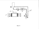
いくつかの実施態様では、本発明は又、本明細書に記載の方法を実行する連続フローシステムも提供する。例示的なシステムの概略図を図10に示す。図10では、Gはエタノールなどの溶媒に溶解した金属塩を含む反応ホッパー(チャンバ、貯槽)である。Hは高圧ポンプであり、Iは望ましい温度に加熱するキャピラリーマイクロ反応器であり、Jは粒子を検出(監視)し、ポンプ速度、温度等を調整する為にフィードバックを提供する分離器(詳細はシステムの下に示す)(例えばフォトダイオード、磁気抵抗、ホールプローブ等)であり、Kは目的の生成物を受ける収容器である。A〜Dは磁性分離器Jを表し、Aは洗浄溶媒、Bは反応混合物であり、Cは目的の生成物であり、Dは廃水流である。磁石Mは分離器のA〜C側に配置する。磁石は磁性粒子のフロー経路を引き寄せて誘導し、磁力の量(力)は分離器から離れるときに金属粒子がどのチャネル(例えば上部又は下部)に入るかを決定する。例えば磁石の方向に逸れた金属粒子は上部チャネルに流入し易くなっており、検出器Eを通り過ぎて収容器Kに入る。その逆に未反応液及び廃棄成分は全く逸れないか、或いは僅かに逸れて、分離器Jから流出するときに下部チャネルを流れ、例えばライン(導管、チャネル)Wに流入し易くなっている。図10に示された実施態様では、廃棄物の流れはリサイクルされ、反応に戻される。この例示としての系は多様な連続フロー合成工程に容易に適合できる。 In some embodiments, the present invention also provides a continuous flow system for performing the methods described herein. A schematic diagram of an exemplary system is shown in FIG. In FIG. 10, G is a reaction hopper (chamber, storage tank) containing a metal salt dissolved in a solvent such as ethanol. H is a high pressure pump, I is a capillary microreactor that heats to the desired temperature, J is a separator that detects (monitors) particles and provides feedback to adjust pump speed, temperature, etc. (Shown below the system) (e.g., photodiode, magnetoresistance, Hall probe, etc.), where K is a container that receives the desired product. A to D represent the magnetic separator J, A is the washing solvent, B is the reaction mixture, C is the desired product, and D is the wastewater stream. The magnet M is disposed on the AC side of the separator. The magnet attracts and guides the flow path of the magnetic particles, and the amount of magnetic force (force) determines which channel (eg, upper or lower) the metal particles enter when leaving the separator. For example, metal particles that deviate in the direction of the magnet are likely to flow into the upper channel, pass through the detector E and enter the container K. On the contrary, the unreacted liquid and the waste components are not deviated at all or slightly deviated to flow through the lower channel when they flow out of the separator J, and easily flow into the line (conduit, channel) W, for example. In the embodiment shown in FIG. 10, the waste stream is recycled and returned to the reaction. This exemplary system is readily adaptable to a variety of continuous flow synthesis processes.
多くの場合、システムは反応器内の条件、例えば温度、pH、混合時間、滞留時間、圧力、流速、混合速度、容積等を制御する(例えば開始、調整、及び/又は監視等を行う)コントローラーも備える。このコントローラーは通常、方法工程を実行し、更に/或いは人及びシステムの多様な構成部分から入力を受け、システムの多様な構成部分及び/又はディスプレー装置に出力を提供し、継続的に入力を監視する為に必要な指示を実行するようにプログラミングされたコンピューターである。このコンピューターはまた、関連の処理、例えば多様なデータ計算等を行うようにプログラミングされている。命令はCD、DVD、フラッシュドライブ、携帯機器等の非一時的媒体に格納し、更に/或いはインターネットを介してダウンロードしてもよい。コントローラーからの出力は例えばコンピューターモニター又は他のディスプレイスクリーン上に表示し、更に/或いは、印刷し、ハードコピーとして提供してもよい。 In many cases, the system controls the conditions in the reactor, such as temperature, pH, mixing time, residence time, pressure, flow rate, mixing speed, volume, etc. (eg, start, adjust, and / or monitor, etc.) Also equipped. The controller typically performs method steps and / or receives input from various components of the person and the system, provides output to the various components and / or display devices of the system, and continuously monitors the input. A computer programmed to execute the instructions necessary to do. The computer is also programmed to perform related processing, such as various data calculations. The instructions may be stored on a non-transitory medium such as a CD, DVD, flash drive, portable device, and / or downloaded via the Internet. The output from the controller may be displayed on a computer monitor or other display screen, for example, and / or printed and provided as a hard copy.
連続フローへのバッチ合成処理の適合
本発明のいくつかの実施態様では、スケール変更可能な湿式化学バッチ技術を連続フローでの使用に適合させる。利用される方法には、通常は、例えば「骨格」上にある1種以上の金属イオン、又は反応物に提供された支持体の核生成、その後の合金ナノ粒子を形成する骨格又は支持体上の金属の成長期が含まれる。利用する溶媒成分に応じて、得られたナノ粒子は例えばカーバイド、窒化物、ホウ化物、リン化物若しくは硫化物又はこれらの混合物となり得る。これらの粒子は、元のバルク材では見られない特性を示している。
Adapting a batch synthesis process to a continuous flow In some embodiments of the present invention, a scaleable wet chemical batch technique is adapted for use in a continuous flow. The methods utilized typically include, for example, one or more metal ions on the “framework”, or nucleation of the support provided to the reactants, followed by a skeleton or support that forms alloy nanoparticles. Includes the metal growth period. Depending on the solvent component utilized, the resulting nanoparticles can be, for example, carbide, nitride, boride, phosphide or sulfide, or mixtures thereof. These particles exhibit properties not found in the original bulk material.
1つの実施態様では、湿式化学技術はポリオール処理であり、ここでは多価アルコール(ポリオール)はグリコレートへと脱プロトン化した塩基であり、これは特に高温下で金属塩の還元及び核生成を促進する。ポリオールは溶媒や還元剤として機能し、これよって金属前駆体は還元され、グリコレートに付着した金属核を形成する。
核は従来のオストワルド成長メカニズムを経てグリコレート上で成長する。従って反応は、実質的に、脱プロトン化アルコールと目的の金属塩との間でリガンドが交換される条件下で行われる。高温では、過剰なグリコレートイオンは金属の還元を補助し、キャッピング剤としても作用する。反応温度、圧力及びアルカリ度の制御によって、還元、核生成及び反応の成長動態が制御され、目的のナノ粒子組成物が達成される。
In one embodiment, the wet chemistry technique is polyol processing, where the polyhydric alcohol (polyol) is a base deprotonated to glycolate, which reduces metal salt reduction and nucleation, particularly at elevated temperatures. Facilitate. The polyol functions as a solvent and a reducing agent, whereby the metal precursor is reduced and forms a metal nucleus attached to the glycolate.
Nuclei grow on glycolate via a conventional Ostwald growth mechanism. Thus, the reaction is substantially carried out under conditions where the ligand is exchanged between the deprotonated alcohol and the metal salt of interest. At high temperatures, excess glycolate ions assist the metal reduction and also act as a capping agent. By controlling the reaction temperature, pressure and alkalinity, reduction, nucleation and reaction growth kinetics are controlled to achieve the desired nanoparticle composition.
いくつかの例示的な実施態様では、純粋なCo2C相及び純粋なCo3C相の磁性ナノ粒子はこの方式で形成される(詳細は実施例1を参照)。 In some exemplary embodiments, pure Co 2 C phase and pure Co 3 C phase magnetic nanoparticles are formed in this manner (see Example 1 for details).
また、ポリオール処理では、金属塩を少量に分割した量を時間間隔をとってポリオールに加算添加することによって反応を実行する場合、反応させる金属塩の全量を一挙に反応混合物に添加する工程よりも優れたナノ粒子の収率及び純度の結果が得られることが分かった。理屈に捉われずに考えると、少量の金属塩の添加を繰り返す(反復)と、金属の成長は緩徐になると考えられる。緩徐な成長は、目的の相の組成、寸法及び形状での炭化物相形成の手掛かりとなり得る。金属塩を徐々に添加すると、C原子がCo構造内に再構成及び/又は拡散して夾雑物の無い目的材料が形成される為に十分な時間が得られる。従って連続フロー法はこの様な合成処理に非常に適している。 In addition, in the polyol treatment, when the reaction is performed by adding the amount obtained by dividing the metal salt into a small amount to the polyol over a time interval, it is more than the step of adding all the metal salts to be reacted to the reaction mixture all at once. It has been found that excellent nanoparticle yield and purity results are obtained. If we think without being bound by reason, it is thought that the growth of the metal becomes slow when the addition of a small amount of metal salt is repeated (repetition). Slow growth can be a clue to carbide phase formation with the composition, size and shape of the desired phase. When the metal salt is gradually added, sufficient time is obtained for the C atom to be reconstituted and / or diffused in the Co structure to form the target material free of impurities. Therefore, the continuous flow method is very suitable for such a synthesis process.
この様なナノ粒子のポリオールによる合成は通常、ポリオールと少なくとも1種の目的の金属塩とを混合する処理を含む。いくつかの実施態様では、単一種の金属塩を使用する。他の実施態様では、2種以上の金属塩を使用し、結果として混合金属組成物とのナノ粒子が生成される。前記方法で使用する為の好適なポリオールには、例えば炭素数1〜20の多様なアルコール、多様なジ又はトリアルコール;末端にルコールを有するエーテル等が挙げられるがこれらに限定されるものではない。 Such synthesis of nanoparticles with a polyol typically includes a process of mixing the polyol with at least one metal salt of interest. In some embodiments, a single type of metal salt is used. In other embodiments, two or more metal salts are used resulting in nanoparticles with the mixed metal composition. Suitable polyols for use in the above method include, but are not limited to, for example, various alcohols having 1 to 20 carbon atoms, various di- or trialcohols; ethers having a terminal alcohol. .
使用し得る金属には、例えばコバルト、鉄、ニッケル、マンガン、クロム、又はこれらの金属の合金が挙げられるがこれらに限定されるものではない。前記金属は一般的に、例えばCH3COO−、 CO3 2−、Cl−、F−、HOC(COO−)、(CH2COO−)2、C≡N−、NO3 −、NO2 −、PO4 3−及びSO4 2−、又はCO若しくはC6H5の様な有機金属などのアニオンで形成された塩の形態である。金属合金も使用可能であり、その例としては:CoNi、CoFe、NiFe、MnFe、CoNiFe、CoMnFe等が挙げられるがこれらに限定されるものではない。 Examples of metals that can be used include, but are not limited to, cobalt, iron, nickel, manganese, chromium, or alloys of these metals. The metal is generally, for example, CH 3 COO − , CO 3 2− , Cl − , F − , HOC (COO − ), (CH 2 COO − ) 2 , C≡N − , NO 3 − , NO 2 −. , PO 4 3− and SO 4 2− , or in the form of salts formed with anions such as organic metals such as CO or C 6 H 5 . Metal alloys can also be used, examples of which include, but are not limited to: CoNi, CoFe, NiFe, MnFe, CoNiFe, CoMnFe and the like.
更に他の実施態様では、1種以上の界面活性剤が前記溶媒のうち1種又は両方に含まれる。使用可能な溶媒の例には:ビス(2‐エチルヘキシル)スルホコハク酸ナトリウム(AOT)‐イソオクタン、イゲパルCo‐430(商標)などのノニルフェニルポリエトキシレート;ポリビニルピロリドン(PVP)などのポリビニルアルコール、臭化セチルトリメチルアンモニウム、及びポリエチレングリコール(PEG)が挙げられるが、これらに限定されるものではない。 In yet other embodiments, one or more surfactants are included in one or both of the solvents. Examples of solvents that can be used include: nonylphenyl polyethoxylates such as sodium bis (2-ethylhexyl) sulfosuccinate (AOT) -isooctane, Igepal Co-430 ™; polyvinyl alcohol such as polyvinylpyrrolidone (PVP), odor Examples include, but are not limited to, cetyltrimethylammonium chloride and polyethylene glycol (PEG).
反応を実行する為の条件は、ナノ粒子を形成する為に使用する金属(単数又は複数)又はそれらの金属の合金に応じて多様に変化し得る。コバルトをベースとしているナノ粒子では、反応がCo3Cに向かうように[OH−]を低度にしてもよく(例えば約0〜約0.1Mの範囲、通常約0〜約0.05M)、或いは反応がCo2Cに向かうように高度にしてもよい(例えば約0.2〜約1Mの範囲、通常約0.3〜約0.6)。他の金属では、望ましいレベルのポリオール脱プロトン化を達成する為に条件を調整する。望ましいレベルとは、好適な速度で反応を進行させるレベルを言う。例えば、Ni3Cは0M〜0.4Mの範囲、通常0.14M〜約0.2Mの範囲の[OH−]で合成できる。レベルは、例えば水酸化ナトリウム若しくはカリウム又はナトリウムエトキシド、他の好適なpH変更剤で反応混合物のpHを調整することによって調整し得る。コバルトをベースとしているナノ粒子では、反応がCo3Cに向かうように[Co+2]を広範にしてもよく(例えば約0.0001M〜溶解限度の範囲、通常約0.01〜約0.1)、或いは反応がCo2Cに向かうように低度にしてもよい(例えば約0.5mM〜約2mMの範囲、通常約1mM〜約1.5mM)。 The conditions for performing the reaction can vary widely depending on the metal (s) or alloys of the metals used to form the nanoparticles. For nanoparticles based on cobalt, the [OH − ] may be lowered so that the reaction is directed to Co 3 C (eg, in the range of about 0 to about 0.1M, usually about 0 to about 0.05M). Alternatively, the reaction may be so high that it is directed to Co 2 C (eg, in the range of about 0.2 to about 1 M, usually about 0.3 to about 0.6). For other metals, conditions are adjusted to achieve the desired level of polyol deprotonation. A desirable level refers to a level at which the reaction proceeds at a suitable rate. For example, Ni 3 C can be synthesized with [OH − ] in the range of 0M to 0.4M, usually in the range of 0.14M to about 0.2M. The level can be adjusted by adjusting the pH of the reaction mixture with, for example, sodium or potassium hydroxide or sodium ethoxide, other suitable pH modifiers. For nanoparticles based on cobalt, [Co +2 ] may be broadened so that the reaction is directed to Co 3 C (eg, in the range of about 0.0001 M to the solubility limit, usually about 0.01 to about 0.1). Or may be so low that the reaction is directed toward Co 2 C (eg, in the range of about 0.5 mM to about 2 mM, usually about 1 mM to about 1.5 mM).
又、望ましい反応速度を提供する為にポリオールを含む金属塩の混合速度を調整する。一般的に1〜2分毎にグリコール1mL当たり約0.2〜約0.4mmolの速度で金属塩を添加する。 Also, the mixing rate of the metal salt containing the polyol is adjusted to provide the desired reaction rate. Generally, the metal salt is added at a rate of about 0.2 to about 0.4 mmol per mL of glycol every 1-2 minutes.
反応は、例えば望ましい反応速度、使用する反応物、及び目的生成物等に応じて、好適な温度、例えば約180℃〜約325℃、通常約250℃〜約325℃の範囲で実行し得る。 The reaction can be carried out at a suitable temperature, for example in the range from about 180 ° C. to about 325 ° C., usually from about 250 ° C. to about 325 ° C., for example depending on the desired reaction rate, the reactants used, the desired product and the like.
超臨界流体を使用したナノ粒子の連続フロー合成
いくつかの実施態様では、超臨界流体(SCF)を使用して連続フロー合成法を実行するか、或いは遂行する。本発明の連続フロー工程の超臨界溶媒の使用によってナノ粒子の効率的な合成が可能になるだけでなく、加圧力が解放されたときに反応混合物から得たナノ粒子が有利に、急速に分離できるようにもなる。
Continuous Flow Synthesis of Nanoparticles Using Supercritical Fluid In some embodiments, a supercritical fluid (SCF) is used to perform or perform a continuous flow synthesis method. The use of supercritical solvents in the continuous flow process of the present invention not only allows for efficient synthesis of nanoparticles, but also facilitates rapid separation of nanoparticles obtained from the reaction mixture when the applied pressure is released. You can also do it.
一般的に、ナノ粒子形成反応中に連続フローシステムを加圧する以外は、合成法は連続フロー反応で上述のとおり実行する。基本的に、上述したポリオール合成に類似した方式において低圧で例えばエタノール中で反応を行う代わりに、エタノールをSCFに変換する為に十分に圧力を強める。反応の終了時、圧力を解放したところ、SCFは急速に蒸発し、合金ナノ粒子自体であるか、或いはそれを含む乾燥粉末から離脱する。言い換えれば、SCFは乾燥粉末から離脱してフラッシュ蒸発する。 Generally, the synthesis method is performed as described above in a continuous flow reaction, except that the continuous flow system is pressurized during the nanoparticle formation reaction. Basically, instead of conducting the reaction at low pressure, for example in ethanol, in a manner similar to the polyol synthesis described above, the pressure is increased sufficiently to convert ethanol to SCF. At the end of the reaction, when the pressure is released, the SCF rapidly evaporates and leaves the alloy nanoparticles themselves or from the dry powder containing them. In other words, the SCF leaves the dry powder and flash evaporates.
いくつかの実施態様では、使用する超臨界流体は:アルコールを含み、その例としては:エタノール、プロパノール、ブタノール、エトキシエタノール等;上記で列挙した様な多様なグリコール;液体二酸化炭素;及びアセトニトリル等が挙げられるがこれらに限定されるものではない。基本的に、目的の金属塩が溶解し、連続フロー反応器中で可能な圧力下でSCFに成り得る液体ならどの様なものでも使用可能である。好ましくは、これらの試薬は安価で都合良く、反応混合物からの除去時に容易に再捕捉され、再使用できるようになる。したがって、廃棄物処理が最小限になり、更にナノ粒子の製造コストを削減し、環境上の利点をもたらす。 In some embodiments, the supercritical fluid used includes: alcohols, for example: ethanol, propanol, butanol, ethoxyethanol, etc .; various glycols as listed above; liquid carbon dioxide; and acetonitrile, etc. However, it is not limited to these. In principle, any liquid can be used that dissolves the metal salt of interest and can become SCF under the pressure possible in a continuous flow reactor. Preferably, these reagents are inexpensive and convenient and can be easily recaptured and reused upon removal from the reaction mixture. Thus, waste disposal is minimized, further reducing the manufacturing costs of the nanoparticles and providing environmental benefits.
使用できる金属には「連続フローへのバッチ合成処理の適合」と題する項で述べたものが挙げられる。 Metals that can be used include those mentioned in the section entitled “Adaptation of batch synthesis processes to continuous flow”.
コア‐シェルナノ粒子
いくつかの実施態様では、本明細書に述べたとおり合成したナノ粒子はコア‐シェルナノ粒子である。コアシェルナノ粒子は、1種の材料のコア、及び別種の材料のコーティングシェルを含む構成ナノ粒子である。コアの直径は例えば約1〜100nmであり、シェルの厚さは約1〜100nmである。1つの実施態様では、コアシェル粒子は鉄/酸化鉄粒子であり、即ち粒子の表面は酸化され、よって粒子は酸化鉄に被覆される。
Core-shell nanoparticles In some embodiments, nanoparticles synthesized as described herein are core-shell nanoparticles. Core shell nanoparticles are constituent nanoparticles that include a core of one material and a coating shell of another material. The diameter of the core is, for example, about 1 to 100 nm, and the thickness of the shell is about 1 to 100 nm. In one embodiment, the core-shell particles are iron / iron oxide particles, i.e. the surface of the particles is oxidized, so that the particles are coated with iron oxide.
本発明の連続フローマイクロ流体反応器は商業化を可能にするようにこのタイプのナノ粒子を大量に提供するのに非常に適している。 The continuous flow microfluidic reactor of the present invention is very suitable for providing large quantities of this type of nanoparticles to allow commercialization.
この技術の応用の例
本発明の磁性ナノ材料は、永久磁石の製作など多くの用途に限定することなく使用可能である。従って1つの実施態様では、本発明は本明細書に記載の磁性ナノ粒子から形成された(即ち、磁性ナノ粒子を含むか、或いは組み込んでいる)永久磁石、即ち、レアアースメタルは含まず(それらは「非レアアース」永久磁石用である)、多くの異なる方法で使用可能な永久磁石を提供する。例えばそれらは電動機(例えばプラグインハイブリッドその他の電気自動車)、直接駆動風力タービン電力系統、多様なエネルギー貯蔵システム(例えばフライホイール)、磁気記録媒体(例えばハードディスクドライブ、フロッピーディスク、磁気テープ等)、磁性分離装置に組み込んでもよく、又、他の製品、例えば玩具中に組み込んでもよく、締結装置、冷蔵庫用磁石等としても組み込める。
Examples of application of this technology The magnetic nanomaterial of the present invention can be used without being limited to many applications such as production of permanent magnets. Thus, in one embodiment, the present invention does not include permanent magnets (ie, rare earth metals) that are formed from (ie, contain or incorporate) magnetic nanoparticles described herein (ie, rare earth metals). For permanent magnets) provides permanent magnets that can be used in many different ways. For example, they are electric motors (eg plug-in hybrids and other electric vehicles), direct drive wind turbine power systems, various energy storage systems (eg flywheels), magnetic recording media (eg hard disk drives, floppy disks, magnetic tapes, etc.), magnetic It may be incorporated into a separation device, or may be incorporated into another product, such as a toy, and may be incorporated as a fastening device, a refrigerator magnet, or the like.
特に、本発明は、本発明の永久磁石を含む電動機を提供する。電動機は様々な用途に使用可能である。 In particular, the present invention provides an electric motor including the permanent magnet of the present invention. The electric motor can be used for various purposes.
他の実施態様では、本発明は軟磁石を提供する。本発明の軟磁石は好適な装置又は好適な用途であればどのようなものにも使用できる。 In another embodiment, the present invention provides a soft magnet. The soft magnet of the present invention can be used in any suitable device or any suitable application.
実施例1.交換結合した炭化コバルトナノ粒子の溶液処理集合を介した非レアアース高性能永久磁石
レアアース永久磁石は風力タービン及び電気自動車モーターなどのクリーンテクノロジー用途に大きな影響力を有する1。しかし、米国へのレアアース商品に関する輸入の権利が規制されているので、レアアース永久磁石はメーカーに対して次第に高額なものとなってきている。類似の、又は増強されたエネルギー生成物と共に、レアアースフリー永久磁石などの代替的資源は集中的に研究対象となりつつある1,2。近年、混合相炭化コバルトナノ粒子が強化磁性を有することが分かり、レアアース元素が不足しているのでクリーンエネルギー技術での使用に向けて非常に関心が集まっている3,4。しかし、磁性能を十分に最適化する為に、ナノ粒子を含む相をより深く理解し、制御する必要が依然としてある。本明細書では、本発明者らが湿式化学技術を介して処理した純粋相Co3C及びCo2Cナノ粒子の合成及び特徴化を報告している。磁性及び熱特性を研究することによって、形成のメカニズム及び磁性の起源についての詳細な知識を明らかにした。磁性について各相が有する効果を判定すれば、それらのエネルギー生成物を現代技術の磁石に匹敵するよう効果的に促進することにより最新式の永久磁石が得られるであろう。
Example 1. Non-rare earth high performance permanent magnets via solution-treated assembly of exchange-coupled cobalt carbide nanoparticles Rare earth permanent magnets have a significant impact on clean technology applications such as wind turbines and electric vehicle motors 1 . However, because the right to import rare earth products into the United States is regulated, rare earth permanent magnets are becoming increasingly expensive for manufacturers. Alternative resources such as rare earth-free permanent magnets, along with similar or enhanced energy products, are intensively studied 1, 2 . Recently, I found that mixed phase cobalt carbide nanoparticles having enhanced magnetism, are very attention has focused towards the use of clean energy technology since rare earth elements are missing 3,4. However, there is still a need to better understand and control the phase containing the nanoparticles in order to fully optimize the magnetic performance. Here we report the synthesis and characterization of pure phase Co 3 C and Co 2 C nanoparticles processed via wet chemistry techniques. By studying magnetic and thermal properties, detailed knowledge about the mechanism of formation and the origin of magnetism was revealed. Once the effect of each phase on magnetism is determined, a state-of-the-art permanent magnet will be obtained by effectively promoting their energy products to match modern magnets.
永久磁石は多数のエネルギー関連用途において重要な構成要素であり、そこでは、通常最大エネルギー生成物(BH)maxを介して示される磁石の磁気エネルギー密度の増加が、装置全体の効率が高まる(例えば、電動機の容量対電力比)。1960年代及び1970年代のレアアース永久磁石の開発以来、合成処理及び異方性制御能を変えることで(BH)maxは僅かに進歩してきている。しかし、増強されたエネルギー生成物を有する新規な材料を発見することには限界がある1,2。非レアアース永久磁石の最後の主要な進展はAlNiCo磁石の開発をしていた1930年代半ばに遡るが、それ以来、(BH)maxが多少改変されたことしか報告されていない2。AlNiCoよりも性能が優れた、又、最良のレアアース永久磁石に対してさえ性能が優れている可能性のある非レアアース永久磁石材料の新たなクラスに、近年の炭化コバルトナノ粒子の探索は門戸を開いている。CoxCナノ粒子の合成は湿式化学技術であるポリオール処理を利用して達成され、ここでは、コバルト前駆体の塩を多価アルコール(ポリオール)に溶解し、溶媒の沸点に近い高温(250〜325℃)まで加熱する。ポリオールはこれらの高温でその反応性が最も高く、溶媒、キャッピング剤及び還元剤として作用する。この湿式化学アプローチを利用すると、相純粋炭化物を生成するように磁性を調整することが可能になり、それによって新規な高エネルギー生成物の永久磁石が作り出される。 Permanent magnets are an important component in many energy-related applications, where an increase in the magnet's magnetic energy density, usually indicated via the maximum energy product (BH) max , increases the overall efficiency of the device (eg, , Motor capacity to power ratio). Since the development of rare earth permanent magnets in the 1960s and 1970s, (BH) max has advanced slightly by changing the synthesis process and anisotropic controllability. However, there is a limit to find new materials with enhanced energy product 1,2. The last major development of non-rare earth permanent magnets dates back to the mid 1930s when AlNiCo magnets were being developed, but since then only (BH) max has been reported with some modifications 2 . The recent search for cobalt carbide nanoparticles is a new class of non-rare earth permanent magnet materials that have better performance than AlNiCo and may even outperform even the best rare earth permanent magnets. is open. The synthesis of Co x C nanoparticles is achieved by using a polyol process, which is a wet chemical technique, in which a salt of a cobalt precursor is dissolved in a polyhydric alcohol (polyol) and is heated to a high temperature (250- 325 ° C.). Polyols are most reactive at these high temperatures and act as solvents, capping agents and reducing agents. Utilizing this wet chemistry approach, it is possible to tailor the magnetism to produce phase pure carbide, thereby creating a new high energy product permanent magnet.
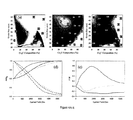
代表的な反応では、水酸化カリウムをテトラエチレングリコール(TEG)に溶解し、275℃まで加熱する。溶液がその温度に到達すると、コバルト塩を高温溶液に、10回に分けて徐々に20分間添加する。コバルト塩を1回のみ添加した実験では、得られた粒子は金属コバルト相と炭化コバルト相との組成となる。コバルト塩を徐々に添加すると成長工程が劇的に遅くなり、炭素がコバルト構造に組み込まれ、純粋な炭化物相ナノ粒子が形成される。純粋Co2C及びCo3C炭化物の相形成の複雑な制御は、TEG溶液中の水酸化物濃度を変えることによって完成される。基本環境では、多様な鎖長のポリエチレングリコール(PEG)を生成する濃縮反応を介してポリオールは重合するとされている。水酸化物濃度が高まれば、PEG鎖長が長くなり、核生成動態が変化し、コバルト核(α‐Co又はβ‐Co)のいずれか一方の形態が生成される。低い水酸化物濃度では、核生成中に動力学的生成物α‐Co(六方稠密構造、HCP)が形成され、一方、高い濃度では、熱力学的生成物β‐Co(面心立方構造、FCC)が形成される5,6。核形成されたコバルトの初期の構造はその後、最終的な炭化物相形成を決定する;α‐CoはCo3Cを形成し、一方、α‐Coとβ‐Coとの混合物はCo2Cを形成する。X線回折データ及び構造の改質に従えば、Co2Cの試料の算出した格子定数は、a=4.45Å、b=4.37Å、及びc=2.90Å(空間群Pnnm)であり、Co3Cの格子定数はa=5.02Å、b=6.73Å、及びc=4.44Å(空間群Pnma)である(XRDスキャンは補足情報S1において見られる)。これらの格子定数はバルクCoxC粒子の格子定数と一致する7。 In a typical reaction, potassium hydroxide is dissolved in tetraethylene glycol (TEG) and heated to 275 ° C. When the solution reaches that temperature, the cobalt salt is gradually added to the hot solution in 10 portions over 20 minutes. In the experiment in which the cobalt salt is added only once, the obtained particles have a composition of a metallic cobalt phase and a cobalt carbide phase. Gradual addition of cobalt salt dramatically slows the growth process, incorporating carbon into the cobalt structure and forming pure carbide phase nanoparticles. Complex control of the phase formation of pure Co 2 C and Co 3 C carbide is accomplished by changing the hydroxide concentration in the TEG solution. In the basic environment, polyols are said to polymerize through a concentration reaction that produces polyethylene glycol (PEG) of various chain lengths. As the hydroxide concentration increases, the PEG chain length increases and the nucleation kinetics changes, producing either form of cobalt nuclei (α-Co or β-Co). At low hydroxide concentrations, the kinetic product α-Co (hexagonal dense structure, HCP) is formed during nucleation, while at high concentrations, the thermodynamic product β-Co (face centered cubic structure, FCC) is formed 5,6 . The initial structure of the nucleated cobalt then determines the final carbide phase formation; α-Co forms Co 3 C, while a mixture of α-Co and β-Co forms Co 2 C. Form. According to the modification of the X-ray diffraction data and structure, the calculated lattice constants of the sample of Co 2 C are a = 4.45 Å, b = 4.37 Å, and c = 2.90 Å (space group Pnnm). , Co 3 C have lattice constants of a = 5.02Å, b = 6.73 及 び, and c = 4.44Å (space group Pnma) (XRD scan is found in the supplemental information S1). These lattice constants are consistent with the lattice constants of bulk Co x C particles 7 .
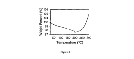
高温X線回折(ETXRD)は更に金属構造と炭化物相とのこの相関関係を裏付けた(図1)。初期では、温度が25℃〜250℃に上昇すると、富炭素Co2Cは分解し、α及びβ‐Co両方の混合物を形成する。Co3Cでは、炭素含有量が減少し、結果として325℃の高めの分解温度になる。炭化物格子への崩壊が少ないので、α‐Coのみが形成される。金属コバルト相と炭化物相との関連性は興味深いが、それだけでは炭化コバルト系の形成メカニズムは殆ど解明されることはない。 High temperature X-ray diffraction (ETXRD) further confirmed this correlation between metal structure and carbide phase (FIG. 1). Initially, as the temperature rises from 25 ° C. to 250 ° C., the carbon-rich Co 2 C decomposes and forms a mixture of both α and β-Co. With Co 3 C, the carbon content decreases, resulting in a higher decomposition temperature of 325 ° C. Only α-Co is formed because there is less decay into the carbide lattice. Although the relationship between the metallic cobalt phase and the carbide phase is interesting, the formation mechanism of the cobalt carbide system is hardly elucidated by itself.
炭化コバルトナノ粒子の形成に取り組んだ研究は殆ど無いが、ニッケルを触媒としたFisher‐Tropsch合成中での炭化ニッケルの形成は広く研究されている。ニッケルは結晶化してコバルトの類似金属や炭化物同素体になり、よって炭化ニッケルの形成は、炭化コバルト系まで拡大することができる。TEGの高温ではFisher‐Tropsch合成で報告されたものと類似の炭化物サイクルに従って炭素化が起こる傾向にある8〜12。金属コバルトナノ粒子が核形成をするにつれ、それらはグリコレートの分解を触媒し、ナノ粒子表面に炭素を形成する。これらの表面に炭素原子が存在する為、表面拡散が起こり、金属コバルトナノ粒子の構造が変わる。ETXRDデータに示す様に、炭化物相の形成は、核形成中の金属コバルト相、及び表面炭素の量に依存している13。Co3Cはα‐Co表面の窪んだ部位に充填されている炭素から形成される。Co2Cでは、α‐Co(001)及びβ‐Co(111)平面でp4g clock部位が再構成される9,14。p4g表面再構成を誘導する為に必要な炭素の増加は、ETXRD試験に見られる2相粒子系に起因する欠陥の結果である13。繰返し加算によって成長速度が低下する為に炭素は表面層内に僅かに拡散しながら、炭素は連続的に取り込まれ、完全に炭化物へと変換される。コバルト前駆体が即座に導入されると、コバルトは急速に成長する。炭素形成がコバルトの成長よりも緩やかであるので、多相金属/炭化物粒子が形成される。しかし、コバルト前駆体を繰り返し添加することによって、成長が段階的に起こり、炭素が完全に取り込まれ、純粋な炭化物相が形成される。 Although few studies have addressed the formation of cobalt carbide nanoparticles, the formation of nickel carbide during the Fischer-Tropsch synthesis catalyzed by nickel has been extensively studied. Nickel crystallizes into cobalt-like metals and carbide allotropes, so the formation of nickel carbide can be extended to cobalt carbide systems. At high temperatures of TEG, carbonization tends to occur according to a carbide cycle similar to that reported in the Fisher-Tropsch synthesis 8-12 . As the metallic cobalt nanoparticles nucleate, they catalyze the decomposition of glycolate and form carbon on the nanoparticle surface. Since carbon atoms exist on these surfaces, surface diffusion occurs and the structure of the metal cobalt nanoparticles changes. As shown in the ETXRD data, the formation of the carbide phase depends on the amount of metallic cobalt phase and surface carbon during nucleation 13 . Co 3 C is formed from carbon filled in a depressed portion of the α-Co surface. In Co 2 C, α-Co ( 001) and β-Co (111) p4g clock site reconstructed plane 9,14. The increase in carbon required to induce p4g surface reconstruction is the result of defects due to the two-phase particle system found in the ETXRD test 13 . Since the growth rate is reduced by repeated addition, the carbon is continuously taken in while being slightly diffused in the surface layer, and is completely converted into carbide. If the cobalt precursor is introduced immediately, the cobalt grows rapidly. Since carbon formation is slower than cobalt growth, multiphase metal / carbide particles are formed. However, by repeatedly adding the cobalt precursor, growth occurs in stages, carbon is completely incorporated and a pure carbide phase is formed.
炭化コバルトの合成に関する先行の報告では、炭素は金属ナノ粒子上のグラファイト状炭素層として認識されている15〜18。本研究では、表面炭素の構造を判定する為に、X線光電子分光法によって炭化物粒子の表面を調べた。図2(a,b)に示すCo3C及びCo2Cの炭素C1sスキャンは3つの炭素種:288.5eVのC=O、286.3eVのC‐O、及び284.7eVのC‐Cを示している。C‐O及びC=O種は表面上のグリコレートの存在を暗示している19。2つの相を比較すると、高pHのグリコレートの酸化によって、Co2CのC=Oの比率は高い。興味深いことに、Co3C又はCo2CのXPSスキャンにおいて化合炭素は同定されなかった9,11。しかし、図2(挿入図)における空間が満たされたモデルを見ると、Co3C及びCo2C両方の表面に微量の化合炭素が存在している。グリコレート層とカップリングした表面炭素の濃度が低いことは化合炭素の確実な同定が不可能であることを明らかにしている。又、不活性化したコバルトをベースとしたFischer‐Tropsch触媒のXPS試験により、大量の断片化された炭化水素、及び吸着されたC‐O種が同定される。化合炭素はH2における還元による表面炭素の除去中でのみ見られる10。 In previous reports on the synthesis of cobalt carbide, carbon is recognized as a graphitic carbon layer on metal nanoparticles 15-18 . In this study, the surface of carbide particles was examined by X-ray photoelectron spectroscopy to determine the structure of surface carbon. The carbon C1s scan of Co 3 C and Co 2 C shown in FIG. 2 (a, b) shows three carbon species: 288.5 eV C═O, 286.3 eV C—O, and 284.7 eV C—C. Is shown. The C—O and C═O species imply the presence of glycolate on the surface 19 . Comparing the two phases, the ratio of C 2 O in Co 2 C is high due to oxidation of high pH glycolate. Interestingly, no compound carbon was identified in Co 3 C or Co 2 C XPS scans 9,11 . However, looking at the model in which the space in FIG. 2 (inset) is filled, there is a trace amount of compound carbon on the surface of both Co 3 C and Co 2 C. The low concentration of surface carbon coupled to the glycolate layer reveals that compound carbon cannot be reliably identified. XPS tests of deactivated cobalt-based Fischer-Tropsch catalysts also identify large amounts of fragmented hydrocarbons and adsorbed CO species. Compound carbon is only seen during removal of surface carbon by reduction in H 2 10 .
合成Co2C及びCo3C粒子の平均粒子径は約300nm(図3(a))である。Co2C及びCo3C粒子は両方とも同じ直径の球状である(図3(b,c))。粒子表面の高解像度TEM画像によってグリコレート層と、大きい集塊に付着した微細な晶子の存在が明らかになっている(図3(b〜d))。この多結晶集合体はSAED及びXRDScherrer分析からも確認された。画像のフーリエ変換によってCo3Cの格子定数a=5.05A及びc=4.48Aが確認され(図3(e,f))、これらはX線回折から得られた値と同等である。 The average particle diameter of the synthetic Co 2 C and Co 3 C particles is about 300 nm (FIG. 3A). Co 2 C and Co 3 C particles are both spherical with the same diameter (FIG. 3 (b, c)). The high-resolution TEM image of the particle surface reveals the presence of a glycolate layer and fine crystallites attached to large agglomerates (FIGS. 3 (b-d)). This polycrystalline aggregate was also confirmed by SAED and XRD DScher analysis. Co 3 C lattice constants a = 5.05A and c = 4.48A are confirmed by Fourier transform of the image (FIG. 3 (e, f)), which are equivalent to the values obtained from X-ray diffraction.
純粋相Co2C及びCo3Cの合成により、各相に本来備わっている磁性を正確に同定することができる。2つの純粋相と同様、多様な相比から成るCoxC粒子も特徴的であった。単相Co2Cは飽和保磁力が低く(450Oe)、磁化が低く(13emu/g)、一方、単相Co3Cは飽和保磁力が高く(1.6kOe)、飽和磁化が高い(55emu/g)ことが分かった(図4(a,b))。又、単相Co3C粒子の(BH)maxは高い(Co3Cでは1.5 MGOe、対してCo2Cでは0.1MGOe)(図4(c))1。Co3Cの高飽和保磁力の原因は静磁気相互作用にあると考えられる(図4(e))。低磁界強度では、Co3C系の磁性は、存在する超常磁性成分からの双極子‐双極子相互作用によって支配される。Co2Cはその系内にドープされると、双極子‐双極子相互作用は交換結合に取って代わられる(図4(e))。Co2C組成物を80%以上に増加させると、交換結合の程度は低下し、飽和保磁力が減少する。CoxC粒子では粒度も(BH)max値に影響を与え、粒度が小さいと交換結合が増加する20〜22。 By synthesizing the pure phases Co 2 C and Co 3 C, the inherent magnetism of each phase can be accurately identified. Similar to the two pure phases, Co x C particles with various phase ratios were also characteristic. Single phase Co 2 C has low coercivity (450 Oe) and low magnetization (13 emu / g), while single phase Co 3 C has high coercivity (1.6 kOe) and high saturation magnetization (55 emu / g). g) was found (Fig. 4 (a, b)). In addition, (BH) max of single-phase Co 3 C particles is high (1.5 MGOe for Co 3 C and 0.1 MGOe for Co 2 C) (FIG. 4C) 1 . The cause of the high coercivity of Co 3 C is considered to be a magnetostatic interaction (FIG. 4 (e)). At low magnetic field strength, the Co 3 C-based magnetism is dominated by dipole-dipole interactions from existing superparamagnetic components. When Co 2 C is doped into the system, the dipole-dipole interaction is replaced by exchange coupling (FIG. 4 (e)). When the Co 2 C composition is increased to 80% or more, the degree of exchange coupling decreases and the coercivity decreases. In Co x C particles, the particle size also affects the (BH) max value, and exchange coupling increases 20-22 when the particle size is small.
第1原理理論研究によって、Co2C及びCo3C相と関連した磁気モーメント及び磁気結晶異方性エネルギー(MAE)を試験した。方法の項で正確な理論的方法が分かる。純粋β‐Coでは、1原子当たりの計算上の磁気モーメント1.86μbは、実験上のモーメント1.81μbに近似している。又、理論研究によって、Co2CもCo3Cも金属性であり、モーメントはそれぞれCo2Cでは1.0μb/原子、Co3Cでは1.65μb/原子であることが示されている。本発明者らの発見は、Co2CよりもCo3Cでの磁気モーメントで実験的に観察された増加とよく一致している。バルクCoは軟磁性材料(飽和保磁力は150Oe未満で低い)であり、本発明者らのMAE計算は実際、[100]の方向に沿った容易軸を示す。[110]及び[111]の方向では、研究は、それぞれ0.0092及び0.0161eV/原子のCo原子当たりのMAEを示している。Co2C相では、容易軸は[001]方向に沿い、[111]に沿うMAE/原子は0.124eV/Co2Cである。しかし、Co3C相は[100]容易軸を有するがMAEは他の方向に沿って0.15〜0.19meV/Co3Cへと増加するのでCo3C相は独特である。前記化合物の単軸異方性のおかげで飽和保磁力が高まる。 A first-principles theoretical study examined the magnetic moment and magnetocrystalline anisotropy energy (MAE) associated with the Co 2 C and Co 3 C phases. The exact theoretical method can be found in the method section. For pure β-Co, the calculated magnetic moment of 1.86 μb per atom approximates the experimental moment of 1.81 μb. Further, by theoretical studies, Co 2 C is also Co 3 C also metal, have shown that the moment each Co 2 C In 1.0Myubi / atom, a Co 3 C In 1.65Myubi / atom. Our findings are in good agreement with the experimentally observed increase in magnetic moments in Co 3 C rather than Co 2 C. Bulk Co is a soft magnetic material (coercivity is low at less than 150 Oe) and our MAE calculation actually shows an easy axis along the [100] direction. In the [110] and [111] directions, studies show MAE per Co atom of 0.0092 and 0.0161 eV / atom respectively. In the Co 2 C phase, the easy axis is along the [001] direction, and the MAE / atom along [111] is 0.124 eV / Co 2 C. However, Co 3 C phase has a [100] axis of easy MAE since increases to 0.15~0.19meV / Co 3 C along other directions Co 3 C phase is unique. The coercivity increases due to the uniaxial anisotropy of the compound.
要約すれば、改変ポリオール処理を利用し、純粋相Co2C及びCo3Cナノ粒子を合成した。炭化物相の分析を経て、形成のメカニズムが包括的に理解された。初めに、水酸化物濃縮によるCoxC相の制御、並びに他の必要な合成パラメータを報告する。Co3C及びCo2Cの磁性の特徴化及び第1原理理論研究によって、各相に本来備わっている磁性が同定された。個々のモチーフの寸法及び組成の調整によってCoxCナノ粒子のエネルギー生成物が増加できることを各炭化物相の現在公知の磁性によって予測する。出発原料と高エネルギー生成物のコストが低ければ、CoxCは多くの技術及び産業用途で現在の永久磁石に取って代わる魅力ある代替物となるであろう。 In summary, the modified polyol treatment was utilized to synthesize pure phase Co 2 C and Co 3 C nanoparticles. Through the analysis of the carbide phase, the formation mechanism was comprehensively understood. First, we report the control of the Co x C phase by hydroxide concentration, as well as other necessary synthesis parameters. The magnetic characterization of Co 3 C and Co 2 C and first-principles theoretical studies identified the intrinsic magnetism of each phase. It is predicted by the currently known magnetism of each carbide phase that the energy product of Co x C nanoparticles can be increased by adjusting the size and composition of the individual motifs. If the cost of starting materials and high energy products is low, Co x C would be an attractive alternative to replace current permanent magnets in many technical and industrial applications.
方法
代表的な実験では、テトラエチレングリコール(TEG)を磁気的に、又は機械的に撹拌し、蒸留条件下で様々な量のKOHで275℃まで加熱した。溶液が目的の温度に達すると、10回に分けた分の総量で2.0×10⁻⁴モルのCo(Ac)2‐4H2Oを2分間隔で個々に添加した。コバルト前駆体の最終添加後、反応をその温度で15分間維持した後、1時間、室温まで冷却した。その後溶液を遠心分離し、数回洗浄し、磁気的に分離した。初めにエタノールで数回洗浄し、その後5%HNO3のエタノール溶液を最終洗浄として使用した。その後、回収した粒子を真空オーブンで乾燥した。
In a typical experiment, tetraethylene glycol (TEG) was stirred magnetically or mechanically and heated to 275 ° C. with various amounts of KOH under distillation conditions. When the solution reached the desired temperature, 2.0 × 10 −4 moles of Co (Ac) 2 -4H 2 O was added individually at 2 minute intervals in a total of 10 portions. After the final addition of the cobalt precursor, the reaction was maintained at that temperature for 15 minutes and then cooled to room temperature for 1 hour. The solution was then centrifuged, washed several times and magnetically separated. Initially washed several times with ethanol, then 5% HNO 3 in ethanol was used as the final wash. Thereafter, the collected particles were dried in a vacuum oven.
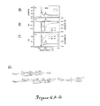
X線回折(XRD)スキャン像をPanalyticalのX’Pert Pro MPDシリーズ回折計を使用して収集し、Cu Kα放射(λ=0.154056Å)はθ〜2θの幾何学的配置にある。高温X線回折(ETXRD)では、Anton Paar HTK−1200N高温カメラを、TCU‐1000温度制御装置と共に使用した。ETXRDスキャン像を流動N2雰囲気下で収集した。熱膨張を補正する為に、各温度でダイレクトビーム二分法を利用して試料高さを調整した。XRD分析はX’Pert Highscore Plusソフトウエアを使用して行った。粒度を判定する為に、XRDスキャン像を最初にバックグラウンド補正した。その後それらをならし、各ピークのFWHMをProfitアルゴリズムを使用して判定した。その後、Co2C(111)ピーク及びCo3C(210)ピークのFWHMを使用してScherrer式を適用した。120kVで稼働するZeiss Libra120及び200kVで稼働するJEOL2100LaB6を用いて電子顕微鏡(TEM)試験を行った。粒子をエタノールに懸濁し、5分間超音波処理することによってTEM用試料を調製した。その後、その少量を超薄炭素TEMグリッド上でピペッティングし、画像化に先立って溶媒を乾燥させた。最大印加磁場10キロエルステッド(kOe)でLakeshore VSMを用いて磁性を判定した。印加磁場の関数として、等温残留磁化(IRM)及び直流脱磁(DCD)のプロットを収集した。IRMプロットでは、零磁場で磁化を測定した後、勾配を与えてΔHにして零磁場に戻した。次いで、磁化を測定しΔHの増加工程を繰り返した。DCDプロットでは、初めに試料を負磁場で飽和させ、零磁場に戻した。その後、IRMプロットで説明した通りに磁化を測定した。IRM及びDCDプロットのΔHは両方とも20Oeであった。集束単色Al Kα X線(1486.6eV)光源を備えるThermo Scientific ESCALAB 250マイクロプローブ及び6元素多チャンネル検出器を備える180°半球状分析器でX線光電子分光法(XPS)を行った。入射X線ビームは試料に対して45°非法線であり、一方、X線光電子検出器は試料に対して法線であった。角度分解実験は正常角度から4°刻みで、ピーク強度が消滅するまで行った。試料を金クラスタでスパッタし、Au 4Fピークが83.95eVになるように結合エネルギーを補正した。一定分析器エネルギー(CAE)モードではスポットサイズが500μmである広域磁気レンズを20eVのパスエネルギーで利用した。0.100eVの刻み幅の感度に基づいて1領域当たり5〜20枚のスキャン像を収集した。粉末化した試料をインジウム箔に押し付け、両面導電性カーボンテープを用いて試料ホルダーに固定した。
X-ray diffraction (XRD) scan images are collected using a Panaritical X'Pert Pro MPD series diffractometer, with Cu Kα radiation (λ = 0.154,056Å) in a θ-2θ geometry. For high temperature X-ray diffraction (ETXRD), an Anton Paar HTK-1200N high temperature camera was used with a TCU-1000 temperature controller. ETXRD scan images were collected under flowing N 2 atmosphere. In order to correct thermal expansion, the sample height was adjusted at each temperature using the direct beam bisection method. XRD analysis was performed using X'Pert Highscore Plus software. To determine the particle size, the XRD scan image was first background corrected. They were then smoothed and the FWHM of each peak was determined using the Profit algorithm. The Scherrer equation was then applied using the FWHM of the Co 2 C (111) peak and the Co 3 C (210) peak. An electron microscope (TEM) test was performed using Zeiss Libra 120 operating at 120 kV and JEOL 2100 LaB 6 operating at 200 kV. Samples for TEM were prepared by suspending the particles in ethanol and sonicating for 5 minutes. Thereafter, a small amount was pipetted on an ultra-thin carbon TEM grid and the solvent was dried prior to imaging. Magnetism was determined using a Lakeshoe VSM with a maximum applied magnetic field of 10 kiloOersted (kOe). Plots of isothermal remanent magnetization (IRM) and direct current demagnetization (DCD) were collected as a function of applied magnetic field. In the IRM plot, magnetization was measured in a zero magnetic field, and then a gradient was given to ΔH to return to the zero magnetic field. Next, the magnetization was measured and the process of increasing ΔH was repeated. In the DCD plot, the sample was first saturated with a negative magnetic field and returned to zero magnetic field. Thereafter, the magnetization was measured as described in the IRM plot. The ΔH for both the IRM and DCD plots was 20 Oe. X-ray photoelectron spectroscopy (XPS) was performed on a 180 ° hemispherical analyzer equipped with a
Vienna Ab initio Simulation Package(VASP)を用いて密度関数フレームワーク内で第1原理研究を行った23,24。電子‐イオン相互作用をモデリングする為に投影器拡大波法を利用し、Co及びCの価電子状態はそれぞれ[Ar]3d84s1及び[He]2s22p2電子配置によって説明した25。複合機能的B3LYPを使用して交換相関寄与を組み込んだ26。U値が4.0eVであるGGA+Uアプローチにおいて、本発明者らはPerdew、Burke及びEmzerofが提案した一般化傾斜汎関数も試みたところ、同様の結果が見られた27,28。エネルギーカットオフ値が400eVの平面波基盤を使用し、5×5×5区画のMokhorst‐Packスキームを利用し、電荷密度を構成する為の特別な極限点を形成した29。スピン‐軌道カップリングからの寄与を利用して磁気結晶異方性エネルギー(MAE)を計算した。Co2C及びCo3C相では、X線回折に基づく構造を更に最適化した。バルクCoで補助計算も行った。 First-principles studies were performed within the density function framework using the Vienna Ab initio Simulation Package (VASP) 23,24 . The projector extended wave method was used to model the electron-ion interaction, and the valence states of Co and C were explained by the [Ar] 3d 8 4s 1 and [He] 2s 2 2p 2 electron configurations 25, respectively . A composite functional B3LYP was used to incorporate exchange correlation contributions 26 . In GGA + U approach is U value is 4.0 eV, the present inventors have Perdew, was also tried generalized gradient functionals Burke or Emzerof proposed, similar results were observed 27 and 28. Using a plane wave base with an energy cut-off value of 400 eV, a 5 × 5 × 5 compartment Mokhorst-Pack scheme was used to form special extreme points for constructing charge density 29 . The magnetocrystalline anisotropy energy (MAE) was calculated using the contribution from spin-orbit coupling. For the Co 2 C and Co 3 C phases, the structure based on X-ray diffraction was further optimized. Auxiliary calculations were also performed with bulk Co.
(実施例1の参考文献)
1 Sugimoto, S. Current status and recent topics of rare−earth permanent magnets. Journal of Physics D−Applied Physics 44, 11, doi:06400110.1088/0022−3727/44/6/064001.
2 Gutfleisch, O. et al. Magnetic Materials and Devices for the 21st Century: Stronger, Lighter, and More Energy Efficient. Adv. Mater. (Weinheim, Ger.) 23, 821−842, doi: 10.1002/adma.201002180.
3 Harris, V. G. et al. High coercivity cobalt carbide nanoparticles processed via polyol reaction: a new permanent magnet material. Journal of Physics D−Applied Physics 43, 7, doi: 16500310.1088/0022−3727/43/16/165003 (2010).
4 Zhang, Y. et al. Controlled synthesis and magnetic properties of hard magnetic CoxC (x=2, 3) nanocrystals. J. Magn. Magn. Mater. 323, 1495−1500 (2011).
5 Chakroune, N., Viau, G., Ricolleau, C, Fievet− Vincent, F. & Fievet, F. Cobalt−based anisotropic particles prepared by the polyol process. J. Mater. Chem. 13, 312−318, doi:10.1039/b209383a (2003).
6 Hinotsu, T., Jeyadevan, B., Chinnasamy, C. N., Shinoda, K. & Tohji, K. Size and structure control of magnetic nanoparticles by using a modified polyol process. J. Appl. Phys. 95, 7477−7479, doi: 10.1063/1.1688534 (2004).
7 Pearson, W. B. Handbook of Lattice Spacings and Structures of Metals. Vol. 2 (Pergamon Press, 1967).
8 Cheng, J. et al. Density Functional Theory Study of Iron and Cobalt Carbides for Fischer−Tropsch Synthesis. J. Phys. Chem. C 1 14, 1085−1093, doi: 10.1021/jp908482q.
9 Tan, K. F., Xu, J., Chang, J., Borgna, A. & Saeys, M. Carbon deposition on Co catalysts during Fischer−Tropsch synthesis: A computational and experimental study. J. Catal. 274, 121−129, doi:10.1016/j.jcat.2010.06.008.
10 Beitel, G. A., de Groot, C. P. M., Oosterbeek, H. & Wilson, J. H. A Combined in−Situ PM−RAIRS and Kinetic Study of Single−Crystal Cobalt Catalysts under Synthesis Gas at Pressures up to 300 mbar. The Journal of Physical Chemistry B 101, 4035−4043 (1997).
11 Xiong, J. et al. The formation of Co2C species in activated carbon supported cobalt−based catalysts and its impact on Fischer−Tropsch reaction. Catal. Lett. 102, 265−269 (2005).
12 Bezemer, G. L. et al. Cobalt particle size effects in the Fischer−Tropsch reaction studied with carbon nanofiber supported catalysts. J. Am. Chem. Soc. 128, 3956−3964, doi:10.1021/ja058282w (2006).
13 Stolbov, S., Hong, S. Y., Kara, A. & Rahman, T. S. Origin of the C−induced p4g reconstruction of Ni(001). Physical Review B 72, doi: 15542310.1103/PhysRevB.72.155423 (2005).
14 Lee, B. W., Alsenz, R., Ignatiev, A. & Van Hove, M. A. Surface structures of the two allotropic phases of cobalt. Physical Review B 17, 1510 (1978).
15 Wiltner, A. & Linsmeier, C. Formation of endothermic carbides on iron and nickel. Physica Status Solidi a−Applied Research 201, 881−887, doi: 10.1002/pssa.200304362 (2004).
16 Pola, J. et al. IR laser−induced formation of amorphous Co−C films with crystalline Co, Co2C and Co3C nanograms in a graphitic shell. Journal of Photochemistry and Photobiology a−Chemistry 210, 153−161, doi:10.1016/j.jphotochem.2010.01.003.
17 Zaikovskii, V. I., Chesnokov, V. V. & Buyanov, R. A. State of disperse alloy particles catalyzing hydrocarbon decomposition by the carbide cycle mechanism: TEM and EDX studies of the Cu−Ni/A12O3 and Cu−Co/A12O3 catalysts. Kinetics and Catalysis 47, 603−609, doi: 10.1134/s0023158406040173 (2006).
18 Huo, J. P., Song, H. H., Chen, X. H., Zhao, S. Q. & Xu, C. M. Structural transformation of carbon−encapsulated iron nanoparticles during heat treatment at 1000 degrees C. Mater. Chem. Phys. 101, 221−227, doi:10.1016/j.matchemphys.2005.12.048 (2007).
19 Carroll, K. J., Reveles, J. U., Shultz, M. D., Khanna, S. N. & Carpenter, E. E. Preparation of Elemental Cu and Ni Nanoparticles by the Polyol Method: An Experimental and Theoretical Approach. J. Phys. Chem. C 115, 2656−2664, doi: 10.1021/jpl 104196 (2011).
20 Fischer, R., Schrefl, T., Kronmiiller, H. & Fidler, J. Grain−size dependence of remanence and coercive field of isotropic nanocrystalline composite permanent magnets. J. Magn. Magn. Mater. 153, 35−49 (1996).
21 Billoni, O. V., Urreta, S. E., Fabietti, L. M. & Bertorello, H. R. Dependence of the coercivity on the grain size in a FeNdB+[alpha]Fe nanocrystalline composite with enhanced remanence. J. Magn. Magn. Mater. 187, 371−380 (1998).
22 Feng, W. C, Gao, R. W., Li, W., Han, G. B. & Sun, Y. Dependence of coercivity on phase distribution and grain size in nanocomposite Nd2Fe14B/alpha−Fe magnets. Chinese Physics 14, 1649−1652 (2005).
23 Kresse, G. & Furthmuller, J. Efficient iterative schemes for ab initio total−energy calculations using a plane−wave basis set. Physical Review B 54, 11169−11 186 (1996).
24 Kresse, G. & Hafner, J. Norm−conserving and ultrasoft pseudopotentials for first−row and transition−elements. Journal of Physics−Condensed Matter 6, 8245−8257 (1994).
25 Kresse, G. & Joubert, D. From ultrasoft pseudopotentials to the projector augmented−wave method. Physical Review B 59, 1758−1775 (1999).
26 Becke, A. D. A new mixing of hartree−fock and local density−functional theories. J. Chem. Phys. 98, 1372−1377 (1993).
27 Dudarev, S. L., Botton, G. A., Savrasov, S. Y., Humphreys, C. J. & Sutton, A. P. Electron−energy−loss spectra and the structural stability of nickel oxide: An LSDA+U study. Physical Review B 57, 1505−1509 (1998).
28 Perdew, J. P., Burke, K. & Ernzerhof, M. Generalized gradient approximation made simple. Phys. Rev. Lett. 77, 3865−3868 (1996).
29 Monkhorst, H. J. & Pack, J. D. Special points for brillouin−zone integrations. Physical Review B 13, 5188−5192 (1976).
30 Wohlfarth, E. P. Relations between Different Modes of Acquisition of the Remanent Magnetization of Ferromagnetic Particles. J. Appl. Phys. 29, 595−596 (1958).
(References for Example 1)
1 Sugimoto, S .; Current status and recent topics of rare-earth permanent magnets. Journal of Physics D-
2 Gutfleiche, O.M. et al. Magnetic Materials and Devices for the 21st Century: Stronger, Lighter, and More Energy Efficient. Adv. Mater. (Weinheim, Ger.) 23, 821-842, doi: 10.1002 / adma. 201002180.
3 Harris, V.M. G. et al. High coercity cobalt carbide nanoparticulates processed via polyreaction: a new permanent magnet material. Journal of Physics D-
4 Zhang, Y. et al. et al. Controlled synthesis and magnetic properties of hard magnetic CoxC (x = 2, 3) nanocrystals. J. et al. Magn. Magn. Mater. 323, 1495-1500 (2011).
5 Chakraune, N .; , Viau, G .; Ricoleau, C, Fieve-Vincent, F .; & Fievet, F.A. Cobalt-based anisotropic particles prepared by the polyol process. J. et al. Mater. Chem. 13, 312-318, doi: 10.1039 / b209383a (2003).
6 Hinotosu, T .; , Jayadevan, B .; , Chinasamy, C .; N. Shinoda, K .; & Tohji, K .; Size and structure control of magnetic nanoparticles by using a modified polyol process. J. et al. Appl. Phys. 95, 7477-7479, doi: 10.1063 / 1.1688534 (2004).
7 Pearson, W.M. B. Handbook of Lattice Spacings and Structures of Metals. Vol. 2 (Pergamon Press, 1967).
8 Cheng, J. et al. et al. Density Functional Theory Study of Iron and Cobalt Carbids for Fischer-Tropsch Synthesis. J. et al. Phys.
9 Tan, K.M. F. Xu, J .; Chang, J. et al. Borgna, A .; & Saeys, M.M. Carbon deposition on Co catalysis dures Fischer-Tropsch synthesis: A computational and experimental study. J. et al. Catal. 274, 121-129, doi: 10.10016 / j. jcat. 2011.06.008.
10 Beitel, G.M. A. , De Groot, C.I. P. M.M. Oosterbee, H .; & Wilson, J.A. H. A Combined in-Situ PM-RAIRS and Kinetic Study of Single-Crystal Cobalt Catalysts Under Synthesis Gas at Pressures up to 300 mbar. The Journal of
11 Xiong, J. et al. et al. The formation of Co2C specifications in activated carbon supported cobalt-based catalysts and it's impact on Fischer-Tropsch reaction. Catal. Lett. 102, 265-269 (2005).
12 Bezemer, G.M. L. et al. Cobalt particle size effects in the Fischer-Tropsch reaction studied with carbon nanofiber supported catalysts. J. et al. Am. Chem. Soc. 128, 3956-3964, doi: 10.1021 / ja058282w (2006).
13 Stolbov, S .; Hong, S .; Y. , Kara, A .; & Rahman, T .; S. Origin of the C-induced p4g reconstitution of Ni (001). Physical Review B 72, doi: 15542310.1103 / PhysRevB. 72.155423 (2005).
14 Lee, B.M. W. Alsenz, R .; Ignatiev, A .; & Van Hove, M.M. A. Surface structures of the two allotropical phases of cobalt. Physical Review B 17, 1510 (1978).
15 Wiltner, A.M. & Linsmeier, C.I. Formation of endothermic carsides on iron and nickel. Physica Status Solida-Applied Research 201, 881-887, doi: 10.1002 / pssa. 200304362 (2004).
16 Pola, J. et al. et al. IR laser-induced formation of amorphous Co-C films with crystalline Co, Co2C and Co3C nanograms in a graphic shell. Journal of Photochemistry and
17 Zaikovskii, V.M. I. Chesnokov, V .; V. & Buyanov, R.A. A. State of disperse array particles catalyzing hydrocarbon decomposition by the carbide cycle mechanism: TEM and EDX studies of the Cu-Ni / A12O3C and Ni12 Kinetics and
18 Huo, J. et al. P. Song, H .; H. Chen, X .; H. , Zhao, S .; Q. & Xu, C.I. M.M. Structural transformation of carbon-encapsulated iron nanoparticulates drought heat treatment at 1000 degrees C.I. Mater. Chem. Phys. 101, 221-227, doi: 10.016 / j. matchchemphys. 2005.12.048 (2007).
19 Carroll, K.M. J. et al. , Levels, J. et al. U. , Shultz, M .; D. , Kanna, S .; N. & Carpenter, E.A. E. Preparation of Elemental Cu and Ni Nanoparticulates by the Poly Method: An Experimental and Theoretical Approach. J. et al. Phys. Chem. C 115, 2656-2664, doi: 10.1021 / jpl 104196 (2011).
20 Fischer, R.A. Schrefl, T .; Kronmiller, H .; & Fiddler, J.A. Grain-size dependency of remanence and coercive field of isotropical nanocrystalline composite permanent magnets. J. et al. Magn. Magn. Mater. 153, 35-49 (1996).
21 Billoni, O.M. V. Urreta, S .; E. , Fabietti, L .; M.M. & Bertorello, H.C. R. Dependence of the coarseness in the grain size in a FeNdB + [alpha] Fe nanocrystalline composite with enhanced remanence. J. et al. Magn. Magn. Mater. 187, 371-380 (1998).
22 Feng, W.M. C, Gao, R.A. W. Li, W .; Han, G .; B. & Sun, Y .; Dependence of coercivity on phase distribution and grain size in nanocomposite Nd2Fe14B / alpha-Fe magnets. Chinese Physics 14, 1649-1652 (2005).
23 Kresse, G.M. & Furthmuller, J.A. Efficient iterative schemes for ab initio total-energy calculations using a plane-wave basis set. Physical Review B 54, 11169-11 186 (1996).
24 Kresse, G.M. & Hafner, J.A. Norm-conserving and ultrasoft pseudopotentials for first-row and transition-elements. Journal of Physics-
25 Kresse, G.G. & Jobbert, D.A. From ultrasoft pseudopotentials to the projector augmented-wave method. Physical Review B 59, 1758-1775 (1999).
26 Becke, A.M. D. A new mixing of hearttree-fock and local density-functional theories. J. et al. Chem. Phys. 98, 1373-1377 (1993).
27 Dudarev, S.M. L. Botton, G .; A. , Savrasov, S .; Y. , Humphreys, C.I. J. et al. & Sutton, A.A. P. Electron-energy-loss spectrum and the structural stability of nickel oxide: An LSDA + U study. Physical Review B 57, 1505-1509 (1998).
28 Perdew, J.M. P. Burke, K .; & Ernzerhof, M.M. Generalized gradient application made simple. Phys. Rev. Lett. 77, 3865-3868 (1996).
29 Monkhorst, H.M. J. et al. & Pack, J .; D. Special points for brillouin-zone integrations.
30 Wohlfarth, E .; P. Relations between Different Modes of Acquisition of the Remnant Magnetization of Ferromagnetic Particles. J. et al. Appl. Phys. 29, 595-596 (1958).
実施例2.他のII族元素にまで拡大するCoでの結果
実施例1に記載した結果を他の金属と合わせて形成した合金材料に外挿することが可能である。例えば、Fe3Cに関する計算は、Fe部位には2.58μB/原子のモーメントがあり、磁化容易軸と磁化困難軸間には0.815meV/Fe3Cのエネルギー差があることを示している。バルクBCC Feにおける1原子当たりの対応する算出モーメントは2.76μB/原子であり、0.0092meV/原子のエネルギー差がある。これらの計算から、得られた磁性材料のエネルギー生成物は、コバルトを鉄に代えることによって、コバルトよりも50%増加する。
Example 2 Co Results Expanding to Other Group II Elements The results described in Example 1 can be extrapolated to alloy materials formed with other metals. For example, calculations for Fe 3 C show that the Fe site has a moment of 2.58 μ B / atom, and there is an energy difference of 0.815 meV / Fe 3 C between the easy axis and the hard axis. Yes. The corresponding calculated moment per atom in bulk BCC Fe is 2.76 μ B / atom, with an energy difference of 0.0092 meV / atom. From these calculations, the energy product of the resulting magnetic material is increased by 50% over cobalt by replacing cobalt with iron.
化学的メカニズムに関連する情報が完全ではない場合、エネルギー計算を利用して、合成法で採用されるべき追加金属をうまく予測することが可能である。例えば、deMon2kソフトウエアを使用して、クーロンポテンシャルの変化調整を採用し、GEN‐A2関数セットによって4中心電子反発積分の計算を回避する。交換相関ポテンシャルは軌道の密度から数値積分法によって計算する。一般化傾斜汎関数用に最適化した二重‐ξ価と分極基底関数系とを併用して全電子を明確に処理する。非局在化した内部座標での疑似ニュートン法を利用して配列を最適化する。頻度分析によって更に確認すべき多様な種の基底状態を判定する為、数種の初期配置を考慮し、そして対称制約が無い状態で配列を完全に最適化する。 If the information related to the chemical mechanism is not complete, energy calculations can be used to successfully predict additional metals to be employed in the synthesis method. For example, deMon2k software is used to employ Coulomb potential change adjustment and avoid the calculation of 4-center electron repulsion integrals with the GEN-A2 function set. The exchange correlation potential is calculated from the orbital density by numerical integration. The double-ξ valence optimized for the generalized gradient functional and the polarization basis set are combined to treat all electrons clearly. The sequence is optimized using a pseudo-Newton method with delocalized internal coordinates. To determine the various species of ground state that should be further confirmed by frequency analysis, several initial configurations are considered and the sequence is fully optimized without symmetry constraints.
実施例1に記載された炭化コバルトナノ磁石は、元のバルク材には無い特性を明らかに示す新規な材料である。初期の計算はシステム上で行うと、高飽和保磁力の特定の起源が明確になる。第1原理理論研究によって、Co2C及びCo3C相の磁気モーメント及び磁気結晶異方性を試験した。前記試験はVienna Ab initio Simulation Package(VASP)を用いて密度関数フレームワーク内で行い、複合機能的B3LYP及びGGA+Uアプローチを使用して交換相関寄与を組み込んだ。スピン‐軌道カップリングの寄与を利用して磁気結晶異方性エネルギー(MAE)を計算した。Co2C及びCo3C相では、X線回折に基づく構造を更に最適化した。バルクCoで補助計算も行った。 The cobalt carbide nanomagnet described in Example 1 is a novel material that clearly exhibits properties not found in the original bulk material. When initial calculations are performed on the system, the specific origin of the high coercivity becomes clear. The magnetic moment and magnetocrystalline anisotropy of the Co 2 C and Co 3 C phases were tested by first-principles theoretical studies. The test was performed within the density function framework using the Vienna Ab initio Simulation Package (VASP) and incorporated exchange correlation contributions using a multi-functional B3LYP and GGA + U approach. Magnetocrystalline anisotropy energy (MAE) was calculated using the contribution of spin-orbit coupling. For the Co 2 C and Co 3 C phases, the structure based on X-ray diffraction was further optimized. Auxiliary calculations were also performed with bulk Co.
純粋なβ‐Coでは、1原子当たりの計算上の磁気モーメント1.86μbは、1原子当たりの実験上のモーメント1.81μbと近似している。理論的研究からCo2CもCo3Cも金属製であることが示されている;しかしバルクCoモーメントはそれぞれ、Co2C相では1.0μb/原子まで、Co3C相では1.65μb/原子まで低下する。従って本発明者らの発見はCo2CからCo3C相の磁気モーメント増加の実験上所見と一致する。バルクCoは軟磁性材料であり、本発明者らのMAE計算は実際、[100]方向に沿った容易軸を示している。[110]及び[111]方向では、試験から、それぞれCo原子1個当たりのMAE0.0092及び0.0161eV/原子が示されている。Co2C相では、容易軸は[001]方向に沿い、[111]に沿うMAE/原子は0.124eV/Co2Cである。しかし、Co3C相は固有であり、それは[100]容易軸を有するが、MAEは他の方向に沿って0.15〜0.19meV/Co3Cまで増加している。化合物の単軸異方性によって飽和保磁力は高まる。実験上の結果はこれらの理論上の所見と一致している。 In pure β-Co, the calculated magnetic moment of 1.86 μb per atom approximates the experimental moment of 1.81 μb per atom. Theoretical studies indicate that both Co 2 C and Co 3 C are made of metal; however, the bulk Co moments are up to 1.0 μb / atom in the Co 2 C phase and 1.65 μb in the Co 3 C phase, respectively. / Reduced to atoms. Therefore, our findings are consistent with the experimental findings of increasing the magnetic moment of the Co 2 C to Co 3 C phase. Bulk Co is a soft magnetic material and our MAE calculation actually shows an easy axis along the [100] direction. In the [110] and [111] directions, tests show MAE 0.0092 and 0.0161 eV / atom per Co atom, respectively. In the Co 2 C phase, the easy axis is along the [001] direction, and the MAE / atom along [111] is 0.124 eV / Co 2 C. However, the Co 3 C phase is unique, it has a [100] easy axis, but MAE increases from 0.15 to 0.19 meV / Co 3 C along other directions. The coercivity increases due to the uniaxial anisotropy of the compound. Experimental results are consistent with these theoretical findings.
複数の格子部位に存在するか、或いは多層構造内の特定の層に限定的であることが多い複数の磁性元素を含有している可能性がある複合磁性系を試験する際は、全試料の平均値を出す磁化測定では、巨視的特性を統制する相互作用の画像が不完全なものとなり得る。磁気感受性を有する局所プローブによって様々な構成間の相互作用が明らかになり;X線磁気円二色性(XMCD)は最もよく確立された分光学的技術であり、これは複合磁石中の個々の成分の役割を別々に把握することを可能にする。XMCDは促進されたB‐H生成物である炭化物の探索に寄与する多数の重要な能力:(a)元素特異性、(b)スピン及び軌道モーメントの分離、(c)結晶場に対する感受性、(d)深度選択性、(e)元素特異的磁気測定を提供する。その最も簡単な形態では、XMCDは円偏光光子の螺旋構造の配列と試料の磁化に基づいた円偏光X線の示差吸収と言える。XMCDは、光子螺旋構造と整列又は非整列配列の試料磁化との対になったXASスキャンから成る(正及び負方向の飽和状態に磁化された試料で完成されることが最も多い)。XMCDスペクトルはこれらの2種のスキャン間の差である。スピン及び軌道モーメントの分離はスピン‐軌道カップリングから始まり、これは非ゼロ軌道角運動量(即ちl≠0、ここではlは軌道角運動量である量子数)で原子芯レベルを分裂させる。第二列遷移金属(TM)Lエッジの場合、その結果、スピン‐軌道分裂は2p3/2(総角運動量J=L+S=1+1/2=3/2)及び2p1/2(J=L−S=1−1/2=1/2)となる。XASスペクトルを試験する為に通常使用する双極子近似下では、図5Dに示すように、総和規則分析から、XMCDスペクトルの総計又は差(より正確にはこれらの量の積分)を適切に計測することで、特定の元素の軌道(morb)及びスピン(mspin)モーメントを別々に測定できることが示されている(図5)。 When testing a composite magnetic system that may exist in multiple lattice sites or contain multiple magnetic elements that are often limited to a particular layer in a multilayer structure, Magnetization measurements that produce an average value can result in an incomplete image of the interaction that controls the macroscopic properties. Magnetic sensitive local probes reveal interactions between various configurations; X-ray magnetic circular dichroism (XMCD) is the most well-established spectroscopic technique, which is an individual technique in composite magnets. It makes it possible to grasp the role of ingredients separately. XMCD has a number of important capabilities that contribute to the search for carbides that are promoted BH products: (a) element specificity, (b) separation of spin and orbital moments, (c) sensitivity to crystal fields, ( d) depth selectivity, (e) providing element specific magnetic measurements. In its simplest form, XMCD can be said to be the differential absorption of circularly polarized X-rays based on the arrangement of the helical structure of circularly polarized photons and the magnetization of the sample. An XMCD consists of a XAS scan paired with a photon helical structure and aligned or non-aligned sample magnetization (most often completed with samples magnetized to saturation in the positive and negative directions). The XMCD spectrum is the difference between these two scans. The separation of spin and orbital moments begins with spin-orbit coupling, which splits the core level with non-zero orbital angular momentum (ie, l ≠ 0, where l is a quantum number that is orbital angular momentum). For the second row transition metal (TM) L edge, the result is spin-orbit splitting of 2p3 / 2 (total angular momentum J = L + S = 1 + 1/2 = 3/2) and 2p1 / 2 (J = LS = 1-1 / 2 = 1/2). Under the dipole approximation normally used to test the XAS spectrum, as shown in FIG. 5D, the sum rule analysis appropriately measures the sum or difference of the XMCD spectrum (more precisely the integration of these quantities). Thus, it has been shown that the orbital (m orb ) and spin (m spin ) moments of specific elements can be measured separately (FIG. 5).
図5Dに示す式では、積分限界(例えばL3、L2等)はL3(2p3/2)及びL2(2p1/2)芯レベルを意味し、μ+(μ−)は整列(非整列)配列で収集されたXASスペクトルであり、量(1−n3d)は遷移金属イオンの周囲の局所状態密度(LDOS)における非占領3d状態の数(即ち3dホールの数)と見做す。スピンモーメント式中の括弧内の最終項はスピンモーメントに対する多少高い極補正であり、通常は無視できる。 In the equation shown in FIG. 5D, integration limits (eg, L3, L2, etc.) mean L3 (2p3 / 2) and L2 (2p1 / 2) core levels, and μ + (μ − ) is an aligned (non-aligned) array. It is a collected XAS spectrum, and the quantity (1-n3d) is considered as the number of unoccupied 3d states (ie, the number of 3d holes) in the local state density (LDOS) around the transition metal ion. The last term in parentheses in the spin moment equation is a somewhat higher polar correction to the spin moment and can usually be ignored.
XMCDスペクトルを分析する際、不確実性の最大の要因は3d‐ホール数の測定であり、何故ならmorb及びmspinはこの量に正比例するからである。従ってこの提案の一部として行われた第1原理計算との比較は非常に有用であり、何故ならこれがこの様な計算に直接由来する量である為である。 When analyzing the XMCD spectrum, the largest source of uncertainty is the measurement of the number of 3d-holes, since m orb and m spin are directly proportional to this quantity. Therefore, the comparison with the first-principles calculation made as part of this proposal is very useful because it is a quantity directly derived from such calculations.
上述したように、XASは局所プローブであり、吸収性原子を取り囲む化学環境に感受性を持つ。従って、得られたスペクトルは、原子並びに結晶場の周囲の状態の局所密度を反映する。スペクトルの多重項効果は試料並びに局所結晶場環境両方のカチオンの酸化状態の明確な特徴として作用する。したがって、Co原子周囲の局所的化学環境、及び試料中に組み込まれた他の元素を監視する際に非常に有用である。XAS及びXMCDの深度感受性は、試料から得られる分光シグナルを有する粒子の様々な脱出深さから生じる。総電子収量(TEY)は最も簡単な方法であり、試料表面から4〜10nmの深度感受性が得られる(但し、これはナノ粒子の表面である場合もある)。部分的電子収量(PEY)は低エネルギー2次電子から得られるシグナルを排除する電場を使用し、よって電子の平均自由行路を下げて深度感受性を0.5から1nmまで低下させる。蛍光収量(FY)は光子入/出技術であり、よって深度感受性が非常に大きくなる。軟X線の場合、FYシグナルは表面下数十nmの埋め込み層を探査する。従って、同じ試料から異なる測定技術(TEY、PEY、FY)を併用することによって、試料磁気測定の深度プロファイルが開発され、これにより、表面磁化及び化学組成の差異が次々に明らかになる。このような研究は、発見された高B‐H生成物材料を上手く小型化及び大型化させる戦略を考案する為に利用する。 As mentioned above, XAS is a local probe and is sensitive to the chemical environment surrounding the absorbing atom. Thus, the resulting spectrum reflects the local density of atoms as well as the surrounding state of the crystal field. The spectral multiplet effect acts as a distinct feature of the oxidation state of the cation both in the sample as well as in the local crystal field environment. Therefore, it is very useful in monitoring the local chemical environment around the Co atom and other elements incorporated into the sample. The depth sensitivity of XAS and XMCD arises from the various escape depths of particles with spectral signals obtained from the sample. Total electron yield (TEY) is the simplest method and yields a depth sensitivity of 4-10 nm from the sample surface (although this may be the surface of the nanoparticles). Partial electron yield (PEY) uses an electric field that eliminates the signal obtained from low energy secondary electrons, thus lowering the electron mean free path and reducing depth sensitivity from 0.5 to 1 nm. Fluorescence yield (FY) is a photon entry / exit technique, and therefore depth sensitivity is very high. In the case of soft x-rays, the FY signal probes for buried layers several tens of nanometers below the surface. Therefore, by combining different measurement techniques (TEY, PEY, FY) from the same sample, a depth profile of sample magnetic measurement is developed, which in turn reveals differences in surface magnetization and chemical composition. Such studies are used to devise strategies for successfully miniaturizing and sizing discovered high BH product materials.
最終的に、XMCDで測定した元素特異的磁気ヒステリシス(ESMH)から、異なる磁性元素間の結合における磁場依存性が明らかになる。ESMHの測定は、X線エネルギーを選択の芯レベル(例えばCo及び/又はFeL3エッジ)に調整し、X線ビームの螺旋構造を固定し、印加した磁場の関数としてシグナルを記録することによって行われる。複合系では、このような測定によって、切り替えが単一相又は単一元素に付随しているかどうかが分かる。又、磁場掃引と、前述した様々な検出法とを併用することによって、表面とバルク間の磁気測定の違いが明らかになる。最後に、ESMH測定は交換バイアスなど界面現象の調査における重要なツールであり、価値ある測定でもある。 Finally, the element-specific magnetic hysteresis (ESMH) measured by XMCD reveals the magnetic field dependence in the coupling between different magnetic elements. ESMH measurements are made by adjusting the X-ray energy to a selected core level (eg, Co and / or FeL3 edges), fixing the helical structure of the X-ray beam, and recording the signal as a function of the applied magnetic field. . In complex systems, such measurements can indicate whether switching is associated with a single phase or a single element. Also, by using a combination of the magnetic field sweep and the various detection methods described above, the difference in magnetic measurement between the surface and the bulk becomes clear. Finally, ESMH measurement is an important tool in investigating interfacial phenomena such as exchange bias and is also a valuable measurement.
これらの計算は数種の異なる炭化鉄合金、即ちFe3C、Fe5C2及びFe7C3の合成を導くものである。前記化合物は、異方性の増加に起因する飽和保磁力を促進している(バルクFexCの100x以上)。現在のところ、既に形成されているFe3C材料が大型ナノ粒子である。寸法を小さくすると、飽和保磁力はコバルト系の場合と同様に増加する。 These calculations lead to the synthesis of several different iron carbide alloys, namely Fe 3 C, Fe 5 C 2 and Fe 7 C 3 . The compound promotes coercivity due to an increase in anisotropy (100x or more of bulk Fe x C). At present, the already formed Fe 3 C material is large nanoparticles. When the dimensions are reduced, the coercivity increases as in the case of cobalt.
実施例3.更なる開発
永久磁石(PM)、特にレアアースメタルを含有するPMは電気、電子、通信及び自動車産業における多くの用途の必須部品である。ハイブリッド/電気自動車(PHEVやEV)、直接駆動風力タービン電力系統、及びエネルギー貯蔵システム(例えばフライホイール)などのグリーンテクノロジー市場の出現によって永久磁石の需要が高まっている。
Example 3 Further developments Permanent magnets (PM), especially those containing rare earth metals, are essential components for many applications in the electrical, electronic, communications and automotive industries. The emergence of green technology markets such as hybrid / electric vehicles (PHEV and EV), direct drive wind turbine power systems, and energy storage systems (eg, flywheels) has increased the demand for permanent magnets.
永久磁石、炭化コバルト系の合成に関する更なる開発によって、45MGOeを凌ぐ、エネルギー生成物と次世代高エネルギー永久磁石との合成が可能になり、これは現存の磁性材料よりも優れた新たなクラスの永久磁石材料を非常に低いコストで提供するものである。 Further developments related to the synthesis of permanent magnets and cobalt carbide will enable the synthesis of energy products and next-generation high-energy permanent magnets that surpass 45 MGOe, a new class superior to existing magnetic materials. It provides a permanent magnet material at a very low cost.
ナノクラスター中に大型サイズ晶子の分布が観察される場合がある。系における小型晶子の存在によって、磁性ヒステリシス曲線の直角度を低減する超常磁性の不純物が生じる。ナノ粒子の寸法及び分布を制御し、これによって全体的な残留磁気を増加させる。また、寸法を調節することによって、交換結合したナノ複合体で使用する特定の寸法の粒子が形成される。例えば反応時間、前駆体の濃度及びpHによって粒子又はクラスターの寸法が調節される。界面活性剤を利用してもよい。ポリビニルピロリドン(PVP)は通常、粒度を調節するポリオール処理に使用する界面活性剤である。コバルトはCo‐OよりもCo‐N結合と相性が良い為、PVPは粒子表面に選択的に吸収され、ゆっくりと成長する。PVPの分子量の場合と同様、金属濃度に対する界面活性剤の比率は粒度の判定に役立つ。粒度を調整することによって、系の飽和保磁力が高まる。表面効果は結果として、粒度の縮小に伴って飽和保磁力が最大限に増加し、例えばエネルギー生成物全体の50%増加する。ポリオール処理で粒度を調節する為に、他の界面活性剤も使用できるが、例えば臭化セチルトリメチルアンモニウム、ノニルフェニルポリエトキシレート及びポリビニルアルコールを使用する。 Distribution of large size crystallites may be observed in the nanocluster. The presence of small crystallites in the system results in superparamagnetic impurities that reduce the perpendicularity of the magnetic hysteresis curve. Control the size and distribution of the nanoparticles, thereby increasing the overall remanence. Also, by adjusting the size, particles of a specific size are formed for use in exchange-coupled nanocomposites. For example, the size of the particles or clusters is adjusted by reaction time, precursor concentration and pH. A surfactant may be used. Polyvinyl pyrrolidone (PVP) is usually a surfactant used for polyol treatment to adjust particle size. Since cobalt is more compatible with Co—N bonds than Co—O, PVP is selectively absorbed on the particle surface and grows slowly. As with the molecular weight of PVP, the ratio of surfactant to metal concentration helps determine particle size. By adjusting the particle size, the coercivity of the system is increased. The surface effect results in a maximal increase in coercivity with decreasing particle size, for example 50% of the total energy product. Other surfactants can be used to adjust the particle size in the polyol treatment, for example cetyltrimethylammonium bromide, nonylphenyl polyethoxylate and polyvinyl alcohol.
形状異方性を炭化物粒子に導入し、飽和保磁力を高める。Coナノ粒子系では、これにより結果として、系全体の飽和保磁力の800%増加が約2倍になり、劇的に飽和保磁力とエネルギー生成物が増加し、エネルギー生成物が20MGOe以上に増加する。ポリオール処理では、形状は4つの異なる方法、すなわち溶媒、界面活性剤、触媒及び反応条件によって形成される。銅ナノ粒子の複合体形状は系に使用される溶媒を様々に変えて作られる。成長中の核の表面に界面活性剤が吸収されるとき、界面活性剤は同様に結晶面全体にわたって成長に影響を与える訳ではない。このことによって棒形状、立方体又は楕円体が形成される。形状は又、塩化ルテニウムなどの触媒を用いて調節する。反応条件も又、成長中のナノ粒子の寸法に影響を及ぼし得る。反応溶液の温度、前駆体、撹拌方法及びpHを変えることによって、多様な長さやアスペクト比の粒子が形成される。 Shape anisotropy is introduced into the carbide particles to increase the coercivity. For Co nanoparticle systems, this results in an approximately 800% increase in the coercivity of the entire system, approximately a double increase in coercivity and energy products, and an increase in energy products of over 20 MGOe. To do. In polyol processing, the shape is formed by four different methods: solvent, surfactant, catalyst and reaction conditions. The composite shape of copper nanoparticles can be made by varying the solvent used in the system. When surfactant is absorbed on the surface of the growing nucleus, the surfactant does not affect growth throughout the crystal plane as well. This forms a rod shape, cube or ellipsoid. The shape is also adjusted using a catalyst such as ruthenium chloride. Reaction conditions can also affect the size of the growing nanoparticles. By changing the temperature, precursor, stirring method and pH of the reaction solution, particles of various lengths and aspect ratios are formed.
また、(BH)maxは交換結合を経て増加する。交換結合では、軟質磁性材料の高磁化を硬質磁性材料の高飽和保磁力と組み合わせる。これらの交換結合磁石の開発は2種の全く異なるルート、すなわちコア‐シェル形態及びナノ複合を経ている。コア‐シェルナノ粒子は反応の沈殿工程及び成長工程を制御することで合成できる。例えば、別の金属が導入される前に1種の金属が核になり、成長できるようになる。結晶成長の熱力学は他方の核形成よりも粒子の成長を優先する。結果として、第2の金属が第1の金属上で成長し、コア‐シェル粒子を形成する。硬質磁性炭化物に続いてコバルトシェル用の芯として使用される様々な軟質磁性材料及び合金は空気に比較的安定的であり、軟金属芯の保護が強くなる。代替的材料を使用して炭化コバルトを置換する。交換結合を可能にする第2の主要な方法はナノ複合材料の混合を経ている。例えば、硬質及び軟質磁性材料を別々に作成し、その後、物理的に混合し、圧縮する。2種の異なるポリオール反応を同時に行い、粒子を除去する直前に生成物を混合し、均質にする。2種の異なる寸法の粒子を混合することによって、充填密度が高くなり、更に全体的な磁石特性が向上する。スタッキングが起こった様々な寸法の剛体球の簡単な配列に基づくヒューム・ロザリーの法則を利用して粒度を測定する。球体間の半径比が0.414〜0.732であると、充填は最適なものとなる。よって例えば、20nmの鉄コバルトナノ粒子を30nmの炭化コバルトナノ粒子と併用する。これによって全体の磁化が2倍になり、エネルギー生成物が3x増加する。 Also, (BH) max increases via exchange coupling. In exchange coupling, the high magnetization of the soft magnetic material is combined with the high coercivity of the hard magnetic material. The development of these exchange coupled magnets goes through two completely different routes: core-shell morphology and nanocomposite. Core-shell nanoparticles can be synthesized by controlling the precipitation and growth processes of the reaction. For example, one metal becomes a nucleus before another metal is introduced, allowing it to grow. The thermodynamics of crystal growth favors particle growth over the other nucleation. As a result, the second metal grows on the first metal and forms core-shell particles. Various soft magnetic materials and alloys used as cores for cobalt shells following hard magnetic carbides are relatively stable to air and provide greater protection of the soft metal core. Alternative materials are used to replace cobalt carbide. The second major method of enabling exchange coupling is through nanocomposite mixing. For example, hard and soft magnetic materials are made separately and then physically mixed and compressed. Two different polyol reactions are performed simultaneously and the product is mixed and homogenized just prior to removal of the particles. By mixing two different size particles, the packing density is increased and the overall magnet properties are further improved. The particle size is measured using Hume-Rosery's law based on a simple arrangement of hard spheres of various dimensions where stacking has occurred. When the radius ratio between the spheres is 0.414 to 0.732, the filling is optimal. Thus, for example, 20 nm iron cobalt nanoparticles are used in combination with 30 nm cobalt carbide nanoparticles. This doubles the overall magnetization and increases the energy product by 3x.
成形体の処理における重要な工程は焼結である。焼結の目的は成形体の密度を更に改善することである。焼結は又、試料微細構造にプラスにもマイナスにも影響を与える。焼成温度及び時間は濃度と形態の両方に影響を与えるので、両者の相互作用は注意深く制御する。結晶学的組織の場合、再結晶化は結晶学的組織が大量に失われ、よってBr、ひいては(BH)maxが低下するので、最適な密度は二次的再結晶化を誘導せずに達成される。 An important step in the processing of the compact is sintering. The purpose of sintering is to further improve the density of the compact. Sintering also affects the sample microstructure, both positively and negatively. Since the firing temperature and time affect both concentration and morphology, the interaction between them is carefully controlled. In the case of a crystallographic structure, recrystallization is achieved without inducing secondary recrystallization, since a large amount of crystallographic structure is lost, thus reducing Br and hence (BH) max. Is done.
バッチをスケールアップする為に、実験室合成は基本的に大きめの反応器で実行し、混合、加熱及び材料処理を最適化する。大規模合成ではオーバーヘッド撹拌が利用可能である。最終的に系の形態及び磁性に対する撹拌の効果を評価する。実験室合成では、磁気撹拌では刃の様な粒子が増え、一方、オーバーヘッド撹拌では球状粒子が増える。両ケースでは磁性は同等である。混合があまり効率的でないやや規模の大きい反応ボリュームでは、拡散が懸念される。従って生成物への影響について様々な撹拌条件を評価する。混合は大規模バッチでは効率が低いので、材料取扱いも問題となり、考慮する。加熱も制御する。100mlスケールでは、加熱速度を例えば15℃/分に制御する。処理を調節して大きめの体積、例えば5リットル以上にする。マイクロ波加熱を利用してもよい。後述の実施例4で説明しているフロー処理を利用し、磁石製造用材料を生成する。 In order to scale up the batch, the laboratory synthesis is basically carried out in a larger reactor to optimize mixing, heating and material processing. Overhead agitation is available for large scale synthesis. Finally, the effect of stirring on system morphology and magnetism is evaluated. In laboratory synthesis, magnetic stirring increases blade-like particles, while overhead stirring increases spherical particles. In both cases, the magnetism is equivalent. Diffusion is a concern for slightly larger reaction volumes where mixing is not very efficient. Therefore, various stirring conditions are evaluated for the effect on the product. Since mixing is less efficient in large batches, material handling is also an issue and should be considered. It also controls heating. On the 100 ml scale, the heating rate is controlled at, for example, 15 ° C./min. Adjust the treatment to a larger volume, eg 5 liters or more. Microwave heating may be used. A magnet manufacturing material is generated using the flow process described in Example 4 described later.
理論的計算(例えばインサイツでのX線吸着分光法(XAS)、X線磁気円二色性(XMCD)、機械論的モデリング等)を利用し、エネルギー生成物を更に増加させる追加的代替金属又は層間物質を同定する。又、他の組成物がCo及び/又はCの代替物であることを同定し、合成する。例えば、鉄はコバルトの代替物である。鉄の高磁化及び炭化鉄の高異方性エネルギーを利用して、エネルギー生成物は500%も増加し、それによってエネルギー生成物は40MGOe以上に上昇する。磁気モーメントの配列に部分的に起因して、押圧(圧縮)及び焼結によってエネルギー生成物は100%以上増加する。この一連の改善を経て、45MGOeという目標は達成される。 Additional alternative metals that use theoretical calculations (eg, in situ X-ray adsorption spectroscopy (XAS), X-ray magnetic circular dichroism (XMCD), mechanistic modeling, etc.) to further increase energy products or Identify interlayer material. Also, identify and synthesize other compositions as alternatives to Co and / or C. For example, iron is an alternative to cobalt. Utilizing the high magnetization of iron and the high anisotropy energy of iron carbide, the energy product increases by as much as 500%, thereby raising the energy product to over 40 MGOe. Due in part to the arrangement of magnetic moments, the energy product is increased by more than 100% by pressing (compression) and sintering. Through this series of improvements, the goal of 45 MGOe is achieved.
仕上げ成分の粉体処理や技術、設計では分級及びPM電動機原型の試験に関し、産業規模にまで技術をスケールアップする。 In terms of powder processing, technology, and design of finishing components, the technology will be scaled up to the industrial scale for classification and testing of PM motor prototypes.
実施例4.磁性ナノ粒子の合成用反応器を介するフロー
ナノ粒子の湿式化学合成は生成物の形態及び組成全体を最大に制御する。又、湿式化学合成は、触媒反応の膨大な用途並びに電子及び生物医学的用途を持つコア‐シェルナノ粒子を生成できる唯一の方法である。
Example 4 Flow through magnetic nanoparticle synthesis reactors Wet chemical synthesis of nanoparticles maximizes the morphology and composition of the product. Wet chemical synthesis is also the only method that can produce core-shell nanoparticles with enormous applications of catalysis and electronic and biomedical applications.
可能性のあるナノテクノロジー用途の発展に伴い、ナノ粒子又はナノ触媒を合成する為に様々な方法が開発されてきている。ナノ粒子合成法は通常、概念実証研究であるベンチスケールバッチ反応として行われる。ナノ粒子の次の実践的用途には、機能が均質な大量の粒子が製造される必要がある。従って、このような用途が主流として利用されるようにする為の重要なステップは、均質な機能特性を維持しながらナノ粒子合成の処理能力を増加させることである。 With the development of potential nanotechnology applications, various methods have been developed to synthesize nanoparticles or nanocatalysts. Nanoparticle synthesis is usually performed as a bench-scale batch reaction, a proof-of-concept study. The next practical application of nanoparticles requires the production of large quantities of particles that are homogeneous in function. Therefore, an important step to ensure that such applications are utilized as mainstream is to increase the throughput of nanoparticle synthesis while maintaining homogeneous functional properties.
その為に、本発明者らは、本明細書に記載したナノ粒子の合成用微小流体反応器を設計し、製作してきた。2つの供給ストリーム用の臑動ポンプを備えたT‐ミキサーに、微小流体反応器モジュールを取り付けた。銀ナノ粒子を次に述べるとおり合成した。すなわち、第1ストリームは0.01Mの硝酸銀の混合物であり、第2ストリームは2Mのホルムアルデヒドと水酸化ナトリウムとの混合物である。2つのストリームを混合し、NaOH対AgNO3の比を1:1に維持した。流速1.5ml/分では、反応器内の平均滞留時間は約4分であった。合成ナノ銀粒子を回収し、洗浄し、37℃で一晩、真空乾燥した。X線回折(XRD)を使用してナノ粒子を分析した。結果から、広範な粒度分布のナノ粒子が生成されたことが分かった。範囲を絞る為に、2つのストリームの混合比を調整し、より均質なフローを提供する。 To that end, the inventors have designed and fabricated a microfluidic reactor for the synthesis of nanoparticles described herein. The microfluidic reactor module was attached to a T-mixer equipped with peristaltic pumps for two feed streams. Silver nanoparticles were synthesized as described below. That is, the first stream is a mixture of 0.01M silver nitrate and the second stream is a mixture of 2M formaldehyde and sodium hydroxide. The two streams were mixed and the NaOH to AgNO 3 ratio was maintained at 1: 1. At a flow rate of 1.5 ml / min, the average residence time in the reactor was about 4 minutes. Synthetic nanosilver particles were collected, washed and vacuum dried at 37 ° C. overnight. Nanoparticles were analyzed using X-ray diffraction (XRD). The results showed that nanoparticles with a wide particle size distribution were produced. In order to narrow the range, the mixing ratio of the two streams is adjusted to provide a more homogeneous flow.
連続フローを利用して次に挙げる追加的ナノ粒子を合成する:
1)エアロゾルの界面活性剤系ビス(2‐エチルヘキシル)スルホコハク酸ナトリウム(AOT)‐イソオクタンと共にFeCl2の金属塩溶液及びNH4OHの塩基溶液を使用したFe2O3及びFe3O4ナノ粒子。
2)AOT‐イソオクタンの界面活性剤系と共にカチオン溶液としてのCdCl2及びアニオン溶液としてのNa2Sを使用したCdS。
3)界面活性剤系ノニルフェニルポリエトキシレート‐トルエンと共にカチオン溶液としてのFeCl2及び還元剤としてのNaBH4を使用したFe。
4)テトラエチレングリコール中のCoCl2及びテトラエチレングリコール中のNaOHを使用した炭化コバルト。
Use continuous flow to synthesize the following additional nanoparticles:
1) Fe 2 O 3 and Fe 3 O 4 nanoparticles using a metal salt solution of FeCl 2 and a base solution of NH 4 OH with aerosol surfactant sodium bis (2-ethylhexyl) sulfosuccinate (AOT) -isooctane .
2) CdS using CdCl 2 as the cation solution and Na 2 S as the anion solution with a surfactant system of AOT-isooctane.
3) Fe using the surfactant system nonylphenyl polyethoxylate-toluene with FeCl 2 as cation solution and NaBH 4 as reducing agent.
4) Cobalt carbide using CoCl 2 in tetraethylene glycol and NaOH in tetraethylene glycol.
実施例5.強磁性Co及びNiナノ結晶粒子のエタノール利用還元と核形成
要旨
後列3d遷移金属の溶媒利用還元では多価アルコール又は長鎖アルキルアミンなどの溶媒系を使用することが多い。本報告では、本発明者らはCo及びNiを還元する第1級アルコールの能力を調査している。溶媒及び還元剤としてエタノールを使用したCo及びNi粒子の還元及び核形成を、ソルボサーマル法を利用して説明する。核形成されたCo及びNi粒子は、それぞれ粒度25及び34nmの多結晶であった。Ni粒子は平均径300nmの球形であり、一方、Co粒子は濃密に塊状になりミクロスケールの2次粒子になっていた。高解像度透過電子顕微鏡画像処理によって、合成Co粒子におけるスタッキング障害の存在が明らかになった。高結晶性Ni及びCo粒子は室温強磁性を示し、バルクNi及びCoと同等の磁気飽和値を有する。示された結果から、他の遷移金属粒子系用の効果的かつ費用効率の高い還元剤として第1級アルコールを使用する根拠が示されている。
Example 5 FIG. Ethanol-based reduction and nucleation summary of ferromagnetic Co and Ni nanocrystal particles Solvent-based reduction of the rear row 3d transition metal often uses a solvent system such as a polyhydric alcohol or a long-chain alkylamine. In this report, we are investigating the ability of primary alcohols to reduce Co and Ni. The reduction and nucleation of Co and Ni particles using ethanol as solvent and reducing agent will be described using the solvothermal method. The nucleated Co and Ni particles were polycrystalline with particle sizes of 25 and 34 nm, respectively. The Ni particles were spherical with an average diameter of 300 nm, while the Co particles were densely agglomerated and became microscale secondary particles. High resolution transmission electron microscope image processing revealed the presence of stacking obstacles in the synthetic Co particles. Highly crystalline Ni and Co particles exhibit room temperature ferromagnetism and have magnetic saturation values similar to bulk Ni and Co. The results presented show the basis for using primary alcohols as an effective and cost-effective reducing agent for other transition metal particle systems.
バルク材と比較すると、ナノ結晶磁性材料はその磁性が興味深いことから非常に注目に値する1。粒子の結晶粒度及び形状の適切な調節によって、磁性はその粒子系用に操作することが可能である。粒子の形状及び寸法を完全に調節する為に利用する共通の方法は溶液ベースの合成ルートである1。磁性ナノ粒子の溶液ベースの合成には一般的に酸化還元反応を開始する還元剤及び熱が利用され、ここでは還元剤は、ホウ化水素ベースの塩及びヒドラジンなどの反応物の形態、或いは、十分な還元能を有する溶媒の形態とし得る1。 Compared to bulk materials, nanocrystalline magnetic materials are very noteworthy because of their interesting magnetism 1 . By appropriate adjustment of the grain size and shape of the particles, magnetism can be manipulated for that particle system. A common method utilized to completely adjust particle shape and size is the solution-based synthesis route 1 . Solution-based synthesis of magnetic nanoparticles generally utilizes a reducing agent that initiates a redox reaction and heat, where the reducing agent is in the form of a reactant such as a borohydride-based salt and hydrazine, or It can be in the form of a solvent with sufficient reducing ability 1 .
磁性ナノ粒子の溶媒利用還元に使用する最も一般的な溶媒は多価アルコール(ポリオール)と長鎖アルキルアミンである1〜7。1988年、Fievetらは最初に、磁性粒子を形成するエチレングリコール中のNi(OH)2及びCo(OH)2の還元能を明らかにした8。この初期の発見以来、広範な多価アルコールの強磁性粒子系が多数調査されている。ポリオール及びアルキルアミン中におけるNi及びCo磁性粒子の溶媒利用還元及び形成を説明している報告は多数あるが、Ni及びCo粒子を合成する還元剤として低沸点第1級アルコールを使用した報告は無い2,3,5〜7,9。低沸点溶媒の使用では、エネルギー消費を低減することによってコスト効率が高まり、その結果、もっと産業上実行可能な工程がもたらされる。本研究では、本発明者らは、エタノールを溶媒及び還元剤として使用するNi及びCo粒子の合成を報告する。 The most common solvents used for solvent-based reduction of magnetic nanoparticles are polyhydric alcohols (polyols) and long-chain alkylamines 1-7 . In 1988, Fievet et al. First demonstrated the ability to reduce Ni (OH) 2 and Co (OH) 2 in ethylene glycol to form magnetic particles 8 . Since this initial discovery, a wide variety of polyhydric alcohol ferromagnetic particle systems have been investigated. There are many reports describing the solvent-based reduction and formation of Ni and Co magnetic particles in polyols and alkylamines, but there are no reports of using low boiling primary alcohols as reducing agents to synthesize Ni and Co particles. 2, 3, 5-7, 9 . The use of low boiling solvents increases cost efficiency by reducing energy consumption, resulting in a more industrially feasible process. In this study, we report the synthesis of Ni and Co particles using ethanol as a solvent and reducing agent.
還元剤としてエタノールを使用するNi及びCoナノ粒子の合成は報告されていないが、エタノールによるNi及びCoの還元はエタノール水蒸気改質(ESR)の触媒処理中や、超臨界条件下での第1級アルコール使用時に観察されている10〜12。臨界未満条件下でNi及びCo粒子を合成する為の還元剤としてのエタノールの実行可能性を調査する為、1mmolの酢酸ニッケル又は酢酸コバルトを25mLの95%エタノール溶液に溶解した。ニッケル及びコバルト前駆体と同様に、6x10⁻³mmolのK2PtCl4を核形成剤として添加した。その後、溶液を超音波処理し、金属塩を溶解し、50mL容量のオートクレーブに密封し、200℃まで2.5時間加熱した。その後容器を室温まで冷却し、得られた粒子をエタノールで洗浄し、磁気的に分離した。 Although the synthesis of Ni and Co nanoparticles using ethanol as a reducing agent has not been reported, the reduction of Ni and Co with ethanol is the first during catalytic treatment of ethanol steam reforming (ESR) or under supercritical conditions. 10-12 observed when using grade alcohol. To investigate the feasibility of ethanol as a reducing agent to synthesize Ni and Co particles under subcritical conditions, 1 mmol of nickel acetate or cobalt acetate was dissolved in 25 mL of 95% ethanol solution. Similar to the nickel and cobalt precursors, 6 × 10 −3 mmol of K 2 PtCl 4 was added as a nucleating agent. The solution was then sonicated to dissolve the metal salt, sealed in a 50 mL volume autoclave and heated to 200 ° C. for 2.5 hours. The container was then cooled to room temperature, and the resulting particles were washed with ethanol and magnetically separated.
Ni粒子の異種核形成によって、平均結晶粒度34nmの純粋相の面心立方(FCC)が形成された。酢酸コバルトを還元すると、54%の六方稠密構造Co(HCP)及び46%のFCC‐Co結晶相から成る粒子が核形成された。HCP‐Co及びFCC‐Coから成る2相系はCo粒子ベースの溶液中で見られるのが一般的であり、Co同素構造間で発生するスタッキング障害に不可欠な低エネルギーバリアに原因があると考えられる3,9,13,14。スタッキング障害が形成されると、一般的にHCP(011)面上に不規則性が現れ、これは図6での調製されたCo粒子の他のHCPピークと比べると拡大しているHCP(011)ピークの証拠となり得る3。HCP及びFCC‐Co相の粒度を計算したところ、それぞれ25nm及び28nmであった。FCC‐Ni、FCC‐Co及びHCP‐Coについて結晶構造精密化を行ったところ、バルク値よりも格子定数がやや大きいことが明らかになった15。誘導結合されたプラズマ‐発光分光法(ICP‐OES)によって、Ni及びCoに対するPtモル比がそれぞれ0.22%及び0.94%であることが明らかになった。結晶構造精密化及びICP‐OESでの結果から、Ni又はCoと、核形成剤として使用するPt原子との間で合金が形成されることが示されている。 Heterogeneous nucleation of Ni particles formed pure phase face centered cubes (FCC) with an average grain size of 34 nm. Reduction of cobalt acetate nucleated particles consisting of 54% hexagonal close-packed Co (HCP) and 46% FCC-Co crystal phase. Two-phase systems consisting of HCP-Co and FCC-Co are commonly found in Co particle-based solutions and are attributed to low energy barriers that are essential for stacking failures occurring between Co allotropes Possible 3,9,13,14 . When stacking faults are formed, irregularities generally appear on the HCP (011) plane, which is expanded compared to other HCP peaks of the prepared Co particles in FIG. ) Can be evidence of peak 3 . The particle sizes of the HCP and FCC-Co phases were calculated to be 25 nm and 28 nm, respectively. FCC-Ni, was subjected to crystal structure refinement for FCC-Co and HCP-Co, 15 lattice constants than the bulk value that is slightly larger revealed. Inductively coupled plasma-emission spectroscopy (ICP-OES) revealed a Pt molar ratio to Ni and Co of 0.22% and 0.94%, respectively. Crystal structure refinement and ICP-OES results indicate that an alloy is formed between Ni or Co and Pt atoms used as nucleating agents.

合成Ni粒子の透過電子顕微鏡法(TEM)画像から、粒子は平均径300nmの形態の球形であることが明らかになった(図7A及びB)。観察された粒径は、XRDから計算した結晶粒度よりも遥かに大きく、その粒子が天然では多結晶であることを示していた。合成Co粒子が高密度に凝集し、直径数ミクロンの2次粒子になることが観察された(図7C)。高解像度TEM画像処理によって、Co粒子系の興味深い結晶学的特徴が明らかになった。精選したCo粒子において1.28nmの格子間隔が観察された(図7D)。Co粒子で観察された格子間隔はCo(FCC又はHCP)同素体での格子間隔よりも大幅に大きく、長い範囲の結晶整列の指標となる。FCC及びHCP相を含有するCo粒子にスタッキング障害が共通して観察されるということは、格子間隔が大きいことが説明できるということであるが、このとき、この興味深い結晶整列を更に理解するには調査を更に行うことが必要である14。Ni及びCo粒子の表面の検査から、高めの沸点溶媒の使用において通常見られる有機キャッピング層が非常に少ないことが示された。しかし、熱重量分析から、粒子を200℃まで加熱すると揮発性有機吸着質の存在によって重量が2.5%減少することが示された。代表的なTGA曲線を図8に示す。 Transmission electron microscopy (TEM) images of the synthetic Ni particles revealed that the particles were spherical with a mean diameter of 300 nm (FIGS. 7A and B). The observed particle size was much larger than the crystal size calculated from XRD, indicating that the particles were polycrystalline in nature. It was observed that the synthetic Co particles agglomerated with high density to become secondary particles having a diameter of several microns (FIG. 7C). High resolution TEM image processing revealed interesting crystallographic features of the Co particle system. A lattice spacing of 1.28 nm was observed in the selected Co particles (FIG. 7D). The lattice spacing observed for Co particles is significantly larger than the lattice spacing for Co (FCC or HCP) allotropes, which is an indicator of long-range crystal alignment. The common observation of stacking faults in Co particles containing FCC and HCP phases can explain the large lattice spacing, but at this time, to further understand this interesting crystal alignment 14 it is necessary to further carry out the investigation. Inspection of the surface of the Ni and Co particles showed that very few organic capping layers are commonly found in the use of higher boiling solvents. However, thermogravimetric analysis showed that heating the particles to 200 ° C. reduced the weight by 2.5% due to the presence of volatile organic adsorbates. A typical TGA curve is shown in FIG.
室温磁化対印加磁場(M(H))曲線では、Ni及びCo粒子の磁化飽和(Ms)値はそれぞれ51emu/g及び148emu/gであることが示されている(図9A)。これらのMs値はNiの58emu/g及びCoの163emu/gのバルク磁化とかなり同等である16。Co及びNi系について180Oeの飽和保磁力値が記録された。Ni粒子では、この飽和保磁力はNiバルク値よりも高い;しかしこのことは磁気ナノ材料では一般的であり、何故なら結晶粒度は臨界磁気ドメインの寸法に近似しているからである17〜19。Co粒子では、強磁性HCP‐Co相の存在も、純粋なFCC‐Coに勝る飽和保磁力を高めている20。Ni及びCoのゼロ磁界低温(ZFC)曲線は室温以下で磁気遮断事象を示し、臨界磁気ドメインの寸法に近似した結晶粒度と再度一致している。Ni及びCo粒子に関する磁界低温(FC)磁化対温度プロットによって、50K〜300Kの磁性感受性にわずかな分散が示され、これは強く相互作用している強磁性系の指標である21(図9B)。CoのZFC曲線から160K地点で変曲点が示され、これはCoナノ材料にはよくある現象である。この現象によって、CoOのネール温度が克服できると考えられる17。少量のCoOと小型のCoPt合金形成物及び有機吸着質との結合が確認されたことは全て、合成Co粒子のMs値がバルク値と比較して多少減少したことを説明付けるものとなる。 The room temperature magnetization versus applied magnetic field (M (H)) curve shows that the magnetization saturation (Ms) values of Ni and Co particles are 51 emu / g and 148 emu / g, respectively (FIG. 9A). These Ms values are fairly equivalent to the bulk magnetization of 58 emu / g for Ni and 163 emu / g for Co 16 . A coercivity value of 180 Oe was recorded for the Co and Ni systems. For Ni particles, this coercivity is higher than the Ni bulk value; however, this is common for magnetic nanomaterials because the grain size approximates the critical magnetic domain dimensions 17-19. . The Co particles, existence of ferromagnetic HCP-Co phase, to enhance the coercivity over pure FCC-Co 20. The zero field low temperature (ZFC) curves for Ni and Co show magnetic interruption events below room temperature, again in agreement with grain sizes approximating the critical magnetic domain dimensions. Magnetic field low temperature (FC) magnetization versus temperature plots for Ni and Co particles show a slight dispersion in the magnetic sensitivity of 50K-300K, which is an indicator of a strongly interacting ferromagnetic system 21 (FIG. 9B). . An inflection point is shown at 160K from the Co ZFC curve, which is a common phenomenon for Co nanomaterials. This phenomenon is thought to overcome the NeOl temperature of CoO 17 . All confirmed binding of small amounts of CoO with small CoPt alloy formations and organic adsorbates explains that the Ms value of the synthetic Co particles is somewhat reduced compared to the bulk value.
本発明の目的はCo及びNiナノ結晶粒子の還元及び形成を促進する為の溶媒としてのエタノールの有効性を調査することであった。粒子形成を誘導する為に、K2PtCl4を核形成剤として使用し、異種核形成を促進した。XRDからNi及びCo粒子が天然では本来はナノ結晶であることが明らかになった。天然ではナノ結晶ではあるがNi及びCoはそれぞれ直径300nm及び500nm以上の多結晶粒子を形成することがTEMから分かった。合成されたNi及びCo粒子の磁化値はバルク磁化とほぼ同等である16。低沸点第1級アルコールは強磁性Co及びNiナノ結晶粒子の溶液利用還元用の効率的な溶媒として作用し得る。エタノールなどの低沸点溶媒を使用することで、強磁性ナノ結晶粒子の合成用の、費用効率の高い環境に優しい処理工程を実現し得る。 The purpose of the present invention was to investigate the effectiveness of ethanol as a solvent to promote the reduction and formation of Co and Ni nanocrystal particles. In order to induce particle formation, K 2 PtCl 4 was used as a nucleating agent to promote heterogeneous nucleation. XRD revealed that Ni and Co particles are naturally nanocrystals in nature. It was found from TEM that Ni and Co form polycrystalline particles having diameters of 300 nm and 500 nm or more, although they are nanocrystals in nature. The magnetization values of the synthesized Ni and Co particles are almost equivalent to the bulk magnetization 16 . Low boiling primary alcohols can act as an efficient solvent for solution-based reduction of ferromagnetic Co and Ni nanocrystal particles. By using a low boiling solvent such as ethanol, a cost-effective and environmentally friendly process for the synthesis of ferromagnetic nanocrystal particles can be realized.
(実施例5の参考文献)
(1) Willard, M. A.; Kurihara, L. K.; Carpenter, E. E.; Calvin, S.; Harris, V. G. International Materials Reviews 2004, 49, 125−170.
(2) Carroll, K. J.; Reveles, J. U.; Shultz, M. D.; Khanna, S. N.; Carpenter, E. E. Journal of Physical Chemistry C 2010, 115, 2656−2664.
(3) Chakroune, N.; Viau, G.; Ricolleau, C; Fievet−Vincent, F.; Fievet, F. Journal of Materials Chemistry 2003, 13, 312−318.
(4) Sun, S. FL; Murray, C. B.; Weller, D.; Folks, L.; Moser, A. Science 2000, 287, 1989−1992.
(5) Ung, D.; Soumare, Y.; Chakroune, N.; Viau, G.; Vaulay, M. J.; Richard, V.; Fievet, F. Chemistry of Materials 2007, 19, 2084−2094.
(6) Ung, D.; Viau, G.; Ricolleau, C; Warmont, F.; Gredin, P.; Fievet, F. F. Advanced Materials 2005, 17, 338−+.
(7) Viau, G.; Garcia, C; Maurer, T.; Chaboussant, G.; Ott, F.; Soumare, Y.; Piquemal, J. Y. Physica Status Solidi a−Applications and Materials Science 2009, 206, 663−666.
(8) Fievet, F.; Lagier, J. P.; Blin, B.; Beaudoin, B.; Figlarz, M. Solid State Ionics 1989, 32−3, 198−205.
(9) Hinotsu, T.; Jeyadevan, B.; Chinnasamy, C. N.; Shinoda, K.; Tohji, K. Journal of Applied Physics 2004, 95, 7477−7479.
(10) Bayram, B.; Soykal, 1. 1.; von Deak, D.; Miller, J. T.; Ozkan, U. S. Journal of Catalysis 2011, 284, 77−89.
(11) Choi, H.; Veriansyah, B.; Kim, J.; Kim, J. D.; Kang, J. W. Journal of Supercritical Fluids, 52, 285−291.
(12) Kim, J.; Kim, D.; Veriansyah, B.; Kang, J. W.; Kim, J.−D. Materials Letters 2009, 63, 1880−1882.
(13) Victor Antonio de la Pena, O. S.; Iberio de, P. R. M.; Alberto, R.; Francesc, I. The Journal of Chemical Physics 2010, 133, 024701.
(14) Dureuil, V.; Ricolleau, C; Gandais, M.; Grigis, C. European Physical Journal D 2001, 14, 83−88.
(15) Pearson, W. B. Handbook of Lattice Spacings and Structures of Metals; Pergamon Press: London, 1967; Vol. 2.
(16) CRC Handbook of Chemistry and Physics; 55 ed.; CRC Press: Cleveland, Ohio, 1974.
(17) Gangopadhyay, S.; Hadjipanayis, G. C; Sorensen, C. M.; Klabunde, K. J. Magnetics, IEEE Transactions on 1992, 28, 3174−3176.
(18) Gong, W.; Li, H.; Zhao, Z. G.; Chen, J. C. Journal of Applied Physics 1991, 69, 5119−5121.
(19) Du, Y. W.; Xu, M. X.; Jian, W.; Shi, Y. B.; Lu, H. X.; Xue, R. H. Journal of Applied Physics 1991, 70, 5903−5905.
(20) Sato, H.; Kitakami, O.; Sakurai, T.; Shimada, Y.; Otani, Y.; Fukamichi, K. Journal of Applied Physics 1997, 81, 1858−1862.
(21) Dormann, J. L., Fiorani, D Magnetic Properties of Fine Particle Systems; North−Holland: Amsterdam, 1992.
(References for Example 5)
(1) Willard, M .; A. Kurihara, L .; K. Carpenter, E .; E. Calvin, S .; Harris, V .; G. International Materials Reviews 2004, 49, 125-170.
(2) Carroll, K.M. J. et al. Levels, J .; U. Shultz, M .; D. Kanna, S .; N. Carpenter, E .; E. Journal of Physical Chemistry C 2010, 115, 2656-2664.
(3) Chakuroune, N .; Viau, G .; Ricolleau, C; Fievet-Vincent, F .; Fievet, F .; Journal of
(4) Sun, S .; FL; Murray, C .; B. Weller, D .; Folks, L .; Moser, A .;
(5) Ung, D.D. Soumare, Y .; Chakrone, N .; Viau, G .; Vaulay, M .; J. et al. Richard, V .; Fievet, F .; Chemistry of Materials 2007, 19, 2084-2094.
(6) Ung, D.D. Viau, G .; Ricollau, C; Warmont, F .; Gredin, P .; Fievet, F .; F. Advanced Materials 2005, 17, 338- +.
(7) Viau, G .; Garcia, C; Maurer, T .; Chaboussant, G .; Ott, F .; Soumare, Y .; Piquemal, J .; Y. Physica Status Solida-Applications and Materials Science 2009, 206, 663-666.
(8) Fievet, F.M. Lagier, J .; P. Blin, B .; Beaudoin, B .; Figlarz, M .; Solid State Ionics 1989, 32-3, 198-205.
(9) Hinotsu, T .; Jayadevan, B .; Chinasamy, C .; N. Shinoda, K .; Tohji, K .; Journal of Applied Physics 2004, 95, 7477-7479.
(10) Bayram, B.M. Soykal, 1. 1. Von Deak, D .; Miller, J .; T.A. Ozkan, U .; S. Journal of
(11) Choi, H .; Veriansyah, B .; Kim, J .; Kim, J .; D. Kang, J .; W. Journal of Supercritical Fluids, 52, 285-291.
(12) Kim, J. et al. Kim, D .; Veriansyah, B .; Kang, J .; W. Kim, J .; -D. Materials Letters 2009, 63, 1880-1882.
(13) Victor Antonio de la Pena, O .; S. Iberio de, P .; R. M.M. Alberto, R .; Francesc, I .; The Journal of Chemical Physics 2010, 133, 024701.
(14) Dureil, V.M. Ricollau, C; Gandais, M .; Grigis, C .; European Physical Journal D 2001, 14, 83-88.
(15) Pearson, W.M. B. Handbook of Lattice Spacings and Structures of Metals; Pergamon Press: London, 1967; Vol. 2.
(16) CRC Handbook of Chemistry and Physics; 55 ed. CRC Press: Cleveland, Ohio, 1974;
(17) Gangopadhyay, S .; Hadjipanayis, G .; C; Sorensen, C.I. M.M. Klabunde, K .; J. et al. Magnetics, IEEE Transactions on 1992, 28, 3174-3176.
(18) Gong, W .; Li, H .; Zhao, Z .; G. Chen, J .; C. Journal of Applied Physics 1991, 69, 5119-5121.
(19) Du, Y. W. Xu, M .; X. Jian, W .; Shi, Y .; B. Lu, H .; X. Xue, R .; H. Journal of Applied Physics 1991, 70, 5903-5905.
(20) Sato, H .; Kitakami, O .; Sakurai, T .; Shimada, Y .; Otani, Y .; Fukamichi, K .; Journal of Applied Physics 1997, 81, 1858-1862.
(21) Dormann, J .; L. , Fiorani, D Magnetic Properties of Fine Particle Systems; North-Holland: Amsterdam, 1992.
本発明を好ましい実施態様について述べてきたが、添付の請求項の真意及び範囲内で改良を加えて本発明を実施できることは当業者に認識されているであろう。従って、本発明は上述の実施態様に限定されるものではなく、本明細書で提供された記述の真意及び範囲内で、当然その全ての改良物及び均等物を更に包含するものである。 While the invention has been described in terms of preferred embodiments, those skilled in the art will recognize that the invention can be practiced with modification within the spirit and scope of the appended claims. Accordingly, the present invention is not limited to the above-described embodiments, but naturally encompasses all modifications and equivalents thereof within the spirit and scope of the description provided herein.
(図面の符号等の対応訳)
[図1]
(縦軸)温度(℃)
(横軸)2‐シータ(度)
[図2]
(縦軸)数(a.u.)
(横軸)結合エネルギー(eV)
[図3]
(図中)FFT Co3C
<010>晶帯
(図中)(磁化)容易軸
(図中)(磁化)困難軸
[図4]
(縦軸)粒度(nm)
(横軸)Co2C組成物(%)
[図5A‐D]
(A縦軸)吸収
(A図中)鉄
(B右縦軸)MCD積分
(C右縦軸)XAS積分
(横軸)光子エネルギー(eV)
[図8]
(縦軸)重量パーセント(%)
(横軸)温度(℃)
[図9(a)−(b)]
(a縦軸)磁化(emu/g)
(b縦軸)感受性(emu/g Oe)
(5)磁化(emu/g)
(a横軸)印加磁場(kOe)
(b横軸)温度(K)
(Corresponding translations of reference numerals in drawings)
[Figure 1]
(Vertical axis) Temperature (℃)
(Horizontal axis) 2-theta (degrees)
[Figure 2]
(Vertical axis) Number (au)
(Horizontal axis) Binding energy (eV)
[Fig. 3]
(In the figure) FFT Co 3 C
<010> crystal zone (in the figure) (magnetization) easy axis (in the figure) (magnetization) difficult axis
[Fig. 4]
(Vertical axis) Particle size (nm)
(Horizontal axis) Co 2 C composition (%)
[FIGS. 5A-D]
(A vertical axis) Absorption (in Fig. A) Iron (B right vertical axis) MCD integration (C right vertical axis) XAS integration (horizontal axis) Photon energy (eV)
[Fig. 8]
(Vertical axis) Weight percent (%)
(Horizontal axis) Temperature (℃)
[FIGS. 9 (a)-(b)]
(A vertical axis) Magnetization (emu / g)
(B vertical axis) Sensitivity (emu / g Oe)
(5) Magnetization (emu / g)
(A horizontal axis) Applied magnetic field (kOe)
(B horizontal axis) Temperature (K)
Claims (11)
前記金属塩が前記単相合金ナノ粒子を形成することを可能にする条件に前記1種以上の溶液を供する過程と、
前記単相合金ナノ粒子を回収する過程と
を含むことを特徴とする単相合金ナノ粒子を合成する方法。 Introducing one or more fluid solutions containing metal salts into a continuous flow microfluidic reactor;
Subjecting the one or more solutions to conditions that allow the metal salt to form the single-phase alloy nanoparticles;
Recovering the single-phase alloy nanoparticles, and a method for synthesizing the single-phase alloy nanoparticles.
前記連続フロー反応器内の条件を制御するコントローラーと、
前記単相合金ナノ粒子に磁場を印加するように構築された分離装置と
を備え、単相合金ナノ粒子を合成するシステム。 A continuous flow reactor;
A controller for controlling the conditions in the continuous flow reactor;
A system for synthesizing single-phase alloy nanoparticles, comprising a separation device constructed to apply a magnetic field to the single-phase alloy nanoparticles.
The system of claim 10, wherein the single phase alloy nanoparticles are magnetic.
Applications Claiming Priority (7)
| Application Number | Priority Date | Filing Date | Title |
|---|---|---|---|
| US201261582963P | 2012-01-04 | 2012-01-04 | |
| US61/582,963 | 2012-01-04 | ||
| US201261662053P | 2012-06-20 | 2012-06-20 | |
| US61/662,053 | 2012-06-20 | ||
| US201261703460P | 2012-09-20 | 2012-09-20 | |
| US61/703,460 | 2012-09-20 | ||
| PCT/US2013/020214 WO2013103762A1 (en) | 2012-01-04 | 2013-01-04 | Non-rare earth magnetic nanoparticles |
Publications (2)
| Publication Number | Publication Date |
|---|---|
| JP2015513780A true JP2015513780A (en) | 2015-05-14 |
| JP2015513780A5 JP2015513780A5 (en) | 2016-02-25 |
Family
ID=48745417
Family Applications (1)
| Application Number | Title | Priority Date | Filing Date |
|---|---|---|---|
| JP2014551328A Pending JP2015513780A (en) | 2012-01-04 | 2013-01-04 | Non-rare earth magnetic nanoparticles |
Country Status (5)
| Country | Link |
|---|---|
| US (1) | US9773594B2 (en) |
| EP (1) | EP2800662A4 (en) |
| JP (1) | JP2015513780A (en) |
| CN (1) | CN104302476B (en) |
| WO (1) | WO2013103762A1 (en) |
Families Citing this family (7)
| Publication number | Priority date | Publication date | Assignee | Title |
|---|---|---|---|---|
| US20160159653A1 (en) * | 2012-01-04 | 2016-06-09 | Virginia Commonwealth University | High anisotropy nanoparticles |
| EP2838180B1 (en) | 2013-08-16 | 2020-01-15 | Siemens Aktiengesellschaft | Rotor of a dynamo-electric rotational machine |
| DE102015215736A1 (en) * | 2015-08-18 | 2017-02-23 | Fraunhofer-Gesellschaft zur Förderung der angewandten Forschung e.V. | Process for the preparation of stably dispersible magnetic iron oxide monoparticle nanoparticles, stably dispersible magnetic iron oxide monoparticle nanoparticles and uses thereof |
| JP6573563B2 (en) * | 2016-03-18 | 2019-09-11 | 住友金属鉱山株式会社 | Nickel powder, nickel powder manufacturing method, internal electrode paste using nickel powder, and electronic component |
| EP3820637A4 (en) * | 2018-09-01 | 2021-08-18 | Orta Dogu Teknik Universitesi | Micro and nano-sized anisotropic particle fabrication technique |
| US20220203438A1 (en) * | 2019-04-20 | 2022-06-30 | Trustees Of Dartmouth College | Method and apparatus for magnetic nanoparticles development with ultra-small size, uniformity and monodispersity |
| CN112520740A (en) * | 2020-11-13 | 2021-03-19 | 中科合成油技术有限公司 | Co3Preparation method of material C |
Citations (9)
| Publication number | Priority date | Publication date | Assignee | Title |
|---|---|---|---|---|
| JPH0459613A (en) * | 1990-06-26 | 1992-02-26 | Daikin Ind Ltd | Production of fine iron carbide particle |
| JPH0465309A (en) * | 1990-07-02 | 1992-03-02 | Daikin Ind Ltd | Production of iron carbide fine powder |
| JPH04228502A (en) * | 1990-05-15 | 1992-08-18 | Daikin Ind Ltd | Acicular metallic iron fine particle containing carbon, its production and magnetic paint composition and magnetic recording medium containing the particle |
| JPH04263115A (en) * | 1991-02-18 | 1992-09-18 | Nippon Zeon Co Ltd | Manufacture of magnetic recording medium, binder for this magnetic powder, and binder resin for this magnetic powder |
| JPH0860022A (en) * | 1994-08-19 | 1996-03-05 | Nippon Shokubai Co Ltd | Composite zinc oxide/polymer microparticle, production and use thereof |
| US6200680B1 (en) * | 1994-06-06 | 2001-03-13 | Nippon Shokubai Co., Ltd. | Fine zinc oxide particles, process for producing the same, and use thereof |
| JP2007526113A (en) * | 2004-02-11 | 2007-09-13 | ザ ユニバーシティ オブ ノッティンガム | Countercurrent mixing reactor |
| JP2008184339A (en) * | 2007-01-26 | 2008-08-14 | National Institute Of Advanced Industrial & Technology | Stabilized zirconia microparticle and its production method |
| JP2008280576A (en) * | 2007-05-10 | 2008-11-20 | Toyota Motor Corp | MANUFACTURING METHOD OF LARGE-DIAMETER FePt NANOPARTICLE |
Family Cites Families (9)
| Publication number | Priority date | Publication date | Assignee | Title |
|---|---|---|---|---|
| US6254662B1 (en) | 1999-07-26 | 2001-07-03 | International Business Machines Corporation | Chemical synthesis of monodisperse and magnetic alloy nanocrystal containing thin films |
| AU2003902785A0 (en) | 2003-06-04 | 2003-06-19 | Microtechnology Centre Management Limited | Magnetic nanoparticles |
| JP2007530397A (en) * | 2003-07-16 | 2007-11-01 | ザ ユニヴァーシティー オブ リーディング | Composite nanoparticles |
| AU2003287933A1 (en) | 2003-12-23 | 2005-07-14 | Aalborg Universitet | Method and apparatus for production of a compound having submicron particle size and a compound produced by the method |
| US7615169B2 (en) | 2004-09-20 | 2009-11-10 | The Regents Of The University Of California | Method for synthesis of colloidal nanoparticles |
| WO2008136853A2 (en) * | 2006-11-07 | 2008-11-13 | William Marsh Rice University | Methods for separating magnetic nanoparticles |
| US8476382B2 (en) * | 2007-06-05 | 2013-07-02 | Eugenia Kumacheva | Multiple continuous microfluidic reactors for the scaled up synthesis of gel or polymer particles |
| EP2475483A4 (en) * | 2009-09-10 | 2014-04-30 | Univ Northeastern | Cobalt carbide-based nanoparticle permanent magnet materials |
| CN102000816B (en) * | 2010-10-27 | 2013-07-03 | 华南理工大学 | Exchange coupling dual-phase nano composite permanent magnet particles and preparation method thereof |
-
2013
- 2013-01-04 CN CN201380012606.0A patent/CN104302476B/en not_active Expired - Fee Related
- 2013-01-04 US US14/370,138 patent/US9773594B2/en active Active
- 2013-01-04 EP EP13733575.8A patent/EP2800662A4/en not_active Withdrawn
- 2013-01-04 WO PCT/US2013/020214 patent/WO2013103762A1/en active Application Filing
- 2013-01-04 JP JP2014551328A patent/JP2015513780A/en active Pending
Patent Citations (9)
| Publication number | Priority date | Publication date | Assignee | Title |
|---|---|---|---|---|
| JPH04228502A (en) * | 1990-05-15 | 1992-08-18 | Daikin Ind Ltd | Acicular metallic iron fine particle containing carbon, its production and magnetic paint composition and magnetic recording medium containing the particle |
| JPH0459613A (en) * | 1990-06-26 | 1992-02-26 | Daikin Ind Ltd | Production of fine iron carbide particle |
| JPH0465309A (en) * | 1990-07-02 | 1992-03-02 | Daikin Ind Ltd | Production of iron carbide fine powder |
| JPH04263115A (en) * | 1991-02-18 | 1992-09-18 | Nippon Zeon Co Ltd | Manufacture of magnetic recording medium, binder for this magnetic powder, and binder resin for this magnetic powder |
| US6200680B1 (en) * | 1994-06-06 | 2001-03-13 | Nippon Shokubai Co., Ltd. | Fine zinc oxide particles, process for producing the same, and use thereof |
| JPH0860022A (en) * | 1994-08-19 | 1996-03-05 | Nippon Shokubai Co Ltd | Composite zinc oxide/polymer microparticle, production and use thereof |
| JP2007526113A (en) * | 2004-02-11 | 2007-09-13 | ザ ユニバーシティ オブ ノッティンガム | Countercurrent mixing reactor |
| JP2008184339A (en) * | 2007-01-26 | 2008-08-14 | National Institute Of Advanced Industrial & Technology | Stabilized zirconia microparticle and its production method |
| JP2008280576A (en) * | 2007-05-10 | 2008-11-20 | Toyota Motor Corp | MANUFACTURING METHOD OF LARGE-DIAMETER FePt NANOPARTICLE |
Also Published As
| Publication number | Publication date |
|---|---|
| CN104302476B (en) | 2016-11-16 |
| CN104302476A (en) | 2015-01-21 |
| US9773594B2 (en) | 2017-09-26 |
| WO2013103762A1 (en) | 2013-07-11 |
| US20150001437A1 (en) | 2015-01-01 |
| EP2800662A4 (en) | 2015-09-09 |
| EP2800662A1 (en) | 2014-11-12 |
Similar Documents
| Publication | Publication Date | Title |
|---|---|---|
| JP2015513780A (en) | Non-rare earth magnetic nanoparticles | |
| Xie et al. | A Hydrothermal Reduction Route to Single‐Crystalline Hexagonal Cobalt Nanowires | |
| CN108885930B (en) | Magnetic material and method for producing the same | |
| Ener et al. | Consolidation of cobalt nanorods: A new route for rare-earth free nanostructured permanent magnets | |
| Wang et al. | Fabrication and growth mechanism of hierarchical porous Fe 3 O 4 hollow sub-microspheres and their magnetic properties | |
| Poornaprakash et al. | Achieving room temperature ferromagnetism in ZnS nanoparticles via Eu3+ doping | |
| Bai et al. | In situ growth of FeNi alloy nanoflowers on reduced graphene oxide nanosheets and their magnetic properties | |
| JPWO2019059256A1 (en) | Magnetic materials and their manufacturing methods | |
| Zhao et al. | A novel magnetic NiFe 2 O 4@ graphene–Pd multifunctional nanocomposite for practical catalytic application | |
| JP5756111B2 (en) | Cobalt carbide nanoparticle permanent magnet material | |
| Almasi-Kashi et al. | Synthesis, characterization and magnetic properties of hollow Co 2 FeAl nanoparticles: the effects of heating rate | |
| JP2012197473A (en) | Method for synthesizing metal or alloy nanoparticle by supercritical hydrothermal reaction under reductive atmosphere | |
| US20160159653A1 (en) | High anisotropy nanoparticles | |
| Anju et al. | A novel template free synthetic strategy to graphene–iron oxide nanotube hybrid | |
| Zheng et al. | Cubic nickel frames: one-pot synthesis, magnetic properties and application in water treatment | |
| Lu et al. | Hierarchical FeNi 3 assemblies with caltrop-like architectures: synthesis, formation mechanism and magnetic properties | |
| KR101716570B1 (en) | Preparation method of carbon nanotube adsorbent with metal ferrocyanide having a selective adsorption property to cesium or strontium, adsorbent prepared by the method, and seperation method of cesium or strontium using the adsorbent | |
| Wang et al. | Self-assembled magnetite peony structures with petal-like nanoslices: one-step synthesis, excellent magnetic and water treatment properties | |
| EP3588517B1 (en) | Magnetic material and process for manufacturing same | |
| Lei et al. | The ferromagnetic–antiferromagnetic properties of Ni–Cr 2 O 3 composite hollow spheres prepared by an in situ reduction method | |
| Ou et al. | Synthesis and characterization of magnetite nanoparticles by a simple solvothermal method | |
| An et al. | Facile controlled synthesis of highly ordered dendritic and flower-like cobalt superstructures | |
| JP2011132581A (en) | Method for producing nanoparticle of nickel-iron alloy with high saturation magnetization, and nanoparticle of nickel-iron alloy with high saturation magnetization | |
| Zhou et al. | Uniform hollow magnetite spheres: Facile synthesis, growth mechanism, and their magnetic properties | |
| Refai et al. | Impact of Adsorption of Rare-Earth Elements on the Structure and Magnetic Parameters of Nanostructured Ceramic Oxides Containing Mg Nano Spinel Ferrite |
Legal Events
| Date | Code | Title | Description |
|---|---|---|---|
| A521 | Request for written amendment filed |
Free format text: JAPANESE INTERMEDIATE CODE: A523 Effective date: 20151226 |
|
| A621 | Written request for application examination |
Free format text: JAPANESE INTERMEDIATE CODE: A621 Effective date: 20151226 |
|
| A977 | Report on retrieval |
Free format text: JAPANESE INTERMEDIATE CODE: A971007 Effective date: 20170125 |
|
| A131 | Notification of reasons for refusal |
Free format text: JAPANESE INTERMEDIATE CODE: A131 Effective date: 20170308 |
|
| A02 | Decision of refusal |
Free format text: JAPANESE INTERMEDIATE CODE: A02 Effective date: 20171011 |