JP2015513334A - Protocol and associated system and method for communication between a radio frequency identification (RFID) tag and a connected device - Google Patents
Protocol and associated system and method for communication between a radio frequency identification (RFID) tag and a connected device Download PDFInfo
- Publication number
- JP2015513334A JP2015513334A JP2014555685A JP2014555685A JP2015513334A JP 2015513334 A JP2015513334 A JP 2015513334A JP 2014555685 A JP2014555685 A JP 2014555685A JP 2014555685 A JP2014555685 A JP 2014555685A JP 2015513334 A JP2015513334 A JP 2015513334A
- Authority
- JP
- Japan
- Prior art keywords
- rfid
- tag
- rfid tag
- connector
- tags
- Prior art date
- Legal status (The legal status is an assumption and is not a legal conclusion. Google has not performed a legal analysis and makes no representation as to the accuracy of the status listed.)
- Pending
Links
- 238000000034 method Methods 0.000 title claims abstract description 59
- 230000006854 communication Effects 0.000 title description 106
- 238000004891 communication Methods 0.000 title description 106
- 230000015654 memory Effects 0.000 claims description 21
- 239000003990 capacitor Substances 0.000 claims description 4
- 230000005540 biological transmission Effects 0.000 abstract description 18
- 108091027981 Response element Proteins 0.000 description 64
- 230000006870 function Effects 0.000 description 36
- 239000000835 fiber Substances 0.000 description 32
- 230000008859 change Effects 0.000 description 18
- 230000008878 coupling Effects 0.000 description 18
- 238000010168 coupling process Methods 0.000 description 18
- 238000005859 coupling reaction Methods 0.000 description 18
- 238000001514 detection method Methods 0.000 description 18
- 238000012546 transfer Methods 0.000 description 18
- 230000008569 process Effects 0.000 description 16
- 238000013507 mapping Methods 0.000 description 15
- 238000010586 diagram Methods 0.000 description 12
- 230000002457 bidirectional effect Effects 0.000 description 11
- 238000003780 insertion Methods 0.000 description 10
- 230000037431 insertion Effects 0.000 description 10
- 230000004044 response Effects 0.000 description 10
- 238000013459 approach Methods 0.000 description 9
- 230000007246 mechanism Effects 0.000 description 9
- 239000013307 optical fiber Substances 0.000 description 9
- 238000012545 processing Methods 0.000 description 8
- 230000008901 benefit Effects 0.000 description 7
- 230000000977 initiatory effect Effects 0.000 description 7
- 238000009434 installation Methods 0.000 description 7
- 238000004519 manufacturing process Methods 0.000 description 7
- 238000012790 confirmation Methods 0.000 description 6
- 238000012986 modification Methods 0.000 description 6
- 230000004048 modification Effects 0.000 description 6
- 238000003825 pressing Methods 0.000 description 5
- RYGMFSIKBFXOCR-UHFFFAOYSA-N Copper Chemical compound [Cu] RYGMFSIKBFXOCR-UHFFFAOYSA-N 0.000 description 4
- 229910052802 copper Inorganic materials 0.000 description 4
- 239000010949 copper Substances 0.000 description 4
- 238000012937 correction Methods 0.000 description 4
- 230000001939 inductive effect Effects 0.000 description 4
- 238000000926 separation method Methods 0.000 description 4
- 230000004913 activation Effects 0.000 description 3
- 230000005672 electromagnetic field Effects 0.000 description 3
- 238000005516 engineering process Methods 0.000 description 3
- 239000007788 liquid Substances 0.000 description 3
- 238000007726 management method Methods 0.000 description 3
- 230000005404 monopole Effects 0.000 description 3
- 208000027418 Wounds and injury Diseases 0.000 description 2
- 230000000712 assembly Effects 0.000 description 2
- 238000000429 assembly Methods 0.000 description 2
- 235000013361 beverage Nutrition 0.000 description 2
- 230000006378 damage Effects 0.000 description 2
- 230000007613 environmental effect Effects 0.000 description 2
- 239000012530 fluid Substances 0.000 description 2
- 208000014674 injury Diseases 0.000 description 2
- 238000012544 monitoring process Methods 0.000 description 2
- 230000003287 optical effect Effects 0.000 description 2
- 230000000737 periodic effect Effects 0.000 description 2
- 230000002441 reversible effect Effects 0.000 description 2
- 238000012384 transportation and delivery Methods 0.000 description 2
- 101100172132 Mus musculus Eif3a gene Proteins 0.000 description 1
- 230000007175 bidirectional communication Effects 0.000 description 1
- 230000000295 complement effect Effects 0.000 description 1
- 238000010276 construction Methods 0.000 description 1
- 230000001276 controlling effect Effects 0.000 description 1
- 230000002596 correlated effect Effects 0.000 description 1
- 230000000875 corresponding effect Effects 0.000 description 1
- 125000004122 cyclic group Chemical group 0.000 description 1
- 230000007423 decrease Effects 0.000 description 1
- 230000001419 dependent effect Effects 0.000 description 1
- 238000013461 design Methods 0.000 description 1
- 230000005611 electricity Effects 0.000 description 1
- 238000005401 electroluminescence Methods 0.000 description 1
- 238000004146 energy storage Methods 0.000 description 1
- 238000010438 heat treatment Methods 0.000 description 1
- 230000001976 improved effect Effects 0.000 description 1
- 238000012423 maintenance Methods 0.000 description 1
- 230000013011 mating Effects 0.000 description 1
- 238000012806 monitoring device Methods 0.000 description 1
- 238000002360 preparation method Methods 0.000 description 1
- 230000001681 protective effect Effects 0.000 description 1
- 230000003014 reinforcing effect Effects 0.000 description 1
- 230000008439 repair process Effects 0.000 description 1
- 230000008054 signal transmission Effects 0.000 description 1
- 230000011664 signaling Effects 0.000 description 1
- 238000013024 troubleshooting Methods 0.000 description 1
- 230000000007 visual effect Effects 0.000 description 1
- 239000002699 waste material Substances 0.000 description 1
- XLYOFNOQVPJJNP-UHFFFAOYSA-N water Substances O XLYOFNOQVPJJNP-UHFFFAOYSA-N 0.000 description 1
Images


Classifications
-
- H—ELECTRICITY
- H04—ELECTRIC COMMUNICATION TECHNIQUE
- H04Q—SELECTING
- H04Q1/00—Details of selecting apparatus or arrangements
- H04Q1/02—Constructional details
- H04Q1/13—Patch panels for monitoring, interconnecting or testing circuits, e.g. patch bay, patch field or jack field; Patching modules
- H04Q1/135—Patch panels for monitoring, interconnecting or testing circuits, e.g. patch bay, patch field or jack field; Patching modules characterized by patch cord details
- H04Q1/136—Patch panels for monitoring, interconnecting or testing circuits, e.g. patch bay, patch field or jack field; Patching modules characterized by patch cord details having patch field management or physical layer management arrangements
- H04Q1/138—Patch panels for monitoring, interconnecting or testing circuits, e.g. patch bay, patch field or jack field; Patching modules characterized by patch cord details having patch field management or physical layer management arrangements using RFID
-
- H04B5/22—
-
- H04B5/24—
-
- H04B5/77—
-
- H04B5/79—
Abstract
少なくとも1つのRFIDタグとデバイスが直接接続を用いて相互に通信するためのプロトコル、システム及び方法が開示され、少なくとも1つのRFIDタグ及びデバイスは結合して識別情報を直接に交換するように構成される。タグ識別情報を含むメッセージがRFIDタグからデバイスに直接に送られ、第1のタグ識別情報が誤りなく受け取られれば、RFIDタグはデバイスから第1の受領確認を受け取ることができる。情報の直接交換に先立ち、RFIDタグとデバイスの間の接続を検出することができる。情報の交換にはデバイスからRFIDタグへのデータの送信を含めることができる。Disclosed is a protocol, system and method for at least one RFID tag and device to communicate with each other using a direct connection, wherein the at least one RFID tag and device are configured to combine and directly exchange identification information. The If a message including tag identification information is sent directly from the RFID tag to the device and the first tag identification information is received without error, the RFID tag can receive a first acknowledgment from the device. Prior to the direct exchange of information, the connection between the RFID tag and the device can be detected. The exchange of information can include the transmission of data from the device to the RFID tag.
Description
本出願は、2006年10月31日に出願された、名称を「コンポーネントの状態を通信するために無線周波数識別トランスポンダー(Radio Frequency Identification Transponder For Communicating Condition Of A Component)」とする同時継続米国特許出願第11/590377号の一部継続出願である、2012年2月1日に出願された米国特許出願第13/363851号の米国特許法第120条の下の優先権の恩典を主張する。米国特許出願第11/590377号の明細書はその全体が本明細書に含められる。本出願は、2009年3月31日に出願された、名称を「センサデータをコンポーネントの存在場所と関連付けるためのコンポーネント、システム及び方法(Components, Systems, And Methods For Associating Sensor Data With Component Location)」とする、同時継続米国特許出願第12/415343号の一部継続出願でもある。米国特許出願第12/415343号の明細書はその全体が本明細書に参照として含められる。 This application is a co-pending US patent application filed October 31, 2006 with the name "Radio Frequency Identification Transponder For Communicating Condition Of A Component". Claims priority benefit under 35 USC 120 of US Patent Application No. 13 / 363,851, filed February 1, 2012, a continuation-in-part of 11/590377. The specification of US patent application Ser. No. 11 / 590,377 is incorporated herein in its entirety. The present application was filed on March 31, 2009, with the name “Components, Systems, And Methods For Associating Sensor Data With Component Location”. And is a continuation-in-part of U.S. Patent Application No. 12/415343. The specification of US patent application Ser. No. 12 / 415,343 is hereby incorporated by reference in its entirety.
本開示の技術は、無線周波数識別(RFID)タグまたはトランスポンダーに関わる通信を含む、無線周波数(RF)通信の使用に関する。 The techniques of this disclosure relate to the use of radio frequency (RF) communications, including communications involving radio frequency identification (RFID) tags or transponders.
無線周波数(RF)識別(RFID)トランスポンダーを用いて製造品を識別することは周知である。RFIDトランスポンダーは「RFIDタグ」と称されることが多い。RFIDタグは集積回路(IC)に接続されたアンテナからなる。識別番号またはその他の特性値がICまたはICに接続されたメモリに格納される。識別番号は様々な目的のために識別情報を提供するため、RFIDリーダーのような、別のシステムに提供され得る。例えば、RFIDタグが能動型デバイスであれば、RFIDタグは識別番号を送信できる送信器を有する。RFIDタグが受動型または半受動型のデバイスであれば、RFIDタグは送信器を有していない。受動型または半受動型のRFIDタグはアンテナを介して送信器から、呼掛け信号としても知られる、無線RF信号を受信する受信器を有する。受動型または半受動型のRFIDタグは呼掛け信号の受領に応答して目覚め、一例として、後方散乱変調通信による、識別情報の提供を含む、応答を行うことができる。 It is well known to identify articles of manufacture using radio frequency (RF) identification (RFID) transponders. RFID transponders are often referred to as “RFID tags”. An RFID tag consists of an antenna connected to an integrated circuit (IC). An identification number or other characteristic value is stored in the IC or a memory connected to the IC. The identification number can be provided to another system, such as an RFID reader, to provide identification information for various purposes. For example, if the RFID tag is an active device, the RFID tag has a transmitter that can transmit an identification number. If the RFID tag is a passive or semi-passive device, the RFID tag does not have a transmitter. Passive or semi-passive RFID tags have a receiver that receives a wireless RF signal, also known as an interrogation signal, from a transmitter via an antenna. A passive or semi-passive RFID tag wakes up in response to receipt of an interrogation signal and can respond, including providing identification information by way of backscatter modulation communication, for example.
RFIDタグの一応用は通信システムにおいて、例としてコネクタ及びアダプタのような、通信コンポーネントに関する情報を提供することである。この点に関し、通信コンポーネントはRFID対応型である。RFID対応通信コンポーネントに関する格納情報を受信するため、RFIDリーダーをRFIDシステムの一部として備えることができる。RFIDリーダーは、RFIDシステムに存在する通信コンポーネントを自動的に見いだすため、RFIDリーダーの有効範囲内の通信コンポーネントに配されているRFIDタグに呼び掛けることができる。RFIDリーダーは通信コンポーネントに関する識別情報をホストコンピュータシステムに提供することができる。したがって、2つの特定の通信コンポーネントが接続または結合されているとき及びその接続が切り離されているときを判定することができる。しかし、RFIDリーダーがRFIDシステムに存在する通信コンポーネントを見いだして、2つの特定の通信コンポーネントが接続されているかまたは切り離されているときを判定するためには、かなりの数の一意的なクエリーがRFIDリーダーによってなされなければならず、クエリーのそれぞれはRFIDリーダーとRFIDタグ群の間の多くのコマンド及び応答を含み得る。 One application of RFID tags is to provide information about communication components, such as connectors and adapters in communication systems. In this regard, the communication component is RFID-enabled. An RFID reader can be provided as part of the RFID system to receive stored information regarding the RFID-enabled communication component. Since the RFID reader automatically finds communication components present in the RFID system, it can interrogate RFID tags that are located on communication components within the effective range of the RFID reader. The RFID reader can provide identification information about the communication component to the host computer system. Thus, it can be determined when two specific communication components are connected or coupled and when the connection is disconnected. However, in order for an RFID reader to find communication components present in an RFID system and determine when two specific communication components are connected or disconnected, a significant number of unique queries can Each of the queries must include a number of commands and responses between the RFID reader and the RFID tags that must be made by the reader.
多くのRFID対応通信コンポーネントの相互接続を支援するように構成されたネットワーク装置が提供され得る。技工が通信を確立するために所望の相互接続を与える。技工がたまたま、RFID対応装置である、間違った通信コンポーネントを切り離すと、ホストコンピュータシステムは技工に知らせるためにエラーフラッグを立てるかまたは別のインジケータを与えることができるが、通信接続が絶たれてからである。意図されていない切離しの結果、通信サービスの中断及びデータの喪失がおこり得る。また、間違った通信コンポーネントどうしの接続も同様の問題を生じさせ得る。通信コンポーネント間の意図されていない接続は、一関係者から別の関係者への不適切な情報の交換を、そのような交換が適切ではないかまたは認証されていない場合に、生じさせ得るであろう。 A network device configured to support the interconnection of many RFID enabled communication components may be provided. The technician provides the desired interconnection to establish communication. If the technician happens to disconnect the wrong communication component, which is an RFID-enabled device, the host computer system can raise an error flag or provide another indicator to notify the technician, but the communication connection is lost. It is. Unintended disconnection can result in interruption of communication services and loss of data. Also, the connection between incorrect communication components can cause similar problems. Unintentional connections between communication components can cause improper exchange of information from one party to another if such exchange is not appropriate or not authorized. I will.
通信だけでなく、他の応用に対しても同じ結果がおこり得る。例えば、RFID対応電力コネクタが間違って切り離されると、ホストコンピュータシステムは切離しを検出することができるであろうが、電力が遮断されてからである。電力コネクタが、例えば医療装置のような、クリティカルデバイスに電力を供給していれば、電力の遮断は生命を脅かし得るであろう、別の例は、接続がなされていること及び適切になされていることを知ることが極めて重要である、ガスまたは液体の配送システムにおけるカップリングであろう。これは、間違った接続が重大な傷害または死をもたらし得る医療用途、様々なプロセスガス接続または高圧水/油接続を用いる工業用途及び、結合するように設計された2つの部品が適切な接続が存在することを確証するため及び/またはその接続が壊れたときに表示または警報をだすために監視される必要がある、他の多くの用途において、真である。 The same result can occur for other applications as well as communications. For example, if an RFID-enabled power connector is accidentally disconnected, the host computer system will be able to detect the disconnection, but only after power is interrupted. If the power connector is supplying power to a critical device, such as a medical device, the interruption of power could be life threatening, another example is that the connection is made and made properly It will be a coupling in a gas or liquid delivery system where it is extremely important to know. This is because medical applications where incorrect connections can cause serious injury or death, industrial applications using various process gas connections or high pressure water / oil connections, and two parts designed to be joined together are properly connected. This is true in many other applications that need to be monitored to verify that they exist and / or to give an indication or alarm when the connection is broken.
詳細な説明に開示される実施形態は、1つ以上の無線周波数(RF)識別(RFID)タグが1つ以上のデバイスと通信するための、物理的及び論理的なプロトコル並びに関連するシステム及び方法を含む。1つ以上のRFIDタグは別のRFIDタグと通信することができ、あるいは1つ以上のRFIDタグは1つ以上の他のデバイスと通信することができる。一実施形態において、RFIDタグはRFIDタグをエミュレートするデバイスと通信することができる。通信には、それぞれのアンテナを介する標準の伝搬または反射による電磁場通信に加えて、直接電気接続の使用を含めることができる。 The embodiments disclosed in the detailed description are directed to physical and logical protocols and associated systems and methods for one or more radio frequency (RF) identification (RFID) tags to communicate with one or more devices. including. One or more RFID tags can communicate with another RFID tag, or one or more RFID tags can communicate with one or more other devices. In one embodiment, the RFID tag can communicate with a device that emulates the RFID tag. Communication can include the use of direct electrical connections in addition to standard propagation or reflection electromagnetic field communication through the respective antenna.
少なくとも1つのRFIDタグとデバイスが直接接続を用いて相互に通信するための、プロトコル、システム及び方法が開示され、少なくとも1つのRFIDタグ及びデバイスは結合して識別情報を直接に交換するように構成される。タグ識別情報を含むメッセージをRFIDタグからデバイスに直接に送ることができ、RFIDタグは、第1のタグ識別情報が誤りなく受け取られていれば、デバイスから第1の受領確認を受け取ることができる。情報の直接交換に先立ち、RFIDタグとデバイスの間の接続を検出することができる。情報の交換はデバイスからRFIDタグへのデータの送信を含むことができる。 Disclosed is a protocol, system, and method for at least one RFID tag and device to communicate with each other using a direct connection, wherein the at least one RFID tag and device are combined and configured to directly exchange identification information Is done. A message containing tag identification information can be sent directly from the RFID tag to the device, and the RFID tag can receive a first acknowledgment from the device if the first tag identification information is received without error. . Prior to the direct exchange of information, the connection between the RFID tag and the device can be detected. The exchange of information can include the transmission of data from the device to the RFID tag.
上述の全般的説明及び以下の詳細な実施形態のいずれもが実施形態を提示し、本開示の本質及び特質を理解するための概要または枠組みの提供が目的とされていることは当然である。添付図面はさらに深い理解を提供するために含められ、本明細書に組み入れられて、本明細書の一部をなす。図面は様々な実施形態を示し、記述とともに、開示される概念の原理及び動作の説明に役立つ。 It should be understood that both the foregoing general description and the following detailed embodiments present embodiments and are intended to provide an overview or framework for understanding the nature and nature of the present disclosure. The accompanying drawings are included to provide a further understanding and are incorporated in and constitute a part of this specification. The drawings illustrate various embodiments, and together with the description serve to explain the principles and operations of the disclosed concepts.
実施形態の全てではないがいくつかが示される、添付図面に例が示されている実施形態をここで詳細に参照する。実際、本発明の概念は多くの相異なる形態で具現化することができ、本明細書に示される実施形態に限定されると見なされるべきではない。むしろ、これらの実施形態は本開示が適用され得る法的要件を満たすであろうように与えられる。可能であれば必ず、同様の参照数字が同様のコンポーネントまたは要素を指すために用いられる。 Reference will now be made in detail to embodiments, examples of which are illustrated in the accompanying drawings, some of which are shown, but not all. Indeed, the concepts of the invention may be embodied in many different forms and should not be construed as limited to the embodiments set forth herein. Rather, these embodiments are provided so that this disclosure will satisfy applicable legal requirements. Wherever possible, similar reference numerals are used to refer to similar components or elements.
詳細な説明に開示される実施形態は、1つ以上の無線周波数(RF)識別(RFID)タグが1つ以上のデバイスと相互に通信するためのプロトコル並びに関連するシステム及び方法を含む。1つ以上のRFIDタグは別のRFIDタグと通信することができ、あるいは1つ以上のRFIDタグは1つ以上の他のデバイスと通信することができる。一実施形態において、RFIDタグはRFIDタグをエミュレートするデバイスと通信することができる。通信には、それぞれのアンテナを介する標準の伝搬または反射による電磁場通信に加えて、直接電気接続の使用を含めることができる。 The embodiments disclosed in the detailed description include protocols and associated systems and methods for one or more radio frequency (RF) identification (RFID) tags to communicate with one or more devices. One or more RFID tags can communicate with another RFID tag, or one or more RFID tags can communicate with one or more other devices. In one embodiment, the RFID tag can communicate with a device that emulates the RFID tag. Communication can include the use of direct electrical connections in addition to standard propagation or reflection electromagnetic field communication through the respective antenna.
少なくとも1つのRFIDタグとデバイスが直接接続を用いて相互に通信するためのプロトコル、システム及び方法が開示され、少なくとも1つのRFIDタグ及びデバイスは結合して情報を直接に交換するように構成される。タグ識別情報を含むメッセージをRFIDタグからデバイスに直接に送信することができ、RFIDタグは、第1のタグ識別情報が誤りなく受け取られていれば、デバイスから第1の受領確認を受け取ることができる。情報の直接交換に先立ち、RFIDタグとデバイスの間の接続を検出することができる。情報の交換はデバイスからRFIDタグへのデータの送信を含むことができる。 Disclosed is a protocol, system, and method for at least one RFID tag and device to communicate with each other using a direct connection, wherein the at least one RFID tag and device are configured to combine and directly exchange information . A message containing tag identification information can be sent directly from the RFID tag to the device, and the RFID tag can receive a first acknowledgment from the device if the first tag identification information is received without error. it can. Prior to the direct exchange of information, the connection between the RFID tag and the device can be detected. The exchange of information can include the transmission of data from the device to the RFID tag.
別の実施形態において、第1のRFIDタグ及び第2のRFIDタグを備えるシステムが開示され、第1及び第2のRFIDタグは相互に結合されて情報を直接に交換するように構成される。本明細書の目的のため、RFIDタグとデバイスの間の情報の「直接交換」は、RFIDタグ間及び/またはRFIDタグとデバイスの間の一方向または双方向の情報交換を含むが、これらには限定されない。一実施形態において、RFIDタグ間及び/またはRFIDタグとデバイスの間で交換される情報は一般データとすることができる。別の実施形態において、交換される情報は識別情報とすることができる。 In another embodiment, a system comprising a first RFID tag and a second RFID tag is disclosed, and the first and second RFID tags are coupled to each other and configured to exchange information directly. For purposes of this specification, “direct exchange” of information between an RFID tag and a device includes one-way or two-way information exchange between the RFID tag and / or between the RFID tag and the device. Is not limited. In one embodiment, information exchanged between RFID tags and / or between RFID tags and devices can be general data. In another embodiment, the information exchanged can be identification information.
2つのRFIDタグが相互に直接に通信するためのプロトコルの一例が開示される。一実施形態において、プロトコル例は、結合された複数のRFIDタグの内の第1のRFIDタグが結合された複数のRFIDタグの内の第2のRFIDタグに接続されていることを検出するステップを含む。第1のタグ識別情報を含む第1のメッセージが第1のRFIDタグから第2のRFIDタグに直接に送られる。第1のRFIDタグは次いで、第1のタグ識別情報が第2のRFIDタグによって誤りなく受け取られれば、第1のRFIDタグにおいて第2のRFIDタグから第1の受領確認を受け取る。プロトコルはさらに、第2のタグ識別情報を含む第2のメッセージを第2のRFIDタグから第1のRFIDタグに送信するステップ及び、第2のタグ識別情報が第1のRFIDタグによって誤りなく受け取られていれば、第2のRFIDタグにおいて第1のRFIDタグから第2の受領確認を受け取るステップを含む。第1及び第2のRFIDタグは次いで、RFIDタグのアンテナを介する標準の伝搬または反射電磁場通信を用いずに、及びRFIDリーダーを用いずに、相互に直接の通信を継続することができる。一実施形態において、RFIDタグ間の通信は電気的である。一実施形態において、RFIDタグの一方は、またはいずれも、受動型RFIDタグとすることができる。RFIDタグが受動型であれば。受動型RFIDタグに電力を供給するため、RFIDリーダーを用いることができる。 An example of a protocol for two RFID tags to communicate directly with each other is disclosed. In one embodiment, the example protocol detects that a first RFID tag of the combined plurality of RFID tags is connected to a second RFID tag of the combined plurality of RFID tags. including. A first message including first tag identification information is sent directly from the first RFID tag to the second RFID tag. The first RFID tag then receives a first acknowledgment from the second RFID tag at the first RFID tag if the first tag identification information is received without error by the second RFID tag. The protocol further includes transmitting a second message including the second tag identification information from the second RFID tag to the first RFID tag, and the second tag identification information is received without error by the first RFID tag. If so, the method includes receiving a second receipt confirmation from the first RFID tag at the second RFID tag. The first and second RFID tags can then continue to communicate directly with each other without standard propagation or reflected electromagnetic field communication through the RFID tag's antenna and without the RFID reader. In one embodiment, communication between RFID tags is electrical. In one embodiment, one or both of the RFID tags can be passive RFID tags. If the RFID tag is passive. An RFID reader can be used to supply power to the passive RFID tag.
本明細書に開示される直接タグツウタグ通信の実施形態により、連続信号をアサートするしかない能力に対比して、複数ビットの情報を転送できる能力が可能になる。これらのタグ識別情報は接続がなされた直後に転送され得るから、関連付けられた結合RFIDタグの識別情報は、新しい接続がなされたことをRFIDリーダーが検出したときには既に格納され、RFIDリーダーによる読出が可能になっているであろう。RFIDタグ対の接続性情報は、この時点において、接続されているRFIDタグの一方だけを識別し、読み出すことによって、判定することが可能である。これはRFIDリーダーとRFIDタグセットの間に必要な通信量を大きく低減し、結合された対の一方のタグがリーダーと通信できない事態における冗長性を提供する。2つの通信コンポーネントに配されたRFIDタグも、接続されたときに識別情報を交換して、呼び掛けられたときにRFIDリーダーに接続情報を提供することができる。 The direct tag-to-tag communication embodiments disclosed herein allow the ability to transfer multiple bits of information as compared to the ability to only assert a continuous signal. Since these tag identification information can be transferred immediately after the connection is made, the identification information of the associated combined RFID tag is already stored when the RFID reader detects that a new connection has been made and can be read by the RFID reader. It will be possible. The connectivity information of the RFID tag pair can be determined at this point by identifying and reading only one of the connected RFID tags. This greatly reduces the amount of communication required between the RFID reader and the RFID tag set, and provides redundancy in situations where one tag in a combined pair cannot communicate with the reader. RFID tags located on the two communication components can also exchange identification information when connected and provide connection information to the RFID reader when interrogated.
本出願の目的のため、語「結合された」RFIDタグまたはデバイス(「結合」RFIDタグまたは「結合」デバイス)と「接続された」RFIDタグまたはデバイス(「接続」RFIDタグまたは「接続」デバイス)は互換で用いられる。本明細書に開示されるように、RFIDタグはRFIDトランスポンダーとしても知られ、そのような語は互換で用いられ得る。さらなる特徴及び利点は以下の詳細な説明に述べられ、ある程度は、当業者にはその説明から容易に明らかであろうし、あるいは、以下の詳細な説明及び特許請求の範囲を、また添付図面も、含む本明細書に説明されるように実施形態を実施することによって認められるであろう。 For the purposes of this application, the terms “coupled” RFID tag or device (“coupled” RFID tag or “coupled” device) and “connected” RFID tag or device (“connected” RFID tag or “connected” device) ) Are used interchangeably. As disclosed herein, RFID tags are also known as RFID transponders, and such terms can be used interchangeably. Additional features and advantages are set forth in the following detailed description, and to some extent will be readily apparent to those skilled in the art from the description, or the following detailed description and claims, as well as the accompanying drawings, It will be appreciated by practice of the embodiments as described herein.
一実施形態において、第1の受動型RFIDタグ及び第2の受動型RFIDタグを含み、第1のRFIDタグと第2のRFIDタグが相互に結合し、直接に情報を交換するように構成された、システムが開示される。一実施形態において、情報は識別情報である。別の実施形態において、RFIDタグは情報を電気的に交換する。2つのRFIDタグが相互に直接に通信するための、プロトコルの例が開示される。一実施形態において、プロトコル例は、複数の結合されたRFIDタグの内の第1のRFIDタグが複数の結合されたRFIDタグの内の第2のRFIDタグに接続されていることの検出を含む。第1のタグ識別情報を含む第1のメッセージが第1のRFIDタグから第2のRFIDタグに直接に送られる。第1のRFIDタグは次いで、第1のタグ識別情報が第2のRFIDタグによって誤りなく受け取られていれば、第1のRFIDタグにおいて第2のRFIDタグから第1の受領確認を受け取る。プロトコルは、第2のタグ識別情報を含む第2のメッセージを第2のRFIDタグから直接送るステップ及び、第2のタグの識別情報が第1のRFIDタグによって誤りなく受け取られていれば、第2のRFIDタグにおいて第1のRFIDタグから第2の受領確認を受け取るステップをさらに含むことができる。第1及び第2のRFIDタグは次いで、RFIDタグのアンテナを介する標準的な伝搬または反射電磁波通信を用いずに、またRFIDリーダーを用いずに、相互に直接に通信し続けることができる。一実施形態において、RFIDタグの一方は、またはいずれも、受動型RFIDタグとすることができる。RFIDタグが受動型であれば、RFIDリーダーを用いて受動型RFIDタグに電力を供給することができる。 In one embodiment, including a first passive RFID tag and a second passive RFID tag, wherein the first RFID tag and the second RFID tag are coupled to each other and configured to exchange information directly. A system is disclosed. In one embodiment, the information is identification information. In another embodiment, RFID tags exchange information electrically. An example protocol is disclosed for two RFID tags to communicate directly with each other. In one embodiment, the example protocol includes detecting that a first RFID tag of the plurality of coupled RFID tags is connected to a second RFID tag of the plurality of coupled RFID tags. . A first message including first tag identification information is sent directly from the first RFID tag to the second RFID tag. The first RFID tag then receives a first acknowledgment from the second RFID tag at the first RFID tag if the first tag identification information has been received without error by the second RFID tag. The protocol includes sending a second message including second tag identification information directly from the second RFID tag, and if the second tag identification information is received without error by the first RFID tag, The method may further include receiving a second acknowledgment from the first RFID tag at the two RFID tags. The first and second RFID tags can then continue to communicate directly with each other without using standard propagation or reflected electromagnetic wave communication through the RFID tag antenna and without using an RFID reader. In one embodiment, one or both of the RFID tags can be passive RFID tags. If the RFID tag is passive, power can be supplied to the passive RFID tag using an RFID reader.
一実施形態において、第1のRFIDタグと第2のRFIDタグは共通のプロトコルを用いて識別情報を直接に交換することができる。別の実施形態において、第1及び第2のRFIDタグはさらに、受動型RFIDタグを用いる場合の電力源として用いる以外には、RFIDリーダーを用いずに識別情報を直接の交換するように構成される。 In one embodiment, the first RFID tag and the second RFID tag can exchange identification information directly using a common protocol. In another embodiment, the first and second RFID tags are further configured to directly exchange identification information without using an RFID reader other than as a power source when using passive RFID tags. The
いくつかの実施形態において、本明細書に開示される実施形態は、多数の(すなわち、2つより多くの)RFIDタグに適合させることができ、ポイントツウポイント接続、多ポイント接続、デイジーチェーン接続、バス接続及び/またはスター接続のRFIDタグに対して用いることができる。受動型または能動型のRFIDタグを用いる通信のための直接タグツウタグ接続が開示される。1つ以上のRFIDタグは相互に、あるいは相互接続されたデバイスの間のデータ信号及び制御信号の交換を制御するためのプロトコルを有することが好ましいセンサまたはアクチュエータに、物理的に接続される。プロトコルのいくつかの態様が以下に説明される。ハードウエアレベル(3状態デバイス及び電流/電圧モードシグナリング)におけるコネクタ/バス調停のような物理層の態様が、また通信開始及び制御の多ビットプロトコル、並びにエラー検出及び補正方法のようなさらに高レベルの論理層及びアプリケーション層の態様も、含まれる。 In some embodiments, embodiments disclosed herein can be adapted to multiple (ie, more than two) RFID tags, point-to-point connections, multi-point connections, daisy chain connections It can be used for bus-connected and / or star-connected RFID tags. A direct tag-to-tag connection for communication using passive or active RFID tags is disclosed. One or more RFID tags are physically connected to each other or to a sensor or actuator that preferably has a protocol for controlling the exchange of data and control signals between the interconnected devices. Several aspects of the protocol are described below. Physical layer aspects such as connector / bus arbitration at the hardware level (tri-state devices and current / voltage mode signaling), also higher levels such as communication initiation and control multi-bit protocols, and error detection and correction methods The logic layer and application layer aspects are also included.
本明細書に開示される直接タグツウタグ通信の実施形態により、連続信号をアサートするしかない実施形態に対比して、多ビット情報の伝送能力が可能になる。これにより、複数のRFIDタグのそれぞれに関係付けられた一意的な識別情報の複数のRFIDタグ間の伝送が可能になる。これらのタグ識別情報は接続がなされた直後に伝送され得るから、新しい接続がなされたことをRFIDリーダーが検出したときには、関連付けられた結合RFIDタグの識別情報は既に格納され、RFIDリーダーによる読出しができるであろう。したがって、RFIDリーダーは単に、新しい接続を有すると認識された原RFIDタグからの結合タグの識別情報の直接読出を行うことができるであろう。今では、RFIDタグ対の接続性情報は接続されたRFIDタグの一方だけを識別し、読むことによって判定することができる。これはRFIDリーダーとRFIDタグ群の間に必要な通信量を大きく低減し、結合されたタグの一方にRFIDリーダーがアクセスできない場合の冗長性を提供する。 The direct tag-to-tag communication embodiments disclosed herein allow for the ability to transmit multi-bit information compared to embodiments that only have to assert a continuous signal. Thereby, transmission of the unique identification information related to each of the plurality of RFID tags between the plurality of RFID tags becomes possible. Since these tag identification information can be transmitted immediately after the connection is made, when the RFID reader detects that a new connection has been made, the identification information of the associated combined RFID tag is already stored and can be read by the RFID reader. It will be possible. Thus, the RFID reader would simply be able to directly read the identification information of the binding tag from the original RFID tag recognized as having a new connection. Now, the connectivity information of an RFID tag pair can be determined by identifying and reading only one of the connected RFID tags. This greatly reduces the amount of communication required between the RFID reader and the RFID tag group and provides redundancy when the RFID reader cannot access one of the coupled tags.
また、自前のRF通信能力をもたないデバイスの制御及び通信も、物理的に接続されているRFIDタグを中継器として用いてRFIDリーダーから制御することができる。そのようなデバイスの例には、発光ダイオード(LED)、インテリジェントアクチュエータ(モーターコントローラ、油圧コントローラ、圧電デバイス、MEM)、インテリジェントセンサ(圧力、温度、流量、等)、インテリジェントディスプレイデバイス(LCD,エレクトロルミネセンスディスプレイ、電子インク、等)、または、集積回路(IC)、マイクロコントローラ、マイクロプロセッサまたは電子メモリデバイスのような、いずれかの電子デバイスがあるが、これらには限定されない。電子デバイスは、一実施形態において、プログラム可能であり得る。さらに、RFIDタグは、本明細書に説明される物理レベルプロトコルを用いて、スイッチ、LED、様々なセンサ、等のような他のデバイスと容易にインターフェースすることができる。 Control and communication of devices that do not have their own RF communication capability can also be controlled from an RFID reader using a physically connected RFID tag as a repeater. Examples of such devices include light emitting diodes (LEDs), intelligent actuators (motor controllers, hydraulic controllers, piezoelectric devices, MEM), intelligent sensors (pressure, temperature, flow rate, etc.), intelligent display devices (LCD, electroluminescence). Sense display, electronic ink, etc.) or any electronic device such as, but not limited to, an integrated circuit (IC), microcontroller, microprocessor or electronic memory device. The electronic device may be programmable in one embodiment. Furthermore, RFID tags can easily interface with other devices such as switches, LEDs, various sensors, etc. using the physical level protocols described herein.
詳細な説明及び添付図面において以下でさらに詳細に述べられるような、開示されるプロトコル並びに関連するシステム及び方法を用いることにより、2つ以上のRFIDタグ間の多大な通信による負荷をRFIDリーダーにかける必要無しにRFIDタグツウタグ接続性を判定することができる。2つ以上の結合RFIDタグの接続が確立されてしまえば、2つ以上の結合RFIDタグはRFIDタグ間の直接接続を用いて相互に通信し続けることができる。このようにすれば、2つ以上の結合RFIDタグが、結合タグ間で信号、データまたはその他の情報を送ることができる。 The RFID reader is loaded with significant communication between two or more RFID tags by using the disclosed protocols and related systems and methods, as described in further detail below in the detailed description and accompanying drawings. RFID tag-to-tag connectivity can be determined without need. Once the connection of two or more combined RFID tags is established, the two or more combined RFID tags can continue to communicate with each other using a direct connection between the RFID tags. In this way, two or more combined RFID tags can send signals, data or other information between the combined tags.
結合または接続されたタグが相互にまたは他のデバイスと通信するために用いることができるプロトコルを考察する前に、RFIDリーダーによって呼び掛けられたときにRFIDデバイスが関係付けられたコンポーネントに関する状態を示す信号を提供することができる、遠距離通信装置のような、関連付けられたコンポーネントにRFID機能を与えるためにRFIDデバイスをどのように用いることができるかを説明する。図1〜15に広範に具現化されているように、いくつかの実施形態において、RFID技術が1つ以上の状態応答素子とともに用いられている、コネクタ、コネクタアセンブリ、ケーブル及びマッピングシステムが開示される、以下にさらに十分に論じられるように、RFID技術は、異なる機能が得られる、異なる態様で構成することができる。さらに、完成RFIDトランスポンダー及び/またはRFIDトランスポンダーの部分は、(コネクタのような)プラグ、(アダプタのような)ソケット、ハウジング、独立体またはその他のコンポーネント(またはその部分)に配置することができる。状態応答素子は、接点、電気接点クロージャ、温度、圧力、湿度、光またはキャパシタンス(及び/またはインピーダンス)の状態のような、1つ以上の状態または状態の変化に応答する。状態応答素子は、例えば、プッシュボタンを押すかあるいはプラグをソケットに差し込むかまたはソケットから抜くことによる、ユーザ操作型とすることができ、または状態応答素子は受動操作型センサとすることができ、あるいは両者を一緒に用いることができる。さらに、状態応答素子によって示される状態及び/または状態の変化は与えられたRFIDトランスポンダーの動作を可能にするかまたは阻止することができる。あるいは、そのような状態及び/または状態の変化は、RFIDトランスポンダーの動作状態を変えずに、単にRFIDトランスポンダーに記録するかまたは報告することができる。以下の実施形態の要素が、本発明の範囲内のまた別の実施形態及び機能を達成するため、異なる態様で混合され得ることも当然である。示される実施形態は受動型RFIDトランスポンダーに向けられているが、別の実施形態は、所望のRFIDトランスポンダーの特定の機能に依存して、1つ以上の能動型RFIDトランスポンダーを含む。 A signal that indicates the status of the component to which the RFID device is associated when interrogated by the RFID reader before considering a protocol that the coupled or connected tags can use to communicate with each other or with other devices Describes how an RFID device can be used to provide RFID functionality to an associated component, such as a telecommunications device. As broadly embodied in FIGS. 1-15, in some embodiments, connectors, connector assemblies, cables, and mapping systems are disclosed in which RFID technology is used with one or more condition responsive elements. As will be discussed more fully below, RFID technology can be configured in different ways, providing different functions. Further, the finished RFID transponder and / or the RFID transponder portion may be located in a plug (such as a connector), a socket (such as an adapter), a housing, a stand alone or other component (or portion thereof). The state responsive element is responsive to one or more states or state changes, such as a contact, electrical contact closure, temperature, pressure, humidity, light or capacitance (and / or impedance) state. The state response element can be user operated, for example, by pushing a push button or plugging in or unplugging the socket, or the state response element can be a passively operated sensor, Or both can be used together. Further, the state and / or state change indicated by the state response element can enable or prevent operation of a given RFID transponder. Alternatively, such a state and / or change in state can be simply recorded or reported to the RFID transponder without changing the operational state of the RFID transponder. It will be appreciated that the elements of the following embodiments may be mixed in different ways to achieve yet another embodiment and function within the scope of the present invention. While the illustrated embodiment is directed to a passive RFID transponder, another embodiment includes one or more active RFID transponders, depending on the specific functionality of the desired RFID transponder.
本明細書に説明される実施形態は、光ファイバコネクタ及びアダプタまたは銅コネクタ及びアダプタ並びにその他の光ファイバコンポーネント及び/または銅コンポーネントのような、遠距離通信装置のコンポーネントとともに用いられるRFIDシステムに向けられているが、別の実施形態は、コンポーネントの場所、接続性及び/または状態を知ることが望ましい、相互接続する、及び/または様々な状態にさらされる、コンポーネントに特に関して、非遠距離通信装置とともに用いられる。プラグ及びソケットという語は、アダプタによって受け入れられるコネクタのような、相互に接続するために適合されるコンポーネントの部分を定めるために本明細書で全般に用いられ、標準的なプラグ及びソケットには必ずしも限定されない。 The embodiments described herein are directed to RFID systems for use with telecommunications device components, such as fiber optic connectors and adapters or copper connectors and adapters and other fiber optic and / or copper components. However, another embodiment provides a non-telecommunications device, particularly with respect to components, where it is desirable to know the location, connectivity and / or status of the components, interconnect and / or be exposed to various conditions. Used with. The terms plug and socket are used generally herein to define the parts of a component that are adapted to be interconnected, such as a connector received by an adapter, and not necessarily for standard plugs and sockets. It is not limited.
図1〜3は光ファイバ22を終端するための、コネクタ20のような、プラグの一例を示す。別の実施形態のプラグは、MT,MJ,RJ,SC,LC,等のような別のタイプのコネクタを、またコネクタファンアウトアセンブリも、含み、コネクタ−アダプタウンターフェースを保護する態様で封止するハウジング、等を含む。図1〜3に示されるように、ファイバ22はケーブル24の端部内に配置される。ファイバ22はコネクタ20の本体28内に配置されてフェルール26において終端される。ファイバ22を保護するため、本体28の一端に歪逃げ30が設けられる。ケーブル24はコネクタ付きであってもなくても差し支えない。コネクタ20はハウジング34内の、アダプタ32のような、ソケットに差し込むことができる。やはり、アダプタ32及びハウジング34は説明のためでしかなく、コンポーネントに配されたいかなるタイプのソケットも用いることができる。
1-3 show an example of a plug, such as a
図示されるように、RFIDトランスポンダー36は本体28に取り付けられる。したがって、RFIDトランスポンダーはプラグに付帯する。RFIDトランスポンダーまたはその一部がプラグ、ソケット、コンポーネント、等に、またはそれに隣接して、配置されたときに、RFIDトランスポンダーはそれぞれのプラグ、ソケット、コンポーネント、等に付帯し、よって、付帯するプラグ、ソケット、コンポーネント、等の識別情報及び/または大体の場所をRFIDリーダーが確かめることができるように、RFIDトランスポンダーが、起動されたときに、付帯するプラグ、ソケット、コンポーネント等の識別情報及び/または大体の場所を通信できる。図1〜3に示されるRFIDトランスポンダー36は集積回路チップ38及び、配線42によって電気的に接続された、RFIDアンテナ40を有する。RFIDトランスポンダー36はRFIDタグの形態にあることができる。望ましければ、RFIDトランスポンダー36は、RFIDトランスポンダーがコネクタ20に付帯するように、本体28内に埋め込むことができ、あるいは本体の内側または外側に取り付けることができる。
As shown, the
別の配線44がRFID集積回路チップ38を、コネクタ20の本体28上に、または(図示されるように)本体内に、取り付けられた、状態応答素子46に電気的に接続する。状態応答素子46は少なくとも1つの状態及び/または状態の変化を検出し、検出された状態に応答してRFIDトランスポンダー36に信号を与えることができる。いくつかの実施形態において、RFIDトランスポンダー36及び/または状態応答素子46は選択的に起動させることができ、起動させることができる場合、RFIDリーダーによって呼び掛けられたときに、検出された状態を表す信号を通信するために起動させることができる。別の実施形態は、付帯するコンポーネントが技工及び/または結合コンポーネントと物理的に接触している場合に起動させることができるRFIDトランスポンダー及び/または状態応答素子を含み、また別の実施形態は継続的に作動させることができるRFIDトランスポンダー及び/または状態応答素子を含む。
Another
起動は、いくつかの実施形態のRFIDトランスポンダー36におけるように集積回路チップにおかれていてもいなくても差し支えない、自身のRFID回路及びRFIDアンテナを有するRFIDリーダー(図示せず)を介して達成することができる。RFIDリーダーは、いくつかの実施形態にしたがう、付帯するデータベース及び処理素子とともに、以下でさらに十分に説明されるように、複数のコンポーネントを識別するためのRFIDシステムの一部をなす。RFIDリーダー及び/またはその付帯素子は、所望の用途及び機能に依存して、手持ちRFIDリーダーまたはモニタされるコンポーネントのRFID読取範囲内で構内のどこかに配置されたRFIDリーダーのような、アダプタ32を含むコンポーネントから独立したデバイスとすることができる。あるいは、RFIDリーダーは、アダプタ32を保持する図2のタイプのような、コンポーネントのハウジングに配置することができ、アダプタ32に付帯するかまたはアダプタ32から独立することができる。リモートハウジング内にあるかまたはアダプタを含むコンポーネントに付帯しているかにかかわらず、1つのRFIDリーダーを複数のRFIDトランスポンダーと相互作用するために用いることができる。いくつかの態様は、1つ以上のRFIDリーダーとともに用いるための、コネクタ及びRFIDトランスポンダーの設計だけに向けられるが、他の態様は(1つまたは複数の)RFIDトランスポンダー、(1つまたは複数の)RFIDリーダー及び/または(1つまたは複数の)RFIDトランスポンダーに付帯するコンポーネントの組み合わせに向けられることは当然である。
Activation is accomplished via an RFID reader (not shown) having its own RFID circuit and RFID antenna, which may or may not be on an integrated circuit chip, as in the
RFID集積回路チップ38は、シリアル番号、コネクタのタイプ、ケーブルタイプ、製造業者、製造年月日、装着年月日、場所、ロット番号、(装着中に測定された減衰のような)性能パラメータ、ケーブルの他端に何があるかの識別情報、等のような、格納情報を含むことができる。そのような情報は製造時に、または設置時にRFIDリーダーを介して、RFID集積回路チップ38にあらかじめロードしておくことができるであろう。さらに、いくつかの実施形態の、RFIDリーダーは、またいかなる付帯データベース及び/または処理素子も、1つ以上のRFIDトランスポンダーから受け取られた情報の識別、マッピングまたはその他の処理を容易にするため、1つ以上のRFIDトランスポンダー及び/またはコンポーネントに関する格納情報を含む。さらに詳しくは、RFIDリーダーはRFIDトランスポンダーの一意的識別番号を、特定のプラグ及び/またはソケットに、特定の(1つ以上のコネクタをもつ光ファイバアセンブリのような)コンポーネントに、(光ファイバの第1のコネクタの第2のコネクタへの関連付け、またはパッチパネルの複数のアダプタのグループ分け、等のような)コンポーネントの他の部分に、過去及び/または現在の結合コンポーネントに、及び、いかなるその他のパラメータ、接続、関連、または技工が1つ以上のコンポーネントを動かそうとするとき及び/または1つ以上のコンポーネントをモニタするときに知りたいであろうその他の情報にも、関連付ける情報を含む。
RFID integrated
いくつかの実施形態はコンポーネントに関する状態を検知するための状態応答素子を含み、状態応答素子はそのコンポーネントに付帯する。図1〜3の状態応答素子46は2つの電気接点をもつ機械的スイッチ、さらに詳しくはプッシュボタンスイッチ、を有する。この実施形態例及びその他の同様の実施形態は、技工及び/または、ソケットのような、結合コンポーネントによるコンポーネント、さらに詳しくはプラグ及び/または状態応答素子の選択的な物理的接触の、状態応答素子による検出を可能にする。あるいは、状態応答素子46は、キャパシタンスセンサまたはインピーダンスセンサ、あるいはその他の機械的、電気的または電気機械的なセンサとすることができるであろう。示されるように、状態応答素子46は、バネ荷重をかけ得る、手操作プッシュボタン54によって作動されるが、別の実施形態においては、スライダー、接触センサ、等のような、他の起動構造も設けられる。別の実施形態において、プッシュボタン54はコネクタ20のアダプタ32への差込み時のハウジング34との接触によって作動させることができる。状態応答素子によって検出された(技工による物理的接触、ソケットへのプラグの受入れ、等のような)状態に関する情報を提供するために、配線44が状態応答素子46をRFID集積回路チップ38に接続する。例えば、いくつかの2位置スイッチはスイッチの位置に関する情報を検出して提供する状態応答素子を定める。すなわち、作動されると、RFIDトランスポンダー36は少なくとも1つの状態応答素子46によって検出された状態に関する情報を提供し、そのRFIDトランスポンダー及び/または他のRFIDトランスポンダーに関する識別情報のような、その他の情報も提供できるであろう。技工は、RFIDリーダー(図示せず)にコネクタに付帯するプラグRFIDトランスポンダーで一杯のパネルに呼びかけさせ、次いで与えられたケーブル/コネクタのボタンを押してどのケーブル/コネクタが何らかの状態及び/または状態の変化を示すかを探すためにRFIDリーダーからの出力をモニタすることで、与えられたケーブル/コネクタを識別できるであろう。重要なことは、望ましければ別にケーブル/コネクタの操作、差込みまたは抜取りを行わずにこれを達成でき、したがって一人以上の顧客へのサービスの(一時的とはいえ)望ましくない切断を避け得るであろうということである。図1〜3のRFIDトランスポンダー36は、状態応答素子によって検出された状態にかかわらず、必ずRFIDリーダーに信号を返すように構成及び配線されるが、以下に論じられるように、状態に応じて別のRFIDトランスポンダーを交互にオン/オフさせることができるであろう。
Some embodiments include a state response element for detecting a condition associated with the component, the state response element being associated with the component. 1-3 has a mechanical switch with two electrical contacts, more specifically a push button switch. This example embodiment, and other similar embodiments, is a state and response element of selective physical contact of a component and, more particularly, a plug and / or state response element, such as a technician and / or socket. Allows detection by. Alternatively, the state response element 46 could be a capacitance sensor or an impedance sensor, or other mechanical, electrical or electromechanical sensor. As shown, the state response element 46 is actuated by a manually operated
さらに、RFIDトランスポンダー36は、望ましければ、ハウジング34上の同様の独立しているかまたは相間しているRFIDトランスポンダーまたはRFIDリーダー(図示せず)と通信するように適合され、及び/またはそれぞれのアダプタ32と関連付けられる。相互に通信することができ、2つ以上のRFIDトランスポンダーの情報を格納することができ、及び/または2つ以上のRFIDトランスポンダーの情報をRFIDリーダーと通信することができる、RFIDトランスポンダーの能力は、以下でさらに十分に論じられる。さらに、別の実施形態のRFIDトランスポンダーはそのRFIDトランスポンダーに付帯するコンポーネントを動かそうとしている技工を選択的に補助する。例えば、コネクタのボタンを押すとどのアダプタにコネクタが受けられるべきかを技工に表示することが可能であろう。(1つまたは複数の)RFIDトランスポンダーまたはRFIDリーダーからのRFID通信が様々な態様のそのような表示を起発させることができよう。
Further, the
図4は、図1〜3のボタン54のような機械的接触なしに状態応答素子146が作動される、改変されたコネクタ120を示す。このような状態応答素子146は、接点、電気的接点クロージャ、温度、圧力、湿度、露光、キャパシタンス(及び/またはインピーダンス)、あるいはその他の環境状態またはパラメータの内の少なくとも1つを検知するための集積センサを有することができるであろう。プッシュボタンの可動部品が必要ではない、そのようなコネクタ120の製造は一層経済的になり得る。
FIG. 4 shows a modified
状態応答素子146は、センサを握るかまたは覆う、センサを光またはレーザで照らす、等による、温度または光量の変化を検出することで技工により接触またはその他の入力を検出するように構成することができるであろう。そのような場合、状態応答素子146は上述のように2つの交互する状態を表示するために機能することができるであろう。別の実施形態は、例えば、温度、湿度、圧力、等を参照して、現在の状態、過去の状態、過去の高状態または低状態、等に対応する状態範囲を表示するために機能する状態応答素子146を有する。そのような情報は、問題を検出及び診断するため、また修復及び保証要件のため、重要になり得るであろう。また、そのような情報は、ある装置が(例えば、液体が付いているかまたは加熱している接点が表示された場合に)停止されるべきであることを、RFIDトランスポンダー136を介して通信するために用いることもできるであろう。そのような機能のいくつかのため、状態応答素子146が素子自体内に、または外部から供給される、電源を有することが必要になり得る。また、多ビット処理能力の追加、アナログ−デジタルコンバータ、さらなるコネクタ配線、等のような、多くの機能を可能にするための追加の特徴をRFIDトランスポンダー136またはRFID集積回路チップに含めることも必要になり得る。
The state
図5は状態応答素子246が、やはり図1〜3のボタン54のような機械的コンポーネントなしに作動される、RFID集積回路チップ238の一部である、別の実施形態のコネクタ220を示す。RFID集積回路チップ238内に状態応答素子236を物理的に含めることによって残りの構造は図4の構造より単純になり、これは製造上または使用上の利点を提供するであろう。
FIG. 5 shows another embodiment of a
図6は、RFIDトランスポンダー336をオンにすることを可能にする電気回路を完成するために機能する状態応答素子346を有する、コネクタ320を示す。すなわち、状態応答素子346がある状態を検出しない限り、RFIDトランスポンダー336は動作しない。図示されるように、状態応答素子346を作動させるため、プッシュボタン354が備えられる。したがって、コネクタ320はコネクタ20とある程度同様に機能することができ、プッシュボタン354が押されたときに、状態変化が起こる。しかし、図6において、おこる状態変化は、プッシュボタン354を押すことで状態応答素子346がRFID集積回路チップ338に選択的に電気的に接続されるから、オフからオンである。図7は、同様であるが逆の機能を有する別のコネクタ420を示す。コネクタ420において、RFIDトランスポンダー436は、例えば、状態応答素子446をRFID集積回路チップ438から選択的に電気的に切り離すプッシュボタンを押すことで状態応答素子446によってオフにされない限り、オンになっている。やはり、図1〜3,6及び7のプッシュボタンは技工によって手で操作されるかまたはプラグのソケットへの挿入時、等に作動され得る。
FIG. 6 shows a
図6及び7の実施形態による機械的状態応答素子及びプッシュボタンの使用が必要に応じることは当然である。すなわち、より多くの、図4及び5の受動型状態応答素子が別の実施形態において図6及び7のコネクタとともに用いられることもでき、RFIDトランスポンダーは状態応答素子から得られる信号によってオンまたはオフに切り換えられる。また、いずれも受動型及び能動型の複数の状態応答素子を用いることもできるであろう。例えば、ボタンを押すことで、RFIDトランスポンダーを起動させるために1つの状態応答素子を作動させることができ、別の状態応答素子から過去または現在の温度状態信号を得ることができるであろう。また別の実施形態は、以下でさらに十分に説明されるように、状態生成素子によって生成された状態を検出する状態応答素子を含む。 Of course, the use of mechanical state responsive elements and push buttons according to the embodiment of FIGS. 6 and 7 may be required. That is, more passive state response elements of FIGS. 4 and 5 can be used with the connectors of FIGS. 6 and 7 in another embodiment, and the RFID transponder can be turned on or off by a signal derived from the state response element. Can be switched. In addition, it would be possible to use a plurality of passive and active state response elements. For example, pressing a button could activate one status response element to activate an RFID transponder and obtain a past or current temperature status signal from another status response element. Yet another embodiment includes a state response element that detects a state generated by the state generation element, as described more fully below.
図8は、シャントされた状態応答素子546からの入力がRFID集積回路チップ538に与えられる、また別のコネクタ520を示す。状態応答素子538は、例えば可変インピーダンス素子とすることができ、状態応答素子は状態応答素子の抵抗またはキャパシタンス(及び/またはインダクタンス)を変化させることでインピーダンスを変える。可変インピーダンス素子はRFIDアンテナ540のリード線と並列または直列に配置することができる。別の実施形態の状態応答素子に対しては、その他のシャントされた素子及び構成を用いることができるであろう。
FIG. 8 illustrates another
図9〜14は、コネクタがアダプタに差し込まれたときにRFID機能が達成または変更される、様々な実施形態を示す。そのような態様においては、電気的接続及び構成が、ソケットへのプラグの差込みがRFID機能を有効にする電気的接続をつくる、上に論じた状態応答素子と同様の、状態応答素子としても機能する。さらに、図9〜14のプラグイン実施形態は上に論じた概念及び構造とともに用いることもできる。 9-14 illustrate various embodiments in which RFID functionality is achieved or changed when the connector is plugged into the adapter. In such an aspect, the electrical connection and configuration also functions as a state response element, similar to the state response element discussed above, where plugging into the socket creates an electrical connection that enables RFID functionality. To do. Furthermore, the plug-in embodiments of FIGS. 9-14 can also be used with the concepts and structures discussed above.
図9は、それぞれがRFIDトランスポンダー636及び660を有する、コネクタ620及びアダプタ632を示す。RFIDトランスポンダー636はコネクタ本体628にRFID集積回路チップ638を、またハウジング634にRFIDアンテナ640を有する。RFIDトランスポンダー660はハウジング634にRFID集積回路チップ662及びRFIDアンテナ664を有する。コネクタ620の電気接点666a,668a及び670aのような接点対はハウジング634の接点666b,668b及び670bと結合する。接続666〜670はフェルール626及びアダプタ632に近接して配置されるが、そのような接続は本体628及びハウジング634の別の場所に配置することもできるであろう。また、1つしか接続がなされていないときにRFIDアンテナがモノポールアンテナとして動作することを防止するため、いくつかの実施形態においては、アンテナを絶縁するために4組の接続を用いることができる。
FIG. 9 shows a
コネクタ620がアダプタ632に受け入れられると、接点666aと666b,668aと668b及び670aと670bの間で電気的接続がなされる。したがって、図9に示される実施形態は図7の実施形態と実効的に同様に動作し、RFIDトランスポンダー636及び660は、コネクタ620のアダプタ632への受入れによって起動されない限り、機能しない。機能的に、そのような接続がなされると、呼掛けは別のRFIDトランスポンダーを示すであろう。また、そのような構造は差し込まれたコネクタがアダプタによって適切に受け入れられたことを保証するためのダブルチェック機能も提供する。この構造は、そのような機能がコネクタとハウジングまたはアダプタの相対位置に依存しない点でも有利であり、そのような依存は、上述したように、様々な状況においてときに不正確な結果をもたらし得る。
When
コネクタ620に対するRFIDトランスポンダー636の一部をハウジング634に配置することによってコネクタのスペースが節約され、これはいくつかの状況において比較的小型のコネクタでRFID機能を可能にするために有用であり得る。また、そのような配置は他の構造または状態応答素子にためのより大きな余裕をコネクタに残す。望ましければ、電気接点670a及び670bを省いて、RFIDトランスポンダー660の常時稼働を可能にすることもできるであろう。また、別の機能を与えるため、RFIDトランスポンダー660をトランシーバで置き換えることもできるであろう。
Placing a portion of the
図10は、コネクタRFID集積回路チップ738及びコネクタRFIDアンテナ740がコネクタ720に付帯するコネクタRFIDトランスポンダー736を含む、図9に示されるコネクタ及びアダプタの改変版を示す。アダプタRFID集積回路チップ762及びRFIDアンテナ764はハウジング734のアダプタ732に付帯するアダプタRFIDトランスポンダー760を含む。コネクタ766aと766b及び768aと768bがそれぞれ、2つのRFIDトランスポンダー736及び738を起動可能にするための、2つのRFIDトランスポンダー736及び738の電気的接続部に設けられる。それ以外は、コネクタ720及びアダプタ735は図9に示されるコネクタ及びアダプタと同様である。
FIG. 10 shows a modified version of the connector and adapter shown in FIG. 9 that includes a connector RFID integrated
図11は、RFIDトランスポンダー836と960が1つだけのRFIDアンテナ840を共有する、別の改変板を示す。コネクタRFID集積回路チップ838がコネクタ820に付帯し、アダプタRFID集積回路チップ962がアダプタ832に付帯する。コネクタ866aと866b及び868aと868bがそれぞれ、起動可能なコネクタRFIDトランスポンダー836及びアダプタRFIDトランスポンダー860を完成するための、電気接点を提供する。
FIG. 11 shows another modified plate where
図12は、コネクタに920に付帯するコネクタRFIDトランスポンダー936及びハウジング934のアダプタ932に付帯するアダプタRFIDトランスポンダー960が常時完成されて作動している、また別の改変板を示す。したがって、RFID集積回路チップ938とRFIDアンテナ940,またはRFID集積回路チップ962とRFIDアンテナ964を電気的に接続するためのコネクタは必要ではない。しかし、以下に説明される機能に加えて、プラグとソケットの接続を表示するために接点966aと966bを用いることができる。いずれのRFIDトランスポンダーの状態及び/または状態の変化を検出するため、図1〜8の状態応答素子のいずれもがこの実施形態とともに、または他のいずれの実施形態とともにも、用いられ得るであろうことを心にとめておくべきである。
FIG. 12 shows another modified plate in which the
ハウジング934のアダプタ932に付帯するアダプタRFIDトランスポンダー960は、コネクタ920のアダプタ932への差込み時に接触する接点966aと966bによって起動される、RFID集積回路チップ962と通信する電気接点クロージャポートを有する。したがって、コネクタ920のアダプタ932への差込み時にRFIDトランスポンダー960の接点クロージャの状態は変化するであろう。RFIDトランスポンダーに呼び掛けて、接点クロージャの状態の変化を表示しているトランスポンダーを探すことで、接続されたばかりのアダプタに付帯するRFIDトランスポンダーが識別されるであろう。望ましければ、アダプタ及び/またはコネクタに関する情報を次いでRFIDトランスポンダー及び付帯コンポーネントの一方にまたはいずれにも関わるリーダーに通信することができるであろう。図12の構造及び機能が反転され得るであろうことも当然である。したがって、代わりにコネクタ920のRFIDトランスポンダー950が接点クロージャポートを有することができるであろう。
The adapter RFID transponder 960 that accompanies the
図13は、コネクタRFIDトランスポンダー1036の全体がコネクタ1020に再び配置され、アダプタRFIDトランスポンダー1060の全体がハウジング1034に再び配置されている、別の実施形態を示す。図13の実施形態のRFIDトランスポンダー1036及び1060はいずれも常時作動可能である。RFID集積回路チップ1038に対する接点クロージャポート入力を可能にするため、電気接点1066a及び1066bが設けられる。電気接点1068a及び1068bがRFID集積回路チップ1062に対する接点クロージャポート出力を与える。接点によって形成される接点クロージャポートは相互に通信することができる。
FIG. 13 illustrates another embodiment in which the entire
この実施形態はコネクタ1020のアダプタ1032への差込みに依存してもしなくても差し支えない。したがって、この実施形態は上述のように動作することができ、コネクタの差込みがいずれの接点クロージャポートを閉じて、コネクタ及びアダプタのいずれについても検出可能な状態信号変化を生じる。あるいは、ハウジング1034内のアダプタ1032への全てのコネクタ1020の差込み後、全てのハウジングRFIDトランスポンダー1060の接点クロージャ状態を与えられた値(開または閉)に設定することができるであろう。次いで、与えられたアダプタに対するRFIDトランスポンダー1060にその接点クロージャ状態を変えるように指示することができ、この変化は付帯コネクタRFIDトランスポンダー1036によって検出され、それに応じて付帯コネクタRFIDトランスポンダー1036はその状態を変えるであろう。どのコネクタRFIDトランスポンダー1036がその状態を変えたばかりであるかを判定するための別のポーリングは、システム内のどの2つのRFIDトランスポンダー1036及び1060が接続されたかに関する情報を提供するであろう。望ましければ、このプロセスは逆の(コネクタ側から始める)態様で行うことができよう。さらに、このプロセスはかなり自動化された態様で装置パネル全体をマッピングするため、アダプタからアダプタに、またはコネクタからコネクタに、順次に行うことができるであろう。図13の構造及びそれによって可能になる機能に対する一利点はフレキシビリティである。識別は、望ましければ、プラグの選択的な抜き差しによるか、あるいはリーダー等を介して状態変化を指示することでプラグを抜かずにまたはいかなるボタン操作も行わずにポーリングすることによって、行うことができる。
This embodiment may or may not depend on the insertion of the
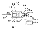
図14は、RFIDトランスポンダー1136及び1160が接点1166aと1166b及び1168aと1168bで形成される双方向性接点クロージャポートを有する、別の実施形態の、コネクタ1120とハウジング1134の別の組合せを示す。したがって、RFID集積回路チップ1138及び1162はそれぞれの識別情報を他方の、情報が読み取られてセーブされる、集積回路チップに出力するように指示することができ、一方または両方からそのような情報を検索するためにポーリングを行うことができるであろう。いくつかの実施形態において、RFIDトランスポンダーはNビット転送技術を用いて1つ以上の他のRFIDトランスポンダーの識別情報を転送し、1つの集積回路が規則的間隔で接点クロージャを強制的にN回動作(開または閉)させて、強制された接点クロージャを検知する他の(1つまたは複数の)集積回路に(識別情報のような)データビットを提供する。また別の実施形態は、他の電気技術及び/または熱技術または光技術を用いて、RFIDトランスポンダー間で情報を転送する。このRFIDトランスポンダーの相互識別手法により、整合するコネクタとアダプタの情報を得るための自動識別が可能になるであろう。RFID集積回路チップ1138及び1162には追加の電力及び追加の双方向通信と検知の機能が必要になり得るであろう。この場合も、この手法により、プラグの抜き差しまたはボタン等の操作を行わずにコネクタパネル全体の目録作成が可能になる。
FIG. 14 shows another embodiment of a
図15は、RFID機能を用いる光ファイバケーブルコネクタのマッピングを可能にするための、上に開示したコネクタのいくつかの特徴を組み込んでいるシステムの一代表例を示す。様々な実施形態がRFIDトランスポンダーに付帯するコンポーネントの物理的な場所のマッピング及び/またはそのRFIDトランスポンダーに付帯するコンポーネントの接続性のマッピングを提供する。図15を改めて参照すれば、簡略に示されているように、システム1200は、ハウジング1202,リーダー1204及び光ファイバケーブル1206を備える。光ファイバケーブル1206のそれぞれはコネクタ1208(1),1208(2)を有する。その他のコネクタ例1208(3)〜1208(18)については以下でさらに説明する。説明を簡単にするため、ハウジング1202は1つのコネクタ1208(1)を受け入れる1つのアダプタ1210(1)を有するように示される。しかし、ハウジング1202は複数のコネクタを受け入れるための複数のそのようなアダプタを有することができる。ハウジング1202は、ルーター、サーバー、いずれかの接続されたデバイス、無線デバイス、パッチパネル、アダプタ、さらに別のコネクタ、等のような、光ファイバケーブルネットワークの内のいかなる要素も有することができる。したがって、光ファイバケーブルを取り付けることができるいかなるデバイスもハウジング1202を含み得るであろう。
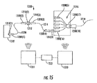
FIG. 15 shows one representative example of a system that incorporates some of the features of the connector disclosed above to enable mapping of fiber optic cable connectors using RFID functionality. Various embodiments provide a mapping of the physical location of components attached to an RFID transponder and / or a mapping of the connectivity of components attached to that RFID transponder. Referring again to FIG. 15, the
それぞれのコネクタ1208は(図15には見ることができない)付帯RFIDトランスポンダーを有する。RFIDトランスポンダーは上に論じたタイプの内の1つとすることができる。したがって、RFIDトランスポンダーは完全にまたは一部がコネクタに配される。また、状態及び/または状態の変化を検出し、これをRFIDトランスポンダーに通信するための状態応答素子も有することもできる。状態応答素子は、コネクタプラグのアダプタへの差込みを検知するための、電気接点、プッシュボタン操作素子、接点クロージャ構造またはその他の構造を有することができる。アダプタは、状態応答素子から信号を受け取り、検出された状態に関する信号を送るための、RFIDトランスポンダーを有することもできる。したがって、コネクタ1208がアダプタ1210に受け入れられると、状態の変化が上述した構造または機能の1つ以上によって記録される。そのような差込みの前後のRFIDトランスポンダーの、あるいは接点クロージャ命令の送信及び再ポーリングによる、ポーリングはどのコネクタ及び/またはアダプタが接続されているかを識別するであろう。差し込まれたコネクタ、この場合は1208(1)内の情報は、光ファイバケーブル1206の他端にコネクタ1208(2)がある、またはあるはずである、ことも識別するであろう。この情報は、例えば、コネクタ1208(2)を特定のアダプタに接続するため、ケーブルにコネクタを付けるため、等に利用され得る。
Each
このマッピング機能は拡張することができる。例えば、コネクタ1208(2)はさらに、パッチパネルまたはアダプタとすることができる、別のハウジング1212のアダプタ1210(2)によって受け入れられ得る。この場合も、状態応答素子が差込みを検出することができ、この検出は様々な態様でリーダー1204に報告され得る。ハウジング1212は別のコネクタ1208(3)を受け入れるための別のアダプタ1210(3)を有することができ、プロセスはさらに継続し、コネクタ1208(3)の差込みは光ファイバケーブル1214の他端にあるコネクタ1208(4)の識別を生じさせることができる。
This mapping function can be extended. For example, the connector 1208 (2) may further be received by an adapter 1210 (2) in another
情報は、所望に応じて、様々な態様でフレキシブルに管理され得る。例えば、アダプタ1210(2)及び1210(3)は、望ましければ、2つのコネクタ1208(2)及び1208(3)を接続する単一のアダプタと見なすことができる。また、内部配線(図示せず)によってアダプタ1210(2)及び1210(3)を、例えばパッチパネルハウジングの内部で、接続することができるであろう。内部配線は、例えば、コネクタ1208(2)と1208(3)を直接にまたは、上述したように、状態の変化を検出するかまたは通信するための構造を有するアダプタを介して、接続することによりRFID機能を有することができるであろう。あるいは、それぞれのアダプタの一意的な識別情報を相関させることによってどのアダプタがパッチパネル内で内部接続されているかに関する情報をデータベースが保持することができ、コネクタ及びアダプタだけでRFID機能を用いることができるであろう。 Information can be flexibly managed in various ways as desired. For example, adapters 1210 (2) and 1210 (3) can be considered as a single adapter connecting two connectors 1208 (2) and 1208 (3) if desired. Also, adapters 1210 (2) and 1210 (3) could be connected by internal wiring (not shown), for example within the patch panel housing. Internal wiring can be achieved, for example, by connecting connectors 1208 (2) and 1208 (3) directly or via an adapter having a structure for detecting or communicating a change in state as described above. It would be possible to have an RFID function. Alternatively, the database can maintain information about which adapters are internally connected in the patch panel by correlating the unique identification information of each adapter, and the RFID function can be used only by connectors and adapters. It will be possible.
タイプ及びそれぞれの末端にあるコネクタの数が異なるケーブルも同様にRFID機能を用いることができる。図示されるように、光ファイバケーブル1216は分離された12本の個々の光ファイバを有する。この分離構造は光ファイバファンアウトアセンブリと称することもできる。コネクタ1208(5)〜1208(16)(図示せず)はそれぞれファイバの内の1本を終端するが、コネクタ1208(17)は多芯コネクタである。コネクタ1208(4)はコネクタ1208(16)に、直接にまたは、アダプタ1210(4)のような、アダプタを介して、接続される。光ファイバケーブル1218は、多芯コネクタ1208(18)を有する、別の12ファイバケーブルである。コネクタ及びアダプタのそれぞれは、差込みのような状態を検出するための状態応答素子が付帯する、上述したようなRFIDトランスポンダーを有することができる。また、ケーブルのそれぞれのコネクタのRFIDトランスポンダーには、製造工場及び/または現場において、そのケーブルに取り付けられた他の1つまたは複数のコネクタに関する情報を与えることもできる。さらにまたはあるいは、RFIDトランスポンダーは、例えば図14の実施形態に関して上述したNビット転送を用いる、RFIDリーダーとの以降の通信のため、相互に通信して相互を識別し、他のRFIDトランスポンダーの識別情報を(好ましくは集積回路チップ内の)メモリに格納することが可能であり得る。したがって、ケーブルの一端におけるプラグ差込みによりRFIDトランスポンダーを介してケーブル及び/またはファイバの他端に関するいくらかの情報を得られる。任意の数のファイバをケーブル内に用いることができ、多芯ケーブルからの任意の数の分離を用いることができることは当然である。また、両端のそれぞれに多芯コネクタをもつ多芯ケーブルを用いることもできるであろう。
RFID functions can also be used with cables of different types and number of connectors at each end. As shown, the
本開示の目的のため、(パッチパネルアダプタ自体、等にではなく)他のコネクタまたは他のコネクタに直接に接続されているコネクタはコネクタが接続されるアダプタまたはハウジングと見なされ得ることを心にとめておくべきである。したがって、本明細書に説明される利点は、2つのコネクタが、アダプタの有無にかかわらず、接続し合わされたときを認識することができ、よってこの状況においては一方のコネクタまたはアダプタが他方のコネクタに対する「アダプタ」と見なされることである。したがって、いくつかの状況において、コネクタが接続する要素は、本開示の目的のため、「アダプタ」と見なされるであろう。 For the purposes of this disclosure, keep in mind that other connectors or connectors that are directly connected to other connectors (not the patch panel adapter itself, etc.) can be considered the adapter or housing to which the connector is connected. It should be stopped. Thus, the advantages described herein can recognize when two connectors are connected together, with or without an adapter, so in this situation one connector or adapter is the other connector. Is to be considered an "adapter" to Thus, in some situations, the element to which the connector connects will be considered an “adapter” for purposes of this disclosure.
多芯ケーブル用RFIDトランスポンダーは、ファイバの順序及び極性のような、追加情報を保持することができる。多芯コネクタが多芯ファイバ内のファイバの順序付けに関する情報を有していれば、システム全体にわたる通信路をより高い確度をもってマッピングすることにより、機能を向上させることができる。そのようなマッピングは様々なコンポーネントに関する、物理的場所、接続性及び/またはその他のパラメータの、マッピングを含むことができる。 RFID transponders for multi-core cables can hold additional information such as fiber order and polarity. If the multicore connector has information regarding the ordering of the fibers in the multicore fiber, the function can be improved by mapping the communication path over the entire system with higher accuracy. Such mapping can include mapping of physical location, connectivity and / or other parameters for various components.
そのようなシステム1200は、望ましければ、第2のリーダー1220を用いることができる。リーダー1220は技工によって用いられる手持ちリーダーとすることができるであろう。さらにまたはあるいは、リーダー1220は、システム1200の有効範囲をリーダー1204だけを用いる場合より広いエリアにわたって拡大できるように、(リーダー1204のような)第2の固定リーダーとすることができるであろう。望ましければ、データベース1222を、無線で及び/または実配線によりリーダー1204及び1220に接続された、汎用または専用のコンピュータに格納することができる。データベース1222は、コネクタ/アダプタ接続、RFID呼掛け及び応答、過去及び現在の状態、状態の変化、等の記録を含む、上に論じたような様々な記録を維持することができる。
Such a
プラグ差込みのような状態の変化の、おそらくは光ファイバケーブル及び/またはファイバ順序付けによって登録されたコネクタ識別に関する情報と組み合わせた、使用により、ネットワークの設置、保守及び変更のための様々なレベルの詳細及び機能を得ることができる。したがって、上の教示を用いて、差込み及び/またはボタン押し、あるいはその他の状態応答素子作動時に基本的にそれ自体を自動マッピングするネットワークをつくりだすことが可能である。また、そのようなシステムはコネクタ及びアダプタのRFIDトランスポンダーの近接性だけには依存せず、望ましければそのような機能はそのようなシステムの一部内で利用することもできるであろう。 The use of state changes such as plug plugging, possibly combined with information regarding connector identification registered by fiber optic cable and / or fiber ordering, provides various levels of detail for network installation, maintenance and modification and Function can be obtained. Thus, using the above teachings, it is possible to create a network that essentially auto-maps itself upon insertion and / or button press or other state response element activation. Also, such systems do not rely solely on the proximity of the connector and adapter RFID transponders, and such functionality could be utilized within a portion of such systems if desired.
状態応答素子を有する、本明細書に開示される実施形態を再び参照すれば、また別の実施形態は、1つ以上のコンポーネント(及び/またはそれぞれのコンポーネントのプラグまたはソケット)に付帯し、状態応答素子によって検知される状態を発生するように適合された、状態発生素子を含む。実施形態例は図9〜14に示されるシステムを含み、コネクタRFIDトランスポンダー及びアダプタRFIDトランスポンダーの一方が状態応答素子を有し、他方のRFIDトランスポンダーが状態発生素子を有する。様々な実施形態の状態発生素子は、何らかの事態が生じたとき、例えば、プラグがソケットに差し込まれたとき、状態発生素子を有するRFIDトランスポンダーが状態の発生を命令するようにとの通信をRFIDリーダーから受けたとき及び/または、状態応答素子が状態を検出できるような、同様の状態が生じたときに、状態を発生する。状態発生素子によって発生される状態はいかなる形態もとることができ、非限定的例には、電気的接続を介する電流、あらかじめ定められたRF信号、可視表示、可聴表示、または同様の状態がある。いくつかの実施形態において、発生された状態を状態応答素子が検出するためにはプラグが少なくともある程度ソケットに受け入れられなければならないが、別の実施形態においては状態応答素子及び状態発生素子が付帯する2つのコンポーネントが物理的に接触している及び/またはある相互距離内にある必要はない。図14の実施形態の状態発生素子は他のRFIDトランスポンダーの状態応答素子(集積回路の一部)によって検出される接点クロージャを強制して、状態発生素子をもつRFIDトランスポンダーからのNビット転送による情報の、状態応答素子をもつRFIDトランスポンダーによる受け取りを可能にする。状態発生素子と状態応答素子の使用により、2つのRFIDトランスポンダーの、2つのコンポーネントを相関させるため、相互に関する識別情報を転送及び/または格納するため、及び/または技工が望む他の機能を実施するための、2つのRFIDトランスポンダーの相互通信が可能になる。 Referring again to the embodiments disclosed herein having a state response element, another embodiment attaches to one or more components (and / or plugs or sockets of each component) and states Including a state generating element adapted to generate a condition sensed by the response element. An example embodiment includes the system shown in FIGS. 9-14, where one of the connector RFID transponder and the adapter RFID transponder has a state response element and the other RFID transponder has a state generation element. The state generating element of various embodiments can communicate with an RFID reader when an event occurs, for example, when a plug is inserted into a socket, an RFID transponder having the state generating element commands the generation of the state. A state is generated when a similar state occurs such as when received from and / or the state response element can detect the state. The state generated by the state generating element can take any form, and non-limiting examples include current through electrical connections, predetermined RF signals, visual display, audible display, or similar state . In some embodiments, the plug must be received in the socket at least to some extent in order for the status response element to detect the generated condition, but in other embodiments, the status response element and the status generation element are incidental. The two components need not be in physical contact and / or within a certain distance. The state generation element of the embodiment of FIG. 14 forces contact closure detected by the state response element (part of the integrated circuit) of another RFID transponder, and information by N-bit transfer from the RFID transponder with the state generation element. Reception by an RFID transponder having a state response element. Use of state generators and state responsive elements to correlate the two components of the two RFID transponders, transfer and / or store identification information about each other, and / or perform other functions desired by the technician Thus, the two RFID transponders can communicate with each other.
図15を参照して上に説明したように、例えば、2つ以上のコネクタを有し、それぞれのコネクタが付帯RFIDトランスポンダーを有している、光ファイバドロップケーブルのような、コンポーネントの様々な部分に付帯する2つ以上のRFIDトランスポンダーを1つのコンポーネントが有することができる。いくつかの実施形態において、コンポーネントに付帯するRFIDトランスポンダーのそれぞれは他のRFIDトランスポンダー及び/またはRFIDトランスポンダーが付帯するコンポーネントの部分の識別情報を含む。そのような実施形態において、RFIDトランスポンダーの1つとの通信は、RFIDシステムの性能を向上させるため、1つより多くのRFIDトランスポンダーに関する、識別情報等のような、情報のRFIDリーダーによる受け取りを可能にすることができる。別の実施形態において、別のコンポーネント(または同じコンポーネント)のRFIDトランスポンダーは、ただ1つのRFIDトランスポンダーとの通信によるRFIDリーダーへのRFIDトランスポンダーのそれぞれの情報の通信を可能にするため、相互に通信するように適合される。これらの別の実施形態のいくつかにおいて、RFIDトランスポンダーの集積回路チップは、他のRFIDトランスポンダーの識別情報をその中に格納することができ、そのような別の識別情報をRFIDリーダー及び/または他のRFIDトランスポンダーに提供するためにそこから検索することができる、メモリを有する。いくつかの実施形態のメモリは、情報を永続的に保持することができ、あらかじめ定められた時間間隔で情報を消去することができ、命令されたときに情報を消去することができ、及び/または、1つの非限定的例を挙げれば、プラグがソケットから抜かれるような、特定の事態が生じたときに情報を消去することができる。 As described above with reference to FIG. 15, various parts of a component, such as a fiber optic drop cable, for example, having two or more connectors, each connector having an associated RFID transponder A component can have more than one RFID transponder incidental to the. In some embodiments, each of the RFID transponders associated with the component includes identification information of other RFID transponders and / or the portion of the component that the RFID transponder is associated with. In such an embodiment, communication with one of the RFID transponders allows the RFID reader to receive information, such as identification information, for more than one RFID transponder to improve the performance of the RFID system. can do. In another embodiment, RFID transponders of different components (or the same component) communicate with each other to allow communication of the respective information of the RFID transponder to the RFID reader by communication with only one RFID transponder. To be adapted. In some of these alternative embodiments, the RFID transponder integrated circuit chip may store identification information of other RFID transponders therein, such alternative identification information may be stored in an RFID reader and / or other Having a memory from which it can be retrieved for provision to an RFID transponder. The memory of some embodiments can retain information permanently, can erase information at predetermined time intervals, can erase information when instructed, and / or Or, in one non-limiting example, the information can be erased when a specific event occurs, such as the plug being removed from the socket.
上記の観点において、上記実施形態またはそれらのコンポーネントの多くの改変及び再構成がなされ得ることは明らかである。コネクタ、アダプタ、コネクタ付ケーブル、コネクタ及びアダプタを含む接続、及びマッピングシステムは、上記の特徴及び機能のいくつかまたは多くを有することができる。1つ以上の状態応答素子が状態の差を検出することができる。RFIDトランスポンダーによるかまたはRFIDトランスポンダー間の、検出された状態の通信は、単一パネル上の、またはネットワークにわたる、全ての接続のマッピングを含む、1つ以上のコネクタ、ケーブルまたは接続の識別またはマッピングのための有用な情報を提供することができる。一種または別種の検出された状態が情報を提供するから、相対的近接RFID機能を必要とする別のシステムに頼る必要はない。アダプタへのコネクタの差込みによっておこされる状態の変化は、得られる情報を近接度依存システムより正確にし、よって第一種過誤を減じるかまたは排除する、コネクタ公差をもって設計することもできる。さらに、そのような状態変化利用システムは、パネルがより多くの接続をより密な間隔で効率的に有することを可能にする。また、様々な機能及び目的のための後のRFID通信のために過去及び現在の状態情報を格納することができる。望ましければ、所望の用途、追加のコネクタの必要、電力、等に依存して、RFIDトランスポンダーハードウエアの、いくつか、ほとんど、または実質的に全てをコネクタまたはハウジングに配置することができる。
In view of the above, it will be apparent that many modifications and reconfigurations of the above embodiments or their components may be made. Connectors, adapters, cables with connectors, connections including connectors and adapters, and mapping systems can have some or many of the features and functions described above. One or more state responsive elements can detect a difference in states. Detected state communication by or between RFID transponders includes the identification or mapping of one or more connectors, cables or connections, including mapping of all connections on a single panel or across a network. Can provide useful information for. Since one or another type of detected condition provides information, there is no need to rely on another system that requires relative proximity RFID functionality. The change in state caused by the insertion of the connector into the adapter can also be designed with connector tolerances that make the resulting information more accurate than proximity-dependent systems, thus reducing or eliminating
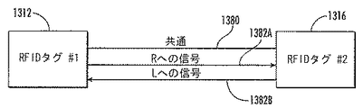
上述した環境におけるように、複数のRFIDタグが接続され得る場合、RFIDタグは相互にまたは1つ以上の他のデバイスと直接に通信できることが望ましいであろう。詳細な説明及び添付図面において以下で詳細に述べられるように、開示されるプロトコル並びに関連するシステム及び方法を用いることにより、2つ以上のRFIDタグ間の多大な通信でRFIDリーダーに負担をかける必要なしにRFIDタグ−タグ間接続性を判定することができる。2つ以上のRFIDタグの接続性が確立されてしまえば、2つ以上の結合RFIDタグはRFIDタグ間の直接接続を用いて相互の通信を続けることができる。このようにして、2つ以上の結合RFIDタグは結合RFIDタグ間で、信号、データまたはその他の情報を送ることができる。 Where multiple RFID tags can be connected, as in the environment described above, it may be desirable for the RFID tags to be able to communicate directly with each other or with one or more other devices. As described in detail below in the detailed description and accompanying drawings, it is necessary to strain the RFID reader with significant communication between two or more RFID tags by using the disclosed protocol and related systems and methods. Without RFID tag-tag connectivity can be determined. Once the connectivity of two or more RFID tags is established, the two or more combined RFID tags can continue to communicate with each other using a direct connection between the RFID tags. In this way, two or more combined RFID tags can send signals, data or other information between the combined RFID tags.
図16は、複数のRFIDタグが相互に通信することが望ましい、複数のRFIDタグを接続することができる環境の一例の略図である。図16は、第1のコネクタ1314のRFIDタグ1312が第2のコネクタ1318のRFIDタグ1316と電気的に通信している、これら2つの間の識別情報を含む、可能な情報交換をさらに説明するための、コンポーネント結合システム1310の実施形態例を示す。図16はRFIDタグ1312及びRFIDタグ1316に関して論じられるが、RFIDタグ1312及び1316は1つのデバイスに配置され得るであろうことに注意されたい。さらに、RFIDタグ1312及び1316の代わりにRFIDタグをエミュレートするデバイスを用いることができるであろう。一実施形態において、RFIDタグ1312及びRFIDタグ1316の代わりにデバイス1312及びデバイス1316を用いることができ、2つのデバイスは、以下でさらに詳細に説明されるように、RFIDタグ1312とRFIDタグ1316が相互に通信する態様と同様の態様で相互に通信することができる。
FIG. 16 is a schematic diagram of an example environment in which a plurality of RFID tags can be connected where it is desirable for the plurality of RFID tags to communicate with each other. FIG. 16 further illustrates possible information exchange, including identification information between the two, wherein the
RFIDタグ1312及び/またはRFIDタグ1316は第1のコネクタ1314の第2のコネクタ1318への結合及び/または第1のコネクタ1314のからの分切離しを可能にするように構成することができる。第1のコネクタ1314は第2のコネクタ1318の本体1317に結合されるように適合された本体1315を有することができる。この例における第2のコネクタ1318は、第1のコネクタ1314の本体1315の相補的な嵌合形状寸法を受け入れるようにつくられた形状寸法を有する、第2のコネクタ1318の本体1317に配された内部チャンバ1319を有する。結合または分離は、必要ではないが、第1のコネクタ1314によって第2のコネクタに、またはその逆に、提供される識別情報に基づくか、あるいは第1のコネクタ1314と第2のコネクタ1318の両者間の識別情報交換に基づくことができる。結合及び切離しは、第1のコネクタ1314によって第2のコネクタに、またはその逆に、提供される識別情報の受取りには基づかないこともできる。RFIDタグ1312.1316は、コネクタ1314,1318が結合されるかまたは切り離されるべきであるか否かを判定するための処理を実施することができ、あるいは、そのような処理はRFIDリーダーシステム1320または他のシステムによって実施することができる。RFIDリーダーシステム1320または他のシステムは、例として識別情報を受け取るため、RFIDタグ1312,1316の1つ以上と無線通信することが可能であり得る。コネクタ1314,1318の結合または切離しは、識別情報が定められた規準または所望の接続構成にしたがって適切であると見なされるか否かに基づくことができる。
この点に関し、図16の例に示されるように、第1のコネクタ1314は第2のコネクタ1318に結合される。第1及び第2のコネクタ1314,1318の集積回路(IC)チップ1322,1324はそれぞれ、ICチップ1322,1324に関する識別情報を格納している、メモリ1326,1328を有する。したがって、この識別情報は第1のICチップ1322を第2のICチップ1324から明確に、したがって第1のコネクタ1324を第2のコネクタ1318から明確に、識別するために用いることができる。識別情報は、RFIDリーダーシステム1320の一部として備えられるRFIDリーダー1330に通信することができる。
In this regard, the
一実施形態において、RFIDタグ1312,1316は受動型デバイスである。受動型RFIDデバイスはそれぞれ自体の電源を必要としない。この実施形態においてRFIDタグ1312,1316が受動型タグである場合、ICチップ1322,1324は、ICチップ1322,1324に結合されたアンテナ1334,1336を介してRFIDリーダー1330から取り入れられるかまたは受け取られるRFエネルギーから電力を供給され得る。電力は、RFIDリーダーシステム1320のRFIDリーダー1330によって送信され、アンテナ1334,1336によって受け取られる、呼掛け信号1332から取り入れることができる。したがって、電源の装備が望ましくないか、そうではなくともコストまたは寸法の制限により実用的ではない場合には、受動型RFIDデバイスが望ましいであろう。アンテナ1334,1336は、所望の受信及び/または送信周波数に同調された、ダイポールアンテナ及びモノポールアンテナを含むがこれらには限定されない、いずれかのタイプのアンテナとすることができる。アンテナ1334,1336は外部アンテナとするかまたはICチップ1322,1324に組み込むことができる。
In one embodiment,
ICチップ1322,1324はRFIDタグ1312,1316に対していくつかの機能及び通信を可能にする。この点に関し、アンテナ1334,1336がRFIDリーダーからRF信号を受け取っていないときにICチップ1322,1324に電力を供給するため、及び/または所要電力がアンテナ1334,1336を介して取り入れられる電力より大きくなり得る時間中にそのような電力を補助するため、アンテナ1334,1336を介して受け取られる剰余エネルギーを蓄えるためにキャパシタ1335,1337を電気が通じる態様でICチップ1322,1324に結合させることができる。RFIDタグ1312,1316は半受動型デバイスまたは能動型デバイスとすることもできるであろうことに注意されたい。半受動型RFIDタグはRFIDタグへの電力供給を補助するための電源を有することができる。能動型RFIDタグは電源及び送信器を有する。
この実施形態においても、第1のコネクタ1314及び第2のコネクタ1318はいずれも、それぞれがそれぞれのICチップ1322,1324に結合された、1本以上の電気リード線1342,1344を含むインターフェース1338及び1340のそれぞれを提供する。電気リード線1342,1344はこの実施形態において、図16に示されるように、第1のコネクタ1314が第2のコネクタ1318に結合されたときに結線接続を形成するため、相互に直接に接触するように設計される。電気リード線1342,1344がこの実施形態において接続の結果として相互に直接に電気的に接触すると、接続イベントがおこる。応答して、第1及び第2のコネクタ1314,1318のICチップ1322,1324がそれぞれ、電気リード線1342,1344を通して相互に通信を開始する。電気リード線1342,1344間の直接オーミック接触以外の、容量結合及び誘導結合を含む、接触も可能である。
Also in this embodiment, both the
第1のコネクタ1314の第2のコネクタ1318への接続を示すため、メモリ1326,1328にそれぞれ格納された第1のコネクタ1314及び第2のコネクタ1318の個体情報に関するに関する識別情報を交換及び格納することができる。同様に、第1のコネクタ1314と第2のコネクタ1318の間の接続がなされていないことを示すため、識別情報の交換の欠如を用いることができる。すなわち、例えば、第1のコネクタ1314のICチップ1322が第2のコネクタ1318のICチップ1324の識別情報を受け取って格納すれば、第1のコネクタ1314のICチップ1322に呼び掛けているRFIDリーダー1330は第1のコネクタ1314が第2のコネクタ1318と結合されていると判定することができる。逆でも同じことが可能である−RFIDリーダー1330が第2のコネクタ1318に呼び掛け、第2のコネクタ1318が第1のコネクタ1314に結合されているか否かを判定するため、ICチップ1324に格納されたICチップ1322の識別情報に関する識別情報を用いることができる。第1のコネクタ1314が第2のコネクタ1318に結合されていないことを第1のコネクタ1314及び/またはRFIDリーダー1330に示すため、第1のコネクタ1314と第2のコネクタ1318の間で交換された識別情報の欠如を用いることができる。以下でさらに十分に論じられる別の実施形態において、RFIDタグ1312,1316のそれぞれはRFIDリーダー1330を用いずに1つ以上の他のRFIDタグとの結合の有無を判定することができる。
To indicate the connection of the
第1のコネクタ1314及び第2のコネクタ1318の一方は、またはいずれも、あるいは第1のRFIDタグ1312及び第2のRFIDタグ1316の一方は、またはいずれも、それぞれの他方のコネクタ1318,1314とも、RFIDリーダー1330とも、それぞれ自体の識別情報を通信することも、識別情報を交換することもできる。第1及び第2のコネクタ1314,1318は、あるいは第1のRFIDタグ1312及び第2のRFIDダグ1316の一方は、またはいずれも、シリアル番号、コネクタのタイプ、ケーブルタイプ、製造業者、製造年月日、装着年月日、場所、ロット番号、(装着中に測定された減衰のような)性能パラメータ、ケーブルの他端に何があるかの識別情報、等のような、メモリに格納されている他の情報を通信することができる。そのような情報は、製造業者において、または設置時にRFIDリーダー1330を介して、RFIDタグ1326,1328のメモリにあらかじめロードすることができるであろう。RFIDリーダー1330に結合されたRFIDリーダーシステム1320は、RFIDリーダー1330の有効範囲の、第2のコネクタ1318に結合された第1のコネクタ1314を示す識別情報対を受け取るように構成することができる。この情報は、図16に示されるように、RFIDリーダーシステム1320に備えられたデータベース1349に、コンポーネント管理システム1348において処理して格納することができる。コンポーネント管理システム1348は、多くの作業を実施するため、第1及び第2のコネクタ1314,1318から受け取った情報を処理するための制御システム及び関連ソフトウエアを備えることができる。これらの作業には、以下でさらに詳細に説明されるように、識別情報対の記録、技工への識別情報対の情報の提供、どのコネクタが結合されていないかの記録並びにその他のトラブルシューティング情報及び診断情報の提供があるが、これらには限定されない。処理には、識別情報に基づいて、RFIDタグ1312,1316にRFIDタグ1312,1316が付帯するコンポーネントの結合または分離を可能にさせる命令を与えるため、RFIDタグ1312,1316の一方に、またはいずれにも、通信するか否かの意思決定を含めることができる。さらに、コンポーネント管理システム1348及びいずれかの付帯データベース及び/または処理要素は、1つ以上のRFIDタグから受け取られた情報の識別、マッピングまたはその他の処理を容易にするため、1つ以上のRFIDタグに関する格納された情報を有する。さらに詳しくは、RFIDリーダー1330は、RFIDタグ1312,1314の一意的な識別番号を、第1及び第2のコネクタ1314,1318にそれぞれ、また、技工が第1及び第2のコネクタ1314,1318を動かそうとする及び/またはモニタするときに知りたいであろう、いずれか他のパラメータ、接続、関連またはその他の情報とも、相関させる情報を有する。
One or both of the
RFIDタグ1312,1316のICチップ1322,1324がどのようにして相互に通信可能な態様で結合され得るかに関するさらなる詳細を例で提供するため、図17が与えられる。図17は、図16のコンポーネント結合システム1310の一例のRFIDタグ1312,1316のICチップ1322,1324のチップ及びピンレイアウトの例をさらに詳細に示す。ICチップ1322,1324は、それぞれの第1のコネクタ1314と第2のコネクタ1318が結合されたときに相互に電気的にまた通信可能な態様で接続される。RFIDタグ1312,1316のICチップ1322,1324は、第1及び第2のコネクタ1314.1318間の接続がなされたときに相互に接続される。
FIG. 17 is provided to provide further details on how the
この実施形態において、それぞれのICチップ1322,1324はRF入力ピン1350,1352の形態のRF入力を有する。ICチップ1322,1324に接続されるアンテナ1334,1336(図16)は、RF入力ピン1350,1352を介してRFIDリーダー1330(図16)からRF通信信号を受け取るように構成される。RF入力ピン1350,1352は、ダイポールアンテナ、モノポールアンテナ、ループアンテナ、または他のいずれかのタイプのアンテナを含む、いずれのタイプのアンテナもサポートできることに注意されたい。RF入力ピン1350,1352に接続されるアンテナは、例として、2.4ギガヘルツ(GHz)及び900メガヘルツ(MHz)を含む、所望のいずれかの周波数で動作するように構成することができる。
In this embodiment, each
図17にさらに示されるように、RFID対応ICチップ1322,1324は、ポイントツウポイント態様で結合されるように設計することができる。接地線1358を介してICチップ1322,1324の接地ピン1354,1356を接続することで接続が確立されたときに、それぞれのICチップ1322,1324に対して接地が接続される。RF通信信号による電力供給がなされていないときのICチップ1322の動作を可能にするためにRF通信信号から受け取った電力のエネルギー貯蔵を提供するため、PWRピンとGNDピンの間に1つ以上のキャパシタ1360を接続することができる。また、図17に示されるように、ICチップ1322,1324はシリアル通信線1362を通じて相互に通信するようにも構成される。それぞれのICチップ1322,1324は少なくとも1つの通信ピン1364,1366を有する。それぞれの通信ピン1364,1366はICチップ1322,1324への/からのシリアル通信を可能にする。図17には示されていない別のRFIDタグの一部としての、別のICチップは、そのICチップに第2の通信ピンが設けられていれば、(以下の図23に示されるように)デイジーチェーン態様で相互に接続し、通信可能な態様で接続することができるであろう。
As further shown in FIG. 17, RFID-enabled
RFIDリーダー1330による呼掛け中に充電されるように、また、RFIDリーダー1330によって呼び掛けられていないときあるいはRFIDリーダー1330からのエネルギーが散発的であるか、そうではなくとも第2のコネクタ1318に電力を供給するに十分に強くはないときに、予備電力を供給するために、キャパシタバンク1378をRFIDタグ1316に備えることもできる。
The
図16及び17は説明のための環境に過ぎず、RFIDタグを相互に接続または結合することができる、他の環境または設定があり得ることに注意されたい。例えば、RFID装着電力コネクタが誤って取り外されると、ホストコンピュータシステムは取外しを検出することができるが、電力が中断される前ではない。電力コネクタにより、例えば医療装置のような、クリティカルデバイスへの電力供給が可能になっていれば、電力の中断は生命を脅かし得るであろう。別の例は、接続がなされていること及び適切になされていることを知ることが肝要である、ガス/液体送配システムにおけるカップリングであろう。このことは、誤った接続が重篤な傷害または死をもたらし得る医療用途、様々なプロセスガスまたは高油圧の接続を用いる工業用途、及び結合されるように設計された2つの部品が、適切な接続が存在することを保証するため及び/またはそのような接続が壊れたときに表示または警報を出すために追跡される必要がある、その他の多くの用途において真である。本明細書に開示されるタグ通信は、上記の例を、また、工業制御、衣服、民生エレクトロニクス、機械類、センサシステム、電気的相互接続、流体カップリング、飲料計量供給、セキュリティ認証、及び施錠可能なコンテナに関わる環境も、含むがこれらには限定されない、環境において用いることもできる。実際、本明細書に開示されるタグ通信は2つの結合される部品がそれらの接続または切離しを管理するために識別される必要がある場所であればどこにでも適用することができる。 It should be noted that FIGS. 16 and 17 are merely illustrative environments and that there may be other environments or settings in which RFID tags can be connected or coupled together. For example, if an RFID attached power connector is accidentally removed, the host computer system can detect the removal, but not before power is interrupted. If the power connector allows power to be supplied to a critical device, such as a medical device, interruption of power could be life threatening. Another example would be coupling in a gas / liquid delivery system where it is important to know that the connection is made and that it is done properly. This is because medical applications where incorrect connections can result in serious injury or death, industrial applications using various process gas or high hydraulic connections, and two parts designed to be combined are suitable. This is true in many other applications that need to be tracked to ensure that a connection exists and / or to display or alert when such a connection breaks. The tag communication disclosed herein includes the above examples and also industrial controls, clothing, consumer electronics, machinery, sensor systems, electrical interconnections, fluid couplings, beverage metering, security certifications, and locking Environments involving possible containers can also be used in environments including, but not limited to. In fact, the tag communication disclosed herein can be applied wherever two coupled parts need to be identified to manage their connection or disconnection.
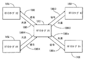
さらに、いくつかの実施形態において、複数のRFIDタグを、(オーミック接触、誘導結合及び容量結合を含むがこれらには限定されない)様々な手段及び(ポイントツウポイント接続、バス接続、リング接続及びスター接続を含むがこれらには限定されない)様々な構成によって、相互に接続することができる。図18及び22〜26はそのような構成の代表的サンプルを示す。これらの図は接続手段及びトポロジーの可能な接続手段、トポロジーまたは組合せの全てを示してはおらず、単に代表的サンプルを示している。 Further, in some embodiments, a plurality of RFID tags can be connected to various means (including but not limited to ohmic contact, inductive coupling and capacitive coupling) and (point-to-point connection, bus connection, ring connection and star connection). They can be connected to each other by various configurations (including but not limited to connections). 18 and 22-26 show representative samples of such a configuration. These figures do not show all possible connection means, topologies or combinations of connection means and topologies, but merely representative samples.
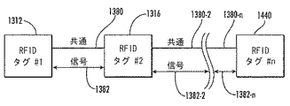
図18はポイントツウポイント接続例の2つのRFIDタグ1312,1316を示す。図18はRFIDタグ1312及びRFIDタグ1316に関して論じられるが、RFIDタグ1312及び1316は同じデバイスに配置され得るであろうことに注意されたい。さらに、RFIDタグをエミュレートするデバイスを、RFIDタグ1312及び1316の代わりに用いることができるであろう。一実施形態において、デバイス1312及びデバイス1316をRFIDタグ1312及びRFIDタグ1316の代わりに用いることができ、2つのデバイスは、以下でさらに詳細に説明されるように、RFIDタグ1312とRFIDタグ1316が相互に通信する態様と同様の態様で、相互に通信することができる。
FIG. 18 shows two
2つのRFIDタグ1312,1316は共通線路1380によって接続される。2つのRFIDタグ1312,1316は(オーミック接触、誘導結合及び容量結合を含むがこれらには限定されない)様々な手段によって相互に接続することができる。図18の実施形態においては、共有双方向性信号線路1382も2つのRFIDタグ1312,1316を接続している。別の実施形態においては、図22に見られるように、それぞれが一方向性である、2本の信号線路が用いられる。共有双方向性線路はハードウエア(ポート、回路配線、等)の経済性を提供できるが、より精緻なエレクトロニクス及びプロトコルが必要になり得る。2本の一方向性信号線路を有する別の実施形態はより単純なエレクトロニクスを用い得るが、より費用がかかる相互接続ハードウエアを用いることになり得る。本明細書に開示される接続されたRFIDタグの様々な構成のそれぞれは共有双方向性信号線とまたは2本以上の一方向性信号線路を用いることができる。
The two
図18のRFIDタグ1312,1316のような1つ以上のタグの間の接続性を判定するためには、何らかの情報がRFIDタグ1312,1316の間で転送される必要がある。一般に、タグ間で共有される物理的信号の実際の性質は重要ではなく、様々な手法によって機能することができるであろう。(図16のRFIDリーダー1330のような)RFIDリーダー及び(RFIDタグ1312,1316)のような一組のタグにより、最も単純化されたタグツウタグ通信機構、すなわち、リーダーからのコマンドを受けたときに1つのタグによりアサートまたはデアサートされ、結合されるタグが連結されたときに結合されたタグによって検知される、連続信号、を用いてさえも接続性を判定することが可能である。以下は、接続性が既知の手順にしたがってどのように判定されるかの例である。
In order to determine connectivity between one or more tags, such as
(図16のRFIDリーダー1330のような)RFIDリーダーがいずれかの新しい接続を探して(RFIDタグ1312,1316のような)一組のタグにクエリーがなされる。結合されたRFIDタグのいかなるあり得るセットにはRFIDタグ1312,1316だけでなく、さらにRFIDタグが存在し得ることに注意されたい。RFIDタグ1312または1316の一方が新しい接続によって識別されると、RFIDリーダー1330はその「接続性信号」のアサートをRFIDタグ1312,1316に求めることができる。RFIDリーダー1330は次いで、今ではその結合RFIDタグからの「接続性信号」を検知することができる1つのRFIDタグを探してRFIDタグのセットの全体にクエリーを実施することができる。結合されたRFIDタグが応答してしまえば、接続されたばかりの2つのRFIDタグがRFIDリーダー1330にわかる。この問い合わせを完了するためには、RFIDリーダー1330は、RFIDリーダー1330が実施しなければならないであろう次のセットのクエリーのための準備として原RFIDタグがその接続性信号をデアサートするようにコマンドを発しなければならないことに注意されたい。この以前の例においてRFIDリーダー1330が接続性を判定するためには、かなりの数の一意的クエリーがなされなければならず、これらのクエリーのそれぞれは多くの電子製品コード第2世代(EPC Gen2)コマンド及びRFIDリーダー1330とRFIDタグセットの間の応答を含み得ることにも注意されたい。RFIDリーダーがRFIDタグ間の接続性を判定するにかかる時間を短縮するためには、本明細書に開示される実施形態及びプロトコルのような、さらに最適な手法を考察することがさらに一層効率的である。
An RFID reader (such as
本明細書に開示される直接タグツウタグ通信の実施形態は、連続信号をアサートするしかない実施形態に対比して、多ビット情報を転送できる能力を可能にする。これにより、RFIDタグ1312,1319(または他の接続されている可能性があるRFIDタグ)のそれぞれに付帯する一意的識別情報の2つのRFIDタグ1312,1316の間の転送が可能になる。これらのタグ識別情報は接続がなされた直後に転送され得るから、付帯する結合されたRFIDタグの識別情報は、新しい接続がなされたことをRFIDリーダー1330が検出したときには既に格納されて、RFIDリーダー1330による読出しが可能になっているであろう。したがって、RFIDリーダー1330は単に、新しい接続を有すると識別された原RFIDタグからの結合されたタグの識別情報の直接読出を行うことができるであろう。今では、(RFIDタグ1312,1316のような)一対のRFIDタグの接続性情報をただ1つの接続されたRFIDタグを識別して読み出すことによって判定することができる。これはRFIDリーダー1330とRFIDタグセットの間に必要な通信量を大きく低減し、結合されたタグの一方にRFIDリーダーがアクセスできない場合に、冗長性を提供する。
The direct tag-to-tag communication embodiments disclosed herein allow for the ability to transfer multi-bit information compared to embodiments that only have to assert a continuous signal. This allows for transfer between the two
本明細書に開示される直接タグツウタグ通信実施形態に対しては、RFIDタグ1312,1316がタグ識別情報の転送を開始するために、あるタイプのプロトコル開始方法が必要である。一実施形態において、RFIDタグ1312,1316のそれぞれはコマンドプロトコルを用いて識別情報を直接交換するように構成される。すなわち、RFIDタグ1312,1316はいずれも、RFIDタグ1312,1316の間の接続性を判定するために同じプロトコルを用い、接続されたRFIDタグ1312,1316の間で通信するために同じプロトコルを用いるであろう。
For the direct tag-to-tag communication embodiment disclosed herein, some type of protocol initiation method is required for
図19は、一実施形態例にしたがう、複数の接続されたRFIDタグ間の接続性判定及び通信のための全体プロトコルの例を示す、一般化されたフローチャートである。プロトコルはブロック1384に始まる。信号はRFIDタグ1312,1316の一方によってアサートまたはデアサートされ得る。一実施形態において、この信号はRFIDリーダー1330からのコマンドを受けるとアサートまたはデアサートされ得る。ブロック1386において、RFIDタグ1312,1316の一方によって信号が検知されると、接続されたタグがデータ転送を開始していると判定される。ブロック1386のこのステップは、通信プロトコルの開始に先立ち、RFIDタグ1312,1316によって電気的に行われ得る。RFIDタグ1312,1316間の接続が検出されると、次いでRFIDタグ1312,1316はタグ識別情報を交換することができる(ブロック1388)。接続されたRFIDタグ1312,1316の情報はそれらが適するいかなる目的にも用いられ得る(ブロック1390)。RFIDタグの情報はいつでもRFIDリーダーがアクセスでき、いつでも用いることができる。接続されたタグの識別情報が交換されてしまうと、タグ識別情報は適するいずれの目的にも用いられ得る。これには、接続イベントまたは結合されたタグの個体情報のRFIDリーダーへの通信のような、ただしこれには限定されない、いずれかの目的のための接続されたタグの個体情報の使用が含まれるであろう。別の非限定的実施形態において、結合RFIDタグ1312,1316は、RFIDシステムに存在する通信コンポーネントを自動的に見いだすため並びに2つの特定の通信コンポーネントが接続または結合されたとき及びその接続が切り離されたときを判定するため、例としてコネクタ及びアダプタのような、通信コンポーネントに関する情報を提供するために用いることができる。この情報は、タグ情報の交換の前後で、いつでも提供され、使用され得る。どこかの時点で結合RFIDタグ1312,1316の一方の切離しが検出され得る(ブロック1392)。この時点において、方法は開始ステップに戻り、別の結合されたRFIDタグの検出に向かう。一実施形態において、結合されたタグの個体情報はクリアされ、クリアされたという情報はRFIDリーダーが、RFIDタグがもはや接続されていることを判定するため、またはRFIDタグのステータスを判定するために用いられ得る。この点に関し、語「切離し」はRFIDタグまたはその他のデバイスを切り離す行為を含み得るが、これには限定されない。接続されていないRFIDタグは切離し状態にあるということができる。
FIG. 19 is a generalized flowchart illustrating an example of an overall protocol for connectivity determination and communication between a plurality of connected RFID tags according to an example embodiment. The protocol begins at
図20は、一実施形態例にしたがう、複数の接続されたRFIDタグ間のタグ識別情報の交換を含む、図19のプロトコルをさらに詳細に示すフローチャート例である。図20において、プロトコルはブロック1394に始まる。信号はRFIDタグ1312,1316の一方によってアサートまたはデアサートされ得る。一実施形態において、この信号はRFIDリーダー1330からのコマンドを受けるとアサートまたはデアサートされ得る。ブロック1396において、RFIDタグ1312,1316の一方によって信号が検知されたときに、接続されたタグが検出される。次いで、RFIDタグ1312,1316間の通信チャネルが使用できることを確証するためのステップがブロック1398においてとられる。通信チャネルが使用できることを保証するために、標準的な競合解消方法を適用することができる。
FIG. 20 is an example flowchart illustrating the protocol of FIG. 19 in more detail, including the exchange of tag identification information between a plurality of connected RFID tags, according to an example embodiment. In FIG. 20, the protocol begins at
通信チャネルが使用できることが確証されると、ブロック1400において、RFIDタグ1312,1316の内の第1のRFIDタグのタグ識別情報がRFIDタグ1312,1316の内の第2のRFIDタグに第1のメッセージで送られる。一実施形態において、第1のメッセージは、図18の信号線路1382のような、共通接続路を通じて第1のRFIDタグから第2のRFIDタグに送られ得る。一実施形態において、第1のメッセージは誤り検出符号を含むこともできる。第1のRFIDタグのタグ識別情報を含む第1のメッセージが接続されたRFIDタグの内の第2のRFIDタグによって受け取られると、第2のRFIDタグはタグ識別情報が誤りなく受け取られたか否かをチェックするであろう。一実施形態において、第1のRFIDタグの識別情報が第2のRFIDタグによって誤りなく受け取られたか否かを判定するため、第1のメッセージで送られた誤り検出符号を用いることができる。タグ識別情報が誤りなく受け取られていれば、第2のRFIDタグは、タグ識別情報が誤りなく受け取られたことを示すため、受領確認を結合された第1のRFIDタグに送るであろう(ブロック1402)。タグ識別情報が誤りなく受け取られていなければ(すなわち、受領確認が受け取られなければ)、タグ識別情報はある回数まで再送することができる。ある回数の再送後もタグ識別情報が正しく受け取られていなければ、一実施形態において、エラーコードをRFIDタグのメモリに入力することができ、プロセスは継続される。別の実施形態において、接続されたタグの識別情報は。RFIDリーダーが誤りのある情報を読み出すことで間違いがおこらないように、接続されたタグの識別情報が消去される。
If it is confirmed that the communication channel can be used, in
図20の実施形態において、第2のRFIDタグは次いで、そのタグ識別情報を含む第2のメッセージを接続されたRFIDタグの内の第1のRFIDタグに送るであろう(ブロック1404)。一実施形態において、第2のメッセージは第2のRFIDタグから第1のRFIDタグに、図18の信号線路1382のような、共有接続線路を通じて送られ得る。一実施形態において、第2のメッセージは誤り検出符号を含むこともできる。第2のRFIDタグのタグ識別情報を含む第2のメッセージが接続されたRFIDタグの内の第1のRFIDタグによって受け取られると、第1のRFIDタグはタグ識別情報が誤りなく受け取られたか否かをチェックするであろう。一実施形態において、第2のRFIDタグの識別情報が第1のRFIDタグによって誤りなく受け取られたか否かを判定するため、第2のメッセージで送られた誤り検出符号を用いることができる。タグ識別情報が誤りなく受け取られていれば、第1のRFIDタグは、タグ識別情報が誤りなく受け取られたことを示すため、受領確認を第2のRFIDタグに送るであろう(ブロック1406)。タグ識別情報が誤りなく受け取られていなければ(すなわち、受領確認が受け取られなければ)、タグ識別情報はある回数まで再送することができる。ある回数の再送後もタグ識別情報が正しく受け取られていなければ、一実施形態において、エラーコードをRFIDタグのメモリに入力することができ、プロセスは継続される。別の実施形態において、接続されたタグの識別情報は。RFIDリーダーが誤りのある情報を読み出すことで間違いがおこらないように、接続されたタグの識別情報が消去される。
In the embodiment of FIG. 20, the second RFID tag will then send a second message containing its tag identification information to the first of the connected RFID tags (block 1404). In one embodiment, the second message may be sent from the second RFID tag to the first RFID tag over a shared connection line, such as
第1及び第2のRFIDタグのいずれのタグ識別情報も誤りなく受け取られていれば、タグ識別情報交換成功の表示をRFIDリーダーに送ることができる(ブロック1408)。(図16のRFIDリーダー1330のような)RFIDリーダーは、タグ識別情報交換成功の表示がなされたか否かをモニタするため、第1のRFIDタグまたは第2のRFIDタグをポーリングすることができる。RFIDリーダー1330はいずれのRFIDタグのタグ識別情報も読み出すことができ、いずれのタグ識別情報の受領成功も通知することができる。
If the tag identification information of both the first and second RFID tags is received without error, an indication of successful tag identification information exchange can be sent to the RFID reader (block 1408). An RFID reader (such as
タグ情報交換に成功すると、タグはタグに適するいずれの態様でも動作することができる。タグがまだ接続されているか否かを知るため、定期的にチェックがなされる(ブロック1410)。タグがまだ接続されていれば、タグは一般的なタグ動作を行うことができる(ブロック1412)。そのような動作には、RFIDリーダーへの読出し及び書込みを、またデータの受取り及び格納も、含まれるが、これらには限定されない。タグがもう接続されていなければ、動作は開始ブロックに戻り、接続されたタグの検出を試みる。 If the tag information exchange is successful, the tag can operate in any manner suitable for the tag. A periodic check is made to see if the tag is still connected (block 1410). If the tag is still connected, the tag can perform general tag operations (block 1412). Such operations include, but are not limited to, reading and writing to RFID readers, as well as receiving and storing data. If the tag is no longer connected, the operation returns to the start block and attempts to detect the connected tag.
2つの接続されたRFIDタグ間のタグ識別情報の交換に対する一般的なプロトコルを図20で上述した。しかし、図20のプロトコルは例示に過ぎず、追加のステップを含むことができ、あるいは異なる順序でステップを実施することができる。例えば、一実施形態において、ブロック1400及びブロック1402に示されるステップはブロック1404及び1406に示されるステップの前に実施することができるであろう。別の実施形態においては、ブロック1404及び1406に示されるステップをブロック1400及び1402に示されるステップの前に実施することができるであろう。第1のRFIDタグがそのタグ識別情報を第2のRFIDタグに送り、第2のRFIDタグから受領確認を受け取る(ブロック1400及び1402)前に、第1のRFIDタグが第2のRFIDタグからタグ識別情報を受取り、受領確認を送る(ブロック1404及び1406)ことができる。
A general protocol for the exchange of tag identification information between two connected RFID tags is described above in FIG. However, the protocol of FIG. 20 is exemplary only and may include additional steps or the steps may be performed in a different order. For example, in one embodiment, the steps shown in
さらに、ブロック1402において受領確認が受け取られなければ、RFIDタグは、以下で図21A〜21Cに関してさらに詳細に論じられるように、エラーを含んで送られた(すなわち、誤りなく受け取られたと通知されていない)いずれのタグ識別情報も再送することができる。
Further, if an acknowledgment is not received at
さらに、第1のRFIDタグから第2のRFIDタグへの第1のタグ識別情報の送信及び第2のRFIDタグからの受領確認の受信(ブロック1400及び1402)は、通信チャネルが全二重であれば、第2のRFIDタグからの第2のタグ識別情報の受取り及び第2のRFIDタグへの受領確認の送信と実質的に同時におこり得る。一実施形態において、(以下で図23に見られるように)接続されたRFIDタグ間にある2本以上の信号線路が用いられ、それぞれの線路が一方向性であれば、通信チャネルは全二重である。この実施形態の目的のため、「実質的に同時に」は第1のRFIDタグ方第2のRFIDタグへの第1のタグ識別情報の送信と第2のRFIDタグからの受領確認の受取り(ブロック1400及び1402)が、第2のRFIDタグからの第2のタグ識別情報の受取り及び/または第2のRFIDタグへの受領確認の送信と時間的にオーバーラップし得ることを意味する。
Further, the transmission of the first tag identification information from the first RFID tag to the second RFID tag and the receipt of the receipt confirmation from the second RFID tag (
図21A〜21Cは複数の接続されたRFIDタグ間の通信のためのプロトコルの例を示すフローチャートを含み、異なる条件に応じるプロトコルの様々なステップを示す。図21A〜21Cのプロトコルの例は可能な接続されたRFIDタグのセット内の一RFIDタグの相対関係による。プロトコルはブロック1414に始まる。接続されたRFIDタグがあるか否かを見るため、第1のRFIDタグがその信号/接地線路をチェックする(ブロック1416)。第1のRFIDタグが第2のRFIDタグに接続されていなければ(ブロック1418)、ブロック1419において適切な切離し処理が実施され、プロセスはブロック1416に戻り、接続されたRFIDタグがあるか否かを見るために信号/接地線路が再びチェックされる。ブロック1418において第1のRFIDタグが第2のRFIDタグに接続されていれば、第1のRFIDタグは様々な条件の状態に応じて3つの処理の内の1つ以上を実施する。これらの3つの処理は、図21Aの黒い水平バーで示されるように、同時になされ得る。左側の分岐に示されるように、第1の処理ではタグの接続ステータスがモニタされる(ブロック1420)。ブロック1422において、RFIDタグ間の切離しが検出されれば、第1のRFIDタグはブロック1416に戻り、接続され、結合されたRFIDタグがあるか否かを見るためにその信号/接地線路のチェックを継続する。切離しが検出されなければ、タグの接続ステータスが切離しに対して定期的にモニタされる。
21A-21C include a flowchart illustrating an example protocol for communication between a plurality of connected RFID tags, showing various steps of the protocol in response to different conditions. The example protocol of FIGS. 21A-21C depends on the relative relationship of one RFID tag within a set of possible connected RFID tags. The protocol begins at
第2のおこり得る同時処理は、中間の分岐B及び図21Bで示されるように、第1のRFIDタグがそのタグ識別情報を第2の結合されたRFIDタグに、以前にタグ識別情報が第2の結合されたRFIDタグに送られておらず、受領確認がなされていなければ、送るであろう(ブロック1424)。第1のRFIDタグは次いで、ダグ識別情報が第2のRFIDタグによって受け取られたという、第2のRFIDタグからの受領確認を待つであろう。図20に関して上で論じたように、一実施形態において、タグ識別情報は誤り検出符号とともに送ることができる。第1のRFIDタグのタグ識別情報が第2のRFIDタグによって誤りなく受け取られたことを第1のメッセージで送られた誤り検出符号が示せば、第2のRFIDタグはタグ識別情報が誤りなく受け取られたという受領確認を第1のRFIDタグに送るであろう。第1のRFIDタグのタグ識別情報が第2のRFIDタグによって誤りなく受け取られてはいないことを第1のメッセージで送られた誤り検出符号が示すか、または第2のRFIDタグからの受領確認が受け取られなければ、タグ識別情報の送信成功が達成されるまで、またはある回数の失敗試行が試みられるまで、タグ識別情報が再送される(ブロック1426)。 The second possible concurrent process is as shown in the middle branch B and FIG. 21B, where the first RFID tag has its tag identification information transferred to the second combined RFID tag and the tag identification information has previously If it has not been sent to the two coupled RFID tags and has not been acknowledged, it will be sent (block 1424). The first RFID tag will then wait for an acknowledgment from the second RFID tag that the Doug identification information has been received by the second RFID tag. As discussed above with respect to FIG. 20, in one embodiment, tag identification information can be sent with an error detection code. If the error detection code sent in the first message indicates that the tag identification information of the first RFID tag has been received without error by the second RFID tag, the tag identification information of the second RFID tag will be error-free. An acknowledgment of receipt will be sent to the first RFID tag. The error detection code sent in the first message indicates that the tag identification information of the first RFID tag has not been received by the second RFID tag without error, or the receipt confirmation from the second RFID tag If is not received, the tag identification information is retransmitted until successful transmission of the tag identification information is achieved or until a certain number of failed attempts are attempted (block 1426).
RFIDタグの接続ステータスがチェックされ、RFIDリーダーによるアクセスのため。接続状態がRFIDタグのメモリに格納される(ブロック1428)。一実施形態において、RFIDタグの接続ステータスを示す状態は(図16のメモリ1326または1328のような)メモリに格納することができ、後に第1のRFIDタグ、別のRFIDタグまたは(図16のRFIDリーダー1330のような)RFIDリーダーがアクセすることができる。タグメモリに情報を格納すると、第2のRFIDタグからの第2のタグ識別情報の第1のRFIDタグへの送信が成功したか否かにかかわらず、第1のRFIDタグは、第1のRFIDタグが第2のRFIDタグ以外の結合されたRFIDタグに接続されているかいないかを見るため、その信号/接地線路のチェックを継続する。
The connection status of the RFID tag is checked for access by the RFID reader. The connection state is stored in the memory of the RFID tag (block 1428). In one embodiment, the state indicating the connection status of the RFID tag can be stored in memory (such as
図21A〜21Cに示されるプロトコルにおいておこり得る第3の可能な同時処理では、右側の分岐C及び図21で示されるように、第1のRFIDタグが接続されている第2のRFIDタグから第2のタグ識別情報を第1のRFIDタグが受け取ることができる(ブロック1430)。第2のRFIDタグから第2のタグ識別情報を受け取ると、第1のRFIDタグは第2のタグ識別情報が誤りなく受け取られたか否かを知るためにチェックするであろう。これには、上で論じたように、第2のRFIDタグからの第2のタグ識別情報とともに受け取られた誤り検出符号のチェックを含めることができる。第1のRFIDタグは、第2のタグ識別情報が正しく受け取られていれば、第2のRFIDタグに受領確認を送るであろう(ブロック1430)。第1のRFIDタグは、第2のタグ識別情報が誤りなく受け取られていなければ、またはある回数の施行後に不成功であれば継続するため、第2のタグ識別情報の再送信を要求するメッセージを送るであろう(ブロック1432)。RFIDタグの接続ステータスがチェックされ、接続状態及び接続されたタグの識別状態がRFIDリーダーによるアクセスのためにRFIDタグメモリに格納される(ブロック1434)。一実施形態において、第1のRFIDタグの接続ステータスを示す状態は、また接続されたタグの識別情報も、(図16のメモリ1326または1328のような)メモリに格納することができ、後に、第1のRFIDタグ、別のRFIDタグまたは(図16のRFIDリーダー1330のような)RFIDリーダーがアクセスすることができる(ブロック1434)。情報をタグのメモリに格納すると、第2のRFIDタグから第1のRFIDタグへの第2のタグ識別情報の送信が成功したか否かにかかわらず、第1のRFIDタグは、第1のRFIDタグが第2のRFIDタグにまだ接続されているか否かを判定するため、信号/接地線路のモニタに戻る。
A third possible simultaneous process that can occur in the protocol shown in FIGS. 21A-21C is the second branch C on the right side and the second RFID tag to which the first RFID tag is connected, as shown in FIG. Two tag identification information may be received by the first RFID tag (block 1430). Upon receiving second tag identification information from the second RFID tag, the first RFID tag will check to see if the second tag identification information was received without error. This may include a check of the error detection code received with the second tag identification information from the second RFID tag, as discussed above. The first RFID tag will send an acknowledgment to the second RFID tag if the second tag identification information is correctly received (block 1430). Since the first RFID tag continues if the second tag identification information is not received without error or if it is unsuccessful after a certain number of implementations, a message requesting retransmission of the second tag identification information Will be sent (block 1432). The connection status of the RFID tag is checked and the connection status and the identification status of the connected tag are stored in the RFID tag memory for access by the RFID reader (block 1434). In one embodiment, the state indicating the connection status of the first RFID tag can also be stored in memory (such as
図20及び図21A〜21Cに示されるプロトコルのいずれをとっても、接続されたRFIDタグ間の情報転送に用いることができる様々な物理的機構がある。 There are a variety of physical mechanisms that can be used to transfer information between connected RFID tags, regardless of which of the protocols shown in FIGS. 20 and 21A-21C.
電圧センシング
結合RFIDタグ間でデジタル信号を通信するための一手法は、送信側で電圧信号を発生し、受信側で電圧レベルを検知することである。デジタルの‘1’または‘0’の信号レベルの間を弁別するため、低信号及び高信号のいずれに対しても一意的な閾電圧範囲が割り当てられる。‘1’信号及び‘0’信号に対する有効入力電圧範囲を定めるため、それぞれVih及びVil(電圧入力高及び電圧入力低)のような呼称が一般に用いられる。同様に、‘1’信号及び‘0’信号に対する有効出力電圧範囲を指定するため、それぞれ呼称Voh及びVol(電圧出力高及び電圧出力低)が用いられる。‘1’信号と‘0’信号の間の境界にあるときの信号の誤解釈を防止するため、信号が受信端で正しく解釈されることを保証するための信号送信が無効である固有の不感帯がVol最高とVoh最低の間につくられる。
One technique for communicating digital signals between voltage sensing coupled RFID tags is to generate a voltage signal on the transmitting side and detect the voltage level on the receiving side. In order to discriminate between digital '1' or '0' signal levels, a unique threshold voltage range is assigned to both low and high signals. To define the effective input voltage range for the '1' and '0' signals, designations such as Vih and Vil (voltage input high and voltage input low) are commonly used, respectively. Similarly, the designations Voh and Vol (voltage output high and voltage output low) are used to specify the effective output voltage ranges for the '1' and '0' signals, respectively. Inherent deadband where signal transmission is disabled to ensure that the signal is correctly interpreted at the receiving end to prevent misinterpretation of the signal when at the boundary between the '1' and '0' signals Is created between the highest Vol and the lowest Voh.
電流モードセンシング
結合RFIDタグ間でデジタル信号を通信するための別の手法は電流モードセンシングである。電圧センシング機構を用いる際の2つの問題は、(a)RFIDタグは定電力及び低電圧で動作し、したがってVol最高とVoh最低の間の不感帯が、例えば、5Vトランジスタ−トランジスタ論理(TTL)によるよりも必然的に小さいこと、及び(b)RFID動作環境が一般に、これらの低電力/低電圧信号に雑音が容易に重畳され得る、「電気的雑音が多い」環境であることである。この縮小された不感帯と雑音の多い環境の組合せにより、電流センシングが有望な代替になる。この電流センシング手法は電圧センシング手法と非常に類似し、‘0’信号対‘1’信号について、同様の閾範囲(Iih→電流入力高、Iil→電流入力低、Ioh→電流出力高、Iol→電流出力低)を有する。電圧センシング手法及び電流センシング手法にはそれぞれ利点があり、雑音余裕度、信号ビットレート、電力効率、等のような、特定の用途条件に対して適切な機構が選ばれるべきである。
Another technique for communicating digital signals between current mode sensing coupled RFID tags is current mode sensing. Two problems with using voltage sensing mechanisms are: (a) RFID tags operate at constant power and low voltage, so the dead band between Vol highest and Voh lowest is, for example, due to 5V transistor-transistor logic (TTL). And (b) the RFID operating environment is generally an “electrically noisy” environment in which noise can be easily superimposed on these low power / low voltage signals. The combination of this reduced dead zone and noisy environment makes current sensing a promising alternative. This current sensing method is very similar to the voltage sensing method. For the “0” signal versus the “1” signal, the same threshold ranges (Iih → current input high, Iil → current input low, Ioh → current output high, Iol → Current output low). The voltage sensing method and the current sensing method each have advantages, and an appropriate mechanism should be selected for specific application conditions such as noise margin, signal bit rate, power efficiency, and the like.
それぞれのタグに対する独立通信線路
別の代替実施形態において、RFIDタグ1312,1316(図23を見よ)のそれぞれがそのタグ識別情報を送信するために利用し、よってRFIDタグ1312及び/または1316の1つ以上によるそのタグ識別情報の連続的(または定期的)な送信を可能にするための、独立の物理的接続がある。この実施形態は結合タグ1312,1326のそれぞれが、特定のRFIDタグ1312または1316が接続されているか否か、及びどれが付帯タグの識別情報であるかを知るために個々の物理的接続の他端に継続的に注意を払うことを可能にするであろう。この手法においては、RFIDタグが、自身に電力を供給するため、近くのRFIDリーダーの送信によるRFエネルギーから十分な電力を取り入れなければならないから、RFIDリーダーは極めて低電力の環境で動作しなければならないであろう。この低電力要件により、ダイサイズが非常に小さいことも必要になる。これらの束縛条件のため。結合RFIDタグの一方によって既に取り込まれている情報の連続送信による「電力浪費」は望ましくない。
In an alternative embodiment by independent communication line for each tag, each of the
共有線路
電力節約への別の代替手法は、(送信及び受信のいずれにも独立線路を有するのではなく)送信信号及び受信信号のいずれに対しても、RFIDタグ1312,13126間の図18の共通線路1380のような、共通の物理的接続を共有することでダイサイズを縮小することであろう。この実施形態に対しては、タグ識別情報の転送を開始するためにRFIDタグ1312,1316が利用する何らかのタイプのプロトコル開始方法が必要であろう。例えば、RFIDタグ1312,1316は、そのタグ識別情報を送るために、RFIDタグ1312または1316の他方にリクエスト送信を送る前に、RFIDリーダー1330からのリクエストに対して「ジャストインタイム」の用意ができているように、RFIDリーダー1330からの通信を待つことができるであろう。これはリーダー指向同期方法であろう。別のプロトコル開始方法はRFIDタグ1312,1316のそれぞれにおいてRFIDタグの一方をマスターとし、他方をスレーブとして、割り当てることであり、この割当ては、スレーブRFIDタグが結合しているタグの識別情報に通信のスタートを開始するために常にマスターRFIDタグを待つように製造業者の時点においてなされる。1つ以上のRFIDタグ及び/または1つ以上のデバイスの間で通信が行われるべきシステムにおいて、1つ以上のデバイスは情報の交換を開始するマスターとしてはたらくこともできる。
Another alternative to shared line power saving is that of FIG. 18 between
プロトコル開始のための別の代替手法は送信前のランダムバックオフ時間を(イーサネット(登録商標)(IEEE802.3)で用いられる搬送波感知多重アクセス/衝突検出(CSMA/CD)プロトコルと同様の)衝突検出機構とともに用いることであろう。 Another alternative approach for protocol initiation is to use random backoff time before transmission (similar to Carrier Sense Multiple Access / Collision Detection (CSMA / CD) protocol used in Ethernet (IEEE 802.3)) It would be used with a detection mechanism.
多重化
2つより多くのRFIDタグが接続される(すなわち、3つ以上のRFIDタグが接続される)場合にもこれらの同じ手法のいくつかを用いることができるであろう。多タグ状況に特有の代替手法では「トークンパッシング」タイププロトコルにおいて独立の送信接続及び受信接続が用いられる。一実施形態において、RFIDタグは、それぞれのRFIDタグの送信端が次のRFIDタグの受信端に接続されるリングを形成することができるであろう。この手法はプロトコルを開始するためにマスター/スレーブプロパティを利用できるであろう。プロトコルが開始されると、通信が完了するまで、通信はリングを巡って進行する。
Some of these same approaches could be used when more than two multiplexed RFID tags are connected (ie, more than two RFID tags are connected). An alternative approach specific to multi-tag situations uses independent send and receive connections in a “token passing” type protocol. In one embodiment, the RFID tags could form a ring where the transmitting end of each RFID tag is connected to the receiving end of the next RFID tag. This approach could use master / slave properties to initiate the protocol. When the protocol is initiated, communication proceeds around the ring until communication is complete.
誤りチェック
この場合も、RFIDタグは、雑音の多い環境において、低電力通信機構を用いて動作していることがあり得るであろうから、これらのタグツウタグ通信においては何らかのタイプの誤りチェック/訂正機構を用いることができる。一例の手法はタグ識別情報の最後に、通信プロトコルと組み合わされた、循環冗長検査(CRC)あるいは1つまたは複数のパリティビットを添えることである。非常に雑音の多い環境でRFIDタグが用いられることになるのであれば、前方誤り訂正(FEC)手法のような、ただしこれには限定されない、他の周知の誤り検出及び/または訂正方法を用いることができるであろう。
Error Checking Again, the RFID tag could operate using a low power communication mechanism in a noisy environment, so some type of error checking / correction mechanism in these tag-to-tag communication Can be used. An example approach is to append a cyclic redundancy check (CRC) or one or more parity bits combined with the communication protocol to the end of the tag identification information. If RFID tags are to be used in very noisy environments, use other well-known error detection and / or correction methods, such as but not limited to forward error correction (FEC) techniques. Would be able to.
タグツウタグ通信において配慮されなければならないいくつかの故障状態及び事態がある。(CRCのような)誤り検出の使用は、受信側が送信に誤りを検出するであろうから、タグツウタグ通信の完了前にRFIDタグ電源が落ちる事態に対処することができる。より慎重な配慮が必要となるいくつかの微妙な故障状態がある。RFIDタグが結合され、そのタグ識別情報が既に通信され、次いで電源が切られれば、電源が再び入れられる前に、このRFIDタグを切り離して別のRFIDタグで置き換えることが可能になり得るであろう。電源が入るときの、切離し/再接続イベントの検出及び適切な対処を確実に保証するため、結合しているタグの識別情報が無効であると見なされるまでに許される最長無電源時間を指定することができる。最長無電源時間に達すると、タグ識別情報は再び読み出されなければならない。別の手法では、(タグ電力がない状態の下でも)物理的接続に検出時に格納された結合タグの識別情報を直ちに無効にする、切離し検出機構が提供されることになろう。 There are a number of fault conditions and situations that must be considered in tag-to-tag communication. The use of error detection (such as CRC) can cope with a situation where the RFID tag power fails before the tag-to-tag communication is completed because the receiver will detect an error in transmission. There are some subtle fault conditions that require more careful consideration. If an RFID tag is coupled, its tag identification information is already communicated, and then powered off, it may be possible to disconnect this RFID tag and replace it with another RFID tag before it is powered on again. Let's go. Specify the longest no-power-on time allowed before the combined tag identification is considered invalid to ensure detection of disconnect / reconnect events and proper handling at power on be able to. When the longest no power supply time is reached, the tag identification information must be read again. Another approach would be to provide a disconnect detection mechanism that immediately invalidates the binding tag identification information stored at the time of detection on the physical connection (even under no tag power).
タグツウタグ通信及び付随して必要になり得る再送信の信頼性においては、変動電力状態及びRF雑音が要因になるであろう。タグツウタグ転送の信頼性は転送されるビット数が少なくなる(すなわち、これにより転送時間も短くなる)につれて、当然高くなるであろう。RFIDタグ数が少ないいくつかの用途に対し、(一実施形態においては96ビットまでとすることができる)タグ識別情報のビットの総数を転送する必要はない。一実施形態において、第1のタグ識別情報が第2のRFIDタグによって誤りなく受け取られたという表示を発生するためには、第1のタグ識別情報のビットの総数の内の一部だけが第1のRFIDタグから送られて第2のRFIDタグによって受け取られる必要がある。 Fluctuating power conditions and RF noise will be a factor in tag-to-tag communication and the accompanying reliability of retransmissions that may be required. The reliability of tag-to-tag transfer will naturally increase as the number of bits transferred decreases (ie, this reduces the transfer time). For some applications where the number of RFID tags is small, it is not necessary to transfer the total number of bits of tag identification information (which can be up to 96 bits in one embodiment). In one embodiment, in order to generate an indication that the first tag identification information was received without error by the second RFID tag, only a portion of the total number of bits of the first tag identification information is the first. It needs to be sent from one RFID tag and received by a second RFID tag.
一実施形態において、必要なビット数はRFIDリーダーが同時に見ることができるであろうRFIDタグの数に関係する。用途に応じて、転送されるべきタグ識別情報のビット数を制御するパラメータをそれぞれのRFIDタグに(すなわち、図16のメモリ1326または1328のような、RFIDタグのメモリに)設定することができるであろう。これは、RFIDリーダーの視野にあり得るRFIDタグの数の(転送信頼性に直接に関係する)タグ識別情報の転送に必要な時間長とのバランスをとるように構成することができる機構を提供するであろう。
In one embodiment, the number of bits required is related to the number of RFID tags that the RFID reader will be able to see simultaneously. Depending on the application, parameters that control the number of bits of tag identification information to be transferred can be set in each RFID tag (ie, in the RFID tag's memory, such as
図18に示される基本的なポイントツウポイント構成だけでなく、2つ以上のRFIDタグの他の構成も上で図20及び図21A〜21Cに開示されたプロトコルを利用することができる。図22は別のポイントツウポイント構成の2つのRFIDタグを示す。図22はRFIDタグ1312及びRFIDタグ1316に関して論じられるが、RFIDタグ1312及び1316は同じデバイスに配置され得るであろうことに注意されたい。さらに、RFIDタグをエミュレートするデバイスをRFIDタグ1312及び1316の代わりに用い得るであろう。一実施形態において、デバイス1312及びデバイス1316をRFIDタグ1312及びRFIDタグ1316の代わりに用いることができ、以下でさらに詳細に説明されるであろうように、2つのデバイスは、RFIDタグ1312とRFIDタグ1316が相互に通信するのと同じ態様で、相互に通信することができる。
In addition to the basic point-to-point configuration shown in FIG. 18, other configurations of two or more RFID tags can utilize the protocol disclosed above in FIGS. 20 and 21A-21C. FIG. 22 shows two RFID tags with another point-to-point configuration. Note that although FIG. 22 is discussed with respect to
図22は、2つのRFIDタグ1312,1316が共通線路1380で接続されている点で、図18と同様である。2つのRFIDタグ1312.1316は(オーミック接続、誘導結合及び容量結合を含むがこれらには限定されない)様々な手段によって相互に接続することができる。図22の実施形態は、RFIDタグ1312,1316が2本の信号線路1382A及び1382Bによって接続されている点で、図18の実施形態と異なる。信号線路1282A及び1382Bのそれぞれは一方向性であり、信号線路1382Aは信号を左から右にRFIDタグ1312からRFIDタグ1316に伝えるように構成され、信号線路1382Bは信号を右から左にRFIDタグ1316からRFIDタグ1312に伝えるように構成されている。共有双方向性線路はハードウエア(ポート、回路配線、等)の経済性を提供するが、一層精緻なエレクトロニクス及びプロトコルが必要になり得る。2本の一方向性線路を有する代替実施形態はより単純なエレクトロニクスを利用できるが、一層費用のかかる相互接続ハードウエアを用いることになり得る。図22の実施形態において、RFIDタグ1312,1316は上で図20及び図21A〜21Cに開示したプロトコルを用いることができる。
FIG. 22 is similar to FIG. 18 in that two
図23〜26は2つより多くのRFIDタグを接続するためのいくつかの代表的な多重タグトポロジーを示す。図23は、複数のRFIDタグを相互に接続することができる、チェーン接続の一例を示す。図23はRFIDタグ1312,RFIDタグ1316及びRFIDタグ1440に関して論じられるが、RFIDタグ1312,RFIDタグ1316及び1440の内の1つ以上は同じデバイスに配置され得るであろうことに注意されたい。さらに、RFIDタグをエミュレートするデバイスをRFIDタグ1312,1316及び/または1440の代わりに用いることができるであろう。例えば、一実施形態において、デバイス1312及びデバイス1316をRFIDタグ1312及び1316の代わりに用いることができ、以下でさらに詳細に説明されるであろうように、2つのデバイスは、RFIDタグ1312とRFIDタグ1316が相互に通信するのと同じ態様で、相互に通信することができる。別の実施形態において、RFIDタグ1312及び1316のような、2つのRFIDタグがあり、デバイスをRFIDタグ1440の代わりに用いて、2つのタグがデバイス1440とポイントツウポイント構成にあるようにすることができるであろう。この実施形態は「中継」構成と称することができ、情報はRFIDタグ1312からRFIDタグ1316に通信、すなわち中継され、次いでRFIDタグ1316からRFIDタグまたはデバイス1440に通信、すなわち中継され得る。
Figures 23-26 show some exemplary multi-tag topologies for connecting more than two RFID tags. FIG. 23 shows an example of a chain connection in which a plurality of RFID tags can be connected to each other. Note that although FIG. 23 is discussed with respect to
図23の実施形態においては、複数n個のRFIDタグがデイジーチェーン接続で相互に接続され、RFIDタグ1312は共通線路1380及び信号線路1382を介してRFIDタグ1316に接続されている。RFIDタグ1316も共通線路1318-2及び信号線路1382-2を介してチェーン内の別のRFIDタグ(図示せず)に接続されている。チェーン内の最後のRFIDタグ(図23の実施形態ではRFIDタグ1440)がチェーン内のその前のRFIDタグに共通線路1380-n及び信号線路1382-nを介して接続されるまで、いかなる数nのRFIDタグも接続することができる。信号線路1382,1382-2及び1382-nのそれぞれは共有双方向性信号線路とすることができる。しかし、別の実施形態において、チェーン内のRFIDタグのいずれかまたは全ては一本の双方向性信号線路の代わりに(図22に示されるように)2本の一方向性信号線路を有することができる。
In the embodiment of FIG. 23, a plurality of n RFID tags are connected to each other by daisy chain connection, and the
図23の実施形態において、チェーン内のRFIDタグのそれぞれは、それぞれがチェーン内で接続されている1つまたは複数のRFIDタグと通信するため、上で図20及び図21A〜21Cに開示したプロトコルを用いることができる。この態様において、データ、情報及び信号はチェーン接続内のRFIDタグのいずれか1つからチェーン接続内のRFIDタグの他のいずれか1つに通信され得る。例えば、図23の実施形態において、RFIDタグ1312はRFIDタグ1316と直接に通信することができ、RFIDタグ1316はチェーン内の次のRFIDタグと直接に通信することができ、以降、信号、データまたはその他の情報がRFIDタグ1312からRFIDタグ1440までずっと通信されるまで、次のRFIDタグからその次のRFIDタグへと順次に直接に通信することができる。
In the embodiment of FIG. 23, each of the RFID tags in the chain communicates with one or more RFID tags each connected in the chain, so the protocol disclosed above in FIGS. 20 and 21A-21C. Can be used. In this aspect, data, information and signals may be communicated from any one of the RFID tags in the chain connection to any other one of the RFID tags in the chain connection. For example, in the embodiment of FIG. 23, the
図24は、複数のRFIDタグを相互に接続することができる、リング接続の一例を示す。図24はRFIDタグ1312,RFIDタグ1316,RFIDタグ1442及びRFIDタグ1444に関して論じられるが、RFIDタグ1312,1316,1442及び1444の1つ以上は同じデバイスに配置できるであろうことに注意されたい。さらに、RFIDタグをエミュレートするデバイスをRFIDタグ1312,1316,1442及び/または1444の代わりに用いることができるであろう。例えば、一実施形態において、デバイス1312及びデバイス1316をRFIDタグ1312及びRFIDタグ1316の代わりに用いることができ、以下でさらに詳細に説明されるように、2つのデバイスはRFIDタグ1312とRFIDタグ1316が相互と通信するのと同様の態様で相互に通信することができるであろう。別の実施形態において、RFIDタグ1312及び1316と同様の2つのデバイスがあり、2つのデバイスはRFIDタグ1442及び1444の代わりに、2つのRFIDタグが2つのデバイス1442及び1444とポイントツウポイント接続しているように用いられ得るであろう。この実施形態は「リング」接続と称することができる。
FIG. 24 shows an example of a ring connection in which a plurality of RFID tags can be connected to each other. 24 is discussed with respect to
図24の実施形態においては、複数n個のRFIDタグ及び/またはデバイスがリング接続で相互に接続され、RFIDタグ1312は共通線路1380及び信号線路1382を介してRFIDタグ1316に接続される。RFIDタグ1312は共通線路1380-3及び信号線路1382-3を介してリング内のRFIDタグ1442にも接続される。RFIDタグ1442は共通線路1380-4及び信号線路1382-4を介してリング内のRFIDタグ1444に接続される。RFIDタグ1316は共通線路1380-n及び信号線路1382-nを介してリング内のRFIDタグ1444に接続される。図24には4つのRFIDタグが明示的に示されているが、いかなる数nのRFIDタグもリングをなして接続することができる。信号線路1382,1382-3,1382-4及び1382-nのそれぞれは共有双方向性信号線路とすることができる。しかし、別の実施形態において、リング内のRFIDタグのいずれかまたは全ては1本の双方向性信号線路の代わりに(図23に示されるような)2本の一方向性信号線路を有することができる。
In the embodiment of FIG. 24, a plurality of n RFID tags and / or devices are connected to each other via a ring connection, and the
図24の実施形態において、RFIDタグ1312,1316,1442及び1444は、リング内の他のRFIDタグのいずれかとの通信のため、上で図20及び21A〜21Cに開示したプロトコルを用いることができる。この態様において、データ、情報及び信号はリング接続されているRFIDタグのいずれか1つからリング接続されている他のRFIDタグのいずれか1つに通信され得る。例えば、図24の実施形態において、RFIDタグ1312はRFIDタグ1316と直接に通信することができ、RFIDタグ1316はRFIDタグ1314と直接に通信することができる。RFIDタグ1444はRFIDタグ1442と直接に通信することができ、RFIDタグ1442は続いてRFIDタグ1312と直接に通信することができる。この態様において、信号、データまたはその他の情報はRFIDタグ1312からRFIDタグ1444に、またはこの逆に、通信され得る。
In the embodiment of FIG. 24,
図25は、複数のRFIDタグを相互に接続することができる、バス接続の一例を示す。この実施形態においては、複数n個のRFIDタグがバス接続で相互に接続され、RFIDタグのそれぞれは共通通信バス1450を介して相互に接続される。すなわち、図25において、RFIDタグ1312,1316,1446及び1448のそれぞれは、それぞれのバスインターフェース1452-1,1452-2,1452-3及び1452-4を介して共通通信バスに接続される。通信バス1450への接続は、通信バス1450に/から通信するため、接地線路と、1本の双方向性信号線路または2本の一方向性信号線路を用いることができる。図24には4つのRFIDタグが明示的に示されているが、いかなる数nのRFIDタグもn個のバスインターフェースを介して共通通信バス1450に接続することができる。
FIG. 25 shows an example of a bus connection in which a plurality of RFID tags can be connected to each other. In this embodiment, a plurality of n RFID tags are connected to each other via a bus connection, and each of the RFID tags is connected to each other via a
図25の実施形態において、RFIDタグ1312,1316,1446及び1448は、バス接続されている他のRFIDタグのいずれかとの通信のため、上で図20及び21A〜21Cに開示したプロトコルを用いることができる。この態様において、データ、情報及び信号はバス接続されているRFIDタグのいずれか1つから共通通信バス1450に接続されている他のRFIDタグのいずれか1つに通信され得る。例えば、図25の実施形態において、RFIDタグ1312はそのバスインターフェース1452-1を介して共通通信バス1450に信号、データまたはその他の情報を載せることができ、その信号、データまたはその他の情報は次いで他のRFIDタグ1316,1446及び1448のいずれかまたは全てに同時に送られ得る。この態様において、信号、データまたはその他の情報は共通通信バス1450に接続されているRFIDタグのいずれの間においても通信され得る。
In the embodiment of FIG. 25,
図25はRFIDタグ1312,RFIDタグ1316,RFIDタグ1446及びRFIDタグ1448に関して論じられているが、RFIDタグ1312,1316,1446及び1448の1つ以上が同じデバイスに配置され得ることに注意されたい。さらに、RFIDタグをエミュレートするデバイスをRFIDタグ1312,1316,1446及び1448の代わりに用いることができるであろう。
Although FIG. 25 is discussed with respect to
図26は、複数のRFIDタグを相互に接続することができる、スター接続の一例を示す。この実施形態においては、複数n個のRFIDタグがスター接続で相互に接続され、RFIDタグ1312がスター接続内の他のRFIDタグのそれぞれに接続されている。すなわち、RFIDタグ1312は共通線路1380及び信号線路1382を介してRFIDタグ1316に接続されている。RFIDタグ1312は共通線路1380-3及び信号線路1382-3を介してRFIDタグ1454にも接続されている。RFIDタグ1312は共通線路1380-4及び信号線路1382-4を介してRFIDタグ1456にも接続されている。RFIDタグ1312は共通線路1380-n及び信号線路1382-nを介してRFIDタグ1458にも接続されている。図26には5つのRFIDタグが明示的に示されているが、いかなる数nのRFIDタグもスター接続で中央RFIDタグ1312に接続され得る。信号線路1382,1382-3,1382-4及び1382-nのそれぞれは共有双方向性信号線路とすることができる。しかし、別の実施形態において、スター接続されているRFIDタグのいずれかまたは全ては1本の双方向性信号線路の代わりに(図22に示されるような)2本の一方向性信号線路を有することができる。
FIG. 26 shows an example of a star connection in which a plurality of RFID tags can be connected to each other. In this embodiment, a plurality of n RFID tags are connected to each other by a star connection, and the
図26の実施形態において、RFIDタグ1312,1316,1454,1456及び1458は、スター接続されているRFIDタグの他のいずれとも通信するため、上で図20及び図21A〜21Cに開示したプロトコルを用いることができる。この態様において、データ、情報及び信号はスター接続されているRFIDタグのいずれか1つからスター接続されている他のRFIDタグのいずれか1つに通信され得る。例えば、図26の実施形態において、RFIDタグ1312は他のRFIDタグ1316,1454,1456及び1458のそれぞれと直接に通信することができる。例えば、RFIDタグ1316は信号線路1382を介して信号、データまたはその他の情報をRFIDタグ1312に通信することができ、次いでRFIDタグ1312がそれらの信号、データまたはその他の情報を他のRFIDタグ1454,1456及び1458にそれぞれの信号線路1382-3,1382-4及び1382-nを介して送ることができる。この態様において、信号、データまたはその他の情報はスター接続内のRFIDタグのいずれの間においても通信され得る。
In the embodiment of FIG. 26,
図26はRFIDタグ1312,RFIDタグ1316,RFIDタグ1454,RFIDタグ1456及びRFIDタグ1458に関して論じられるが、RFIDタグ1312,1316,1454,1456及び1458の1つ以上は同じデバイスに配置され得るであろうことに注意されたい。さらに、RFIDタグをエミュレートするデバイスをRFIDタグ1312,1316,1454,1456及び1458の代わりに用いることができるであろう。
Although FIG. 26 is discussed with respect to
開示したプロトコル並びに関連するシステム及び方法を用いることにより、RFIDタグツウタグ接続性を2つ以上のRFIDタグの間の多大な通信による負荷をRFIDリーダーにかける必要なしに判定することができる。2つ以上の結合されたRFIDタグの接続が確立されてしまえば、2つ以上の結合されたRFIDタグはRFIDタグ間の直接通信を用いて相互に通信することができる。この態様において2つ以上の結合されたRFIDタグは、接続されたRFIDタグ間で信号、データまたはその他の情報を通信することができる。 By using the disclosed protocol and related systems and methods, RFID tag-to-tag connectivity can be determined without having to place a significant communication load between two or more RFID tags on the RFID reader. Once the connection of two or more coupled RFID tags is established, the two or more coupled RFID tags can communicate with each other using direct communication between the RFID tags. In this aspect, two or more combined RFID tags can communicate signals, data or other information between the connected RFID tags.
いずれかの実施形態に開示したいずれの機能も、適する回路及び/またはデバイスにより、他のいずれの実施形態にも組み入れるかまたは与えることができる。図示した実施形態はコンポーネントに向けられ、IC及びICチップを含む、コンポーネントのRFID対応版は受動型RFIDタグを用いているが、別の実施形態は、所望のRFIDタグシステムの特定の機能に依存して、1つ以上の半受動型または能動型のRFIDタグを含む。 Any feature disclosed in any embodiment may be incorporated into or provided in any other embodiment by suitable circuitry and / or devices. Although the illustrated embodiment is directed to a component and includes an IC and IC chip, the RFID-enabled version of the component uses a passive RFID tag, but other embodiments depend on the specific functionality of the desired RFID tag system. One or more semi-passive or active RFID tags.
本明細書に説明した実施形態は、通信のためのRFIDタグに向けられているが、実施形態はいかなるタイプのコンポーネントにも適用可能である。例には、光ファイバコネクタ及びアダプタまたは銅コネクタまたはアダプタ、並びにその他の光ファイバ及び/または銅のコンポーネントがある。本明細書に開示した実施形態は非遠距離通信装置に、特に、コンポーネントの場所、接続性及び/または状態を知ることが望ましい、相互接続し、及び/または様々な条件にさらされる、コンポーネントに関して、用いることができる。本明細書に説明した技術は、電気コネクタ、医療装置、流体カップリング、飲料計量供給容器、工業制御、環境モニタリング装置、民生エレクトロニクスの接続、エレクトロニクスアセンブリ及びサブアセンブリ、容器と蓋、ドアとドア框、及び窓と窓框のような、既知の態様で相互に結合させる必要があるいかなる2つのアイテムにも、またその他の多くの用途にも、適用可能である。語「プラグ」及び「ソケット」は本明細書において一般に、アダプタによって受け入れられるコネクタのような、相互接続に適合されたコンポーネントの部分を定めるために用いられ、必ずしも標準的なプラグ及びソケットに限定されない。 Although the embodiments described herein are directed to RFID tags for communication, the embodiments are applicable to any type of component. Examples include fiber optic connectors and adapters or copper connectors or adapters, and other fiber optic and / or copper components. Embodiments disclosed herein relate to non-telecommunications devices, particularly components that are desirable to know the location, connectivity and / or status of components, interconnected and / or exposed to various conditions. Can be used. The techniques described herein include electrical connectors, medical devices, fluid couplings, beverage metering containers, industrial controls, environmental monitoring devices, consumer electronics connections, electronics assemblies and subassemblies, containers and lids, doors and door cages. And any two items that need to be coupled together in a known manner, such as windows and window awnings, and many other applications. The terms “plug” and “socket” are generally used herein to define the portion of a component that is adapted for interconnection, such as a connector received by an adapter, and is not necessarily limited to standard plugs and sockets. .
さらに、本明細書に用いられるように、語「光ファイバケーブル」及び/または「光ファイバ」は、上塗りされているか、着色されているか、緩衝されているか、リボンにつくられているか、及び/または、1つ以上のチューブ、補強部材、外被等のような、組織化構造または保護構造をケーブルに有する、1本以上の光ファイバを含む、全てのタイプの単一モード及び多モードの光導波路を含む。同様に、他のタイプの光ファイバには、曲げ不感光ファイバまたは光信号を伝送するに適するその他のいずれかの媒体がある。曲げ不感の、すなわち耐曲げ性がある、光ファイバの例は、はコーニング社(Corning Incorporated)から市販されているClearCurve(登録商標)多モードファイバである。このタイプの適するファイバは、例えば、米国特許出願公開第2008/0166094号及び/0169163号の明細書に開示されている。 Further, as used herein, the terms “fiber optic cable” and / or “fiber optic” may be overcoated, colored, buffered, made on a ribbon, and / or Or all types of single mode and multimode light including one or more optical fibers having a structured or protective structure in the cable, such as one or more tubes, reinforcing members, jackets, etc. Includes waveguides. Similarly, other types of optical fibers include bent insensitive fibers or any other medium suitable for transmitting optical signals. An example of a bend-insensitive or bend-resistant optical fiber is ClearCurve® multimode fiber, commercially available from Corning Incorporated. Suitable fibers of this type are disclosed, for example, in the specifications of US Patent Application Publication Nos. 2008/0166094 and / 0169163.
上述の説明及び関連する図面に提示された教示の恩恵を有する、実施形態に関わる当業者には、本明細書に述べられた実施形態の多くの改変及び他の実施形態が思い浮かぶであろう。したがって、説明及び特許請求の範囲が、開示した特定の実施形態に限定されず、改変及び他の実施形態が添付される特許請求項の範囲に含まれるとされることは当然である。実施形態の改変及び変形が添付される特許請求項及びそれらの等価形態の範囲内に入れば、実施形態はそのような改変及び変形を含むとされる。本明細書には特定の用語が用いられているが、それらの用語は包括的であって説明のための意味でだけ用いられており、限定の目的では用いられていない。 Many modifications and other embodiments of the embodiments described herein will occur to those skilled in the art having the benefit of the teachings presented in the foregoing descriptions and the associated drawings. . Accordingly, it is to be understood that the description and claims are not limited to the specific embodiments disclosed, but modifications and other embodiments will fall within the scope of the appended claims. If modifications and variations of the embodiments fall within the scope of the appended claims and their equivalents, the embodiments are intended to include such modifications and variations. Although specific terms are used herein, these terms are inclusive and are used in a descriptive sense only and not for purposes of limitation.
20 コネクタ
22 光ファイバ
24 ケーブル
26 フェルール
28 コネクタ本体
30 歪逃げ
32 アダプタ
34 ハウジング
36 RFIDトランスポンダー
38 集積回路(IC)チップ
40 RFIDアンテナ
42,44 配線
46 状態応答素子
54 プッシュボタン
20 connector 22
Claims (10)
少なくとも1つのRFIDタグ及びデバイスを提供するステップ、及び
前記少なくとも1つのRFIDタグと前記デバイスの間で情報を直接に交換するステップ、
を含むことを特徴とする方法。 In a method of communicating between a radio frequency identification (RFID) tag and a device,
Providing at least one RFID tag and device; and exchanging information directly between the at least one RFID tag and the device;
A method comprising the steps of:
前記少なくとも1つのRFIDタグから前記デバイスに直接にタグ識別情報を含む第1のメッセージを送るステップ
をさらに含むことを特徴とする請求項1に記載の方法。 Said step of directly exchanging information,
The method of claim 1, further comprising sending a first message including tag identification information directly from the at least one RFID tag to the device.
少なくとも1つのRFIDタグ、及び
デバイス、
を備え、
前記少なくとも1つのRFIDタグと前記デバイスが、相互に結合して前記少なくとも1つのRFIDタグと前記デバイスの間で情報を直接に交換するように構成される、
ことを特徴とするシステム。 In a system for communicating between a radio frequency identification (RFID) tag and a device,
At least one RFID tag and device;
With
The at least one RFID tag and the device are configured to couple to each other and exchange information directly between the at least one RFID tag and the device;
A system characterized by that.
Applications Claiming Priority (3)
| Application Number | Priority Date | Filing Date | Title |
|---|---|---|---|
| US13/363,851 US9652708B2 (en) | 2006-10-31 | 2012-02-01 | Protocol for communications between a radio frequency identification (RFID) tag and a connected device, and related systems and methods |
| US13/363,851 | 2012-02-01 | ||
| PCT/US2013/023975 WO2013116417A1 (en) | 2012-02-01 | 2013-01-31 | Protocol for communications between a radio frequency identification (rfid) tag and a connected device, and related systems and methods |
Related Child Applications (1)
| Application Number | Title | Priority Date | Filing Date |
|---|---|---|---|
| JP2017157461A Division JP6511493B2 (en) | 2012-02-01 | 2017-08-17 | Protocol for communication between radio frequency identification (RFID) tag and connection device and related system and method |
Publications (1)
| Publication Number | Publication Date |
|---|---|
| JP2015513334A true JP2015513334A (en) | 2015-05-07 |
Family
ID=47741274
Family Applications (2)
| Application Number | Title | Priority Date | Filing Date |
|---|---|---|---|
| JP2014555685A Pending JP2015513334A (en) | 2012-02-01 | 2013-01-31 | Protocol and associated system and method for communication between a radio frequency identification (RFID) tag and a connected device |
| JP2017157461A Expired - Fee Related JP6511493B2 (en) | 2012-02-01 | 2017-08-17 | Protocol for communication between radio frequency identification (RFID) tag and connection device and related system and method |
Family Applications After (1)
| Application Number | Title | Priority Date | Filing Date |
|---|---|---|---|
| JP2017157461A Expired - Fee Related JP6511493B2 (en) | 2012-02-01 | 2017-08-17 | Protocol for communication between radio frequency identification (RFID) tag and connection device and related system and method |
Country Status (5)
| Country | Link |
|---|---|
| EP (1) | EP2810450B1 (en) |
| JP (2) | JP2015513334A (en) |
| CN (1) | CN104303518A (en) |
| IN (1) | IN2014DN06564A (en) |
| WO (1) | WO2013116417A1 (en) |
Cited By (1)
| Publication number | Priority date | Publication date | Assignee | Title |
|---|---|---|---|---|
| JP2015513335A (en) * | 2012-02-01 | 2015-05-07 | コーニング インコーポレイテッド | Communication between multiple radio frequency identification (RFID) connection tags and one or more devices and related systems and methods |
Families Citing this family (6)
| Publication number | Priority date | Publication date | Assignee | Title |
|---|---|---|---|---|
| US11213773B2 (en) | 2017-03-06 | 2022-01-04 | Cummins Filtration Ip, Inc. | Genuine filter recognition with filter monitoring system |
| JP7058754B2 (en) * | 2018-04-19 | 2022-04-22 | ベクトン・ディキンソン・アンド・カンパニー | System, method, and computer program products for identifying device connections |
| CN114600379A (en) * | 2019-04-11 | 2022-06-07 | 奈克赛特公司 | Wireless dual-mode identification tag |
| CN110457970A (en) * | 2019-09-12 | 2019-11-15 | 上海明矽微电子有限公司 | A kind of self checking method of memory in RFID chip |
| CN110556653A (en) * | 2019-10-10 | 2019-12-10 | 上海先惠自动化技术股份有限公司 | Automatic butt-joint mechanism for data line connector |
| JP2023501250A (en) * | 2019-11-01 | 2023-01-18 | ノーマ・ユー・エス・ホールディング・リミテッド・ライアビリティ・カンパニー | Fluid line connectors and assemblies with fixed detection |
Citations (5)
| Publication number | Priority date | Publication date | Assignee | Title |
|---|---|---|---|---|
| JP2008508599A (en) * | 2004-07-27 | 2008-03-21 | インテル・コーポレーション | Method and apparatus for accessing information of an external machine readable tag |
| US20080100456A1 (en) * | 2006-10-31 | 2008-05-01 | Downie John D | System for mapping connections using RFID function |
| US20080100467A1 (en) * | 2006-10-31 | 2008-05-01 | Downie John D | Radio frequency identification of component connections |
| US20100245057A1 (en) * | 2009-03-31 | 2010-09-30 | Aravind Chamarti | Components, systems, and methods for associating sensor data with component location |
| JP2012501577A (en) * | 2008-08-28 | 2012-01-19 | コーニング ケーブル システムズ エルエルシー | RFID-based system and method for collecting telecommunications network information |
Family Cites Families (6)
| Publication number | Priority date | Publication date | Assignee | Title |
|---|---|---|---|---|
| TW200512660A (en) * | 2003-09-30 | 2005-04-01 | Synage Technology Corpation | Method for identifying identification number |
| US7787731B2 (en) | 2007-01-08 | 2010-08-31 | Corning Incorporated | Bend resistant multimode optical fiber |
| US20090169163A1 (en) | 2007-12-13 | 2009-07-02 | Abbott Iii John Steele | Bend Resistant Multimode Optical Fiber |
| JP2011510402A (en) * | 2008-01-15 | 2011-03-31 | コーニング ケーブル システムズ エルエルシー | RFID system and method for automatically detecting and / or indicating the physical configuration of a complex system |
| KR101048612B1 (en) * | 2008-07-25 | 2011-07-12 | 성균관대학교산학협력단 | RFID tag recognition method to prevent RFID tag collision, RFID reader and RFID tag using same |
| US8511555B2 (en) * | 2008-09-12 | 2013-08-20 | William J. Babcock | Tag communication, identification, and tracking apparatus and system |
-
2013
- 2013-01-31 IN IN6564DEN2014 patent/IN2014DN06564A/en unknown
- 2013-01-31 CN CN201380016587.9A patent/CN104303518A/en active Pending
- 2013-01-31 EP EP13705308.8A patent/EP2810450B1/en not_active Not-in-force
- 2013-01-31 JP JP2014555685A patent/JP2015513334A/en active Pending
- 2013-01-31 WO PCT/US2013/023975 patent/WO2013116417A1/en active Application Filing
-
2017
- 2017-08-17 JP JP2017157461A patent/JP6511493B2/en not_active Expired - Fee Related
Patent Citations (5)
| Publication number | Priority date | Publication date | Assignee | Title |
|---|---|---|---|---|
| JP2008508599A (en) * | 2004-07-27 | 2008-03-21 | インテル・コーポレーション | Method and apparatus for accessing information of an external machine readable tag |
| US20080100456A1 (en) * | 2006-10-31 | 2008-05-01 | Downie John D | System for mapping connections using RFID function |
| US20080100467A1 (en) * | 2006-10-31 | 2008-05-01 | Downie John D | Radio frequency identification of component connections |
| JP2012501577A (en) * | 2008-08-28 | 2012-01-19 | コーニング ケーブル システムズ エルエルシー | RFID-based system and method for collecting telecommunications network information |
| US20100245057A1 (en) * | 2009-03-31 | 2010-09-30 | Aravind Chamarti | Components, systems, and methods for associating sensor data with component location |
Cited By (1)
| Publication number | Priority date | Publication date | Assignee | Title |
|---|---|---|---|---|
| JP2015513335A (en) * | 2012-02-01 | 2015-05-07 | コーニング インコーポレイテッド | Communication between multiple radio frequency identification (RFID) connection tags and one or more devices and related systems and methods |
Also Published As
| Publication number | Publication date |
|---|---|
| WO2013116417A1 (en) | 2013-08-08 |
| IN2014DN06564A (en) | 2015-05-22 |
| CN104303518A (en) | 2015-01-21 |
| JP6511493B2 (en) | 2019-05-15 |
| EP2810450A1 (en) | 2014-12-10 |
| JP2018005927A (en) | 2018-01-11 |
| EP2810450B1 (en) | 2018-04-11 |
Similar Documents
| Publication | Publication Date | Title |
|---|---|---|
| JP6151720B2 (en) | Radio frequency identification (RFID) connection tag communication protocol and related systems and methods | |
| US9652709B2 (en) | Communications between multiple radio frequency identification (RFID) connected tags and one or more devices, and related systems and methods | |
| US9652707B2 (en) | Radio frequency identification (RFID) connected tag communications protocol and related systems and methods | |
| JP6333735B2 (en) | Communication between multiple radio frequency identification (RFID) connection tags and one or more devices and related systems and methods | |
| US9652708B2 (en) | Protocol for communications between a radio frequency identification (RFID) tag and a connected device, and related systems and methods | |
| JP6511493B2 (en) | Protocol for communication between radio frequency identification (RFID) tag and connection device and related system and method | |
| EP2089865B1 (en) | Radio frequency identification transponder for communicating condition of a component | |
| US7772975B2 (en) | System for mapping connections using RFID function | |
| EP2087567B1 (en) | Radio frequency identification of component connections | |
| US7468669B1 (en) | RFID patch panels and cables | |
| US9165232B2 (en) | Radio-frequency identification (RFID) tag-to-tag autoconnect discovery, and related methods, circuits, and systems | |
| CN103635914A (en) | Radio frequency (RF)-enabled latches and related components, assemblies, systems, and methods | |
| US20120326844A1 (en) | Radio-frequency identification (rfid) tag event occurrence detection, reporting, and monitoring, and related rfid readers, systems, and methods | |
| WO2014009464A1 (en) | Rfid-powered reading of contact-based electronic storage device in a plm system | |
| WO2014022731A2 (en) | Radio-frequency identification (rfid) tag event occurrence detection, reporting, and monitoring, and related rfid readers, systems, and methods |
Legal Events
| Date | Code | Title | Description |
|---|---|---|---|
| A621 | Written request for application examination |
Free format text: JAPANESE INTERMEDIATE CODE: A621 Effective date: 20160105 |
|
| A977 | Report on retrieval |
Free format text: JAPANESE INTERMEDIATE CODE: A971007 Effective date: 20160822 |
|
| A131 | Notification of reasons for refusal |
Free format text: JAPANESE INTERMEDIATE CODE: A131 Effective date: 20160830 |
|
| A521 | Request for written amendment filed |
Free format text: JAPANESE INTERMEDIATE CODE: A523 Effective date: 20161130 |
|
| A02 | Decision of refusal |
Free format text: JAPANESE INTERMEDIATE CODE: A02 Effective date: 20170418 |
|
| A521 | Request for written amendment filed |
Free format text: JAPANESE INTERMEDIATE CODE: A523 Effective date: 20170817 |
|
| A711 | Notification of change in applicant |
Free format text: JAPANESE INTERMEDIATE CODE: A711 Effective date: 20170817 |
|
| A521 | Request for written amendment filed |
Free format text: JAPANESE INTERMEDIATE CODE: A523 Effective date: 20170821 |
|
| A911 | Transfer to examiner for re-examination before appeal (zenchi) |
Free format text: JAPANESE INTERMEDIATE CODE: A911 Effective date: 20170907 |
|
| A912 | Re-examination (zenchi) completed and case transferred to appeal board |
Free format text: JAPANESE INTERMEDIATE CODE: A912 Effective date: 20170929 |