JP2015512691A - Medical device for placement in a luminal structure - Google Patents
Medical device for placement in a luminal structure Download PDFInfo
- Publication number
- JP2015512691A JP2015512691A JP2014561124A JP2014561124A JP2015512691A JP 2015512691 A JP2015512691 A JP 2015512691A JP 2014561124 A JP2014561124 A JP 2014561124A JP 2014561124 A JP2014561124 A JP 2014561124A JP 2015512691 A JP2015512691 A JP 2015512691A
- Authority
- JP
- Japan
- Prior art keywords
- stent
- elements
- surrounding forming
- surrounding
- forming elements
- Prior art date
- Legal status (The legal status is an assumption and is not a legal conclusion. Google has not performed a legal analysis and makes no representation as to the accuracy of the status listed.)
- Ceased
Links
Images


Classifications
-
- A—HUMAN NECESSITIES
- A61—MEDICAL OR VETERINARY SCIENCE; HYGIENE
- A61F—FILTERS IMPLANTABLE INTO BLOOD VESSELS; PROSTHESES; DEVICES PROVIDING PATENCY TO, OR PREVENTING COLLAPSING OF, TUBULAR STRUCTURES OF THE BODY, e.g. STENTS; ORTHOPAEDIC, NURSING OR CONTRACEPTIVE DEVICES; FOMENTATION; TREATMENT OR PROTECTION OF EYES OR EARS; BANDAGES, DRESSINGS OR ABSORBENT PADS; FIRST-AID KITS
- A61F2/00—Filters implantable into blood vessels; Prostheses, i.e. artificial substitutes or replacements for parts of the body; Appliances for connecting them with the body; Devices providing patency to, or preventing collapsing of, tubular structures of the body, e.g. stents
- A61F2/82—Devices providing patency to, or preventing collapsing of, tubular structures of the body, e.g. stents
- A61F2/86—Stents in a form characterised by the wire-like elements; Stents in the form characterised by a net-like or mesh-like structure
- A61F2/90—Stents in a form characterised by the wire-like elements; Stents in the form characterised by a net-like or mesh-like structure characterised by a net-like or mesh-like structure
- A61F2/91—Stents in a form characterised by the wire-like elements; Stents in the form characterised by a net-like or mesh-like structure characterised by a net-like or mesh-like structure made from perforated sheet material or tubes, e.g. perforated by laser cuts or etched holes
- A61F2/915—Stents in a form characterised by the wire-like elements; Stents in the form characterised by a net-like or mesh-like structure characterised by a net-like or mesh-like structure made from perforated sheet material or tubes, e.g. perforated by laser cuts or etched holes with bands having a meander structure, adjacent bands being connected to each other
-
- A—HUMAN NECESSITIES
- A61—MEDICAL OR VETERINARY SCIENCE; HYGIENE
- A61F—FILTERS IMPLANTABLE INTO BLOOD VESSELS; PROSTHESES; DEVICES PROVIDING PATENCY TO, OR PREVENTING COLLAPSING OF, TUBULAR STRUCTURES OF THE BODY, e.g. STENTS; ORTHOPAEDIC, NURSING OR CONTRACEPTIVE DEVICES; FOMENTATION; TREATMENT OR PROTECTION OF EYES OR EARS; BANDAGES, DRESSINGS OR ABSORBENT PADS; FIRST-AID KITS
- A61F2/00—Filters implantable into blood vessels; Prostheses, i.e. artificial substitutes or replacements for parts of the body; Appliances for connecting them with the body; Devices providing patency to, or preventing collapsing of, tubular structures of the body, e.g. stents
- A61F2/02—Prostheses implantable into the body
- A61F2/04—Hollow or tubular parts of organs, e.g. bladders, tracheae, bronchi or bile ducts
- A61F2/06—Blood vessels
-
- A—HUMAN NECESSITIES
- A61—MEDICAL OR VETERINARY SCIENCE; HYGIENE
- A61L—METHODS OR APPARATUS FOR STERILISING MATERIALS OR OBJECTS IN GENERAL; DISINFECTION, STERILISATION OR DEODORISATION OF AIR; CHEMICAL ASPECTS OF BANDAGES, DRESSINGS, ABSORBENT PADS OR SURGICAL ARTICLES; MATERIALS FOR BANDAGES, DRESSINGS, ABSORBENT PADS OR SURGICAL ARTICLES
- A61L31/00—Materials for other surgical articles, e.g. stents, stent-grafts, shunts, surgical drapes, guide wires, materials for adhesion prevention, occluding devices, surgical gloves, tissue fixation devices
- A61L31/04—Macromolecular materials
- A61L31/06—Macromolecular materials obtained otherwise than by reactions only involving carbon-to-carbon unsaturated bonds
-
- A—HUMAN NECESSITIES
- A61—MEDICAL OR VETERINARY SCIENCE; HYGIENE
- A61L—METHODS OR APPARATUS FOR STERILISING MATERIALS OR OBJECTS IN GENERAL; DISINFECTION, STERILISATION OR DEODORISATION OF AIR; CHEMICAL ASPECTS OF BANDAGES, DRESSINGS, ABSORBENT PADS OR SURGICAL ARTICLES; MATERIALS FOR BANDAGES, DRESSINGS, ABSORBENT PADS OR SURGICAL ARTICLES
- A61L31/00—Materials for other surgical articles, e.g. stents, stent-grafts, shunts, surgical drapes, guide wires, materials for adhesion prevention, occluding devices, surgical gloves, tissue fixation devices
- A61L31/14—Materials characterised by their function or physical properties, e.g. injectable or lubricating compositions, shape-memory materials, surface modified materials
- A61L31/148—Materials at least partially resorbable by the body
-
- A—HUMAN NECESSITIES
- A61—MEDICAL OR VETERINARY SCIENCE; HYGIENE
- A61L—METHODS OR APPARATUS FOR STERILISING MATERIALS OR OBJECTS IN GENERAL; DISINFECTION, STERILISATION OR DEODORISATION OF AIR; CHEMICAL ASPECTS OF BANDAGES, DRESSINGS, ABSORBENT PADS OR SURGICAL ARTICLES; MATERIALS FOR BANDAGES, DRESSINGS, ABSORBENT PADS OR SURGICAL ARTICLES
- A61L31/00—Materials for other surgical articles, e.g. stents, stent-grafts, shunts, surgical drapes, guide wires, materials for adhesion prevention, occluding devices, surgical gloves, tissue fixation devices
- A61L31/14—Materials characterised by their function or physical properties, e.g. injectable or lubricating compositions, shape-memory materials, surface modified materials
- A61L31/16—Biologically active materials, e.g. therapeutic substances
-
- A—HUMAN NECESSITIES
- A61—MEDICAL OR VETERINARY SCIENCE; HYGIENE
- A61F—FILTERS IMPLANTABLE INTO BLOOD VESSELS; PROSTHESES; DEVICES PROVIDING PATENCY TO, OR PREVENTING COLLAPSING OF, TUBULAR STRUCTURES OF THE BODY, e.g. STENTS; ORTHOPAEDIC, NURSING OR CONTRACEPTIVE DEVICES; FOMENTATION; TREATMENT OR PROTECTION OF EYES OR EARS; BANDAGES, DRESSINGS OR ABSORBENT PADS; FIRST-AID KITS
- A61F2/00—Filters implantable into blood vessels; Prostheses, i.e. artificial substitutes or replacements for parts of the body; Appliances for connecting them with the body; Devices providing patency to, or preventing collapsing of, tubular structures of the body, e.g. stents
- A61F2/82—Devices providing patency to, or preventing collapsing of, tubular structures of the body, e.g. stents
- A61F2/86—Stents in a form characterised by the wire-like elements; Stents in the form characterised by a net-like or mesh-like structure
- A61F2/90—Stents in a form characterised by the wire-like elements; Stents in the form characterised by a net-like or mesh-like structure characterised by a net-like or mesh-like structure
- A61F2/91—Stents in a form characterised by the wire-like elements; Stents in the form characterised by a net-like or mesh-like structure characterised by a net-like or mesh-like structure made from perforated sheet material or tubes, e.g. perforated by laser cuts or etched holes
- A61F2/915—Stents in a form characterised by the wire-like elements; Stents in the form characterised by a net-like or mesh-like structure characterised by a net-like or mesh-like structure made from perforated sheet material or tubes, e.g. perforated by laser cuts or etched holes with bands having a meander structure, adjacent bands being connected to each other
- A61F2002/91533—Stents in a form characterised by the wire-like elements; Stents in the form characterised by a net-like or mesh-like structure characterised by a net-like or mesh-like structure made from perforated sheet material or tubes, e.g. perforated by laser cuts or etched holes with bands having a meander structure, adjacent bands being connected to each other characterised by the phase between adjacent bands
- A61F2002/91541—Adjacent bands are arranged out of phase
-
- A—HUMAN NECESSITIES
- A61—MEDICAL OR VETERINARY SCIENCE; HYGIENE
- A61F—FILTERS IMPLANTABLE INTO BLOOD VESSELS; PROSTHESES; DEVICES PROVIDING PATENCY TO, OR PREVENTING COLLAPSING OF, TUBULAR STRUCTURES OF THE BODY, e.g. STENTS; ORTHOPAEDIC, NURSING OR CONTRACEPTIVE DEVICES; FOMENTATION; TREATMENT OR PROTECTION OF EYES OR EARS; BANDAGES, DRESSINGS OR ABSORBENT PADS; FIRST-AID KITS
- A61F2/00—Filters implantable into blood vessels; Prostheses, i.e. artificial substitutes or replacements for parts of the body; Appliances for connecting them with the body; Devices providing patency to, or preventing collapsing of, tubular structures of the body, e.g. stents
- A61F2/82—Devices providing patency to, or preventing collapsing of, tubular structures of the body, e.g. stents
- A61F2/86—Stents in a form characterised by the wire-like elements; Stents in the form characterised by a net-like or mesh-like structure
- A61F2/90—Stents in a form characterised by the wire-like elements; Stents in the form characterised by a net-like or mesh-like structure characterised by a net-like or mesh-like structure
- A61F2/91—Stents in a form characterised by the wire-like elements; Stents in the form characterised by a net-like or mesh-like structure characterised by a net-like or mesh-like structure made from perforated sheet material or tubes, e.g. perforated by laser cuts or etched holes
- A61F2/915—Stents in a form characterised by the wire-like elements; Stents in the form characterised by a net-like or mesh-like structure characterised by a net-like or mesh-like structure made from perforated sheet material or tubes, e.g. perforated by laser cuts or etched holes with bands having a meander structure, adjacent bands being connected to each other
- A61F2002/9155—Adjacent bands being connected to each other
- A61F2002/91558—Adjacent bands being connected to each other connected peak to peak
-
- A—HUMAN NECESSITIES
- A61—MEDICAL OR VETERINARY SCIENCE; HYGIENE
- A61F—FILTERS IMPLANTABLE INTO BLOOD VESSELS; PROSTHESES; DEVICES PROVIDING PATENCY TO, OR PREVENTING COLLAPSING OF, TUBULAR STRUCTURES OF THE BODY, e.g. STENTS; ORTHOPAEDIC, NURSING OR CONTRACEPTIVE DEVICES; FOMENTATION; TREATMENT OR PROTECTION OF EYES OR EARS; BANDAGES, DRESSINGS OR ABSORBENT PADS; FIRST-AID KITS
- A61F2/00—Filters implantable into blood vessels; Prostheses, i.e. artificial substitutes or replacements for parts of the body; Appliances for connecting them with the body; Devices providing patency to, or preventing collapsing of, tubular structures of the body, e.g. stents
- A61F2/82—Devices providing patency to, or preventing collapsing of, tubular structures of the body, e.g. stents
- A61F2/86—Stents in a form characterised by the wire-like elements; Stents in the form characterised by a net-like or mesh-like structure
- A61F2/90—Stents in a form characterised by the wire-like elements; Stents in the form characterised by a net-like or mesh-like structure characterised by a net-like or mesh-like structure
- A61F2/91—Stents in a form characterised by the wire-like elements; Stents in the form characterised by a net-like or mesh-like structure characterised by a net-like or mesh-like structure made from perforated sheet material or tubes, e.g. perforated by laser cuts or etched holes
- A61F2/915—Stents in a form characterised by the wire-like elements; Stents in the form characterised by a net-like or mesh-like structure characterised by a net-like or mesh-like structure made from perforated sheet material or tubes, e.g. perforated by laser cuts or etched holes with bands having a meander structure, adjacent bands being connected to each other
- A61F2002/9155—Adjacent bands being connected to each other
- A61F2002/91566—Adjacent bands being connected to each other connected trough to trough
-
- A—HUMAN NECESSITIES
- A61—MEDICAL OR VETERINARY SCIENCE; HYGIENE
- A61F—FILTERS IMPLANTABLE INTO BLOOD VESSELS; PROSTHESES; DEVICES PROVIDING PATENCY TO, OR PREVENTING COLLAPSING OF, TUBULAR STRUCTURES OF THE BODY, e.g. STENTS; ORTHOPAEDIC, NURSING OR CONTRACEPTIVE DEVICES; FOMENTATION; TREATMENT OR PROTECTION OF EYES OR EARS; BANDAGES, DRESSINGS OR ABSORBENT PADS; FIRST-AID KITS
- A61F2/00—Filters implantable into blood vessels; Prostheses, i.e. artificial substitutes or replacements for parts of the body; Appliances for connecting them with the body; Devices providing patency to, or preventing collapsing of, tubular structures of the body, e.g. stents
- A61F2/82—Devices providing patency to, or preventing collapsing of, tubular structures of the body, e.g. stents
- A61F2/86—Stents in a form characterised by the wire-like elements; Stents in the form characterised by a net-like or mesh-like structure
- A61F2/90—Stents in a form characterised by the wire-like elements; Stents in the form characterised by a net-like or mesh-like structure characterised by a net-like or mesh-like structure
- A61F2/91—Stents in a form characterised by the wire-like elements; Stents in the form characterised by a net-like or mesh-like structure characterised by a net-like or mesh-like structure made from perforated sheet material or tubes, e.g. perforated by laser cuts or etched holes
- A61F2/915—Stents in a form characterised by the wire-like elements; Stents in the form characterised by a net-like or mesh-like structure characterised by a net-like or mesh-like structure made from perforated sheet material or tubes, e.g. perforated by laser cuts or etched holes with bands having a meander structure, adjacent bands being connected to each other
- A61F2002/9155—Adjacent bands being connected to each other
- A61F2002/91575—Adjacent bands being connected to each other connected peak to trough
-
- A—HUMAN NECESSITIES
- A61—MEDICAL OR VETERINARY SCIENCE; HYGIENE
- A61F—FILTERS IMPLANTABLE INTO BLOOD VESSELS; PROSTHESES; DEVICES PROVIDING PATENCY TO, OR PREVENTING COLLAPSING OF, TUBULAR STRUCTURES OF THE BODY, e.g. STENTS; ORTHOPAEDIC, NURSING OR CONTRACEPTIVE DEVICES; FOMENTATION; TREATMENT OR PROTECTION OF EYES OR EARS; BANDAGES, DRESSINGS OR ABSORBENT PADS; FIRST-AID KITS
- A61F2230/00—Geometry of prostheses classified in groups A61F2/00 - A61F2/26 or A61F2/82 or A61F9/00 or A61F11/00 or subgroups thereof
- A61F2230/0002—Two-dimensional shapes, e.g. cross-sections
- A61F2230/0028—Shapes in the form of latin or greek characters
- A61F2230/0054—V-shaped
-
- A—HUMAN NECESSITIES
- A61—MEDICAL OR VETERINARY SCIENCE; HYGIENE
- A61F—FILTERS IMPLANTABLE INTO BLOOD VESSELS; PROSTHESES; DEVICES PROVIDING PATENCY TO, OR PREVENTING COLLAPSING OF, TUBULAR STRUCTURES OF THE BODY, e.g. STENTS; ORTHOPAEDIC, NURSING OR CONTRACEPTIVE DEVICES; FOMENTATION; TREATMENT OR PROTECTION OF EYES OR EARS; BANDAGES, DRESSINGS OR ABSORBENT PADS; FIRST-AID KITS
- A61F2250/00—Special features of prostheses classified in groups A61F2/00 - A61F2/26 or A61F2/82 or A61F9/00 or A61F11/00 or subgroups thereof
- A61F2250/0058—Additional features; Implant or prostheses properties not otherwise provided for
- A61F2250/0096—Markers and sensors for detecting a position or changes of a position of an implant, e.g. RF sensors, ultrasound markers
- A61F2250/0098—Markers and sensors for detecting a position or changes of a position of an implant, e.g. RF sensors, ultrasound markers radio-opaque, e.g. radio-opaque markers
Abstract
【解決手段】 ステントは生体吸収性ポリマーおよび複数の周囲形成要素を有する。互いに隣接しあう周囲形成要素は、1若しくはそれ以上の第1の連結要素と1若しくはそれ以上の第2の連結要素によって連結した、隣接しあうペアを形成することができる。いくつかの実施形態において、前記周囲形成要素が正弦波パターンを有する波状形状から形成される。第1および第2の連結要素および前記周囲形成要素の一部は、前記ステントの縦軸にわたって実質的にらせん状のパターンを形成されてもよい。一実施形態において、前記第1の連結要素が1若しくはそれ以上の放射線不透過性マーカーを含むこともある。いくつかの実施形態において、前記第2の連結要素が曲線状であり、前記ステント拡張後は実質的に直線状になることもある。曲線状の第2の連結要素は、前記ステントの径方向の拡張を容易にしながら、前記ステントの全長を実質的に一定のままとすることができる。【選択図】 図5The stent has a bioabsorbable polymer and a plurality of surrounding forming elements. Surrounding elements that are adjacent to each other can form adjacent pairs connected by one or more first connecting elements and one or more second connecting elements. In some embodiments, the surrounding forming element is formed from a wavy shape having a sinusoidal pattern. The first and second coupling elements and a portion of the surrounding forming element may be formed in a substantially helical pattern across the longitudinal axis of the stent. In one embodiment, the first linking element may include one or more radiopaque markers. In some embodiments, the second coupling element is curved and may be substantially straight after the stent expansion. The curvilinear second connecting element can keep the stent overall length substantially constant while facilitating radial expansion of the stent. [Selection] Figure 5
Description
本出願は、2012年3月7日に提出された米国仮出願第61/607,938号および2012年7月19日に提出された米国仮出願第61/673,359号の非仮出願であり、これらの優先権を請求し、この参照により組み込まれる。 This application is a non-provisional application of US Provisional Application No. 61 / 607,938 filed on March 7, 2012 and US Provisional Application No. 61 / 673,359 filed on July 19, 2012. Yes, claim these preferences and are incorporated by reference.
本発明はステントに関する。特に、本発明は、高い径方向強度および柔軟性を呈するステントの幾何学的設計に関する。 The present invention relates to a stent. In particular, the present invention relates to a geometric design of a stent that exhibits high radial strength and flexibility.
ステントは、病変のある管部分の内側に留置されてその管壁を支える骨組みである。血管成形術中、ステントは、血管を修復および再形成するため使用される。動脈病変部にステントを留置すると、当該動脈の弾性収縮および閉塞が防止される。また、ステントは、内膜の局所的な動脈解離を防ぐ。生理学的にいうと、ステントは、任意空間の管腔、例えば動脈、静脈、胆管、尿路、消化管、気管気管支樹、中脳水道、または泌尿生殖器系の内側に留置できる。ステントは、ヒト以外の動物、例えば霊長類、ウマ、ウシ、ブタ、およびヒツジの管腔の内側にも留置することもできる。 A stent is a framework that is placed inside a lesioned tube section to support the tube wall. During angioplasty, stents are used to repair and remodel blood vessels. When a stent is placed in an arterial lesion, elastic contraction and occlusion of the artery are prevented. Stents also prevent local arterial dissection of the intima. Physiologically speaking, stents can be placed inside any space lumen, such as arteries, veins, bile ducts, urinary tract, gastrointestinal tract, tracheobronchial tree, midbrain aqueduct, or genitourinary system. Stents can also be placed inside the lumens of non-human animals such as primates, horses, cows, pigs, and sheep.
一般に、ステントには自己拡張型およびバルーン拡張型の2タイプがある。自己拡張型ステントは、一度リリースすると自動的に拡張し、展開・拡張された状態になる。自己拡張型ステントは、圧縮した状態で病変部、例えば狭窄領域に挿入することにより管内に留置される。前記ステントの圧縮またはクリンプは、クリンプ装置を使って達成される(2009年4月のhttp<semicolon>//www<dot>machinesolutions<dot>org/stent_crimping<dot>htmを参照)。また、ステントは、管病変部の内径より小さい外径を有するチューブを使っても圧縮できる。圧縮力を取り除く、または温度を上げると、ステントは拡張して管の内腔を埋める。チューブ内に閉じ込めていたステントをチューブ外にリリースすると、ステントは拡張して元の形状に戻り、その過程で管の内壁に抗して強固に固定される。 In general, there are two types of stents: self-expandable and balloon expandable. A self-expanding stent automatically expands once released and is in a deployed and expanded state. The self-expanding stent is placed in a tube by being inserted into a lesioned part, for example, a stenosis region in a compressed state. The compression or crimping of the stent is accomplished using a crimping device (see April 2009 http <semiconon> // www <dot> machinesolutions <dot> org / sent_crimping <dot> htm). The stent can also be compressed using a tube having an outer diameter smaller than the inner diameter of the vascular lesion. When the compressive force is removed or the temperature is increased, the stent expands to fill the lumen of the tube. When the stent confined in the tube is released out of the tube, the stent expands and returns to its original shape, and is firmly fixed against the inner wall of the tube in the process.
バルーン拡張型ステントは、膨張可能なバルーンカテーテルを使って拡張される。バルーン拡張型ステントは、未拡張またはクリンプした状態のステントをカテーテルのバルーン部分に装着することにより留置できる。カテーテルは、クリンプしたステントを上から装着した後、管壁を穿刺して設けた孔口に挿通され、修復の必要な管部分に位置付けられるまで前記管内を通される。次に、前記ステントは、前記管の内壁に抗して前記バルーンカテーテルを膨張させることにより拡張される。具体的にいうと、ステントは、その口径が広がり当該ステントが拡張するようバルーンを膨張させることで可塑的に変形される。 Balloon expandable stents are expanded using an inflatable balloon catheter. The balloon expandable stent can be placed by attaching an unexpanded or crimped stent to the balloon portion of the catheter. After the crimped stent is mounted from above, the catheter is inserted into a hole provided by puncturing the tube wall and passed through the tube until it is positioned at a tube portion that needs to be repaired. The stent is then expanded by inflating the balloon catheter against the inner wall of the tube. Specifically, the stent is plastically deformed by inflating the balloon so that the diameter of the stent increases and the stent expands.
多くのステントには、共通する機能的な制限がある。その問題として、例えばクリンプ状態および展開状態のステントの比剛性、および柔軟性の制約があり、これらのため細い管内への送達および留置が困難になっている。本発明は、ステントに幾何学的設計を提供して、高い柔軟性および著しい径方向強度の双方をもたらす。また、このステント設計により、蛇行した管構造を有する小口径管への挿入が可能になる。 Many stents have common functional limitations. The problem is, for example, the specific stiffness and flexibility limitations of the crimped and deployed stents, which make delivery and placement in thin tubes difficult. The present invention provides a geometric design for the stent, providing both high flexibility and significant radial strength. This stent design also allows insertion into a small diameter tube having a serpentine tube structure.
少なくとも1つの生体吸収性ポリマーおよび複数の周囲形成要素(circumferential elements)を有するステントが本明細書で開示される。互いに隣接しあう周囲形成要素は、1若しくはそれ以上の第1の連結要素と1若しくはそれ以上の第2の連結要素が連結した、隣接しあうペアを形成することができる。いくつかの実施形態において、前記周囲形成要素が正弦波パターンを有する波状形状(undulation)から形成されてもよい。第1および第2の連結要素および周囲形成要素の一部は、前記ステントの縦軸にわたって実質的にらせん状のパターンを形成してもよい。一実施形態において、前記第1の連結要素が1若しくはそれ以上の放射線不透過性マーカーを含むこともある。様々な実施形態において、例えば周囲形成要素の各ペア間に3または6個の第1の連結要素があることもある。前記第2の連結要素は、例えば直線状または曲線状であってもよい。 Disclosed herein is a stent having at least one bioabsorbable polymer and a plurality of circumferential elements. Surrounding elements that are adjacent to each other may form adjacent pairs in which one or more first connecting elements and one or more second connecting elements are connected. In some embodiments, the surrounding forming element may be formed from a undulation having a sinusoidal pattern. The first and second connecting elements and a portion of the surrounding forming element may form a substantially helical pattern across the longitudinal axis of the stent. In one embodiment, the first linking element may include one or more radiopaque markers. In various embodiments, there may be, for example, 3 or 6 first connecting elements between each pair of surrounding forming elements. The second connecting element may be linear or curved, for example.
場合によっては、各ペアの周囲形成要素が互いに同相であってもよい。この場合、前記第1の連結要素が周囲形成要素一ペアの一周囲形成要素の一波状形状の谷と、周囲形成要素ペアの第2の周囲形成要素の一波状形状の山を結ぶことができる。 In some cases, the surrounding forming elements of each pair may be in phase with each other. In this case, the first connecting element can connect the one-wave-shaped valley of the one-round forming element of the pair of surrounding-forming elements and the single-wave-shaped peak of the second surrounding-forming element of the pair of surrounding-forming elements. .
一実施形態において、前記第2の連結要素が隣接しあう周囲形成要素ペア2つを、第1のペアの一周囲形成要素の一波状形状の谷から第2の隣接しあうペアの第2の周囲形成要素の一波状形状の山まで結ぶことができる。 In one embodiment, the two surrounding forming element pairs that the second connecting elements are adjacent to each other are connected to the second adjacent pair of second adjacent pairs from a single corrugated trough of the first surrounding one forming element. It is possible to connect up to a wave-like peak of the surrounding forming element.
前記ステントがクランプされている場合もあれば、前記ステントが拡張している場合もある。時に、前記ステントがクランプされ、前記第2の連結要素が曲線状の場合、前記第2の連結要素は前記ステントが拡張後、実質的に直線状となることもある。前記ステント拡張時、隣接しあう周囲形成要素ペア間の距離が増加し、前記ステントの全長は実質的に一定のままであってもよい。 The stent may be clamped or the stent may be expanded. Sometimes, when the stent is clamped and the second connecting element is curved, the second connecting element may be substantially straight after the stent is expanded. During the stent expansion, the distance between adjacent forming element pairs may increase and the overall length of the stent may remain substantially constant.
さらに、または代わりに、本発明に一致するステントは複数の周囲形成要素を有し、各周囲形成要素は複数の多角形を有してもよい。前記ステントの隣接しあう周囲形成要素は1若しくはそれ以上の第2の連結要素と接続し、前記ステントの縦軸に沿って実質的にらせん状のパターンを形成することができる。時に、隣接しあう周囲形成要素は3若しくはそれ以上の第2の連結要素と結合することができる。 Additionally or alternatively, a stent consistent with the present invention may have a plurality of perimeter forming elements, each perimeter forming element having a plurality of polygons. Adjacent surrounding forming elements of the stent can connect with one or more second coupling elements to form a substantially helical pattern along the longitudinal axis of the stent. Sometimes adjacent surrounding forming elements can be combined with three or more second connecting elements.
場合によっては、第2の連結が曲線状となり、前記ステント拡張後は実質的に直線になることもある。この場合、周囲形成要素の隣接しあうペア間の距離が増加した場合でも、前記ステントの全長は実質的に一定のままである。同様に、周囲形成要素の隣接しあうペア間の距離が減少した場合でも、前記ステントの全長は実質的に一定のままである。 In some cases, the second connection may be curvilinear and substantially straight after the stent expansion. In this case, the overall length of the stent remains substantially constant even when the distance between adjacent pairs of surrounding forming elements increases. Similarly, the overall length of the stent remains substantially constant as the distance between adjacent pairs of surrounding forming elements decreases.
本出願は、添付の図に例として、制限なく図示されている。
他に記載がない限り、前記図では、図示された実施形態の同様の特徴、要素、構成要素、または部分を示すため、同じ参照番号および文字が使用されている。さらに、前記図を参照することで本発明は今回、詳細に説明されるが、その説明は実施形態と関連して行われる。添付の請求項で定義される本発明の真の範囲および精神から離れずに、実施形態に変更および修正を行うことができることを意図している。 Unless otherwise noted, the same reference numerals and letters are used in the figures to indicate similar features, elements, components, or parts of the illustrated embodiment. Furthermore, while the present invention will now be described in detail with reference to the figures, the description is made in connection with an embodiment. It is intended that changes and modifications may be made to the embodiments without departing from the true scope and spirit of the invention as defined in the appended claims.
本発明は、高い柔軟性および径方向強度を示す幾何学的設計を伴った拡張型ステントに関する。本発明のステントは、複数の拡張可能な第1および第2の周囲形成要素を有し、略円筒形状に形成された本体を有する。当該ステントは生体吸収性高分子で成形され、複数の周囲形成要素と、周囲形成要素のペアを形成する、隣接しあう周囲形成要素を有する。前記周囲形成要素のペアは少なくとも1つの第1の連結要素によって連結され、隣接しあうペアは少なくとも1つの第2の連結要素によって連結される。前記第1および第2の連結要素の一部は、前記ステントの長軸または縦軸にわたり、実質的にらせん状のパターンを形成する。 The present invention relates to an expandable stent with a geometric design that exhibits high flexibility and radial strength. The stent of the present invention has a plurality of expandable first and second perimeter forming elements and a body formed in a generally cylindrical shape. The stent is formed of a bioabsorbable polymer and has a plurality of surrounding forming elements and adjacent surrounding forming elements forming a pair of surrounding forming elements. The pair of surrounding forming elements are connected by at least one first connecting element, and adjacent pairs are connected by at least one second connecting element. A portion of the first and second coupling elements form a substantially helical pattern over the long or longitudinal axis of the stent.
当該ステントが拡張されると、前記周囲形成要素はリング状またはフープ状の構造を形成する。そのため、拡張した当該ステントは、二重のリングを重ね、各二重のリングが拡張した周囲連結要素のペアによって形成した構造を有する。当該ステントはさらに、前記ステントの一端または両端のキャップとなる端部ゾーンを有する。 When the stent is expanded, the surrounding forming element forms a ring-like or hoop-like structure. Therefore, the expanded stent has a structure formed by a pair of peripheral connecting elements in which double rings are overlapped and each double ring is expanded. The stent further has an end zone that becomes a cap at one or both ends of the stent.
前記周囲形成要素は、前記本体の筒軸と実質的に共線的な筒軸を有する。前記周囲形成要素は実質的に波状の形態(例えば、正弦波)であり、交互に繰り返す一連の谷および山を提供する。また、前記周囲形成要素は、他の形態、例えば、鋸歯状のパターンをとることもできる。径方向に拡張する力がステントにかかると、前記周囲形成要素は径方向に拡張し、周囲に沿って伸長する。逆に、圧縮力が外からステントにかかると、前記周囲形成要素は径方向に収縮し、周囲に沿って短くなる。 The surrounding forming element has a cylindrical axis that is substantially collinear with the cylindrical axis of the body. The surrounding forming element is substantially wavy in shape (eg, a sine wave) and provides a series of alternating troughs and peaks. The surrounding forming element may take other forms, for example, a sawtooth pattern. When a radially expanding force is applied to the stent, the perimeter forming element expands radially and extends along the periphery. Conversely, when a compressive force is applied to the stent from the outside, the surrounding forming element contracts radially and shortens along the periphery.
前記周囲形成要素の周囲は、ステント本体内で一定であるか、変化する可能性がある。 The perimeter of the perimeter-forming element may be constant or vary within the stent body.
周囲形成要素は、複数の蛇行した要素(meandering elements)、波状形状(undulation)、または多角形を有することができる。波状形状は模式化されたS、Z、L(l)、M、N、Wなどの形状をとることができる。また、波状形状は、他のいかなる適切な構成でもよい。前記波状形状は、一体的に接合してパターンを形成できる。前記ステントがクリンプ(crimp)されているとき、そのパターンは繰り返しても繰り返さなくてもよい。周囲形成要素内の波状形状は同一であっても異なっていてもよい。例えば、1つの周囲形成要素は複数の第1の波状形状および複数の第2の波状形状を有することができる。1つの周囲形成要素は、複数の第1の波状形状、複数の第2の波状形状、および複数の第3の波状形状を有することもできる。本発明では、1つの周囲形成要素内に複数の波状形状の幾何学的パターンが含まれる。1つの周囲形成要素の波状形状タイプの数は、1〜20、1〜15、2〜10、または2〜6の範囲である。 The surrounding forming elements can have a plurality of meandering elements, undulations, or polygons. The wavy shape can take the form of a schematic S, Z, L (l), M, N, W, or the like. The wavy shape may have any other suitable configuration. The wavy shapes can be joined together to form a pattern. When the stent is crimped, the pattern may or may not repeat. The wavy shapes in the surrounding forming elements may be the same or different. For example, one surrounding forming element can have a plurality of first wavy shapes and a plurality of second wavy shapes. One surrounding forming element can also have a plurality of first wavy shapes, a plurality of second wavy shapes, and a plurality of third wavy shapes. In the present invention, a plurality of wavy geometric patterns are included in one surrounding forming element. The number of corrugated shape types of one surrounding forming element ranges from 1-20, 1-15, 2-10, or 2-6.
前記波状形状は、一体的に接合して交互に繰り返すパターンまたは他の繰り返しパターンを形成できる。前記繰り返しパターンの非限定的な例としては、正弦波形、方形波形、矩形波形、三角波形、棘波形、台形波形、および鋸歯波形などがある。また、周囲形成要素の波状形状は、一体的に接合して非繰り返しパターンを形成できる。本発明に使用できるパターンとしては、径方向の拡張力がステントにかかったとき前記周囲形成要素が拡張でき、外から圧縮力がかかったときは折り畳まれるようにする任意の適切なパターンなどがある。 The wavy shape can be joined together to form an alternating pattern or other repeating pattern. Non-limiting examples of the repeating pattern include a sine waveform, a square waveform, a rectangular waveform, a triangular waveform, a spine waveform, a trapezoidal waveform, and a sawtooth waveform. Further, the wavy shape of the surrounding forming elements can be integrally joined to form a non-repeating pattern. Patterns that can be used in the present invention include any suitable pattern that allows the surrounding forming element to expand when a radial expansion force is applied to the stent and to fold when a compression force is applied from the outside. .
波状形状は、少なくとも1つの振幅を有する蛇行した要素である。波状形状の振幅とは、その波状形状の谷(または谷の1つ)と山(または山の1つ)との間の軸距離で定義される。径方向の拡張する力がステントにかかると、前記波状形状の振幅は収縮する。逆に、圧縮力が外からステントにかかると、前記波状形状の振幅は大きくなる。周囲形成要素が1より多くの波状形状を含む場合、それら波状形状の振幅は同一であっても異なっていてもよい。特定の実施形態において、周囲形成要素の各山を各谷から同様な距離で軸方向に離間させて、当該周囲形成要素の波状形状が同一の振幅を有するようにできる。また、周囲形成要素の前記波状形状の振幅が異なっていてもよい。 A wavy shape is a serpentine element having at least one amplitude. The amplitude of the wavy shape is defined by the axial distance between the valley (or one of the valleys) and the mountain (or one of the peaks) of the wavy shape. When a radial expanding force is applied to the stent, the wavy amplitude contracts. Conversely, when a compressive force is applied to the stent from the outside, the amplitude of the wavy shape increases. If the surrounding forming element includes more than one wave shape, the amplitudes of the wave shapes may be the same or different. In certain embodiments, each crest of the surrounding forming element can be axially spaced from each trough at a similar distance so that the wavy shape of the surrounding forming element has the same amplitude. Further, the amplitude of the wavy shape of the surrounding forming elements may be different.
波状形状は1若しくはそれ以上のセグメントを有することができる。前記セグメントは直線状でも曲線状でもよい。セグメントが曲線状のとき、曲度は場合により異なる。セグメントは凹状でも凸状でもよい。セグメントは、一体的に接合された直線状の部分のみ、または一体的に接合された曲線状の部分のみを含んでよい。あるいは、セグメントは、一体的に接合された直線状の部分および曲線状の部分の双方を含んでよい。前記セグメントは、その長手方向に沿って選択された点に配置された屈曲を少なくとも1つ有することができる。例えば、1つのセグメントは、様式化されたn、C、U、Vなどの形状をとることができる。また、1つのセグメントはループ形状にでき、そのループを円形または半円形にできる。前記セグメントは、本質的にいかなる適切な構成にもできる。前記波状形状のセグメントの長さ、幅、厚さは均等であっても均等でなくてもよい。各周囲形成要素の各多角形の2つの波状形状は同一であっても異なっていてもよい。 The wavy shape can have one or more segments. The segment may be linear or curved. When the segment is curved, the curvature varies from case to case. The segment may be concave or convex. A segment may include only linear portions joined together, or only curved portions joined together. Alternatively, the segment may include both straight and curved portions joined together. The segment may have at least one bend disposed at a selected point along its length. For example, a segment can take the form of stylized n, C, U, V, etc. Also, one segment can be a loop shape, and the loop can be circular or semi-circular. The segments can be essentially any suitable configuration. The length, width, and thickness of the wavy segment may or may not be uniform. The two wavy shapes of each polygon of each surrounding forming element may be the same or different.
1つの周囲形成要素には繰り返しまたは非繰り返しパターンを形成する複数の波状形状を含むこともできる。例えば、周囲形成要素がクリンプされているときは、正弦波パターンとなる。上述のとおり、周囲形成要素はいかなる適切な構成でもよい。一実施形態において、前記周囲形成要素は、拡張時にリング状またはフープ状の構造を有することができ、そのリングまたはフープは実質的に同じ平面内に位置し、平面はステントの筒軸と実質的に直交する理論的な2次元単位である。 One surrounding forming element can also include a plurality of wavy shapes that form a repeating or non-repeating pattern. For example, when the surrounding forming element is crimped, a sine wave pattern is obtained. As described above, the surrounding forming element may be of any suitable configuration. In one embodiment, the perimeter forming element can have a ring-like or hoop-like structure when expanded, the ring or hoop being located in substantially the same plane, the plane being substantially in line with the stent tube axis. Is a theoretical two-dimensional unit orthogonal to
前記周囲形成要素のフィラメント幅は、約0.05mm〜約2.5mm、約0.05mm〜約1.3mm、約1mm〜約2mm、約1.5mm〜約2.5mm、約0.05mm〜約1.5mm、約0.05mm〜約1mm、約0.05mm〜約0.5mm、約0.05mm〜約0.3mm、約0.08mm〜約0.25mm、約0.1mm〜約0.25mm、約0.12mm〜約0.2mm、約0.15mm、約0.18mm、約0.20mm、または約0.13mmの範囲にできる。 The filament width of the surrounding forming element is about 0.05 mm to about 2.5 mm, about 0.05 mm to about 1.3 mm, about 1 mm to about 2 mm, about 1.5 mm to about 2.5 mm, about 0.05 mm to About 1.5 mm, about 0.05 mm to about 1 mm, about 0.05 mm to about 0.5 mm, about 0.05 mm to about 0.3 mm, about 0.08 mm to about 0.25 mm, about 0.1 mm to about 0 .25 mm, about 0.12 mm to about 0.2 mm, about 0.15 mm, about 0.18 mm, about 0.20 mm, or about 0.13 mm.
周囲形成要素のペアは、少なくとも1つの第1の連結要素により連結できる、第1の連結要素の数は2、3、4、5、6、7、8、9から10までの範囲とすることができ、連結要素の数がそれよりも多い場合も本発明に包含される。 A pair of surrounding forming elements can be connected by at least one first connecting element, the number of first connecting elements being in the range of 2, 3, 4, 5, 6, 7, 8, 9 to 10 The case where the number of connecting elements is larger than that is also included in the present invention.
前記第1および第2の連結要素は様々な異なる構成をとることができる(本明細書に用いるとおり、「支柱」および「連結要素」の用語は置き換えて使用される。)。前記連結要素は、ステントの筒軸に対し、0〜20°、20〜40°、および40〜60°を含む種々の角度を成すことができる(これら連結要素の角度は、当該ステントの筒軸に対して正または負にできる)。前記連結要素は直線状でも曲線状でもよい。曲線状の連結要素は凹状であっても凸状であってもよく、選択された連結要素部分には曲度が存在し、曲度は場合により異なる。 The first and second connecting elements can take a variety of different configurations (as used herein, the terms “post” and “connecting element” are used interchangeably). The connecting elements can form various angles with respect to the stent's cylinder axis, including 0-20 °, 20-40 °, and 40-60 ° (the angles of these connecting elements are the axis of the stent) Can be positive or negative). The connecting element may be linear or curved. The curved connecting element may be concave or convex, and the selected connecting element portion has a curvature, and the curvature varies depending on the case.
連結要素は、単純に隣接しあう周囲形成要素の隣接点/領域である。この場合、隣接しあう周囲形成要素は直接連結している。 A connecting element is an adjacent point / area of surrounding forming elements that are simply adjacent. In this case, adjacent surrounding forming elements are directly connected.
連結要素は、周囲形成要素の山を、それに隣接した周囲形成要素の谷に連結できる。あるいは、連結要素は、周囲形成要素の山(または谷)を、それに隣接した周囲形成要素の山(または谷)に連結できる。ただし、隣接しあう周囲形成要素のいかなる領域も連結要素で連結できる。 The connecting element can connect a crest of surrounding forming elements to a valley of surrounding forming elements adjacent to it. Alternatively, the connecting element can connect a crest (or valley) of surrounding forming elements to a crest (or valley) of surrounding forming elements. However, any area of adjacent surrounding forming elements can be connected by a connecting element.
前記連結要素の形態、数、および位置は、望みのステントの特性を結果的にもたらすようにできる。前記連結要素はいかなる適切な形状であっても、蛇行していてもよく、前記連結要素の中央ラインからの長さは連結要素によって異なる。例えば、前記連結要素は直線状、曲線状、V字状、S字状、Z字状、I字状、L字状、M字状、屈曲したL字状、鋸歯状などである。連結要素は繰り返しまたは非繰り返しパターンの形状をとることもできる。 The form, number, and location of the connecting elements can result in the desired stent characteristics. The connecting element may have any suitable shape or meander, and the length of the connecting element from the central line will vary depending on the connecting element. For example, the connecting element may be linear, curved, V-shaped, S-shaped, Z-shaped, I-shaped, L-shaped, M-shaped, bent L-shaped, saw-toothed, or the like. The connecting element can take the form of a repeating or non-repeating pattern.
ペアを形成する2つの周囲形成要素間または周囲要素の隣接しあうペア間の連結要素の数は、前記ステントの柔軟性に適すように修正できる。連結要素数は少ない方が、前記ステントはより柔軟になる。ペアを成形する周囲形成要素間、または隣接しあう周囲形成要素のペア間に1つ以上連結要素があると、前記ステント周囲上の径方向位置で、前記連結要素を対称的または非相称的に配置できる。前記連結要素を対称的に配置すると、各連結要素ペア間の径方向の距離が等しくなる。ここで前記連結要素について掲げる動径方向位置は、単なる例示目的で提供するものであり、当業者であれば、必要以上に実験を行うことなく前記ステント周囲上の任意点に前記連結要素を配置することができる。例えば、前記連結要素の位置決めは、360°をnで除算することにより決定でき、ここで、nは連結要素の数である。n=3の場合、前記連結要素は、前記ステントの周囲に沿って約120°間隔で対称的に配置できる。隣接しあう周囲形成要素間に等間隔で離間された2つの連結要素は、互いに約180°離れて位置する。すなわち、それら2つの連結要素は互いに対向して配置される。 The number of connecting elements between two surrounding forming elements or between adjacent pairs of surrounding elements can be modified to suit the flexibility of the stent. The smaller the number of connecting elements, the more flexible the stent. When there are one or more connecting elements between surrounding forming elements forming a pair or between adjacent pairs of surrounding forming elements, the connecting elements are symmetrically or asymmetrically arranged in a radial position around the stent. Can be placed. When the connecting elements are arranged symmetrically, the radial distance between the connecting element pairs becomes equal. The radial positions listed for the connecting elements here are provided for illustrative purposes only, and those skilled in the art will place the connecting elements at any point on the periphery of the stent without undue experimentation. can do. For example, the positioning of the connecting element can be determined by dividing 360 ° by n, where n is the number of connecting elements. For n = 3, the connecting elements can be symmetrically arranged at about 120 ° intervals along the circumference of the stent. Two connecting elements that are equally spaced between adjacent surrounding forming elements are located about 180 ° apart from each other. That is, the two connecting elements are arranged to face each other.
前記周囲形成要素の振幅は、約0.2mm〜約3mm、約0.5mm〜約2.5mm、約0.5mm〜約2mm、約0.2mm〜約2mm、約0.3mm〜約1.5mm、約0.3mm〜約1mm、約0.5mm〜約1mm、約1mm〜約2mm、約1mm〜約1.5mm、0.81mm、0.83mm、または1.47mmの範囲にできる。 The amplitude of the surrounding forming element is about 0.2 mm to about 3 mm, about 0.5 mm to about 2.5 mm, about 0.5 mm to about 2 mm, about 0.2 mm to about 2 mm, about 0.3 mm to about 1. It can range from 5 mm, from about 0.3 mm to about 1 mm, from about 0.5 mm to about 1 mm, from about 1 mm to about 2 mm, from about 1 mm to about 1.5 mm, 0.81 mm, 0.83 mm, or 1.47 mm.
当該ステントは複数の多角形を含んでもよい。前記多角形は辺がn個であり、nは正の整数である。例えば、前記多角形の辺の数は3〜30の範囲であり(より高次の多角形も本発明のデザインに含まれる)、例えば、3、4、5、6、7、8、9、10、11、12、13、14、15、16、17、18、19、20、21、22、23、24、25、26、27、28、29、および30角形であり、n角形まである。前記多角形の辺は均等であっても不均等であってもよい。いくつかの実施形態において、前記ステントがクリンプされると、多角形の反対側の辺が実質的に互いに平行になる。多角形の反対側の辺は、互いに関連する他の配置をとることもできる。隣接しあう多角形は少なくとも1つの連結要素により連結される。 The stent may include a plurality of polygons. The polygon has n sides and n is a positive integer. For example, the number of sides of the polygon ranges from 3 to 30 (higher order polygons are also included in the design of the present invention). For example, 3, 4, 5, 6, 7, 8, 9, 10, 11, 12, 13, 14, 15, 16, 17, 18, 19, 20, 21, 22, 23, 24, 25, 26, 27, 28, 29, and 30 squares, up to n squares . The sides of the polygon may be uniform or non-uniform. In some embodiments, when the stent is crimped, the opposite sides of the polygon are substantially parallel to each other. The opposite sides of the polygon can take other arrangements related to each other. Adjacent polygons are connected by at least one connecting element.
前記多角形は、複数のセグメントで連結される複数の波状形状から形成することができる。例えば、前記多角形は、2つのセグメントで連結される2つの波状形状から形成される六角形とすることができる。六角形は第1の波状形状および第2の波状形状を有してもよく、これらは第1のセグメントおよび第2のセグメントで連結される。各六角形の第1の波状形状と第2の波状形状は幅、長さ、および厚さが異なっていても同一であってもよい。前記多角形は、連結するセグメントがない複数の波状形状から成形されることもある。例えば、前記多角形は2つの波状形状から成る四角形であることもある。例えば、n=8〜30など、より高次の多角形では、前記波状形状が複数のセグメントで連結されていてもよい。 The polygon may be formed from a plurality of wavy shapes connected by a plurality of segments. For example, the polygon may be a hexagon formed from two wavy shapes connected by two segments. The hexagon may have a first wavy shape and a second wavy shape, which are connected by a first segment and a second segment. The first wavy shape and the second wavy shape of each hexagon may be the same or different in width, length, and thickness. The polygon may be formed from a plurality of wavy shapes with no connecting segments. For example, the polygon may be a quadrangle composed of two wavy shapes. For example, in a higher-order polygon such as n = 8 to 30, the wavy shape may be connected by a plurality of segments.
前記多角形および前記多角形の辺である様々なセグメントの多様な異なる配置が本発明に含まれる。例えば、前記多角形の辺であるセグメントは直線状であっても曲線状であってもよい。1つの多角形では、1つの波状形状を有するセグメントの長さが、反対の波状形状のセグメントの長さと等しいか、これよりも長い。 A variety of different arrangements of the polygons and the various segments that are sides of the polygons are included in the present invention. For example, the segment that is the side of the polygon may be linear or curved. In one polygon, the length of a segment having one wavy shape is equal to or longer than the length of the opposite wavy shape segment.
前記多角形は凸状であっても(つまり、すべての内角が180°未満)非凸状であってもよい(つまり、180°以上の内角を少なくとも1つ含む)。 The polygon may be convex (that is, all interior angles are less than 180 °) and non-convex (that is, include at least one interior angle of 180 ° or more).
前記多角形は前記周囲要素(つまり、ペアを形成する周囲形成要素のペア)間で連続的に相互連結した構造を成形している可能性があり、1つの周囲形成要素内の多角形は少なくとも1つの辺(または少なくとも1つの辺の一部)を共有している。 The polygon may form a continuously interconnected structure between the surrounding elements (ie, a pair of surrounding forming elements forming a pair), and the polygons within one surrounding forming element are at least One side (or a part of at least one side) is shared.
周囲要素は異なる多角形を含んでも、実質的に同一の多角形を含んでもよい。異なる周囲要素の多角形は異なっていても実質的に同一であってもよい。隣接しあう多角形の表面積は均等であっても不均等であってもよい。前記多角形の表面積、つまり、前記辺に囲まれた面積は、前記多角形の辺の長さから数学的に計算することができる。2009年、4月http://mathworld<dot>wolfram<dot>com/PolygonArea<dot>html。本発明に含まれるステントの様々な実施形態が以下の図で図示される。 The surrounding elements may include different polygons or may include substantially the same polygon. The polygons of the different surrounding elements may be different or substantially the same. The surface areas of adjacent polygons may be uniform or non-uniform. The surface area of the polygon, that is, the area surrounded by the side, can be mathematically calculated from the length of the side of the polygon. 2009, April http: // mathworld <dot> wolfram <dot> com / PolygonArea <dot> html. Various embodiments of stents included in the present invention are illustrated in the following figures.
図1Aは、前記ステントの一実施形態を示している。周囲形成要素のペアを1〜6として示している。1〜6の前記ペアそれぞれは、1(7,8)、2(9,10)、3(11,12)、4(13,14)、5(15,16)、および6(17,18)の2つの周囲形成要素から成る。(括弧内の数字は個々の周囲形成要素を示す)。各ペア1〜6は、連結要素、つまり第1の連結要素19〜24により連結することができる。この実施形態で示される連結要素の数は6であるが、異なることもできる。隣接しあう周囲形成要素のペア1〜6は、連結要素、つまり第2の連結要素25〜27により連結される。前記ステントは、前記ステントの一端28に位置するマーカー点を含んでもよい。図1Bは、図1Aのステントの特定領域の拡大図を示している。前記周囲形成要素13、14のペア4は、連結要素29により、前記周囲形成要素を形成する波状形状の谷30から山31を連結している。この図に示された実施形態において、各ペア1〜6の周囲形成要素は互いに同相である。つまり、2つのパターンが重なり、前記周囲形成要素を形成する波状形状が径方向軸に沿って同じ位置で上下している。ペア間の周囲形成要素もこの実施形態で同相である。しかし、他の実施形態において、前記周囲パターンの位相が互いに一致せず、0°〜180°の範囲、例えば、30°、45°、60°、90°、120°、または180°位相が一致していないこともある。周囲形成要素3、4の隣接しあうペアは、少なくとも1つの連結要素、第2の連結要素34により、山から山32、33に連結している。
FIG. 1A shows one embodiment of the stent. A pair of surrounding forming elements is shown as 1-6. Each of the pairs 1-6 is 1 (7,8), 2 (9,10), 3 (11,12), 4 (13,14), 5 (15,16), and 6 (17,18). ) Of two surrounding forming elements. (Numbers in parentheses indicate individual surrounding elements). Each pair 1-6 can be connected by a connecting element, i.e. a first connecting element 19-24. The number of connecting elements shown in this embodiment is 6, but can be different. Adjacent pairs of surrounding forming elements 1 to 6 are connected by connecting elements, that is, second connecting elements 25 to 27. The stent may include a marker point located at one
前記第1および第2の連結要素の一部は、前記周囲形成要素と前記ステントの縦軸に沿って実質的にらせん状のパターンを形成する。これは図2に図示している。前記ステントの縦軸は35として示される。前記実質的にらせん状のパターンは35〜38として示している。前記らせん状パターン36は、第1の連結要素39、第2の連結要素40、周囲形成要素の一部41、第1の連結要素42、第2の連結要素43、周囲形成要素の一部44、第1の連結要素45、および第2の連結要素46から形成される。前記らせん状パターン36〜38は実質的に、互いに平行である。
A portion of the first and second connecting elements form a substantially helical pattern along the longitudinal axis of the surrounding forming element and the stent. This is illustrated in FIG. The longitudinal axis of the stent is shown as 35. The substantially helical pattern is shown as 35-38. The
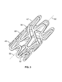
図1および2のステントの3D図を図3に示す。前記周囲形成要素は47、48、および49として記されている。周囲形成要素のペアは47、48であり、前記ペアは複数の第1の連結要素50で連結される。前記ステントの縦軸は50と表示される。周囲形成要素の隣接しあうペア48、49は、第2の連結要素52で連結される。
A 3D view of the stent of FIGS. 1 and 2 is shown in FIG. The surrounding forming elements are marked as 47, 48 and 49. The pair of surrounding forming elements is 47 and 48, and the pair is connected by a plurality of first connecting
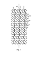
前記連結要素は、前記ステントを平面で切断し、部分的に拡大した図を示した図4に図示するとおり、前記ステントに構造支柱を提供する。前記ステントの縦軸は53と表示される。前記周囲形成要素の一部および前記周囲形成要素の第1および第2の連結要素は、前記ステントの縦軸53に沿って、直線状の支持構造54、55、56を形成する。前記直線状の支持構造は第1の連結要素57、60、63、66、第2の連結要素59、62、65、および前記周囲形成要素の一部58、61、64から形成される。
The connecting element provides structural struts to the stent as illustrated in FIG. 4 which shows a partially enlarged view of the stent cut in a plane. The vertical axis of the stent is displayed as 53. A portion of the perimeter forming element and the first and second connecting elements of the perimeter forming element form a
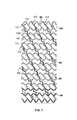
第1および第2の連結要素により形成される、実質的ならせん状構造の別の図を図5に示す。前記ステントの縦軸は67として示される。前記実質的な平行らせん状構造は68、69、および70として示される。前記らせん状構造は、第1の連結要素71、周囲形成要素の一部72、第2の連結要素73、第1の連結要素74、第2の連結要素75、周囲形成要素の一部76、第1の連結要素77、周囲形成要素の一部78、第2の連結要素79、および第1の連結要素80から形成される。ただし、周囲形成要素の一部と散在した連結要素の順序は説明の目的でのみ提供され、他の順序も本発明に含まれる。
Another view of the substantially helical structure formed by the first and second coupling elements is shown in FIG. The longitudinal axis of the stent is shown as 67. The substantially parallel helical structure is shown as 68, 69, and 70. The helical structure comprises a first connecting
図6は、周囲形成要素の隣接しあうペア間の連結要素、つまり、前記第2の連結要素が異なる形状を示す実施形態を示している。この実施形態においては、前記第2の連結要素、つまり、周囲形成要素の隣接しあうペア間の連結要素が曲線状に示される。特に、前記ステントの縦軸は81として示される。周囲形成要素のペア82〜89は、曲線状の連結要素、つまり隣接しあうペアを連結する第2の連結要素96により連結する。実質的ならせん状構造98は、前記ステント101中、一連の第2の連結要素99、第1の連結要素100、第2の連結要素99などから成る。前記第1および第2の連結要素により形成される、本実施形態のらせん状構造を図7の102〜107に示す。前記らせん状構造102〜107は、前記らせん状構造にわたり、第1の連結要素107、109と第2の連結要素108、110が交互に来ることで形成される。注目すべきことに、この実施形態において、前記第1の連結要素が周囲形成要素のペアの隣接しあう山すべてに連結するが、前記第2の連結要素は周囲形成要素の隣接しあうペアの第3の山および谷すべてに連結する。
FIG. 6 shows an embodiment in which the connecting elements between adjacent pairs of surrounding forming elements, ie the second connecting elements, have different shapes. In this embodiment, the second connecting element, ie the connecting element between adjacent pairs of surrounding forming elements, is shown in a curved line. In particular, the longitudinal axis of the stent is shown as 81. The pair of surrounding forming
いくつかの実施形態において、前記曲線状の第2の連結要素は柔軟性がある、またはバネ様であり、収縮および拡張することができるようになっている。前記曲線状の第2の連結要素が作られている材料、および/または前記曲線状の第2の連結要素の幾何学的構成、および/またはステントは、前記曲線状の第2の連結要素の柔軟性を高める。 In some embodiments, the curved second coupling element is flexible or spring-like so that it can contract and expand. The material from which the curved second coupling element is made and / or the geometric configuration of the curved second coupling element, and / or the stent, Increase flexibility.
前記曲線状の第2の連結要素のバネ様の性質は、前記ステントの全体的な柔軟性に寄与することができる。例えば、前記曲線状の第2の連結要素のバネ様の性質は、前記ステントの径方向の拡張および/または収縮を促してもよい。場合によっては、前記ステントが縦軸81に対して測定し、縦方向が同一、または実質的に同一(約+/−10%)となるように、このステントが径方向に拡張および/または収縮してもよい。このようにして、ステントの径方向の収縮または拡張は、前記ステントの縦方向の収縮または拡張に比例して考え、実質的に大きくてもよい。 The spring-like nature of the curved second coupling element can contribute to the overall flexibility of the stent. For example, the spring-like nature of the curvilinear second connecting element may facilitate radial expansion and / or contraction of the stent. In some cases, the stent is radially expanded and / or contracted such that the stent is measured relative to the longitudinal axis 81 and the longitudinal direction is the same or substantially the same (about +/− 10%). May be. In this way, the radial contraction or expansion of the stent may be considered in proportion to the longitudinal contraction or expansion of the stent and may be substantially greater.
図8A〜8Eは、図7に示されたステントパターンの様々な部分の拡大図を示している。マーカー点113を含むステント一端の図は、図8Aに示している。前記周囲形成要素のペアは、111、112として表示される。別の周囲形成要素のペアは、図8Bに示される。前記周囲形成要素114、115のペアは、第1の連結要素116〜119により、前記ペアの1つの連結要素114の谷120から他の周囲形成要素115の山121に連結される。ただし、本実施形態の周囲形成要素は互いに同相であるが、前記第1の連結要素は隣接しあう谷および山を接続する。図8Cは、周囲形成要素の隣接しあうペア間の連結の詳細を示している。周囲形成要素の隣接しあうペアの周囲形成要素122、123は、曲線状の第2の連結要素124により連結しており、これは前記2つの周囲形成要素の山125と谷126を連結する。図8Dは、曲線状の第2の連結要素129により連結した周囲形成要素の隣接しあうペア間の周囲形成要素127、128の別の拡大図を示している。前記周囲形成要素127、128の波状形状により形成する角は、130、131として示されている。図8Eは、周囲形成要素のペア132、133の拡大図を示している。前記周囲形成要素は第1の連結要素134〜136により連結している。前記周囲形成要素および連結要素により形成した多角形のセルは、136、137、134、138、139、135、140として示される。
8A-8E show enlarged views of various portions of the stent pattern shown in FIG. A view of one end of the stent including the marker points 113 is shown in FIG. 8A. The pair of surrounding forming elements is displayed as 111,112. Another pair of surrounding forming elements is shown in FIG. 8B. The pair of surrounding forming
図9に示されるとおり、周囲形成要素ペアの周囲形成要素間の第1の連結要素の数は変化させることができる。示される実施形態において、周囲形成要素のペアが141〜148と表示されている(前記ステントの縦軸149)。1つのペア143に焦点を当て、その周囲形成要素は150、151と表示される。第1の連結要素152〜154は、2つの周囲形成要素を連結して示される。これまでの実施形態とは対照的に、第1の連結要素の数は3であるが、示される他の実施形態において、第1の連結要素の数は6である。第1の結合要素152〜154は、周囲形成要素を形成する1つおきの波状形状に均等に離間する。つまり、前記第1の連結要素との接触点間の波状形状が155、156、157、158、および159である。前記ステント周囲の第1の連結要素の径方向間隔は、例えば0°、120°、240°で均等とすることができる。この実施形態において、前記ステントの一端141、148の周囲形成要素のペアが、第1の連結要素を6個有する。
As shown in FIG. 9, the number of first connecting elements between the surrounding forming elements of the surrounding forming element pair can vary. In the embodiment shown, pairs of surrounding forming elements are labeled 141-148 (
前記ステントが径方向に拡張すると、周囲形成要素の隣接しあうペア間の距離が増加するが、ペア内の周囲形成要素間の距離は減少する。図10A〜10Cにはステントが図示され、切断したステント(A)、および拡張したステント(BおよびC)の三次元図を示している。周囲形成要素のペアは160〜167として図示される。選択された第2の連結要素169〜170および選択された第1の連結要素172は説明の目的でのみ記されている。前記ステントが径方向に拡張すると、前記曲線状の第2の連結要素が真っ直ぐに伸び、10Aの168を見ると、周囲形成要素160、161の隣接しあうペア間の距離が増加することで、三重らせん168、171、および173が形成する。図10Bでは前記第1および第2の連結要素により形成した三重らせんを図示しているが、第1および第2の連結要素の数によって、2つ以上のらせん状構造を有するステントが形成してもよい。
As the stent expands radially, the distance between adjacent pairs of surrounding forming elements increases, but the distance between surrounding forming elements in the pair decreases. 10A-10C illustrate a stent, showing a three-dimensional view of a cut stent (A) and expanded stents (B and C). A pair of surrounding forming elements is illustrated as 160-167. The selected second coupling elements 169-170 and the selected
前記連結要素は少なくとも1つの放射線不透過性マーカーを含んでもよい。当該分野で周知の放射線不透過性マーカーの設計および構成の評価については、www<dot>nitinol−europe<dot>com/pdfs/stentdesign<dot>pdfを参照。前記放射線不透過性マーカーは、多種多様なサイズおよび形状をとる。例えば、放射線不透過性マーカーには、中央に配置されたマーカー用の穴を含めることができる。前記マーカー用の穴は円形または半円形にできるが、他の形状をとることもでき、例えば前記周囲の一部に配置された押出成形部またはディンプル加工部を伴う半円形の穴、またはハート形状の穴などがある。 The connecting element may include at least one radiopaque marker. For evaluation of radiopaque markers design and construction well known in the art, see www <dot> nitinol-europe <dot> com / pdfs / sentdesign <dot> pdf. The radiopaque markers take a wide variety of sizes and shapes. For example, a radiopaque marker can include a centrally located marker hole. The marker hole can be circular or semi-circular, but can take other shapes, for example, a semi-circular hole with an extruded or dimpled portion located in the periphery, or a heart shape There are holes.
前記放射線不透過性マーカーは、電子密度の高い、またはX線を屈折させるマーカー、例えば金属粒子または塩であってもよい。適切なマーカー金属の非限定的な例としては、鉄、金、コロイド銀、亜鉛、およびマグネシウムの純粋な形態または有機化合物のどちらかなどがある。他の放射線不透過性材料は、タンタル、タングステン、プラチナ/イリジウム、またはプラチナである。重金属および重希土類元素は、種々の化合物、例えば第一鉄塩、有機ヨウ素物質、ビスマスまたはバリウム塩などにおいて有用である。利用可能なさらに別の実施形態としては、架橋剤によりさらに架橋結合が可能な、自然鉄粒子が内包された、例えばフェリチンなどがある。フェリチンゲルは、低濃度(0.1〜2%)のグルタルアルデヒドとの架橋結合により調製できる。前記放射線不透過性マーカーは、1若しくはそれ以上の生物分解性ポリマー、例えばPLLA、PDLA、PLGA、PEGなどの結合剤で構成される。放射線不透過性マーカーを有する一実施形態では、鉄を含有する化合物または鉄粒子をPLAポリマーマトリックスに内包させてペースト状の物質を生成し、これを前記ステントに含まれる中空のレセプタクル(容器)に注入し、または入れることができる。 The radiopaque marker may be a marker having a high electron density or refracting X-rays, such as metal particles or a salt. Non-limiting examples of suitable marker metals include either pure forms of iron, gold, colloidal silver, zinc, and magnesium or organic compounds. Other radiopaque materials are tantalum, tungsten, platinum / iridium, or platinum. Heavy metals and heavy rare earth elements are useful in various compounds such as ferrous salts, organic iodine materials, bismuth or barium salts. Yet another embodiment that can be utilized is, for example, ferritin, in which natural iron particles are encapsulated that can be further cross-linked by a cross-linking agent. Ferritin gels can be prepared by cross-linking with low concentrations (0.1-2%) of glutaraldehyde. The radiopaque marker is composed of a binder such as one or more biodegradable polymers such as PLLA, PDLA, PLGA, PEG. In one embodiment having a radiopaque marker, a compound containing iron or iron particles is encapsulated in a PLA polymer matrix to produce a paste-like material, which is placed in a hollow receptacle (container) contained in the stent. Can be injected or filled.
前記ステントは、前記端部ゾーンと前記本体間に移行ゾーンを有することもできる。この移行ゾーンは複数の波状形状から形成でき、各波状形状は、ループにより連結された2つの隣接しあう支柱を有し、前記ループの幅は、当該移行ゾーン全体にわたり変化する。この移行ゾーンは、複数の多角形を有することができ、当該移行ゾーン内で隣接しあう多角形の表面積は、周囲に沿って増加する。米国特許公開第20110125251号。前記移行ゾーンは、他の適切な構成の形態をとってもよい。 The stent may also have a transition zone between the end zone and the body. The transition zone can be formed from a plurality of undulating shapes, each undulating shape having two adjacent struts connected by a loop, the width of the loop varying throughout the transition zone. The transition zone can have a plurality of polygons, and the surface area of the polygons that are adjacent in the transition zone increases along the perimeter. US Patent Publication No. 201110125251. The transition zone may take the form of other suitable configurations.
前記ステントの寸法は場合により異なり、長さ約10mm〜約300mm、長さ20mm〜約300mm、長さ約40mm〜約300mm、長さ約20mm〜約200mm、長さ約60mm〜約150mm、または長さ約80mm〜約120mmである。一実施形態では、前記ステントを長さ約88.9mmとできる。前記ステントの内径(internal diameter:I.D.)の範囲は、約2mm〜約25mm、約2mm〜約5mm(例えば、冠動脈用)、約4mm〜約8mm(例えば、CNSにおける神経のための空間用、血管および非血管の双方)、約6mm〜約12mm(例えば、腸骨大腿用)、約10mm〜約20mm(例えば、腸骨動脈用)、および約10mm〜約25mm(例えば、大動脈用)とすることができる。 The dimensions of the stent may vary from length to about 10 mm to about 300 mm, length 20 mm to about 300 mm, length about 40 mm to about 300 mm, length about 20 mm to about 200 mm, length about 60 mm to about 150 mm, or length The length is about 80 mm to about 120 mm. In one embodiment, the stent can be about 88.9 mm in length. The stent has an internal diameter (ID) range of about 2 mm to about 25 mm, about 2 mm to about 5 mm (eg, for coronary arteries), about 4 mm to about 8 mm (eg, space for nerves in the CNS) , Both vascular and non-vascular), about 6 mm to about 12 mm (eg, for the iliac femur), about 10 mm to about 20 mm (eg, for the iliac artery), and about 10 mm to about 25 mm (eg, for the aorta) It can be.
本発明の装置は、自己拡張型ステントとして使用でき、または米国特許第6,168,617号、第6,222,097号、第6,331,186号、および第6,478,814号に説明されているバルーンカテーテルステント送達システムを含む任意のバルーンカテーテル送達システムと併用できる。一実施形態において、本装置は、米国特許第7,169,162号で開示されたバルーンカテーテルシステムと併用できる。 The device of the present invention can be used as a self-expanding stent or in US Pat. Nos. 6,168,617, 6,222,097, 6,331,186, and 6,478,814. It can be used with any balloon catheter delivery system, including the balloon catheter stent delivery system described. In one embodiment, the device can be used with the balloon catheter system disclosed in US Pat. No. 7,169,162.
本発明の装置は、任意の適切なカテーテルと併用でき、そのカテーテルの口径範囲は、約0.8mm〜約5.5mm、約1.0mm〜約4.5mm、約1.2mm〜約2.2mm、または約1.8〜約3mmとできる。一実施形態において、前記カテーテルは、口径約6フレンチ(2mm)である。別の実施形態において、前記カテーテルは、口径約5フレンチ(1.7mm)である。 The device of the present invention can be used in conjunction with any suitable catheter, the caliber ranges of which are from about 0.8 mm to about 5.5 mm, from about 1.0 mm to about 4.5 mm, from about 1.2 mm to about 2. It can be 2 mm, or about 1.8 to about 3 mm. In one embodiment, the catheter is about 6 French (2 mm) in diameter. In another embodiment, the catheter is about 5 French (1.7 mm) in diameter.
前記ステントは、任意の管または体腔の内腔に挿入でき、その内腔断面を拡張させる。本発明は、任意の動脈、静脈、導管、または他の管、例えば尿管または尿道で展開でき、冠動脈、鼠径下動脈、大動脈腸骨動脈、鎖骨下動脈、腸間膜動脈、または腎動脈を含む任意の動脈の狭窄化または狭窄を治療する上で使用できる。他種の管閉塞、例えば解離性動脈瘤により生じるものも、本発明に含まれる。 The stent can be inserted into the lumen of any tube or body cavity, expanding its lumen cross section. The present invention can be deployed in any artery, vein, conduit, or other tube, such as the ureter or urethra, to coronary, inguinal, aortoiliac, subclavian, mesenteric, or renal arteries. It can be used to treat any arterial stenosis or stenosis including. Other types of vascular occlusions such as those caused by dissecting aneurysms are also included in the present invention.
本発明のステントおよび方法を使って治療可能な対象は、ヒト、ウマ、イヌ、ネコ、ブタ、ウサギ、げっ歯類、サルなどを含む哺乳類である。 Subjects that can be treated using the stents and methods of the present invention are mammals including humans, horses, dogs, cats, pigs, rabbits, rodents, monkeys and the like.
本発明のステントは、広範囲の種々のポリマーを代表する少なくとも1つの生体吸収性ポリマーから成形される。通常、生体吸収性ポリマーは、ラクチド骨格をベースとした脂肪族ポリエステルを有し、これにはポリL−ラクチド、ポリD−ラクチド、ポリD,L−ラクチド、メソラクチド、グリコリド、ラクトン(ホモポリマーまたはコポリマーとしてのほか、コモノマーを伴うコポリマー部分(moiety)に形成されたものとして、例えば、トリメチレンカーボネート(trimethylene carbonate:TMC)、またはε−カプロラクトン(ε−caprolactone:ECL))などがある。米国特許第6,706,854号および第6,607,548号;EP 0401844;およびJeonらの「Synthesis and Characterization of Poly(L−lactide)−Poly(ε−caprolactone)」(ポリ(L−ラクチド)−ポリ(ε−カプロラクトン)の合成および特徴付け)、Multiblock Copolymers Macromolecules 2003年:36、5585〜5592。前記コポリマーは、十分な長さのL−ラクチドまたはD−ラクチドなどの部分を有することで当該コポリマーが結晶化でき、グリコリド、ポリエチレングリコール(polyethylene glycol:PEG)、ε−カプロラクトン、トリメチレンカーボネート、またはモノメトキシ基を末端に有するPEG(monomethoxy−terminated PEG:PEG−MME)の存在による立体障害を受けない。例えば、10、100、または250を超える一定の実施形態では、LまたはD−ラクチドをポリマー内で順次配列できる。また、前記ステントは、生体吸収性ポリマー組成物、例えば米国特許第7,846,361号で開示されたもの、ならびに本出願人の同時係属米国特許公開第2010/0093946号から構成できる。 The stent of the present invention is molded from at least one bioabsorbable polymer representing a wide variety of polymers. Usually, the bioabsorbable polymer comprises an aliphatic polyester based on a lactide backbone, which includes poly L-lactide, poly D-lactide, poly D, L-lactide, mesolactide, glycolide, lactone (homopolymer or In addition to the copolymer, examples of a copolymer formed with a comonomer include trimethylene carbonate (TMC) or ε-caprolactone (ECL). U.S. Pat. Nos. 6,706,854 and 6,607,548; EP 0401844; and Jeon et al., "Synthesis and Characterisation of Poly (L-lactide) -Poly (ε-caprolactone)" (poly (L-lactide)). ) -Synthesis and characterization of poly (ε-caprolactone)), Multiblock Polymers Macromolecules 2003: 36, 5585-5592. The copolymer can be crystallized by having a sufficiently long portion such as L-lactide or D-lactide, such as glycolide, polyethylene glycol (PEG), ε-caprolactone, trimethylene carbonate, or It does not suffer from steric hindrance due to the presence of PEG having a monomethoxy group at its terminal (monomethoxy-terminated PEG: PEG-MME) For example, in certain embodiments above 10, 100, or 250, L or D-lactide can be sequentially arranged within the polymer. The stent may also comprise a bioabsorbable polymer composition, such as that disclosed in US Pat. No. 7,846,361, as well as applicant's co-pending US Patent Publication No. 2010/0093946.
ここで、以下の命名法を、前記モノマータイプの存在に基づく前記ポリマー命名法と併用していく。
LPLA:ポリ(L−ラクチド)
LPLA−PEG:ポリ(ポリ−L−ラクチド−ポリエチレングリコール)
DPLA:ポリ(D−ラクチド)
DPLA−TMC:ポリ(ポリ−D−ラクチド−コ−トリメチレンカーボネート)
DLPLA:ポリ(DL−ラクチド)、ラセミ体コポリマーD−コ−L−ラクチド
LDPLA:ポリ(L−コ−D−ラクチド)
LDLPLA:ポリ(L−コ−DL−ラクチド)、モノマー導入法により命名
PGA:ポリ(グリコシド)
PDO:ポリ(ジオキサン)(商標はPDS)
SR:「自己強化」(処理方法)
TMC:トリメチレンカーボネート
PCL:ポリ(ε−カプロラクトン)
LPLA−TMC:ポリ(ポリL−ラクチド−コ−トリメチレンカーボネート)
LPLG:ポリ(L−ラクチド−コ−グリコシド)
POE:ポリオルトエストル
Here, the following nomenclature is used in combination with the polymer nomenclature based on the presence of the monomer type.
LPLA: Poly (L-lactide)
LPLA-PEG: poly (poly-L-lactide-polyethylene glycol)
DPLA: Poly (D-lactide)
DPLA-TMC: poly (poly-D-lactide-co-trimethylene carbonate)
DLPLA: poly (DL-lactide), racemic copolymer D-co-L-lactide LDPLA: poly (L-co-D-lactide)
LDLPLA: poly (L-co-DL-lactide), named by monomer introduction method PGA: poly (glycoside)
PDO: Poly (dioxane) (Trademark is PDS)
SR: “self-strengthening” (processing method)
TMC: trimethylene carbonate PCL: poly (ε-caprolactone)
LPLA-TMC: poly (poly L-lactide-co-trimethylene carbonate)
LPLG: poly (L-lactide-co-glycoside)
POE: Polyorestor
本発明の一実施形態において、前記組成物は、ポリ(L−ラクチド)またはポリ(D−ラクチド)の塩基性ポリマーを有する。有利な塩基性ポリマー組成物としては、ポリ(L−ラクチド)およびポリ(D−ラクチド)の混合物などがある。他の有利な塩基性ポリマー組成物としては、D,L−ラクチドコモノマーモル比10〜30%のポリ(L−ラクチド−コ−D,L−ラクチド)またはポリ(D−ラクチド−コ−D,L−ラクチド)、グリコリドコモノマーモル比10〜20%のポリ(L−ラクチド−コ−グリコリド)またはポリ(D−ラクチド−コ−グリコリド)などがある。 In one embodiment of the invention, the composition comprises a basic polymer of poly (L-lactide) or poly (D-lactide). Advantageous basic polymer compositions include mixtures of poly (L-lactide) and poly (D-lactide). Other advantageous basic polymer compositions include poly (L-lactide-co-D, L-lactide) or poly (D-lactide-co-D, with a D, L-lactide comonomer molar ratio of 10-30%. L-lactide), poly (L-lactide-co-glycolide) or poly (D-lactide-co-glycolide) having a molar ratio of glycolide comonomer of 10 to 20%.
別の実施形態は、ポリ(L−ラクチド)部分、および/またはポリ(D−ラクチド)部分を備えた塩基性ポリマーをその修飾コポリマーに結合させたものを具体化し、これには、ポリ(L−ラクチド−コ−トリメチレンカーボネート)またはポリ(D−ラクチド−コ−トリメチレンカーボネート)および(L−ラクチド−ε−カプロラクトン)、またはポリ(D−ラクチド−コ−ε−カプロラクトン)であって、ブロックコポリマーまたはブロック型(blocky)ランダムコポリマーの形態のものが含まれ、その場合、ラクチド鎖長は、部分を越えた(cross−moiety)結晶化をもたらす上で十分である。 Another embodiment embodies a poly (L-lactide) moiety and / or a basic polymer with a poly (D-lactide) moiety attached to the modified copolymer, which includes poly (L -Lactide-co-trimethylene carbonate) or poly (D-lactide-co-trimethylene carbonate) and (L-lactide-ε-caprolactone), or poly (D-lactide-co-ε-caprolactone), Included are those in the form of block copolymers or blocky random copolymers, where the lactide chain length is sufficient to result in cross-moiety crystallization.
別の実施形態において、前記ポリマー組成物は、LおよびD部分の前記ラクチドラセミ体(ステレオ複合体)結晶構造の生成を可能にして前記生体吸収性ポリマー医療装置の機械的特性をさらに強化する。前記ラセミ体(ステレオ複合体)結晶構造の形成は、以下の組み合わせなどの配合物から生じさせることができる。
ポリL−ラクチド、ポリD−ラクチド、およびポリL−ラクチド−コ−TMC;
ポリD−ラクチドおよびポリL−ラクチド−コ−TMC;
ポリL−ラクチドおよびポリD−ラクチド−コ−TMC;
ポリL−ラクチド、ポリD−ラクチド、およびポリD−ラクチド−コ−TMC;
ポリL−ラクチド−コ−PEGおよびポリD−ラクチド−コ−TMC;
ポリD−ラクチド−コ−PEGおよびポリL−ラクチド−コ−TMC
In another embodiment, the polymer composition further enhances the mechanical properties of the bioabsorbable polymer medical device by allowing the generation of the lactidol semi (stereocomplex) crystal structure of the L and D moieties. Formation of the racemic (stereocomplex) crystal structure can occur from a formulation such as the following combinations.
Poly L-lactide, poly D-lactide, and poly L-lactide-co-TMC;
Poly D-lactide and poly L-lactide-co-TMC;
Poly L-lactide and poly D-lactide-co-TMC;
Poly L-lactide, poly D-lactide, and poly D-lactide-co-TMC;
Poly L-lactide-co-PEG and poly D-lactide-co-TMC;
Poly-D-lactide-co-PEG and poly-L-lactide-co-TMC
本実施形態のポリ−ラクチドラセミ体組成物は、熱を加えることなく「低温で成形可能または曲げ可能である」という特に有利な特徴を有することができる。本発明の、低温で曲げられる骨組みは、キャリア装置にクリンプし、または不規則形状の器官空間に対応する上で十分柔軟になるための外力を必要としない。低温で曲げられる周囲温度は、30℃を超えない室温と定義される。低温で曲げられる骨組みは、例えば、器官空間、例えば脈動する血管の内腔に留置された場合、拡張された骨組み装置に十分な柔軟性をもたらす。例えば、ステントについては、製造後に大部分が非結晶性ポリマー部分であり、前記入れ子にされ若しくは端部に配置された二次的な蛇行する支柱が、前記骨組みが、留置のためのバルーン膨張時の伸長によりひずんだとき、特に結晶化可能なポリマー組成物を利用することが望ましい。そのような低温で曲げられるポリマーの骨組みに関する実施形態は、脆性ではなく、曲線的表面を有する体内空間への留置前に柔軟な状態にするための予熱も不要である。低温曲げにより、これらの混合物はひび割れすることなく室温でクリンプでき、さらに、ひび割れすることなく生理学的条件で拡張可能である。 The poly-lactide racemic composition of this embodiment can have the particularly advantageous feature of being “moldable or bendable at low temperatures” without the application of heat. The low temperature bendable skeleton of the present invention does not require external forces to be crimped to a carrier device or to be sufficiently flexible to accommodate irregularly shaped organ spaces. Ambient temperature bent at low temperature is defined as room temperature not exceeding 30 ° C. Skeletons that are bent at low temperatures, for example, provide sufficient flexibility to an expanded skeleton device when placed in an organ space, such as the lumen of a pulsating blood vessel. For example, for a stent, it is mostly a non-crystalline polymer portion after manufacture, and the secondary serpentine struts that are nested or placed at the ends are used when the skeleton is inflated for balloon deployment. It is desirable to utilize a polymer composition that is particularly crystallizable when distorted by stretching. Such low temperature bendable polymer frameworks are not brittle and do not require preheating to be flexible before placement in a body space having a curved surface. By cold bending, these mixtures can be crimped at room temperature without cracking and can be expanded at physiological conditions without cracking.
本明細書の実施形態のポリラクチドラセミ体組成物および非ラセミ体組成物は、当該混合組成物に耐衝撃性改良剤を加えた場合でも部分を越えた結晶化を可能にするブロック型部分を有するよう処理できる。このような混合物は、1つまたは2つのTg(ガラス溶解転移点)をもたらすことにより、装置固有のポリマー組成物または混合物を設計できる可能性を生む。 The polylactide racemic and non-racemic compositions of the embodiments herein have a block-type portion that allows crystallization beyond the portion even when an impact modifier is added to the mixed composition. Can be processed. Such mixtures give rise to the possibility of designing device-specific polymer compositions or mixtures by providing one or two Tg (glass melting transition points).
ポリラクチドラセミ体組成物は、例えば非ラセミ体PLDL−ラクチド混合物と比べ、再結晶能力を著しく改善できる。異なるポリラクチド部分の有利なラセミ体配列は、例えば、これに限定されるものではないが、必要な留置口径への拡張中の伸長時、異なるポリラクチドステレオ部分(stereomoieties)間でラセミ体結晶を形成できる前記ポリL−ラクチド−コ−TMCコポリマーと、ポリ−D−ラクチドを混合することにより実現される。このひずみに誘発される結晶化は、有害なひび割れを伴うことなく、結果的に機械的特性を高め、ひいては基材ベースのモジュラスデータに望ましい変化をもたらす。 The polylactide racemic composition can significantly improve the recrystallization ability compared to, for example, non-racemic PLDL-lactide mixtures. An advantageous racemic arrangement of different polylactide moieties may form, for example, but not limited to, racemic crystals between different polylactide stereo moieties upon extension during expansion to the required indwelling aperture. This is achieved by mixing the poly L-lactide-co-TMC copolymer and poly-D-lactide. This strain-induced crystallization results in enhanced mechanical properties without detrimental cracks, and thus desirable changes in substrate-based modulus data.
組成物のコポリマーとの部分を超えた結晶化は、モノマーモル比が約90:10〜50:50範囲のコポリマーに限定されるものと見られる。実際、50:50のモル比ではポリマー部分が結晶化に立体障害を及ぼす一方、それを超える比は、部分を越えた結晶化にはるかに適している。実験的に誘発した結晶化、また各種濃度のラクチドコポリマー、例えばTMCとの種々の混合物であって、L−ラクチド成分とのラセミ体配列のため過剰なポリ(D−ラクチド)が加えられたものに基づき、ラセミ体組成物における前記コポリマーの効果的濃度は、40%に等しいかそれ未満である。これを受け、部分間の結晶化により形成される熱的架橋結合は、伸長またはクリープを軽減するとともに、意図された強化機序を維持する役割を果たす。この有利に強靭なラセミ体組成物は、引張試験でモジュラスデータを向上させ、前記ポリマー混合物における引張強度を軽減する方法を回避する。 Crystallization beyond the copolymer portion of the composition appears to be limited to copolymers having a monomer molar ratio in the range of about 90:10 to 50:50. In fact, at a 50:50 molar ratio, the polymer portion has steric hindrance to crystallization, while ratios above that are much more suitable for crystallization beyond the portion. Experimentally induced crystallization and various mixtures with different concentrations of lactide copolymers, such as TMC, with excess poly (D-lactide) added due to racemic alignment with the L-lactide component The effective concentration of the copolymer in the racemic composition is less than or equal to 40%. In response, thermal cross-linking formed by crystallization between the parts serves to reduce elongation or creep and maintain the intended strengthening mechanism. This advantageously tough racemic composition avoids methods of improving modulus data in tensile tests and reducing the tensile strength in the polymer blend.
有利なラセミ体組成物の一実施形態は、高残留モノマーレベルの点から劣化を最低限に抑えた生体吸収性ポリマーを提供し、混入モノマーの残留画分が約0.5%を超えないよう、好ましくは約0.3%を超えないようにする。本発明のポリマーの実施形態におけるモノマー混入濃度は、約0.2%まで低減されている。 One embodiment of an advantageous racemic composition provides a bioabsorbable polymer with minimal degradation in terms of high residual monomer levels so that the residual fraction of contaminating monomers does not exceed about 0.5%. Preferably not exceeding about 0.3%. The monomer contamination concentration in the polymer embodiments of the present invention is reduced to about 0.2%.
本明細書で説明する実施形態のポリマー組成物は、当該組成物に対して約70重量%〜約95重量%、または約70重量%〜約80重量%存在する塩基性ポリマーを有することができる。例えば一実施形態において、前記ポリマー配合物は、約70重量%以上のポリL−ラクチド(約2.5〜3IV)をポリL−ラクチド−コ−TMC(70/30モル比)(1.4〜1.6IV)とともに有することができる。別の実施形態において、前記ポリマー配合物は、70重量%のトリブロックポリL−ラクチド−コ−PEG(99/01モル比)(2.5〜3IV)をポリL−ラクチド−コ−TMC(70/30モル比)(1.4〜1.6IV)とともに有することができる。さらに、前記ポリマー配合物は、約70重量%のジブロックポリL−ラクチド−コ−PEG−MME(95/05モル比)(2.5〜3IV)およびポリL−ラクチド−コ−TMC(70/30モル比)(1.4〜1.6IV)の配合物を有することができる。他の実施形態では、組成物中でε−カプロラクトンが上述のTMCと置き換えられた配合物を提供する。同様に、一実施形態では、PEG−MMEをPEGと置換できる配合物を提供できる。 The polymer composition of the embodiments described herein can have a basic polymer present from about 70% to about 95%, or from about 70% to about 80% by weight relative to the composition. . For example, in one embodiment, the polymer blend comprises about 70% or more poly L-lactide (about 2.5-3IV) by poly L-lactide-co-TMC (70/30 molar ratio) (1.4. ~ 1.6IV). In another embodiment, the polymer blend comprises 70 wt% triblock poly L-lactide-co-PEG (99/01 molar ratio) (2.5-3IV) with poly L-lactide-co-TMC ( 70/30 molar ratio) (1.4-1.6 IV). Further, the polymer blend comprises about 70% by weight diblock poly L-lactide-co-PEG-MME (95/05 molar ratio) (2.5-3IV) and poly L-lactide-co-TMC (70 / 30 molar ratio) (1.4-1.6 IV). In other embodiments, a formulation is provided in which ε-caprolactone is replaced with the TMC described above in the composition. Similarly, in one embodiment, a formulation that can replace PEG-MME with PEG can be provided.
当該分野で理解されているように、本発明のポリマー組成物は、選ばれた医療装置の種々の要件に対応するようカスタマイズできる。それらの要件としては、生理学的および局所的な解剖学的条件下での機械的強度、弾性、柔軟性、弾力性、および劣化率などがある。具体的な組成物の付加的な効果は、代謝産物の溶解度、親水性および水の取り込み、そして付着するマトリックスまたは封入される医薬品の放出率に関する。 As is understood in the art, the polymer composition of the present invention can be customized to meet the various requirements of a selected medical device. These requirements include mechanical strength, elasticity, flexibility, elasticity, and rate of degradation under physiological and local anatomical conditions. Additional effects of specific compositions relate to metabolite solubility, hydrophilicity and water uptake, and the rate of release of the adhering matrix or encapsulated pharmaceutical.
前記ポリマーインプラントの実用性は、質量損失、分子量の減少、機械的特性の保持、および/または組織反応を測定することにより評価できる。骨組みとしてより重要な性能は、加水分解安定性、熱転移、結晶化度、および配向である。骨組み性能に悪影響を及ぼす他の決定要因としては、モノマー不純物、環式および非環式オリゴマー、構造的欠陥、および老朽化などがあるが、これに限定されるものではない。 The utility of the polymer implant can be evaluated by measuring mass loss, molecular weight reduction, retention of mechanical properties, and / or tissue response. More important performance as a framework is hydrolytic stability, thermal transition, crystallinity, and orientation. Other determinants that adversely affect skeletal performance include, but are not limited to, monomer impurities, cyclic and acyclic oligomers, structural defects, and aging.
上記のポリマー組成物から作製された医療装置は、押出成形または金型成形の後、非常に非結晶性となる可能性がある。そのような装置は、制御下で再結晶化を行うことにより、結晶化度を漸進的に進め、機械的強度を高めることができる。装置配備時にひずみが導入されると、結晶化をさらに誘発することができる。そのような漸進的再結晶化は、二次的または最終的な製造(例えば、レーザー切断による)前の「ブランク」装置上、またはそのような二次的製造後のどちらかで行える。また、結晶化(したがって機械的特性)は、付加的な製造加工前に、ポリマーチューブ、中空繊維、シートまたは膜、あるいはモノフィラメントの「冷間」引き抜きなどでひずみを導入することにより、最大限に伸ばすことができる。結晶化度は、前記医療装置の剛性強化に寄与することが認められている。そのため、前記骨組みのポリマー組成物および立体複合体は、非結晶性およびパラ結晶性双方の部分を有する。初期に半結晶性であったポリマー部分は、所定の装置を伸長または拡張して操作できる。しかし、前記ポリマー装置の柔軟性および弾性を達成するには、十分な量の非結晶性ポリマー特性が望まれる。通常のモノマー成分としては、ラクチド、グリコリド、カプロラクトン、ジオキサノン、およびトリメチレンカーボネートなどがある。また、前記ステントは、生体吸収中に前記ポリマー構造上で灌流し、これに作用する局所組織または循環器の生物活性因子および酵素に対し、比較的均一な露出を実現するよう構成されている。 Medical devices made from the polymer compositions described above can become very amorphous after extrusion or molding. Such an apparatus can progressively increase the crystallinity and increase the mechanical strength by performing recrystallization under control. If strain is introduced during device deployment, crystallization can be further induced. Such gradual recrystallization can be performed either on a “blank” device before secondary or final manufacturing (eg, by laser cutting) or after such secondary manufacturing. Crystallization (and therefore mechanical properties) can be maximized by introducing strain, such as “cold” drawing of polymer tubes, hollow fibers, sheets or membranes, or monofilaments, before additional manufacturing processing. Can be stretched. It has been observed that crystallinity contributes to the rigidity enhancement of the medical device. Therefore, the framework polymer composition and steric complex have both amorphous and paracrystalline portions. The polymer portion that was initially semi-crystalline can be manipulated by stretching or expanding a given device. However, a sufficient amount of amorphous polymer properties is desired to achieve the flexibility and elasticity of the polymer device. Common monomer components include lactide, glycolide, caprolactone, dioxanone, and trimethylene carbonate. The stent is also configured to achieve relatively uniform exposure to local tissue or cardiovascular bioactive factors and enzymes that perfuse over and act on the polymer structure during bioabsorption.
有利なことに、器官空間インプラント、例えば心臓血管ステントの前記ポリマーマトリックスのin situ分解反応速度は、組織の過負荷、炎症反応、または他の比較的有害な影響を回避する上で十分緩やかである。一実施形態において、前記骨組みは、少なくとも1か月存続するよう製造される。 Advantageously, the in situ degradation kinetics of the polymer matrix of organ space implants, such as cardiovascular stents, are slow enough to avoid tissue overload, inflammatory reactions, or other relatively harmful effects . In one embodiment, the skeleton is manufactured to last at least one month.
前記ポリマーには、例えば当該ポリマーの活性部位にグラフト重合またはコーティングを行うことにより、医薬組成物を導入できる。本発明に係るポリマーの一実施形態では、前記ポリマーマトリックスまたはポリマーコーティングに生体治癒因子または他の薬剤を付着させ、または導入することが可能である。 A pharmaceutical composition can be introduced into the polymer, for example, by performing graft polymerization or coating on the active site of the polymer. In one embodiment of the polymer according to the present invention, a biohealing factor or other drug can be attached to or introduced into the polymer matrix or polymer coating.
別の実施形態では、前記ポリマーマトリックスに薬剤を構造的に封入し、または付着させるよう前記組成物を構成できる。そのような添加剤の目的は、例えばステントについては、前記医療装置ポリマーが接触する心臓血管系または血管部位の治療を提供することである。前記ポリマーにおける薬剤の封入または付着の種類は、前記装置からの放出率を左右する。例えば、前記ポリマーマトリックスには、これに限定されるものではないが、共有結合、非極性結合のほか、エステルまたは同様な生体可逆性結合手段を含む種々の既知の方法で、前記薬剤または他の添加剤を結合させることができる。 In another embodiment, the composition can be configured to structurally encapsulate or attach a drug to the polymer matrix. The purpose of such additives is, for example, for stents, to provide treatment of the cardiovascular system or site where the medical device polymer contacts. The type of drug encapsulation or attachment in the polymer will determine the rate of release from the device. For example, the polymer matrix may be a variety of known methods including, but not limited to, covalent bonds, non-polar bonds, as well as esters or similar bioreversible binding means, such as, but not limited to, the drug or other Additives can be combined.
一実施形態において、生体吸収性の体内留置可能な医療装置は、1若しくはそれ以上の障壁層を含む生物分解性および生体吸収性のコーティングで覆うことができ、前記ポリマーマトリックスは、以上に述べた医薬物質のうち1若しくはそれ以上を含む。この実施形態において、前記障壁層は、以下を含む適切な生物分解性ポリマーを含む適切な生物分解性材料を有することができるが、これに限定されるものではない:ポリエステル、例えばPLA、PGA、PLGA、PPF、PCL、PCC、TMC、およびこれらの任意のコポリマー;ポリカルボン酸、無水マレイン酸ポリマーを含むポリ無水物;ポリオルトエステル;ポリアミノ酸;ポリエチレンオキシド;polyphosphacenes;ポリ乳酸、ポリグリコール酸とそのコポリマーおよび混合物、例えばポリ(L−乳酸)(PLLA)、ポリ(D,L−ラクチド)、ポリ(乳酸−コ−グリコール酸)、50/50(DL−ラクチド−コ−グリコリド);polydixanone;ポリプロピレンフマラート;ポリデプシペプチド;ポリカプロラクトンとそのコポリマーおよび混合物、例えばポリ(D,L−ラクチド−コ−カプロラクトン)およびポリカプロラクトン−コ−ブチルアクリル酸;吉草酸ポリヒドロキシブチラートとその混合物;ポリカーボネート、例えばチロシン由来のポリカーボネートおよびアリール化物(arylates)、ポリイミノカーボネート、およびポリジメチルトリメチルカーボネート;シアノアクリレート;リン酸カルシウム;ポリグリコサミノグリカン;巨大分子、例えば多糖類(ヒアルロン酸;セルロース、およびヒドロキシプロピルメチルセルロース;ゼラチン;デンプン;デキストラン;アルギン酸塩とその誘導体を含む)、タンパク質、およびポリペプチド;ならびに以上のいずれかの混合物およびコポリマー。また、前記生物分解性ポリマーは、表面侵食可能なポリマー、例えばポリヒドロキシブチラートとそのコポリマー、ポリカプロラクトン、ポリ無水物(結晶性および非結晶性の双方)、無水マレイン酸コポリマー、およびリン酸亜鉛カルシウムとすることもできる。装置上のポリマーの骨組みが有することのできる障壁層の数は、患者の治療に必要とされる量に応じて異なる。例えば、治療が長期的になるほど、その期間中に必要とされる治療用の物質、医薬物質を適切なタイミングで提供するための障壁層の数も増える。 In one embodiment, a bioabsorbable indwellable medical device can be covered with a biodegradable and bioabsorbable coating that includes one or more barrier layers, the polymer matrix described above. Contains one or more of the medicinal substances. In this embodiment, the barrier layer can have a suitable biodegradable material including a suitable biodegradable polymer including, but not limited to: polyesters such as PLA, PGA, PLGA, PPF, PCL, PCC, TMC, and any copolymers thereof; polyanhydrides including polycarboxylic acids, maleic anhydride polymers; polyorthoesters; polyamino acids; polyethylene oxides; polyphosphacenes; and polylactic acid, polyglycolic acid Its copolymers and mixtures such as poly (L-lactic acid) (PLLA), poly (D, L-lactide), poly (lactic acid-co-glycolic acid), 50/50 (DL-lactide-co-glycolide); Polypropylene fumarate; polydepsipe Polycaprolactone and copolymers and mixtures thereof such as poly (D, L-lactide-co-caprolactone) and polycaprolactone-co-butylacrylic acid; valeric acid polyhydroxybutyrate and mixtures thereof; polycarbonates such as polycarbonates derived from tyrosine And arylates, polyiminocarbonates, and polydimethyltrimethyl carbonates; cyanoacrylates; calcium phosphates; polyglycosaminoglycans; macromolecules such as polysaccharides (hyaluronic acid; cellulose and hydroxypropyl methylcellulose; gelatin; starch; dextran Alginate and its derivatives), proteins, and polypeptides; and mixtures and copolymers of any of the foregoing. The biodegradable polymer may also be a surface erodible polymer such as polyhydroxybutyrate and copolymers thereof, polycaprolactone, polyanhydrides (both crystalline and non-crystalline), maleic anhydride copolymers, and zinc phosphate It can also be calcium. The number of barrier layers that the polymer framework on the device can have depends on the amount required to treat the patient. For example, the longer the treatment, the greater the number of barrier layers required to provide the therapeutic and pharmaceutical substances needed at that time.
別の実施形態において、前記ポリマー組成物中の前記添加剤は、前記マトリックス内の複数成分の医薬組成物の形態にでき、例えば早期の新生内膜過形成または平滑筋細胞の遊走および増殖を遅延させる持続放出医薬製剤および管の開存性を保つ長時間作用型の薬剤または血管径をリモデリングさせる陽性薬剤を放出する二次的な生体内安定性のマトリックス、例えば血管内皮型一酸化窒素合成酵素(endothelial nitric oxide synthase:eNOS)、一酸化窒素供与体とその誘導体、例えばアスピリンまたはその誘導体、一酸化窒素生成ヒドロゲル、PPAR作動薬、例えばPPAR−α gands、組織プラスミノーゲン活性化因子、スタチン、例えばアトルバスタチン、エリスロポエチン、darbepotin、セリンプロテイナーゼ−1(serine proteinase−1:SERP−1)およびプラバスタチン、ステロイド、および/または抗生物質を含む。 In another embodiment, the additive in the polymer composition can be in the form of a multi-component pharmaceutical composition within the matrix, for example, to delay early neointimal hyperplasia or smooth muscle cell migration and proliferation. Sustained-release pharmaceutical formulations and long-acting drugs that preserve patency of the tube or secondary biostable matrices that release positive drugs that remodel blood vessel diameter, such as vascular endothelial nitric oxide synthesis Enzymes (endothelial oxide synthase: eNOS), nitric oxide donors and derivatives thereof, such as aspirin or derivatives thereof, nitric oxide-generating hydrogels, PPAR agonists, such as PPAR-α gands, tissue plasminogen activator, statins Eg atorvastatin, erythropoietin, darb epotin, serine proteinase-1 (SERP-1) and pravastatin, steroids, and / or antibiotics.
医薬組成物は、前記ポリマーに導入でき、または前記ポリマーの混合および押出成形後、スプレー、ディッピング、または塗布により、あるいはマイクロカプセル化したのち当該ポリマー混合物に混合して、当該ポリマーの表面にコーティングできる。米国特許第6,020,385号。前記医薬組成物は、共有結合により前記ポリマー混合物に結合されるとき、ヘテロまたはホモ二官能性架橋剤により結合される(http<colon>//www<dot>piercenet<dot>com/products/browse<dot>cfm?fldID=020306を参照)。 The pharmaceutical composition can be introduced into the polymer or coated on the surface of the polymer after mixing and extruding the polymer, by spraying, dipping or coating, or microencapsulated and then mixed with the polymer mixture. . US Patent No. 6,020,385. When the pharmaceutical composition is bound to the polymer mixture by covalent bonds, it is bound by a hetero- or homobifunctional crosslinker (http <colon> // www <dot> piercenet <dot> com / products / browse). <dot> cfm? see fldID = 020306).
前記ステントに導入でき、または前記ステントにコーティングできる薬剤としては、以下が含まれるが、これに限定されるものではない:(i)(a)ヘパリン、ヘパリン誘導体、ウロキナーゼ、およびPPack(デキストロフェニルアラニン・プロリン・アルギニン・クロロメチルケトン)などの抗血栓薬、(b)デキサメタゾン、プレドニゾロン、コルチコステロン、ブデソニド、エストロゲン、スルファサラジン、およびメサラミンなどの抗炎症薬、(c)パクリタキセル、5−フルオロウラシル、シスプラチン、ビンブラスチン、ビンクリスチン、エポチロン、エンドスタチン、アンギオスタチン、アンギオペプチン、平滑筋細胞の増殖を阻害することのできるモノクローナル抗体、チミジンキナーゼ阻害剤、ラパマイシン、40−0−(2−ヒドロキシエチル)ラパマイシン(エベロリムス)、40−0−ベンジル−ラパマイシン、40−0(4’−ヒドロシメチル)ベンジル−ラパマイシン、40−0−[4’−(1,2−ジヒドロキシエチル)]ベンジル−ラパマイシン、40−アリル−ラパマイシン、40−0−[3’−(2,2−ジメチル−1,3−ジオキソラン−4(S)−イル−プロパ−2’−エン−l’−イル]−20ラパマイシン、(2’:E,4’S)−40−0−(4’,5’.:ジヒドロキシペンタ−2’−エン−1’−イル)ラパマイシン、40−0(2ヒドロキシ)エトキシカルボニルメチル−ラパマイシン、40−0−(3−ヒドロキシプロピル−ラパマイシン、40−0−((ヒドロキシ)ヘキシル−ラパマイシン、40−0−[2−(2−ヒドロキシ)エトキシ]エチル−ラパマイシン、40−0−[(3S)−2,2ジメチルジオキソラン−3−イル]メチル−ラパマイシン、40−0−[(2S)−2,3−ジヒドロキシプロパ−l−イル]−ラパマイシン、40−0−(2−アセトキシ)エチル−ラパマイシン、40−0−(2−ニコチノイルオキシ)エチル−ラパマイシン、40−0−[2−(N−25モルホリノ)アセトキシエチル−ラパマイシン、40−0−(2−N−イミダゾリルアセトキシ)エチル−ラパマイシン、40−0[2−(N−メチル−N’−ピペラジニル)アセトキシ]エチル−ラパマイシン、39−0−デスメチル−3.9,40−0,0エチレン−ラパマイシン、(26R)−26−ジヒドロ−40−0−(2−ヒドロキシ)エチル−ラパマイシン、28−Oメチルラパマイシン、40−0−(2−アミノエチル)−ラパマイシン、40−0−(2−アセトアミノエチル)−ラパマイシン、40−0(2−ニコチンアミドエチル)−ラパマイシン、40−0−(2−(N−メチル−イミダゾ−2’イルカルベトキシアミド)エチル)−30ラパマイシン、40−0−(2−エトキシカルボニルアミノエチル)−ラパマイシン、40−0−(2−トリルスルホンアミドエチル)−ラパマイシン、40−0−[2−(4’,5’−ジカルボエトキシ−l’,2’;3’−トリアゾール−l’−イル)−エチル]ラパマイシン、42−エピ−(テトラゾリル)ラパマイシン(タクロリムス)、および42−[3−ヒドロキシ−2−(ヒドロキシメチル)−2−メチルプロパノエート]ラパマイシン(テムシロリムス)(WO2008/086369)などの抗悪性腫瘍薬/抗増殖薬/抗縮瞳薬、(d)リドカイン、ブピバカイン、およびロピバカインなどの麻酔薬、(e)D−Phe−Pro−Argクロロメチルケトン、RGDペプチド含有化合物、ヘパリン、ヒルジン、アンチトロンビン化合物、血小板受容体拮抗薬、アンチトロンビン抗生剤、抗血小板受容体抗体、アスピリン、プロスタグランジン阻害剤、抗血小板薬、およびマダニ抗血小板ペプチド(tick antiplatelet peptides)などの抗凝固剤、(f)増殖因子、転写活性化因子、および翻訳プロモーターなどの血管細胞増殖プロモーター、(g)増殖因子阻害剤、増殖因子受容体拮抗薬、転写レプレッサー、翻訳レプレッサー、複製阻害剤、抑制抗体、抗増殖因子抗体、増殖因子およびサイトトキシンから成る二機能性分子、抗体およびサイトトキシンから成る二機能性分子などの血管細胞増殖阻害剤、(h)プロテインキナーゼおよびチロシンキナーゼ阻害剤(例えば、チルホスチン、ゲニステイン、キサリン)、(i)プロスタサイクリン類似体、(j)コレステロール降下薬、(k)アンジオポイエチン、(1)トリクロサン、セファロスポリン、アミノグリコシド、およびニトロフラントインなどの抗菌薬、(m)細胞毒性薬、細胞増殖抑制剤、および細胞増殖影響因子、(n)血管拡張剤、および(o)内因性血管作用機序を阻害する薬剤などの薬剤、(ii)アンチセンスDNAおよびRNAのほか、以下のためのDNAコーディングを含む遺伝子治療剤(a)アンチセンスRNA、(b)欠陥または欠損した内因性分子に置き換わるtRNAまたはrRNA、(c)成長因子、例えば酸性および塩基性線維芽細胞成長因子、血管内皮成長因子、上皮成長因子、形質転換成長因子aおよびP、血小板由来の内皮成長因子、血小板由来の成長因子、腫瘍壊死因子、肝細胞成長因子、およびインスリン様成長因子を含む血管新生因子、(d)CD阻害剤を含む細胞周期阻害剤、および(e)チミジンキナーゼ(「TK」)および細胞増殖を妨げる上で有用な他の薬剤。 Agents that can be introduced to or coated on the stent include, but are not limited to: (i) (a) heparin, heparin derivatives, urokinase, and PPack (dextrophenylalanine) (B) Dexamethasone, prednisolone, corticosterone, budesonide, estrogen, sulfasalazine, and mesalamine, (c) paclitaxel, 5-fluorouracil, cisplatin Vinblastine, vincristine, epothilone, endostatin, angiostatin, angiopeptin, monoclonal antibody capable of inhibiting smooth muscle cell proliferation, thymidine kinase inhibitor, rapamycin, 40 0- (2-hydroxyethyl) rapamycin (everolimus), 40-0-benzyl-rapamycin, 40-0 (4′-hydroxymethyl) benzyl-rapamycin, 40-0- [4 ′-(1,2-dihydroxyethyl) Benzyl-rapamycin, 40-allyl-rapamycin, 40-0- [3 ′-(2,2-dimethyl-1,3-dioxolane-4 (S) -yl-prop-2′-en-l′-yl ] -20 rapamycin, (2 ′: E, 4 ′S) -40-0- (4 ′, 5 ′.: Dihydroxypenta-2′-en-1′-yl) rapamycin, 40-0 (2 hydroxy) Ethoxycarbonylmethyl-rapamycin, 40-0- (3-hydroxypropyl-rapamycin, 40-0-((hydroxy) hexyl-rapamycin, 40-0- [2- 2-hydroxy) ethoxy] ethyl-rapamycin, 40-0-[(3S) -2,2dimethyldioxolan-3-yl] methyl-rapamycin, 40-0-[(2S) -2,3-dihydroxyprop-l -Yl] -rapamycin, 40-0- (2-acetoxy) ethyl-rapamycin, 40-0- (2-nicotinoyloxy) ethyl-rapamycin, 40-0- [2- (N-25morpholino) acetoxyethyl- Rapamycin, 40-0- (2-N-imidazolylacetoxy) ethyl-rapamycin, 40-0 [2- (N-methyl-N′-piperazinyl) acetoxy] ethyl-rapamycin, 39-0-desmethyl-3.9, 40-0,0 ethylene-rapamycin, (26R) -26-dihydro-40-0- (2-hydroxy) ethyl-rapa Mycin, 28-O methyl rapamycin, 40-0- (2-aminoethyl) -rapamycin, 40-0- (2-acetaminoethyl) -rapamycin, 40-0 (2-nicotinamidoethyl) -rapamycin, 40- 0- (2- (N-methyl-imidazo-2′ylcarbethoxyamido) ethyl) -30 rapamycin, 40-0- (2-ethoxycarbonylaminoethyl) -rapamycin, 40-0- (2-tolylsulfonamide) Ethyl) -rapamycin, 40-0- [2- (4 ′, 5′-dicarboethoxy-l ′, 2 ′; 3′-triazol-l′-yl) -ethyl] rapamycin, 42-epi- (tetrazolyl) ) Rapamycin (tacrolimus) and 42- [3-hydroxy-2- (hydroxymethyl) -2-methylpropanoate] ra Antineoplastic / antiproliferative / antimiotics such as mycin (temsirolimus) (WO2008 / 086369), (d) anesthetics such as lidocaine, bupivacaine, and ropivacaine, (e) D-Phe-Pro-Arg chloro Methyl ketone, RGD peptide-containing compound, heparin, hirudin, antithrombin compound, platelet receptor antagonist, antithrombin antibiotic, antiplatelet receptor antibody, aspirin, prostaglandin inhibitor, antiplatelet drug, and tick antiplatelet peptide (F) growth factor, transcriptional activator, and vascular cell growth promoter such as translation promoter, (g) growth factor inhibitor, growth factor receptor antagonist, transcriptional repressor , Translation repressor, replication (H) protein kinase and tyrosine kinase inhibition, such as harmful agents, inhibitory antibodies, anti-growth factor antibodies, bifunctional molecules consisting of growth factors and cytotoxins, bifunctional molecules consisting of antibodies and cytotoxins Agents (eg, tyrphostin, genistein, oxaline), (i) prostacyclin analogs, (j) cholesterol-lowering drugs, (k) angiopoietin, (1) triclosan, cephalosporins, aminoglycosides, and nitrofurantoin Agents such as antibacterial agents, (m) cytotoxic agents, cytostatic agents, and cell growth influencing factors, (n) vasodilators, and (o) agents that inhibit endogenous vasoactive mechanisms, (ii) anti In addition to sense DNA and RNA, gene therapy agents (a Antisense RNA, (b) tRNA or rRNA replacing a defective or deficient endogenous molecule, (c) growth factors such as acidic and basic fibroblast growth factor, vascular endothelial growth factor, epidermal growth factor, transforming growth factor a and P, angiogenic factors including platelet-derived endothelial growth factor, platelet-derived growth factor, tumor necrosis factor, hepatocyte growth factor, and insulin-like growth factor, (d) a cell cycle inhibitor including a CD inhibitor, And (e) thymidine kinase (“TK”) and other agents useful in preventing cell proliferation.
前記ステントに導入できる他の薬剤としては、以下が含まれるが、これに限定されるものではない:アカルボース(acarbosc)、抗原、ベータ受容体遮断薬、非ステロイド性抗炎症薬(NSAID)、強心配糖体、アセチルサリチル酸、ウイルス増殖抑制薬、アクラルビシン、アシクロビル、シスプラチン、アクチノマイシン、α−およびβ−交感神経様作用薬(ドメプラゾール(dmeprazole))、アロプリノール、アルプロスタジル、プロスタグランジン、アマンタジン、アンブロキソール、アムロジピン、メトトレキセート、S−アミノサリチル酸、アミトリプチリン、アモキシシリン、アナストロゾール、アテノロール、アザチオプリン、バルサラジド、ベクロメタゾン、ベタヒスチン、ベザフィブラート、ビカルタミド、ジアゼパムおよびジアゼパム誘導体、ブデソニド、ブフェキサマク、ブプレノルフィン、メタドン、カルシウム塩、カリウム塩、マグネシウム塩、カンデサルタン、カルバマゼピン、カプトプリル、セファロスポリン、セチリジン、ケノデオキシコール酸、ウルソデオキシコール酸、テオフィリンおよびテオフィリン誘導体、トリプシン、シメチジン、クラリスロマイシン、クラブラン酸、クリンダマイシン、クロブチノール、クロニジン、コトリモキサゾール、コデイン、カフェイン、ビタミンDおよびビタミンD誘導体、コレスチラミン、クロモグリク酸、クマリンおよびクマリン誘導体、システイン、シタラビン、シクロホスファミド、シクロスポリン、シプロテロン、シタバリン(cytabarine)、ダピプラゾール、デソゲストレル、デソニド、ジヒドララジン、ジルチアゼム、麦角アルカロイド、ジメンヒドリナート、ジメチルスルホキシド、ジメチコン、ドンペリドンおよびドンペリドン誘導体(domperidone and domperidan derivatives)、ドパミン、ドキサゾシン、ドキソルビシン(doxorubizin)、ドキシラミン、ダピプラゾール、ベンゾジアゼピン、ジクロフェナク、グリコシド抗生剤、デシプラミン、エコナゾール、ACE阻害剤、エナラプリル、エフェドリン、エピネフリン、エリスロポエチンおよびエリスロポエチン誘導体、モルフィナン、カルシウム拮抗薬、イリノテカン、モダフミル(modafmil)、オルリスタット、ペプチド抗生剤、フェニトイン、リルゾール、リセドロン酸、シルデナフィル、トピラマート、マクロライド抗生剤、エストロゲンおよびエストロゲン誘導体、プロゲストゲンおよびプロゲストゲン誘導体、テストステロンおよびテストステロン誘導体、アンドロゲンおよびアンドロゲン誘導体、エテンザミド、エトフェナメート、クロフィブラート、フェノフィブレート、etofylHne、エトポシド、ファムシクロビル、ファモチジン、フェロジピン、フェノフィブラート、フェンタニル、フェンチコナゾール、ジャイレース阻害剤、フルコナゾール、フルダラビン、フルアリジン(fluarizine)、フルオロウラシル、フルオキセチン、フルルビプロフェン、イブプロフェン、フルタミド、フルバスタチン、ホリトロピン、フォルモテロール、ホスホマイシン(fosfomicin)、フロセミド、フシジン酸、ガロパミル、ガンシクロビル、ゲムフィブロジル、ゲンタマイシン、イチョウ、セイヨウオトギリソウ、グリベンクラミド、経口抗糖尿病剤としての尿素誘導体、グルカゴン、グルコサミンおよびグルコサミン誘導体、グルタチオン、グリセロールおよびグリセロール誘導体、視床下部ホルモン、ゴセレリン、ジャイレース阻害剤、グアネチジン、ハロファントリン、ハロペリドール、ヘパリンおよびヘパリン誘導体、ヒアルロン酸、ヒドララジン、ヒドロクロロチアジドおよびヒドロクロロチアジド誘導体、サリチレート、ヒドロキシジン、イダルビシン、イホスファミド、イミプラミン、インドメタシン、インドラミン、インスリン、インターフェロン、ヨウ素およびヨウ素誘導体、イソコナゾール、イソプレナリン、グルシトールおよびグルシトール誘導体、イトラコナゾール、ケトコナゾール、ケトプロフェン、ケトチフェン、ラシジピン、ランソプラゾール、レボドパ、レボメタドン、甲状腺ホルモン、リポ酸およびリポ酸誘導体、リシノプリル、リスリド、ロフェプラミン、ロムスチン、ロペラミド、ロラタジン、マプロチリン、メベンダゾル、メベベリン、メクロジン、メフェナム酸、メフロキン、メロキシカム、メピンドロール、メプロバメート、メロペネム、メサラジン、メスクシミド、メタミゾール、メトホルミン、メトトレキサート、メチルフェニデート、メチルプレドニゾロン、メチキセン、メトクロプラミド、メトプロロール、メトロニダゾール、ミアンセリン、ミコナゾール、ミノサイクリン、ミノキシジル、ミソプロストール、マイトマイシン、ミゾラスチン、モエキシプリル、モルヒネおよびモルヒネ誘導体、オオマツヨイグサ、ナルブフィン、ナロキソン、チリジン、ナプロキセン、ナルコチン、ナタマイシン、ネオスチグミン、ニセルゴリン、ニケタミド、ニフェジピン、ニフルム酸、ニモジピン、ニモラゾール、ニムスチン、ニソルジピン、アドレナリンおよびアドレナリン誘導体、ノルフロキサシン、ノバミンスルホン(novamine sulfone)、ノスカピン、ナイスタチン、オフロキサシン、オランザピン、オルサラジン、オメプラゾール、オモコナゾール、オンダンセトロン、オキサセプロール、オキサシリン、オキシコナゾール、オキシメタゾリン、パントプラゾール、パラセタモール、パロキセチン、ペンシクロビル、経口ペニシリン、ペンタゾシン、ペンチフィリン、ペントキシフィリン、パーフェナジン、ペチジン、植物抽出物、フェナゾン、フェニラミン、バルビツール酸誘導体、フェニルブタゾン、フェニトイン、ピモジド、ピンドロール、ピペラジン、ピラセタム、ピレンゼピン、ピリベジル、ピロキシカム、プラミペキソール、プラバスタチン、プラゾシン、プロカイン、プロマジン、プロピベリン、プロプラノロール、プロピフェナゾン、プロスタグランジン、プロチオナミド、プロキシフィリン、クエチアピン、キナプリル、キナプリラート、ラミプリル、ラニチジン、レプロテロール、レセルピン、リバビリン、リファンピシン、リスペリドン、リトナビル、ロピニロール、ロキサチジン、ロキシスロマイシン、ルスコゲニン、ルトシドおよびルトシド誘導体、サバジラ、サルブタモール、サルメテロール、スコポラミン、セレギリン、セルタコナゾール、セルチンドール、セルトラリオン(sertralion)、ケイ酸塩、シルデナフィル、シンバスタチン、シトステロール、ソタロール、スパグルム酸、スパルフロキサシン、スペクチノマイシン、スピラマイシン、スピラプリル、スピロノラクトン、スタブジン、ストレプトマイシン、スクラルファート、スフェンタニル、スルバクタム、スルホンアミド、スルファサラジン、スルピリド、スルタミシリン、スルチアム、スマトリプタン、塩化スキサメトニウム、タクリン、タクロリムス、タリオロール(taliolol)、タモキシフェン、タウロリジン、タザロテン、テマゼパム、テニポシド、テノキシカム、テラゾシン、テルビナフィン、テルブタリン、テルフェナジン、テルリプレシン、テルタトロール、テトラサイクリン、テリゾリン(teryzoline)、テオブロミン、テオフィリン、ブチジン(butizine)、チアマゾール、フェノチアジン、チオテパ、チアガビン、チアプリド、プロピオン酸誘導体、チクロピジン、チモロール、チニダゾール、チオコナゾール、チオグアニン、チオキソロン、チロプラミド、チザニジン、トラゾリン、トルブタミド、トルカポン、トルナフテート、トルペリゾン、トポテカン、トラセミド、抗エストロゲン、トラマドール、トラマゾリン、トランドラプリル、トラニルシプロミン、トラピジル、トラゾドン、トリアムシノロンおよびトリアムシノロン誘導体、トリアムテレン、トリフルペリドール、トリフルリジン、トリメトプリム、トリミプラミン、トリペレナミン、トリプロリジン、トリフォスファミド(trifosfamide)、トロマンタジン、トロメタモール、トロパルピン(tropalpin)、トロキセルチン(troxerutine)、ツロブテロール、チラミン、チロトリシン、ウラピジル、ウルソデオキシコール酸、ケノデオキシコール酸、バラシクロビル、バルプロ酸、バンコマイシン、塩化ベクロニウム、バイアグラ、ベンラファクシン、ベラパミル、ビダラビン、ビガバトリン、ビロアジン(viloazine)、ビンブラスチン、ビンカミン、ビンクリスチン、ビンデシン、ビノレルビン、ビンポセチン、ビクイジル(viquidil)、ワルファリン、ニコチン酸キサンチノール、キシパミド、ザフィルルカスト、ザルシタビン、ジドブジン、ゾルミトリプタン、ゾルピデム、ゾプリコン(zoplicone)、ゾチピン(zotipine)など。例えば、米国特許第6,897,205号、6,838,528号、6,497,729号を参照。 Other drugs that can be introduced into the stent include, but are not limited to: acarbos, antigens, beta receptor blockers, non-steroidal anti-inflammatory drugs (NSAIDs), strong Anxiety glucoside, acetylsalicylic acid, virus growth inhibitor, aclarubicin, acyclovir, cisplatin, actinomycin, α- and β-sympathomimetic drugs (domeprazole), allopurinol, alprostadil, prostaglandin, amantadine , Ambroxol, amlodipine, methotrexate, S-aminosalicylic acid, amitriptyline, amoxicillin, anastrozole, atenolol, azathioprine, balsalazide, beclomethasone, betahistine, bezafibrate, bicalta Mido, diazepam and diazepam derivatives, budesonide, bufexamac, buprenorphine, methadone, calcium salt, potassium salt, magnesium salt, candesartan, carbamazepine, captopril, cephalosporin, cetirizine, chenodeoxycholic acid, ursodeoxycholic acid, theophylline and theophylline derivatives, trypsin , Cimetidine, clarithromycin, clavulanic acid, clindamycin, clobutinol, clonidine, cotrimoxazole, codeine, caffeine, vitamin D and vitamin D derivatives, cholestyramine, cromoglycic acid, coumarin and coumarin derivatives, cysteine, Cytarabine, cyclophosphamide, cyclosporine, cyproterone, cytabaline, dapiprazole, Sogestrel, desonide, dihydralazine, diltiazem, ergot alkaloids, dimenhydrinate, dimethyl sulfoxide, dimethicone, domperidone and domperidone derivatives, dopamine, doxazosin, doxorubizolpine, doxorbine , Glycoside antibiotics, desipramine, econazole, ACE inhibitors, enalapril, ephedrine, epinephrine, erythropoietin and erythropoietin derivatives, morphinan, calcium antagonists, irinotecan, modafmil, orlistat, peptide antibiotics, phenytodrodolizole Acid, sildenafil, topiramate, macrolide antibiotic, estrogen and estrogen derivative, progestogen and progestogen derivative, testosterone and testosterone derivative, androgen and androgen derivative, etenzamide, etofenamate, clofibrate, fenofibrate, etofylHne, Etoposide, famciclovir, famotidine, felodipine, fenofibrate, fentanyl, fenticonazole, gyrase inhibitor, fluconazole, fludarabine, fluarizine, fluorouracil, fluoxetine, flurbiprofen, ibuprofen, flutamide, fluvastatin, folitropine , Formoterol, fosfomycin (fosfomic in), furosemide, fusidic acid, galopamil, ganciclovir, gemfibrozil, gentamicin, ginkgo, hypericum, glibenclamide, urea derivatives as oral antidiabetics, glucagon, glucosamine and glucosamine derivatives, glutathione, glycerol and glycerol derivatives, hypothalamic hormone, Goserelin, gyrase inhibitor, guanethidine, halophanthrin, haloperidol, heparin and heparin derivatives, hyaluronic acid, hydralazine, hydrochlorothiazide and hydrochlorothiazide derivatives, salicylate, hydroxyzine, idarubicin, ifosfamide, imipramine, indomethacin, indolamin, insulin, interferon, Iodine and iodine derivatives, isoconazole, Soprenalin, glucitol and glucitol derivatives, itraconazole, ketoconazole, ketoprofen, ketotifen, rasidipine, lansoprazole, levodopa, levomethadone, thyroid hormone, lipoic acid and lipoic acid derivatives, lisinopril, lisuride, lofepramine, lomusdarin, loperbendine, loperamide , Meclodin, mefenamic acid, mefloquine, meloxicam, mepindolol, meprobamate, meropenem, mesalazine, mesuximide, metamizole, metformin, methotrexate, methylphenidate, methylprednisolone, methixene, metoclopramide, metoprolol, metronidazole, minamisol Rostor, mitomycin, mizolastine, moexipril, morphine and morphine derivatives, evening primrose, nalbuphine, naloxone, thyridine, naproxen, narcotine, natamycin, neostigmine, nicergoline, niketamide, nifedipine, nifluridine, nimodrepine, nimodoline, nimodrine , Norfloxacin, novamin sulfone, noscapine, nystatin, ofloxacin, olanzapine, olsalazine, omeprazole, omoconazole, ondansetron, oxaceptrol, oxacillin, oxyconazole, oxymetazoline, pantoprazole, paracetamol, paroxetol pen , Sutra Penicillin, pentazocine, pentifylline, pentoxifylline, perphenazine, pethidine, plant extract, phenazone, pheniramine, barbituric acid derivatives, phenylbutazone, phenytoin, pimozide, pindolol, piperazine, piracetam, pirenzepine, pyribezil, piroxicam, pramipexole , Pravastatin, prazosin, procaine, promazine, propiverine, propranolol, propifenazone, prostaglandin, prothionamide, proxyphylline, quetiapine, quinapril, quinaprilate, ramipril, ranitidine, reproterol, reserpine, ribavirin, rifampirone, risperilodine, risperilolol Roxithromycin, ruscogenin, rutoside and Rutoside derivatives, sabadilla, salbutamol, salmeterol, scopolamine, selegiline, sertaconazole, sertindole, sertralion, silicate, sildenafil, simvastatin, sitosterol, sotalol, spaglumic acid, sparfloxacin, spectinomycin, Spiramycin, spirapril, spironolactone, stavudine, streptomycin, sucralfate, sufentanil, sulbactam, sulfonamide, sulfasalazine, sulpiride, sultamicillin, sultiam, sumatriptan, squismethonium chloride, tacrine, tacrolimus, taliolol, tamoxita, tamoxita, tamoxita, tamoxita, tamoxita Temazepam, teniposide, tenoxicam, terazo Syn, terbinafine, terbutaline, terfenadine, terlipin, tertatrol, tetracycline, terizoline, theobromine, theophylline, butizine, thiamazole, phenothiazine, thiotepa, thiagabin, thiopride, thioclonidine, moclopizole, thioclozidine , Thioguanine, thioxolone, tyropramide, tizanidine, tolazoline, tolbutamide, tolcapone, tolnaftate, tolperisone, topotecan, tolacemide, antiestrogens, tramadol, tramazoline, trandolapril, tranicypromine, trapidil, trazodone, triamcinolone and triamcinolone, triamcinolone, and triamcinolone derivatives , Trifluridine, trimethoprim, trimipramine, tripelenamine, triprolysine, trifosfamide, tromantazine, trometamol, tropalpine, troxerutine, tubuterol, tyramine, thyrouricole, nocyluricol , Valaciclovir, valproic acid, vancomycin, vecuronium chloride, viagra, venlafaxine, verapamil, vidarabine, vigabatrin, villoazine, vinblastine, vincamine, vincristine, vindesine, vinorelbine, vinpocetine, biquidilol , Xipa De, zafirlukast, zalcitabine, zidovudine, zolmitriptan, zolpidem, Zopurikon (zoplicone), such as Zochipin (zotipine). See, for example, U.S. Patent Nos. 6,897,205, 6,838,528, and 6,497,729.
また、前記ステントは、少なくとも1タイプの抗体でコーティングできる。例えば、前記ステントは、循環内皮細胞を捕捉できる抗体またはポリマーマトリックスでコーティング可能である。米国特許第7,037,772号(米国特許公開第20070213801号、第200701196422号、第20070191932号、第20070156232号、第20070141107号、第20070055367号、第20070042017号、第20060135476号、第20060121012号も参照)。 The stent can be coated with at least one type of antibody. For example, the stent can be coated with an antibody or polymer matrix capable of capturing circulating endothelial cells. U.S. Patent No. 7,037,772 (see also U.S. Patent Publication Nos. 20070213801, 200701196422, 20070119332, 20070156232, 20070141107, 20070055367, 20070420417, 200601135476, 20060121012) ).
本発明のステントは、例えばニッケルチタン(Ni−Ti)などの金属からも成形できる。前記装置の金属組成物および製造工程は、米国特許第6,013,854号に開示されている。前記装置用の超弾性金属は、超弾性合金であることが好ましい。超弾性合金は、一般に「形状記憶合金」と呼ばれており、通常の金属であれば永久変形する程度まで変形された後も、元の形状に戻る。本発明に有用な超弾性合金としては、Elgiloy(登録商標)およびPhynox(登録商標)バネ合金(Elgiloy(登録商標)合金は、Carpenter Technology Corporation、米国ペンシルバニア州Readingから入手できる;Phynox(登録商標)合金は、Metal Imphy of Imphy、フランスから入手できる)、316ステンレス鋼およびMP35N合金(Carpenter Technology corporationおよびLatrobe Steel Company、米国ペンシルバニア州Latrobeから入手できる)、および超弾性ニチノールニッケルチタン合金(Shape Memory Applications、米国カリフォルニア州Santa Clara、米国特許第5,891,191号から入手できる)などがある。 The stent of the present invention can also be formed from a metal such as nickel titanium (Ni-Ti). The metal composition and manufacturing process of the device is disclosed in US Pat. No. 6,013,854. The superelastic metal for the device is preferably a superelastic alloy. A superelastic alloy is generally called a “shape memory alloy”, and if it is a normal metal, it returns to its original shape even after being deformed to the extent of permanent deformation. Superelastic alloys useful in the present invention include Elgiloy® and Phynox® spring alloys (Elgiloy® alloys are available from Carpenter Technology Corporation, Reading, Pa., USA; Physox® Alloys are available from Metal Imphy of Imphy, France), 316 stainless steel and MP35N alloy (available from Carpenter Technology corporation and Latrobe Steel Company, Latrobe, Pa., USA), and superelastic Nitinol nickel titanium alloy Sa, California, USA nta Clara, available from US Pat. No. 5,891,191).
本発明の装置は、多数の方法で製造できる。当該装置は、チューブの壁の種々の部分を取り除いて本明細書で説明したパターンを成形することにより、前記チューブから成形できる。その結果得られる装置は連続した単一の材料ピースから成形されるため、種々のセグメントを一体的に連結する必要はなくなる。前記チューブからの材料は、レーザー(例えば、YAGレーザー)、放電、化学エッチング、金属切削、これらの技術の組み合わせ、または他のよく知られた技術を含む種々の技術を使って取り除かれる。米国特許第5,879,381号および第6,117,165号は、この参照によりその全体が本明細書に組み込まれる。この態様でステントを成形すると、実質的に応力のない構造が作製可能になる。特に、長さは、ステントを内部に留置する管腔の病変部に適合させることができる。これにより、別個のステントを使って病変領域全体をカバーすることを回避できる。 The device of the present invention can be manufactured in a number of ways. The apparatus can be formed from the tube by removing various portions of the tube wall and forming the pattern described herein. The resulting device is formed from a single continuous piece of material, eliminating the need to connect the various segments together. Material from the tube is removed using a variety of techniques including lasers (eg, YAG laser), electrical discharge, chemical etching, metal cutting, combinations of these techniques, or other well-known techniques. US Pat. Nos. 5,879,381 and 6,117,165 are hereby incorporated by reference in their entirety. Forming a stent in this manner makes it possible to produce a substantially stress free structure. In particular, the length can be adapted to the lesion of the lumen in which the stent is placed. This avoids using a separate stent to cover the entire lesion area.
一代替実施形態において、チューブ形状のステントを製造する方法は、ラセミ体ポリラクチド混合物を調製する工程と、前記ラセミ体ポリラクチド混合物の生物分解性ポリマーチューブを製造する工程と、そのような骨組みが成形されるまで、前記チューブをレーザー切断する工程とを含む。この実施形態において、前記骨組みの製造は、実質的に無溶媒の金型成形技術、または押出成形技術を使って行える。 In one alternative embodiment, a method of manufacturing a tube shaped stent includes preparing a racemic polylactide mixture, manufacturing a biodegradable polymer tube of the racemic polylactide mixture, and forming such a framework. Until the tube is laser cut. In this embodiment, the framework can be manufactured using a substantially solvent-free molding technique or an extrusion technique.
また、米国特許第7,329,277号、第7,169,175号、第7,846,197号、第7,846,361号、第7,833,260号、第6,0254,688号、第6,254,631号、第6,132,461号、第6,821,292号、第6,245,103号、および第7,279,005号も参照し、この参照によりその全体が本願に組み込まれる。さらに、米国特許出願第11/781,230号、第12/507,663号、第12/508,442号、第12/986,862号、第11/781,233号、第12/434,596号、第11/875,887号、第12/464,042号、第12/576,965号、第12/578,432号、第11/875,892号、第11/781,229号、第11/781,353号、第11/781,232号、第11/781,234号、第12/603,279号、第12/779,767号、および第11/454,968号に加え、米国特許公開第2001/0029397号も各々の全体が組み込まれる。 US Pat. Nos. 7,329,277, 7,169,175, 7,846,197, 7,846,361, 7,833,260, 6,0254,688 No. 6,254,631, No. 6,132,461, No. 6,821,292, No. 6,245,103, and No. 7,279,005. The entirety is incorporated herein. Further, U.S. Patent Application Nos. 11 / 781,230, 12 / 507,663, 12 / 508,442, 12 / 986,862, 11 / 781,233, 12/434, 596, 11 / 875,887, 12 / 464,042, 12 / 576,965, 12 / 578,432, 11 / 875,892, 11 / 781,229 11 / 781,353, 11 / 781,232, 11 / 781,234, 12 / 603,279, 12 / 779,767, and 11 / 454,968 In addition, US Patent Publication No. 2001/0029397 is also incorporated in its entirety.
本発明の範囲は、本明細書において以上で具体的に示され、また説明された内容に限定されるものではない。当業者であれば、図示された材料、構成、構造、および寸法の例に代わる適切なものがあることが理解できるであろう。本発明の説明においては、特許および種々の出版物を含む多数の参考文献を引用して考察している。そのような参考文献の引用および考察は、単に本発明の説明を明瞭化するため提供しているものであり、任意の参考文献が、本明細書で説明する本発明の先行技術であることを認めるものではない。本明細書で引用し説明したすべての文献は、参照によりその全体が本明細書に組み込まれる。当業者であれば、本明細書で説明したものの変形形態、修正、および他の実施態様を、本発明の精神および範囲を逸脱しない範囲で考案できるであろう。以上、本発明の特定の実施形態について示し説明してきたが、当業者であれば、本発明の精神および範囲を逸脱しない範囲で、変更形態および修正形態が可能であることは明らかであろう。以上の説明および添付の図面に記載した内容は、例示目的でのみ提供されたものであり、限定的なものではない。 The scope of the present invention is not limited to what is specifically shown and described herein above. One skilled in the art will appreciate that there are suitable alternatives to the illustrated materials, configurations, structures, and example dimensions. In the description of the invention, numerous references including patents and various publications are cited and discussed. Citation and discussion of such references is provided merely for clarity of explanation of the invention and any reference is prior art to the invention described herein. It is not an admission. All references cited and described herein are hereby incorporated by reference in their entirety. Those skilled in the art could devise variations, modifications, and other embodiments of what is described herein without departing from the spirit and scope of the invention. While specific embodiments of the invention have been shown and described, it will be apparent to those skilled in the art that changes and modifications can be made without departing from the spirit and scope of the invention. The contents described above and in the accompanying drawings are provided for illustrative purposes only and are not limiting.
Claims (20)
Applications Claiming Priority (5)
| Application Number | Priority Date | Filing Date | Title |
|---|---|---|---|
| US201261607938P | 2012-03-07 | 2012-03-07 | |
| US61/607,938 | 2012-03-07 | ||
| US201261673359P | 2012-07-19 | 2012-07-19 | |
| US61/673,359 | 2012-07-19 | ||
| PCT/US2013/029711 WO2013134560A1 (en) | 2012-03-07 | 2013-03-07 | Medical device for implantation into luminal structures |
Publications (2)
| Publication Number | Publication Date |
|---|---|
| JP2015512691A true JP2015512691A (en) | 2015-04-30 |
| JP2015512691A5 JP2015512691A5 (en) | 2016-03-03 |
Family
ID=49117359
Family Applications (1)
| Application Number | Title | Priority Date | Filing Date |
|---|---|---|---|
| JP2014561124A Ceased JP2015512691A (en) | 2012-03-07 | 2013-03-07 | Medical device for placement in a luminal structure |
Country Status (5)
| Country | Link |
|---|---|
| US (1) | US20130268055A1 (en) |
| EP (1) | EP2822504B1 (en) |
| JP (1) | JP2015512691A (en) |
| CN (1) | CN104159544B (en) |
| WO (1) | WO2013134560A1 (en) |
Cited By (1)
| Publication number | Priority date | Publication date | Assignee | Title |
|---|---|---|---|---|
| KR20180129869A (en) * | 2016-03-31 | 2018-12-05 | 카디날 헬스 스위처랜드 515 게엠베하 | Spiral Ultra Low Pore Shortening Stent |
Families Citing this family (10)
| Publication number | Priority date | Publication date | Assignee | Title |
|---|---|---|---|---|
| US6755856B2 (en) | 1998-09-05 | 2004-06-29 | Abbott Laboratories Vascular Enterprises Limited | Methods and apparatus for stenting comprising enhanced embolic protection, coupled with improved protection against restenosis and thrombus formation |
| US8128679B2 (en) * | 2007-05-23 | 2012-03-06 | Abbott Laboratories Vascular Enterprises Limited | Flexible stent with torque-absorbing connectors |
| WO2014066356A2 (en) * | 2012-10-22 | 2014-05-01 | Orbusneich Medical, Inc. | Medical device for implantation into luminal structures |
| US9566633B2 (en) | 2012-11-15 | 2017-02-14 | Vactronix Scientific, Inc. | Stents having a hybrid pattern and methods of manufacture |
| US10143574B2 (en) * | 2013-03-14 | 2018-12-04 | Vactronix Scientific, Llc | Monolithic medical devices, methods of making and using the same |
| DE102013107258B4 (en) * | 2013-07-09 | 2015-06-25 | Acandis Gmbh & Co. Kg | Medical device for import into a hollow body organ |
| JP5695259B1 (en) | 2014-02-19 | 2015-04-01 | 株式会社World Medish | High flexibility stent |
| JP6546761B2 (en) | 2015-03-18 | 2019-07-17 | 株式会社グッドマン | Stent |
| WO2016148648A1 (en) * | 2015-03-19 | 2016-09-22 | Nanyang Technological University | A stent assembly and method of preparing the stent assembly |
| CN106236341B (en) * | 2016-08-19 | 2018-01-16 | 江苏大学 | A kind of stepped scaffold suitable for tapered blood vessel |
Citations (6)
| Publication number | Priority date | Publication date | Assignee | Title |
|---|---|---|---|---|
| US6461380B1 (en) * | 1998-07-28 | 2002-10-08 | Advanced Cardiovascular Systems, Inc. | Stent configuration |
| JP2003000724A (en) * | 2001-03-02 | 2003-01-07 | Cordis Corp | Flexible stent |
| US20040102833A1 (en) * | 2002-11-27 | 2004-05-27 | Scimed Life Systems, Inc. | Expandable stents |
| JP2007517567A (en) * | 2004-01-14 | 2007-07-05 | メディノール リミティド | Longitudinal flexible stent |
| US20080051868A1 (en) * | 2006-07-20 | 2008-02-28 | Orbusneich Medical, Inc. | Bioabsorbable Polymeric Medical Device |
| US20100121430A1 (en) * | 1998-10-23 | 2010-05-13 | Boston Scientific Scimed, Inc | Helical Stent Design |
Family Cites Families (15)
| Publication number | Priority date | Publication date | Assignee | Title |
|---|---|---|---|---|
| US6241760B1 (en) * | 1996-04-26 | 2001-06-05 | G. David Jang | Intravascular stent |
| US6033433A (en) * | 1997-04-25 | 2000-03-07 | Scimed Life Systems, Inc. | Stent configurations including spirals |
| US6261319B1 (en) * | 1998-07-08 | 2001-07-17 | Scimed Life Systems, Inc. | Stent |
| AU2001261801A1 (en) * | 2000-05-22 | 2001-12-03 | Orbus Medical Technologies Inc. | Self-expanding stent |
| US8070792B2 (en) * | 2000-09-22 | 2011-12-06 | Boston Scientific Scimed, Inc. | Stent |
| IL157276A0 (en) * | 2001-02-09 | 2004-02-19 | Orbus Medical Technologies Inc | Crimpable intraluminal endoprosthesis having helical elements |
| US6998060B2 (en) * | 2001-03-01 | 2006-02-14 | Cordis Corporation | Flexible stent and method of manufacture |
| US20030069630A1 (en) * | 2001-03-02 | 2003-04-10 | Robert Burgermeister | Stent with radiopaque markers incorporated thereon |
| EP1871292B1 (en) * | 2005-04-04 | 2019-10-23 | Flexible Stenting Solutions, Inc. | Flexible stent |
| US8460362B2 (en) * | 2006-07-20 | 2013-06-11 | Orbusneich Medical, Inc. | Bioabsorbable polymeric medical device |
| US8470021B2 (en) * | 2007-12-28 | 2013-06-25 | Cook Medical Technologies Llc | Radially expandable stent |
| US9572692B2 (en) * | 2009-02-02 | 2017-02-21 | Abbott Cardiovascular Systems Inc. | Bioabsorbable stent that modulates plaque geometric morphology and chemical composition |
| US20100198330A1 (en) * | 2009-02-02 | 2010-08-05 | Hossainy Syed F A | Bioabsorbable Stent And Treatment That Elicits Time-Varying Host-Material Response |
| US8425587B2 (en) * | 2009-09-17 | 2013-04-23 | Abbott Cardiovascular Systems Inc. | Method of treatment with a bioabsorbable stent with time dependent structure and properties and regio-selective degradation |
| US8114149B2 (en) * | 2009-10-20 | 2012-02-14 | Svelte Medical Systems, Inc. | Hybrid stent with helical connectors |
-
2013
- 2013-03-07 CN CN201380013122.8A patent/CN104159544B/en not_active Expired - Fee Related
- 2013-03-07 WO PCT/US2013/029711 patent/WO2013134560A1/en active Application Filing
- 2013-03-07 JP JP2014561124A patent/JP2015512691A/en not_active Ceased
- 2013-03-07 EP EP13757259.0A patent/EP2822504B1/en not_active Not-in-force
- 2013-03-07 US US13/789,483 patent/US20130268055A1/en not_active Abandoned
Patent Citations (6)
| Publication number | Priority date | Publication date | Assignee | Title |
|---|---|---|---|---|
| US6461380B1 (en) * | 1998-07-28 | 2002-10-08 | Advanced Cardiovascular Systems, Inc. | Stent configuration |
| US20100121430A1 (en) * | 1998-10-23 | 2010-05-13 | Boston Scientific Scimed, Inc | Helical Stent Design |
| JP2003000724A (en) * | 2001-03-02 | 2003-01-07 | Cordis Corp | Flexible stent |
| US20040102833A1 (en) * | 2002-11-27 | 2004-05-27 | Scimed Life Systems, Inc. | Expandable stents |
| JP2007517567A (en) * | 2004-01-14 | 2007-07-05 | メディノール リミティド | Longitudinal flexible stent |
| US20080051868A1 (en) * | 2006-07-20 | 2008-02-28 | Orbusneich Medical, Inc. | Bioabsorbable Polymeric Medical Device |
Cited By (3)
| Publication number | Priority date | Publication date | Assignee | Title |
|---|---|---|---|---|
| KR20180129869A (en) * | 2016-03-31 | 2018-12-05 | 카디날 헬스 스위처랜드 515 게엠베하 | Spiral Ultra Low Pore Shortening Stent |
| JP2019512343A (en) * | 2016-03-31 | 2019-05-16 | カーディナルヘルス スウィツァーランド 515 ゲーエムベーハー | Spiral ultra-shortened stent |
| KR102602555B1 (en) * | 2016-03-31 | 2023-11-14 | 코디스 유에스 코프 | Spiral ultra-low pore shortening stent |
Also Published As
| Publication number | Publication date |
|---|---|
| CN104159544B (en) | 2017-05-24 |
| EP2822504A1 (en) | 2015-01-14 |
| US20130268055A1 (en) | 2013-10-10 |
| CN104159544A (en) | 2014-11-19 |
| EP2822504A4 (en) | 2016-03-23 |
| WO2013134560A1 (en) | 2013-09-12 |
| EP2822504B1 (en) | 2018-05-16 |
Similar Documents
| Publication | Publication Date | Title |
|---|---|---|
| EP2822504B1 (en) | Medical device for implantation into luminal structures | |
| EP2908772B1 (en) | Medical device for implantation into luminal structures | |
| US9572693B2 (en) | Self-expanding stent with polygon transition zone | |
| US20110130822A1 (en) | Bioabsorbable Polymeric Compositions and Medical Devices | |
| JP2014509221A (en) | Medical device for placement in a luminal structure | |
| US7846197B2 (en) | Bioabsorbable polymeric medical device | |
| US7833260B2 (en) | Bioabsorbable polymeric medical device | |
| US20120277844A1 (en) | Biodegradable Drug Eluting stent Pattern | |
| US20170156902A1 (en) | Bidirectional stent and method of use thereof | |
| US9980835B2 (en) | Medical device for implantation into luminal structures incorporating corrugated structural elements | |
| US20130245206A1 (en) | Bioabsorbable Polymeric Compositions and Medical Devices | |
| WO2010132899A1 (en) | Bioabsorbable polymeric compositions and medical devices | |
| JP6509840B2 (en) | Medical device integrated with a corrugated structural element for implantation within a luminal structure |
Legal Events
| Date | Code | Title | Description |
|---|---|---|---|
| A521 | Request for written amendment filed |
Free format text: JAPANESE INTERMEDIATE CODE: A523 Effective date: 20160113 |
|
| A621 | Written request for application examination |
Free format text: JAPANESE INTERMEDIATE CODE: A621 Effective date: 20160113 |
|
| A977 | Report on retrieval |
Free format text: JAPANESE INTERMEDIATE CODE: A971007 Effective date: 20161028 |
|
| A131 | Notification of reasons for refusal |
Free format text: JAPANESE INTERMEDIATE CODE: A131 Effective date: 20161101 |
|
| A601 | Written request for extension of time |
Free format text: JAPANESE INTERMEDIATE CODE: A601 Effective date: 20170130 |
|
| A521 | Request for written amendment filed |
Free format text: JAPANESE INTERMEDIATE CODE: A523 Effective date: 20170314 |
|
| A01 | Written decision to grant a patent or to grant a registration (utility model) |
Free format text: JAPANESE INTERMEDIATE CODE: A01 Effective date: 20170905 |
|
| A045 | Written measure of dismissal of application [lapsed due to lack of payment] |
Free format text: JAPANESE INTERMEDIATE CODE: A045 Effective date: 20180130 |