JP2015508901A - Coplanar analysis test strip with laminated unidirectional contact pads and inert support substrate - Google Patents
Coplanar analysis test strip with laminated unidirectional contact pads and inert support substrate Download PDFInfo
- Publication number
- JP2015508901A JP2015508901A JP2014559257A JP2014559257A JP2015508901A JP 2015508901 A JP2015508901 A JP 2015508901A JP 2014559257 A JP2014559257 A JP 2014559257A JP 2014559257 A JP2014559257 A JP 2014559257A JP 2015508901 A JP2015508901 A JP 2015508901A
- Authority
- JP
- Japan
- Prior art keywords
- test strip
- support substrate
- analytical test
- inert support
- electrical contact
- Prior art date
- Legal status (The legal status is an assumption and is not a legal conclusion. Google has not performed a legal analysis and makes no representation as to the accuracy of the status listed.)
- Pending
Links
Images


Classifications
-
- G—PHYSICS
- G01—MEASURING; TESTING
- G01N—INVESTIGATING OR ANALYSING MATERIALS BY DETERMINING THEIR CHEMICAL OR PHYSICAL PROPERTIES
- G01N27/00—Investigating or analysing materials by the use of electric, electrochemical, or magnetic means
- G01N27/26—Investigating or analysing materials by the use of electric, electrochemical, or magnetic means by investigating electrochemical variables; by using electrolysis or electrophoresis
- G01N27/28—Electrolytic cell components
- G01N27/30—Electrodes, e.g. test electrodes; Half-cells
- G01N27/327—Biochemical electrodes, e.g. electrical or mechanical details for in vitro measurements
- G01N27/3271—Amperometric enzyme electrodes for analytes in body fluids, e.g. glucose in blood
- G01N27/3272—Test elements therefor, i.e. disposable laminated substrates with electrodes, reagent and channels
Landscapes
- Life Sciences & Earth Sciences (AREA)
- Health & Medical Sciences (AREA)
- Chemical & Material Sciences (AREA)
- Physics & Mathematics (AREA)
- Biochemistry (AREA)
- Hematology (AREA)
- Chemical Kinetics & Catalysis (AREA)
- Electrochemistry (AREA)
- Biophysics (AREA)
- Analytical Chemistry (AREA)
- Molecular Biology (AREA)
- General Health & Medical Sciences (AREA)
- General Physics & Mathematics (AREA)
- Immunology (AREA)
- Pathology (AREA)
- Investigating Or Analysing Biological Materials (AREA)
- Investigating Or Analyzing Materials By The Use Of Electric Means (AREA)
Abstract
試験計測器と共に用いるための不活性の支持基材を有する分析試験ストリップは、分析試験ストリップモジュールと、電気化学的かつ電気的に不活性の支持基材とを含んでいる。分析試験ストリップモジュールは、第1電極部、第1電極部と対向関係にある第2電極部、及び積層型一方向構成に構成された第1の電気接触パッド並びに第2の電気接触パッドを有する。電気化学的かつ電気的に不活性の支持基材は、上面及び外縁を有する。更に、分析試験ストリップモジュールは、第1の電気接触パッド及び第2の電気接触パッドが電気化学的かつ電気的に不活性の支持基材の外縁を超えて延在するように、かつ電気化学的かつ電気的に不活性の支持基材が分析試験ストリップモジュールを超えて延在するように、電気化学的かつ電気的に不活性の支持基材の上面に取り付けられる。An analytical test strip having an inert support substrate for use with a test instrument includes an analytical test strip module and an electrochemically and electrically inert support substrate. The analytical test strip module includes a first electrode portion, a second electrode portion facing the first electrode portion, a first electrical contact pad configured in a stacked unidirectional configuration, and a second electrical contact pad. . The electrochemically and electrically inert support substrate has a top surface and an outer edge. In addition, the analytical test strip module may be configured such that the first electrical contact pad and the second electrical contact pad extend beyond the outer edge of the electrochemically and electrically inert support substrate and is electrochemical. And is attached to the top surface of the electrochemically and electrically inert support substrate such that the electrically inert support substrate extends beyond the analytical test strip module.
Description
(関連出願の相互参照)
本出願は、米国特許出願第13/410,609号(2012年3月2日出願)の一部継続出願であり、前記特許出願の全容は参照により本明細書に組み込まれ、かつ、我々は、35 USC §120に基づき前記特許出願の優先権を主張する。
(Cross-reference of related applications)
This application is a continuation-in-part of US patent application Ser. No. 13 / 410,609 (filed Mar. 2, 2012), the entire contents of which are incorporated herein by reference, and we , 35 USC §120, claiming priority of said patent application.
(発明の分野)
本発明は、広くは医療デバイスに関し、具体的には、試験計測器及び関連方法に関する。
(Field of Invention)
The present invention relates generally to medical devices, and specifically to test instruments and related methods.
液体試料中の検体の判定(例えば、検出及び/又は濃度測定)は医療分野において特に関心が寄せられている。例えば、尿、血液、血漿、若しくは間質液等の体液試料中のグルコース、ケトン体、コレステロール、リポタンパク質類、トリグリセリド類、アセトアミノフェン、及び/又はHbA1c濃度を判定することが望まれ得る。そのような判定は、携帯式試験計測器を分析試験ストリップ(例えば、電気化学に基づく分析試験ストリップ)と組み合わせて使用して達成することができる。 The determination (eg, detection and / or concentration measurement) of an analyte in a liquid sample is of particular interest in the medical field. For example, it may be desirable to determine the concentration of glucose, ketone bodies, cholesterol, lipoproteins, triglycerides, acetaminophen, and / or HbA1c in a body fluid sample such as urine, blood, plasma, or interstitial fluid. Such a determination can be accomplished using a portable test instrument in combination with an analytical test strip (eg, an electrochemical-based analytical test strip).
本発明の新規特徴を、添付の特許請求の範囲に具体的に記載する。本発明の特徴及び利点は、次の、本発明の原理が利用される例示的な実施形態を記載する以下の発明を実施するための形態、並びに同様の数表示が同様の要素を示す添付の図面を参照することによって、より理解されるであろう。
以下の詳細な説明は、図面を参照しつつ読まれるべきもので、異なる図面中、同様の要素は同様の参照符号にて示してある。図面は、必ずしも実寸ではなく、あくまで説明を目的とした例示的な実施形態を図示したものであり、本発明の範囲を限定することを目的とするものではない。詳細な説明は本発明の原理を限定するものではなく、あくまでも例として説明するものである。この説明文は、当業者による発明の製造及び使用を明確に可能ならしめるものであり、出願時における発明を実施するための最良の形態と考えられるものを含む、発明の複数の実施形態、適応例、変形例、代替例、並びに使用例を述べるものである。 The following detailed description should be read with reference to the drawings, in which like elements in different drawings are designated with like reference numerals. The drawings are not necessarily to scale, and are merely illustrative for purposes of illustration and are not intended to limit the scope of the invention. The detailed description is not intended to limit the principles of the invention but is provided as an example only. This description clearly allows the person skilled in the art to make and use the invention, and includes several embodiments of the invention, including what is considered to be the best mode for carrying out the invention at the time of filing. Examples, variations, alternatives, and usage examples are described.
本明細書で任意の数値又は数値の範囲について用いる「約」又は「およそ」という用語は、構成要素の部分又は構成要素の集合が、本明細書で述べるその所望の目的に沿って機能することを可能とするような適当な寸法の許容誤差を示すものである。 The term “about” or “approximately” as used herein for any numerical value or range of numerical values means that a component part or set of components functions in accordance with its desired purpose as described herein. The tolerance of an appropriate dimension that enables the
本発明の実施形態による、(例えば携帯式試験計測器のような)試験計測器とともに使用するための分析試験ストリップは、一般に、第1絶縁層上面を有する第1絶縁層及び第1絶縁層上面の上に配設された第1導電層を含む。第1導電層は、第1電極部(例えば作業電極部)、及び第1電極部と電気通信する電気接触パッドを含む。分析試験ストリップはまた、第1導電層の上に配設されたパターン化スペーサ層も含む。パターン化スペーサ層は、(i)第1電極部の上に重なる体液試料受容チャンバを内部に画定する遠位部、及び(ii)第2導電層を上部に配設する上面を有する絶縁性近位部を含む。第2導電層は、層間接触部、及び層間接触部と電気通信する電気接触パッドを含む。 An analytical test strip for use with a test instrument (eg, a portable test instrument, for example) according to embodiments of the present invention generally has a first insulating layer having a first insulating layer upper surface and a first insulating layer upper surface. A first conductive layer disposed on the substrate. The first conductive layer includes a first electrode part (for example, a working electrode part) and an electrical contact pad in electrical communication with the first electrode part. The analytical test strip also includes a patterned spacer layer disposed on the first conductive layer. The patterned spacer layer has an insulating proximity having (i) a distal portion that internally defines a body fluid sample receiving chamber overlying the first electrode portion, and (ii) an upper surface having a second conductive layer disposed thereon. Including the position. The second conductive layer includes an interlayer contact and an electrical contact pad in electrical communication with the interlayer contact.
分析試験ストリップは、パターン化スペーサ層の上に配設された第2絶縁層を更に含み、かつ第2絶縁層下面を有し、下面上には第3導電層が配設される。第3導電層は、第2電極部(例えば参照/対電極など)、及び層間接触部上に重なる近位部を含む。 The analytical test strip further includes a second insulating layer disposed on the patterned spacer layer and has a lower surface of the second insulating layer, and a third conductive layer is disposed on the lower surface. The third conductive layer includes a second electrode portion (eg, a reference / counter electrode) and a proximal portion overlying the interlayer contact portion.
加えて、分析試験ストリップの第2電極部は、第1電極部と対向(即ち共面の(co-facial))関係で試料受容チャンバの上に重なるように配設され、かつ試料受容チャンバに対して露出される。更に、近位部は、分析試験ストリップの使用中に、第3導電層の第2電極部とパターン化スペーサ層の電気接触パッドとの間に電気接続が存在するように、層間接触部と動作可能に並置される。 In addition, the second electrode portion of the analytical test strip is disposed overlying the sample receiving chamber in an opposing (ie, co-facial) relationship with the first electrode portion, and in the sample receiving chamber. Exposed. Further, the proximal portion operates with the interlayer contact so that there is an electrical connection between the second electrode portion of the third conductive layer and the electrical contact pad of the patterned spacer layer during use of the analytical test strip. Juxtaposed as possible.
第1導電層の電気接触パッド及び第2導電層の電気接触パッドは、積層型一方向接触パッドと呼ばれる。それらは、第2導電層の電気接触パッドが第1導電層の電気接触パッドより高い位置にあるので、「積層型」である。それらは、両方が上面にあり、したがって、同じ方向からアクセス及び接触されうるので、「一方向」である。 The electrical contact pads of the first conductive layer and the electrical contact pads of the second conductive layer are called stacked unidirectional contact pads. They are “stacked” because the electrical contact pads of the second conductive layer are higher than the electrical contact pads of the first conductive layer. They are “one-way” because both are on the top surface and can therefore be accessed and contacted from the same direction.
本発明による分析試験ストリップは、例えば、それらの構成、具体的には、接触パッドの積層型一方向性が、接触パッドを露出するための専用の複雑な厳しく整合されたダイ切断工程なしに、大容量、高収量の大量生産に応用可能であることにおいて、有益である。 Analytical test strips according to the present invention, for example, without their complex, tightly aligned die cutting process, their configuration, specifically the stacked unidirectionality of the contact pads, is dedicated to expose the contact pads. It is useful in that it can be applied to mass production of large capacity and high yield.
図1は、本発明の一実施形態による分析試験ストリップ100の簡略分解斜視図である。図2は、図1の電気化学に基づく分析試験ストリップの簡略斜視図である。図3は、試験計測器の電気コネクタピン(ECP)と接触している、図1の電気化学に基づく分析試験ストリップの一部の簡略斜視図である。図4は、図3の部分の簡略側面図である。図5は、図1の分析試験ストリップのパターン化スペーサ層の平面図である。図6は、図1の分析試験ストリップの第3導電層の平面図である。
FIG. 1 is a simplified exploded perspective view of an
図1〜6を参照すると、本発明の一実施形態による体液試料(例えば全血試料)中の検体(例えばグルコース)の判定において、試験計測器と共に使用するための分析試験ストリップ100は、第1絶縁層上面104を有する第1絶縁層102、及び第1絶縁上面104上に配設された第1導電層106を含む。第1導電層106は、第1電極部108、及び第1電極部108と電気通信する第1電気接触パッド110を含む。第1電極部108及び第1電気接触パッド110は、典型的には、例えばパターン化スペーサ層112によって、隣接する第1導電層106から画定される。
With reference to FIGS. 1-6, an
分析試験ストリップ100は、第1導電層106の上に配設された前述のパターン化スペーサ層112もまた含む。パターン化スペーサ層112は、第1電極部108の上に重ねられた、体液試料受容チャンバ116を画定する遠位部114を内部に有する。パターン化スペーサ層112はまた、上面120を有する絶縁性近位部118、及び絶縁性近位部118上に配設された第2導電層122も有する。更に、第2導電層122は、層間接触部124及び電気接触パッド126を有する。
The
分析試験ストリップ100は、パターン化スペーサ層112の上に配設された第2絶縁層128を更に含む。第2絶縁層128は、第2絶縁層下面130を有する。分析試験ストリップ100はまた、第2絶縁層下面130の上に配設され、第2電極部134及び層間接触部124の上に重なる近位部136を含む第3導電層132を更に含む。第2電極部134は、体液受容チャンバ116の上に重なって配設され、かつ体液受容チャンバ116に対して露出され、かつ第1電極部108と対向(即ち共面の)関係で配設される。分析試験ストリップ100は、試薬層138もまた含む(具体的には図1を参照)。所望により、試薬層138は、製造のばらつきがあっても第1電極部108の完全なカバレージを確保する寸法を有しうる。
The
分析試験ストリップ100において、第3導電層の近位部は、分析試験ストリップの使用中に第3導電層の第2電極部とパターン化スペーサ層の電気接触パッドとの間に電気接続が存在するように、第2導電層の層間接触部と動作可能に並置される。この電気接続は、第1電極部と第2電極部とが対向する(即ち共面の)配置であっても、一方向積層型電気接触パッドを提供する。
In the
第3導電層の近位部は、例えば、導電性接着剤による取り付けによって、又は試験計測器への挿入の際の(図4に示された遠位部の矢印Aの方向への)第3導電層の近位部と層間接触部との間の間隙の圧縮によって、層間接触部と動作可能に並置されうる。そのような圧縮は、例えば、1.36kg/6.45cm2〜13.6kg/6.45cm2(3ポンド/平方インチ〜30ポンド/平方インチ)の範囲の力の適用によって達成しうる。動作可能な並置は、電気融合ジョイント又は導電性箔接続を含む任意の周知の手段により提供されうる。 The proximal portion of the third conductive layer is, for example, a third (in the direction of the distal arrow A shown in FIG. 4) by attachment with a conductive adhesive or upon insertion into the test instrument. Compression of the gap between the proximal portion of the conductive layer and the interlayer contact can be operatively juxtaposed with the interlayer contact. Such compression may be achieved, for example, by application of forces ranging from 1.36 kg / 6.45 cm 2 to 13.6 kg / 6.45 cm 2 (3 pounds per square inch to 30 pounds per square inch). Operable juxtaposition can be provided by any known means including electrofusion joints or conductive foil connections.
第1及び第2の電気接触パッド110及び126は、それぞれ、試験計測器の別個の電気コネクタピン(図3及び4でECPとして記載されている)との電気接触を介して、試験計測器と動作可能にインターフェイスするように構成される。
The first and second
第1絶縁層102、絶縁性近位部118、及び第2絶縁層128は、例えば、プラスチック(例えば、PET、PETG、ポリイミド、ポリカーボネート、ポリスチレンなど)、シリコン、セラミック、又は硝子材料で形成することができる。例えば、第1及び第2の絶縁層は、0.2mm(7ミル)のポリエステル基材から形成され得る。
The first insulating
図1〜6の実施形態において、第1電極部108及び第2電極部134は、当業者に既知の任意の好適な電気化学に基づく技法を用いて、(全血試料中のグルコースなどの)体液試料中の検体濃度を電気化学的に判定するように構成される。
In the embodiment of FIGS. 1-6, the
第1、第2及び第3の導電層106、122及び132は、それぞれ、例えば、金、パラジウム、炭素、銀、白金、酸化スズ、イリジウム、インジウム、又はそれらの組み合わせ(例えば、インジウムドープ酸化スズ)など、任意の好適な導電材料で形成され得る。更に、例えば、スパッタ法、蒸着法、無電解メッキ法、スクリーン印刷法、密着焼付法、又はグラビア印刷法が含まれる任意の好適な技法を、第1、第2及び第3の導電層を形成するために用いることができる。例えば、第1導電層106はスパッタパラジウム層であってもよく、第3導電層132をはスパッタ金層であってもよい。
The first, second, and third
パターン化スペーサ層112の遠位部114は、図1、2、3及び4に示すように、第1絶縁層102(上に第1導電層106を有する)と第2絶縁層128(上に第3導電層132を有する)とを共に結合する働きをする。パターン化スペーサ層112は、例えば、両面感圧性接着剤層、加熱活性化接着剤層、又は熱硬化性プラスチック層とすることができる。パターン化スペーサ層112は、例えば、約50ミクロン〜約300ミクロン、好ましくは約75ミクロン〜約150ミクロンの範囲の厚さを有することができる。分析試験ストリップ100の全長は、例えば、30mm〜50mmの範囲、又は8mm〜12mmの範囲であってもよく、幅は、例えば2mm〜5mmの範囲であってもよい。
The
試薬層134は、例えば体液試料中のグルコースなどの検体と選択的に反応して電気活性種を形成する試薬の任意の好適な混合物であってもよく、その電気活性種は、本発明の実施形態による検体検査ストリップの電極にて定量的に測定することができる。したがって、試薬層138は、少なくとも1つのメディエーターと酵素とを含むことができる。好適なメディエーターの例には、フェリシアニド、フェロセン、フェロセン誘導体、オスミウムビピリジル錯体、及びキノン誘導体が挙げられる。好適な酵素の例としては、グルコースオキシダーゼ、ピロロキノリンキノン(PQQ)補因子を使用したグルコースデヒドロゲナーゼ(GDH)、ニコチンアミドアデニンジヌクレオチド(NAD)補因子を使用したGDH、フラビンアデニンジヌクレオチド(FAD)補因子を使用したGDHが挙げられる。試薬層134は、任意の適した技法を用いて形成することができる。
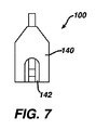
図6、7及び8を参照すると、所望により、分析試験ストリップ100は、利用者用持ち手として専ら構成された少なくとも1つの一体化支持シートを更に含みうる。図6〜8の実施形態では、分析試験ストリップ100は、第1一体化支持シート140及び第2一体化支持シート142を含む。更に、第1絶縁層の一部、第1導電層、パターン化スペーサ層、第2絶縁層、及び第2導電層は、第1一体化支持シート140と第2一体化支持シート142との間に配設される。第1一体化支持シート140は、第1導電層の電気接触パッド及びパターン化スペーサ層の電気接触パッドが露出されるように構成される。そのような露出は、使用中の試験計測器との電気接触を可能にする。
With reference to FIGS. 6, 7 and 8, if desired, the
第1及び第2の一体化支持シートは、例えば、紙、厚紙、又はプラスチック材料が含まれる任意の適した材料で形成することができる。第1及び第2の一体化支持シートは、本実施形態において専ら利用者用持ち手として構成されるので、比較的安価な材料で形成することができる。そのような一体化支持シートは、例えば、さもなければ比較的小さくなりかつ取り扱いが困難になりうる分析試験ストリップの取り扱いを容易にするものであることにおいて、有益である。 The first and second integrated support sheets can be formed of any suitable material including, for example, paper, cardboard, or plastic material. Since the first and second integrated support sheets are configured exclusively as a handle for a user in the present embodiment, they can be formed of a relatively inexpensive material. Such an integrated support sheet is beneficial, for example, in facilitating handling of analytical test strips that would otherwise be relatively small and difficult to handle.
図10は、体液試料(例えば、全血試料)中の検体(例えばグルコース)の判定のための方法1000における段階を図示する流れ図である。方法1000は、第1導電層の第1電極部及び第3導電層の第2電極部を内部に有する分析試験ストリップの試料受容チャンバ内に体液試料を導入する工程を含む(図10の工程1010を参照)。加えて、第1電極部と第2電極部は対向関係にある。
FIG. 10 is a flow diagram illustrating steps in a
方法1000の工程1020で、分析試験ストリップの、第1導電層の電気接触パッドを介して、及びパターン化スペーサ層の第2導電層の電気接触パッドを介して、第1電極部及び第2電極部の電気応答が測定される。パターン化スペーサ層は、第1導電層と第3導電層との間に配設される。更に、第1導電層の電気接触パッド及び第2導電層は、一方向に積層された関係で構成され、第2電極部は、第2導電層の電気接触パッドと電気通信する。
At
方法1000は、測定された電気応答に基づいて検体を判定する工程1030もまた含む。
本発明の実施形態による、本明細書に記載された分析試験ストリップの技術、利益、及び特徴のいずれをも取り入れるように方法1000が容易に改変されうることは、本開示の知見を得れば当業者によって認識されるところであろう。
Given the knowledge of this disclosure, the
一般には、本発明の実施形態による試験計測器と共に用いるための不活性の支持基材を有する分析試験ストリップは、分析試験ストリップモジュールと、電気化学的かつ電気的に不活性の支持基材(不活性の支持基材とも呼ばれる)とを含む。分析試験ストリップモジュールは、第1電極部と、第1電極部と対向関係にある第2電極部と、積層型一方向構成の第1及び第2の電気接触パッドとを有する。電気化学的かつ電気的に不活性の支持基材は、上面及び外縁を有する。更に、分析試験ストリップモジュールは、第1の電気接触パッド及び第2の電気接触パッドが電気化学的かつ電気的に不活性の支持基材の外縁を超えて延在するように、かつ電気化学的かつ電気的に不活性の支持基材が分析試験ストリップモジュールを超えて延在するように、電気化学的かつ電気的に不活性の支持基材の上面に取り付けられる。 In general, an analytical test strip having an inert support substrate for use with a test instrument according to an embodiment of the present invention comprises an analytical test strip module and an electrochemically and electrically inert support substrate (inactive Active support substrate). The analytical test strip module includes a first electrode portion, a second electrode portion facing the first electrode portion, and first and second electrical contact pads having a stacked unidirectional configuration. The electrochemically and electrically inert support substrate has a top surface and an outer edge. In addition, the analytical test strip module may be configured such that the first electrical contact pad and the second electrical contact pad extend beyond the outer edge of the electrochemically and electrically inert support substrate, and electrochemically. And is attached to the top surface of the electrochemically and electrically inert support substrate such that the electrically inert support substrate extends beyond the analytical test strip module.
図11〜14を参照して説明し、かつそれらで図示したように、「分析試験ストリップモジュール」という用語は、本発明の多様な実施形態による不活性の支持基材を有する分析試験ストリップを生産するために不活性の支持基材に取り付けられるモジュールを指す。本開示の知見を得た当業者は、そのような分析試験ストリップモジュールが、本明細書の他の箇所に記載される本発明の実施形態による不活性の支持基材を有さない分析試験ストリップと同等物であることを認識するであろう。この同等性は、図11、12、13及び14の要素識別番号に反映される。 As described with reference to FIGS. 11-14 and illustrated therein, the term “analytical test strip module” produces an analytical test strip having an inert support substrate in accordance with various embodiments of the present invention. Refers to a module that is attached to an inert support substrate. Those skilled in the art having the knowledge of the present disclosure will recognize that such an analytical test strip module does not have an inert support substrate according to embodiments of the present invention as described elsewhere herein. You will recognize that it is equivalent. This equivalence is reflected in the element identification numbers in FIGS.
不活性の支持基材に適用される「不活性」という用語は、導電性でなく、かつ、不活性の支持基材の上面に取り付けられる分析試験ストリップモジュールの電気化学的かつ電気的機能に電気的又は電気化学的に影響しない若しくは関与しない支持基材を指す。そのような不活性の支持基材は、本明細書では、「電気化学的かつ電気的に不活性の支持体」とも呼ばれる。 The term “inert” as applied to an inert support substrate refers to the electrochemical and electrical function of an analytical test strip module that is not conductive and is attached to the top surface of the inert support substrate. It refers to a supporting substrate that does not affect or participate in the target or electrochemically. Such inert support substrates are also referred to herein as “electrochemically and electrically inert supports”.
本発明の実施形態による不活性の支持基材を有する分析試験ストリップは、分析試験ストリップを利用者が手作業で取り扱うのを不活性の支持基材が助け、かつ不活性の支持体とともに分析試験ストリップを試験計測器に挿入するのを導くものであることにおいて、特に有益である。加えて、分析試験ストリップモジュールは、体液試料が分析試験ストリップモジュールの長手方向側面(即ち側面)に適用されるが、不活性の支持基材の端部(即ち、より小さい縁)には適用されないように、不活性の支持基材に取り付けることができる(具体的には、図11及び12を参照)。これに関して、不活性の支持基材から独立して考慮すると、分析試験ストリップモジュールのこのサイドフィル(side-fill)構成は、不活性の支持体を有する分析試験ストリップのエンドフィル(end-fill)構成となる。不活性の支持体を有する分析試験ストリップのそのようなエンドフィル構成は、一部の利用者によってよりユーザーフレンドリーであると知覚されうる。 An analytical test strip having an inert support substrate according to an embodiment of the present invention is an analytical test strip with an inert support that helps the user to manually handle the analytical test strip and with the inert support. It is particularly beneficial in guiding the insertion of the strip into the test instrument. In addition, the analytical test strip module is not applied to the end (ie, smaller edge) of the inert support substrate, although the body fluid sample is applied to the longitudinal side (ie, side) of the analytical test strip module. Can be attached to an inert support substrate (see specifically FIGS. 11 and 12). In this regard, when considered independent of the inert support substrate, this side-fill configuration of the analytical test strip module is the end-fill of the analytical test strip with an inert support. It becomes composition. Such an endfill configuration of an analytical test strip having an inert support can be perceived as more user friendly by some users.
本発明の実施形態による不活性の支持基材を有する分析試験ストリップは、分析試験ストリップモジュールと不活性の支持基材との間の電気接続がないこと、かつ分析試験ストリップモジュールと不活性の支持基材との間の正確な整合の必要がなく、それゆえ容易かつ安価に製造できることにおいてもまた、有益である。 An analytical test strip having an inert support substrate according to an embodiment of the present invention has no electrical connection between the analytical test strip module and the inert support substrate, and the analytical test strip module and the inert support. It is also beneficial in that there is no need for precise alignment with the substrate and therefore it can be manufactured easily and inexpensively.
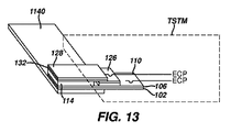
図11は、本発明の実施形態による不活性の支持基材1100を有する分析試験ストリップの簡略分解斜視図である。図12は、図11の不活性の支持基材を有する分析試験ストリップの簡略斜視図である。図13は、試験計測器(TSTM、点線で輪郭のみが描かれる)に挿入され、かつ試験計測器の電気コネクタピン(ECP)と接触している、図11の不活性の支持基材を有する分析試験ストリップの遠位部の簡略図である。図14は、図13にも図示される試験計測器に挿入された不活性の支持基材を有する分析試験ストリップの遠位部の簡略平面図である。
FIG. 11 is a simplified exploded perspective view of an analytical test strip having an
図11〜14を参照すると、試験計測器とともに使用する不活性の支持基材を有する分析試験ストリップ1100は、第1電極部108及び、第1電極部108と対向関係にある第2電極部134を有する分析試験ストリップモジュール1120を含む。分析試験ストリップモジュール1120は、少なくとも第1電気接触パッド110及び第2電気接触パッド126をも含み、第1及び第2の電気接触パッド(それぞれ、110及び126)は、積層型一方向構成で構成される。分析試験ストリップモジュール1120の要素の残りは、図1〜6に関して説明済みであり、図中、同様の要素識別番号は、同様の要素を示す。
Referring to FIGS. 11-14, an
不活性の支持基材1100を有する分析試験ストリップは、上面1160及び外縁1180を有する電気化学的かつ電気的に不活性の支持基材1140もまた含む(具体的には、図12を参照)。
The analytical test strip having an
分析試験ストリップモジュール1120は、第1電気接触パッド110及び第2電気接触パッド126が電気化学的かつ電気的に不活性の支持基材1140の外縁1180を超えて延在するように、上面1160に取り付けられる。更に、この取り付け構成では、電気化学的かつ電気的に不活性の支持基材1140が分析試験ストリップモジュール1120を超えて延在し、それにより、上面1160の一部が露出されたままになる(例えば図12を参照)。
Analytical test strip module 1120 is formed on
具体的には、図12、13及び14を参照すると、第1電気接触パッド及び第2電気接触パッドの延在部分は、第1電気接触パッド及び第2電気接触パッドを試験計測器に動作可能に挿入するために構成される。更に、図11〜14の実施形態では、(分析試験ストリップモジュールの縁上の)試料受容チャンバが不活性の支持基材の端部上にあるように、分析試験ストリップモジュールが不活性の支持基材のより小さい縁に沿って長手方向に取り付けられていることに留意されたい。 Specifically, referring to FIGS. 12, 13, and 14, the extended portions of the first and second electrical contact pads can operate the first and second electrical contact pads on the test instrument. Configured to insert into. Further, in the embodiment of FIGS. 11-14, the analytical test strip module is on an inert support group such that the sample receiving chamber (on the edge of the analytical test strip module) is on the end of an inert support substrate. Note that it is attached longitudinally along the smaller edges of the material.
分析試験ストリップモジュール1120は、例えば、接着及びラミネーション技法が含まれる任意の適した技法を用いて不活性の支持基材に取り付けることができる。 Analytical test strip module 1120 can be attached to an inert support substrate using any suitable technique including, for example, adhesion and lamination techniques.
電気化学的かつ電気的に不活性の支持基材1140は、例えば、プラスチック材料(例えば、200μm〜500μmの範囲の厚さを有する、Dupont Melinexの材料(DuPont Corporation)が含まれる、ポリエチレン材料)が含まれる任意の適した材料で形成することができる。不活性の支持基材を形成するために使用する材料の剛性は、使用中の不活性の支持基材の動作上の変形が最小限であるように、十分でなくてはならない。電気化学的かつ電気的に不活性の支持基材は、不活性の支持体を有する分析試験ストリップが試験計測器(TSTM)に挿入され、第1及び第2の電気接触パッドと試験計測器のECPとの間に接触が生じたときに、実質的に座屈又は屈曲してはならない(例えば、図13及び14を参照)。
The electrochemically and electrically
分析試験ストリップモジュール1120及び電気化学的かつ電気的に不活性の支持基材1140は、任意の適した寸法であってよい。分析試験ストリップの代表的な、しかし限定的ではない寸法は、2.0mm〜3.5mmの範囲の幅、約10.0mmの長さである。電気化学的かつ電気的に不活性の支持基材1140は、例えば、8.0mmの幅、35.0mmの長さ、200μm〜500μmの範囲の厚さを有しうる。これらの代表的な寸法では、(分析試験ストリップモジュールの長さが、不活性の支持基材の幅にわたって取り付けられるので)分析試験ストリップモジュール1120の第1及び第2の接触パッドは、電気化学的かつ電気的に不活性の支持基材の縁を2.00mm超えて延在することになり、電気化学的かつ電気的に不活性の支持基材は、分析試験ストリップモジュールを少なくとも31.5mm〜33.0mm超えて延在することになる。具体的には、両方の延在部分が図示されている図12を参照されたい。
The analytical test strip module 1120 and the electrochemically and electrically
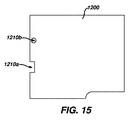
図15は、本発明の実施形態に採用しうる別の電気化学的かつ電気的に不活性の支持基材1200の簡略平面図である。電気化学的かつ電気的に不活性の支持基材1200は、分析試験ストリップ及び電気化学的かつ電気的に不活性の支持基材を試験計測器に挿入するのを助けるように構成された機械物理的整合機構1210a(即ちノッチ)並びに1210b(即ち不活性の支持基材を貫通している円形開口部)を含む。そのような機械物理的整合機構は、分析試験ストリップ及び電気化学的かつ電気的に不活性の支持基材が正しく配向されて試験計測器に挿入されたときのみに、試験計測器の対応する機構と合体するように構成される。所望により、電気化学的かつ電気的に不活性の支持基材の表面は、例えば、バーコード、ロゴ、及び/又は較正情報を指定するしるしなどの情報提供マーキングを含みうる。不活性の支持基材上にそのような情報提供マーキングを提供することは、様々な最適化された柔軟なサプライチェーン管理計画を可能にする。例えば、適切な較正コード情報をそれ自体に有する不活性の支持基材を、こうした分析試験ストリップモジュールのバッチの較正後に、分析試験ストリップモジュールと組み合わせることができる。加えて、出荷の直前に、不活性の支持基材にセキュリティ情報提供マーキングを適用することができる。
FIG. 15 is a simplified plan view of another electrochemically and electrically
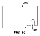
図16は、本発明の実施形態に採用しうるまた別の電気化学的かつ電気的に不活性の支持基材1300の簡略平面図である。電気化学的かつ電気的に不活性の支持基材1300は、付随する分析試験ストリップモジュールの試料受容チャンバ(明確性を期すために図16には図示されていない)と整合される試料キャビティ回避ノッチ1320を含む。試料キャビティ回避ノッチ1320の配置は、体液試料適用部の付近で電気化学的かつ電気的に不活性の支持基材と分析試験ストリップモジュールとの間にキャビティが作られることを防止する。そのようなキャビティが存在すると、体液試料が試料受容チャンバではなくキャビティに不要に流れ込む場合がある。
FIG. 16 is a simplified plan view of yet another electrochemically and electrically
図17は、体液試料(例えば、全血試料)中の検体(例えばグルコース)の判定のための方法1400における段階を図示する流れ図である。方法1400は、第1導電層の第1電極部及び第3導電層の第2電極部をそれ自体に有する不活性の支持基材を有する分析試験ストリップの分析試験ストリップモジュールの試料受容チャンバ内に体液試料を導入する工程を含む(図17の工程1410を参照)。加えて、第1電極部と第2電極部は対向関係にある。
FIG. 17 is a flow diagram illustrating steps in a
方法1400の工程1420で、分析試験ストリップモジュールの第1導電層の第1電気接触パッドを介して、及び第2導電層の第2電気接触パッドを介して、第1電極部及び第2電極部の電気応答が測定される。更に、第1導電層の第1電気接触パッド及び第2導電層の第2電気接触パッドは、一方向に積層された関係で構成され、第2の電極部は、第2の導電層の第2の電気接触パッドと電気通信し、不活性の支持体は、分析試験ストリップモジュールを超えて延在する。
In
方法1400は、測定された電気応答に基づいて検体を判定する工程1430もまた含む。
The
本発明の実施形態に基づき、かつ本明細書に記載される不活性の支持基材を有する分析試験ストリップの技術、利益、及び特徴のいずれをも取り入れるように方法1400が容易に改変されうることは、本開示の知見を得れば当業者によって認識されるところであろう。
以上、本発明の好ましい実施形態を図示、説明したが、こうした実施形態は、あくまで一例として与えられたものであることは当業者には明らかであろう。当業者であれば、本発明から逸脱することなく、多くの変形、変更、及び置換が想到されるであろう。本発明を実施するうえで本明細書で述べた実施形態には、様々な代替例が用いられ得る点は理解されるべきである。以下の「特許請求の範囲」は、本発明の範囲を定義するとともに特許請求の範囲に含まれる装置及び方法、並びにそれらの均等物をこれによって網羅することを目的としたものである。 While preferred embodiments of the present invention have been illustrated and described above, it will be apparent to those skilled in the art that such embodiments are given by way of example only. Many variations, modifications, and substitutions will occur to those skilled in the art without departing from the invention. It should be understood that various alternatives may be used in the embodiments described herein in practicing the present invention. The following “claims” are intended to define the scope of the present invention and thereby cover the apparatus and methods included in the claims, and their equivalents.
〔実施の態様〕
(1) 試験計測器と共に用いるための不活性の支持基材(inert carrier substrate)を有する分析試験ストリップであって、
分析試験ストリップモジュールであって、
第1電極部、
前記第1電極部と対向関係にある第2電極部、並びに
少なくとも第1電気接触パッド及び第2電気接触パッドであって、積層型一方向構成で構成される、第1電気接触パッド及び第2電気接触パッドを備える、分析試験ストリップモジュールと、
電気化学的かつ電気的に不活性の支持基材であって、
上面、及び
外縁を有する、電気化学的かつ電気的に不活性の支持基材と、を備え、
前記分析試験ストリップモジュールが、前記第1電気接触パッド及び前記第2電気接触パッドが前記電気化学的かつ電気的に不活性の支持基材の前記外縁を超えて延在するように、前記電気化学的かつ電気的に不活性の支持基材の前記上面に取り付けられ、かつ、
前記電気化学的かつ電気的に不活性の支持基材が、前記分析試験ストリップモジュールを超えて延在する、不活性の支持基材を有する分析試験ストリップ。
(2) 前記分析試験ストリップモジュールが、
第1絶縁層上面を有する第1絶縁層と、
前記第1絶縁層上面に配設された第1導電層であって、
前記第1電極部を含み、前記第1電気接触パッドが前記第1電極部と電気通信する、第1導電層と、
前記第1導電層の上に配設されたパターン化スペーサ層であって、
前記第1電極部の上に重なる体液試料受容チャンバを内部に画定する遠位部、並びに
上面及び前記上面に配設された第2導電層を有する絶縁性近位部を含み、前記第2導電層が、
層間接触部、及び
前記第2電気接触パッドを含む、パターン化スペーサ層と、
前記パターン化スペーサ層の上に配設され、第2絶縁層下面を有する第2絶縁層と、
前記第3絶縁層下面に配設された第3導電層であって、
前記第2電極部、及び
前記層間接触部の上に重なる近位部を含む、第3導電層と、を更に含み、
前記第2電極部が、前記試料受容チャンバの上に重なって配設され、かつ前記試料受容チャンバに対して露出され、かつ前記第1電極部と対向関係であり、
前記第3導電層の前記近位部が、前記分析試験ストリップの使用中に、前記第3導電層の前記第2電極部と前記パターン化スペーサ層の前記電気接触パッドとの間に電気接続が存在するように、前記第2導電層の前記層間接触部と動作可能に並置される、実施態様1に記載の不活性の支持基材を有する分析試験ストリップ。
(3) 前記不活性の支持基材が、少なくとも1つの機械物理的整合機構を含む、実施態様1に記載の不活性の支持基材を有する分析試験ストリップ。
(4) 前記不活性の支持基材が、少なくとも1つの試料キャビティ回避ノッチを含む、実施態様1に記載の不活性の支持基材を有する分析試験ストリップ。
(5) 前記不活性の支持基材が、情報提供マーキングを含む、実施態様1に記載の不活性の支持基材を有する分析試験ストリップ。
Embodiment
(1) An analytical test strip having an inert carrier substrate for use with a test instrument,
An analytical test strip module,
A first electrode part,
A second electrode portion facing the first electrode portion, and at least a first electric contact pad and a second electric contact pad, wherein the first electric contact pad and the second electric contact pad are configured in a stacked unidirectional configuration. An analytical test strip module comprising an electrical contact pad;
An electrochemically and electrically inert support substrate,
An electrochemically and electrically inert support substrate having an upper surface and an outer edge;
The analytical test strip module is configured to allow the first and second electrical contact pads to extend beyond the outer edge of the electrochemically and electrically inert support substrate. Attached to said top surface of a support substrate which is electrically and electrically inert, and
An analytical test strip having an inert support substrate, wherein the electrochemically and electrically inert support substrate extends beyond the analytical test strip module.
(2) The analytical test strip module is
A first insulating layer having an upper surface of the first insulating layer;
A first conductive layer disposed on an upper surface of the first insulating layer,
A first conductive layer including the first electrode portion, wherein the first electrical contact pad is in electrical communication with the first electrode portion;
A patterned spacer layer disposed on the first conductive layer,
A distal portion defining a bodily fluid sample receiving chamber overlying the first electrode portion; and an insulating proximal portion having an upper surface and a second conductive layer disposed on the upper surface; Layer
An interlayer contact portion, and a patterned spacer layer including the second electrical contact pad;
A second insulating layer disposed on the patterned spacer layer and having a lower surface of the second insulating layer;
A third conductive layer disposed on the lower surface of the third insulating layer,
A third conductive layer including a second portion overlying the second electrode portion and the interlayer contact portion;
The second electrode portion is disposed overlying the sample receiving chamber and exposed to the sample receiving chamber, and is in a facing relationship with the first electrode portion;
The proximal portion of the third conductive layer has an electrical connection between the second electrode portion of the third conductive layer and the electrical contact pad of the patterned spacer layer during use of the analytical test strip. 2. An analytical test strip having an inert support substrate according to embodiment 1 operatively juxtaposed with the interlayer contact of the second conductive layer, as present.
(3) The analytical test strip having an inert support substrate according to embodiment 1, wherein the inert support substrate comprises at least one mechanical-physical alignment mechanism.
4. The analytical test strip having an inert support substrate according to embodiment 1, wherein the inert support substrate includes at least one sample cavity avoidance notch.
5. The analytical test strip having an inert support substrate according to embodiment 1, wherein the inert support substrate comprises an informational marking.
(6) 前記分析試験ストリップモジュールが、電気化学に基づく分析試験ストリップモジュールである、実施態様1に記載の不活性の支持体を有する分析試験ストリップ。
(7) 前記電気化学に基づく分析試験ストリップモジュールが、体液試料中の検体の判定のために構成される、実施態様6に記載の不活性の支持基材を有する分析試験ストリップ。
(8) 前記検体がグルコースである、実施態様7に記載の不活性の支持基材を有する分析試験ストリップ。
(9) 前記第1電気接触パッド及び前記第2電気接触パッドの延在部分(extension)が、試験計測器への前記第1電気接触パッド及び前記第2電気接触パッドの動作可能な挿入のために構成される、実施態様1に記載の不活性の支持基材を有する分析試験ストリップ。
(10) 前記分析試験ストリップモジュールが、前記不活性の支持基材のより小さい縁に沿って縦方向に取り付けられる、実施態様1に記載の分析試験ストリップ及び不活性の支持体。
6. The analytical test strip having an inert support according to embodiment 1, wherein the analytical test strip module is an electrochemical-based analytical test strip module.
7. The analytical test strip having an inert support substrate according to embodiment 6, wherein the electrochemical-based analytical test strip module is configured for determination of an analyte in a body fluid sample.
(8) The analytical test strip having an inert support substrate according to embodiment 7, wherein the analyte is glucose.
(9) Extensions of the first electrical contact pad and the second electrical contact pad are for operable insertion of the first electrical contact pad and the second electrical contact pad into a test instrument. 2. An analytical test strip having an inert support substrate according to embodiment 1 configured in
10. The analytical test strip and inert support of embodiment 1, wherein the analytical test strip module is mounted longitudinally along a smaller edge of the inert support substrate.
(11) 体液試料中の検体を判定するための方法であって、
不活性の支持基材を有する分析試験ストリップの分析試験ストリップモジュールの試料受容チャンバに体液試料を導入する工程であって、前記試料受容チャンバが、第1導電層の第1電極部及び第3導電層の第2電極部を前記試料受容チャンバ内に有し、前記第1電極部及び前記第2電極部が対向関係であり、前記不活性の支持基材が前記分析試験ストリップモジュールを超えて延在する、工程、
前記第1導電層の第1電気接触パッドを介して、かつ前記分析試験ストリップモジュールの第2導電層の第2電気接触パッドを介して、前記第1電極部及び前記第2電極部の電気応答を測定する工程であって、
前記第1導電層の前記第1電気接触パッド及び前記第2導電層の前記第2電気接触パッドが、一方向に積層された関係で構成され、かつ前記不活性の支持基材の縁を超えて延在し、かつ
前記第2電極部が、前記第2導電層の前記電気接触パッドと電気通信する、工程、並びに、
その測定された電気応答に基づき、前記検体を判定する工程、を含む、方法。
(12) 前記分析試験ストリップが、電気化学に基づく分析試験ストリップである、実施態様11に記載の方法。
(13) 前記検体がグルコースである、実施態様12に記載の方法。
(14) 前記体液試料が全血試料である、実施態様12に記載の方法。
(15) 前記電気化学に基づく分析試験ストリップが、体液試料中の検体の判定のために構成される、実施態様12に記載の方法。
(11) A method for determining a specimen in a body fluid sample,
Introducing a body fluid sample into a sample receiving chamber of an analytical test strip module of an analytical test strip having an inert support substrate, wherein the sample receiving chamber comprises a first electrode portion of a first conductive layer and a third conductive layer; A second electrode portion of a layer in the sample receiving chamber, wherein the first electrode portion and the second electrode portion are in opposing relationship, and the inert support substrate extends beyond the analytical test strip module. Existing process,
Electrical response of the first electrode portion and the second electrode portion through the first electrical contact pad of the first conductive layer and through the second electrical contact pad of the second conductive layer of the analytical test strip module. A process of measuring
The first electrical contact pad of the first conductive layer and the second electrical contact pad of the second conductive layer are configured to be laminated in one direction and extend beyond the edge of the inert support substrate. And the second electrode portion is in electrical communication with the electrical contact pad of the second conductive layer, and
Determining the analyte based on the measured electrical response.
12. The method of embodiment 11, wherein the analytical test strip is an electrochemical based analytical test strip.
(13) The method according to embodiment 12, wherein the analyte is glucose.
(14) The method according to embodiment 12, wherein the body fluid sample is a whole blood sample.
15. The method of embodiment 12, wherein the electrochemical-based analytical test strip is configured for determination of an analyte in a body fluid sample.
(16) 前記測定する工程が、試験計測器を採用し、前記測定する工程が、前記不活性の支持基材の前記縁を越えて延在する前記第1電気接触パッド及び前記第2電気接触パッドを前記試験計測器に挿入することを含む、実施態様11に記載の方法。
(17) 前記不活性の支持基材が、前記挿入を助ける少なくとも1つの機械的整合機構を含む、実施態様16に記載の方法。
(18) 不活性の支持基材が情報提供マーキングを含む、実施態様11に記載の方法。
(19) 前記不活性の支持基材が、試料キャビティ回避ノッチを含む、実施態様11に記載の方法。
(20) 前記第1電気接触パッド及び前記第2電気接触パッドの延在部分が、前記測定する工程中の試験計測器への前記第1電気接触パッド及び前記第2電気接触パッドの動作可能な挿入のために構成される、実施態様11に記載の方法。
(16) The measuring step employs a test instrument, and the measuring step includes the first electrical contact pad and the second electrical contact extending beyond the edge of the inert support substrate. Embodiment 12. The method of embodiment 11 comprising inserting a pad into the test meter.
17. The method of embodiment 16, wherein the inert support substrate includes at least one mechanical alignment mechanism that assists in the insertion.
18. The method of embodiment 11 wherein the inert support substrate includes informational marking.
19. The method of embodiment 11, wherein the inert support substrate includes a sample cavity avoidance notch.
(20) Extension portions of the first electrical contact pad and the second electrical contact pad are operable for the first electrical contact pad and the second electrical contact pad to the test meter during the measuring process. Embodiment 12. The method of embodiment 11 configured for insertion.
Claims (20)
分析試験ストリップモジュールであって、
第1電極部、
前記第1電極部と対向関係にある第2電極部、並びに
少なくとも第1電気接触パッド及び第2電気接触パッドであって、積層型一方向構成で構成される、第1電気接触パッド及び第2電気接触パッドを備える、分析試験ストリップモジュールと、
電気化学的かつ電気的に不活性の支持基材であって、
上面、及び
外縁を有する、電気化学的かつ電気的に不活性の支持基材と、を備え、
前記分析試験ストリップモジュールが、前記第1電気接触パッド及び前記第2電気接触パッドが前記電気化学的かつ電気的に不活性の支持基材の前記外縁を超えて延在するように、前記電気化学的かつ電気的に不活性の支持基材の前記上面に取り付けられ、かつ、
前記電気化学的かつ電気的に不活性の支持基材が、前記分析試験ストリップモジュールを超えて延在する、不活性の支持基材を有する分析試験ストリップ。 An analytical test strip having an inert support substrate for use with a test instrument,
An analytical test strip module,
A first electrode part,
A second electrode portion facing the first electrode portion, and at least a first electric contact pad and a second electric contact pad, wherein the first electric contact pad and the second electric contact pad are configured in a stacked unidirectional configuration. An analytical test strip module comprising an electrical contact pad;
An electrochemically and electrically inert support substrate,
An electrochemically and electrically inert support substrate having an upper surface and an outer edge;
The analytical test strip module is configured to allow the first and second electrical contact pads to extend beyond the outer edge of the electrochemically and electrically inert support substrate. Attached to said top surface of a support substrate which is electrically and electrically inert, and
An analytical test strip having an inert support substrate, wherein the electrochemically and electrically inert support substrate extends beyond the analytical test strip module.
第1絶縁層上面を有する第1絶縁層と、
前記第1絶縁層上面に配設された第1導電層であって、
前記第1電極部を含み、前記第1電気接触パッドが前記第1電極部と電気通信する、第1導電層と、
前記第1導電層の上に配設されたパターン化スペーサ層であって、
前記第1電極部の上に重なる体液試料受容チャンバを内部に画定する遠位部、並びに
上面及び前記上面に配設された第2導電層を有する絶縁性近位部を含み、前記第2導電層が、
層間接触部、及び
前記第2電気接触パッドを含む、パターン化スペーサ層と、
前記パターン化スペーサ層の上に配設され、第2絶縁層下面を有する第2絶縁層と、
前記第3絶縁層下面に配設された第3導電層であって、
前記第2電極部、及び
前記層間接触部の上に重なる近位部を含む、第3導電層と、を更に含み、
前記第2電極部が、前記試料受容チャンバの上に重なって配設され、かつ前記試料受容チャンバに対して露出され、かつ前記第1電極部と対向関係であり、
前記第3導電層の前記近位部が、前記分析試験ストリップの使用中に、前記第3導電層の前記第2電極部と前記パターン化スペーサ層の前記電気接触パッドとの間に電気接続が存在するように、前記第2導電層の前記層間接触部と動作可能に並置される、請求項1に記載の不活性の支持基材を有する分析試験ストリップ。 The analytical test strip module is
A first insulating layer having an upper surface of the first insulating layer;
A first conductive layer disposed on an upper surface of the first insulating layer,
A first conductive layer including the first electrode portion, wherein the first electrical contact pad is in electrical communication with the first electrode portion;
A patterned spacer layer disposed on the first conductive layer,
A distal portion defining a bodily fluid sample receiving chamber overlying the first electrode portion; and an insulating proximal portion having an upper surface and a second conductive layer disposed on the upper surface; Layer
An interlayer contact portion, and a patterned spacer layer including the second electrical contact pad;
A second insulating layer disposed on the patterned spacer layer and having a lower surface of the second insulating layer;
A third conductive layer disposed on the lower surface of the third insulating layer,
A third conductive layer including a second portion overlying the second electrode portion and the interlayer contact portion;
The second electrode portion is disposed overlying the sample receiving chamber and exposed to the sample receiving chamber, and is in a facing relationship with the first electrode portion;
The proximal portion of the third conductive layer has an electrical connection between the second electrode portion of the third conductive layer and the electrical contact pad of the patterned spacer layer during use of the analytical test strip. The analytical test strip having an inert support substrate according to claim 1 operatively juxtaposed with the interlayer contact of the second conductive layer, as it exists.
不活性の支持基材を有する分析試験ストリップの分析試験ストリップモジュールの試料受容チャンバに体液試料を導入する工程であって、前記試料受容チャンバが、第1導電層の第1電極部及び第3導電層の第2電極部を前記試料受容チャンバ内に有し、前記第1電極部及び前記第2電極部が対向関係であり、前記不活性の支持基材が前記分析試験ストリップモジュールを超えて延在する、工程、
前記第1導電層の第1電気接触パッドを介して、かつ前記分析試験ストリップモジュールの第2導電層の第2電気接触パッドを介して、前記第1電極部及び前記第2電極部の電気応答を測定する工程であって、
前記第1導電層の前記第1電気接触パッド及び前記第2導電層の前記第2電気接触パッドが、一方向に積層された関係で構成され、かつ前記不活性の支持基材の縁を超えて延在し、かつ
前記第2電極部が、前記第2導電層の前記電気接触パッドと電気通信する、工程、並びに、
その測定された電気応答に基づき、前記検体を判定する工程、を含む、方法。 A method for determining a specimen in a body fluid sample,
Introducing a body fluid sample into a sample receiving chamber of an analytical test strip module of an analytical test strip having an inert support substrate, wherein the sample receiving chamber comprises a first electrode portion of a first conductive layer and a third conductive layer; A second electrode portion of a layer in the sample receiving chamber, wherein the first electrode portion and the second electrode portion are in opposing relationship, and the inert support substrate extends beyond the analytical test strip module. Existing process,
Electrical response of the first electrode portion and the second electrode portion through the first electrical contact pad of the first conductive layer and through the second electrical contact pad of the second conductive layer of the analytical test strip module. A process of measuring
The first electrical contact pad of the first conductive layer and the second electrical contact pad of the second conductive layer are configured to be laminated in one direction and extend beyond the edge of the inert support substrate. And the second electrode portion is in electrical communication with the electrical contact pad of the second conductive layer, and
Determining the analyte based on the measured electrical response.
Applications Claiming Priority (5)
| Application Number | Priority Date | Filing Date | Title |
|---|---|---|---|
| US13/410,609 US9217723B2 (en) | 2012-03-02 | 2012-03-02 | Co-facial analytical test strip with stacked unidirectional contact pads |
| US13/410,609 | 2012-03-02 | ||
| US13/585,330 US20130228475A1 (en) | 2012-03-02 | 2012-08-14 | Co-facial analytical test strip with stacked unidirectional contact pads and inert carrier substrate |
| US13/585,330 | 2012-08-14 | ||
| PCT/EP2013/054222 WO2013128026A1 (en) | 2012-03-02 | 2013-03-01 | Test strip with stacked unidirectional contact pads and inert carrier substrate |
Publications (1)
| Publication Number | Publication Date |
|---|---|
| JP2015508901A true JP2015508901A (en) | 2015-03-23 |
Family
ID=47780070
Family Applications (1)
| Application Number | Title | Priority Date | Filing Date |
|---|---|---|---|
| JP2014559257A Pending JP2015508901A (en) | 2012-03-02 | 2013-03-01 | Coplanar analysis test strip with laminated unidirectional contact pads and inert support substrate |
Country Status (11)
| Country | Link |
|---|---|
| US (1) | US20130228475A1 (en) |
| EP (1) | EP2839020A1 (en) |
| JP (1) | JP2015508901A (en) |
| KR (1) | KR20140137409A (en) |
| CN (1) | CN104160036A (en) |
| AU (1) | AU2013224847B2 (en) |
| CA (1) | CA2865459A1 (en) |
| IN (1) | IN2014DN07234A (en) |
| RU (1) | RU2014139828A (en) |
| TW (2) | TWI583948B (en) |
| WO (1) | WO2013128026A1 (en) |
Families Citing this family (5)
| Publication number | Priority date | Publication date | Assignee | Title |
|---|---|---|---|---|
| CN102954989A (en) * | 2012-11-30 | 2013-03-06 | 北京宏元兴邦科技有限责任公司 | Electrochemical sensing strip |
| US20160091450A1 (en) * | 2014-09-25 | 2016-03-31 | Lifescan Scotland Limited | Accurate analyte measurements for electrochemical test strip to determine analyte measurement time based on measured temperature, physical characteristic and estimated analyte value and their temperature compensated values |
| EP3234565A1 (en) * | 2014-12-19 | 2017-10-25 | Roche Diagnostics GmbH | Test element for electrochemically detecting at least one analyte |
| TWI601954B (en) * | 2016-09-09 | 2017-10-11 | 長庚大學 | Capacitor-based fluid sensing unit and the method of use |
| CN108469460B (en) * | 2018-03-09 | 2019-03-29 | 深圳市刷新智能电子有限公司 | Perspiration sensor and preparation method thereof |
Family Cites Families (8)
| Publication number | Priority date | Publication date | Assignee | Title |
|---|---|---|---|---|
| JP3528529B2 (en) * | 1997-07-31 | 2004-05-17 | Nok株式会社 | Biosensor |
| US6071391A (en) * | 1997-09-12 | 2000-06-06 | Nok Corporation | Enzyme electrode structure |
| CA2566358C (en) * | 2004-05-21 | 2016-12-20 | Agamatrix, Inc. | Electrochemical cell and method for making an electrochemical cell |
| US7545272B2 (en) * | 2005-02-08 | 2009-06-09 | Therasense, Inc. | RF tag on test strips, test strip vials and boxes |
| ATE433711T1 (en) * | 2005-12-19 | 2009-07-15 | Hoffmann La Roche | SANDWICH SENSOR FOR DETERMINING AN ANALYTE CONCENTRATION |
| AU2008279043A1 (en) * | 2007-07-26 | 2009-01-29 | Agamatrix, Inc. | Electrochemical test strips |
| US7922985B2 (en) * | 2008-06-24 | 2011-04-12 | Lifescan, Inc. | Analyte test strip for accepting diverse sample volumes |
| US8032321B2 (en) * | 2008-07-15 | 2011-10-04 | Bayer Healthcare Llc | Multi-layered biosensor encoding systems |
-
2012
- 2012-08-14 US US13/585,330 patent/US20130228475A1/en not_active Abandoned
-
2013
- 2013-03-01 EP EP13707170.0A patent/EP2839020A1/en not_active Withdrawn
- 2013-03-01 WO PCT/EP2013/054222 patent/WO2013128026A1/en active Application Filing
- 2013-03-01 TW TW102107192A patent/TWI583948B/en not_active IP Right Cessation
- 2013-03-01 JP JP2014559257A patent/JP2015508901A/en active Pending
- 2013-03-01 RU RU2014139828A patent/RU2014139828A/en not_active Application Discontinuation
- 2013-03-01 KR KR1020147027754A patent/KR20140137409A/en not_active Application Discontinuation
- 2013-03-01 AU AU2013224847A patent/AU2013224847B2/en not_active Ceased
- 2013-03-01 CN CN201380012191.7A patent/CN104160036A/en active Pending
- 2013-03-01 TW TW102107191A patent/TW201346256A/en unknown
- 2013-03-01 CA CA2865459A patent/CA2865459A1/en not_active Abandoned
- 2013-03-01 IN IN7234DEN2014 patent/IN2014DN07234A/en unknown
Also Published As
| Publication number | Publication date |
|---|---|
| AU2013224847A1 (en) | 2014-10-16 |
| EP2839020A1 (en) | 2015-02-25 |
| RU2014139828A (en) | 2016-04-20 |
| AU2013224847B2 (en) | 2018-11-15 |
| US20130228475A1 (en) | 2013-09-05 |
| CN104160036A (en) | 2014-11-19 |
| TW201346256A (en) | 2013-11-16 |
| KR20140137409A (en) | 2014-12-02 |
| TW201350842A (en) | 2013-12-16 |
| CA2865459A1 (en) | 2013-09-06 |
| TWI583948B (en) | 2017-05-21 |
| WO2013128026A1 (en) | 2013-09-06 |
| IN2014DN07234A (en) | 2015-04-24 |
Similar Documents
| Publication | Publication Date | Title |
|---|---|---|
| EP2317315B1 (en) | Dual chamber, multi-analyte test strip with opposing electrodes and body fluid test method using this strip | |
| US9217723B2 (en) | Co-facial analytical test strip with stacked unidirectional contact pads | |
| JP2011053211A (en) | Multi-analyte test strip with shared counter/reference electrode and inline electrode configuration | |
| US20110079522A1 (en) | Multi-analyte test strip with inline working electrodes and shared opposing counter/reference electrode | |
| US8632664B2 (en) | Test meter for use with a dual chamber, multi-analyte test strip with opposing electrodes | |
| US20150144507A1 (en) | Folded biosensor | |
| JP2015508901A (en) | Coplanar analysis test strip with laminated unidirectional contact pads and inert support substrate | |
| JP2011007788A (en) | Analyte test strip with combination electric contact and meter identification mechanism | |
| JP2016530515A (en) | Analytical test strip with cantilevered contacts | |
| KR20110046307A (en) | Test meter for use with a dual chamber, multi-analyte test strip with opposing electrodes | |
| KR20110046304A (en) | Dual chamber multi-analyte test strip with opposite electrode |