JP2015508697A - Extracorporeal blood circuit reservoir with angled venous inlet luer port - Google Patents
Extracorporeal blood circuit reservoir with angled venous inlet luer port Download PDFInfo
- Publication number
- JP2015508697A JP2015508697A JP2014559909A JP2014559909A JP2015508697A JP 2015508697 A JP2015508697 A JP 2015508697A JP 2014559909 A JP2014559909 A JP 2014559909A JP 2014559909 A JP2014559909 A JP 2014559909A JP 2015508697 A JP2015508697 A JP 2015508697A
- Authority
- JP
- Japan
- Prior art keywords
- venous
- connector body
- port
- blood
- inlet
- Prior art date
- Legal status (The legal status is an assumption and is not a legal conclusion. Google has not performed a legal analysis and makes no representation as to the accuracy of the status listed.)
- Granted
Links
Images


Classifications
-
- A—HUMAN NECESSITIES
- A61—MEDICAL OR VETERINARY SCIENCE; HYGIENE
- A61M—DEVICES FOR INTRODUCING MEDIA INTO, OR ONTO, THE BODY; DEVICES FOR TRANSDUCING BODY MEDIA OR FOR TAKING MEDIA FROM THE BODY; DEVICES FOR PRODUCING OR ENDING SLEEP OR STUPOR
- A61M1/00—Suction or pumping devices for medical purposes; Devices for carrying-off, for treatment of, or for carrying-over, body-liquids; Drainage systems
- A61M1/36—Other treatment of blood in a by-pass of the natural circulatory system, e.g. temperature adaptation, irradiation ; Extra-corporeal blood circuits
- A61M1/3621—Extra-corporeal blood circuits
- A61M1/367—Circuit parts not covered by the preceding subgroups of group A61M1/3621
-
- A—HUMAN NECESSITIES
- A61—MEDICAL OR VETERINARY SCIENCE; HYGIENE
- A61M—DEVICES FOR INTRODUCING MEDIA INTO, OR ONTO, THE BODY; DEVICES FOR TRANSDUCING BODY MEDIA OR FOR TAKING MEDIA FROM THE BODY; DEVICES FOR PRODUCING OR ENDING SLEEP OR STUPOR
- A61M1/00—Suction or pumping devices for medical purposes; Devices for carrying-off, for treatment of, or for carrying-over, body-liquids; Drainage systems
- A61M1/36—Other treatment of blood in a by-pass of the natural circulatory system, e.g. temperature adaptation, irradiation ; Extra-corporeal blood circuits
- A61M1/3621—Extra-corporeal blood circuits
- A61M1/3627—Degassing devices; Buffer reservoirs; Drip chambers; Blood filters
- A61M1/3632—Combined venous-cardiotomy reservoirs
-
- A—HUMAN NECESSITIES
- A61—MEDICAL OR VETERINARY SCIENCE; HYGIENE
- A61M—DEVICES FOR INTRODUCING MEDIA INTO, OR ONTO, THE BODY; DEVICES FOR TRANSDUCING BODY MEDIA OR FOR TAKING MEDIA FROM THE BODY; DEVICES FOR PRODUCING OR ENDING SLEEP OR STUPOR
- A61M1/00—Suction or pumping devices for medical purposes; Devices for carrying-off, for treatment of, or for carrying-over, body-liquids; Drainage systems
- A61M1/36—Other treatment of blood in a by-pass of the natural circulatory system, e.g. temperature adaptation, irradiation ; Extra-corporeal blood circuits
- A61M1/3621—Extra-corporeal blood circuits
- A61M1/3627—Degassing devices; Buffer reservoirs; Drip chambers; Blood filters
- A61M1/3633—Blood component filters, e.g. leukocyte filters
-
- B—PERFORMING OPERATIONS; TRANSPORTING
- B01—PHYSICAL OR CHEMICAL PROCESSES OR APPARATUS IN GENERAL
- B01D—SEPARATION
- B01D35/00—Filtering devices having features not specifically covered by groups B01D24/00 - B01D33/00, or for applications not specifically covered by groups B01D24/00 - B01D33/00; Auxiliary devices for filtration; Filter housing constructions
- B01D35/02—Filters adapted for location in special places, e.g. pipe-lines, pumps, stop-cocks
Landscapes
- Health & Medical Sciences (AREA)
- Heart & Thoracic Surgery (AREA)
- Vascular Medicine (AREA)
- Life Sciences & Earth Sciences (AREA)
- Engineering & Computer Science (AREA)
- Anesthesiology (AREA)
- Biomedical Technology (AREA)
- Hematology (AREA)
- Cardiology (AREA)
- Animal Behavior & Ethology (AREA)
- General Health & Medical Sciences (AREA)
- Public Health (AREA)
- Veterinary Medicine (AREA)
- Chemical & Material Sciences (AREA)
- Chemical Kinetics & Catalysis (AREA)
- External Artificial Organs (AREA)
Abstract
ハウジング、静脈入口サブアセンブリ、および静脈フィルターを含む体外リザーバデバイス。静脈サブアセンブリは、ハウジングに装着され、ダウンチューブおよびルアーポートコネクタ本体を含む。コネクタ本体はダウンチューブから延在して、ダウンチューブのルーメンに対して開放される通路を形成する。コネクタ本体は、通路からの流体流れが、90?未満の角度で、一次ルーメンに沿って、流体の流路と合流するように配設される。ポートコネクタ本体を通る二次血液流れが、ダウンチューブ内の静脈血液流れ中に乱流を誘発する可能性は低く、したがって、静脈血液によって運ばれるいかなる泡をも分裂させる可能性は低い。例えば、500mL/分未満のポート流量で、ポートコネクタ本体からの流体流れは、一次ルーメンを通って流れる流体中に乱流を誘発することはない。An extracorporeal reservoir device comprising a housing, a venous inlet subassembly, and a venous filter. The venous subassembly is attached to the housing and includes a downtube and a luer port connector body. The connector body extends from the down tube and forms a passage that is open to the lumen of the down tube. The connector body is arranged so that the fluid flow from the passage merges with the fluid flow path along the primary lumen at an angle of less than 90 ?. The secondary blood flow through the port connector body is unlikely to induce turbulence in the venous blood flow in the downtube, and thus is less likely to disrupt any bubbles carried by the venous blood. For example, at a port flow rate of less than 500 mL / min, fluid flow from the port connector body does not induce turbulence in the fluid flowing through the primary lumen.
Description
本開示は、体外血液回路用の血液リザーバに関する。より具体的には、それは、一次静脈供給源および補助供給源からの血液流れを混合する、様々な灌流システムで有用な血液リザーバに関する。 The present disclosure relates to a blood reservoir for an extracorporeal blood circuit. More specifically, it relates to blood reservoirs useful in various perfusion systems that mix blood flows from primary venous and auxiliary sources.
多くの外科手術において、心臓および肺の機能は、膜型人工肺、心臓補助ポンプ、および熱交換器などの特殊なデバイスによって人体の外側で実施される。この装置のアレイは、外科手術中での患者の血液の除去および返還を監視する灌流技師によって操作される。患者の血液は、大静脈タップと人工心肺装置のポンプとの間に介在する静脈リザーバに保存されるが、このポンプは、血液を、人工肺を通過させて、患者の大動脈中に戻るように圧送する。静脈リザーバはまた、外部循環システム中の流体バッファとして機能して、大静脈から利用可能な血液流れと人工心肺装置ポンプの需要との間の変動を平滑化する。心臓切開手術血液もまた、回収され、処理され(例えば、術野破片の濾過)、そして患者に返還される。静脈血液および心臓切開手術血液は、個別に保持することが可能である、すなわち、1つのハードシェルの心臓切開手術用静脈リザーバ中に混合することが可能である。 In many surgical procedures, heart and lung functions are performed outside the human body by specialized devices such as membrane oxygenators, heart assist pumps, and heat exchangers. This array of devices is operated by a perfusion engineer who monitors the removal and return of the patient's blood during surgery. The patient's blood is stored in a venous reservoir that is interposed between the vena cava tap and the heart-lung machine pump, which pumps the blood through the oxygenator and back into the patient's aorta. Pump. The venous reservoir also functions as a fluid buffer in the external circulation system to smooth the variability between the blood flow available from the vena cava and the demand for a heart-lung machine pump. Cardiotomy blood is also collected, processed (eg, surgical field debris filtration), and returned to the patient. Venous blood and open heart surgery blood can be kept separately, i.e. mixed into a single hard shell open heart surgery venous reservoir.
従来の心肺バイパスは、動脈カニューレと静脈カニューレとの間に連結され、静脈排出路もしくは返還ライン、静脈血液リザーバ(もしくは混合心臓切開手術用リザーバおよび静脈血液リザーバ)、血液ポンプ、人工心肺、動脈フィルター、および血液輸送管もしくは「ライン」を含む体外血液回路または灌流回路を用いる。体外血液回路中では血液中への空気の導入を最小化し、かつフィルタリングされ、酸素添加された血液が患者に返還される前に、蓄積するいかなる空気をも除去して、損傷を防止することが必要である。この点で、臨床医によって測定された重要なパラメータは、ガス状の微小塞栓(GME)のカウント数および量である。GMEの成績は、使い捨て式の灌流回路の有効性を特徴付けるために用いられるが、この場合、GME量が低いと、空気処理性能が優れているということになる。 Conventional cardiopulmonary bypass is connected between arterial and venous cannulas, venous drainage or return line, venous blood reservoir (or mixed cardiotomy reservoir and venous blood reservoir), blood pump, heart-lung machine, arterial filter And an extracorporeal blood circuit or perfusion circuit including a blood transport tube or “line”. In the extracorporeal blood circuit, the introduction of air into the blood is minimized and filtered to remove any accumulated air before oxygenated blood is returned to the patient to prevent damage is necessary. In this regard, an important parameter measured by the clinician is the count and amount of gaseous microemboli (GME). The GME performance is used to characterize the effectiveness of the disposable perfusion circuit, but in this case, the lower the amount of GME, the better the air treatment performance.
空気が、灌流回路のリザーバの前でまたはリザーバのところで、この回路に導入され得るいくつかの様式がある。例えば、医師の過失または症例の複雑性のために静脈のカニューレから空気が導入されることがある。また、空気は、回路リザーバの入口に流入する吸引デバイスを通って導入されることがある。同じように、空気は、リザーバ内の乱流によって血液中に導入されることがある。従来の灌流回路は、この空気を除去する様々な構成要素または構成要素設計を組み込む。例えば、リザーバは、より大きい空気泡を蓄積してパージするように設計することが可能である。また、フィルターを、GMEおよび他の粒子を除去するために、回路に追加するおよび/またはリザーバ自身に組み込むことが可能である。したがって、カニューレを通って導入された空気は、大きい泡がリザーバの表面に浮かんで、大気中に散逸することを単に許容することによって、それがリザーバに入るときに、血液から容易に分離され得る。しかしながら、カニューレからのリザーバでのまたはその直前の泡が、例えば、乱流または鋭いエッジによって分裂する場合、それらは、その浮力を失って、リザーバの濾過媒体中を通過するという危険性を有する。基準点として、静脈濾過媒体は、一般的には、38ミクロン〜150ミクロンの寸法である。静脈カニューレからの空気が静脈濾過媒体の寸法より大きい限り、泡がこの媒体を通過しない可能性が高い。空気が静脈濾過媒体を通過しない場合、GMEの成績は良好であろう。静脈カニューレからの空気が小さい泡に分裂する場合、空気は静脈濾過媒体中を通過して、GMEの成績が低下するという結果になる可能性が高い。 There are several ways in which air can be introduced into this circuit before or at the reservoir of the perfusion circuit. For example, air may be introduced from a venous cannula due to physician error or case complexity. Air may also be introduced through a suction device that flows into the inlet of the circuit reservoir. Similarly, air can be introduced into the blood by turbulence in the reservoir. Conventional perfusion circuits incorporate various components or component designs that remove this air. For example, the reservoir can be designed to accumulate and purge larger air bubbles. Filters can also be added to the circuit and / or incorporated into the reservoir itself to remove GME and other particles. Thus, the air introduced through the cannula can be easily separated from the blood as it enters the reservoir by simply allowing large bubbles to float on the surface of the reservoir and dissipate into the atmosphere. . However, if bubbles in or just before the reservoir from the cannula break apart, for example, due to turbulence or sharp edges, they have the risk of losing their buoyancy and passing through the filtration media of the reservoir. As a reference point, venous filtration media is typically sized between 38 microns and 150 microns. As long as the air from the venous cannula is larger than the size of the venous filtration medium, it is likely that the foam will not pass through this medium. If the air does not pass through the venous filtration media, the GME performance will be good. If the air from the venous cannula breaks up into small bubbles, the air is likely to pass through the venous filtration media, resulting in poor GME performance.
上記を念頭に置いて、従来の灌流リザーバデバイス(スタンドアロン静脈リザーバであれ組み合わされた心臓切開手術用のリザーバと静脈リザーバであれ)は、静脈カニューレに流体接続され、静脈濾過媒体による処理目的でリザーバのチャンバ中に静脈血液を流入させる「ダウンチューブ」を用いる。ほとんどの体外血液回路と関連する流体接続部が多いため、リザーバは、従来は、多量のさらなる入口ポートを組み込むことになる。スペースを節約するため、1または2以上の補助回路構成要素からの血液流れは、一般に、ダウンチューブで直接的に形成されたルアーポートを通ってダウンチューブからの静脈血液流れと合流する。例えば、動脈フィルターデバイスの頂部から発する連続する一方向のパージラインは、静脈リザーバダウンチューブに(直接にせよ、個別の血液サンプリングマニホルドを通ってにせよ)接続される。約200mL/分の連続する流れを動脈フィルターの頂部からリザーバに流出させることを許容することによって、それは、動脈フィルターからの空気パージとして機能する。この一方向のパージラインは、血液サンプリングまたは薬物注射中にさもなければ発生し得る回路の全身の側に空気が誤って注入されることを防止する。人工心肺の空気パージ、血液濃縮器などの他の回路構成要素からの血液流れもまた、リザーバのダウンチューブのルアーポートに接続され得る。とにかく、ルアーポートは、従来は、リザーバのダウンチューブ上に90°という角度で置かれている。ルアーポートを通る血液流れがダウンチューブを通る一次静脈流れに方向付けされるまたは合流するとき、乱流が生成される。一次静脈流れが泡を含む場合では、この乱流は、泡をより小さい形に分裂させ、上記の潜在的な懸案をもたらす。 With the above in mind, conventional perfusion reservoir devices (whether stand-alone venous reservoirs or combined open-cardiotomy and venous reservoirs) are fluidly connected to a venous cannula and are reservoirs for processing with venous filtration media. A “down tube” is used to allow venous blood to flow into the chamber. Because of the many fluid connections associated with most extracorporeal blood circuits, the reservoir will traditionally incorporate a large number of additional inlet ports. To save space, blood flow from one or more auxiliary circuit components generally merges with venous blood flow from the down tube through a luer port formed directly in the down tube. For example, a continuous unidirectional purge line emanating from the top of the arterial filter device is connected to a venous reservoir down tube (directly or through a separate blood sampling manifold). By allowing a continuous flow of about 200 mL / min to flow out of the top of the arterial filter into the reservoir, it functions as an air purge from the arterial filter. This one-way purge line prevents air from being inadvertently injected into the whole body side of the circuit that could otherwise occur during blood sampling or drug injection. Blood flow from other circuit components such as an oxygenator air purge, blood concentrator, etc. may also be connected to the reservoir downtube luer port. In any case, the luer port is conventionally placed at an angle of 90 ° on the reservoir down tube. Turbulence is created when the blood flow through the luer port is directed or merges with the primary venous flow through the downtube. In the case where the primary venous flow contains bubbles, this turbulent flow breaks the bubbles into smaller forms, resulting in the potential concerns described above.
上記に照らして、乱流を引き起こさないように補助血液流れを一次静脈血液流れと合流させるように構成された体外血液回路リザーバデバイスに対する需要が存在する。 In light of the above, there is a need for an extracorporeal blood circuit reservoir device that is configured to merge an auxiliary blood flow with a primary venous blood flow so as not to cause turbulence.
本開示の原理に関わる一部の態様は、ハウジング、排出ポート、静脈入口サブアセンブリ、および静脈フィルターを含む体外血液回路リザーバデバイスに関する。ハウジングは、主チャンバを画定する。排出ポートは、主チャンバに流体接続される。静脈入口サブアセンブリは、ハウジングに装着され、ダウンチューブおよびルアーポートコネクタ本体を含む。ダウンチューブは、対向する入口端部と出口端部との間を延在し、かつこれらの端部で開放している一次ルーメンを形成する。ダウンチューブは、入口端部に隣接する入口セクションと、出口端部に隣接する出口セクションとをさらに画定する。ルアーポートコネクタ本体は、入口セクションから延在して、流れ開口部で一次ルーメンに開放している通路を形成する。この点で、ポートコネクタ本体は、通路から一次ルーメン中への流体流れの流路が、90°未満の角度で一次ルーメンに沿って流体の流路と合流するように、入口セクションに対して配設される。最終的に構築されると、静脈入口サブアセンブリは、入口セクションおよびルアーポートコネクタ本体をハウジングの外側に位置付け、出口セクションをハウジング内に位置付けるように配設される。最終的には、静脈フィルターは、ダウンチューブの出口端部と排出ポートとの間で流体的にハウジング内に維持される。この構造では、ルアーポートコネクタ本体を通る血液流れは、ダウンチューブ内で静脈血液流れ中に乱流を誘発する可能性は低く、したがって、静脈血液によって運ばれるいかなる泡をも分裂させる可能性は低い。例えば、一部の実施形態では、通路を通る500mL/分未満のポート流量では、ポートコネクタ本体からの流体流れは、一次ルーメンを通って流れる流体中に乱流を誘発することはない。さらに別の実施形態では、一次ルーメンの中心軸と通路の軸中心線との交点で画定される延在角度は、90°未満であり、一部の実施形態では、0°〜85°の範囲である。さらに別の実施形態では、静脈入口サブアセンブリは、入口セクションから延在し、通路を形成する第2のルアーポートコネクタをさらに含み、第2のポートコネクタ本体への通路から一次ルーメン中に流れる流体の流路が、90°未満の角度で一次ルーメンに沿った流体流れの流路と合流する。さらに別の実施形態では、リザーバデバイスは、心臓切開手術用リザーバと静脈リザーバとの組み合わせである。 Some aspects related to the principles of the present disclosure relate to an extracorporeal blood circuit reservoir device that includes a housing, an exhaust port, a venous inlet subassembly, and a venous filter. The housing defines a main chamber. The exhaust port is fluidly connected to the main chamber. The venous inlet subassembly is attached to the housing and includes a down tube and a luer port connector body. The downtube forms a primary lumen that extends between and opens at opposing inlet and outlet ends. The downtube further defines an inlet section adjacent to the inlet end and an outlet section adjacent to the outlet end. The luer port connector body extends from the inlet section and forms a passage that opens to the primary lumen at the flow opening. In this regard, the port connector body is positioned relative to the inlet section such that the fluid flow path from the passage into the primary lumen meets the fluid flow path along the primary lumen at an angle of less than 90 °. Established. When finally constructed, the venous inlet subassembly is arranged to position the inlet section and the luer port connector body outside the housing and the outlet section within the housing. Ultimately, the venous filter is maintained in the housing fluidly between the outlet end of the downtube and the exhaust port. In this configuration, blood flow through the luer port connector body is unlikely to induce turbulence in the venous blood flow within the downtube, and thus is less likely to disrupt any bubbles carried by the venous blood. . For example, in some embodiments, at a port flow rate of less than 500 mL / min through the passage, fluid flow from the port connector body does not induce turbulence in the fluid flowing through the primary lumen. In yet another embodiment, the extension angle defined by the intersection of the central axis of the primary lumen and the axis centerline of the passage is less than 90 °, and in some embodiments ranges from 0 ° to 85 °. It is. In yet another embodiment, the venous inlet subassembly further includes a second luer port connector extending from the inlet section and forming a passageway, wherein the fluid flows into the primary lumen from the passageway to the second port connector body. Of the fluid flow join the fluid flow passage along the primary lumen at an angle of less than 90 °. In yet another embodiment, the reservoir device is a combination of an open heart surgery reservoir and a venous reservoir.
本開示のさらに別の態様は、静脈カニューレ、リザーバデバイス、動脈フィルターデバイス、および動脈カニューレを含む体外血液回路に関する。静脈カニューレは、患者から静脈血液を受容するために患者に挿管されるように構成される。リザーバデバイスは、ハウジング、排出ポート、静脈入口サブアセンブリ、および静脈フィルターを含む。出口ポートは、ハウジングの主チャンバに流体接続される。静脈入口サブアセンブリは、ダウンチューブおよびルアーポートコネクタ本体を含む。ダウンチューブは、対向する入口端部と出口端部とで開口部の間を延在する一次ルーメンを形成する。ダウンチューブは、入口端部に隣接する入口セクションと、出口端部に隣接する出口セクションとをさらに画定する。ルアーポートコネクタ本体は、入口セクションから延在して、流れ開口部で一次ルーメンに開放している通路を形成する。静脈フィルターは、出口端部と排出ポートとの間で流体的にハウジング内に維持される。動脈フィルターデバイスは、パージポートを含み、リザーバデバイスの下流の排出ポートに流体接続される。パージポートは、ルアーポートコネクタ本体に流体接続される。最終的には、動脈カニューレは、動脈フィルターの下流で患者に挿管されるように構成される。この構造で、一次静脈流路は、静脈カニューレからダウンチューブを通って確立され、補助流路は、パージポートからポートコネクタ本体を通って確立される。最終的には、補助流路は、90°未満の角度で入口セクションに沿った一次静脈流路と合流する。 Yet another aspect of the present disclosure relates to an extracorporeal blood circuit that includes a venous cannula, a reservoir device, an arterial filter device, and an arterial cannula. The venous cannula is configured to be intubated by the patient to receive venous blood from the patient. The reservoir device includes a housing, an exhaust port, a venous inlet subassembly, and a venous filter. The outlet port is fluidly connected to the main chamber of the housing. The venous inlet subassembly includes a downtube and a luer port connector body. The downtube forms a primary lumen that extends between the openings at opposing inlet and outlet ends. The downtube further defines an inlet section adjacent to the inlet end and an outlet section adjacent to the outlet end. The luer port connector body extends from the inlet section and forms a passage that opens to the primary lumen at the flow opening. A venous filter is fluidly maintained in the housing between the outlet end and the drain port. The arterial filter device includes a purge port and is fluidly connected to an exhaust port downstream of the reservoir device. The purge port is fluidly connected to the luer port connector body. Ultimately, the arterial cannula is configured to be intubated by the patient downstream of the arterial filter. With this construction, the primary venous flow path is established from the venous cannula through the down tube and the auxiliary flow path is established from the purge port through the port connector body. Eventually, the auxiliary channel merges with the primary venous channel along the inlet section at an angle of less than 90 °.
本開示のさらに別の態様は、外科手術中に、患者の体外血液を収集して処理する方法に関する。本方法は、患者の静脈供給源血液を、出口端部を有するダウンチューブの入口端部中に方向付けすることを含む。補助供給源血液は、ルアーポートコネクタ本体を通って出口端部の上流の位置でダウンチューブ中に方向付けする。この点で、補助血液供給源流れは、90°未満の角度で静脈供給源血液流れと合流する。静脈供給源血液と補助供給源血液との混合物は、出口端部からリザーバチャンバ中に分注される。混合血液は、チャンバ内で静脈フィルターを通って誘導される。この構造で、混合血液は、静脈フィルターによって処理され、静脈供給源血液が補助供給源血液と合流する際に静脈供給源血液によって運ばれる大きい泡は元のまま残存している。 Yet another aspect of the present disclosure relates to a method of collecting and processing a patient's extracorporeal blood during a surgical procedure. The method includes directing a patient's venous source blood into an inlet end of a downtube having an outlet end. Auxiliary source blood is directed through the luer port connector body and into the downtube at a location upstream of the outlet end. In this regard, the auxiliary blood source flow merges with the venous source blood flow at an angle of less than 90 °. A mixture of venous source blood and auxiliary source blood is dispensed into the reservoir chamber from the outlet end. Mixed blood is directed through a venous filter in the chamber. With this structure, the mixed blood is processed by the venous filter, leaving large bubbles carried by the venous source blood when the venous source blood merges with the auxiliary source blood.
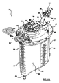
本開示の原理による体外血液回路リザーバ20を、図1Aおよび1Bに示す。リザーバ20は、ハウジング22および静脈入口アセンブリ24を含む。一部の実施形態では、本開示のリザーバは、心臓切開手術用リザーバと静脈リザーバとの組み合わせとして機能することが可能であり、図1Aおよび図1Bは、オプションの心臓切開手術用アセンブリ26を反映している。静脈構成要素の詳細は、以下に提供する。しかしながら、大まかに言えば、ハウジング22は、主チャンバ28を画定する。静脈入口アセンブリ24は、ハウジング22によって維持されて、静脈チャンバ30を形成するが、このチャンバを通って、静脈ダウンチューブ32からの静脈血液流れが、主チャンバ28中に方向付けられる。1または2以上のルアーポート34が、静脈ダウンチューブ32から延在して、他の補助回路構成要素から静脈ダウンチューブ32中への血液の送達を容易化する。提供される場合、心臓切開手術用アセンブリ26もまた、ハウジング22に保持されて、心臓切開手術用チャンバ36を確立し、このチャンバを通って、1または2以上の心臓切開手術用入口ポート38からの心臓切開手術血液流れが、主チャンバ28中に方向付けされる。心臓切開手術用アセンブリ26が含まれるかどうかとは無関係に、本開示の一部の態様は、静脈ダウンチューブ32とルアーポート34との間の関係に関し、これが、ルアーポート34を通る血液流れの、ダウンチューブ32を通る一次静脈血液流れとの静かで実質的に非乱流の合流を確立する。静脈ダウンチューブ32に対するルアーポート34のこの関係または配設とは別として、リザーバ20は、非常に様々な他の形態をとり得る。例えば、本開示の実施形態で有用なリザーバの特徴が、米国特許公開第2010/0268148号(「Cardiotomy and Venous Blood Reservoir and Method」という題名)に記述されているが、その教示を参照して本明細書に組み込む。したがって、本開示は、以下に説明するように、ハウジング22、静脈入口アセンブリ24、または心臓切開手術用アセンブリ26には限られない。
An extracorporeal
さらに図2を参照して、ハウジング22は、様々な形態をとり得るが、一部の実施形態では、フレーム40、蓋42、およびタレット44を含む。フレーム40および蓋42は組み合わさって主チャンバ28を画定し、蓋42およびタレット44は、心臓切開手術用入口ポート38などの1または2以上のポートを保持する。
Still referring to FIG. 2, the housing 22 may take a variety of forms, but in some embodiments includes a frame 40, a lid 42, and a
フレーム40は、上部側部50および下部側部52を画定する中空の本体である。蓋42は上部側部50に組み立てられ、下部側部52は、オプションとして、輪郭形成された形状を有し、さもなければ主チャンバ28に流体接続される排出ポート54で終端する。フレーム40は図示する概して円筒形状を有し得るが、箱形状などの他の形状も容認可能である。オプションとして、フレーム40は、介護人の手によって便利に把持されるような寸法のハンドルセグメント56を形成する。関連する実施形態では、ハンドルセグメント56は、オプションとして、例えば、ハンドルセグメント56を通って形成されたチャネル58を介して、リザーバ20の個別の支持構造(例えば、点滴スタンドなどのまっすぐな支柱)に対する装着を容易化するように構成される。 The frame 40 is a hollow body that defines an upper side 50 and a lower side 52. The lid 42 is assembled to the upper side 50 and the lower side 52 optionally has a contoured shape and terminates at an exhaust port 54 that is otherwise fluidly connected to the main chamber 28. The frame 40 may have a generally cylindrical shape as shown, but other shapes, such as a box shape, are acceptable. Optionally, the frame 40 forms a handle segment 56 sized to be conveniently grasped by the caregiver's hand. In a related embodiment, the handle segment 56 is optionally against an individual support structure of the reservoir 20 (eg, a straight post such as an infusion stand), eg, via a channel 58 formed through the handle segment 56. Configured to facilitate installation.
蓋42は、フレーム40に装着され(または、代替的にはその一部として形成され)、ルアーコネクタ、換気コネクタ、圧力逃し弁ハウジングコネクタなどの1または2以上のコネクタ60を保持または画定する。さらなるコネクタを形成するまたはこれに蓋42を備えることが可能である、および/または図示するコネクタ60のうちの1つまたは全てを省略することが可能である。さらに、蓋42は、オプションのチューブ管理アセンブリ64を選択的に受容して保持するように構成された取り付け金具62を形成し得る。とにかく、蓋42は、以下に説明するように、タレット44を回転可能に受容するような寸法の第1のアパーチャ66と、静脈アセンブリ24の対応する構成要素を回転可能に受容するような寸法の第2のアパーチャ68とを形成する。この点で、第1および第2のアパーチャ66、68は各々が、蓋42に対して、それぞれ、タレット44および静脈アセンブリ構成要素の回転可能な装着を促進するようにオプションとして構成されたリッジ70、72(図2に最もよく示す)によって囲まれている。
The lid 42 is attached to (or alternatively formed as part of) the frame 40 and holds or defines one or
タレット44は、一部の実施形態では、心臓切開手術用入口ポート38、ルアーコネクタ82、一次コネクタ84などの一連のコネクタを保持するハブ80を含む。これより多いまたは少ないコネクタに、他の実施形態ではタレット44を備えることが可能である。とにかく、タレット44を蓋42の第1のアパーチャ66内で組み立てると、タレット44は、蓋42に対して(および、したがってフレーム40に対して)回転可能である。
The
蓋42および/またはタレット44は、上述のそれとは異なる構成を有し得る。例えば、回転可能な特徴部は、オプションであって省略可能である。大まかに言えば、ハウジング22は、主チャンバ28と、リザーバへの静脈血液および心臓切開手術血液用の流路またはポートを確立し、リザーバ20からの処理された血液用の流路またはポートを確立する。
The lid 42 and / or
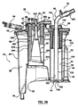
静脈アセンブリ24は、静脈入口サブアセンブリ90、ボウル92、(図1B)静脈フィルター94(図1Bおよび2に一般的に参照される)、および静脈消泡器96を含む。大まかに言えば、静脈血液および他の血液は、静脈入口サブアセンブリ90からボウル92に、次に静脈フィルター94に方向付けされる。静脈消泡器96は、ボウル92内に蓄積された血液と関連するあらゆる泡と相互作用するように位置付けされる。より具体的には、ボウル92および静脈フィルター94は組み合わさって、静脈チャンバ30の少なくとも一部を画定し、静脈消泡器96は、静脈チャンバ30内での泡すすぎに晒される。
The venous assembly 24 includes a venous inlet subassembly 90, a bowl 92, (FIG. 1B) a venous filter 94 (generally referenced in FIGS. 1B and 2), and a
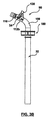
静脈入口サブアセンブリ90は、ダウンチューブ32、ルアーポート34、および装着取り付け金具100を含む。装着取り付け金具100は、静脈入口サブアセンブリ24の蓋42の第2のアパーチャ68との組み立てを容易化する。ダウンチューブ32は、対向する入口端部と出口端部104、106間に延在しこれらの端部で開放している一次ルーメン102を形成または画定する。これらの慣例を念頭に置くと、ダウンチューブ32は、入口端部104に隣接する入口セクション108と、出口端部106に隣接する出口セクション110とを概して画定するものであると述べることが可能である。最終的に組み立てられると、入口セクション108は、ハウジング22の外部に置かれ、一方、出口セクション110は、ハウジング22の内部に置かれる。
Venous inlet subassembly 90 includes
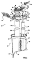
ダウンチューブ32の入口セクション108を含む静脈入口サブアセンブリ90は、図3A〜図3Cにより詳細に示す。図3Cは、さもなければ入口端部104で開放されているダウンチューブの一次ルーメン102をより完全に示す。一次ルーメン102は、中心軸Cを画定する。図3Cに示す入口セクション108の部分に少なくとも沿って、一次ルーメン軸Cは、線形であり得る。
The venous inlet subassembly 90 including the
ルアーポート34は各々が、コネクタ本体112およびルアーアダプタもしくは接続金具114(図3Bおよび3Cの図では省略されている)を含む。基準点として、図3A〜図3Cに反映されている静脈入口サブアセンブリ90は、ルアーポートコネクタ本体112のうちの2つ112a、112bを含むが、これより多いまたは少ない任意の他の数も容認可能である。とにかく、ポートコネクタ本体112a、112bの各々は、対応するルアーアダプタ114に対して組み立てるように構成された受容端部116を形成または画定する。
Each
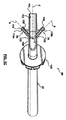
ルアーポートコネクタ本体112a、112bおよび、特に、ダウンチューブ32に対するそれらの関係もしくは配設は、同一であり得るため、第1のルアーポートコネクタ本体112aの次の記述は、第2のコネクタ本体112bにも等しくあてはまる。図3Cを詳細に参照すると、ポートコネクタ本体112aは、筒形状を有し、内部通路120を画定または形成している。通路120は、例えば、ダウンチューブ32の壁の厚さを通過する流れ開口部122を介して、ダウンチューブ32の一次ルーメン102に対して流体的に開放されている。したがって、受容端部116でポートコネクタ本体112a中に導入された流体流れは、通路120を通って一次ルーメン102中に方向付けされる。一部の実施形態では、コネクタ本体112a、および、したがって通路120は、ダウンチューブ32からの延在の全体にわたって線形である。とにかく、一次ルーメン102中への流れ開口部122は、ダウンチューブ入口端部104の下流で形成され、通路120の軸中心線Aは(少なくとも流れ開口部122で)、図3Cに反映されているように、一次ルーメン102の中心軸Cに対して非垂直である。別な言い方をすれば、延在角度αは、軸中心線Aの中心軸Cとの交点によって形成される。延在角度αは、90°未満であり、一部の実施形態では、1°〜85°の範囲にあり、他の実施形態では15°〜75°の範囲にある。
Since the luer
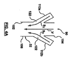
一次ルーメン102に対する内部通路120の角度付きの(すなわち、非垂直の)関係が、ポートコネクタ本体112aからの液体流れの一次ルーメン102中の既存の一次液体流れ(すなわち、入口端部104に送達され、したがって、ポートコネクタ本体流れ開口部122の上流にある液体流れ)との非乱流合流を促進する。例えば、図4Aは、ダウンチューブ32の入口セクション108と、ルアーポートコネクタ本体112a、112bを通る液体流れの簡略化された略図である。基準点として、体外血液回路内で用いられるとき、静脈血液は、入口端部104(一般的な言及)で一次ルーメン102に入るが、図4Aの矢印Vは、一次ルーメン102に沿った静脈血液の(すなわち一次の)流路を表している。二次血液流れ(例えば、動脈フィルターパージ流れ)は、二次流路矢印S1、S2で表されるように、ルアーポートコネクタ本体112a、112b中に方向付けされる。図4Aに示すように、二次流路S1、S2は、対応する流れ開口部122を介して、一次流路Vに対して非垂直角度で一次ルーメン102に入る。この角度付き関係は、二次流路S1、S2に沿って入ってくる二次血液流れが、一次流路Vに沿って移動する静脈血液中に乱流を誘発する可能性を減少させる。
The angled (ie, non-vertical) relationship of the
図4Aは、ルアーポートコネクタ本体112a、112bがダウンチューブ32に対して長手方向で整列している(すなわち、対応する流れ開口部122が整列している)ことを反映しているが、他の実施形態では、ルアーポートコネクタ本体112a、112bは長手方向にずらすことが可能である。同様に、ルアーポートコネクタ本体112a、112bならびに対応する内部通路120は、線形であるとして示されているが、他の実施形態では、1または2以上の屈曲部を、ダウンチューブ32から延長線上で、ルアーポートコネクタ本体112a、112bの一方または双方の長さに沿って生じさせることが可能である。これらの代替的な構造によって、ポートコネクタ本体軸中心線Aによって画定されるような非垂直延在角度α(図3C)は、上述したように、少なくとも流れ開口部122で提示される。
4A reflects that the luer
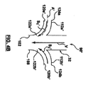
図4Bは、第1および第2のルアーポートコネクタ本体112a’、112b’と共に、上述した静脈ダウンチューブ32の入口セクション108を含む別の実施形態の静脈入口サブアセンブリ90’の一部分を略図で示す。ルアーポートコネクタ本体112a’、112b’は、ダウンチューブ32から延在し、各々が、対応する流れ開口部122a’、122b’を介して一次ルーメン102に対して流体的に開放している内部通路120a’、120b’を画定する。図4Bに暗示される構造によって、ルアーポートコネクタ本体112a’、112b’はダウンチューブ32から非線形的に延在する。別な言い方をすれば、内部通路120a’、120b’によって画定される軸中心線A’は、非線形すなわち湾曲している。この構造によって、ルアーポートコネクタ本体112a’、112b’の入口側部124a、124bは、一次ルーメン102の中心軸C(図3C)に対して実質的に垂直に配設することが可能である。しかしながら、ルアーポートコネクタ本体112a’、112b’は、対応する流れ開口部122a’、122b’において、対応する軸中心線A’が、一次ルーメン102に対して角度が付いているすなわち非垂直であるように、構成し、配設される。その結果、二次流路S1’、S2’に沿った二次血液流れは、一次流路Vに沿った静脈血液流れと穏やかに合流し、誘発される乱流は、もしあったとしても最小になる。
FIG. 4B schematically illustrates a portion of another embodiment venous inlet subassembly 90 ′ that includes the
図3A〜図3Cに戻ると、静脈入口サブアセンブリ90は、ダウンチューブ32から突出するさらなるポートを含むことが可能である。例えば、温度サンプリングポート130を、ルアーポートコネクタ本体112a、112bに隣接するダウンチューブ32に組み立てることが可能である。温度サンプリングポート130は一次ルーメン102に対して流体的に開放されているが、対応する内部通路は、一次ルーメン102に対して垂直に配設されたりされなかったりし得る。温度サンプリングポート130は液体流れを一次ルーメン102中に送達するために用いられているわけではないため、ルアーポートコネクタ本体112a、112bによって対処される乱流という懸案は存在しない。例えば、鞘(図示せず)は、温度プローブ(図示せず)と結合する温度サンプリングポート130中に埋め込むことが可能であり、これで、温度サンプリングポート130を一次ルーメン102から流体的に隔離する。
Returning to FIGS. 3A-3C, the venous inlet subassembly 90 may include additional ports that protrude from the
図1A〜図2に戻ると、静脈アセンブリ24の残余の構成要素は、図面に暗示し得るまたは暗示し得ない様々な形態をとることが可能である。例えば、ボウル92は、床表面150を形成し、一部の構造では、ハウジング22の一体形成された構成要素であり、代替的には、ハウジング22およびボウル92は、個別に形成して、次いで組み立てることが可能である。床表面150は、静脈血液流れを静脈チャンバ30内で誘導するまたは方向付けするように働き、そのため、静脈チャンバ30は、ダウンチューブ32の出口端部106での入口および静脈フィルター94での出口を有するものと見なすことが可能である。床表面150は、オプションとして、図1Bに反映されている輪郭形成された領域(例えば、傘形状)を形成するが、他の様々な形状も容認可能である。図示する1つの実施形態では、ボウル表面150の湾曲は、ダウンチューブ32から静脈フィルター94への接線方向移行によって泡を上方に方向付けするように構成される。このオプションの特徴は、乱流を防止または最小化して、泡の完全性を維持する。
Returning to FIGS. 1A-2, the remaining components of the venous assembly 24 may take a variety of forms that may or may not be implied in the drawings. For example, the bowl 92 forms the floor surface 150 and, in some constructions, is an integrally formed component of the housing 22; alternatively, the housing 22 and the bowl 92 are formed separately and then It is possible to assemble. The floor surface 150 serves to guide or direct venous blood flow within the
静脈フィルター94は、篩材料(例えば、105ミクロンの篩)などの静脈血液フィルタリング用に従来用いられてきた形式に釣り合った形態をとることが可能である。一部の構造では、静脈フィルター94は、環状のリングとして形成されたひだのある篩である。静脈フィルター94は、ケージ164に組み立てることが可能であり、これが次に、図示するようにボウル92に装着される。リング形状の静脈フィルター94は、形状が概して円筒形であり得るかまたはテーパー形状を有し得る。
The
静脈消泡器96は、オプションとしてシメチコンなどの泡止め剤で被覆された静脈血液消泡目的で従来用いられている材料(例えば、ポリウレタン発泡体)で形成される。一部の実施形態では、ケージ164は、ダウンチューブ出口端部106から長手方向に離間した位置でダウンチューブ32の周りで静脈消泡器96に保持されるように構成される。静脈消泡器96の他の構造および配設もまた想定される。例えば、静脈消泡器96は、ダウンチューブ32に直接に装着することが可能である。さらに別の実施形態では、静脈消泡器96は省略することが可能である。
The
上記の構造では、ダウンチューブ32中への静脈血液流れは、一次ルーメン102によって出口端部106に方向付けされる。静脈血液は次に、出口端部106から、ボウル92の床表面150上に分注される。静脈血液はボウル92内に蓄積し、床表面150は、静脈血液流れを静脈フィルター94に方向付けし、ここで、静脈血液が主チャンバ28に入る前に適切な濾過が発生する。上述したように、ボウル床表面150のオプションとしての傘様形状が、乱流を最小化し、泡の完全性を維持するが、それは、血液流れがダウンチューブ32から静脈フィルター94に移行するからである。静脈消泡器96の先端部170は、静脈血液が静脈消泡器96と不必要に相互作用しないように、上記の静脈血液流路からずらされている。むしろ、静脈チャンバ30内の静脈血液と関連するいかなる泡も、上方向に上ってからやっと、静脈消泡器96と接触して、所望の消泡を達成する。
In the above configuration, venous blood flow into the
心臓切開手術用アセンブリ26は、提供される場合、一部の実施形態では、静脈アセンブリ24からずれている。図1Bに最もよく示すように、心臓切開手術用アセンブリ26は、フレームワーク200、ディッシュ202、心臓切開手術用フィルター204、および心臓切開手術用消泡器206を含み得る。大まかに言えば、フレームワーク200は、心臓切開手術用フィルター204および心臓切開手術用消泡器206を保持する。ディッシュ202は、心臓切開手術液体流れを心臓切開手術用入口ポート38からフレームワーク200に方向付けし、フレームワーク200は次に、心臓切開手術液体流れを、誘導表面208を介して心臓切開手術用フィルター204に方向付けする。フィルタリングされた心臓切開手術液体は、次いで、以下に説明するように主チャンバ28に方向付けされる。さらに、心臓切開手術用消泡器206は、心臓切開手術用チャンバ36に送達され、これによって保持される心臓切開手術液体の主として泡部分と選択的に相互作用するように位置付けされる。
If provided, the open heart surgical assembly 26 is offset from the venous assembly 24 in some embodiments. As best shown in FIG. 1B, the open heart surgical assembly 26 may include a framework 200, a dish 202, a open heart
フレームワーク200は、様々な形態をとり得るし、一部の構造では、内側支柱212、床214、および外側フレーム216を含む。内側支柱212は、直径が先端部220から床214にかけて徐々に増す、図示するように概して円筒形状を取り得る。先端部220は、ディッシュ202からの液体の非乱流流れを促進するように丸めることが可能であり、支柱212の外側誘導表面208は平滑である。フレームワーク200は、ハウジング22と一体的に、かつ均一に形成する、または、ハウジング22とは分離して形成して次いでこれに対して組み立てることが可能である。
The framework 200 can take a variety of forms, and in some configurations includes an
床214は、内側支柱212から半径方向外向きかつ下向きに延在し、一部の構造では、心臓切開手術用フィルター204の一部分を保持するように適合される。床214は、図1Bに反映される、静脈アセンブリ24に向かう一般的な流れ方向を画定する角度付き構成を取ることが可能である。代替的には、他の形状および/または流れ方向もまた容認可能である。
The
外側フレーム216は、内側支柱212の反対側の床214から延在し、心臓切開手術用消泡器206を支持し、かつ保持するように構成される。また、外側フレーム216は、心臓切開手術用フィルター204を支持する支援と成り得る。
The outer frame 216 extends from the
心臓切開手術用フィルター204は、心臓切開手術血液の濾過目的で従来用いられてきたタイプのものであり得るし、したがって、フェルト材料(例えば、30ミクロンの奥行きまたはメッシュのフィルター)であり得る。一部の構造では、心臓切開手術用フィルター204は、リングとして形成され、フレームワーク200を囲んでいるひだ付きの奥行きまたはメッシュのフィルターである。
The
心臓切開手術用消泡器206は、心臓切開手術液体の消泡に従来用いられてきたタイプ(例えば、ポリウレタン発泡体)のものでもあり、床214から離間されるようにフレームワーク200に組み立てられる。この構造で、床214に沿った心臓切開手術液体の流れは、心臓切開手術用消泡器206と必ずしも相互作用する必要はない。
The
ディッシュ202はじょうご様形状を有し得て、中心アパーチャ230(一般的な言及)を形成している。中心アパーチャ230は、内側支柱212を中心として同軸的に配置され、心臓切開手術液体流れを、アパーチャ230を介して心臓切開手術用入口ポート38から誘導表面208に方向付けするように構成される。最終的に構成されると、内側支柱212および心臓切開手術用フィルター204は組み合わされて、心臓切開手術用チャンバ36を少なくとも部分的に画定し、誘導表面208および床214は、心臓切開手術用チャンバ36を通る流路を画定する。
The dish 202 may have a funnel-like shape, forming a central aperture 230 (general reference). The central aperture 230 is coaxially disposed about the
より特定的には、心臓切開手術用入口ポート38を介してリザーバ20に入る心臓切開手術液体は、ディッシュ202によって内側支柱212に方向付けされる。心臓切開手術液体は、中心アパーチャ230を介してディッシュ202から誘導表面208に移動する。心臓切開手術液体は(重力によって)、誘導表面208に沿って、心臓切開手術用フィルター204に流れる。さもなければ心臓切開手術用フィルター204の「背後の」誘導表面208に沿って蓄積する心臓切開手術液体と関連するいかなる泡も、上向きに上って、心臓切開手術用消泡剤206と接触する。心臓切開手術液体は、次いで、心臓切開手術用フィルター204によってフィルタリングされ、次に、フィルタリングされた静脈血液とより完全に混合されるように、主チャンバ28に方向付けされる。
More specifically, the cardiotomy fluid entering the
心臓切開手術用アセンブリ26は、上記のものと構造または構成が異なることがあり得る。例えば、心臓切開手術用アセンブリ26は、静脈アセンブリ24に対して積層された構造を有し得る。さらに別の実施形態では、心臓切開手術用アセンブリは、完全に省略することが可能である。 The open heart surgical assembly 26 may differ in structure or configuration from that described above. For example, the open heart surgical assembly 26 may have a structure laminated to the venous assembly 24. In yet another embodiment, the open heart surgical assembly can be omitted entirely.
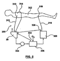
リザーバ20が心臓切開手術用アセンブリ26を組み込むかどうかとは無関係に、リザーバ20は、概して図5に示すように、体外血液回路300に組み込むことが可能である。回路300は、患者302に接続されるが、一般的に、ポンプ304、人工心肺306、および動脈フィルター308を含む。静脈カニューレ310(一般的な言及)は、静脈血液を、静脈ライン312を介して患者302からリザーバ20に送達する。心臓切開手術用ライン314は、心臓切開手術用流れを、直接にリザーバ20にまたは、個別の心臓切開手術用リザーバに方向付けするが、そのリザーバの出力がリザーバ20に送達される。とにかく、ポンプ304は、リザーバ20から人工心肺306(熱交換器特徴部を組み込んだり組み込まなかったりし得る)への血液流れを制御する。最終的に、酸素添加された血液流れは、人工心肺306から動脈フィルター308に方向付けされ、次に、復帰ライン316および動脈カニューレ318を介して患者302に戻るように方向付けされる。図1Bおよび5を相互参照すると、静脈ライン312は、静脈ダウンチューブ32の入口端部104と流体的に結合されている。動脈フィルター308を備えているパージポート320は、ルアーポート34のうちの1つに流体的に接続されている。この点で、パージポート320は、選択されたルアーポート34に直接に接続することが可能である。代替的には、サンプリングマニホルド(図示せず)を提供することが可能である。サンプリングマニホルドの動脈ラインは、動脈フィルターパージポート320に接続され、サンプリングマニホルドの静脈ラインは選択されたルアーポート34に接続される。回路300の他の構成要素もまた、ルアーポート34のうちの選択された1つに接続することが可能である。例えば、図5は、ルアーポート34のうちの第2のものに(直接的にまたはオプションのサンプリングマニホルドを介して)流体的に接続されている人工心肺306と関連するパージポート322を反映している。代替的には、他の補助装置(例えば、血液濃縮器)を、ルアーポート34のうちの選択された1つに接続することが可能である。さらに別の応用物では、利用可能なルアーポート34のうちの1または2以上を不使用にして、したがって流体的に閉じられる。
Regardless of whether the
体外血液回路300の動作中、患者302からの静脈血液流れは、ダウンチューブ32に入り、選択されたルアーポート34を介してダウンチューブ32に入る補助血液流れと混合される。ダウンチューブ32の一次ルーメン102に対する対応するルアーポートコネクタ本体112の角度の付いた(すなわち、非垂直の)配設のため、補助血液流れのダウンチューブ32内での静脈血液流れとの合流による乱流は、たとえ存在しても、最小化される。その結果、ダウンチューブ32中への静脈血液流れによって運ばれる全体の気泡は、あからさまには破裂せず、リザーバ20から容易に除去される。大まかに言えば、気泡全体は、リザーバ20中(例えば、静脈チャンバ30内)の液体の表面に浮遊し、排出口を介して大気中に散逸する。角度付きルアーポートコネクタ本体112が、GMEの除去をより困難にする気泡全体の発生を最小化する。リザーバ20の全体的なGME成績が向上し、より大きい孔寸法の静脈フィルター94が実装可能となり、これによって、血液損傷が最小化される(また、動的なホールドアップも軽減可能である)。
During operation of the extracorporeal blood circuit 300, the venous blood flow from the
ルアーポートが対応する静脈ダウンチューブに対して全く垂直である従来の構造と比較して本開示の角度付きルアーポートの性能を評価するために試験が実施された。特に、リザーバは、図1Bの構成に従って構築され、同様に、比較用のリザーバは、ルアーポートが、静脈ダウンチューブルーメンに対して90°の角度で配設されたことを除けば実質的に同じ構造を有していた。サンプル用のリザーバおよび比較用リザーバは、100mL/分で連続的な空気のボーラスが、4.5L/分のグリセロール流量でダウンチューブに送達される試験に供された。さらに、グリセロールが、様々な流量で、ルアーポートの一方または双方に連続的に送達された。2分間の試験期間の経過にわたって、静脈フィルターを通過する空気の量(マイクロリットル)が、測定されて記録された。試験の結果を図6に示す。図示するように、より多量の(静脈フィルターを通過する)空気が、垂直のルアーポートの比較例の場合に見受けられ、次いで、本開示の角度付きルアーポート構造の場合で立証された。例えば、補助液体流れが500mL/分の速度で双方のルアーポート中に導入された場合、角度付きルアーポートを組み込んだサンプルリザーバと比較して、6倍を超える量の空気が、従来のすなわち比較例のリザーバの静脈フィルターを通過した。この発見は、乱流に晒される静脈ダウンチューブを通る一次液体流れによって運ばれる気泡全体が、その寸法(例えば、GME)が減少し、したがって、静脈フィルターを通過することが可能であることを示している。 A test was conducted to evaluate the performance of the disclosed angled luer port compared to a conventional structure where the luer port is quite perpendicular to the corresponding venous downtube. In particular, the reservoir is constructed according to the configuration of FIG. 1B, and similarly, the comparative reservoir is substantially the same except that the luer port is disposed at a 90 ° angle to the venous downtube lumen. Had a structure. The sample reservoir and comparative reservoir were subjected to a test in which a continuous air bolus at 100 mL / min was delivered to the downtube at a glycerol flow rate of 4.5 L / min. In addition, glycerol was continuously delivered to one or both luer ports at various flow rates. Over the course of the 2 minute test period, the amount of air (in microliters) passing through the venous filter was measured and recorded. The test results are shown in FIG. As shown, a greater amount of air (passing through the venous filter) was found in the case of the vertical luer port comparative example, and then demonstrated in the case of the angled luer port structure of the present disclosure. For example, if an auxiliary liquid stream is introduced into both luer ports at a rate of 500 mL / min, more than six times the amount of air compared to a sample reservoir that incorporates an angled luer port Passed venous filter in example reservoir. This finding indicates that the entire bubble carried by the primary liquid flow through the venous downtube exposed to turbulence is reduced in its dimensions (eg, GME) and can therefore pass through the venous filter. ing.
本開示の他の実施形態は、リザーバの動的ホールドアップ性能を向上させ得る静脈アセンブリ24(図1B)での1または2以上のオプションの構成要素を提供する。基準点として、動的ホールドアップのためには、第一の目標は、血液がリザーバを通って流れている間に、灌流技師にとって入手可能でない血液の量を減少させることである。リザーバの静脈部分の場合、これは、高い流量(例えば、7L/分)で開放するときに静脈フィルターまたはスクリーンによって渋滞させられる血液の量、またはより簡単には、リザーバ/主チャンバ中の液体レベルを超える静脈チャンバ(または静脈ケージ)内の液体の量として定義される。 Other embodiments of the present disclosure provide one or more optional components in the venous assembly 24 (FIG. 1B) that can improve the dynamic holdup performance of the reservoir. As a reference point, for dynamic holdup, the primary goal is to reduce the amount of blood that is not available to the perfusion engineer while blood is flowing through the reservoir. In the case of the venous portion of the reservoir, this is the amount of blood that is congested by the venous filter or screen when opening at a high flow rate (eg 7 L / min), or more simply, the liquid level in the reservoir / main chamber Is defined as the amount of fluid in the venous chamber (or venous cage).
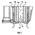
これらを念頭に置いて、図7は、本開示のリザーバで役に立つ代替の静脈アセンブリ24’の一部分を示す。静脈アセンブリ24’は、上述の静脈アセンブリに類似していて、ダウンチューブ32、ボウル92、およびケージ164(静脈フィルター(図示せず)を支持する)を含む。加えて、ダウンチューブ出口端部106から近接して延在する体積ディスプレーサー400が、ダウンチューブ32の周りに形成される。体積ディスプレーサー400は、中実で、管状の本体であり、ケージ164から(そして次にそれによって担持される静脈フィルターから)半径方向に離間されている。再循環経路402が、ダウンチューブ32と体積ディスプレーサー400との間でオプションとして画定される(また、再循環ポート(図示せず)と流体連通している)。代替的には、体積ディスプレーサー400は、ダウンチューブ32に直接に当接し得る。とにかく、体積ディスプレーサー400は、原則として、ダウンチューブ30とケージ164との間の解放体積を減少させる(すなわち、体積ディスプレーサー400がなければ、利用可能なスペースすなわち体積はより大きくなる)。この配設では、体積ディスプレーサー400は、実質的に全てのリザーバ液体レベルで動的ホールドアップを改善し、乱流を惹起させない。図7に反映されるように、体積ディスプレーサー400は、気泡Bを静脈フィルターの表面に方向付けする(さもなければケージ164に保持される)。静脈ケージの表面に直接向かう泡Bの流路は、体積ディスプレーサー40に、泡Bが乱流中を循環するのを妨げる羽根を追加することによってさらに向上する。とにかく、体積ディスプレーサー400は、泡Bを、それが分裂してGMEになる可能性が出る前に、表面に向かって加速させる働きをする(断面積は小さいほど流速が高い)。
With these in mind, FIG. 7 shows a portion of an alternative venous assembly 24 'useful with the reservoirs of the present disclosure. The venous assembly 24 'is similar to the venous assembly described above, and includes a
本開示のリザーバは、以前の設計にない画期的な向上を提供する。静脈ダウンチューブを持つ角度付きルアーポートを組み込むことによって、本開示のリザーバは、対応するルアーポートを通って連続的なパージまたはボーラスを走行させるときダウンチューブ内での乱流を減少させ、それによりGME成績が優れたものになる結果をもたらす。 The reservoir of the present disclosure provides a breakthrough improvement over previous designs. By incorporating an angled luer port with a venous downtube, the reservoir of the present disclosure reduces turbulence in the downtube when running a continuous purge or bolus through the corresponding luer port, thereby GME results will be excellent.
本開示を好ましい実施形態を参照して説明したが、本開示の趣旨および範囲から逸脱することなく、形態および詳細に対して変更が可能であることを、当業者は認識するであろう。 Although the present disclosure has been described with reference to preferred embodiments, workers skilled in the art will recognize that changes may be made in form and detail without departing from the spirit and scope of the disclosure.
Claims (20)
主チャンバを画定するハウジングと、
前記主チャンバに流体接続された排出ポートと、
前記ハウジングに装着される静脈入口サブアセンブリであって、
対向する入口端部と出口端部との間を延在し、かつこれらの端部で開放している一次ルーメンを形成するダウンチューブであって、前記入口端部に隣接する入口セクションと前記出口端部に隣接する出口セクションとを画定する、ダウンチューブと、
前記入口セクションから延在し、流れ開口部で前記一次ルーメンに対して開放している通路を形成する第1のルアーポートコネクタ本体と、を有し、
前記ポートコネクタ本体が、前記通路から前記一次ルーメン中への流体流れの流路が前記一次ルーメンに沿った流体流れの流路と90°未満の角度で合流するように、前記入口セクションに対して配設された、静脈入口サブアセンブリと、を備え、
前記静脈入口サブアセンブリが、前記入口セクションおよび前記ポートコネクタ本体を前記ハウジングの外側に位置付け、前記出口セクションを前記ハウジング内に位置付けるように配設され、体外血液回路リザーバデバイスがさらに、
前記出口端部と前記排出ポートとの間で流体的に前記ハウジング内に維持される静脈フィルターを備えている、
ことを特徴とするリザーバデバイス。 An extracorporeal blood circuit reservoir device comprising:
A housing defining a main chamber;
An exhaust port fluidly connected to the main chamber;
A venous inlet subassembly attached to the housing, comprising:
A downtube extending between and opposite the inlet end and forming a primary lumen open at these ends, the inlet section adjacent to the inlet end and the outlet A down tube defining an exit section adjacent to the end;
A first luer port connector body extending from the inlet section and defining a passage open to the primary lumen at a flow opening;
The port connector body is relative to the inlet section such that a fluid flow path from the passage into the primary lumen meets a fluid flow path along the primary lumen at an angle of less than 90 °. A venous inlet subassembly disposed;
The venous inlet subassembly is disposed to position the inlet section and the port connector body outside the housing and the outlet section within the housing; and the extracorporeal blood circuit reservoir device further comprises
Comprising a venous filter maintained fluidly in the housing between the outlet end and the outlet port;
A reservoir device characterized by that.
請求項1に記載のリザーバデバイス。 The extension angle defined by the intersection of the axial centerline of the passage with the central axis of the primary lumen is less than 90 °;
The reservoir device of claim 1.
請求項2に記載のリザーバデバイス。 The extension angle is in the range of 1 ° to 85 °,
The reservoir device according to claim 2.
請求項2に記載のリザーバデバイス。 The axial center line is linear along the entire length of the port connector body;
The reservoir device according to claim 2.
請求項2に記載のリザーバデバイス。 The axial center line is non-linear along the length of the port connector body;
The reservoir device according to claim 2.
請求項1に記載のリザーバデバイス。 A luer lock assembled to the port connector body;
The reservoir device of claim 1.
前記入口セクションから延在し、通路を形成する第2のルアーポートコネクタ本体をさらに備え、
前記第2のポートコネクタ本体が、前記第2のポートコネクタ本体の前記通路から前記一次ルーメン中への流体流れの流路が、前記一次ルーメンに沿った流体流れの流路と90°未満の角度で合流するように、前記入口セクションに対して配設される、
請求項1に記載のリザーバデバイス。 The venous inlet subassembly comprises:
A second luer port connector body extending from the inlet section and forming a passage;
The second port connector body has a fluid flow path from the passage of the second port connector body into the primary lumen and an angle of less than 90 ° with the fluid flow path along the primary lumen. Arranged at the inlet section to meet at
The reservoir device of claim 1.
請求項7に記載のリザーバデバイス。 The passage of each of the port connector bodies defines an axial centerline, and further, the intersection of each of the axial centerlines with the central axis of the primary lumen forms an extension angle of less than 90 °.
8. A reservoir device according to claim 7.
請求項7に記載のリザーバデバイス。 The second port connector body is spaced circumferentially from the first port connector body;
8. A reservoir device according to claim 7.
請求項7に記載のリザーバデバイス。 The first port connector body is longitudinally aligned with the second port connector body;
8. A reservoir device according to claim 7.
請求項7に記載のリザーバデバイス。 The venous inlet assembly further comprises a sampling port body extending from the inlet section and fluidly open to the primary lumen;
8. A reservoir device according to claim 7.
前記床表面が、前記流体流れを前記床表面の中心領域から前記床表面の半径方向外向きの領域に接線方向に移行させるように適合された湾曲を画定する、
請求項1に記載のリザーバデバイス。 Further comprising a bowl disposed within the housing and forming a floor surface disposed to receive fluid flow from an outlet end of the downtube;
The floor surface defines a curvature adapted to tangentially transfer the fluid flow from a central region of the floor surface to a radially outward region of the floor surface;
The reservoir device of claim 1.
前記心臓切開手術用出口と前記排出ポートとの間で流体的に前記ハウジング内に配置された心臓切開手術用フィルターと、
をさらに備えている、
請求項1に記載のリザーバデバイス。 A cardiotomy inlet assembly mounted to the housing and defining a cardiotomy inlet and a cardiotomy outlet;
A cardiotomy filter disposed fluidly within the housing between the cardiotomy outlet and the drain port;
Further equipped with,
The reservoir device of claim 1.
請求項13に記載のリザーバデバイス。 The venous filter and the cardiotomy surgical filter are disposed to direct fluid flow into the main chamber;
The reservoir device according to claim 13.
請求項1に記載のリザーバデバイス。 Fluid that flows from the first port connector body through the primary lumen such that disposition of the first port connector body relative to the down tube is less than 500 mL / min through the passage. Configured to not induce turbulence in the inside,
The reservoir device of claim 1.
患者に挿管されて、静脈血を受容するための静脈カニューレと、
リザーバデバイスであって、
主チャンバを画定するハウジングと、
前記主チャンバに流体接続された排出ポートと、
前記ハウジングに搭載される静脈入口サブアセンブリであって、
対向する入口端部と出口端部で開口部の間を延在する一次ルーメンを形成するダウンチューブであって、前記入口端部に隣接する入口セクションと、前記出口端部に隣接する出口セクションとを画定する、ダウンチューブと、
前記入口セクションから延在し、前記一次ルーメンに対して開放している通路を形成するルアーポートコネクタ本体と、を含む、静脈入口サブアセンブリと、
前記出口端部と前記排出ポートとの間で流体的に前記ハウジング内に維持される静脈フィルターと、を備え、
前記静脈カニューレが、前記ダウンチューブの前記入口端部に流体接続される、リザーバデバイスと、
パージポートを含む動脈フィルターデバイスであって、前記動脈フィルターデバイスが、前記リザーバデバイスの下流で前記排出ポートに流体接続されており、さらに前記パージポートが前記ポートコネクタ本体に流体接続される、動脈フィルターデバイスと、
前記動脈フィルターの下流で患者に挿管するための動脈カニューレと、を備え、
前記静脈カニューレから前記ダウンチューブを通る一次静脈流路が確立され、前記パージポートから前記第1のポートコネクタ本体を通る二次流路が確立され、さらに、前記二次流路が、前記入口セクション内で前記一次静脈流路と90°未満の角度で合流する、
ことを特徴とする回路。 An extracorporeal blood circuit,
A venous cannula to be intubated by the patient and receive venous blood;
A reservoir device,
A housing defining a main chamber;
An exhaust port fluidly connected to the main chamber;
A venous inlet subassembly mounted on said housing, comprising:
A down tube forming a primary lumen extending between the openings at opposite inlet and outlet ends, the inlet section adjacent to the inlet end, and the outlet section adjacent to the outlet end; Defining the down tube, and
A venous inlet subassembly, comprising: a luer port connector body extending from the inlet section and forming a passage open to the primary lumen;
A venous filter that is fluidly maintained in the housing between the outlet end and the outlet port;
A reservoir device, wherein the venous cannula is fluidly connected to the inlet end of the downtube;
An arterial filter device including a purge port, wherein the arterial filter device is fluidly connected to the drain port downstream of the reservoir device, and the purge port is fluidly connected to the port connector body The device,
An arterial cannula for intubating a patient downstream of the arterial filter,
A primary venous flow path is established from the venous cannula through the downtube, a secondary flow path is established from the purge port through the first port connector body, and the secondary flow path is further connected to the inlet section. Merges with the primary venous flow path at an angle of less than 90 °,
A circuit characterized by that.
請求項16に記載の回路。 The extension angle defined by the intersection of the axial centerline of the passage with the central axis of the primary lumen is less than 90 °;
The circuit according to claim 16.
前記患者からの静脈供給源血液を、出口端部を有するダウンチューブの入口端部中に方向付けすることと、
二次供給源血液を、前記出口端部の上流の位置でルアーポートコネクタ本体を通って前記ダウンチューブ中に方向付けすることであって、前記二次供給源血液流れが90°未満の角度で前記静脈供給源血液流れと合流することを含むことと、
前記静脈供給源血液および前記二次供給源血液の混合物を前記出口端部からリザーバチャンバ中に分注することと、
前記混合血液を前記チャンバ内で静脈フィルターを通って誘導することと、
を含む、
ことを特徴とする方法。 A method of collecting and processing a patient's extracorporeal blood during surgery,
Directing venous source blood from said patient into the inlet end of a downtube having an outlet end;
Directing secondary source blood through the luer port connector body into the down tube at a location upstream of the outlet end, wherein the secondary source blood flow is at an angle of less than 90 °. Conjoining with the venous source blood flow;
Dispensing a mixture of the venous source blood and the secondary source blood into the reservoir chamber from the outlet end;
Directing the mixed blood through a venous filter in the chamber;
including,
A method characterized by that.
血液を前記動脈フィルターから前記患者に戻すように方向付けすることと、
前記動脈フィルターから前記ダウンチューブへの血液の部分的な流れを、補助供給源血液としてパージすることと、をさらに備えている、
請求項18に記載の方法。 Directing blood from the reservoir to an arterial filter;
Directing blood back from the arterial filter to the patient;
Purging a partial flow of blood from the arterial filter to the downtube as an auxiliary source blood,
The method of claim 18.
請求項18に記載の方法。 The placement of the connector port body relative to the down tube is at an auxiliary source blood flow rate of less than 500 mL / min through the port connector body, and the secondary source blood flow is disrupted in the primary venous source blood flow. Configured to not induce flow,
The method of claim 18.
Applications Claiming Priority (3)
| Application Number | Priority Date | Filing Date | Title |
|---|---|---|---|
| US13/411,363 US9545472B2 (en) | 2012-03-02 | 2012-03-02 | Extracorporeal blood circuit reservoir with angled venous inlet luer port |
| US13/411,363 | 2012-03-02 | ||
| PCT/US2013/025633 WO2013130258A1 (en) | 2012-03-02 | 2013-02-11 | Extracorporeal blood circuit reservoir with angled venous inlet luer port |
Publications (2)
| Publication Number | Publication Date |
|---|---|
| JP2015508697A true JP2015508697A (en) | 2015-03-23 |
| JP6506557B2 JP6506557B2 (en) | 2019-04-24 |
Family
ID=47757698
Family Applications (1)
| Application Number | Title | Priority Date | Filing Date |
|---|---|---|---|
| JP2014559909A Active JP6506557B2 (en) | 2012-03-02 | 2013-02-11 | Extracorporeal blood circuit reservoir with angled venous inlet luer port |
Country Status (5)
| Country | Link |
|---|---|
| US (2) | US9545472B2 (en) |
| EP (1) | EP2819721B1 (en) |
| JP (1) | JP6506557B2 (en) |
| CN (1) | CN104144718B (en) |
| WO (1) | WO2013130258A1 (en) |
Families Citing this family (9)
| Publication number | Priority date | Publication date | Assignee | Title |
|---|---|---|---|---|
| US9408960B2 (en) | 2013-12-19 | 2016-08-09 | Medtronic, Inc. | Partial radial heat exchanger and oxygenator |
| CA157912S (en) * | 2014-01-31 | 2015-02-26 | Nipro Corp | Blood reservoir |
| CN109069722B (en) * | 2016-02-29 | 2021-05-28 | 索林集团意大利有限责任公司 | Blood Reservoir with Blood Processing Components |
| CN109996573B (en) * | 2016-11-29 | 2021-09-07 | 甘布罗伦迪亚股份公司 | Connector structure, system for extracorporeal blood treatment, and method for priming a fluid chamber of a blood treatment unit |
| IT201700107088A1 (en) * | 2017-09-25 | 2019-03-25 | Eurosets Srl | BLOOD FILTERING DEVICE |
| US11141517B2 (en) | 2018-10-25 | 2021-10-12 | Medtronic, Inc. | Oxygenator |
| JP7449627B2 (en) | 2021-01-17 | 2024-03-14 | インスパイア エム.ディー リミテッド | Shunt with blood flow indicator |
| JPWO2022158466A1 (en) * | 2021-01-25 | 2022-07-28 | ||
| CN116685367B (en) * | 2021-03-25 | 2024-09-10 | 印斯拜尔Md有限公司 | Device for dividing blood between arterial and venous systems |
Citations (9)
| Publication number | Priority date | Publication date | Assignee | Title |
|---|---|---|---|---|
| JPS54156388A (en) * | 1978-05-30 | 1979-12-10 | Baxter Travenol Lab | Improved heart incision storage tank |
| JPH05505542A (en) * | 1990-03-14 | 1993-08-19 | ミネソタ マイニング アンド マニュファクチャリング カンパニー | Rapid change blood handling equipment |
| JPH07500020A (en) * | 1991-06-11 | 1995-01-05 | ジェンザイム・コーポレーション | collection device |
| JP2001503665A (en) * | 1996-11-15 | 2001-03-21 | シー アール バード,インク | Integrated reservoir device for heart and venous blood |
| US20030083678A1 (en) * | 2001-10-26 | 2003-05-01 | Atrium Medical Corporation | Body fluid cartridge exchange platform device |
| JP2007515251A (en) * | 2003-12-22 | 2007-06-14 | メドトロニック・インコーポレーテッド | Extracorporeal blood circuit air removal system and method |
| JP2008188233A (en) * | 2007-02-05 | 2008-08-21 | Jms Co Ltd | Blood inlet port and blood reservoir |
| JP2009106445A (en) * | 2007-10-29 | 2009-05-21 | Ube Junken:Kk | Extracorporeal circuit system and extracorporeal circuit system package |
| JP2012020149A (en) * | 2003-09-04 | 2012-02-02 | Arryx Inc | Apparatus and method for purifying/separating particle |
Family Cites Families (30)
| Publication number | Priority date | Publication date | Assignee | Title |
|---|---|---|---|---|
| CA1144835A (en) | 1978-05-30 | 1983-04-19 | Baxter Travenol Laboratories, Inc. | Cardiotomy reservoir |
| US4422939A (en) | 1979-11-07 | 1983-12-27 | Texas Medical Products, Inc. | Blood and perfusate filter |
| US4781686A (en) * | 1982-04-18 | 1988-11-01 | Erickson Oscar A | Automatic safety valves for cardiotomy reservoirs |
| US4818490A (en) * | 1982-04-26 | 1989-04-04 | Cobe Laboratories, Inc. | Integral blood oxygenator |
| US4642089A (en) | 1985-01-29 | 1987-02-10 | Shiley, Inc. | Unitary venous return reservoir with cardiotomy filter |
| JPS61276562A (en) * | 1985-05-31 | 1986-12-06 | テルモ株式会社 | Blood storage tank |
| FR2621823B1 (en) * | 1987-10-20 | 1992-09-18 | Perovitch Philippe | IMPROVEMENT IN METHODS AND DEVICES FOR BLOOD SELF-TRANSFUSION |
| IT1223470B (en) * | 1987-12-15 | 1990-09-19 | Dideco Spa | INTEGRATED UNIT IN EXTRACORPOREAL BLOOD CIRCUIT |
| US5254080A (en) * | 1990-03-14 | 1993-10-19 | Minnesota Mining And Manufacturing Company | Quick-changeover apparatus for handling medical fluid |
| US5158533A (en) | 1991-03-26 | 1992-10-27 | Gish Biomedical, Inc. | Combined cardiotomy/venous/pleural drainage autotransfusion unit with filter and integral manometer and water seal |
| US5282783A (en) | 1991-12-17 | 1994-02-01 | Minnesota Mining And Manufacturing Company | Blood reservoir |
| US5411705A (en) | 1994-01-14 | 1995-05-02 | Avecor Cardiovascular Inc. | Combined cardiotomy and venous blood reservoir |
| US6607698B1 (en) * | 1997-08-15 | 2003-08-19 | Therox, Inc. | Method for generalized extracorporeal support |
| US5823986A (en) | 1995-02-08 | 1998-10-20 | Medtronic, Inc. | Perfusion system |
| US5630946A (en) * | 1995-02-15 | 1997-05-20 | Pall Corporation | Method for processing a biological fluid including leukocyte removal in an extracorporeal circuit |
| US5770073A (en) | 1996-03-15 | 1998-06-23 | Minntech Corporation | Combined cardiotomy and venous reservoir |
| IT1283482B1 (en) | 1996-07-22 | 1998-04-21 | Dideco Spa | COMBINED DEVICE INCLUDING VENOUS BLOOD TANK AND CARDIOTOME IN EXTRA-BODY CIRCUIT |
| US5983947A (en) * | 1997-03-03 | 1999-11-16 | Medisystems Technology Corporation | Docking ports for medical fluid sets |
| US6981969B2 (en) * | 2000-02-14 | 2006-01-03 | The United States Of America As Represented By The Secretary Of The Army | Orthogonal Arterial Catheter |
| ITMI20020526A1 (en) | 2002-03-12 | 2003-09-12 | Dideco Spa | VENOUS BLOOD TANK IN EXTRACORPOREAL CIRCUIT |
| US7189352B2 (en) * | 2003-01-14 | 2007-03-13 | Medtronic, Inc. | Extracorporeal blood circuit priming system and method |
| US20050118059A1 (en) | 2003-10-30 | 2005-06-02 | Olsen Robert W. | Cardiopulmonary bypass extracorporeal blood circuit apparatus and method |
| US7699799B2 (en) * | 2005-08-26 | 2010-04-20 | Ceeben Systems, Inc. | Ultrasonic material removal system for cardiopulmonary bypass and other applications |
| EP1892372A1 (en) * | 2006-08-25 | 2008-02-27 | Cameron International Corporation | Flow block |
| US8303529B2 (en) | 2009-02-17 | 2012-11-06 | Medtronic, Inc. | Cardiotomy and venous blood reservoir and method |
| US8177735B2 (en) * | 2009-02-17 | 2012-05-15 | Medtronic, Inc. | Cardiotomy and venous blood reservoir and method |
| CN201510567U (en) * | 2009-09-29 | 2010-06-23 | 山东威高新生医疗器械有限公司 | Perfusion device of cardiac arrest liquid |
| EP2404637A1 (en) * | 2010-07-06 | 2012-01-11 | Fresenius Medical Care Deutschland GmbH | Disposable connector for hemofiltration |
| CN202146473U (en) * | 2011-06-28 | 2012-02-22 | 北京万东康源科技开发有限公司 | Blood storing and filtering device |
| ES2744949T3 (en) * | 2011-08-01 | 2020-02-26 | Laminate Medical Tech Ltd | Vessel forming devices |
-
2012
- 2012-03-02 US US13/411,363 patent/US9545472B2/en active Active
-
2013
- 2013-02-11 WO PCT/US2013/025633 patent/WO2013130258A1/en not_active Ceased
- 2013-02-11 CN CN201380012008.3A patent/CN104144718B/en active Active
- 2013-02-11 JP JP2014559909A patent/JP6506557B2/en active Active
- 2013-02-11 EP EP13707078.5A patent/EP2819721B1/en active Active
-
2016
- 2016-12-07 US US15/371,803 patent/US10099001B2/en active Active
Patent Citations (9)
| Publication number | Priority date | Publication date | Assignee | Title |
|---|---|---|---|---|
| JPS54156388A (en) * | 1978-05-30 | 1979-12-10 | Baxter Travenol Lab | Improved heart incision storage tank |
| JPH05505542A (en) * | 1990-03-14 | 1993-08-19 | ミネソタ マイニング アンド マニュファクチャリング カンパニー | Rapid change blood handling equipment |
| JPH07500020A (en) * | 1991-06-11 | 1995-01-05 | ジェンザイム・コーポレーション | collection device |
| JP2001503665A (en) * | 1996-11-15 | 2001-03-21 | シー アール バード,インク | Integrated reservoir device for heart and venous blood |
| US20030083678A1 (en) * | 2001-10-26 | 2003-05-01 | Atrium Medical Corporation | Body fluid cartridge exchange platform device |
| JP2012020149A (en) * | 2003-09-04 | 2012-02-02 | Arryx Inc | Apparatus and method for purifying/separating particle |
| JP2007515251A (en) * | 2003-12-22 | 2007-06-14 | メドトロニック・インコーポレーテッド | Extracorporeal blood circuit air removal system and method |
| JP2008188233A (en) * | 2007-02-05 | 2008-08-21 | Jms Co Ltd | Blood inlet port and blood reservoir |
| JP2009106445A (en) * | 2007-10-29 | 2009-05-21 | Ube Junken:Kk | Extracorporeal circuit system and extracorporeal circuit system package |
Also Published As
| Publication number | Publication date |
|---|---|
| US10099001B2 (en) | 2018-10-16 |
| EP2819721A1 (en) | 2015-01-07 |
| CN104144718B (en) | 2017-08-15 |
| US9545472B2 (en) | 2017-01-17 |
| WO2013130258A1 (en) | 2013-09-06 |
| JP6506557B2 (en) | 2019-04-24 |
| CN104144718A (en) | 2014-11-12 |
| EP2819721B1 (en) | 2017-04-05 |
| US20170087293A1 (en) | 2017-03-30 |
| US20130231601A1 (en) | 2013-09-05 |
Similar Documents
| Publication | Publication Date | Title |
|---|---|---|
| JP6506557B2 (en) | Extracorporeal blood circuit reservoir with angled venous inlet luer port | |
| US12415024B2 (en) | Dual chamber blood reservoir | |
| CN103328019B (en) | For the treatment of the degasification oxygenator of the blood in extracorporeal blood circuit | |
| US8318092B2 (en) | Oxygenator with integrated arterial filter | |
| JP2023537548A (en) | Integrated Membrane Oxygen Supply System | |
| JP6200470B2 (en) | Oxygenator with integrated arterial filter | |
| US20240342355A1 (en) | Blood reservoir with blood-handling assembly | |
| JP5687211B2 (en) | Cardiac incision venous blood reservoir and method | |
| EP2383001A1 (en) | Oxygenator with integrated arterial filter |
Legal Events
| Date | Code | Title | Description |
|---|---|---|---|
| A621 | Written request for application examination |
Free format text: JAPANESE INTERMEDIATE CODE: A621 Effective date: 20160210 |
|
| A977 | Report on retrieval |
Free format text: JAPANESE INTERMEDIATE CODE: A971007 Effective date: 20161222 |
|
| A131 | Notification of reasons for refusal |
Free format text: JAPANESE INTERMEDIATE CODE: A131 Effective date: 20170104 |
|
| A601 | Written request for extension of time |
Free format text: JAPANESE INTERMEDIATE CODE: A601 Effective date: 20170404 |
|
| RD04 | Notification of resignation of power of attorney |
Free format text: JAPANESE INTERMEDIATE CODE: A7424 Effective date: 20170414 |
|
| A601 | Written request for extension of time |
Free format text: JAPANESE INTERMEDIATE CODE: A601 Effective date: 20170602 |
|
| A521 | Request for written amendment filed |
Free format text: JAPANESE INTERMEDIATE CODE: A523 Effective date: 20170703 |
|
| A131 | Notification of reasons for refusal |
Free format text: JAPANESE INTERMEDIATE CODE: A131 Effective date: 20171030 |
|
| A601 | Written request for extension of time |
Free format text: JAPANESE INTERMEDIATE CODE: A601 Effective date: 20180130 |
|
| A521 | Request for written amendment filed |
Free format text: JAPANESE INTERMEDIATE CODE: A523 Effective date: 20180501 |
|
| A131 | Notification of reasons for refusal |
Free format text: JAPANESE INTERMEDIATE CODE: A131 Effective date: 20181031 |
|
| A601 | Written request for extension of time |
Free format text: JAPANESE INTERMEDIATE CODE: A601 Effective date: 20190131 |
|
| A521 | Request for written amendment filed |
Free format text: JAPANESE INTERMEDIATE CODE: A523 Effective date: 20190219 |
|
| TRDD | Decision of grant or rejection written | ||
| A01 | Written decision to grant a patent or to grant a registration (utility model) |
Free format text: JAPANESE INTERMEDIATE CODE: A01 Effective date: 20190227 |
|
| A61 | First payment of annual fees (during grant procedure) |
Free format text: JAPANESE INTERMEDIATE CODE: A61 Effective date: 20190329 |
|
| R150 | Certificate of patent or registration of utility model |
Ref document number: 6506557 Country of ref document: JP Free format text: JAPANESE INTERMEDIATE CODE: R150 |
|
| R250 | Receipt of annual fees |
Free format text: JAPANESE INTERMEDIATE CODE: R250 |
|
| R250 | Receipt of annual fees |
Free format text: JAPANESE INTERMEDIATE CODE: R250 |
|
| R250 | Receipt of annual fees |
Free format text: JAPANESE INTERMEDIATE CODE: R250 |
|
| R250 | Receipt of annual fees |
Free format text: JAPANESE INTERMEDIATE CODE: R250 |