JP2015507562A - Fireproof composite structure - Google Patents
Fireproof composite structure Download PDFInfo
- Publication number
- JP2015507562A JP2015507562A JP2014549640A JP2014549640A JP2015507562A JP 2015507562 A JP2015507562 A JP 2015507562A JP 2014549640 A JP2014549640 A JP 2014549640A JP 2014549640 A JP2014549640 A JP 2014549640A JP 2015507562 A JP2015507562 A JP 2015507562A
- Authority
- JP
- Japan
- Prior art keywords
- barrier layer
- foam
- structure according
- absorbing material
- heat absorbing
- Prior art date
- Legal status (The legal status is an assumption and is not a legal conclusion. Google has not performed a legal analysis and makes no representation as to the accuracy of the status listed.)
- Pending
Links
Images


Classifications
-
- B—PERFORMING OPERATIONS; TRANSPORTING
- B32—LAYERED PRODUCTS
- B32B—LAYERED PRODUCTS, i.e. PRODUCTS BUILT-UP OF STRATA OF FLAT OR NON-FLAT, e.g. CELLULAR OR HONEYCOMB, FORM
- B32B5/00—Layered products characterised by the non- homogeneity or physical structure, i.e. comprising a fibrous, filamentary, particulate or foam layer; Layered products characterised by having a layer differing constitutionally or physically in different parts
- B32B5/18—Layered products characterised by the non- homogeneity or physical structure, i.e. comprising a fibrous, filamentary, particulate or foam layer; Layered products characterised by having a layer differing constitutionally or physically in different parts characterised by features of a layer of foamed material
-
- B—PERFORMING OPERATIONS; TRANSPORTING
- B32—LAYERED PRODUCTS
- B32B—LAYERED PRODUCTS, i.e. PRODUCTS BUILT-UP OF STRATA OF FLAT OR NON-FLAT, e.g. CELLULAR OR HONEYCOMB, FORM
- B32B27/00—Layered products comprising a layer of synthetic resin
- B32B27/40—Layered products comprising a layer of synthetic resin comprising polyurethanes
-
- B—PERFORMING OPERATIONS; TRANSPORTING
- B32—LAYERED PRODUCTS
- B32B—LAYERED PRODUCTS, i.e. PRODUCTS BUILT-UP OF STRATA OF FLAT OR NON-FLAT, e.g. CELLULAR OR HONEYCOMB, FORM
- B32B3/00—Layered products comprising a layer with external or internal discontinuities or unevennesses, or a layer of non-planar form; Layered products having particular features of form
- B32B3/10—Layered products comprising a layer with external or internal discontinuities or unevennesses, or a layer of non-planar form; Layered products having particular features of form characterised by a discontinuous layer, i.e. formed of separate pieces of material
-
- B—PERFORMING OPERATIONS; TRANSPORTING
- B32—LAYERED PRODUCTS
- B32B—LAYERED PRODUCTS, i.e. PRODUCTS BUILT-UP OF STRATA OF FLAT OR NON-FLAT, e.g. CELLULAR OR HONEYCOMB, FORM
- B32B2255/00—Coating on the layer surface
- B32B2255/20—Inorganic coating
- B32B2255/205—Metallic coating
-
- B—PERFORMING OPERATIONS; TRANSPORTING
- B32—LAYERED PRODUCTS
- B32B—LAYERED PRODUCTS, i.e. PRODUCTS BUILT-UP OF STRATA OF FLAT OR NON-FLAT, e.g. CELLULAR OR HONEYCOMB, FORM
- B32B2266/00—Composition of foam
- B32B2266/02—Organic
- B32B2266/0214—Materials belonging to B32B27/00
- B32B2266/0278—Polyurethane
-
- B—PERFORMING OPERATIONS; TRANSPORTING
- B32—LAYERED PRODUCTS
- B32B—LAYERED PRODUCTS, i.e. PRODUCTS BUILT-UP OF STRATA OF FLAT OR NON-FLAT, e.g. CELLULAR OR HONEYCOMB, FORM
- B32B2307/00—Properties of the layers or laminate
- B32B2307/30—Properties of the layers or laminate having particular thermal properties
- B32B2307/306—Resistant to heat
- B32B2307/3065—Flame resistant or retardant, fire resistant or retardant
-
- Y—GENERAL TAGGING OF NEW TECHNOLOGICAL DEVELOPMENTS; GENERAL TAGGING OF CROSS-SECTIONAL TECHNOLOGIES SPANNING OVER SEVERAL SECTIONS OF THE IPC; TECHNICAL SUBJECTS COVERED BY FORMER USPC CROSS-REFERENCE ART COLLECTIONS [XRACs] AND DIGESTS
- Y10—TECHNICAL SUBJECTS COVERED BY FORMER USPC
- Y10T—TECHNICAL SUBJECTS COVERED BY FORMER US CLASSIFICATION
- Y10T428/00—Stock material or miscellaneous articles
- Y10T428/249921—Web or sheet containing structurally defined element or component
- Y10T428/249953—Composite having voids in a component [e.g., porous, cellular, etc.]
- Y10T428/249982—With component specified as adhesive or bonding agent
Landscapes
- Building Environments (AREA)
- Laminated Bodies (AREA)
Abstract
本発明は耐火複合構造に関する。一例として、耐火複合構造は、第1面と第2面との間にある発泡材と、発泡材上のバリア層を有し得る。バリア層は接着材および熱吸収材を含み得、ここでは、熱吸収材は40℃から140℃の融点を有し、バリア層の15重量%から99重量%である。【選択図】なしThe present invention relates to a fireproof composite structure. As an example, the fire resistant composite structure may have a foam material between the first side and the second side and a barrier layer on the foam material. The barrier layer may include an adhesive and a heat absorbing material, where the heat absorbing material has a melting point of 40 ° C. to 140 ° C. and is 15% to 99% by weight of the barrier layer. [Selection figure] None
Description
本開示は一般に耐火複合構造に関し、より具体的には、発泡材およびバリア層を備える耐火複合構造に関する。 The present disclosure relates generally to fire resistant composite structures, and more specifically to fire resistant composite structures comprising a foam and a barrier layer.
構造を絶縁するパネルは複合構成材料である。構造を絶縁するパネルは構造板の2つの層の間に挟まれた硬質発泡体の絶縁層を含む。構造板は有機物および/または無機物であり得る。例えば、構造板は、数あるタイプの板の中でも、金属、合金、石膏、合板、およびこれらの組み合わせであり得る。 The panel that insulates the structure is a composite material. The panel that insulates the structure includes a rigid foam insulating layer sandwiched between two layers of structural board. The structural plate can be organic and / or inorganic. For example, the structural board can be a metal, alloy, gypsum, plywood, and combinations thereof, among other types of boards.
構造を絶縁するパネルは、壁材、屋根葺き材、および/または床材のような多種多様の用途に使用され得る。構造を絶縁するパネルは、例えば、商業用ビル、住宅建物、および/または貨物コンテナにおいて利用され得る。 Panels that insulate the structure can be used in a wide variety of applications such as walls, roofing, and / or flooring. Panels that insulate the structure may be utilized, for example, in commercial buildings, residential buildings, and / or cargo containers.
構造を絶縁するパネルは、構造を絶縁するパネルを使用していない他のビルまたはコンテナと比較して、このパネルを利用しているビルおよび/またはコンテナのエネルギー効率を高める手助けとなり得る。 A panel that insulates the structure can help increase the energy efficiency of the building and / or container that utilizes the panel as compared to other buildings or containers that do not use the panel that insulates the structure.
構造を絶縁するパネルは所望される安定性および耐久性の特性を有する。例えば、構造を絶縁するパネルは、このパネルを使用しているビルまたはコンテナの有効寿命を通してずっと耐え得る。その後、パネルは再利用され得るか、または再生利用され得る。 Panels that insulate the structure have the desired stability and durability characteristics. For example, a panel that insulates the structure can withstand throughout the useful life of a building or container that uses the panel. The panel can then be reused or recycled.
本開示は、第1面と第2面との間にある発泡材および上記発泡材上のバリア層を備える耐火複合構造を提供する。バリア層は接着材および熱吸収材を含み、ここでは、熱吸収材は40℃から140℃の融点を有し、バリア層の15重量%から99重量%である。 The present disclosure provides a fire resistant composite structure comprising a foam material between a first surface and a second surface and a barrier layer on the foam material. The barrier layer includes an adhesive and a heat absorbing material, where the heat absorbing material has a melting point of 40 ° C. to 140 ° C. and is 15% to 99% by weight of the barrier layer.
本開示は、第1面と第2面との間にある発泡材および上記発泡材上のバリア層を備える耐火複合構造を提供する。バリア層は接着材および熱吸収材を含み、ここでは、熱吸収材は反射コーティング、40℃から140℃の融点を有し、バリア層の15重量%から99重量%である。 The present disclosure provides a fire resistant composite structure comprising a foam material between a first surface and a second surface and a barrier layer on the foam material. The barrier layer includes an adhesive and a heat absorbing material, where the heat absorbing material has a reflective coating, a melting point of 40 ° C. to 140 ° C., and 15% to 99% by weight of the barrier layer.
本開示の上記概要は、本開示の個々の開示される実施形態または全ての具体例を記載しているとは意図されない。以下の記述は、実例となる実施形態をさらに詳細に例証する。本出願全体を通じていくつかの場所では、実施例の列挙を通じて指針が提供され、これらの実施例は様々な組合せで使用され得る。各例においては、記載されるリストは代表的な群とされるにすぎず、排他的なリストと解釈されるべきではない。 The above summary of the present disclosure is not intended to describe each disclosed embodiment or every implementation of the present disclosure. The following description illustrates example embodiments in more detail. In several places throughout the application, guidance is provided through lists of examples, which examples can be used in various combinations. In each example, the listed list is only a representative group and should not be interpreted as an exclusive list.
詳細な説明
第1面と第2面との間にある発泡材、および上記発泡材上のバリア層を備える耐火複合構造であって、上記バリア層が接着材および熱吸収材を含み、上記熱吸収材は40℃から140℃の融点を有し、バリア層の15重量%から99重量%である耐火複合構造が、本明細書中に記載される。
DETAILED DESCRIPTION A fire resistant composite structure comprising a foam material between a first surface and a second surface, and a barrier layer on the foam material, wherein the barrier layer includes an adhesive and a heat absorbing material, and the heat Described herein are refractory composite structures where the absorbent material has a melting point of 40 ° C. to 140 ° C. and is 15% to 99% by weight of the barrier layer.
本開示の実施形態は、発泡材上のバリア層を備えていないパネルのような以前のパネルによるアプローチと比較して、高い耐火性を提供し得る。バリア層は接着材および熱吸収材を含み得る。熱吸収材は熱を吸収して発泡材の保護に役立ち得、そして高い耐火性を持つ耐火複合構造を提供し得る。例えば熱吸収材は、不顕性の熱事象、例えば、融解および/または別の相変化により熱を吸収し得る。 Embodiments of the present disclosure may provide increased fire resistance compared to previous panel approaches such as panels that do not have a barrier layer on the foam. The barrier layer can include an adhesive and a heat absorbing material. The heat absorbing material can absorb heat to help protect the foam and can provide a fire resistant composite structure with high fire resistance. For example, a heat absorbing material may absorb heat by subtle thermal events, such as melting and / or another phase change.
本開示の以下の詳細な説明においては、本開示の一部を構成する添付の図面が参照され、図面では、本開示の1つ以上の実施形態が実施され得る方法が実例として示される。これらの実施形態は当業者が本開示の実施形態を実施することを可能にするために十分に詳細に記載され、他の実施形態が利用され得ること、ならびにプロセスの、電気的、および/または構造的変更が本開示の範囲から逸脱することなく行われ得ることが理解されるものとする。 In the following detailed description of the disclosure, reference is made to the accompanying drawings that form a part hereof, and in which is shown by way of illustration how one or more embodiments of the disclosure may be implemented. These embodiments are described in sufficient detail to enable those skilled in the art to practice the embodiments of the present disclosure, other embodiments may be utilized, and process electrical, and / or It should be understood that structural changes can be made without departing from the scope of the present disclosure.
本明細書中の図は、最初の数字(単数または複数)が図面の番号に対応し、残りの数字がその図面の中の要素または構成要素を識別するナンバリングの慣習に従う。異なる図の間で類似する要素または構成要素は、類似する数字の使用により識別され得る。例えば、104は図1においては基準要素「4」であり得、類似する要素は図2においては204と呼ばれ得る。関連する数字を含む要素はまた、特定の図とは無関係に指定され得る。例えば、「要素4」が、特定の図とは無関係に説明の中で指定され得る。 The figures herein follow the numbering convention in which the first number or numbers correspond to the number in the drawing and the remaining numbers identify the elements or components in the drawing. Similar elements or components between different figures may be identified by the use of similar numbers. For example, 104 may be reference element “4” in FIG. 1, and a similar element may be referred to as 204 in FIG. Elements containing associated numbers can also be specified independently of the particular figure. For example, “element 4” may be specified in the description independently of the particular figure.
図1Aは、本開示の多数の実施形態に係る耐火複合構造102−1の一部を説明する。様々な用途について、本明細書中に開示される耐火複合構造は、数ある引用用語の中でも、サンドイッチパネル、構造を絶縁するパネル、または自立できる断熱パネルと呼ばれ得る。本明細書中に開示される耐火複合構造は様々な工程により形成され得る。例えば、耐火複合構造は、二重のベルト/バンド配置を利用する連続ラミネーション法のような連続製法により形成され得る。ここでは、バリア層の構成要素が第1面の表面上に付着させられ得る、例えば、注がれ得るかまたは噴霧され得る。これは可撓性であり得、また硬質でもあり得る。次に、発泡材を形成させるための反応混合物がバリア層の上に付着させられ得る、例えば、注がれ得るかまたは噴霧され得る。存在するならば、第2のバリア層の構成要素が、発泡材を形成させるための反応混合物上に、もしくは反応混合物の硬化が起こった場合には発泡材の上に付着させられ得る、例えば、注がれ得るかまたは噴霧され得る。次に、第2面の表面が第2のバリア層、発泡材を形成させるための反応混合物、または発泡材と接触させられ得る。様々な用途について、他の形成工程が利用され得る。例えば、存在するならば、第2のバリア層の構成要素が第2面の表面上に付着させられ得る、例えば、注がれ得るかまたは噴霧され得る。さらに、本明細書中に開示されるような耐火複合構造は、第1面および/または第2面上へのバリア層の構成要素の付着、例えば、注ぎ入れまたは噴霧を含む不連続製法により形成され得る。その後、第1面および第2面が圧力下に置かれ得、そして発泡材を形成させるための反応混合物が、第1面と第2面の間に付着させられ得る、例えば、注がれ得るかまたは注入され得る。 FIG. 1A illustrates a portion of a fire resistant composite structure 102-1 according to a number of embodiments of the present disclosure. For various applications, the refractory composite structures disclosed herein may be referred to as sandwich panels, panels that insulate the structure, or insulating panels that can stand alone, among other cited terms. The refractory composite structures disclosed herein can be formed by various processes. For example, a refractory composite structure can be formed by a continuous process such as a continuous lamination process that utilizes a dual belt / band arrangement. Here, the components of the barrier layer can be deposited on the surface of the first surface, for example, can be poured or sprayed. This can be flexible or hard. Next, the reaction mixture to form the foam can be deposited over the barrier layer, eg, poured or sprayed. If present, a component of the second barrier layer can be deposited on the reaction mixture to form the foam, or on the foam if curing of the reaction mixture occurs, for example Can be poured or sprayed. Next, the surface of the second surface can be contacted with a second barrier layer, a reaction mixture to form a foam, or a foam. Other forming processes can be utilized for various applications. For example, if present, a component of the second barrier layer can be deposited on the surface of the second surface, eg, poured or sprayed. Furthermore, the refractory composite structure as disclosed herein is formed by a discontinuous process that includes the deposition, eg, pouring or spraying, of the barrier layer components on the first and / or second side. Can be done. Thereafter, the first side and the second side can be placed under pressure, and the reaction mixture to form the foam can be deposited between the first side and the second side, eg, poured. Or can be injected.
耐火複合構造102−1は複合構成材料であり、これは様々な用途に利用され得る。耐火複合構造102−1は、第1面106と第2面108との間にある発泡材104を含む。耐火複合構造102−1はバリア層110を含む。
The refractory composite structure 102-1 is a composite component that can be utilized for a variety of applications. The refractory composite structure 102-1 includes a
発泡材104は熱硬化性発泡体、例えば、硬化した状態への不可逆的反応により形成されたポリマー発泡体であり得る。発泡材104は、数ある熱硬化性発泡体の中でも、ポリイソシアヌレート発泡体、ポリウレタン発泡体、フェノール系発泡体、およびこれらの組合せであり得る。一例として、発泡材104は、硬質ポリウレタン/ポリイソシアヌレート(PU/PIR)発泡体であり得る。ポリイソシアヌレート発泡体は、ポリオール(例えば、ポリエステルグリコール)とイソシアネート(例えば、メチレンジフェニルジイソシアネートおよび/またはポリ(メチレンジフェニルジイソシアネート)とを反応させることにより形成され得る。ここでは、イソシアネート基の等量数はイソシアネート反応基の等量数よりも大きく、化学量論の余剰分はイソシアヌレート結合に変換される。例えば、この比は1.8より大きい場合がある。ポリウレタン発泡体は、ポリオール(例えば、ポリエステルポリオールまたはポリエーテルポリオール)とイソシアネート(例えば、メチレンジフェニルジイソシアネート)および/またはポリ(メチレンジフェニルジイソシアネート)とを反応させることにより形成され得る。ここでは、イソシアネート反応基の等量に対するイソシアネート基の等量の比は1.8未満である。フェノール系発泡体は、フェノール(例えば、カルボン酸)とアルデヒド(例えば、ホルムアルデヒド)とを反応させることにより形成され得る。発泡材104の形成にはまた、膨張剤、界面活性剤、および/または触媒の使用も含まれ得る。
The
図1Bは図1Aのカットライン1A−1Aによる図1Aの断面図である。図1Bで説明されるように、発泡材は、耐火複合構造102−1の第1面106と第2面108との間にある。第1面106および第2面108は複合構成材料に適している材料であり得る。例えば、本開示の多数の実施形態によると、第1面106および第2面108はそれぞれ個別に、数ある材料の中でも特に、アルミニウム、スチール、ステンレス鋼、銅、ガラス繊維強化プラスチック、石膏、またはこれらの組合せから形成され得る。第1面106および第2面108はそれぞれ個別に、0.05ミリメートルから25.00ミリメートルの厚みを有し得る。0.05ミリメートルから25.00ミリメートルまでの全ての個々の値および部分範囲が本明細書中に含まれ、本明細書中で開示される。例えば、第1面106および第2面108はそれぞれ個別に、25.00ミリメートル、20.00ミリメートル、または15.00ミリメートルの上限から、0.05ミリメートル、0.10ミリメートル、または0.20ミリメートルの下限までの厚みを有し得る。例えば、第1面106および第2面108はそれぞれ個別に、0.05ミリメートルから25.00ミリメートル、0.10ミリメートルから20.00ミリメートル、または15.00ミリメートルから0.20ミリメートルの厚みを有し得る。
1B is a cross-sectional view of FIG. 1A taken along the
発泡材104は、40ミリメートルから300ミリメートルの厚み105を有し得る。40ミリメートルから300ミリメートルまでの全ての個々の値および部分範囲が本明細書中に含まれ、本明細書中で開示される。例えば、発泡材は、300ミリメートル、250ミリメートル、または200ミリメートルからの上限から、40ミリメートル、45ミリメートル、または50ミリメートルの下限までの厚みを有し得る。例えば、発泡材は、40ミリメートルから300ミリメートル、45ミリメートルから250ミリメートル、または50ミリメートルから200ミリメートルの厚みを有し得る。
The
本開示の多数の実施形態によると、耐火複合構造102−1は発泡材104上にバリア層110を含む。バリア層110は、接着材112および熱吸収材114のような構成要素を含み得る。バリア層110の構成要素、例えば、112、114を合計すると、バリア層100の100重量%となる。
According to numerous embodiments of the present disclosure, the refractory composite structure 102-1 includes a
接着材112として、熱硬化性接着剤のような架橋型接着剤が挙げられ得る。例えば、接着材112として、数ある熱硬化性接着剤の中でも、ポリイソシアヌレート、ウレタン(例えば、ウレタン接着剤)、エポキシ系、またはスルホン化ポリスチレンが挙げられ得る。本開示の多数の実施形態によると、接着材112は熱吸収材114に結合してバリア層110を形成する。例えば、接着材112はバリア層110を通じて熱吸収材114を吊り下げ得るおよび/または支え得る。
The adhesive 112 may include a cross-linkable adhesive such as a thermosetting adhesive. For example, the adhesive 112 may include polyisocyanurate, urethane (eg, urethane adhesive), epoxy-based, or sulfonated polystyrene, among other thermosetting adhesives. According to many embodiments of the present disclosure, the adhesive 112 is bonded to the
接着材112はバリア層110の1重量%から85重量%までであり得る。1重量%から85重量%までの全ての個々の値および部分範囲が本明細書中に含まれ、本明細書中で開示される。例えば、接着材は、バリア層の85重量%、80重量%、または75重量%の上限から、バリア層の1重量%、10重量%、または15重量%の下限までであり得、ここでは、重量%はバリア層の総重量に基づく。例えば、接着材は、バリア層の1重量%から85重量%まで、バリア層の10重量%から80重量%まで、またはバリア層の15重量%から75重量%までであり得、ここでは、重量%はバリア層の総重量に基づく。
The adhesive 112 can be from 1% to 85% by weight of the
本明細書中で議論されるように、耐火複合構造102−1は、不顕性の熱事象、例えば、融解により熱を吸収し得て発泡材104の保護に役立つ、および/または高い耐火性を持つ耐火複合構造102−1を提供する熱吸収材114を含む。さらに、本開示の多数の実施形態によると、熱は、熱吸収材114の分解により吸収され得る。例えば、熱吸収材114の分解の間に、水が熱吸収材114から放出され得、放出された水が熱を吸収し得て発泡材104の保護に役立つ、および/または高い耐火性を持つ耐火複合構造102−1を提供する。
As discussed herein, the refractory composite structure 102-1 may absorb heat by an invisible thermal event, eg, melting, to help protect the
熱吸収材114は摂氏40度(℃)から140℃の融点を有し得る。40℃から140℃までの全ての個々の値および部分範囲が本明細書中に含まれ、本明細書中で開示される。例えば、熱吸収材は、140℃、138℃、または135℃の上限から、40℃、50℃、または60℃の下限までの融点を有し得る。例えば、熱吸収材は、40℃から140℃、50℃から138℃、または60℃から135℃の融点を有し得る。
The
40℃から140℃の融点の融点を有することは、発泡材104の保護に役立ち得、そして高い耐火性を持つ耐火複合構造102−1を提供し得る。一例として、耐火性は、耐火性破壊機構を試験することにより決定され得る。例えば、上記試験には、試験されるパネルの露出していない側(例えば、発泡材または外板の表面)上の平均温度が140℃より高い温度に達すると起こる第1の耐火性破壊機構、ならびに/あるいは、試験されるパネルの露出していない側(例えば、発泡材またはいずれかの板の表面)上の位置の温度が、例えば、パネルの中での亀裂の発生およびこの亀裂に伴う熱伝動が原因で180℃を上回る温度に達すると起こる第2の耐火性破壊機構が含まれ得る。40℃から140℃の融点を有することは、熱吸収材の融解および/または分解による熱吸収が耐火性の破壊前に起こることを提供する手助けとなり得、これにより高い耐火性が得られ得る。類似する加熱条件下で、別の構造についての温度と比較して、耐火複合構造の一部について低い温度に達することは、耐火性が改善されたと考えることができる。
Having a melting point between 40 ° C. and 140 ° C. can help protect the
熱吸収材114は、水和塩、ポリオール、パラフィン、高密度ポリエチレン、およびこれらの組合せからなる群より選択され得る。水和塩の例として、フッ化カリウム二水和物、酢酸カリウム水和物、リン酸カリウム七水和物、硝酸亜鉛四水和物、硝酸カルシウム四水和物、リン酸水素二ナトリウム七水和物、チオ硫酸ナトリウム五水和物、硝酸亜鉛二水和物、水酸化ナトリウム一水和物、酢酸ナトリウム三水和物、硝酸カドミウム四水和物、硝酸第二鉄六水和物、水酸化ナトリウム、テトラホウ酸ナトリウム十水和物、リン酸三ナトリウム十二水和物、ピロリン酸ナトリウム十水和物、水酸化バリウム八水和物、硫酸カリウムアルミニウム十二水和物、硫酸アルミニウム十八水和物、硝酸マグネシウム六水和物、硫酸アルミニウムアンモニウム六水和物、硫化ナトリウム水和物、臭化カルシウム四水和物、硫酸アルミニウム十六水和物、塩化マグネシウム六水和物、硝酸アルミニウム九水和物、酢酸リチウム二水和物、水酸化ストロンチウム八水和物、塩化リチウム水和物、水酸化アルミニウム水和物、硫酸カルシウム水和物、およびこれらの組合せからなる群より選択され得る。例えばポリオールは、グリコールまたは糖アルコールであり得る。グリコールの例としてポリエチレングリコールおよびメトキシポリエチレングリコールが挙げられるが、これらに限定されるわけではない。糖アルコールの例として((2R,3S)−ブタン−1,2,3,4−テトラオール)が挙げられるがこれに限定されるわけではない。これはエリスリトールとも呼ばれ得る。パラフィンの例として、21から50個の炭素原子とCnH2n+2の式とを有しているパラフィン、例えば、数あるパラフィンの中でも、n−ヘキサデカン、n−ヘプタデカン、n−オクタデカン(n−cotadecane)、n−エイコサン、n−ヘンエイコサンのような直鎖状炭化水素が挙げられるが、これらに限定されるわけではない。高密度ポリエチレンは0.93グラム/cm3から0.97グラム/cm3の密度を有し得る。
The
熱吸収材114はバリア層110の15重量%から99重量%までであり得る。15重量%の水から99重量%までの全ての個々の値および部分範囲が本明細書中に含まれ、本明細書中で開示される。例えば、熱吸収材は、バリア層の99重量%、90重量%、または85重量%の上限から、バリア層の15重量%、20重量%、または25重量%の下限までであり得、ここでは、重量%はバリア層の総重量に基づく。例えば、熱吸収材はバリア層の15重量%から99重量%まで、バリア層の20重量%から90重量%まで、またはバリア層の25重量%から85重量%までであり得、ここでは、重量%はバリア層の総重量に基づく。
The
熱吸収材114は微粒子、例えば、分離した粒子および離生粒子(separate and distinct particle)であり得る。本開示に係る熱吸収材114は、様々な用途のための様々な大きさおよび/または形状であり得る。例えば、本開示の多数の実施形態によると、熱吸収材114は実質的に球形であり得る。しかし、実施形態はそのように限定されるわけではない。本開示の多数の実施形態によると、熱吸収材114は実質的には非球形であり得る。実質的に非球形の形状の例として、立方体の形状、多角形の形状、細長い形状、およびこれらの組合せが挙げられるが、これらに限定されるわけではない。
The heat-absorbing
図1Bで説明されるように、バリア層110は、例えば、発泡材104および第2面108上に隣接している。ここでは、接着材112がバリア層110を発泡材104および/または第2面108に対して固着し得る。しかし、本明細書中で議論されるように、実施形態はそのように限定されるわけではない。
As illustrated in FIG. 1B, the
図2は本開示の多数の実施形態に係る耐火複合構造202−2の断面図である。図2に示されるように、バリア層210はシーリング用接着材216を含み得る。シーリング用接着材216は、例えば、シーリング用接着材がバリア層210を発泡材204に対して固着するように、第1の接着材212と熱吸収材214とをカプセル化し得る。シーリング用接着材は本明細書中で議論されるような接着材であり得る。
FIG. 2 is a cross-sectional view of a fire resistant composite structure 202-2 according to a number of embodiments of the present disclosure. As shown in FIG. 2, the
シーリング用接着材216はバリア層210の1重量%から30重量%までであり得る。1重量%の水から30重量%までの全ての個々の値および部分範囲が本明細書中に含まれ、本明細書中で開示される。例えば、シーリング用接着材216は、バリア層210の30重量%、25重量%、または20重量%の上限から、バリア層210の1重量%、2重量%、または3重量%の下限までであり得、ここでは、重量%はバリア層210の総重量に基づく。例えば、シーリング用接着材216はバリア層210の1重量%から30重量%まで、バリア層210の2重量%から25重量%まで、またはバリア層210の3重量%から20重量%までであり得、ここでは、重量%はバリア層210の総重量に基づく。
Sealing adhesive 216 may be from 1% to 30% by weight of
図2に示されるように、バリア層210はライニング材218を含み得る。図2に示されるように、ライニング材218は第1の接着材212とシーリング用接着材216とを分離し得る。例えば、ライニング材218は第1の接着材212をカプセル化することができる。様々なライニング材が異なる用途に適用可能であり得る。例えば、ライニング材は、数あるライニング材の中でも、アルミニウム箔のような箔であり得る。
As shown in FIG. 2, the
バリア層10は、2ミリメートルから100ミリメートルまでの厚み11を有し得る。2ミリメートルから100ミリメートルまでの全ての個々の値および部分範囲が本明細書中に含まれ、本明細書中で開示される。例えば、バリア層10は、100ミリメートル、80ミリメートル、または60ミリメートルの上限から、2ミリメートル、3ミリメートル、または5ミリメートルの下限までの厚み11を有し得る。例えば、バリア層10は、2ミリメートルから100ミリメートル、3ミリメートルから80ミリメートル、または5ミリメートルから60ミリメートルの厚み11を有し得る。 The barrier layer 10 may have a thickness 11 from 2 millimeters to 100 millimeters. All individual values and subranges from 2 millimeters to 100 millimeters are included herein and disclosed herein. For example, the barrier layer 10 may have a thickness 11 from an upper limit of 100 millimeters, 80 millimeters, or 60 millimeters to a lower limit of 2 millimeters, 3 millimeters, or 5 millimeters. For example, the barrier layer 10 may have a thickness 11 of 2 millimeters to 100 millimeters, 3 millimeters to 80 millimeters, or 5 millimeters to 60 millimeters.
再び図1Bに関して、本開示の多数の実施形態によると、第1面106は、熱源120、例えば、数ある熱源の中でも火に面するように構成され得る。さらに、本開示の多数の実施形態によると、バリア層110は第2面108に隣接し得る。この例においては、熱は、熱源120から発泡材104へ、バリア層110へと伝わり得る。熱源120に対して、発泡体層104の裏側にバリア層110を配置すること、および/または熱源120に面するように構成された第1面106は、発泡材104の保護に役立つ、ならびに/あるいは高い耐火性を持つ耐火複合構造102−1を提供するためのバリア層110の望ましい有効性を提供する手助けとなり得る。例えば、熱源120および/または熱源120に面するように構成された第1面106に対して、発泡体層104の裏側にバリア層110を配置することは、例えば、不顕性の熱事象による熱の吸収が、熱源120により近い位置にある温度勾配と比較した低い温度勾配によって、引き延ばされることをもたらす手助けとなり得る。
Referring again to FIG. 1B, according to numerous embodiments of the present disclosure, the
図3は本開示の多数の実施形態に係る耐火複合構造302−3の断面図である。図3に示されるように、耐火複合構造302−3は発泡材304上に2つ以上のバリア層10、例えば、バリア層310−1と第2のバリア層310−2とを含み得る。第2のバリア層310−2は、本明細書中に記載されるように、第1のバリア層と類似する特性を有し得る。例えば、第2のバリア層310−2は第2の接着材312−2および第2の熱吸収材314−2を含み得、ここでは、第2の接着材312−2は第1の接着材312と類似する特性を有し得、第2の熱吸収材314−2は第1の熱吸収材314と類似する特性を有し得る。それぞれは本明細書中に各々記載されるとおりである。図3に示されるように、第2のバリア層310−2が、発泡材304上に、かつ第1面306に隣接して存在し得る。例えば、第2のバリア層310−2は発泡材304上に、第1のバリア層310−1の反対側に存在し得る。第2のバリア層310−2はさらに、発泡材304を保護するために役立ち得、そして高い耐火性を持つ複合構造302−3を提供し得る。
FIG. 3 is a cross-sectional view of a fire resistant composite structure 302-3 according to a number of embodiments of the present disclosure. As shown in FIG. 3, the refractory composite structure 302-3 may include two or more barrier layers 10, eg, a barrier layer 310-1 and a second barrier layer 310-2 on the
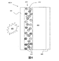
図4は本開示の多数の実施形態に係る耐火複合構造402−4の断面図である。図4に説明される例においては、熱吸収材414が反射コーティング422を含む。反射コーティング422は、数ある反射コーティングの中でも、油性塗料またはエポキシ粉末塗料のような塗料であり得る。反射コーティング422は、例えば、赤外(IR)バンドおよび/または近赤外(NIR)バンドにおいて熱ヒート(thermal heat)を反射し得て、発泡材404を保護する手助けとなり得、そして高い耐火性を持つ複合構造402−4を提供し得る。反射コーティング422としては、数ある反射材料の中でも、金属(例えば、アルミニウムもしくは銀)またはガラスのような反射材料が挙げられ得る。反射コーティング422は、タンブルコーティング(tumble coating)、噴霧塗装、およびロールコーティングを含むがこれらに限定されない様々な処理により熱吸収材414に塗布され得る。熱吸収材(heat adsorption material)414の分離した粒子および離生粒子は、それぞれが反射コーティング422で完全にコーティングされ得る。しかし、実施形態はそのように限定されるわけではない。例えば、熱吸収材(heat adsorption material)414の分離した粒子および離生粒子は、反射コーティング422で一部がコーティングされ得る。
FIG. 4 is a cross-sectional view of a fire resistant composite structure 402-4 according to a number of embodiments of the present disclosure. In the example illustrated in FIG. 4, the
議論されるように、第1面06は熱源20に面するように構成され得る。図4に説明されるように、反射コーティング422を有している熱吸収材414を含むバリア層410が第1面406に隣接して存在し得る。この例においては、熱が熱源420からバリア層410へと伝わり得、ここで熱の一部が熱吸収材414上の反射コーティング422により反射され得る。さらに有利であるのは、例えば、熱源420からまたは(例えば、バリア層410および/もしくは発泡材404の塗布の間の)接着材412の硬化により生じた熱からのいずれかの熱の伝導に反応して、熱吸収材414が早まって溶けてしまわないように、あるいは早まって水を放出してしなわないように、反射コーティング422が熱吸収材414を維持するために役立つことである。
As discussed, the first surface 06 may be configured to face the
図5は本開示の多数の実施形態に係る耐火複合構造の断面図である。図5に示されるように、耐火複合構造502−4は2つ以上のバリア層10、例えば、バリア層310−1を含み得る。ここでは、熱吸収材514は、発泡材504上に反射コーティング522および第2のバリア層510−2を含む。第2のバリアが発泡材504上に、かつ第2面508に隣接して存在し得る。
FIG. 5 is a cross-sectional view of a fire resistant composite structure according to numerous embodiments of the present disclosure. As shown in FIG. 5, the refractory composite structure 502-4 may include more than one barrier layer 10, eg, barrier layer 310-1. Here, the
本開示の多数の実施形態によると、本明細書中で開示されるバリア層10は中空のケイ酸塩材料のようなさらなる構成要素を含み得る。中空のケイ酸塩材料の例として、ガラススフェア、エアロゲル、セノスフェア、ゼオライト、メソ多孔性のケイ酸塩構造、およびこれらの組合せが挙げられるが、これらに限定されるわけではない。エアロゲルは、ゾル−ゲル工程により産生された低密度ケイ酸塩構造を含む。セノスフェアは中空のガラススフェアを含む。中空のガラススフェアは、例えばアルミナのような添加剤を含み得る。ゼオライトは例えば、天然および合成のアルミナ/ケイ酸塩を含み、そして金属陽イオンを含み得る。メソ多孔性のケイ酸塩構造は、有機物の鋳型の周りにシリカを形成させることにより得られる構造を含む。有機物の鋳型はシリカが形成した後に取り除くことができる。 According to numerous embodiments of the present disclosure, the barrier layer 10 disclosed herein may include additional components such as hollow silicate materials. Examples of hollow silicate materials include, but are not limited to, glass spheres, aerogels, cenospheres, zeolites, mesoporous silicate structures, and combinations thereof. Aerogels contain low density silicate structures produced by a sol-gel process. Cenospheres include hollow glass spheres. The hollow glass sphere may contain an additive such as alumina. Zeolites include, for example, natural and synthetic alumina / silicates and can include metal cations. Mesoporous silicate structures include those obtained by forming silica around an organic template. The organic mold can be removed after the silica is formed.
さらなる構成要素は、立方センチメートルあたり1.0グラム(g/cm3)未満である容積密度を有し得る。例えば、さらなる構成要素は、0.5g/cm3未満の容積密度を有し得る。いくつかの用途については、さらなる構成要素は0.2g/cm3未満の容積密度を有し得る。 Additional components can have a volume density that is less than 1.0 grams per cubic centimeter (g / cm 3 ). For example, the further component may have a volume density of less than 0.5 g / cm 3 . For some applications, the additional component may have a volume density of less than 0.2 g / cm 3 .
さらなる構成要素は、バリア層10の1重量%から50重量%までであり得る。1重量%の水から50重量%までの全ての個々の値および部分範囲が本明細書中に含まれ、本明細書中で開示される。例えば、さらなる構成要素は、バリア層10の50重量%、40重量%、または30重量%の上限から、バリア層10の1重量%、2重量%、または3重量%の下限までであり得、ここでは、重量%はバリア層10の総重量に基づく。例えば、さらなる構成要素は、バリア層10の1重量%から50重量%まで、バリア層10の2重量%から40重量%まで、またはバリア層10の3重量%から30重量%までであり得、ここでは、重量%はバリア層10の総重量に基づく。 Further components can be from 1% to 50% by weight of the barrier layer 10. All individual values and subranges from 1 wt% water to 50 wt% are included herein and disclosed herein. For example, the additional component may be from an upper limit of 50%, 40%, or 30% by weight of the barrier layer 10 to a lower limit of 1%, 2%, or 3% by weight of the barrier layer 10; Here, the weight percentage is based on the total weight of the barrier layer 10. For example, the additional component may be 1% to 50% by weight of the barrier layer 10, 2% to 40% by weight of the barrier layer 10, or 3% to 30% by weight of the barrier layer 10, Here, the weight percentage is based on the total weight of the barrier layer 10.
上記は実例において行われており、限定的な例ではない。本開示の様々な実施形態の範囲は、上記を吟味することにより当業者に明らかである他の用途および/または構成要素を含む。 The above is done by way of illustration and not by way of limitation. The scope of the various embodiments of the present disclosure includes other uses and / or components that will be apparent to those skilled in the art upon reviewing the above.
本明細書中で使用される全ての熱吸収材は、特に断りのない限りは、Sigma Aldrich(登録商標)から入手することができる。 All heat absorbing materials used herein can be obtained from Sigma Aldrich® unless otherwise noted.
実施例1〜4
耐火複合構造、実施例1〜4を以下のように組み立てた。熱吸収材と接着材とを十分に混合し、発泡材に塗布し、硬化させて、所望する厚みのバリア層を得た。実施例1〜4については、0.3ミリメートルの厚みの鋼板を、発泡材に対して、実験手順を容易にするために使用したバリア層の構成要素ではない非起泡性ポリウレタン(3M(商標)から入手可能なFoamFast 74)を備えたバリア層の反対側に接着させた。実施例1〜4については、発泡材はポリイソシアヌレート発泡体(The Dow Chemical Companyから入手可能な、VORATHERM(商標)CN604ポリイソシアヌレートシステムを用いて作製されたもの)とした。実施例1〜3については、接着材はエポキシ系(Henkel Corporationから入手可能なLoctite(登録商標)Epoxy Quick Set(商標))とした。実施例4については、接着材は1,000,000の平均分子量を有しているポリスチレン(Sigma Aldrich(登録商標)から入手可能)とした。表1のデータは実施例1〜4の特性を示す。
Examples 1-4
A fire resistant composite structure, Examples 1-4, was assembled as follows. The heat absorbing material and the adhesive were mixed thoroughly, applied to the foam material, and cured to obtain a barrier layer having a desired thickness. For Examples 1-4, a 0.3 millimeter thick steel plate was used as a non-foaming polyurethane (3M ™), which is not a component of the barrier layer used to facilitate the experimental procedure relative to the foam. Adhered to the opposite side of the barrier layer with FoamFast 74) available from. For Examples 1-4, the foam was a polyisocyanurate foam (made using the VORTHERRM ™ CN604 polyisocyanurate system available from The Dow Chemical Company). For Examples 1-3, the adhesive was epoxy based (Loctite® Epoxy Quick Set ™ available from Henkel Corporation). For Example 4, the adhesive was polystyrene (available from Sigma Aldrich®) having an average molecular weight of 1,000,000. The data in Table 1 shows the characteristics of Examples 1-4.

実施例5〜6
耐火複合構造、実施例5〜6を以下のように組み立てた。実施例5については、熱吸収材に、アルミニウム油性塗料(Ace Paintから入手可能なRust Stop油性エナメル塗料225A110 Metallic Aluminium)の反射コーティングをタンブルコーティングした。ここでは、塗料は熱吸収材の総重量に基づいて1から4重量%であった。実施例6については、熱吸収材に、アルミニウムエポキシ粉末塗料(alminium epoxy power paint)(Eastwoodから入手可能なAlminium Powder Coating)の反射コーティングをタンブルコーティングした。反射コーティングを施した熱吸収材それぞれを、それぞれの接着材と混合し、発泡材に塗布し、硬化させて、所望する厚みのバリア層を得た。実施例5〜6については、0.3ミリメートルの厚みの鋼板を、実験手順を容易にするために使用したバリア層の構成要素ではない非起泡性ポリウレタン(3M(商標)から入手可能なFoamFast 74)を備えたバリア層に接着させた。実施例5〜6については、発泡材はポリイソシアヌレート発泡体(The Dow Chemical Companyから入手可能な、VORATHERM(商標)CN604ポリイソシアヌレートシステムを用いて作製されたもの)とした。実施例5〜6については、接着材はエポキシ系(Henkel Corporationから入手可能なLoctite(登録商標)Epoxy Quick Set(商標))とした。表2のデータは実施例5〜6の特性を示す。
Examples 5-6
A fire resistant composite structure, Examples 5-6, was assembled as follows. For Example 5, the heat absorbing material was tumble coated with a reflective coating of aluminum oil paint (Rust Stop oil-based enamel paint 225A110 Metallic Aluminum available from Ace Paint). Here, the paint was 1 to 4% by weight based on the total weight of the heat absorbing material. For Example 6, the heat absorbing material was tumble coated with a reflective coating of aluminum epoxy powder paint (Aluminum Powder Coating available from Eastwood). Each of the heat-absorbing materials provided with the reflective coating was mixed with the respective adhesives, applied to the foam material, and cured to obtain a barrier layer having a desired thickness. For Examples 5-6, a 0.3 millimeter thick steel plate was used as a non-foaming polyurethane (FoamFast available from 3M ™) that is not a component of the barrier layer used to facilitate the experimental procedure. 74). For Examples 5-6, the foam was a polyisocyanurate foam (made using a VOHERHERM ™ CN604 polyisocyanurate system available from The Dow Chemical Company). For Examples 5-6, the adhesive was epoxy-based (Loctite® Epoxy Quick Set ™ available from Henkel Corporation). The data in Table 2 shows the characteristics of Examples 5-6.
実施例7
耐火複合構造、実施例7を以下のように組み立てた。熱吸収材と接着材とを混合し、発泡材に塗布し、硬化させて、所望する厚みのバリア層を得た。実施例7については、0.3ミリメートルの厚みの鋼板を、発泡材に対して、実験手順を容易にするために使用したバリア層の構成要素ではない非起泡性ポリウレタン(3M(商標)から入手可能なFoamFast 74)を備えたバリア層の反対側に接着させた。実施例7については、発泡材は、ポリイソシアヌレート発泡体(The Dow Chemical Companyから入手可能なVORATHERM(商標)CN604ポリイソシアヌレートシステムを用いて作製されたもの)とした。実施例7については、接着材は、5部のEPOXICURE(登録商標)エポキシ樹脂(Buehler,Ltd.から入手可能)と1部のEPOXICURE(登録商標)硬化剤(Buehler Ltd.から入手可能)とを含むエポキシ系とした。表3のデータは実施例7の特性を示す。
Example 7
A fire resistant composite structure, Example 7, was assembled as follows. A heat absorbing material and an adhesive were mixed, applied to a foam material, and cured to obtain a barrier layer having a desired thickness. For Example 7, a 0.3 millimeter thick steel plate was used for the foam material from non-foaming polyurethane (3M ™) that was not a component of the barrier layer used to facilitate the experimental procedure. Adhered to the opposite side of the barrier layer with available FoamFast 74). For Example 7, the foam material was a polyisocyanurate foam (made using a VOHERHERM ™ CN604 polyisocyanurate system available from The Dow Chemical Company). For Example 7, the adhesive comprises 5 parts of EPOXICURE® epoxy resin (available from Buehler, Ltd.) and 1 part of EPOXICURE® curing agent (available from Buehler Ltd.). Including epoxy system. The data in Table 3 shows the characteristics of Example 7.
比較例A〜C
比較例A〜Cを以下のように組み立てた。0.3ミリメートルの厚みの鋼板を、実験手順を容易にするために使用した、比較例A〜Cのいずれについてもバリア層の構成要素ではない非起泡性ポリウレタン(3M(商標)から入手可能なFoamFast 74)を備えたそれぞれのポリイソシアヌレート発泡体(The Dow Chemical Companyから入手可能な、VORATHERM(商標)CN604ポリイソシアヌレートシステムを用いて作製されたもの)に対して接着させた。比較例Aについては、ポリイソシアヌレート発泡体は80ミリメートルの厚みを有していた。比較例Bについては、ポリイソシアヌレート発泡体は100ミリメートルの厚みを有していた。比較例Cについては、ポリイソシアヌレート発泡体は76ミリメートルの厚みを有していた。
Comparative Examples A to C
Comparative Examples A to C were assembled as follows. A 0.3 mm thick steel plate was used to facilitate the experimental procedure and was available from non-foaming polyurethane (3M ™) which is not a constituent of the barrier layer for any of Comparative Examples A to C To each polyisocyanurate foam (made with the VOHERHERM ™ CN604 polyisocyanurate system available from The Dow Chemical Company). For Comparative Example A, the polyisocyanurate foam had a thickness of 80 millimeters. For Comparative Example B, the polyisocyanurate foam had a thickness of 100 millimeters. For Comparative Example C, the polyisocyanurate foam had a thickness of 76 millimeters.
実施例1〜7および比較例A〜Bの耐火性を以下のように試験した。76.2ミリメートル×76.2ミリメートルの穴をThermolyne FD 1535M炉の扉の中で形成した。炉を、EN1361−1試験標準において使用されたものに従う温度対時間曲線が得られるように加熱する。これは、ISO−834−1と同じ加熱曲線である。実施例1〜7および比較例A〜Bのそれぞれを、炉の扉の中の穴に対して各々クランプした。熱電対をそれぞれ、発泡体の表面ならびに/または実施例1〜7および比較例A〜Bのそれぞれについては実験用熱源の反対側である耐火バリアの表面に配置して、温度を記録し、耐火性を決定した。 The fire resistance of Examples 1-7 and Comparative Examples AB was tested as follows. A 76.2 mm x 76.2 mm hole was formed in the door of a Thermolyne FD 1535M furnace. The furnace is heated to obtain a temperature versus time curve according to that used in the EN1361-1 test standard. This is the same heating curve as ISO-834-1. Each of Examples 1-7 and Comparative Examples A-B were each clamped against a hole in the furnace door. Thermocouples are each placed on the surface of the foam and / or the surface of the refractory barrier opposite each of the experimental heat sources for each of Examples 1-7 and Comparative Examples A-B to record the temperature and refractory Sex was determined.
実施例1〜4および実施例7については、バリア層を、実験用熱源に対して発泡材の裏側に配置した。実験の目的のために、実施例1〜4および実施例7には、第2面を含めなかった。実施例5〜6については、バリア層を、実験用熱源に対して発泡材の前面に配置した。実験の目的のために、実施例5〜6には第2面を含めなかった。 For Examples 1-4 and Example 7, the barrier layer was placed on the back side of the foam relative to the experimental heat source. For experimental purposes, Examples 1-4 and Example 7 did not include the second side. For Examples 5-6, the barrier layer was placed on the front face of the foam relative to the experimental heat source. For experimental purposes, Examples 5-6 did not include the second side.
図6Aは実験温度対時間のデータを説明する。プロット650は実施例1について得られたデータを示す。プロット652は実施例2について得られたデータを示す。そして、プロット654は比較例Aについて得られたデータを示す。図6Aのデータは、実施例1〜2のそれぞれについての実験用熱源の反対側にある発泡体および/またはバリア層の表面の温度が、実験が進行した場合、例えば、およそ850秒の時間の後にも、比較例Aについての実験用熱源の反対側にある発泡体および/またはバリア層の表面の温度と比較して、低いままであったことを示す。特に、実施例1〜2のそれぞれについて、実験用熱源の反対側にある発泡体の表面の温度は、少なくとも60分間の期間、140℃を下回ったままであった。実施例1〜2とは対照的に、図6Aのデータは、比較例Aについて、実験用熱源の反対側にある発泡体の表面の温度が60分間の期間の間に170℃に達したことを示している。図6Aのデータは、比較例Aと比較して、実施例1〜2がそれぞれ改善された耐火性を有することを示している。 FIG. 6A illustrates experimental temperature versus time data. Plot 650 shows the data obtained for Example 1. Plot 652 shows the data obtained for Example 2. Plot 654 shows the data obtained for Comparative Example A. The data of FIG. 6A shows that the temperature of the foam and / or barrier layer surface opposite the experimental heat source for each of Examples 1-2, for example, for a time of approximately 850 seconds, as the experiment progressed. Later we show that it remained low compared to the temperature of the foam and / or barrier layer surface on the opposite side of the experimental heat source for Comparative Example A. In particular, for each of Examples 1-2, the temperature of the foam surface on the opposite side of the experimental heat source remained below 140 ° C. for a period of at least 60 minutes. In contrast to Examples 1-2, the data in FIG. 6A shows that for Comparative Example A, the temperature of the foam surface on the opposite side of the experimental heat source reached 170 ° C. during a 60 minute period. Is shown. The data in FIG. 6A shows that Examples 1-2 each have improved fire resistance compared to Comparative Example A.
図6Bは実験温度対時間のデータを説明する。プロット656は実施例3について得られたデータを示す。プロット658は実施例4について得られたデータを示す。そして、プロット660は比較例Bについて得られたデータを示す。図6Bのデータは、実施例3〜4のそれぞれについての実験用熱源の反対側にある発泡体および/またはバリア層の表面の温度が、実験が進行した場合、例えば、およそ1300秒の時間の後にも、比較例Bについての実験用熱源の反対側にある発泡体の表面の温度と比較して、低いままであったことを示している。図6Bのデータは、比較例Bと比較して、実施例3〜4がそれぞれ改善された耐火性を有することを示している。 FIG. 6B illustrates experimental temperature versus time data. Plot 656 shows the data obtained for Example 3. Plot 658 shows the data obtained for Example 4. Plot 660 shows the data obtained for Comparative Example B. The data in FIG. 6B shows that the surface temperature of the foam and / or barrier layer on the opposite side of the experimental heat source for each of Examples 3-4 is, for example, approximately 1300 seconds of time as the experiment progressed. It is also shown later that it remained low compared to the temperature of the foam surface on the opposite side of the experimental heat source for Comparative Example B. The data in FIG. 6B shows that Examples 3-4 each have improved fire resistance compared to Comparative Example B.
図6Cは実験温度対時間のデータを説明する。プロット662は実施例5について得られたデータを示す。そしてプロット664は実施例6について得られたデータを示す。図6Cのデータは、実施例5〜6のそれぞれについての実験用熱源の反対側にある発泡体および/またはバリア層の表面の温度が、少なくとも60分間の期間、140℃を下回ったままであったことを示している。図6Cのデータは、実施例5〜6がそれぞれ、本明細書中に記載されるように耐火性破壊機構を凌ぐ耐火性を有することを示している。 FIG. 6C illustrates experimental temperature versus time data. Plot 662 shows the data obtained for Example 5. Plot 664 shows the data obtained for Example 6. The data in FIG. 6C indicated that the surface temperature of the foam and / or barrier layer opposite the experimental heat source for each of Examples 5-6 remained below 140 ° C. for a period of at least 60 minutes. It is shown that. The data in FIG. 6C shows that Examples 5-6 each have a fire resistance that surpasses the fire-resistant fracture mechanism as described herein.
図6Dは実験温度対時間のデータを説明する。プロット668は実施例7について得られたデータを示す。そして、プロット670は比較例Cについて得られたデータを示す。図6Dのデータは、実施例7についての実験用熱源と反対側にある発泡体の表面の温度が、実験が進行した場合、例えば、およそ475秒の時間の後にも、比較例Cについての実験用熱源の反対側にある発泡体および/またはバリア層の表面の温度と比較して、低いままであったことを示している。図6Dのデータは、実施例7が比較例Cと比較して改善された耐火性を有することを示している。 FIG. 6D illustrates experimental temperature versus time data. Plot 668 shows the data obtained for Example 7. Plot 670 shows the data obtained for Comparative Example C. The data in FIG. 6D shows that the temperature on the surface of the foam opposite the experimental heat source for Example 7 is the experiment for Comparative Example C, even after a time of approximately 475 seconds, for example, as the experiment progressed. It shows that it remained low compared to the temperature of the surface of the foam and / or barrier layer on the opposite side of the heat source. The data in FIG. 6D shows that Example 7 has improved fire resistance compared to Comparative Example C.
Claims (20)
前記発泡材上のバリア層
を備える耐火複合構造であって、
前記バリア層が接着材および熱吸収材を含み、前記熱吸収材が40℃から140℃の融点を有し、前記バリア層の15重量%から99重量%である、
耐火複合構造。 A fireproof composite structure comprising a foam material between a first surface and a second surface; and a barrier layer on the foam material,
The barrier layer includes an adhesive and a heat absorbing material, the heat absorbing material has a melting point of 40 ° C. to 140 ° C., and is 15% to 99% by weight of the barrier layer;
Fireproof composite structure.
前記発泡材上のバリア層
を備える耐火複合構造であって、
前記バリア層が接着材および熱吸収材を含み、前記熱吸収材が反射コーティング、40℃から140℃の融点を有し、前記バリア層の15重量%から99重量%である、
耐火複合構造。 A fireproof composite structure comprising a foam material between a first surface and a second surface; and a barrier layer on the foam material,
The barrier layer comprises an adhesive and a heat absorbing material, the heat absorbing material is a reflective coating, has a melting point of 40 ° C. to 140 ° C., and is 15% to 99% by weight of the barrier layer;
Fireproof composite structure.
20. The structure according to any one of claims 13 to 19, comprising a second barrier layer on the foam material and adjacent to the second surface, wherein the second barrier layer is a second adhesive material. And a second heat absorbing material, wherein the second heat absorbing material has a melting point of 40 ° C. to 140 ° C. and is 15% to 99% by weight of the second barrier layer.
Applications Claiming Priority (1)
| Application Number | Priority Date | Filing Date | Title |
|---|---|---|---|
| PCT/IT2011/000418 WO2013098859A1 (en) | 2011-12-27 | 2011-12-27 | Fire resistant composite structure |
Publications (1)
| Publication Number | Publication Date |
|---|---|
| JP2015507562A true JP2015507562A (en) | 2015-03-12 |
Family
ID=45755453
Family Applications (1)
| Application Number | Title | Priority Date | Filing Date |
|---|---|---|---|
| JP2014549640A Pending JP2015507562A (en) | 2011-12-27 | 2011-12-27 | Fireproof composite structure |
Country Status (9)
| Country | Link |
|---|---|
| US (1) | US20140329079A1 (en) |
| EP (1) | EP2797739A1 (en) |
| JP (1) | JP2015507562A (en) |
| KR (1) | KR20140111260A (en) |
| CN (1) | CN104023966A (en) |
| BR (1) | BR112014015822A8 (en) |
| IN (1) | IN2014CN04783A (en) |
| MX (1) | MX2014007939A (en) |
| WO (1) | WO2013098859A1 (en) |
Cited By (1)
| Publication number | Priority date | Publication date | Assignee | Title |
|---|---|---|---|---|
| JP7401140B2 (en) | 2022-02-28 | 2023-12-19 | 中建材科創新技術研究院(山東)有限公司 | Airgel composite thermal insulation fireproof board and its manufacturing process |
Families Citing this family (26)
| Publication number | Priority date | Publication date | Assignee | Title |
|---|---|---|---|---|
| EP2777926A1 (en) | 2013-03-14 | 2014-09-17 | Dow Global Technologies LLC | Panel with fire barrier |
| TR201904049T4 (en) | 2014-04-18 | 2019-04-22 | Dow Global Technologies Llc | Fire barrier panel. |
| TW201623566A (en) * | 2014-11-03 | 2016-07-01 | 漢高智慧財產控股公司 | Compositions having a matrix and a hydrated salt of an acid and a group I or II element of the periodic table dispersed therein, and electronic devices assembled therewith |
| GB201420766D0 (en) | 2014-11-21 | 2015-01-07 | Bpb United Kingdom Ltd | Fire resistant calcium sulphate-based products |
| GB201420768D0 (en) | 2014-11-21 | 2015-01-07 | Bpb United Kingdom Ltd | Calcium sulphate-based products |
| GB201420767D0 (en) | 2014-11-21 | 2015-01-07 | Bpb United Kingdom Ltd | Fire resistant calcium sulphate-based products |
| US10655939B1 (en) * | 2016-02-10 | 2020-05-19 | Consolidate Nuclear Security, LLC | Thermal protection barrier for delaying access |
| US11400688B1 (en) * | 2016-02-10 | 2022-08-02 | Consolidated Nuclear Security, LLC | Thermal protection barrier |
| EP3363959B1 (en) * | 2017-02-17 | 2019-07-24 | Schillings GmbH & Co. KG | Fire resistant coating |
| ES2945720T3 (en) | 2017-11-28 | 2023-07-06 | Dow Global Technologies Llc | insulation boxes |
| US11486135B2 (en) | 2017-11-28 | 2022-11-01 | Dow Global Technologies Llc | Glass fiber-reinforced polyurethane/polyisocyanurate foam insulation board |
| EP3717243A4 (en) | 2017-11-28 | 2021-04-28 | Dow Global Technologies LLC | Polyurethane-based insulation board |
| US11395931B2 (en) | 2017-12-02 | 2022-07-26 | Mighty Fire Breaker Llc | Method of and system network for managing the application of fire and smoke inhibiting compositions on ground surfaces before the incidence of wild-fires, and also thereafter, upon smoldering ambers and ashes to reduce smoke and suppress fire re-ignition |
| US10430757B2 (en) | 2017-12-02 | 2019-10-01 | N-Fire Suppression, Inc. | Mass timber building factory system for producing prefabricated class-A fire-protected mass timber building components for use in constructing prefabricated class-A fire-protected mass timber buildings |
| US10814150B2 (en) | 2017-12-02 | 2020-10-27 | M-Fire Holdings Llc | Methods of and system networks for wireless management of GPS-tracked spraying systems deployed to spray property and ground surfaces with environmentally-clean wildfire inhibitor to protect and defend against wildfires |
| US10332222B1 (en) | 2017-12-02 | 2019-06-25 | M-Fire Supression, Inc. | Just-in-time factory methods, system and network for prefabricating class-A fire-protected wood-framed buildings and components used to construct the same |
| US10290004B1 (en) | 2017-12-02 | 2019-05-14 | M-Fire Suppression, Inc. | Supply chain management system for supplying clean fire inhibiting chemical (CFIC) totes to a network of wood-treating lumber and prefabrication panel factories and wood-framed building construction job sites |
| US11836807B2 (en) | 2017-12-02 | 2023-12-05 | Mighty Fire Breaker Llc | System, network and methods for estimating and recording quantities of carbon securely stored in class-A fire-protected wood-framed and mass-timber buildings on construction job-sites, and class-A fire-protected wood-framed and mass timber components in factory environments |
| US10653904B2 (en) | 2017-12-02 | 2020-05-19 | M-Fire Holdings, Llc | Methods of suppressing wild fires raging across regions of land in the direction of prevailing winds by forming anti-fire (AF) chemical fire-breaking systems using environmentally clean anti-fire (AF) liquid spray applied using GPS-tracking techniques |
| US10260232B1 (en) | 2017-12-02 | 2019-04-16 | M-Fire Supression, Inc. | Methods of designing and constructing Class-A fire-protected multi-story wood-framed buildings |
| US10311444B1 (en) | 2017-12-02 | 2019-06-04 | M-Fire Suppression, Inc. | Method of providing class-A fire-protection to wood-framed buildings using on-site spraying of clean fire inhibiting chemical liquid on exposed interior wood surfaces of the wood-framed buildings, and mobile computing systems for uploading fire-protection certifications and status information to a central database and remote access thereof by firefighters on job site locations during fire outbreaks on construction sites |
| US11865390B2 (en) | 2017-12-03 | 2024-01-09 | Mighty Fire Breaker Llc | Environmentally-clean water-based fire inhibiting biochemical compositions, and methods of and apparatus for applying the same to protect property against wildfire |
| US11865394B2 (en) | 2017-12-03 | 2024-01-09 | Mighty Fire Breaker Llc | Environmentally-clean biodegradable water-based concentrates for producing fire inhibiting and fire extinguishing liquids for fighting class A and class B fires |
| US11826592B2 (en) | 2018-01-09 | 2023-11-28 | Mighty Fire Breaker Llc | Process of forming strategic chemical-type wildfire breaks on ground surfaces to proactively prevent fire ignition and flame spread, and reduce the production of smoke in the presence of a wild fire |
| CN109180893B (en) * | 2018-08-14 | 2020-10-09 | 山东科技大学 | Low-calorific-value high-strength polyurethane material for coal mine grouting and preparation method thereof |
| US11911643B2 (en) | 2021-02-04 | 2024-02-27 | Mighty Fire Breaker Llc | Environmentally-clean fire inhibiting and extinguishing compositions and products for sorbing flammable liquids while inhibiting ignition and extinguishing fire |
Citations (7)
| Publication number | Priority date | Publication date | Assignee | Title |
|---|---|---|---|---|
| JPS54107934A (en) * | 1978-01-09 | 1979-08-24 | Stahl Joel S | Refractory* heat insulating layer |
| JPH0988204A (en) * | 1995-09-22 | 1997-03-31 | Sekisui Chem Co Ltd | Flame-retardant sound-insulating sheet |
| JPH09217441A (en) * | 1996-02-09 | 1997-08-19 | Itoki Co Ltd | Fire resistive panel |
| JPH10169317A (en) * | 1996-12-12 | 1998-06-23 | Riboole:Kk | Fireproof storage box for floppy disk |
| JP2000104366A (en) * | 1998-07-29 | 2000-04-11 | Sekisui Chem Co Ltd | Fire resistant component |
| JP2003201790A (en) * | 2002-01-08 | 2003-07-18 | Eiko Yamada:Kk | Fireproof safe for electronic storage medium |
| JP2006160858A (en) * | 2004-12-06 | 2006-06-22 | Kaneka Corp | Flame-retardant coated synthetic resin foam |
Family Cites Families (9)
| Publication number | Priority date | Publication date | Assignee | Title |
|---|---|---|---|---|
| GB1477658A (en) * | 1974-10-08 | 1977-06-22 | Ici Ltd | Laminates |
| US4303736A (en) * | 1979-07-20 | 1981-12-01 | Leonard Torobin | Hollow plastic microspheres |
| US4596682A (en) * | 1984-05-11 | 1986-06-24 | Benjamin Mosier | Method of manufacturing fire retardant polystyrene insulating board |
| CH687970A5 (en) * | 1993-03-26 | 1997-04-15 | Alusuisse Lonza Services Ag | Composite panels with two outer layers and a core. |
| EP1314753B1 (en) * | 2001-11-24 | 2006-12-27 | Prometheus Developments Ltd. | Fire retardant composition |
| JP2006506486A (en) * | 2002-11-13 | 2006-02-23 | ジェイジェイアイ エルエルシー | Thermoplastic or thermosetting refractory composition containing intumescent specialty chemicals |
| US7571758B2 (en) * | 2004-01-10 | 2009-08-11 | Barbara Hildegard Pause | Building conditioning technique using phase change materials in the roof structure |
| US20090235599A1 (en) * | 2008-03-18 | 2009-09-24 | Maximilian Ware | Laminated structural insulated panel with perforated foam core and method of making same |
| US20110262704A1 (en) * | 2010-04-21 | 2011-10-27 | Moshe Rock | Flame resistant composite fabrics |
-
2011
- 2011-12-27 CN CN201180076061.0A patent/CN104023966A/en active Pending
- 2011-12-27 MX MX2014007939A patent/MX2014007939A/en unknown
- 2011-12-27 IN IN4783CHN2014 patent/IN2014CN04783A/en unknown
- 2011-12-27 EP EP11820821.4A patent/EP2797739A1/en not_active Withdrawn
- 2011-12-27 KR KR1020147017297A patent/KR20140111260A/en not_active Application Discontinuation
- 2011-12-27 JP JP2014549640A patent/JP2015507562A/en active Pending
- 2011-12-27 US US14/366,023 patent/US20140329079A1/en not_active Abandoned
- 2011-12-27 BR BR112014015822A patent/BR112014015822A8/en not_active IP Right Cessation
- 2011-12-27 WO PCT/IT2011/000418 patent/WO2013098859A1/en active Application Filing
Patent Citations (7)
| Publication number | Priority date | Publication date | Assignee | Title |
|---|---|---|---|---|
| JPS54107934A (en) * | 1978-01-09 | 1979-08-24 | Stahl Joel S | Refractory* heat insulating layer |
| JPH0988204A (en) * | 1995-09-22 | 1997-03-31 | Sekisui Chem Co Ltd | Flame-retardant sound-insulating sheet |
| JPH09217441A (en) * | 1996-02-09 | 1997-08-19 | Itoki Co Ltd | Fire resistive panel |
| JPH10169317A (en) * | 1996-12-12 | 1998-06-23 | Riboole:Kk | Fireproof storage box for floppy disk |
| JP2000104366A (en) * | 1998-07-29 | 2000-04-11 | Sekisui Chem Co Ltd | Fire resistant component |
| JP2003201790A (en) * | 2002-01-08 | 2003-07-18 | Eiko Yamada:Kk | Fireproof safe for electronic storage medium |
| JP2006160858A (en) * | 2004-12-06 | 2006-06-22 | Kaneka Corp | Flame-retardant coated synthetic resin foam |
Cited By (1)
| Publication number | Priority date | Publication date | Assignee | Title |
|---|---|---|---|---|
| JP7401140B2 (en) | 2022-02-28 | 2023-12-19 | 中建材科創新技術研究院(山東)有限公司 | Airgel composite thermal insulation fireproof board and its manufacturing process |
Also Published As
| Publication number | Publication date |
|---|---|
| IN2014CN04783A (en) | 2015-09-18 |
| WO2013098859A1 (en) | 2013-07-04 |
| BR112014015822A8 (en) | 2017-07-04 |
| EP2797739A1 (en) | 2014-11-05 |
| US20140329079A1 (en) | 2014-11-06 |
| CN104023966A (en) | 2014-09-03 |
| KR20140111260A (en) | 2014-09-18 |
| MX2014007939A (en) | 2014-07-30 |
| BR112014015822A2 (en) | 2017-06-13 |
Similar Documents
| Publication | Publication Date | Title |
|---|---|---|
| JP2015507562A (en) | Fireproof composite structure | |
| CN106170388B (en) | Partition with fire barrier | |
| US20170067248A1 (en) | Panel with fire barrier | |
| AU2004247667B2 (en) | Multi-layer fire-barrier systems | |
| MXPA06010475A (en) | Thermal insulation composite with improved thermal stability and improved fire resistance. | |
| EP2830875B1 (en) | Fire resistant composite structure | |
| JP2014534097A5 (en) | ||
| JP2007113386A (en) | Method of manufacturing compound heat insulating panel and compound foaming panel | |
| US11834376B2 (en) | Method for producing fireproof materials based on sodium silicate | |
| EP2831013A2 (en) | Geopolymer precursor-aerogel compositions | |
| KR20170042437A (en) | Reinforced hybrid insulating material and production method thereof | |
| JP2013253382A (en) | Manufacturing method of noncombustible heat insulation panel | |
| JP7425435B2 (en) | laminate | |
| CN108977106A (en) | A kind of integrated thermal-insulation film and preparation method thereof | |
| KR100795768B1 (en) | Fire resistant insulated building panels utilizing intumescent coatings | |
| JPH09228507A (en) | Composite heat insulative panel | |
| KR100953127B1 (en) | Method for manufacturing interior and exterior material using phenol resin | |
| CN218535893U (en) | Composite material and shell, battery cell monomer, battery module and battery pack using same | |
| JPH1136473A (en) | Heat-insulating, fire-resisting sheet | |
| JPS625315Y2 (en) | ||
| WO2023239306A1 (en) | Intumescent sheet used in an electric vehicle battery for thermal runaway management | |
| KR101821591B1 (en) | expanded polystylene which have flammmable capability | |
| JP2020094205A (en) | Heat storage material and manufacturing method of heat storage material | |
| JP6545015B2 (en) | Laminate | |
| JP2022126907A (en) | Coating structure and forming method thereof |
Legal Events
| Date | Code | Title | Description |
|---|---|---|---|
| A977 | Report on retrieval |
Free format text: JAPANESE INTERMEDIATE CODE: A971007 Effective date: 20151106 |
|
| A131 | Notification of reasons for refusal |
Free format text: JAPANESE INTERMEDIATE CODE: A131 Effective date: 20151117 |
|
| A131 | Notification of reasons for refusal |
Free format text: JAPANESE INTERMEDIATE CODE: A131 Effective date: 20160419 |
|
| A521 | Request for written amendment filed |
Free format text: JAPANESE INTERMEDIATE CODE: A523 Effective date: 20160715 |
|
| A131 | Notification of reasons for refusal |
Free format text: JAPANESE INTERMEDIATE CODE: A131 Effective date: 20160913 |
|
| A521 | Request for written amendment filed |
Free format text: JAPANESE INTERMEDIATE CODE: A523 Effective date: 20161202 |
|
| A131 | Notification of reasons for refusal |
Free format text: JAPANESE INTERMEDIATE CODE: A131 Effective date: 20170221 |
|
| A02 | Decision of refusal |
Free format text: JAPANESE INTERMEDIATE CODE: A02 Effective date: 20170926 |