JP2015507533A - Method for producing hydrogen separation composite membrane - Google Patents
Method for producing hydrogen separation composite membrane Download PDFInfo
- Publication number
- JP2015507533A JP2015507533A JP2014549169A JP2014549169A JP2015507533A JP 2015507533 A JP2015507533 A JP 2015507533A JP 2014549169 A JP2014549169 A JP 2014549169A JP 2014549169 A JP2014549169 A JP 2014549169A JP 2015507533 A JP2015507533 A JP 2015507533A
- Authority
- JP
- Japan
- Prior art keywords
- carrier
- particulate material
- gas
- coat
- particle size
- Prior art date
- Legal status (The legal status is an assumption and is not a legal conclusion. Google has not performed a legal analysis and makes no representation as to the accuracy of the status listed.)
- Pending
Links
- 238000000926 separation method Methods 0.000 title claims abstract description 49
- 229910052739 hydrogen Inorganic materials 0.000 title claims description 39
- 239000001257 hydrogen Substances 0.000 title claims description 39
- 239000012528 membrane Substances 0.000 title abstract description 88
- 238000004519 manufacturing process Methods 0.000 title abstract description 30
- 239000002131 composite material Substances 0.000 title description 6
- 125000004435 hydrogen atom Chemical class [H]* 0.000 title description 2
- 238000000034 method Methods 0.000 claims abstract description 99
- 239000011236 particulate material Substances 0.000 claims abstract description 98
- 230000003746 surface roughness Effects 0.000 claims abstract description 64
- 239000000463 material Substances 0.000 claims abstract description 57
- 239000011148 porous material Substances 0.000 claims abstract description 43
- 239000007789 gas Substances 0.000 claims description 163
- 239000002245 particle Substances 0.000 claims description 106
- 238000000137 annealing Methods 0.000 claims description 44
- UFHFLCQGNIYNRP-UHFFFAOYSA-N Hydrogen Chemical compound [H][H] UFHFLCQGNIYNRP-UHFFFAOYSA-N 0.000 claims description 34
- 229910052751 metal Inorganic materials 0.000 claims description 33
- 239000002184 metal Substances 0.000 claims description 33
- 238000000151 deposition Methods 0.000 claims description 22
- 229910000510 noble metal Inorganic materials 0.000 claims description 15
- 102000002322 Egg Proteins Human genes 0.000 claims description 10
- 108010000912 Egg Proteins Proteins 0.000 claims description 10
- 239000003054 catalyst Substances 0.000 claims description 10
- 210000003278 egg shell Anatomy 0.000 claims description 10
- 229910052809 inorganic oxide Inorganic materials 0.000 claims description 7
- 239000003870 refractory metal Substances 0.000 claims description 7
- 238000001035 drying Methods 0.000 claims description 2
- 239000010408 film Substances 0.000 abstract description 24
- 238000005336 cracking Methods 0.000 abstract description 12
- 239000010409 thin film Substances 0.000 abstract description 8
- KDLHZDBZIXYQEI-UHFFFAOYSA-N Palladium Chemical compound [Pd] KDLHZDBZIXYQEI-UHFFFAOYSA-N 0.000 description 56
- 238000007747 plating Methods 0.000 description 41
- 229910052763 palladium Inorganic materials 0.000 description 30
- 238000009792 diffusion process Methods 0.000 description 24
- 238000007772 electroless plating Methods 0.000 description 21
- 230000004888 barrier function Effects 0.000 description 20
- 239000000243 solution Substances 0.000 description 19
- 239000000758 substrate Substances 0.000 description 19
- 238000006243 chemical reaction Methods 0.000 description 16
- 230000008569 process Effects 0.000 description 16
- 238000009826 distribution Methods 0.000 description 15
- 230000008021 deposition Effects 0.000 description 14
- IJGRMHOSHXDMSA-UHFFFAOYSA-N Atomic nitrogen Chemical compound N#N IJGRMHOSHXDMSA-UHFFFAOYSA-N 0.000 description 13
- 229910045601 alloy Inorganic materials 0.000 description 13
- 239000000956 alloy Substances 0.000 description 13
- 239000007788 liquid Substances 0.000 description 12
- 238000005498 polishing Methods 0.000 description 9
- CURLTUGMZLYLDI-UHFFFAOYSA-N Carbon dioxide Chemical compound O=C=O CURLTUGMZLYLDI-UHFFFAOYSA-N 0.000 description 8
- 230000006835 compression Effects 0.000 description 8
- 238000007906 compression Methods 0.000 description 8
- XLYOFNOQVPJJNP-UHFFFAOYSA-N water Substances O XLYOFNOQVPJJNP-UHFFFAOYSA-N 0.000 description 8
- 239000011261 inert gas Substances 0.000 description 7
- 229910021645 metal ion Inorganic materials 0.000 description 7
- 239000000203 mixture Substances 0.000 description 7
- 229910052757 nitrogen Inorganic materials 0.000 description 7
- PXHVJJICTQNCMI-UHFFFAOYSA-N Nickel Chemical compound [Ni] PXHVJJICTQNCMI-UHFFFAOYSA-N 0.000 description 6
- 238000010438 heat treatment Methods 0.000 description 6
- 239000002002 slurry Substances 0.000 description 6
- 239000012298 atmosphere Substances 0.000 description 5
- 230000008901 benefit Effects 0.000 description 5
- 239000000969 carrier Substances 0.000 description 5
- 230000006870 function Effects 0.000 description 5
- 238000000227 grinding Methods 0.000 description 5
- 150000002431 hydrogen Chemical class 0.000 description 5
- 150000002739 metals Chemical class 0.000 description 5
- 230000003287 optical effect Effects 0.000 description 5
- -1 palladium hydride Chemical class 0.000 description 5
- 230000035699 permeability Effects 0.000 description 5
- 229910052709 silver Inorganic materials 0.000 description 5
- 239000010935 stainless steel Substances 0.000 description 5
- 229910001220 stainless steel Inorganic materials 0.000 description 5
- XKRFYHLGVUSROY-UHFFFAOYSA-N Argon Chemical compound [Ar] XKRFYHLGVUSROY-UHFFFAOYSA-N 0.000 description 4
- MCMNRKCIXSYSNV-UHFFFAOYSA-N Zirconium dioxide Chemical compound O=[Zr]=O MCMNRKCIXSYSNV-UHFFFAOYSA-N 0.000 description 4
- 239000001569 carbon dioxide Substances 0.000 description 4
- 229910002092 carbon dioxide Inorganic materials 0.000 description 4
- 239000011248 coating agent Substances 0.000 description 4
- 238000000576 coating method Methods 0.000 description 4
- PCHJSUWPFVWCPO-UHFFFAOYSA-N gold Chemical compound [Au] PCHJSUWPFVWCPO-UHFFFAOYSA-N 0.000 description 4
- 229910052737 gold Inorganic materials 0.000 description 4
- 239000010931 gold Substances 0.000 description 4
- 239000007769 metal material Substances 0.000 description 4
- VNWKTOKETHGBQD-UHFFFAOYSA-N methane Chemical compound C VNWKTOKETHGBQD-UHFFFAOYSA-N 0.000 description 4
- 238000010899 nucleation Methods 0.000 description 4
- BASFCYQUMIYNBI-UHFFFAOYSA-N platinum Chemical compound [Pt] BASFCYQUMIYNBI-UHFFFAOYSA-N 0.000 description 4
- 230000009467 reduction Effects 0.000 description 4
- 238000011160 research Methods 0.000 description 4
- 235000019592 roughness Nutrition 0.000 description 4
- 239000004332 silver Substances 0.000 description 4
- 238000012360 testing method Methods 0.000 description 4
- VYZAMTAEIAYCRO-UHFFFAOYSA-N Chromium Chemical compound [Cr] VYZAMTAEIAYCRO-UHFFFAOYSA-N 0.000 description 3
- ZOKXTWBITQBERF-UHFFFAOYSA-N Molybdenum Chemical compound [Mo] ZOKXTWBITQBERF-UHFFFAOYSA-N 0.000 description 3
- 230000015572 biosynthetic process Effects 0.000 description 3
- 229910052804 chromium Inorganic materials 0.000 description 3
- 239000011651 chromium Substances 0.000 description 3
- 230000006872 improvement Effects 0.000 description 3
- 229910001026 inconel Inorganic materials 0.000 description 3
- 229910001092 metal group alloy Inorganic materials 0.000 description 3
- 229910052750 molybdenum Inorganic materials 0.000 description 3
- 239000011733 molybdenum Substances 0.000 description 3
- 229910052759 nickel Inorganic materials 0.000 description 3
- 238000002203 pretreatment Methods 0.000 description 3
- 238000012545 processing Methods 0.000 description 3
- 230000007420 reactivation Effects 0.000 description 3
- 239000007787 solid Substances 0.000 description 3
- UGFAIRIUMAVXCW-UHFFFAOYSA-N Carbon monoxide Chemical compound [O+]#[C-] UGFAIRIUMAVXCW-UHFFFAOYSA-N 0.000 description 2
- KCXVZYZYPLLWCC-UHFFFAOYSA-N EDTA Chemical compound OC(=O)CN(CC(O)=O)CCN(CC(O)=O)CC(O)=O KCXVZYZYPLLWCC-UHFFFAOYSA-N 0.000 description 2
- PIICEJLVQHRZGT-UHFFFAOYSA-N Ethylenediamine Chemical compound NCCN PIICEJLVQHRZGT-UHFFFAOYSA-N 0.000 description 2
- OAKJQQAXSVQMHS-UHFFFAOYSA-N Hydrazine Chemical compound NN OAKJQQAXSVQMHS-UHFFFAOYSA-N 0.000 description 2
- XEEYBQQBJWHFJM-UHFFFAOYSA-N Iron Chemical compound [Fe] XEEYBQQBJWHFJM-UHFFFAOYSA-N 0.000 description 2
- KJTLSVCANCCWHF-UHFFFAOYSA-N Ruthenium Chemical compound [Ru] KJTLSVCANCCWHF-UHFFFAOYSA-N 0.000 description 2
- VYPSYNLAJGMNEJ-UHFFFAOYSA-N Silicium dioxide Chemical compound O=[Si]=O VYPSYNLAJGMNEJ-UHFFFAOYSA-N 0.000 description 2
- BQCADISMDOOEFD-UHFFFAOYSA-N Silver Chemical compound [Ag] BQCADISMDOOEFD-UHFFFAOYSA-N 0.000 description 2
- GWEVSGVZZGPLCZ-UHFFFAOYSA-N Titan oxide Chemical compound O=[Ti]=O GWEVSGVZZGPLCZ-UHFFFAOYSA-N 0.000 description 2
- QCWXUUIWCKQGHC-UHFFFAOYSA-N Zirconium Chemical compound [Zr] QCWXUUIWCKQGHC-UHFFFAOYSA-N 0.000 description 2
- 230000002378 acidificating effect Effects 0.000 description 2
- PNEYBMLMFCGWSK-UHFFFAOYSA-N aluminium oxide Inorganic materials [O-2].[O-2].[O-2].[Al+3].[Al+3] PNEYBMLMFCGWSK-UHFFFAOYSA-N 0.000 description 2
- 238000013459 approach Methods 0.000 description 2
- 229910052786 argon Inorganic materials 0.000 description 2
- 229910002091 carbon monoxide Inorganic materials 0.000 description 2
- 230000008859 change Effects 0.000 description 2
- 239000003638 chemical reducing agent Substances 0.000 description 2
- 239000013078 crystal Substances 0.000 description 2
- 238000009713 electroplating Methods 0.000 description 2
- 238000011049 filling Methods 0.000 description 2
- 239000010419 fine particle Substances 0.000 description 2
- 229910000856 hastalloy Inorganic materials 0.000 description 2
- 239000001307 helium Substances 0.000 description 2
- 229910052734 helium Inorganic materials 0.000 description 2
- SWQJXJOGLNCZEY-UHFFFAOYSA-N helium atom Chemical compound [He] SWQJXJOGLNCZEY-UHFFFAOYSA-N 0.000 description 2
- 229930195733 hydrocarbon Natural products 0.000 description 2
- 150000002430 hydrocarbons Chemical class 0.000 description 2
- 230000001788 irregular Effects 0.000 description 2
- 238000005259 measurement Methods 0.000 description 2
- 239000002105 nanoparticle Substances 0.000 description 2
- 229910052754 neon Inorganic materials 0.000 description 2
- GKAOGPIIYCISHV-UHFFFAOYSA-N neon atom Chemical compound [Ne] GKAOGPIIYCISHV-UHFFFAOYSA-N 0.000 description 2
- 239000010955 niobium Substances 0.000 description 2
- 229910052758 niobium Inorganic materials 0.000 description 2
- GUCVJGMIXFAOAE-UHFFFAOYSA-N niobium atom Chemical compound [Nb] GUCVJGMIXFAOAE-UHFFFAOYSA-N 0.000 description 2
- 229910052697 platinum Inorganic materials 0.000 description 2
- 230000035484 reaction time Effects 0.000 description 2
- 238000006479 redox reaction Methods 0.000 description 2
- 238000002407 reforming Methods 0.000 description 2
- 229910052702 rhenium Inorganic materials 0.000 description 2
- WUAPFZMCVAUBPE-UHFFFAOYSA-N rhenium atom Chemical compound [Re] WUAPFZMCVAUBPE-UHFFFAOYSA-N 0.000 description 2
- 229910052707 ruthenium Inorganic materials 0.000 description 2
- 239000000725 suspension Substances 0.000 description 2
- WFKWXMTUELFFGS-UHFFFAOYSA-N tungsten Chemical compound [W] WFKWXMTUELFFGS-UHFFFAOYSA-N 0.000 description 2
- 229910052721 tungsten Inorganic materials 0.000 description 2
- 239000010937 tungsten Substances 0.000 description 2
- 229910052726 zirconium Inorganic materials 0.000 description 2
- 229910001316 Ag alloy Inorganic materials 0.000 description 1
- 239000004215 Carbon black (E152) Substances 0.000 description 1
- RYGMFSIKBFXOCR-UHFFFAOYSA-N Copper Chemical compound [Cu] RYGMFSIKBFXOCR-UHFFFAOYSA-N 0.000 description 1
- 229910001252 Pd alloy Inorganic materials 0.000 description 1
- 101150003085 Pdcl gene Proteins 0.000 description 1
- XUIMIQQOPSSXEZ-UHFFFAOYSA-N Silicon Chemical compound [Si] XUIMIQQOPSSXEZ-UHFFFAOYSA-N 0.000 description 1
- RTAQQCXQSZGOHL-UHFFFAOYSA-N Titanium Chemical compound [Ti] RTAQQCXQSZGOHL-UHFFFAOYSA-N 0.000 description 1
- WGLPBDUCMAPZCE-UHFFFAOYSA-N Trioxochromium Chemical compound O=[Cr](=O)=O WGLPBDUCMAPZCE-UHFFFAOYSA-N 0.000 description 1
- 230000003213 activating effect Effects 0.000 description 1
- 230000004913 activation Effects 0.000 description 1
- 229910002065 alloy metal Inorganic materials 0.000 description 1
- 229910052782 aluminium Inorganic materials 0.000 description 1
- XAGFODPZIPBFFR-UHFFFAOYSA-N aluminium Chemical compound [Al] XAGFODPZIPBFFR-UHFFFAOYSA-N 0.000 description 1
- 239000007864 aqueous solution Substances 0.000 description 1
- 125000004429 atom Chemical group 0.000 description 1
- QVGXLLKOCUKJST-UHFFFAOYSA-N atomic oxygen Chemical compound [O] QVGXLLKOCUKJST-UHFFFAOYSA-N 0.000 description 1
- 230000009286 beneficial effect Effects 0.000 description 1
- WVMHLYQJPRXKLC-UHFFFAOYSA-N borane;n,n-dimethylmethanamine Chemical compound B.CN(C)C WVMHLYQJPRXKLC-UHFFFAOYSA-N 0.000 description 1
- 238000006555 catalytic reaction Methods 0.000 description 1
- 229910010293 ceramic material Inorganic materials 0.000 description 1
- CETPSERCERDGAM-UHFFFAOYSA-N ceric oxide Chemical compound O=[Ce]=O CETPSERCERDGAM-UHFFFAOYSA-N 0.000 description 1
- 229910000422 cerium(IV) oxide Inorganic materials 0.000 description 1
- 238000005229 chemical vapour deposition Methods 0.000 description 1
- 229910000423 chromium oxide Inorganic materials 0.000 description 1
- 238000004140 cleaning Methods 0.000 description 1
- 229910017052 cobalt Inorganic materials 0.000 description 1
- 239000010941 cobalt Substances 0.000 description 1
- GUTLYIVDDKVIGB-UHFFFAOYSA-N cobalt atom Chemical compound [Co] GUTLYIVDDKVIGB-UHFFFAOYSA-N 0.000 description 1
- 239000008139 complexing agent Substances 0.000 description 1
- 229910052802 copper Inorganic materials 0.000 description 1
- 239000010949 copper Substances 0.000 description 1
- 230000003247 decreasing effect Effects 0.000 description 1
- 230000007547 defect Effects 0.000 description 1
- 230000032798 delamination Effects 0.000 description 1
- 230000001419 dependent effect Effects 0.000 description 1
- 238000001514 detection method Methods 0.000 description 1
- 238000011161 development Methods 0.000 description 1
- 230000000694 effects Effects 0.000 description 1
- 238000000313 electron-beam-induced deposition Methods 0.000 description 1
- 239000000446 fuel Substances 0.000 description 1
- 238000009499 grossing Methods 0.000 description 1
- 229910052735 hafnium Inorganic materials 0.000 description 1
- VBJZVLUMGGDVMO-UHFFFAOYSA-N hafnium atom Chemical compound [Hf] VBJZVLUMGGDVMO-UHFFFAOYSA-N 0.000 description 1
- 229910052738 indium Inorganic materials 0.000 description 1
- APFVFJFRJDLVQX-UHFFFAOYSA-N indium atom Chemical compound [In] APFVFJFRJDLVQX-UHFFFAOYSA-N 0.000 description 1
- 238000003842 industrial chemical process Methods 0.000 description 1
- 238000007737 ion beam deposition Methods 0.000 description 1
- 229910052741 iridium Inorganic materials 0.000 description 1
- GKOZUEZYRPOHIO-UHFFFAOYSA-N iridium atom Chemical compound [Ir] GKOZUEZYRPOHIO-UHFFFAOYSA-N 0.000 description 1
- 229910052742 iron Inorganic materials 0.000 description 1
- WPBNNNQJVZRUHP-UHFFFAOYSA-L manganese(2+);methyl n-[[2-(methoxycarbonylcarbamothioylamino)phenyl]carbamothioyl]carbamate;n-[2-(sulfidocarbothioylamino)ethyl]carbamodithioate Chemical compound [Mn+2].[S-]C(=S)NCCNC([S-])=S.COC(=O)NC(=S)NC1=CC=CC=C1NC(=S)NC(=O)OC WPBNNNQJVZRUHP-UHFFFAOYSA-L 0.000 description 1
- 230000007246 mechanism Effects 0.000 description 1
- 230000008018 melting Effects 0.000 description 1
- 238000002844 melting Methods 0.000 description 1
- 239000002923 metal particle Substances 0.000 description 1
- 238000001465 metallisation Methods 0.000 description 1
- QJGQUHMNIGDVPM-UHFFFAOYSA-N nitrogen group Chemical group [N] QJGQUHMNIGDVPM-UHFFFAOYSA-N 0.000 description 1
- 230000006911 nucleation Effects 0.000 description 1
- 229910052762 osmium Inorganic materials 0.000 description 1
- SYQBFIAQOQZEGI-UHFFFAOYSA-N osmium atom Chemical compound [Os] SYQBFIAQOQZEGI-UHFFFAOYSA-N 0.000 description 1
- 239000001301 oxygen Substances 0.000 description 1
- 229910052760 oxygen Inorganic materials 0.000 description 1
- 150000002940 palladium Chemical class 0.000 description 1
- PIBWKRNGBLPSSY-UHFFFAOYSA-L palladium(II) chloride Chemical compound Cl[Pd]Cl PIBWKRNGBLPSSY-UHFFFAOYSA-L 0.000 description 1
- 239000013618 particulate matter Substances 0.000 description 1
- 239000006072 paste Substances 0.000 description 1
- 230000008092 positive effect Effects 0.000 description 1
- 239000000843 powder Substances 0.000 description 1
- 239000010970 precious metal Substances 0.000 description 1
- 238000003825 pressing Methods 0.000 description 1
- 238000000746 purification Methods 0.000 description 1
- 238000011084 recovery Methods 0.000 description 1
- 239000010948 rhodium Substances 0.000 description 1
- 229910052703 rhodium Inorganic materials 0.000 description 1
- MHOVAHRLVXNVSD-UHFFFAOYSA-N rhodium atom Chemical compound [Rh] MHOVAHRLVXNVSD-UHFFFAOYSA-N 0.000 description 1
- 229910052710 silicon Inorganic materials 0.000 description 1
- 239000010703 silicon Substances 0.000 description 1
- 239000000377 silicon dioxide Substances 0.000 description 1
- 238000009718 spray deposition Methods 0.000 description 1
- 238000005118 spray pyrolysis Methods 0.000 description 1
- 238000004544 sputter deposition Methods 0.000 description 1
- 239000003381 stabilizer Substances 0.000 description 1
- 238000000629 steam reforming Methods 0.000 description 1
- 229910052715 tantalum Inorganic materials 0.000 description 1
- GUVRBAGPIYLISA-UHFFFAOYSA-N tantalum atom Chemical compound [Ta] GUVRBAGPIYLISA-UHFFFAOYSA-N 0.000 description 1
- 238000005496 tempering Methods 0.000 description 1
- 238000002207 thermal evaporation Methods 0.000 description 1
- AXZWODMDQAVCJE-UHFFFAOYSA-L tin(II) chloride (anhydrous) Chemical compound [Cl-].[Cl-].[Sn+2] AXZWODMDQAVCJE-UHFFFAOYSA-L 0.000 description 1
- 229910052719 titanium Inorganic materials 0.000 description 1
- 239000010936 titanium Substances 0.000 description 1
- 238000012876 topography Methods 0.000 description 1
- 229910052720 vanadium Inorganic materials 0.000 description 1
- LEONUFNNVUYDNQ-UHFFFAOYSA-N vanadium atom Chemical compound [V] LEONUFNNVUYDNQ-UHFFFAOYSA-N 0.000 description 1
- 238000005406 washing Methods 0.000 description 1
- 229910001233 yttria-stabilized zirconia Inorganic materials 0.000 description 1
- 239000010457 zeolite Substances 0.000 description 1
Images


Classifications
-
- B—PERFORMING OPERATIONS; TRANSPORTING
- B01—PHYSICAL OR CHEMICAL PROCESSES OR APPARATUS IN GENERAL
- B01D—SEPARATION
- B01D53/00—Separation of gases or vapours; Recovering vapours of volatile solvents from gases; Chemical or biological purification of waste gases, e.g. engine exhaust gases, smoke, fumes, flue gases, aerosols
- B01D53/22—Separation of gases or vapours; Recovering vapours of volatile solvents from gases; Chemical or biological purification of waste gases, e.g. engine exhaust gases, smoke, fumes, flue gases, aerosols by diffusion
- B01D53/228—Separation of gases or vapours; Recovering vapours of volatile solvents from gases; Chemical or biological purification of waste gases, e.g. engine exhaust gases, smoke, fumes, flue gases, aerosols by diffusion characterised by specific membranes
-
- B—PERFORMING OPERATIONS; TRANSPORTING
- B01—PHYSICAL OR CHEMICAL PROCESSES OR APPARATUS IN GENERAL
- B01D—SEPARATION
- B01D69/00—Semi-permeable membranes for separation processes or apparatus characterised by their form, structure or properties; Manufacturing processes specially adapted therefor
- B01D69/10—Supported membranes; Membrane supports
- B01D69/108—Inorganic support material
-
- B—PERFORMING OPERATIONS; TRANSPORTING
- B01—PHYSICAL OR CHEMICAL PROCESSES OR APPARATUS IN GENERAL
- B01D—SEPARATION
- B01D67/00—Processes specially adapted for manufacturing semi-permeable membranes for separation processes or apparatus
- B01D67/0039—Inorganic membrane manufacture
-
- B—PERFORMING OPERATIONS; TRANSPORTING
- B01—PHYSICAL OR CHEMICAL PROCESSES OR APPARATUS IN GENERAL
- B01D—SEPARATION
- B01D67/00—Processes specially adapted for manufacturing semi-permeable membranes for separation processes or apparatus
- B01D67/0039—Inorganic membrane manufacture
- B01D67/0046—Inorganic membrane manufacture by slurry techniques, e.g. die or slip-casting
-
- B—PERFORMING OPERATIONS; TRANSPORTING
- B01—PHYSICAL OR CHEMICAL PROCESSES OR APPARATUS IN GENERAL
- B01D—SEPARATION
- B01D67/00—Processes specially adapted for manufacturing semi-permeable membranes for separation processes or apparatus
- B01D67/0039—Inorganic membrane manufacture
- B01D67/0069—Inorganic membrane manufacture by deposition from the liquid phase, e.g. electrochemical deposition
-
- B—PERFORMING OPERATIONS; TRANSPORTING
- B01—PHYSICAL OR CHEMICAL PROCESSES OR APPARATUS IN GENERAL
- B01D—SEPARATION
- B01D67/00—Processes specially adapted for manufacturing semi-permeable membranes for separation processes or apparatus
- B01D67/0039—Inorganic membrane manufacture
- B01D67/0076—Pretreatment of inorganic membrane material prior to membrane formation, e.g. coating of metal powder
-
- B—PERFORMING OPERATIONS; TRANSPORTING
- B01—PHYSICAL OR CHEMICAL PROCESSES OR APPARATUS IN GENERAL
- B01D—SEPARATION
- B01D67/00—Processes specially adapted for manufacturing semi-permeable membranes for separation processes or apparatus
- B01D67/0081—After-treatment of organic or inorganic membranes
- B01D67/0095—Drying
-
- B—PERFORMING OPERATIONS; TRANSPORTING
- B01—PHYSICAL OR CHEMICAL PROCESSES OR APPARATUS IN GENERAL
- B01D—SEPARATION
- B01D69/00—Semi-permeable membranes for separation processes or apparatus characterised by their form, structure or properties; Manufacturing processes specially adapted therefor
- B01D69/02—Semi-permeable membranes for separation processes or apparatus characterised by their form, structure or properties; Manufacturing processes specially adapted therefor characterised by their properties
-
- B—PERFORMING OPERATIONS; TRANSPORTING
- B01—PHYSICAL OR CHEMICAL PROCESSES OR APPARATUS IN GENERAL
- B01D—SEPARATION
- B01D69/00—Semi-permeable membranes for separation processes or apparatus characterised by their form, structure or properties; Manufacturing processes specially adapted therefor
- B01D69/10—Supported membranes; Membrane supports
-
- B—PERFORMING OPERATIONS; TRANSPORTING
- B01—PHYSICAL OR CHEMICAL PROCESSES OR APPARATUS IN GENERAL
- B01D—SEPARATION
- B01D69/00—Semi-permeable membranes for separation processes or apparatus characterised by their form, structure or properties; Manufacturing processes specially adapted therefor
- B01D69/12—Composite membranes; Ultra-thin membranes
- B01D69/1213—Laminated layers
-
- B—PERFORMING OPERATIONS; TRANSPORTING
- B01—PHYSICAL OR CHEMICAL PROCESSES OR APPARATUS IN GENERAL
- B01D—SEPARATION
- B01D71/00—Semi-permeable membranes for separation processes or apparatus characterised by the material; Manufacturing processes specially adapted therefor
- B01D71/02—Inorganic material
- B01D71/022—Metals
- B01D71/0223—Group 8, 9 or 10 metals
- B01D71/02231—Palladium
-
- C—CHEMISTRY; METALLURGY
- C01—INORGANIC CHEMISTRY
- C01B—NON-METALLIC ELEMENTS; COMPOUNDS THEREOF; METALLOIDS OR COMPOUNDS THEREOF NOT COVERED BY SUBCLASS C01C
- C01B3/00—Hydrogen; Gaseous mixtures containing hydrogen; Separation of hydrogen from mixtures containing it; Purification of hydrogen
- C01B3/50—Separation of hydrogen or hydrogen containing gases from gaseous mixtures, e.g. purification
- C01B3/501—Separation of hydrogen or hydrogen containing gases from gaseous mixtures, e.g. purification by diffusion
- C01B3/503—Separation of hydrogen or hydrogen containing gases from gaseous mixtures, e.g. purification by diffusion characterised by the membrane
-
- B—PERFORMING OPERATIONS; TRANSPORTING
- B01—PHYSICAL OR CHEMICAL PROCESSES OR APPARATUS IN GENERAL
- B01D—SEPARATION
- B01D2256/00—Main component in the product gas stream after treatment
- B01D2256/16—Hydrogen
-
- B—PERFORMING OPERATIONS; TRANSPORTING
- B01—PHYSICAL OR CHEMICAL PROCESSES OR APPARATUS IN GENERAL
- B01D—SEPARATION
- B01D2323/00—Details relating to membrane preparation
- B01D2323/08—Specific temperatures applied
-
- B—PERFORMING OPERATIONS; TRANSPORTING
- B01—PHYSICAL OR CHEMICAL PROCESSES OR APPARATUS IN GENERAL
- B01D—SEPARATION
- B01D2323/00—Details relating to membrane preparation
- B01D2323/08—Specific temperatures applied
- B01D2323/081—Heating
-
- B—PERFORMING OPERATIONS; TRANSPORTING
- B01—PHYSICAL OR CHEMICAL PROCESSES OR APPARATUS IN GENERAL
- B01D—SEPARATION
- B01D2323/00—Details relating to membrane preparation
- B01D2323/10—Specific pressure applied
-
- B—PERFORMING OPERATIONS; TRANSPORTING
- B01—PHYSICAL OR CHEMICAL PROCESSES OR APPARATUS IN GENERAL
- B01D—SEPARATION
- B01D2325/00—Details relating to properties of membranes
- B01D2325/02—Details relating to pores or porosity of the membranes
- B01D2325/0283—Pore size
-
- B—PERFORMING OPERATIONS; TRANSPORTING
- B01—PHYSICAL OR CHEMICAL PROCESSES OR APPARATUS IN GENERAL
- B01D—SEPARATION
- B01D2325/00—Details relating to properties of membranes
- B01D2325/06—Surface irregularities
-
- B—PERFORMING OPERATIONS; TRANSPORTING
- B01—PHYSICAL OR CHEMICAL PROCESSES OR APPARATUS IN GENERAL
- B01D—SEPARATION
- B01D2325/00—Details relating to properties of membranes
- B01D2325/22—Thermal or heat-resistance properties
Abstract
ガス分離システムを作製する方法が記載される。該方法は、(1)初期平均孔径および初期表面粗さを有する多孔性担体を提供するステップ、ならびに(2)(a)担体の平均孔径を機能的に縮小するためにおよび(b)担体の測定可能な表面粗さを機能的に低減するために、微粒子材料を多孔性担体の第1の表面に適用するステップを含む。サイズが小さくなる微粒子材料の追加の膜を適用して、平均孔径をさらに縮小させ、担体の粗さを低下させる。担体が所望のレベルの平滑性に達したら、これの上にガス選択性材料の薄膜を付着させる。膜および担体を次に、商業使用中の膜の亀裂発生を防止または実質的に低減する条件下でアニーリングする。A method of making a gas separation system is described. The method includes (1) providing a porous support having an initial average pore size and initial surface roughness, and (2) (a) functionally reducing the average pore size of the support and (b) Applying the particulate material to the first surface of the porous support to functionally reduce the measurable surface roughness. An additional film of particulate material with reduced size is applied to further reduce the average pore size and reduce the roughness of the support. When the support has reached the desired level of smoothness, a thin film of gas selective material is deposited thereon. The membrane and support are then annealed under conditions that prevent or substantially reduce cracking of the membrane during commercial use.
Description
本発明は、ガス分離システムを作製する方法に関するものである。特に本発明は、混合ガス流から水素ガスを分離するのに特に好適であるガス分離システムを作製する方法に関するものである。 The present invention relates to a method of making a gas separation system. In particular, the present invention relates to a method of making a gas separation system that is particularly suitable for separating hydrogen gas from a mixed gas stream.
多くの工業用途のために、安価な精製ガス源が必要とされている。水素はこのようなガスの一例である。安価な精製水素源は、多くの工業的化学工程、および燃料電池電力システムにおけるエネルギーの生産において需要がある。同様に安価な水素精製方法によって炭化水素改質、改質反応装置および水性ガスシフト反応の適用可能性を著しく拡張することができる。安価な精製水素への要求に応えるために、水素および他のガスを含有する各種の工業ガス流からの水素の選択的回収に使用できるより効果的な水素透過性ガス分離膜システムを開発するために、かなりの研究が行われてきた。 For many industrial applications, an inexpensive source of purified gas is needed. Hydrogen is an example of such a gas. Inexpensive purified hydrogen sources are in demand in many industrial chemical processes and in the production of energy in fuel cell power systems. Similarly, inexpensive hydrogen purification methods can significantly extend the applicability of hydrocarbon reforming, reforming reactors and water gas shift reactions. To develop a more effective hydrogen permeable gas separation membrane system that can be used for the selective recovery of hydrogen from various industrial gas streams containing hydrogen and other gases to meet the demand for inexpensive purified hydrogen Considerable research has been conducted.
貴金属薄膜を利用するガス分離システムは当分野で公知である。特に、パラジウム膜を含むシステムは、これの高い水素透過性およびこれの理論的に無限の水素選択性のために、広く研究されてきた。パラジウムガス分離膜は、幾つかの取得済みの特許および公開済み特許出願の主題である。 Gas separation systems that utilize noble metal thin films are known in the art. In particular, systems containing palladium membranes have been extensively studied due to their high hydrogen permeability and their theoretically infinite hydrogen selectivity. Palladium gas separation membranes are the subject of several patents and published patent applications.
パラジウム膜で遭遇する1つの問題は、膜の使用中および/または製造中の亀裂発生である。パラジウム膜の亀裂により、望ましくないガスが膜を通過して、生成物ガス流が汚染される。膜の亀裂発生には考えられる幾つかの原因があり得るが、膜製造中のアニーリング条件が亀裂発生に寄与すると考えられる。 One problem encountered with palladium membranes is cracking during use and / or manufacturing of the membrane. Cracks in the palladium membrane cause undesirable gases to pass through the membrane and contaminate the product gas stream. There are several possible causes for film cracking, but it is believed that annealing conditions during film manufacture contribute to cracking.
ガス分離システムの公知の製造工程において、1つ以上の貴金属(例えばパラジウム)薄層を、ある程度の前処理がなされた、またはなされていない多孔性担体に付着させる。複合システム(担体および金属膜)は次にアニーリングされて(即ち特定の条件下で高温にて保持される。)、個々の構成要素の溶融および焼戻しを助ける。このような1つのアニーリング処理は、Ma et al.のU.S.Patent 7,727,596で論じられ、新たに形成されたパラジウム含有膜を水素の存在下で250℃までの温度および8バールまでの範囲に及ぶ圧力にてアニーリングすることを含む。このような条件でアニーリングされた膜は、使用中の亀裂発生が認められている。亀裂発生は、少なくとも一部は、膜中のパラジウムヒドリドのアルファ形およびベータ形の両方が存在するためと思われる。アルファ形およびベータ形は、異なる結晶サイズを有する。 In known manufacturing processes for gas separation systems, one or more thin layers of noble metal (eg, palladium) are deposited on a porous support that has been or has not undergone some pretreatment. The composite system (support and metal film) is then annealed (ie, held at high temperature under certain conditions) to aid melting and tempering of the individual components. One such annealing process is described in Ma et al. U. S. Patent 7,727,596, including annealing a newly formed palladium-containing membrane in the presence of hydrogen at temperatures up to 250 ° C. and pressures ranging up to 8 bar. The film annealed under such conditions has been observed to crack during use. Cracking appears to be due at least in part to the presence of both alpha and beta forms of palladium hydride in the film. The alpha and beta forms have different crystal sizes.
コストは、ガス分離システム、とりわけパラジウムベースのシステムの研究の常に推進力であり得るもう1つの問題である。貴金属ベースのガス分離システムは、製造するのに費用がかかる。従って、製造効率を改善する当分野におけるいずれの改善も、きわめて貴重であり得て、システム製造者はこのような改善を見出すためにかなりの資源を投じている。 Cost is another issue that can always be a driving force in the research of gas separation systems, especially palladium-based systems. Precious metal based gas separation systems are expensive to manufacture. Thus, any improvement in the field that improves manufacturing efficiency can be invaluable, and system manufacturers have invested considerable resources to find such improvements.
要するに、公知の製造方法によって生産されたシステムに見られる機能上の問題(例えば膜の亀裂発生)の幾つかを低減または排除するガス分離システムを作成する方法に対する要求がある。加えて、公知の方法よりも経済上より効率的な(例えば必要なパラジウムがより少ない、またはメッキステップが少ない。)製造方法に対する要求がある。 In short, there is a need for a method of creating a gas separation system that reduces or eliminates some of the functional problems (eg, film cracking) found in systems produced by known manufacturing methods. In addition, there is a need for a manufacturing method that is more economically efficient than known methods (eg, requires less palladium or requires fewer plating steps).
しかし、機能を犠牲にして製造効率を向上させることはできない。多くの用途では、ガス生成物の純度が最も重要であり、ガス分離システム製造における手抜きによって工業的需要を満たせないシステムが生じることが多い。従って製造者は、効率と機能との間で適正なバランスを見出す必要がある。このことは工程改善への全体的なアプローチをしばしば必要とする。言い換えれば、製造方法の一つの側面を変更することによって、効率の向上がもたらされることがあるが、この変更と下流での他の変更を組合せることは、全体の製造効率および生成物の性能を何倍にもするものとして作用することがある。本発明の基礎をなす研究は、このような全体的なアプローチに基づいている。 However, manufacturing efficiency cannot be improved at the expense of function. In many applications, the purity of the gas product is paramount, and cuts in gas separation system manufacturing often result in systems that cannot meet industrial demands. Therefore, manufacturers need to find the right balance between efficiency and function. This often requires an overall approach to process improvement. In other words, changing one aspect of the manufacturing process may result in improved efficiency, but combining this change with other changes downstream will result in overall manufacturing efficiency and product performance. It may act as something that doubles. The research underlying the present invention is based on such an overall approach.
第1の平均孔径を有する多孔性金属担体を提供することを含む、ガス分離システムを作製する方法が提供される。多孔性担体は第1の表面および第2の表面を有し、各前記表面は他方の表面と対向して、担体の厚さを画成する。「第1の表面」は、この用語が本明細書で使用される場合、ガス分離材料の薄膜および該第1の表面と該薄膜との間に位置するいずれの中間拡散バリアも最終的に担持する多孔性担体の表面を意味する。 A method of making a gas separation system is provided that includes providing a porous metal support having a first average pore size. The porous carrier has a first surface and a second surface, each said surface facing the other surface and defining the thickness of the carrier. “First surface”, as the term is used herein, ultimately carries a thin film of gas separation material and any intermediate diffusion barrier located between the first surface and the thin film. Means the surface of the porous carrier.
方法は、担体の第1の表面を、第1の平均粒径を有する第1の微粒子材料と接触させてコート担体上に第1のコート表面を形成し、次にいずれの過剰な第1の微粒子材料をも第1のコート表面から除去することを含む。 The method contacts a first surface of a carrier with a first particulate material having a first average particle size to form a first coated surface on the coated carrier, and then any excess first Also removing the particulate material from the first coat surface.
方法はさらに、第1のコート表面を第1の平均粒径より小さい第2の平均粒径を有する第2の微粒子材料と接触させてコート担体上に第2のコート表面を形成し、続いて第2のコート表面から過剰な第2の微粒子材料を除去することを含む。 The method further includes contacting the first coated surface with a second particulate material having a second average particle size smaller than the first average particle size to form a second coated surface on the coated carrier, followed by Removing excess second particulate material from the second coat surface.
方法は付着ステップおよびアニーリングステップも含む。付着ステップにおいて、コートされた第1の表面および間に位置するいずれの微粒子状物質をも覆うように、ガス選択性材料の少なくとも1つの層が付着される。アニーリングステップにおいて、コート担体およびこれの上に付着したガス選択性材料を、ガス選択性材料の粒子成長を促進する温度にてアニーリングする。 The method also includes an attachment step and an annealing step. In the deposition step, at least one layer of gas selective material is deposited so as to cover the coated first surface and any particulate matter located therebetween. In the annealing step, the coat carrier and the gas selective material deposited thereon are annealed at a temperature that promotes particle growth of the gas selective material.
多孔性金属担体であって、第1の表面および第2の表面を有し、各表面が互いに対向して担体の厚さを画成する担体を提供するステップを含む、ガス分離システムを作製する方法も提供される。担体の第1の表面は、測定可能な初期表面粗さおよび初期平均孔径を有する。担体の第1の表面は次に、初期平均孔径より小さい第1の平均粒径を有する第1の微粒子材料と接触して、コート担体上に第1のコート表面を形成する。過剰な第1の微粒子材料は第1のコート表面から除去される。 Producing a gas separation system comprising providing a porous metal carrier having a first surface and a second surface, each surface facing each other and defining the thickness of the carrier. A method is also provided. The first surface of the support has a measurable initial surface roughness and initial average pore size. The first surface of the carrier is then contacted with a first particulate material having a first average particle size that is smaller than the initial average pore size to form a first coated surface on the coated carrier. Excess first particulate material is removed from the first coat surface.
方法は、第1のコート表面を第1の平均粒径より小さい第2の平均粒径を第2の微粒子材料と接触させてコート担体上に第2のコート表面を形成するステップをさらに含む。過剰な第2の微粒子材料は次に、第2のコート表面から除去される。 The method further includes contacting the first coated surface with a second average particle size that is smaller than the first average particle size with the second particulate material to form a second coated surface on the coated carrier. Excess second particulate material is then removed from the second coat surface.
方法は、前記第2のコート担体を第2の平均粒径より小さい第3の平均粒径を有する第3の微粒子材料と接触させて、第3のコート表面を形成するステップをさらに含み、第3のコート表面の測定された表面粗さは、第1のコート表面の測定された表面粗さよりも小さい。 The method further includes contacting the second coat carrier with a third particulate material having a third average particle size smaller than the second average particle size to form a third coat surface, The measured surface roughness of the 3 coat surface is less than the measured surface roughness of the first coat surface.
以下の記述において、説明の目的で本発明の1つ以上の実施形態の理解を提供するために、多数の詳細事項、例えば例示的な濃度および代替的ステップまたは手順について述べる。しかし、これらの具体的な詳細事項が本発明を実施するために必要でないことは当業者には明らかである。 In the following description, numerous details are set forth such as exemplary concentrations and alternative steps or procedures in order to provide an understanding of one or more embodiments of the invention for purposes of illustration. However, it will be apparent to one skilled in the art that these specific details are not required in order to practice the invention.
さらに以下の詳細な記述は、本発明を実施するための現在考えられる最良の形態のものである。記述は限定的な意味を意図するものではなく、発明の一般原理を説明するためになされるにすぎない。本発明の多様な特徴および利点は、以下の詳細な記述を参照することによって、よりただちに理解され得る。 Further, the following detailed description is of the best presently contemplated mode for carrying out the invention. The description is not intended to be limiting and is only made to illustrate the general principles of the invention. The various features and advantages of the present invention may be more readily understood by reference to the following detailed description.
最初の事項として、および読者への助けとなるように、複数の用語を定義し、ガス分離システムのごく一般的な記述を行う。 As a first matter and to help the reader, define a number of terms and give a very general description of the gas separation system.
概して、ガス分離システムは、薄手金属フィルムおよび/または他の材料の連続層が表面に付着して、液体および特定のガスに対して不透過性の複合膜を形成するガス透過性多孔性担体よりなる。1つ以上の中間構造、例えば中間拡散バリアが金属フィルムと担体との間に存在することがあり、システムの性能を向上させる。 In general, a gas separation system is more than a gas permeable porous carrier in which a continuous layer of thin metal film and / or other material adheres to the surface to form a composite membrane that is impermeable to liquids and certain gases. Become. One or more intermediate structures, such as an intermediate diffusion barrier, may be present between the metal film and the carrier, improving system performance.
本明細書で使用する場合、「覆う(overlie)」および「下位の(underlie)」という用語は、装置またはシステムの1つの要素の別の要素に対する相対的関係を記述するために使用する用語である。どちらの用語も、装置またはシステムの1つの要素が別の要素に隣接しているが、中間要素によって隔離されていることを意味すると解釈できる。例えば、膜は多孔性担体の第1の表面を覆うことができ、同時に膜と第1の表面との間に挟まれた中間拡散バリアを有する。さらに、担体を「上下反対に」または「表を上にして」保持することによって、「覆う」および「下位の」の意味は変わらない。 As used herein, the terms “overlie” and “underly” are terms used to describe the relative relationship of one element of a device or system to another element. is there. Both terms can be interpreted to mean that one element of the device or system is adjacent to another element but is isolated by an intermediate element. For example, the membrane can cover the first surface of the porous carrier and at the same time has an intermediate diffusion barrier sandwiched between the membrane and the first surface. Further, by holding the carrier “upside down” or “face up”, the meanings of “cover” and “lower” do not change.
「液密」という用語は、本明細書で使用する場合、製造中のガス分離膜システムに適用される説明用語である。「液密」という用語は、膜および膜が上に載っている担体の厚さにわたる圧力差の印加時に、液体(通例は水)が膜の孔をもはや通過できないような密度にガス分離膜が達していることを意味する。多くの例において、例えば約760mmHgまでの大気圧より低い圧力差の印加時に、水が膜を通過しない場合、膜は「液密」であると考えられる。 The term “liquid tight” as used herein is an explanatory term applied to a gas separation membrane system being manufactured. The term “liquid tight” refers to a gas separation membrane that has a density such that liquid (typically water) can no longer pass through the pores of the membrane upon application of a pressure differential across the thickness of the membrane and the carrier on which the membrane rests. It means that it has reached. In many instances, a membrane is considered “liquid-tight” if no water passes through the membrane upon application of a pressure difference below atmospheric, for example up to about 760 mmHg.
「ガス選択性材料」は、本明細書で使用する用語として、高密度の薄手フィルムの形である場合にガスに対して選択透過性であり、このためこのような材料の高密度薄層が選択したガスを選択的に通過させて、他のガスの通過を防止するように機能する材料である。該用語は、ガス選択性金属、特に貴金属を含む。 “Gas-selective material” as used herein is selectively permeable to gas when in the form of a dense thin film, so that a dense thin layer of such material is present. It is a material that functions to selectively pass selected gases and prevent the passage of other gases. The term includes gas selective metals, especially noble metals.
「ガスタイト」または「ガス密」という用語は、本明細書で使用する場合、製造中のガス分離膜システムに適用される説明用語である。「ガスタイト」または「ガス密」という用語は、本明細書で使用する場合、膜が特定のガスを透過させるが、他のガスがある場合でも、膜をほとんど通過させないことを意味する。このため膜は、特定のガスに対して高い「選択性」を有する。多くの例において、特定のガスは水素である。 The terms “gas tight” or “gas tight”, as used herein, are descriptive terms that apply to a gas separation membrane system being manufactured. The terms “gas tight” or “gas tight” as used herein means that the membrane is permeable to certain gases, but hardly passes through the membrane even in the presence of other gases. For this reason, the membrane has a high “selectivity” for a specific gas. In many instances, the particular gas is hydrogen.
「選択性」という用語は、本明細書で使用する場合、膜を通る漏れ検知ガス、例えば窒素またはヘリウムの流量で割った膜を通る特定のガスの流量の無次元の比によって表される、膜または膜システムの測定された属性である。「流量」という用語は、本明細書で使用する場合、所与の圧力にてガスが膜を通過できる速度を意味する。流量の測定に使用される次元は、使用する測定装置に応じて変わることがある。通例、流量はm3/(m2時バール)として測定される。高純度の水素を製造する場合、理想的なガス選択性膜は無限に近づく選択性を有するが、実際には、膜の窒素に対する選択性は通常、100から1,000の範囲である。 The term “selectivity” as used herein is represented by a dimensionless ratio of the flow rate of a particular gas through a membrane divided by the flow rate of a leak detection gas, eg, nitrogen or helium, through the membrane, A measured attribute of a membrane or membrane system. The term “flow rate” as used herein means the rate at which a gas can pass through a membrane at a given pressure. The dimensions used to measure the flow rate may vary depending on the measurement device used. Typically, the flow rate is measured as m 3 / (m 2 bar). When producing high purity hydrogen, an ideal gas-selective membrane has an infinite selectivity, but in practice the selectivity of the membrane to nitrogen is typically in the range of 100 to 1,000.
「安定性」という用語は、ガス選択性膜に関して使用する場合、合理的に苛酷な高温高圧条件下であっても、膜が長期間にわたるガス混合物からの特定のガス(例えば水素)の分離に使用され、漏れを生じ得ないことを意味する。このため、高安定性膜は、膜の使用中に膜の選択性の低下率が合理的に低い。 The term “stability”, when used with respect to gas-selective membranes, allows separation of a particular gas (eg, hydrogen) from a gas mixture over an extended period of time, even under reasonably severe high temperature and pressure conditions. Used to mean that it can not leak. For this reason, highly stable membranes have a reasonably low rate of decrease in membrane selectivity during use of the membrane.
ガス分離システムの製造において遭遇する多様な表面の粗さ、特に中間拡散バリアとして利用される多孔性担体の粗さは、本発明の重要な一態様である。出願人は、金属付着前の多孔性担体の測定可能な表面粗さの低減により、製造工程の効率および生じるガス分離システムの性能の改善が提供されると判断している。 The various surface roughness encountered in the manufacture of gas separation systems, particularly the roughness of porous supports utilized as intermediate diffusion barriers, is an important aspect of the present invention. Applicants have determined that reducing measurable surface roughness of the porous support prior to metal deposition provides improved manufacturing process efficiency and resulting gas separation system performance.
表面の粗さは、当業者に公知の方法または手段のいずれをも使用することによって測定または決定され得る。表面の粗さを定量するために表面プロファイルを測定する装置手段の一例は、プロフィロメータである。ナノビア(登録商標)によって市販されているST400光学プロフィロメータとして知られる、光学プロフィロメータなど、いずれの市販のプロフィロメータも使用できる。この装置を使用して、あるユーザ定義された表面の表面形態およびトポグラフィーを測定、分析および定量することができる。 Surface roughness can be measured or determined by using any method or means known to those skilled in the art. An example of a device means for measuring the surface profile to quantify the surface roughness is a profilometer. Any commercially available profilometer can be used, such as the optical profilometer known as the ST400 optical profilometer marketed by Nanovia®. This device can be used to measure, analyze and quantify the surface morphology and topography of certain user-defined surfaces.
表面粗さを定義するために使用され得る粗さパラメータとしては、平均表面粗さまたは算術平均高さ(Sa)、二乗平均高さまたはRMS表面粗さ(Sq)、高さ分布の歪度(Ssk)、高さ分布の尖度(Sku)、最大ピーク高さ(Sp)、最大谷深さとも呼ばれる最大ピット高さ(Sv)および最大高さ(Sv)などのパラメータが挙げられる。これらの粗さパラメータは、表面の粗さおよび他の特徴の測定およびキャラクタリゼーションの分野の当業者に周知である。これらの特定のパラメータは表面を、平均線からの表面の粗さプロファイルの垂直方向の偏差に基づいてキャラクタリゼーションする。 Roughness parameters that can be used to define the surface roughness include average surface roughness or arithmetic average height (Sa), root mean square or RMS surface roughness (Sq), skewness of height distribution ( Ssk), kurtosis of height distribution (Sku), maximum peak height (Sp), parameters such as maximum pit height (Sv) and maximum height (Sv), also called maximum valley depth. These roughness parameters are well known to those skilled in the art of measuring and characterizing surface roughness and other features. These particular parameters characterize the surface based on the vertical deviation of the surface roughness profile from the average line.
ここで本発明による方法に転じると、本発明は、ガス分離膜を作製する方法およびこれの使用に関する。より詳細には、本発明は、少なくとも1つのガス選択性材料のきわめて薄い膜層を有するガス分離システムを製造する経済的に有利な方法、このような製造方法によって生じたガス分離膜システムおよびこれの使用に関するものである。 Turning now to the method according to the invention, the invention relates to a method of making a gas separation membrane and its use. More particularly, the present invention relates to an economically advantageous method for producing a gas separation system having a very thin membrane layer of at least one gas-selective material, a gas separation membrane system produced by such a production method, and this Is about the use of.
非常に広い意味では、請求される発明は、(1)多孔性金属担体を微粒子材料によって連続的に処理またはコーティングして表面粗さおよび機能性平均孔径を低減するステップ、(2)金属薄膜をコート多孔性基材に付着させるステップならびに(3)商業使用中の膜の亀裂発生を低減または排除する条件下で、基材および膜をアニーリングするステップを含む、ガス分離システムを作製する方法である。 In a very broad sense, the claimed invention includes (1) a step of continuously treating or coating a porous metal support with a particulate material to reduce surface roughness and functional average pore size; (2) a metal thin film A method of making a gas separation system comprising: attaching to a coated porous substrate; and (3) annealing the substrate and membrane under conditions that reduce or eliminate cracking of the membrane during commercial use. .
本発明による方法は、多孔性担体の提供から開始する。本発明のガス分離膜システムの作製で使用される多孔性担体またはこれのいずれの要素も、ガス透過性(例えば水素透過性)であり、上に付着されるガス選択性材料の(複数の)膜の担体として使用するのに好適である、いずれの多孔性材料をも含み得る。多孔性担体は、多孔性材料が(以下で論じる。)金属間拡散バリア粒子の膜およびガス選択性材料の膜の多孔性材料への適用を可能にする表面を有するならば、いずれの形状または形態でもよい。このような形状は、多孔性材料の平面または曲線状シートを含み得る。好ましくは、多孔性担体は、相互に対向して担体の厚さを画成する、第1の表面(例えば上面)および第2の表面(例えば下面)を有する。または担体の形状は、共に担体の厚さを画成する第1の表面(例えば外側表面)および第2の表面(例えば内側表面)を有し、管形状の内側表面が管状導管を画成する管状、例えば長方形、正方形または円形管状形状とすることが可能である。多孔性担体、特に多孔性担体の第1の表面も第1の平均孔径を有するとしてキャラクタリゼーションされる。 The process according to the invention starts with the provision of a porous support. The porous carrier or any element thereof used in making the gas separation membrane system of the present invention is gas permeable (eg, hydrogen permeable) and has gas selective material (s) deposited thereon. Any porous material suitable for use as a membrane support may be included. A porous support is any shape or if the porous material has a surface (discussed below) that allows the application of a membrane of intermetallic diffusion barrier particles and a membrane of gas selective material to the porous material. Form may be sufficient. Such shapes can include planar or curved sheets of porous material. Preferably, the porous carrier has a first surface (eg, an upper surface) and a second surface (eg, a lower surface) that define the thickness of the carrier opposite each other. Alternatively, the shape of the carrier has a first surface (eg, an outer surface) and a second surface (eg, an inner surface) that together define the thickness of the carrier, and the tubular inner surface defines a tubular conduit. It can be tubular, for example rectangular, square or circular tubular. The porous carrier, in particular the first surface of the porous carrier, is also characterized as having a first average pore size.
多孔性担体は、これに限定されるわけではないが、ステンレス鋼、例えばステンレス鋼の301、304、305、316、317および321シリーズ、20以上のハステロイ(登録商標)合金、例えばハステロイ(登録商標)B−2、C−4、C−22、C−276、G−30、Xおよび他ならびにインコネル(登録商標)合金、例えばインコネル(登録商標)合金600、625、690および718を含む、当業者に公知の材料のいずれからも選択される、いずれの好適な多孔性材料も含み得る。このため多孔性担体は、水素透過性であり、クロムを含み、好ましくはさらにニッケルを含む合金を含み得る。多孔性金属材料は、鉄、マンガン、モリブデン、タングステン、コバルト、銅、チタン、ジルコニウム、アルミニウムおよびこれのいずれの組合せからなる群より選択される追加の合金金属をさらに含み得る。 Porous supports include, but are not limited to, stainless steel, such as stainless steel 301, 304, 305, 316, 317 and 321 series, more than 20 Hastelloy® alloys, such as Hastelloy®. ) B-2, C-4, C-22, C-276, G-30, X and others as well as Inconel® alloys, such as Inconel® alloys 600, 625, 690 and 718, Any suitable porous material can be included, selected from any of the materials known to those skilled in the art. For this reason, the porous carrier is hydrogen permeable and may comprise an alloy comprising chromium, preferably further comprising nickel. The porous metal material may further include an additional alloy metal selected from the group consisting of iron, manganese, molybdenum, tungsten, cobalt, copper, titanium, zirconium, aluminum, and any combination thereof.
多孔性金属材料としての使用に好適な1つの特に望ましい合金は、合金の総重量の約70%までの範囲の量のニッケルおよび合金の総重量の10から30重量パーセントの範囲の量のクロムを含み得る。多孔性金属材料として使用するための別の好適な合金は、30から70重量パーセントの範囲のニッケル、12から35重量パーセントの範囲のクロムおよび5から30重量パーセントの範囲のモリブデンを含み、これらの重量パーセントは合金の総重量に基づいている。インコネル合金が他の合金よりも好ましい。 One particularly desirable alloy suitable for use as a porous metal material includes nickel in an amount ranging up to about 70% of the total weight of the alloy and chromium in an amount ranging from 10 to 30 weight percent of the total weight of the alloy. May be included. Another suitable alloy for use as a porous metal material includes nickel in the range of 30 to 70 weight percent, chromium in the range of 12 to 35 weight percent, and molybdenum in the range of 5 to 30 weight percent, The weight percent is based on the total weight of the alloy. Inconel alloys are preferred over other alloys.
好ましい実施形態において、本発明の実施で利用される多孔性担体は円筒状である。このような円筒状多孔性基材は、コネチカット州、ファーミントンのモットコーポレーションなどの、当業者に公知の複数の供給元から市販されている。 In a preferred embodiment, the porous carrier utilized in the practice of the present invention is cylindrical. Such cylindrical porous substrates are commercially available from a number of sources known to those skilled in the art, such as Mott Corporation, Farmington, Connecticut.
当業者に公知であるように、多孔性担体は金属粒子の圧縮を包含する技法を使用して作製することができる。円筒状多孔性担体の場合、多孔性担体の形成を補助する圧縮力を「アウトサイド・イン」または「インサイド・アウト」から印加することができる。アウトサイド・イン圧縮において、円筒状多孔性担体に印加される力ベクトルは、担体の外側(または第1の)表面から印加される。インサイド・アウト圧縮において、圧縮の方向は反対である。力ベクトルは、円筒状多孔性担体の内側表面に印加される。 As is known to those skilled in the art, porous carriers can be made using techniques that involve compression of metal particles. In the case of a cylindrical porous carrier, a compressive force that assists in the formation of the porous carrier can be applied from “outside in” or “inside out”. In outside-in compression, the force vector applied to the cylindrical porous support is applied from the outer (or first) surface of the support. In inside-out compression, the direction of compression is opposite. A force vector is applied to the inner surface of the cylindrical porous support.
好ましい実施形態において、本発明の実施で利用される円筒状多孔性担体はインサイド・アウト圧縮を使用して製造される。インサイド・アウト圧縮が好ましいのは、従来の製造技法では、このような圧縮が通例、アウトサイド・イン圧縮よりも平滑な初期外部(または第1の)表面(金属膜が付着される表面)を与えるためである。 In a preferred embodiment, the cylindrical porous support utilized in the practice of the present invention is manufactured using inside-out compression. Inside-out compression is preferred because, in conventional manufacturing techniques, such compression is typically an initial external (or first) surface (surface to which the metal film is deposited) that is smoother than outside-in compression. To give.
アウトサイド・イン圧縮担体も使用され得る。しかしアウトサイド・イン担体が使用される場合、本発明による方法を開始する前に、該担体を「研削および再活性化」することが好ましいことがある。上記のように、このような種類の担体は、インサイド・アウト担体と比較していくらか粗い表面を有する傾向がある。「研削および再活性化」は、当業者に公知の手法である。一般に、これは本質的に、中間拡散バリアの付着前に行われる1つまたは複数のサンディング/研磨ステップである。研削および再活性化は、アウトサイド・イン担体の表面粗さを低減して、これをインサイド・アウト担体で通常見られる粗さの範囲に近づけるように設計されている。研削および再活性化ステップは必須ではないが、後の微粒子接触ステップの回数を低減できるため、非常に粗い担体には好ましい。本発明による方法は、アウトサイド・インおよび他の種類の担体で良好に機能し、本発明の利点の一つを強調している。該方法はきわめて柔軟性があり、各種の初期表面粗さを有する一連の種々の担体に使用できる。 An outside-in compressed carrier can also be used. However, if an outside-in carrier is used, it may be preferable to “grind and reactivate” the carrier before starting the method according to the invention. As noted above, this type of carrier tends to have a somewhat rougher surface compared to the inside-out carrier. “Grinding and reactivation” is a technique known to those skilled in the art. In general, this is essentially one or more sanding / polishing steps that take place prior to the deposition of the intermediate diffusion barrier. Grinding and reactivation is designed to reduce the surface roughness of the outside-in carrier and bring it closer to the range of roughness normally found on inside-out carriers. Grinding and reactivation steps are not essential, but are preferred for very rough supports because the number of subsequent particulate contact steps can be reduced. The method according to the invention works well with outside-in and other types of carriers, highlighting one of the advantages of the present invention. The method is very flexible and can be used on a series of different carriers with various initial surface roughnesses.
本発明の実施で利用される多孔性担体の初期表面粗さは、製造者および多孔性担体が作製される材料に応じて変化し、一部依存することがある。平均孔径が小さい多孔性担体を示す、多孔性担体の初期表面粗さの過度な平滑化も可能であると考えられる。下で論じるように、このような多孔性担体は、所有する初期ガス流量が小さすぎて商用環境での実用性に欠け、膜粘着の問題を引き起こしやすい。従って、多孔性担体の第1の表面の初期表面粗さ(Sa)、即ち平均表面粗さまたは算術平均高さが約10μm未満、概して0.05μmから10μmの範囲であることが好ましい。多孔性担体の第1の表面のより好ましい初期表面粗さ(Sa)は、8μm未満、概して0.1μmから8μmの範囲である。多孔性担体の第1の表面の特に好ましい初期表面粗さは、5μm未満、概して2μmから4μmの範囲である。 The initial surface roughness of the porous carrier utilized in the practice of the present invention varies depending on the manufacturer and the material from which the porous carrier is made and may depend in part on it. It is considered that excessive smoothing of the initial surface roughness of the porous carrier, which indicates a porous carrier having a small average pore diameter, is also possible. As discussed below, such porous carriers possess too little initial gas flow rate and lack practical utility in commercial environments and are prone to membrane adhesion problems. Accordingly, it is preferred that the initial surface roughness (Sa) of the first surface of the porous support, ie, the average surface roughness or arithmetic average height, is less than about 10 μm, generally in the range of 0.05 μm to 10 μm. A more preferred initial surface roughness (Sa) of the first surface of the porous support is less than 8 μm, generally in the range of 0.1 μm to 8 μm. A particularly preferred initial surface roughness of the first surface of the porous support is less than 5 μm, generally in the range of 2 μm to 4 μm.
多孔性担体の厚さ(例えば、上記のような壁厚またはシート厚)、多孔率および孔の孔径分布は、所望の性能特徴および他の所望の特性を有するガス分離膜システムを提供するために選択された多孔性担体の特性である。通過する高いガス流量を提供するために合理的に薄い厚さを有する多孔性担体を使用することが所望であり得る。 The thickness of the porous carrier (eg, wall thickness or sheet thickness as described above), porosity and pore size distribution to provide a gas separation membrane system having the desired performance characteristics and other desired characteristics. The characteristics of the selected porous carrier. It may be desirable to use a porous support having a reasonably thin thickness to provide a high gas flow rate through it.
以下で検討する用途のための多孔性担体の厚さは、約0.05mmから約25mmの範囲にあってよいが、好ましくは厚さは0.1mmから12.5mmの、より好ましくは0.2mmから5mmの範囲にある。 The thickness of the porous carrier for the applications discussed below may be in the range of about 0.05 mm to about 25 mm, but preferably the thickness is 0.1 mm to 12.5 mm, more preferably 0. It is in the range of 2 mm to 5 mm.
多孔率という用語は、本明細書で使用する場合、多孔性担体材料の総体積(即ち非固体および固体)に対する非固体体積の割合として定義される。多孔性担体の多孔率は、0.01から1.0の範囲にあってよい。より代表的な多孔率は0.05から0.8の、さらに0.1から0.6の範囲にある。 The term porosity, as used herein, is defined as the ratio of the non-solid volume to the total volume of porous support material (ie non-solid and solid). The porosity of the porous carrier may be in the range of 0.01 to 1.0. More typical porosities are in the range of 0.05 to 0.8, even 0.1 to 0.6.
多孔性担体の孔径分布は、中央孔径値によって変化することがあり、平均孔径値は通例、約0.1μmから約50μmの範囲にある。より通例には、平均孔径は0.1μmから25μmの、最も通例には0.1μmから15μmの範囲にあり、0.3μmから5μmが好ましい範囲である。 The pore size distribution of the porous carrier may vary depending on the median pore size value, and the average pore size value is typically in the range of about 0.1 μm to about 50 μm. More typically, the average pore size is from 0.1 μm to 25 μm, most typically in the range from 0.1 μm to 15 μm, with 0.3 μm to 5 μm being the preferred range.
本発明の方法の実施は、多孔性担体の平均孔径の縮小および多孔性担体の第1の表面の測定可能な表面粗さの低減を含む。このことは少なくとも一部は、多孔性担体の第1の表面への、ガス選択性金属イオンを上に付着させる前の、金属間拡散バリア粒子の連続適用によって行われる。多孔性担体上に金属間拡散バリアを生成することは当分野で公知である。しかし、金属間拡散バリアを生成する工程を使用して、多孔性担体の測定可能な表面粗さを特に変化させることは、ガス分離システム生産の発展を表す。 Implementation of the method of the present invention includes reducing the average pore size of the porous support and reducing the measurable surface roughness of the first surface of the porous support. This is done at least in part by the continuous application of intermetallic diffusion barrier particles onto the first surface of the porous support prior to depositing gas-selective metal ions. It is known in the art to create an intermetallic diffusion barrier on a porous support. However, specifically changing the measurable surface roughness of the porous support using the process of creating an intermetallic diffusion barrier represents an evolution of gas separation system production.
背景として、金属間拡散バリアの当初の目的は、多孔性担体中の金属原子が多孔性担体に付着した貴金属薄膜中に拡散するのを防止するまたは実質的に排除することであった。このような拡散は、膜の選択性を損なうことがある。ガス分離膜付着の前に比較的不活性な微粒子材料の薄層を多孔性担体に適用すると、望ましくない拡散を防止するのに役立つことが見出された。本発明による方法は、この基本的な目的の発展である。 By way of background, the original purpose of the intermetallic diffusion barrier was to prevent or substantially eliminate the diffusion of metal atoms in the porous support into the noble metal film attached to the porous support. Such diffusion may impair membrane selectivity. It has been found that applying a thin layer of relatively inert particulate material to the porous support prior to gas separation membrane deposition helps to prevent unwanted diffusion. The method according to the invention is a development of this basic objective.
本発明による方法において、金属間拡散バリアは、少なくとも2つのサイズが異なる微粒子材料を多孔性担体の第1の表面と連続的に接触させることによって形成される。このようにする間に、多孔性担体の平均孔径は縮小され、多孔性担体の測定可能な表面粗さは低減される。 In the method according to the invention, the intermetallic diffusion barrier is formed by continuously contacting at least two different sizes of particulate material with the first surface of the porous support. In doing so, the average pore size of the porous support is reduced and the measurable surface roughness of the porous support is reduced.
本発明の実施で使用される微粒子材料は、金属間拡散バリアの形成で通常使用されるものである。このような材料は、無機酸化物、耐火金属、貴金属エッグシェル触媒およびこれの組合せからなる群より選択することができる。これらの粒子は、粒子または少なくとも粒子の一部が、多孔性担体の孔の少なくとも幾つかに嵌合できるようなサイズであるべきである。このため、粒子は概して約50μm未満の最大平均粒径を有するべきである。 The particulate materials used in the practice of the present invention are those commonly used in the formation of intermetallic diffusion barriers. Such materials can be selected from the group consisting of inorganic oxides, refractory metals, noble metal egg shell catalysts and combinations thereof. These particles should be sized so that the particles or at least some of the particles can fit into at least some of the pores of the porous support. For this reason, the particles should generally have a maximum average particle size of less than about 50 μm.
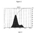
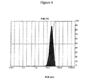
本発明の実施で利用される微粒子材料は不均一形状であり得ることが認識されるべきである。ある材料は球形であり得る。ある材料は円筒状であり得る。ある材料は不規則であり得る。従って、いずれか1つの微粒子材料の「平均粒径」の決定は、測定される寸法および/または粒径分布曲線を決定する正確なプロトコルに依存する。粒径分布曲線を得るプロトコルは、粒径を測定する装置に応じて変わることがある。この詳細な説明を目的として、粒径測定値および分布は、マスタサイザーレーザ散乱分析装置(モードMAM 5005、マルバーンインスツルメント社、ウスターシャー(Worchestershire)、英国)を使用して決定した。 It should be appreciated that the particulate material utilized in the practice of the present invention can be non-uniformly shaped. Some materials can be spherical. Some materials can be cylindrical. Some materials can be irregular. Thus, the determination of the “average particle size” of any one particulate material depends on the exact protocol that determines the measured dimensions and / or particle size distribution curve. The protocol for obtaining the particle size distribution curve may vary depending on the device for measuring the particle size. For purposes of this detailed description, particle size measurements and distributions were determined using a Mastersizer laser scattering analyzer (Mode MAM 5005, Malvern Instruments, Worcestershire, UK).
粒径を決定するために、少量の微粒子材料を水に分散させて、マスターサイザ−装置で分析した。粒径分布を監視して、5回連続で読取値を得た。微粒子材料の平均粒径は次に、同じ体積を有する球の平均直径である、平均体積径D4,3(De Brouckere平均直径)として表される。これは粒径をキャラクタリゼーションするための公知の技法である。従って、本明細書で使用する場合、「平均粒径」という用語は、粒子の実際の形状が多少不規則でありがちであることに留意して、問題の微粒子材料の平均直径であると見なすことができる。 To determine the particle size, a small amount of particulate material was dispersed in water and analyzed with a master sizer device. The particle size distribution was monitored and readings were taken five consecutive times. The average particle size of the particulate material is then expressed as an average volume diameter D4,3 (De Brooker average diameter), which is the average diameter of spheres having the same volume. This is a known technique for characterizing particle size. Thus, as used herein, the term “average particle size” is considered to be the average diameter of the particulate material in question, keeping in mind that the actual shape of the particles tends to be somewhat irregular. Can do.
金属間拡散バリア粒子の層を形成するのに使用され得る無機酸化物の例としては、特にアルミナ、シリカ、ジルコニア、チタニア、セリア、ケイ素、カーバイド、酸化クロム、セラミック材料およびゼオライトが挙げられる。耐火金属としては、特にタングステン、タンタル、レニウム、オスミウム、インジウム、ニオブ、ルテニウム、ハフニウム、ジルコニウム、バナジウムおよびモリブデンが挙げられる。金属間拡散バリア粒子の層を形成するのに使用され得る貴金属エッグシェル触媒に関して、このような貴金属エッグシェル触媒は、同一出願人によるU.S.Patents 7,744,675および7,998,247できわめて詳細に定義および記載され、この全体のテキストは参照により本明細書に組み入れられている。 Examples of inorganic oxides that can be used to form a layer of intermetallic diffusion barrier particles include alumina, silica, zirconia, titania, ceria, silicon, carbide, chromium oxide, ceramic materials, and zeolites, among others. Refractory metals include in particular tungsten, tantalum, rhenium, osmium, indium, niobium, ruthenium, hafnium, zirconium, vanadium and molybdenum. With respect to noble metal egg shell catalysts that can be used to form layers of intermetallic diffusion barrier particles, such noble metal egg shell catalysts are described in US Pat. S. Patents 7,744,675 and 7,998,247 are defined and described in great detail, the entire text of which is incorporated herein by reference.
上記のように、金属間拡散バリアは、多孔性担体の第1の表面への粒子の連続適用として形成される。大まかに言えば、担体を第1の微粒子材料と、次に第2の微粒子材料と、次に第3の微粒子材料というように接触させる。第1の微粒子材料は、多孔性担体の平均孔径より小さい平均粒径(第1の平均粒径)を有する。同様に、第2の微粒子材料の平均粒径(第2の平均粒径)は第1の平均粒径より小さく、第3の微粒子材料の平均粒径(第3の平均粒径)は第2の平均粒径より小さい、などである。 As described above, the intermetallic diffusion barrier is formed as a continuous application of particles to the first surface of the porous support. In general terms, the carrier is brought into contact with the first particulate material, then the second particulate material, and then the third particulate material. The first particulate material has an average particle size (first average particle size) smaller than the average pore size of the porous carrier. Similarly, the average particle size (second average particle size) of the second fine particle material is smaller than the first average particle size, and the average particle size (third average particle size) of the third fine particle material is second. Smaller than the average particle size.
多孔性担体の表面をより小さい粒子でコーティングすると、担体の孔は完全に閉塞されることなく徐々に充填されて、より平滑な担体表面が生成される。この様式で、中間拡散バリアが生成される。 When the surface of the porous carrier is coated with smaller particles, the pores of the carrier are gradually filled without being completely occluded, producing a smoother carrier surface. In this manner, an intermediate diffusion barrier is created.
ここで本発明による詳細な方法に転じると、該方法は、多孔性担体の第1の表面を多孔性担体の第1の平均孔径より小さい第1の平均粒径を有する第1の微粒子材料と接触させて、コート担体上に第1のコート表面を形成するステップを含む。 Turning now to the detailed method according to the invention, the method comprises a first particulate material having a first average particle size smaller than the first average pore size of the porous carrier on the first surface of the porous carrier. Contacting to form a first coated surface on the coated carrier.
本発明のガス分離装置の製造において、微粒子材料(例えば粉末)を多孔性表面に適用する分野の当業者に公知のいずれかの好適な方法によって、微粒子材料層を多孔性基材の第1の表面と接触させる。例えば微粒子材料は、ガスを用いた輸送により、または微粒子材料のペースト、スラリもしくは懸濁物の適用により、または多孔性基材表面への微粒子材料の押し付けもしくは擦り込みによって、多孔性基材の表面に適用され得る。 In the manufacture of the gas separation device of the present invention, the particulate material layer is formed into the first of the porous substrate by any suitable method known to those skilled in the art of applying particulate material (eg, powder) to the porous surface. Contact with the surface. For example, the particulate material may be applied to the surface of the porous substrate by transport with a gas, or by applying a paste, slurry or suspension of the particulate material, or by pressing or rubbing the particulate material onto the surface of the porous substrate. Can be applied.
好ましい実施形態において、接触ステップの少なくとも1つは、担体の厚さにわたってより高い圧力とより低い圧力との圧力差が印加され、より高い圧力が担体の第1の表面側に印加されて行われる。圧力差の印加は、陰圧(即ち担体の第2の表面に印加される真空)または陽圧(即ち担体の第1の表面に印加される圧力)または2つの組合せの使用によって行うことができる。好ましい実施形態において、微粒子材料は、多孔性担体の第2の表面への真空の印加中にスラリとして付着される。 In a preferred embodiment, at least one of the contacting steps is performed with a pressure difference between a higher pressure and a lower pressure applied across the thickness of the carrier and a higher pressure applied to the first surface side of the carrier. . The application of the pressure difference can be done by using negative pressure (ie a vacuum applied to the second surface of the carrier) or positive pressure (ie a pressure applied to the first surface of the carrier) or using a combination of the two. . In a preferred embodiment, the particulate material is deposited as a slurry during application of a vacuum to the second surface of the porous support.
多孔性担体の第1の表面に印加される微粒子材料の品質およびサイズは、微粒子材料を付着させるために利用される方法に応じて多少変わることがある。微粒子材料の適用の主たる目的は、付着されたガス分離膜を最終に担持する、多孔性担体の表面を完全に被覆することである。 The quality and size of the particulate material applied to the first surface of the porous carrier may vary somewhat depending on the method utilized to deposit the particulate material. The main purpose of the application of the particulate material is to completely cover the surface of the porous carrier, which ultimately carries the deposited gas separation membrane.
微粒子材料を多孔性担体の第1の表面と接触した状態で配置して第1のコート表面が形成された後に、担体上に存在するいずれの過剰な第1の微粒子材料も除去される。除去方法は適用方法に応じて変化し得るが、大半の例では、過剰分は摩擦(例えば機械または手動で擦ること)によって除去されると想定される。好ましくは、過剰な微粒子材料を除去するステップは、担体の第2の表面(適用された微粒子材料とは反対の表面)に真空を印加する間に行われる。微粒子材料が湿式工程(例えばスラリまたは懸濁物)を使用して付着された場合、微粒子材料を多孔性担体の孔から引き出すおそれがある、湿潤粒子ケーキのスラブの除去を避けるために、過剰な微粒子材料を除去する前に、コート担体を乾燥させるべきである。 After the particulate material is placed in contact with the first surface of the porous carrier to form the first coated surface, any excess first particulate material present on the carrier is removed. Although the removal method may vary depending on the application method, in most instances it is assumed that the excess is removed by friction (eg, mechanical or manual rubbing). Preferably, the step of removing excess particulate material is performed while applying a vacuum to the second surface of the carrier (the surface opposite the applied particulate material). If the particulate material is deposited using a wet process (eg, slurry or suspension), excess particulate to avoid removal of the wet particle cake slab, which may draw the particulate material out of the pores of the porous carrier. Prior to removal of the particulate material, the coated carrier should be dried.
微粒子材料の適用は、生じるコート多孔性担体の平均孔径を縮小し、多孔性担体の表面粗さを低減するために行うべきである。これらの目標の達成には、微粒子材料の選択における幾つかの変動要因(例えば微粒子材料の選定、適用方法、粒径など)に対処することが含まれる。 Application of the particulate material should be done to reduce the average pore size of the resulting coated porous support and to reduce the surface roughness of the porous support. Achieving these goals includes addressing several variables in the choice of particulate material (eg, particulate material selection, application method, particle size, etc.).
上記に照らして、第1の微粒子材料の第1の平均粒径の選定は、対処すべき重要な変動要因である。平均粒径が過度に小さい第1の微粒子材料を使用すると、多孔性基材の孔の閉塞が生じることがあり、この閉塞は担体の初期平均孔径を縮小するが、多孔性基材のガス流量も商業的に適さないレベルまで低下させることがある。このため、多孔性担体の第1の表面に適用される第1の微粒子材料の第1の平均粒径は、概して担体の初期平均孔径以下であるべきであるが、担体を介したガス流量を許容できないレベルにまで低下させるほど小さい大きさであるべきではない。 In view of the above, the selection of the first average particle size of the first particulate material is an important variable to deal with. When the first particulate material having an excessively small average particle size is used, the pores of the porous substrate may be clogged. This clogging reduces the initial average pore size of the carrier, but the gas flow rate of the porous substrate. May be reduced to a commercially unsuitable level. For this reason, the first average particle size of the first particulate material applied to the first surface of the porous carrier should generally be less than or equal to the initial average pore size of the carrier, but the gas flow rate through the carrier It should not be so small that it drops to an unacceptable level.
同様に、第1の微粒子材料の平均粒径は、これの適用(および過剰分の除去)後に、多孔性担体の第1のコート表面の測定可能な表面粗さが多孔性担体の第1の表面の初期表面粗さよりも小さくなるように選定すべきである。 Similarly, the average particle size of the first particulate material is such that after application (and removal of excess), the measurable surface roughness of the first coated surface of the porous carrier is the first of the porous carrier. It should be chosen to be less than the initial surface roughness of the surface.
要するに、本発明による方法の初期ステップは、(1)初期平均孔径および初期表面粗さを有する多孔性担体を提供すること、ならびに(2)(a)担体の平均孔径を機能的に縮小するためにおよび(b)担体の測定可能な表面粗さを機能的に低減するために、第1の微粒子材料を多孔性担体の第1の表面に適用することを含む。 In summary, the initial steps of the method according to the invention are (1) to provide a porous support having an initial average pore size and initial surface roughness, and (2) (a) to functionally reduce the average pore size of the support. And (b) applying a first particulate material to the first surface of the porous support to functionally reduce the measurable surface roughness of the support.
本発明による方法は、少なくとも1回の追加の繰返しのために、上で論じたステップを連続的に反復することを含む。従って、本発明の好ましい実施形態は、第1のコート担体の第1のコート表面を第1の微粒子材料の第1の平均粒径より小さい第2の平均粒径を有する第2の微粒子材料と接触させて、コート担体上に第2のコート表面を形成するステップを含む。過剰な第2の微粒子材料は次に、以前と同じまたは同様の方法で除去される。 The method according to the invention comprises continuously repeating the steps discussed above for at least one additional iteration. Accordingly, a preferred embodiment of the present invention comprises a second particulate material having a second average particle size smaller than the first average particle size of the first particulate material on the first coated surface of the first coated carrier. Contacting to form a second coated surface on the coated carrier. Excess second particulate material is then removed in the same or similar manner as before.
この第2の接触ステップによって、第1の接触ステップ後に残った小さな間隙および孔に第2の微粒子材料が配置され、第1の微粒子材料の粒径の選定を決定するのと同じ考慮事項が第2の微粒子物質にも等しく適用できる。第2の微粒子材料の平均粒径は、残存する小さい孔に適合するが、これらを完全には閉塞しないように選定されるべきである。これにより、第1のコート表面の平均孔径より小さい平均孔径、前に測定された第1の表面粗さより小さい測定可能な第2の表面粗さおよび許容されるガス流量を有する、第2のコート表面が生じる。 This second contacting step places the second particulate material in the small gaps and holes remaining after the first contacting step, and the same considerations determine the selection of the particle size of the first particulate material. It is equally applicable to the two particulate materials. The average particle size of the second particulate material should be chosen so as to fit the remaining small pores but not completely block them. Thereby, the second coat having an average pore diameter smaller than the average pore diameter of the first coat surface, a measurable second surface roughness smaller than the previously measured first surface roughness and an acceptable gas flow rate A surface is created.
特に好ましい実施形態において、本発明による方法はさらに、第3の接触ステップを行うことを含む。第3の接触ステップは、第2のコート担体を第3の微粒子材料と接触させることを含む。第3の微粒子材料は、第2の平均粒径より小さいが、ガス流量を許容されないレベルまで低下させるほど小さくない、第3の平均粒径を有する。第3の接触ステップは、好ましくは第2の表面粗さより小さい測定可能な第3の表面粗さを有するコート担体上に、第3のコート表面を形成する。 In a particularly preferred embodiment, the method according to the invention further comprises performing a third contact step. The third contacting step includes contacting the second coat carrier with the third particulate material. The third particulate material has a third average particle size that is smaller than the second average particle size but not so small as to reduce the gas flow rate to an unacceptable level. The third contacting step forms a third coated surface on the coated carrier, preferably having a measurable third surface roughness that is less than the second surface roughness.
上の接触ステップは、連続的に小さくなる微粒子サイズを使用して最終接触ステップが行われるまで反復することができ、この時点でマルチコート多孔性担体によって、所望の測定された表面粗さおよび/または所望のガス流量が達成される。 The above contacting step can be repeated using a continuously decreasing particle size until the final contacting step is performed, at which point the multi-coated porous support will provide the desired measured surface roughness and / or Or the desired gas flow rate is achieved.
最終接触ステップにより、最終コート表面が形成される。本発明による方法の好ましい実施形態において、過剰分の拭き取りは微粒子物質の最後の適用後には行われない。最終接触ステップ後に過剰分を残しておくことによって、続いて付着されるいずれの薄膜中にも拡散し得る、いずれの下位金属の露出を防止するのに役立つ。次にコート担体には、微粒子固定ステップおよび付着ステップを含むことが可能である、残りの工程が行われる。 The final contact step forms the final coated surface. In a preferred embodiment of the method according to the invention, excess wiping is not performed after the last application of particulate material. Leaving excess after the final contact step helps to prevent exposure of any underlying metal that can diffuse into any subsequently deposited thin film. The coated carrier is then subjected to the remaining steps, which can include a particulate fixing step and an attachment step.
微粒子物質の種類およびサイズならびに微粒子物質を接触させる方法は、いずれの所与の接触ステップと同じでも異なっていてもよい。 The type and size of the particulate material and the method of contacting the particulate material may be the same or different for any given contact step.
当業者は、上述のステップにおける、特にいずれの所与のステップの微粒子材料の種類およびサイズの選定における、変動に著しい余地があることを認識している。 Those skilled in the art recognize that there is significant room for variation in the above steps, particularly in the choice of particulate material type and size for any given step.
概して、拡散バリア粒子のサイズ(即ち粒子の最大寸法)は、ガス分離システムの作製に使用する多孔性担体の孔の孔径分布に照らして選定される。このため、適切な粒径は変動することがあり、必要または所望ならば50μmを超えることができる。通例、無機酸化物、耐火金属または貴金属エッグシェル触媒の平均粒径は、0.05μmから60μmの範囲または必要ならばこれ以上となる。この範囲は、担体に適用され得る粒子すべてを含む。 In general, the size of the diffusion barrier particles (ie, the largest dimension of the particles) is selected in light of the pore size distribution of the porous support used to make the gas separation system. Thus, the appropriate particle size can vary and can exceed 50 μm if necessary or desired. Typically, the average particle size of the inorganic oxide, refractory metal or noble metal egg shell catalyst will be in the range of 0.05 μm to 60 μm or higher if necessary. This range includes all particles that can be applied to the carrier.
該方法は、次第にサイズが小さくなる粒子の連続塗布を包含するため、適用される微粒子材料の次の各層に使用される粒径は、先に適用された粒子よりも小さい大きさであるべきである。望ましくは、第1の微粒子材料の平均サイズは、8μmから60μmの範囲に、好ましくは10μmから50μmの、より好ましくは12μmから40μmの範囲にあるべきである。 Since the method involves continuous application of particles that are progressively smaller in size, the particle size used for each subsequent layer of applied particulate material should be smaller than the previously applied particles. is there. Desirably, the average size of the first particulate material should be in the range of 8 μm to 60 μm, preferably in the range of 10 μm to 50 μm, more preferably in the range of 12 μm to 40 μm.
微粒子材料の第2の適用に望ましい平均粒径は、1μmから12μmの範囲に、好ましくは2μmから10μmの、より好ましくは3μmから8μmの範囲にあることができる。 The desired average particle size for the second application of the particulate material can be in the range of 1 μm to 12 μm, preferably in the range of 2 μm to 10 μm, more preferably in the range of 3 μm to 8 μm.
粒子の第3の適用では、平均粒径が0.5μmから30μmの範囲であることが望ましいが、第3の適用の粒子の平均粒径の好ましい範囲は1μmから10μm、より好ましくは2μmから8μmである。 In the third application of the particles, it is desirable that the average particle size is in the range of 0.5 μm to 30 μm, but the preferred range of the average particle size of the particles in the third application is 1 μm to 10 μm, more preferably 2 μm to 8 μm. It is.
粒子の第4の適用では、平均粒径は0.05μmから1μmの、好ましくは0.08μmから0.9μmの、最も好ましくは0.1μmから0.8μmの範囲にあるべきである。平均粒径が1μmより小さい粒子は、主として多孔性担体の表面特徴の微調整のために適用されるが、第4の適用は必ずしも必要なステップでない場合がある。第4の適用の必要性は、先に適用された粒子に続いて生じたコート表面の表面粗さに依存している。 For the fourth application of the particles, the average particle size should be in the range of 0.05 μm to 1 μm, preferably 0.08 μm to 0.9 μm, most preferably 0.1 μm to 0.8 μm. Particles with an average particle size of less than 1 μm are mainly applied for fine tuning the surface characteristics of the porous support, but the fourth application may not necessarily be a necessary step. The need for a fourth application depends on the surface roughness of the coated surface that occurs following the previously applied particles.
本発明による方法のいずれの所与の適用についても、粒径の最適で最も経済効率の良い組合せの決定は、当業者が行うことができる。連続適用のための例示的な粒子の分布を実施例に示す。実施例に示す粒径分布および適用の順序は多くの考えられる組合せのうち3つのみを示していることに留意されたい。 For any given application of the method according to the invention, the determination of the optimal and most economical combination of particle sizes can be made by a person skilled in the art. An exemplary particle distribution for continuous application is shown in the examples. Note that the particle size distributions and the order of application shown in the examples show only three of many possible combinations.
本発明の方法による好ましい実施形態において、固定ステップは、最終微粒子材料接触ステップの後に行われる。この固定ステップは、先に付着した微粒子材料を多孔性担体に固定するように機能するいずれの処理ステップも包含し得る。このステップは、利用する微粒子材料の種類に応じて幾つかの形態を取ることができる。 In a preferred embodiment according to the method of the invention, the fixing step is performed after the final particulate material contacting step. This fixing step can include any processing step that functions to fix the previously deposited particulate material to the porous support. This step can take several forms depending on the type of particulate material utilized.
好ましい実施形態において、固定ステップは短時間の無電解メッキ反応を含む。無電解メッキ反応について以下で多少詳細に論じる。このステップは、コート担体を、ガス選択性金属イオンを含有するメッキ溶液中に配置することと、微粒子材料の多孔性担体への付着を固定するために十分な長さだけ反応を行うことを含む。通例、固定ステップの反応時間は1分未満である。固定ステップは、無電解メッキを扱う項で論じるように、非常に低い真空下で行うことができるが、多孔性担体に引き付けるガス選択性金属材料が多すぎないように注意を払う必要がある。この固定ステップは、コート担体上に連続層ガス選択性材料を生成する必要がないため、より完全な付着またはメッキステップとは区別される。 In a preferred embodiment, the fixing step includes a short time electroless plating reaction. The electroless plating reaction is discussed in some detail below. This step involves placing the coat carrier in a plating solution containing gas-selective metal ions and reacting for a length sufficient to fix the adhesion of the particulate material to the porous carrier. . Typically, the reaction time of the fixing step is less than 1 minute. The fixing step can be performed under a very low vacuum, as discussed in the section dealing with electroless plating, but care must be taken not to attract too much gas-selective metallic material to the porous support. This fixing step is distinct from a more complete deposition or plating step because it does not require the production of a continuous layer gas selective material on the coat carrier.
接触ステップおよび固定ステップの最終結果は、一連の粒径を有する勾配中間拡散バリアであり、該バリアでは、最大粒子の大部分が多孔性担体の第1の表面に近接しておよび/または嵌め込まれていて、最小粒子の大部分が概して最大粒子と比べて、第1の表面からさらに離れている。好ましい実施形態において、 微粒子材料のサイズおよび量により、約0.01μmを超える、概して0.01μmから25μmの範囲の厚さを有する中間拡散バリアが生じるが、層厚は0.1μmから20μmの、最も好ましくは1から5μmの範囲にあることが好ましい。 The end result of the contacting and fixing steps is a gradient intermediate diffusion barrier having a series of particle sizes, in which most of the largest particles are in close proximity and / or fitted to the first surface of the porous support. And most of the smallest particles are generally further away from the first surface than the largest particles. In a preferred embodiment, the size and amount of particulate material results in an intermediate diffusion barrier having a thickness greater than about 0.01 μm, generally in the range of 0.01 μm to 25 μm, but the layer thickness is from 0.1 μm to 20 μm, Most preferably, it is in the range of 1 to 5 μm.
先に記載したように、本発明による方法の別の利点は、初期表面粗さより小さい、測定可能な最終表面粗さを有する多孔性担体が生じるということである。表面粗さが判明することは、ガス分離システムの生産にとって重要なデータ点である。下位担体の表面が粗すぎる場合、「谷」を埋めるためにより高価なガス選択性材料が必要であるため、コストが上昇する。下位担体があまりに平滑である場合は、付着したガス選択性材料が担体によく粘着しないことがあり、膜の亀裂発生および剥離を生じる可能性がある。多少大まかな例え話をすれば、ある量の担体表面粗さが付着ガス分離材料の「ベルクロ(マジックテープ)」(登録商標)として作用する必要があるということである。 As described above, another advantage of the method according to the invention is that a porous support is produced having a measurable final surface roughness that is smaller than the initial surface roughness. Knowing the surface roughness is an important data point for the production of gas separation systems. If the surface of the lower carrier is too rough, the cost increases because more expensive gas-selective material is needed to fill the “valley”. If the lower carrier is too smooth, the deposited gas selective material may not adhere well to the carrier, which can result in membrane cracking and delamination. A somewhat rough analogy is that a certain amount of carrier surface roughness needs to act as the “velcro” (registered trademark) of deposited gas separation material.
加えて、約0.7μmを下回る表面粗さは、コート担体の浸透性が低すぎる(即ち生じるガス流量が低すぎる、通例25m3/(m2時バールより低い。)という指標である。好ましい実施形態において、ガス選択性材料を1層以上付着させる前に測定した担体の表面粗さは、0.1μmから3.5μmの、好ましくは1μmから2.5μm、最も好ましくは1.8μmから2μmの間である。 In addition, a surface roughness below about 0.7 μm is an indication that the permeability of the coated carrier is too low (ie the resulting gas flow rate is too low, typically below 25 m 3 / (m 2 bar). In an embodiment, the surface roughness of the carrier measured before depositing one or more layers of gas selective material is from 0.1 μm to 3.5 μm, preferably from 1 μm to 2.5 μm, most preferably from 1.8 μm to 2 μm. Between.
ここでガス分離膜の形成に転じると、1層以上のガス選択性材料が適用されて、多孔性基材の第1の表面を覆う。 Turning now to the formation of a gas separation membrane, one or more layers of gas selective material are applied to cover the first surface of the porous substrate.
ガス選択性材料は、該用語を本明細書で使用する場合、ガスに対して選択透過性であり、このためこのような材料の上層は、選択したガスをこの材料に選択的に通過させながら他のガスの通過を防止するように機能する。考えられるガス選択性金属としては、貴金属、好ましくはパラジウム、白金、金、銀、ロジウム、レニウム、ルテニウム、イリジウム、ニオブおよびこれの2つ以上の合金である。本発明の好ましい実施形態において、ガス選択性材料は、水素選択性金属、例えば白金、パラジウム、金、銀および合金を含むこれの組合せである。水素利用のための最も好ましいガス選択性材料は、パラジウム、銀ならびにパラジウムおよび銀の合金である。 A gas-selective material is selectively permeable to a gas as the term is used herein so that an upper layer of such a material allows a selected gas to pass selectively through the material. It functions to prevent the passage of other gases. Possible gas-selective metals are noble metals, preferably palladium, platinum, gold, silver, rhodium, rhenium, ruthenium, iridium, niobium and alloys of two or more thereof. In a preferred embodiment of the invention, the gas selective material is a hydrogen selective metal such as platinum, palladium, gold, silver and combinations thereof including alloys. The most preferred gas selective materials for hydrogen utilization are palladium, silver, and alloys of palladium and silver.
ガス選択性材料は、表面処理多孔性基材上に当業者に公知のいずれの好適な手段または方法によっても付着される。考えられる付着方法としては、無電解メッキ、熱付着、化学気相蒸着、電気メッキ、スプレー付着、スパッタコーティング、電子ビーム蒸着、イオンビーム蒸着およびスプレー熱分解が挙げられる。本明細書で使用する場合、「無電解メッキ」または「メッキ」という用語は、ガス選択性材料を付着するために使用される多様な技術の特定の部分集合と見なすことができる。 The gas selective material is deposited on the surface treated porous substrate by any suitable means or method known to those skilled in the art. Possible deposition methods include electroless plating, thermal deposition, chemical vapor deposition, electroplating, spray deposition, sputter coating, electron beam deposition, ion beam deposition and spray pyrolysis. As used herein, the term “electroless plating” or “plating” can be considered a specific subset of the various techniques used to deposit gas selective materials.
好ましい付着方法は無電解メッキである。ガス選択性材料をコート多孔性基材上に付着させるための好適な無電解メッキ法の一例は、Pub.No.US 2006/0016332に開示されている方法であり、これの開示は参照により本明細書に組み入れられている。ガス選択性材料をコート多孔性基材上に付着させるための好適な無電解メッキ法の別の例は、同時係属で同一出願人によるUS Patent Application Serial No.61/560,522に開示されている方法であり、これの開示は参照により本明細書に組み入れられている。 A preferred deposition method is electroless plating. An example of a suitable electroless plating method for depositing a gas selective material on a coated porous substrate is described in Pub. No. US 2006/0016332, the disclosure of which is incorporated herein by reference. Another example of a suitable electroless plating method for depositing a gas-selective material on a coated porous substrate is described in co-pending and commonly assigned US Patent Application Serial No. 61 / 560,522, the disclosure of which is incorporated herein by reference.
ガス選択性材料を付着させるための好適な無電解メッキ法のさらなる例は、US 7,390,536および7,727,596に開示され、これのどちらもこれの全体が参照により組み入れられている。PdおよびAg付着の反応速度に対する温度、メッキ溶液成分の濃度および多孔性担体の回転の効果を示す無電解メッキのさらなる例は、Ayturk,et.al.,Electroless Pd and Ag deposition kinetics of the composite Pd and Pd/Ag membranes synthesized from agitated plating baths,Journal of Membrane Science,330(2009)233−245(「Ayturk論文」)にて論じられ、これの全体は参照により組み入れられている。 Further examples of suitable electroless plating methods for depositing gas selective materials are disclosed in US 7,390,536 and 7,727,596, both of which are incorporated by reference in their entirety. . Additional examples of electroless plating showing the effects of temperature, plating solution component concentration and porous support rotation on the kinetics of Pd and Ag deposition are described in Ayturk, et. al. , Electroless Pd and Ag deposition kinetics of the composition Pd and Pd / Ag membranes synthesized from aggregated plating baths, Journal of Mem. It is incorporated by.
大まかには、無電解メッキ工程は、酸化還元反応を使用して、電流を通すことなく金属を物体に付着させる。無電解技術は、温和な還元剤を使用する錯化金属の還元を包含する。例えばパラジウムの付着は以下の式によって行うことができる:
2Pd(NH3)42Cl+H2NNH2+4NH4OH→2Pd+N2+8NH3+4NH4Cl+4H2O。
In general, the electroless plating process uses a redox reaction to deposit metal onto an object without passing an electric current. Electroless techniques include the reduction of complexed metals using mild reducing agents. For example, palladium deposition can be performed by the following formula:
2Pd (NH 3 ) 4 2Cl + H 2 NNH 2 + 4NH 4 OH → 2Pd + N 2 + 8NH 3 + 4NH 4 Cl + 4H 2 O.
概して、公知の無電解メッキ工程において、メッキ槽には公知の量のメッキ溶液が投入される。メッキ溶液は、公知の濃度のガス選択性金属イオン(例えばパラジウムまたは金)および他の成分を含有する。次にメッキされる物品(例えば多孔性担体)を、メッキ槽にメッキ溶液と接触させて一定期間にわたって配置する。この期間に酸化還元反応が起こり、ガス選択性金属の薄層が物品に付着する。無電解メッキがガス分離膜の好ましい作製方法であるのは、メッキ溶液がメッキする物体のすべての部分に浸漬して、端部に沿って穴の内側に、および電気メッキによって均一なメッキが困難である不規則形状の物体を覆って金属を付着させる傾向があるためである。 Generally, in a known electroless plating process, a known amount of plating solution is charged into the plating tank. The plating solution contains known concentrations of gas-selective metal ions (eg, palladium or gold) and other components. The article to be plated (eg, porous carrier) is then placed in a plating bath over a period of time in contact with the plating solution. During this period, a redox reaction occurs and a thin layer of gas-selective metal adheres to the article. Electroless plating is the preferred method for producing gas separation membranes because the plating solution is immersed in every part of the object to be plated, inside the hole along the edges and by electroplating is difficult This is because the metal tends to adhere over the irregularly shaped object.
読者への助けとなるように、無電解メッキは、混合ガス流から水素ガスを分離するためのパラジウム膜を形成する状況にて論じられる。この状況で助けとなるものは、特許請求の範囲を制限するものとして解釈されない。 As an aid to the reader, electroless plating is discussed in the context of forming a palladium film for separating hydrogen gas from a mixed gas stream. What is helpful in this situation is not to be construed as limiting the scope of the claims.
ひとたび所望の多孔性担体が選ばれ、金属間拡散層を用いて上で論じた様式で作製されると、多孔性担体は一定量のメッキ溶液を含有するメッキ槽内に配置されて、無電解メッキの工程が開始される。しかし、本発明による無電解メッキの機構を論じる前に、当分野における標準慣行となった多孔性担体を作製するための必須ではないステップ、即ち多孔性担体の前処理または「シーディング」(担体を「活性化すること」としても公知である。)について論じることが必要である。 Once the desired porous support is selected and made in the manner discussed above using an intermetallic diffusion layer, the porous support is placed in a plating bath containing a certain amount of plating solution and electroless. The plating process is started. However, before discussing the mechanism of electroless plating according to the present invention, a non-essential step to make a porous support that has become standard practice in the art, namely pre-treatment or “seeding” of the porous support (support Is also known as “activating”).
多孔性担体の「シーディング」は、選ばれたガス選択性材料の粒子によって多孔性担体を前処理して、ガス選択性材料の次の層の付着を補助する核形成部位を提供することを含む。この前処理は複数の形を取ることが可能であり、この形の幾つかは、金属間拡散バリアを形成する工程と重複することがある。例えば、本発明の一実施形態において、多孔性担体は、これをアルミナの層、またはジルコニアの安定化形、例えばパラジウムもしくは金を含有するイットリア安定化ジルコニアによってコーティングすることによって前処理される。 “Seeding” of the porous carrier means that the porous carrier is pretreated with particles of the selected gas-selective material to provide a nucleation site that assists in the deposition of the next layer of gas-selective material. Including. This pretreatment can take several forms, some of which may overlap with the process of forming the intermetallic diffusion barrier. For example, in one embodiment of the present invention, the porous support is pretreated by coating it with a layer of alumina or a stabilized form of zirconia, such as yttria stabilized zirconia containing palladium or gold.
または多孔性担体は、貴金属エッグシェル触媒の層を多孔性担体の表面に配置することによって前処理できる。このようなエッグシェル触媒の層を多孔性担体に施すための方法は、参照により本明細書に組み入れられている、US Patent 7,744,675に教示されている。 Alternatively, the porous support can be pretreated by placing a layer of noble metal egg shell catalyst on the surface of the porous support. A method for applying such a layer of egg shell catalyst to a porous support is taught in US Pat. No. 7,744,675, incorporated herein by reference.
同様に、前処理は、参照により本明細書に組み入れられているUS Patent 7,959,711に記載されているように、ガス選択性金属または金属合金のナノ粉末またはナノ粒子を多孔性担体の表面に施す形をとることができる。 Similarly, the pre-treatment may be performed on a porous carrier nanoparticle or nanoparticle of a gas-selective metal or metal alloy as described in US Patent 7,959,711, which is incorporated herein by reference. It can take the form applied to the surface.
前処理のさらなる方法は、多孔性担体を液状活性化組成物によって処理することである。例えば、多孔性担体は、すず(II)ジクロリドの酸性水溶液に浸漬して、次に酸性パラジウム(II)ジクロリド水溶液浴に浸漬して、表面にパラジウムをシーディングすることができる。多孔性担体をパラジウム塩で処理して、続いてヒドラジンで処理することは、パラジウム核を多孔性担体に付着させる別の方法である。 A further method of pretreatment is to treat the porous carrier with a liquid activation composition. For example, the porous carrier can be immersed in an acidic aqueous solution of tin (II) dichloride and then in an aqueous bath of acidic palladium (II) dichloride to seed palladium on the surface. Treating the porous support with a palladium salt followed by hydrazine is another way of attaching the palladium nuclei to the porous support.
前処理のまたさらなる方法は、多孔性担体の表面に少量のガス選択性材料によって「シーディング」するための、短時間のメッキ反応(以下で論じる。)を行うことである。本発明による方法において、この前処理方法は、上で論じた固定ステップに相当する。 A still further method of pretreatment is to perform a short plating reaction (discussed below) to “seeding” the surface of the porous support with a small amount of gas selective material. In the method according to the invention, this pretreatment method corresponds to the fixed step discussed above.
ここで無電解メッキ工程に転じると、一定濃度のガス選択性金属イオンを有するメッキ溶液が提供される。本発明の実施で用いるメッキ溶液に含有されるガス選択性金属イオンとしては、多孔性担体の表面上に層として配置される場合に、ガスに対して選択的に透過性である特性を有するいずれの金属または金属合金または合金可能な金属の混合物が挙げられる。ガス選択性金属は水素選択性であることが好ましい。 Turning now to the electroless plating process, a plating solution having a constant concentration of gas-selective metal ions is provided. As the gas-selective metal ions contained in the plating solution used in the practice of the present invention, any gas having a property of being selectively permeable to gas when arranged as a layer on the surface of the porous carrier. Or a mixture of metals or metal alloys or alloyable metals. The gas selective metal is preferably hydrogen selective.
このような溶液を形成する方法は、当業者に周知であり、本明細書で詳細に論じる必要はない。サンプルメッキ溶液としては、Ayturk文献;US Patent 7,727,596;US Patent 7,390,536;US Patent 7,744,675;US Published Application 2009/0120293およびUS Patent Application Serial No.61/560,522に記載されている組成物を用いたメッキ溶液が挙げられる。代表的なメッキ溶液は、金属イオン源(例えばPdCl2、Pd(NH3)4Cl2、Pd(NH3)4Br2、Pd(NH3)(NO3)2)、錯化剤(例えばエチレンジアミンテトラ酢酸(EDTA)、NH4OHまたはエチレンジアミン(EDA))、還元剤(NH2NH2、NaH2PO2、H2O、トリメチルアミンボラン)、安定剤および加速剤を含む。 Methods for forming such solutions are well known to those skilled in the art and need not be discussed in detail herein. Sample plating solutions include Ayturk literature; US Patent 7,727,596; US Patent 7,390,536; US Patent 7,744,675; US Published Application 2009/0120293 and US Patent Application Serial No. A plating solution using the composition described in 61 / 560,522 is mentioned. Typical plating solutions include metal ion sources (eg, PdCl 2 , Pd (NH 3 ) 4 Cl 2 , Pd (NH 3 ) 4 Br 2 , Pd (NH 3 ) (NO 3 ) 2 ), complexing agents (eg, Ethylenediaminetetraacetic acid (EDTA), NH 4 OH or ethylenediamine (EDA)), reducing agents (NH 2 NH 2 , NaH 2 PO 2 , H 2 O, trimethylamine borane), stabilizers and accelerators.
多孔性担体はメッキ槽内に配置され、メッキ溶液と接触させられる。多孔性担体は、メッキ溶液から多孔性担体のコート表面(例えば外表面)上へのガス選択性金属イオンの無電解付着を促進するのに十分な条件下で、一定期間にわたるメッキ溶液との接触が維持される。 The porous carrier is placed in a plating bath and brought into contact with the plating solution. The porous carrier is contacted with the plating solution for a period of time under conditions sufficient to promote electroless deposition of gas-selective metal ions from the plating solution onto the coated surface (eg, outer surface) of the porous carrier. Is maintained.
温度範囲、時間、メッキ溶液成分などを含む無電解付着を促進するのに十分な条件は、当業者に公知であり、上記の特許、特許出願およびAyturk論文で論じられている。これらの条件は工程の装置および製造者の特定の目標に応じて変化し得るが、多くの例において、無電解メッキステップは、20℃から80℃の範囲の、より好ましくは30℃から70℃の範囲の、最も好ましくは40℃から60℃の範囲の温度にて行われることが想定される。同様に、メッキ反応を行う時間は、他のメッキ条件に応じて広い範囲にわたって変化することがある。好ましい実施形態において、メッキ反応は、10分から3時間以上の間の時間で行う。好ましい実施形態において、反応は30分から120分の間続く。45分から90分の反応時間が特に好ましい。 Conditions sufficient to promote electroless deposition, including temperature range, time, plating solution components, etc. are known to those skilled in the art and discussed in the above-mentioned patents, patent applications and Ayturk papers. While these conditions may vary depending on the process equipment and the manufacturer's specific goals, in many instances the electroless plating step is in the range of 20 ° C to 80 ° C, more preferably 30 ° C to 70 ° C. It is envisaged that it is carried out at a temperature in the range of 40 ° C to 60 ° C, most preferably. Similarly, the time for performing the plating reaction may vary over a wide range depending on other plating conditions. In a preferred embodiment, the plating reaction is performed for a time between 10 minutes and 3 hours or more. In a preferred embodiment, the reaction lasts between 30 minutes and 120 minutes. A reaction time of 45 minutes to 90 minutes is particularly preferred.
1回以上のメッキステップの間に担体の厚さに圧力差を印加することによって、ガスタイト膜を得るために必要なメッキの反復数が減少することが示されている。従って、本発明による方法の好ましい実施形態は、付着/メッキステップの1つ以上の間に担体の厚さへの圧力差の印加を利用する。大まかに言えば、圧力差の印加は、多孔性担体の一方の表面(ガス選択性材料が上に付着されている表面)により高い圧力を、反対の表面により低い圧力を生成することよりなる。 It has been shown that applying a pressure difference to the thickness of the carrier during one or more plating steps reduces the number of plating iterations required to obtain a gastight film. Accordingly, preferred embodiments of the method according to the present invention utilize the application of a pressure differential to the thickness of the carrier during one or more of the deposition / plating steps. Broadly speaking, the application of a pressure differential consists of producing a higher pressure on one surface of the porous support (the surface on which the gas-selective material is deposited) and a lower pressure on the opposite surface.
このような圧力差を生成する1つの方式は、ガス選択性金属が上に付着されている表面と反対の多孔性担体の面(即ち多孔性担体の第2の表面)に真空を印加することによる。真空は、より多くのガス選択性金属を多孔性担体の孔中に吸引し、これによりガスタイト膜をより少ないステップでの生成を補助することができる。しかし、工程の早すぎる時期に印加する真空が過度に高いと、またはより低い真空をあまりに長期にわたって印加すると、過剰なガス選択性金属が孔中に吸引されることがあり、これにより孔の長さにガス選択性材料が充填されて非常に厚い膜が作製され、水素に対する透過性が低くなる。好ましい実施形態において、真空はアニーリング済み膜層が液密となるまで印加されず、このことは多すぎるガス選択性材料が多孔性担体中に吸引されるのを防止する助けとなる。真空印加に対するこのような制限の考えられる1つの例外は、先に論じた固定ステップの間である。この例では、弱い真空を印加して、少量のガス選択性材料を担体中に吸引することができる。 One way to create such a pressure differential is to apply a vacuum to the surface of the porous support opposite to the surface on which the gas-selective metal is deposited (ie, the second surface of the porous support). by. The vacuum can draw more gas-selective metal into the pores of the porous support, thereby helping to produce a gastight membrane in fewer steps. However, if the vacuum applied too early in the process is too high, or if a lower vacuum is applied for too long, excess gas-selective metal may be drawn into the pores, which can Moreover, a very thick membrane is produced by filling the gas selective material, and the permeability to hydrogen is lowered. In a preferred embodiment, a vacuum is not applied until the annealed membrane layer is liquid tight, which helps to prevent too much gas selective material from being drawn into the porous support. One possible exception to such limitations on vacuum application is during the fixed steps discussed above. In this example, a weak vacuum can be applied to draw a small amount of gas selective material into the carrier.
圧力差を生成する他の考えられる方法としては、多孔性担体の第1の表面への陽圧の印加(即ち担体のメッキ溶液側への圧力の印加)または陽圧および真空の組合せが挙げられる。無電解メッキ工程中の圧力差の生成は、参照により本明細書に組み入れられている、同一出願人によるUS Patent Application Serial No.61/560,552にて相当詳しく論じられている。 Other possible ways of generating the pressure differential include the application of positive pressure to the first surface of the porous support (ie, application of pressure to the plating solution side of the support) or a combination of positive pressure and vacuum. . The generation of the pressure differential during the electroless plating process is described in US Pat. Application Serial No. 1 by the same applicant, which is incorporated herein by reference. 61 / 560,552, discussed in considerable detail.
複合ガス選択性膜によって液密、ガスタイトおよびガス選択性状態が達成される時点を決定するために、1つまたは複数のアニーリング済み膜層の試験を定期的に、好ましくは各付着ステップ後に行うが、商業用途ではより長期の間隔が使用されると考えられる。好ましい実施形態において、アニーリング済み膜層は、これの液体に対する密度を判定するために定期的に試験される。 One or more annealed membrane layers are tested periodically, preferably after each deposition step, to determine when the liquid tight, gas tight and gas selective states are achieved by the composite gas selective membrane. Longer intervals would be used in commercial applications. In a preferred embodiment, the annealed membrane layer is periodically tested to determine its density for liquid.
アニーリング済み膜層の密度を試験する代表的な方法は、多孔性担体を液体、通常は水に暴露しながら、定義された真空レベルを多孔性担体の1つの表面、通例、アニーリング済み膜層と反対の表面に印加することによる。水がアニーリング済み膜層を通じて吸引されない場合、システムはこの特定の圧力差では液密であると見なされる。 A typical method for testing the density of an annealed membrane layer is to expose a porous carrier to a liquid, usually water, while applying a defined vacuum level to one surface of the porous carrier, typically an annealed membrane layer. By applying to the opposite surface. If water is not drawn through the annealed membrane layer, the system is considered liquid tight at this particular pressure differential.
メッキ反応を決められた期間にわたって行った後、多孔性担体および付着したガス選択性金属膜をメッキ溶液から取り出す。この後、担体および膜を洗浄、乾燥およびアニーリングすると、アニーリング済みの膜層を有するアニーリング済み担持膜が提供される。 After performing the plating reaction for a predetermined period, the porous carrier and the attached gas-selective metal film are removed from the plating solution. This is followed by washing, drying and annealing of the support and membrane to provide an annealed carrier membrane having an annealed membrane layer.
付着ガス選択性材料、特に貴金属のアニーリングは、当分野で公知である。2つの例示的なアニーリング工程は、US Patent 7,727,596および同一出願人によるUS Published Patent Application 2009/0120293で論じられている。 Deposited gas selective materials, especially the annealing of noble metals, are known in the art. Two exemplary annealing steps are discussed in US Patent 7,727,596 and US Published Patent Application 2009/0120293 by the same applicant.
7,727,596で利用するアニーリング工程は、製造または商業使用のどちらかの間のガス選択性膜の亀裂発生の考えられる原因であると思われる。より詳細には、‘596特許は、新たに付着したガス選択性材料が水素の存在下で250℃以下の温度にてアニーリングされるアニーリングステップを教示している。このような条件下でアニーリングされた膜は、商業使用中にまたは次のアニーリングステップに亀裂発生が頻発し、このため商業使用には不適となることが認められている。このことはおそらく、パラジウムヒドリドのアルファ形およびベータ形が存在するためである。アルファ形およびベータ形は、異なる結晶サイズを有し、パラジウム膜に亀裂を発生させることが公知である。 The annealing process utilized in 7,727,596 appears to be a possible cause of cracking of gas selective membranes during either manufacturing or commercial use. More specifically, the '596 patent teaches an annealing step in which newly deposited gas selective material is annealed at a temperature of 250 ° C. or less in the presence of hydrogen. It has been found that films annealed under such conditions frequently crack during commercial use or in the next annealing step, which makes them unsuitable for commercial use. This is probably due to the presence of alpha and beta forms of palladium hydride. Alpha and beta forms are known to have different crystal sizes and cause cracks in palladium films.
本発明による方法は、各種のアニーリングステップを利用する。本発明による方法において、多孔性基材がガス選択性材料の層によってコーティングまたはメッキされるたびに、コート多孔性基材はこの後、不活性ガス雰囲気の存在下または不活性ガス雰囲気中でより低い温度にて、熱処理またはアニーリングされる。より詳細には、アニーリングは水素の非存在下で、アニーリング温度が少なくとも250℃、好ましくは少なくとも300℃、より好ましくは少なくとも350℃となるまで行われる。アニーリング温度がひとたび250℃、好ましくは300℃、より好ましくは350℃に達すると、水素および酸素がアニーリングステップに存在することがある。別の言い方をすれば、好ましい実施形態において、アニーリングステップが水素含有雰囲気中で行われるが、ただし温度が最低300℃、好ましくは少なくとも350℃、より好ましくは少なくとも400℃に達した後であるアニーリングステップを非常に高温(例えば600℃以上)にすることができるが、多くの例では、アニーリングステップは350℃から550℃の間の、最も好ましくは400℃から500℃の間の温度で行われる。好ましい実施形態において、膜が複数の付着ステップの間に冷却されるときに、水素がシステムから放出される。通例、膜の冷却が開始するときに、システムに不活性ガスを流入させることによって水素が放出されるので、300℃、好ましくは400℃に達するときには、水素は存在しない。 The method according to the invention makes use of various annealing steps. In the process according to the invention, each time the porous substrate is coated or plated with a layer of gas-selective material, the coated porous substrate is then treated in the presence of an inert gas atmosphere or in an inert gas atmosphere. Heat treated or annealed at low temperature. More specifically, annealing is performed in the absence of hydrogen until the annealing temperature is at least 250 ° C, preferably at least 300 ° C, more preferably at least 350 ° C. Once the annealing temperature reaches 250 ° C., preferably 300 ° C., more preferably 350 ° C., hydrogen and oxygen may be present in the annealing step. In other words, in a preferred embodiment, the annealing step is performed in a hydrogen-containing atmosphere, provided that the annealing is at least 300 ° C, preferably at least 350 ° C, more preferably at least 400 ° C. Although the step can be very hot (eg, 600 ° C. or higher), in many instances the annealing step is performed at a temperature between 350 ° C. and 550 ° C., most preferably between 400 ° C. and 500 ° C. . In a preferred embodiment, hydrogen is released from the system when the membrane is cooled during multiple deposition steps. Typically, when the membrane begins to cool, hydrogen is released by flowing an inert gas into the system so that when 300 ° C, preferably 400 ° C is reached, no hydrogen is present.
この熱処理ステップでの使用が考えられる不活性ガスとしては、窒素、ヘリウム、アルゴン、ネオンおよび二酸化炭素が挙げられる。アニーリングステップでの使用に好ましい不活性ガスは、窒素、アルゴン、ネオンおよび二酸化炭素からなる群より選択されるものであり、熱処理での使用に最も好ましい不活性ガスは窒素である。 Inert gases that may be used in this heat treatment step include nitrogen, helium, argon, neon and carbon dioxide. The preferred inert gas for use in the annealing step is selected from the group consisting of nitrogen, argon, neon and carbon dioxide, and the most preferred inert gas for use in the heat treatment is nitrogen.
アニーリングステップが行われるガス状雰囲気は、アニーリング温度がひとたび少なくとも300℃(好ましくはこれ以上)に達したら、多少の水素を有するべきである。メッキ多孔性基材のアニーリングステップ中に使用されるガス状雰囲気は、3から100%の水素および97から0%の不活性ガスの混合物を含むべきである。 The gaseous atmosphere in which the annealing step is performed should have some hydrogen once the annealing temperature has reached at least 300 ° C. (preferably above). The gaseous atmosphere used during the annealing step of the plated porous substrate should include a mixture of 3 to 100% hydrogen and 97 to 0% inert gas.
アニーリングは、多孔性基材の第1の表面を覆うガス選択性材料(金属)の薄層を十分に処理する温度にて行われる。必要とされるアニーリング温度は、多孔性基材にメッキされている特定の金属または金属合金およびこれの層の厚さにいくらか依存するが、熱処理温度は概して、少なくとも300℃から800℃の範囲にあるべきである好ましい熱処理温度は325℃から700℃の範囲にあり、最も好ましくは、熱処理温度は350℃から550℃の範囲にある。 Annealing is performed at a temperature that sufficiently treats a thin layer of gas-selective material (metal) covering the first surface of the porous substrate. The required annealing temperature depends somewhat on the specific metal or metal alloy being plated on the porous substrate and the thickness of the layer, but the heat treatment temperature is generally at least in the range of 300 ° C to 800 ° C. The preferred heat treatment temperature that should be is in the range of 325 ° C. to 700 ° C., most preferably the heat treatment temperature is in the range of 350 ° C. to 550 ° C.
アニーリングステップは、ガス選択性材料層の必要な処理を与え、次の一連のメッキ、研磨およびアニーリングのために該層を準備するために十分な期間にわたって行われる。アニーリング期間はこのため、長くは48時間以上の範囲であり得るが、通例のアニーリング期間は0.1時間から12時間の範囲にある。しかしアニーリング時間は、本発明の利点を達成するのに必要なガス選択性金属の層の処理を提供するのに必要な時間のみに最短縮することが好ましい。このような期間は、0.2から10時間の範囲に、または0.3時間から4時間の範囲にあることさえ期待される。 The annealing step is performed for a period of time sufficient to provide the necessary processing of the gas selective material layer and prepare the layer for the next series of plating, polishing and annealing. The annealing period can thus be in the range of 48 hours or longer, but the typical annealing period is in the range of 0.1 to 12 hours. However, it is preferred that the annealing time be minimized to only the time required to provide the processing of the gas selective metal layer necessary to achieve the advantages of the present invention. Such a period is expected to be in the range of 0.2 to 10 hours, or even in the range of 0.3 hours to 4 hours.
アニーリングが行われる圧力は、0.5気圧(絶対)から20気圧の範囲にあることが可能である。より通例には、熱処理圧力は0.8気圧から10気圧の範囲にある。 The pressure at which annealing is performed can be in the range of 0.5 atmospheres (absolute) to 20 atmospheres. More typically, the heat treatment pressure is in the range of 0.8 to 10 atmospheres.
研究は、‘596特許のアニーリングステップと比較した、本発明によるアニーリングステップで見られる利点をさらに定義するために進行中であるが、現時点で、付着した金属の粒子成長パラメータは、膜安定性を上昇させ、高温での変化に膜安定性が耐えられるように補助すると考えられる。例えば‘596特許は、水素の存在下での低温におけるアニーリングによりパラジウムの粒子成長を遅延または防止され、理論的にこれが基材のより均一な被覆につながると述べている。実際にこれらの条件は、パラジウムヒドリドのアルファ形およびベータ形が共存するために、パラジウム層の亀裂発生を引き起こす傾向がある。 Research is ongoing to further define the benefits seen with the annealing step according to the present invention compared to the annealing step of the '596 patent, but at present, the particle growth parameters of the deposited metal are dependent on film stability. It is thought to help increase the film stability to withstand changes at high temperatures. For example, the '596 patent states that annealing at low temperatures in the presence of hydrogen retards or prevents palladium particle growth, which theoretically leads to a more uniform coating of the substrate. In fact, these conditions tend to cause cracking of the palladium layer due to the coexistence of the alpha and beta forms of palladium hydride.
他方、出願人は、アニーリング温度の上昇による粒子成長の促進が、特にガス選択性材料の層が複数のメッキステップの間に研磨される場合に、有益な効果を有すると思われることを発見した。研磨ステップについて下でより詳細に論じる。粒子を研磨してこれらを効果的に開孔中に塗り込んで、均一な金属層を形成することには、幾つかのプラスの効果があると考えられる。このような様式で形成されたガス分離システムは、‘596特許の方法によって形成されたシステムと比較して、高い操作温度での亀裂発生に耐えることが観察されている。 On the other hand, Applicants have found that the promotion of particle growth by increasing the annealing temperature appears to have a beneficial effect, particularly when the layer of gas selective material is polished during multiple plating steps. . The polishing step is discussed in more detail below. It is believed that there are several positive effects in polishing the particles and effectively coating them into the apertures to form a uniform metal layer. It has been observed that gas separation systems formed in this manner resist cracking at high operating temperatures compared to systems formed by the method of the '596 patent.
アニーリング後、多孔性担体はこれのアニーリング済みの担持膜層と共に研磨/研削される。研磨によって、表面の異常や変形を最小限に抑えることにより、ならびに薄膜層に存在し得る開口部、例えば亀裂、ピンホールおよび他の欠陥を充填することにより、さらにメッキを行うためにメッキ層の表面が改良される。研削および研磨法は、US Published Patent Application 2009/0120287に開示されている。 After annealing, the porous carrier is polished / ground with its annealed carrier film layer. By polishing the surface of the plating layer for further plating by minimizing surface anomalies and deformations and by filling in openings that may be present in the thin film layer, such as cracks, pinholes and other defects. The surface is improved. Grinding and polishing methods are disclosed in US Published Patent Application 2009/0120287.
液密、ガスタイトおよびガス選択性である複合ガス選択性膜が生成されるまで、上のメッキステップ、洗浄ステップ、アニーリングステップおよび研削ステップが反復される。 The above plating, cleaning, annealing and grinding steps are repeated until a composite gas selective membrane that is liquid tight, gas tight and gas selective is produced.
複合ガス選択性膜によって液密、ガスタイトおよびガス選択性状態が達成される時点を決定するために、1つまたは複数のアニーリング済み膜層の試験を定期的に、好ましくは各付着ステップ後に、または商業用途にて好適なスケジュールで行う。適切な試験方法は当業者に公知であり、本明細書で具体的に記載する必要はない。 Test the one or more annealed membrane layers periodically, preferably after each deposition step, to determine when the liquid tight, gas tight and gas selective states are achieved by the composite gas selective membrane, or Perform on a schedule suitable for commercial use. Appropriate testing methods are known to those skilled in the art and need not be specifically described herein.
膜システムが可能な限り高い選択性を有することが最良であるが、通例、膜システムで水素に許容されるまたは所望の選択性は、窒素、二酸化炭素またはメタンに対して、少なくとも約100である。より通例には、膜システムの所望の選択性は少なくとも500であり、最も通例には、膜システムの所望の選択性は1000を超えるべきである。膜システムの選択性は、5,000さえ、または10,000さえ超え、このため膜システムがこのような選択性を有することは望ましい。 It is best that the membrane system has the highest possible selectivity, but typically the acceptable or desired selectivity for hydrogen in the membrane system is at least about 100 over nitrogen, carbon dioxide or methane. . More typically, the desired selectivity of the membrane system should be at least 500, and most typically the desired selectivity of the membrane system should exceed 1000. The selectivity of the membrane system is even greater than 5,000, or even 10,000, so it is desirable for the membrane system to have such selectivity.
基材上に所望の厚さのガス選択性金属層を得るのに必要な回数だけメッキ操作が繰返される。多孔性担体上に担持された膜層の通例の厚さは、0.001μmから30μmの範囲にあり得るが、多くのガス分離用途では、この範囲の上端にある膜厚は厚すぎて、所望のガス分離を可能にする合理的なガス流量を提供できないことがある。概して、膜厚は20μm未満、好ましくは10μm未満であるべきである。上述したように、請求する発明は、商業的に許容される膜を他の公知の工程と比較してより少ないステップで得る能力を示している。 The plating operation is repeated as many times as necessary to obtain the desired thickness of the gas-selective metal layer on the substrate. The typical thickness of the membrane layer supported on the porous support can be in the range of 0.001 μm to 30 μm, but for many gas separation applications, the film thickness at the top of this range is too thick and may be desired. It may not be possible to provide a reasonable gas flow rate that allows for the separation of gases. In general, the film thickness should be less than 20 μm, preferably less than 10 μm. As mentioned above, the claimed invention demonstrates the ability to obtain commercially acceptable membranes in fewer steps compared to other known processes.
最後に、本明細書に記載する本発明の方法によって作製されるガス分離膜システムまたはこれの要素は、ガス混合物から選択されたガスの選択的分離で使用され得る。ガス分離膜は、とりわけ高温用途において、水素含有ガス流から水素を分離するのに特に有用である。 Finally, the gas separation membrane system or element thereof made by the inventive method described herein can be used in the selective separation of a selected gas from a gas mixture. Gas separation membranes are particularly useful for separating hydrogen from hydrogen-containing gas streams, especially in high temperature applications.
ガス分離膜システムが使用され得る高温用途の一例は、一酸化炭素および水素を得るための炭化水素、例えばメタンの水蒸気改質と、続いての、二酸化炭素を得るための水素いわゆる水性ガスシフト反応における、生じた一酸化炭素と水との反応においてである。これらの触媒反応は、平衡型反応であり、本発明のガス分離膜は、水素収率に有利となるように平衡条件を向上させるために、反応を行いながら、生じた水素を同時分離するのに有用である。反応が同時に行われる反応条件は、400℃から600℃の範囲の反応温度および1から60バールの範囲の反応圧力を含むことができる。 An example of a high temperature application in which a gas separation membrane system can be used is in the steam reforming of hydrocarbons to obtain carbon monoxide and hydrogen, such as methane, followed by hydrogen to obtain carbon dioxide, the so-called water gas shift reaction. In the reaction of the resulting carbon monoxide with water. These catalytic reactions are equilibrium reactions, and the gas separation membrane of the present invention simultaneously separates the generated hydrogen while conducting the reaction in order to improve the equilibrium conditions so as to be advantageous for the hydrogen yield. Useful for. The reaction conditions under which the reactions are carried out simultaneously can include a reaction temperature in the range of 400 ° C. to 600 ° C. and a reaction pressure in the range of 1 to 60 bar.
以下の実施例は、本発明をさらに例証するために与えられているが、これらはこれの範囲を制限するものとして解釈されるべきではない。 The following examples are given to further illustrate the present invention, but they should not be construed as limiting the scope thereof.
[実施例1]
本実施例は、本発明による方法によって得た表面粗さの低減を示す。本実施例において、310ステンレス鋼から作製したインサイド・アウト・プレス円筒状多孔性担体を販売業者から入手した。担体の初期表面粗さは、ナノビア(登録商標)から市販されているST400光学プロファイロメータを使用して測定した。次に担体を図2に示す微粒子材料と、上記のスラリ接触法を使用して接触させた。過剰な微粒子材料の除去後に、図1の微粒子材料との第2の接触ステップを行った。表面粗さの結果を表1に示す。
[Example 1]
This example shows the reduction in surface roughness obtained by the method according to the invention. In this example, an inside-out-press cylindrical porous carrier made from 310 stainless steel was obtained from a vendor. The initial surface roughness of the support was measured using an ST400 optical profilometer commercially available from Nanovia®. The carrier was then contacted with the particulate material shown in FIG. 2 using the slurry contact method described above. After removal of excess particulate material, a second contact step with the particulate material of FIG. 1 was performed. Table 1 shows the results of the surface roughness.

微粒子材料接触ステップに続いて、パラジウム薄膜を処理済み担体上に、上記の連続した無電解メッキステップおよび研磨ステップを利用して付着させた。次に生じたガス分離システムを15psiにて試験して、ガス漏れ発生を伴わずに26m3/(m2時バール)のガス透過率を示すことが明らかになった。加えて、膜はきわめて耐久性であり、操作温度では亀裂発生がなかった。 Subsequent to the particulate material contacting step, a thin palladium film was deposited on the treated support using the sequential electroless plating and polishing steps described above. The resulting gas separation system was then tested at 15 psi and found to show a gas permeability of 26 m 3 / (m 2 bar) without gas leaking. In addition, the membrane was very durable and there was no cracking at the operating temperature.
[実施例2]
本実施例は、3つの接触ステップを利用した本発明による方法によって得た、表面粗さの低減を示す。本実施例において、310ステンレス鋼から作製したインサイド・アウト・プレス円筒状多孔性担体を販売業者から入手した。担体の初期表面粗さは、ナノビア(登録商標)から市販されているST400光学プロファイロメータを使用して測定した。次に担体を図4に示す微粒子材料と、上記のスラリ接触法を使用して接触させた。図3および2に示す材料を使用して、接触および関連ステップをさらに2回反復した。表面粗さの結果を表2に示す。
[Example 2]
This example shows the reduction in surface roughness obtained by the method according to the invention using three contact steps. In this example, an inside-out-press cylindrical porous carrier made from 310 stainless steel was obtained from a vendor. The initial surface roughness of the support was measured using an ST400 optical profilometer commercially available from Nanovia®. The carrier was then contacted with the particulate material shown in FIG. 4 using the slurry contact method described above. Using the materials shown in FIGS. 3 and 2, the contacting and related steps were repeated two more times. Table 2 shows the results of the surface roughness.
微粒子材料接触ステップに続いて、パラジウム薄膜を処理済み担体上に、上記の連続した無電解メッキステップおよび研磨ステップを利用して付着させた。膜は35.5m3/(m2時バール)の透過率を有し、試験前に15psiにて1.0cc/分未満であった初期漏れ速度を超える、漏れ速度のいかなる上昇を示さなかった。加えて、膜はきわめて耐久性であるように思われ、操作温度ではさらなる漏れの発生は認められなかった。 Subsequent to the particulate material contacting step, a thin palladium film was deposited on the treated support using the sequential electroless plating and polishing steps described above. The membrane had a permeability of 35.5 m 3 / (m 2 bar) and did not show any increase in leak rate above the initial leak rate that was less than 1.0 cc / min at 15 psi before testing. . In addition, the membrane appeared to be extremely durable and no further leakage was observed at the operating temperature.
[実施例3]
本実施例は、上記の4回の接触ステップを利用した本発明による方法によって得た、表面粗さの低減を示す。本実施例において、310ステンレス鋼から作製したインサイド・アウト・プレス円筒状多孔性担体を販売業者から入手した。担体の初期表面粗さは、ナノビア(登録商標)から市販されているST400光学プロファイロメータを使用して測定した。次に担体を図4に示す微粒子材料と、上記のスラリ接触法を使用して接触させた。図3、2および1に示す材料を使用して、接触および関連ステップをさらに3回反復した。表面粗さの結果を表3に示す。
[Example 3]
This example shows the reduction in surface roughness obtained by the method according to the invention using the above four contact steps. In this example, an inside-out-press cylindrical porous carrier made from 310 stainless steel was obtained from a vendor. The initial surface roughness of the support was measured using an ST400 optical profilometer commercially available from Nanovia®. The carrier was then contacted with the particulate material shown in FIG. 4 using the slurry contact method described above. Using the materials shown in FIGS. 3, 2 and 1, the contacting and related steps were repeated three more times. Table 3 shows the results of the surface roughness.
微粒子材料接触ステップに続いて、パラジウム薄膜を処理済み担体上に、上記の連続した無電解メッキステップおよび研磨ステップを利用して付着させた。窒素下で50psiまで加圧したときに、膜は漏れを示さなかった。 Subsequent to the particulate material contacting step, a thin palladium film was deposited on the treated support using the sequential electroless plating and polishing steps described above. When pressurized to 50 psi under nitrogen, the membrane showed no leakage.
本発明の多くの考えられる実施形態を、これの範囲から逸脱せずに行うことができるため、本明細書で述べるすべての事項が、限定的な意味でなく、例証的であるとして解釈されるべきである。 Since many possible embodiments of the invention can be made without departing from the scope thereof, all matters set forth herein are to be construed as illustrative rather than limiting. Should.
本発明は、これの多様な実施形態に関して記載されてきたが、本発明の精神、範囲および教示から逸脱することなく、詳細にわたる多様な変更が本発明の中で行われ得ることが当業者によって理解される。従って、本明細書で開示する本発明は、以下の特許請求の範囲に明記されるように限定されるにすぎない。 While the invention has been described in terms of various embodiments thereof, those skilled in the art will recognize that various changes in detail can be made within the invention without departing from the spirit, scope and teachings of the invention. Understood. Accordingly, the invention disclosed herein is only limited as specified in the following claims.
Claims (14)
(a)第1の表面および第2の表面を有し、各表面が互いに対向して担体の厚さを画成し、前記担体の前記第1の表面が第1の平均孔径を有する多孔性金属担体を提供するステップ;
(b)前記担体の前記第1の表面を前記第1の平均孔径より小さい第1の平均粒径を有する第1の微粒子材料と接触させて、コート担体上に第1のコート表面を形成するステップ;
(c)前記第1のコート表面から過剰な第1の微粒子材料を除去するステップ;
(d)前記第1のコート表面を前記第1の平均粒径より小さい第2の平均粒径を有する第2の微粒子材料と接触させて、前記コート担体に第2のコート表面を形成するステップ;
(e)前記第2のコート表面から過剰な第2の微粒子材料を除去するステップ;
(d)ガス選択性材料の少なくとも1層を付着させて前記担体の前記第1の表面を覆うステップ;ならびに
(e)前記コート担体およびガス選択性材料の少なくとも1層をアニーリングするステップであって、前記アニーリングが前記ガス選択性材料の粒子成長を促進する温度にて行われる、ステップ;
を含む方法。 A method for making a gas separation system comprising:
(A) Porousness having a first surface and a second surface, each surface facing each other to define a thickness of the carrier, and wherein the first surface of the carrier has a first average pore size Providing a metal support;
(B) contacting the first surface of the carrier with a first particulate material having a first average particle size smaller than the first average pore size to form a first coated surface on the coated carrier; Step;
(C) removing excess first particulate material from the first coat surface;
(D) contacting the first coat surface with a second particulate material having a second average particle size smaller than the first average particle size to form a second coat surface on the coat carrier; ;
(E) removing excess second particulate material from the second coat surface;
(D) depositing at least one layer of gas selective material to cover the first surface of the carrier; and (e) annealing at least one layer of the coated carrier and gas selective material. The annealing is performed at a temperature that promotes particle growth of the gas selective material;
Including methods.
(a)第1の表面および第2の表面を有し、各表面が互いに対向して担体の厚さを画成し、前記担体の前記第1の表面が測定可能な初期表面粗さおよび初期平均孔径を有する多孔性金属担体を提供するステップ;
(b)前記担体の前記第1の表面を前記第1の平均孔径より小さい第1の平均粒径を有する第1の微粒子材料と接触させて、コート担体上に第1のコート表面を形成するステップであって、前記第1のコート表面が測定された第1の表面粗さを有する、ステップ;
(c)前記第1のコート表面から過剰な第1の微粒子材料を除去するステップ;
(d)前記第1のコート表面を前記第1の平均粒径より小さい第2の平均粒径を有する第2の微粒子材料と接触させて、前記コート担体に第2のコート表面を形成するステップであって、前記第2のコート表面が測定された第2の表面粗さを有するステップ;ならびに
(e)前記第2のコート表面から過剰な第2の微粒子材料を除去するステップ;ならびに
(f)前記第2のコート表面を前記第2の平均粒径より小さい第3の平均粒径を有する第3の微粒子材料と接触させて、第3の測定された表面粗さを有する第3のコート表面を形成するステップ;
を含み、前記第3のコート表面の前記測定された表面粗さが前記第1のコート表面の前記測定された表面粗さより小さい、方法。 A method for making a gas separation system comprising:
(A) an initial surface roughness and an initial surface having a first surface and a second surface, each surface facing each other to define a thickness of the carrier, wherein the first surface of the carrier is measurable; Providing a porous metal support having an average pore size;
(B) contacting the first surface of the carrier with a first particulate material having a first average particle size smaller than the first average pore size to form a first coated surface on the coated carrier; A step wherein the first coated surface has a measured first surface roughness;
(C) removing excess first particulate material from the first coat surface;
(D) contacting the first coat surface with a second particulate material having a second average particle size smaller than the first average particle size to form a second coat surface on the coat carrier; The second coat surface has a measured second surface roughness; and (e) removing excess second particulate material from the second coat surface; and (f ) Contacting the second coat surface with a third particulate material having a third average particle size smaller than the second average particle size to provide a third coat having a third measured surface roughness; Forming a surface;
And the measured surface roughness of the third coat surface is less than the measured surface roughness of the first coat surface.
Applications Claiming Priority (3)
| Application Number | Priority Date | Filing Date | Title |
|---|---|---|---|
| US201161577479P | 2011-12-19 | 2011-12-19 | |
| US61/577,479 | 2011-12-19 | ||
| PCT/US2012/070064 WO2013096183A1 (en) | 2011-12-19 | 2012-12-17 | A method of making a hydrogen separation composite membrane |
Publications (2)
| Publication Number | Publication Date |
|---|---|
| JP2015507533A true JP2015507533A (en) | 2015-03-12 |
| JP2015507533A5 JP2015507533A5 (en) | 2016-02-04 |
Family
ID=47505346
Family Applications (1)
| Application Number | Title | Priority Date | Filing Date |
|---|---|---|---|
| JP2014549169A Pending JP2015507533A (en) | 2011-12-19 | 2012-12-17 | Method for producing hydrogen separation composite membrane |
Country Status (8)
| Country | Link |
|---|---|
| US (1) | US20130156945A1 (en) |
| EP (1) | EP2794066B1 (en) |
| JP (1) | JP2015507533A (en) |
| KR (1) | KR20140108642A (en) |
| CN (1) | CN104010713B (en) |
| CA (1) | CA2858403A1 (en) |
| TW (1) | TW201336577A (en) |
| WO (1) | WO2013096183A1 (en) |
Families Citing this family (3)
| Publication number | Priority date | Publication date | Assignee | Title |
|---|---|---|---|---|
| KR101475679B1 (en) * | 2012-12-14 | 2014-12-23 | 한국에너지기술연구원 | Hydrogen membrane module for carbon dioxide capture |
| JP2017513698A (en) * | 2014-04-10 | 2017-06-01 | シエル・インターナシヨナル・リサーチ・マートスハツペイ・ベー・ヴエー | Method for producing a supported gas separation membrane |
| CN111686586B (en) * | 2020-06-29 | 2022-06-07 | 山东理工大学 | Vacuum flow chemical plating method for preparing palladium membrane on inner surface of alumina hollow fiber membrane |
Citations (7)
| Publication number | Priority date | Publication date | Assignee | Title |
|---|---|---|---|---|
| JP2005028248A (en) * | 2003-07-09 | 2005-02-03 | Toyota Central Res & Dev Lab Inc | Fluid separating filter, its manufacturing method and fuel cell system |
| JP2005262082A (en) * | 2004-03-18 | 2005-09-29 | National Institute Of Advanced Industrial & Technology | Hydrogen separation membrane, production method therefor, and hydrogen separation method |
| JP2008513337A (en) * | 2004-09-21 | 2008-05-01 | ウスター ポリテクニック インスティチュート | Membrane enhanced reactor |
| US20090277331A1 (en) * | 2008-05-09 | 2009-11-12 | Membrane Reactor Technologies Ltd. | Hydrogen separation composite membrane module and the method of production thereof |
| JP2010042370A (en) * | 2008-08-15 | 2010-02-25 | Ngk Insulators Ltd | Hydrogen separating member |
| JP2010519026A (en) * | 2007-02-20 | 2010-06-03 | シエル・インターナシヨナル・リサーチ・マートスハツペイ・ベー・ヴエー | Gas separation membrane system and its preparation or regeneration method and use |
| JP2011206629A (en) * | 2010-03-29 | 2011-10-20 | National Institute Of Advanced Industrial Science & Technology | Defect-free hydrogen separation membrane, method of producing the same, and method of separating hydrogen |
Family Cites Families (10)
| Publication number | Priority date | Publication date | Assignee | Title |
|---|---|---|---|---|
| EP1499452B1 (en) * | 2002-04-03 | 2013-12-18 | Colorado School Of Mines | Process for preparing palladium alloy composite membranes for use in hydrogen separation |
| US7390536B2 (en) | 2003-03-21 | 2008-06-24 | Worcester Polytechnic Institute | Method for fabricating composite gas separation modules |
| BRPI0508654A (en) * | 2004-03-12 | 2007-08-14 | Ngk Insulators Ltd | carbon film laminate and method for producing the same and carbon removal device |
| US7727596B2 (en) * | 2004-07-21 | 2010-06-01 | Worcester Polytechnic Institute | Method for fabricating a composite gas separation module |
| JP2007000858A (en) * | 2005-05-23 | 2007-01-11 | Kobe Steel Ltd | Hydrogen permeation member and its manufacturing method |
| AU2007263408B2 (en) * | 2006-07-20 | 2011-08-25 | Ngk Insulators, Ltd. | Ceramic filter |
| US7744675B2 (en) | 2006-11-08 | 2010-06-29 | Shell Oil Company | Gas separation membrane comprising a substrate with a layer of coated inorganic oxide particles and an overlayer of a gas-selective material, and its manufacture and use |
| US7959711B2 (en) | 2006-11-08 | 2011-06-14 | Shell Oil Company | Gas separation membrane system and method of making thereof using nanoscale metal material |
| US8048199B2 (en) | 2007-02-20 | 2011-11-01 | Shell Oil Company | Method of making a leak stable gas separation membrane system |
| US20080255811A1 (en) * | 2007-04-13 | 2008-10-16 | Zi Qiang Sheng | System and Method for Determining Surface Roughness |
-
2012
- 2012-12-17 CN CN201280062973.7A patent/CN104010713B/en not_active Expired - Fee Related
- 2012-12-17 JP JP2014549169A patent/JP2015507533A/en active Pending
- 2012-12-17 KR KR1020147016328A patent/KR20140108642A/en not_active Application Discontinuation
- 2012-12-17 EP EP12810499.9A patent/EP2794066B1/en not_active Not-in-force
- 2012-12-17 CA CA2858403A patent/CA2858403A1/en not_active Abandoned
- 2012-12-17 WO PCT/US2012/070064 patent/WO2013096183A1/en unknown
- 2012-12-18 US US13/718,789 patent/US20130156945A1/en not_active Abandoned
- 2012-12-19 TW TW101148509A patent/TW201336577A/en unknown
Patent Citations (7)
| Publication number | Priority date | Publication date | Assignee | Title |
|---|---|---|---|---|
| JP2005028248A (en) * | 2003-07-09 | 2005-02-03 | Toyota Central Res & Dev Lab Inc | Fluid separating filter, its manufacturing method and fuel cell system |
| JP2005262082A (en) * | 2004-03-18 | 2005-09-29 | National Institute Of Advanced Industrial & Technology | Hydrogen separation membrane, production method therefor, and hydrogen separation method |
| JP2008513337A (en) * | 2004-09-21 | 2008-05-01 | ウスター ポリテクニック インスティチュート | Membrane enhanced reactor |
| JP2010519026A (en) * | 2007-02-20 | 2010-06-03 | シエル・インターナシヨナル・リサーチ・マートスハツペイ・ベー・ヴエー | Gas separation membrane system and its preparation or regeneration method and use |
| US20090277331A1 (en) * | 2008-05-09 | 2009-11-12 | Membrane Reactor Technologies Ltd. | Hydrogen separation composite membrane module and the method of production thereof |
| JP2010042370A (en) * | 2008-08-15 | 2010-02-25 | Ngk Insulators Ltd | Hydrogen separating member |
| JP2011206629A (en) * | 2010-03-29 | 2011-10-20 | National Institute Of Advanced Industrial Science & Technology | Defect-free hydrogen separation membrane, method of producing the same, and method of separating hydrogen |
Also Published As
| Publication number | Publication date |
|---|---|
| EP2794066B1 (en) | 2019-08-14 |
| EP2794066A1 (en) | 2014-10-29 |
| US20130156945A1 (en) | 2013-06-20 |
| CN104010713B (en) | 2016-06-01 |
| WO2013096183A1 (en) | 2013-06-27 |
| TW201336577A (en) | 2013-09-16 |
| CN104010713A (en) | 2014-08-27 |
| CA2858403A1 (en) | 2013-06-27 |
| KR20140108642A (en) | 2014-09-12 |
Similar Documents
| Publication | Publication Date | Title |
|---|---|---|
| TWI450757B (en) | A gas separation membrane system and a method of preparing or reconditioning and the use thereof | |
| JP6122024B2 (en) | Method for preparing palladium gold alloy gas separation membrane system | |
| JP6126114B2 (en) | Method for making or reconditioning a leak stable gas separation membrane system | |
| Zhang et al. | Hydrogen transport through thin palladium–copper alloy composite membranes at low temperatures | |
| EP2552571A1 (en) | Method and device for forming a supported gas separation membrane | |
| US8876949B2 (en) | Method of preparing a palladium-silver alloy gas separation membrane system | |
| JP2015507533A (en) | Method for producing hydrogen separation composite membrane | |
| US8876948B2 (en) | Method of making a composite gas separation module | |
| JP2016041420A (en) | Palladium plating separation membrane using polybenzimidazole-based polymer film as support body, and method for forming the same | |
| KR101166911B1 (en) | Method for producing hydrogen separation membrane having improved selectivity and hydrogen separation membrane produced thereby | |
| Akis | Preparation of Pd-Ag/PSS Composite Membranes for Hydrogen Separation | |
| Jamshidi et al. | Preparation of Pd composite membrane via organic-inorganic activation method in electroless plating technique |
Legal Events
| Date | Code | Title | Description |
|---|---|---|---|
| A521 | Request for written amendment filed |
Free format text: JAPANESE INTERMEDIATE CODE: A523 Effective date: 20151210 |
|
| A621 | Written request for application examination |
Free format text: JAPANESE INTERMEDIATE CODE: A621 Effective date: 20151210 |
|
| A977 | Report on retrieval |
Free format text: JAPANESE INTERMEDIATE CODE: A971007 Effective date: 20160914 |
|
| A131 | Notification of reasons for refusal |
Free format text: JAPANESE INTERMEDIATE CODE: A131 Effective date: 20160927 |
|
| A521 | Request for written amendment filed |
Free format text: JAPANESE INTERMEDIATE CODE: A523 Effective date: 20161220 |
|
| A02 | Decision of refusal |
Free format text: JAPANESE INTERMEDIATE CODE: A02 Effective date: 20170131 |