JP2015232256A - Door guard member and door comprising the same - Google Patents

Door guard member and door comprising the same Download PDF

Info

Publication number
JP2015232256A
JP2015232256A JP2014140653A JP2014140653A JP2015232256A JP 2015232256 A JP2015232256 A JP 2015232256A JP 2014140653 A JP2014140653 A JP 2014140653A JP 2014140653 A JP2014140653 A JP 2014140653A JP 2015232256 A JP2015232256 A JP 2015232256A
Authority
JP
Japan
Prior art keywords
door
panel
attached
guard member
face
Prior art date
Legal status (The legal status is an assumption and is not a legal conclusion. Google has not performed a legal analysis and makes no representation as to the accuracy of the status listed.)
Granted
Application number
JP2014140653A
Other languages
Japanese (ja)
Other versions
JP6418547B2 (en
Inventor
万亀 田中
Kazuki Tanaka
万亀 田中
厚 中野
Atsushi Nakano
厚 中野
Current Assignee (The listed assignees may be inaccurate. Google has not performed a legal analysis and makes no representation or warranty as to the accuracy of the list.)
Panasonic Intellectual Property Management Co Ltd
Original Assignee
Panasonic Intellectual Property Management Co Ltd
Priority date (The priority date is an assumption and is not a legal conclusion. Google has not performed a legal analysis and makes no representation as to the accuracy of the date listed.)
Filing date
Publication date
Application filed by Panasonic Intellectual Property Management Co Ltd filed Critical Panasonic Intellectual Property Management Co Ltd
Priority to JP2014140653A priority Critical patent/JP6418547B2/en
Publication of JP2015232256A publication Critical patent/JP2015232256A/en
Application granted granted Critical
Publication of JP6418547B2 publication Critical patent/JP6418547B2/en
Active legal-status Critical Current
Anticipated expiration legal-status Critical

Links

Images

Landscapes

  • Securing Of Glass Panes Or The Like (AREA)
  • Special Wing (AREA)

Abstract

PROBLEM TO BE SOLVED: To provide a door guard member which can protect not only a lower part of a face material of the door but also a butt end surface and a corner part, which can be firmly attached, and which has a good appearance in an attached state.SOLUTION: A door guard member 10 includes a panel 11 for covering a lower part of a face material 2 of a door 1, and an end member 20 that covers a lower part of a butt end surface 3 of the door 1 and that conceals a side end of the panel 11. The end member 20 comprises a base part 21 that is arranged in such a manner as to come into contact with the butt end surface 3, and an extended part 22 that is extended along the face material 2 from a side end of at least one of lateral sides of the base part 21.

Description

本発明は、扉の下部を覆う扉ガード部材およびそれを備えた扉に関する。   The present invention relates to a door guard member that covers a lower portion of a door and a door including the door guard member.

病院、高齢者施設などの建物に設けられた引戸や開き戸、折戸などの扉には、車椅子が衝突したり接触したりすることが多く、そのため扉の下部には傷や汚れが付きやすい。折戸の場合、側端縁が開放されているほうの戸体が特に傷つきやすい。このような衝突から扉を保護するために、従来では扉の下部に扉ガード部材を取り付ける損傷防止対策が採られている(たとえば、特許文献1参照)。   Wheelchairs often collide or come into contact with doors such as sliding doors, hinged doors, and folding doors provided in buildings such as hospitals and elderly facilities, and therefore, the lower part of the doors is likely to be scratched or dirty. In the case of a folding door, the door body whose side edge is open is particularly easily damaged. In order to protect the door from such a collision, conventionally, a countermeasure for preventing damage by attaching a door guard member to the lower part of the door has been taken (for example, see Patent Document 1).

実開平6−40288号公報Japanese Utility Model Publication No. 6-40288

しかしながら、上記特許文献のものや、従来の多くの扉ガード部材は扉の表裏面の面材のみを覆う構成となっており、木口面や角部については保護対策が採られていない。特に、病院などの半自動の扉では、自動で閉まる際に、木口面や角部への車椅子や杖、靴などの衝突が発生する可能性はきわめて高い。   However, the thing of the said patent document and many conventional door guard members are the structures which cover only the surface material of the front and back of a door, and the protection measure is not taken about the end face and the corner | angular part. In particular, in a semi-automatic door of a hospital or the like, there is a very high possibility that a wheelchair, a cane, a shoe or the like will collide with the face of the mouth or corner when the door is automatically closed.

本発明は、このような事情を考慮して提案されたものであって、その目的は、扉の面材の下部のみならず木口面や角部をも保護でき、しっかりと取り付けることができ、かつ取り付けた状態で見映えをよくできる扉ガード部材を提供することにある。また、そのような扉ガード部材を備えた扉(折戸の場合、折戸を構成する個別の戸体や折戸そのものも含む)を提供することも本発明の目的とする。   The present invention has been proposed in consideration of such circumstances, and its purpose is to protect not only the lower part of the door face material but also the face and corners of the door, and can be firmly attached, And it is providing the door guard member which can improve appearance in the state attached. Moreover, it is also an object of the present invention to provide a door provided with such a door guard member (in the case of a folding door, including individual door bodies and folding doors themselves that constitute the folding door).

上記目的を達成するために、本発明の扉ガード部材は、扉の面材の下部を覆うパネルと、扉の木口面の下部を覆い、パネルの側端を隠す端部部材とを備えた構成とされており、この端部部材が、木口面に接するように配される基部と、基部の少なくとも一方の側端から面材に沿うように延びた延出部とを備えていることを特徴とする。   In order to achieve the above object, a door guard member of the present invention includes a panel that covers a lower portion of a door face material, and an end member that covers a lower portion of the door end of the door and hides a side edge of the panel. The end member is provided with a base portion disposed so as to be in contact with the end face, and an extending portion extending along the face material from at least one side end of the base portion. And

本発明の扉ガード部材によれば、上述した構成となっているため、引き戸や開き戸、折戸について、扉の面材の下部のみならず、木口面や角部をも保護することができる。また、この扉ガード部材によれば、上述の構成となっているため、パネルおよび端部部材を取り付けしやすく、しかも両部材をしっかりとパネルに固定することができる。また、扉ガード部材を取り付けた状態で扉の見映えもよい。   According to the door guard member of the present invention, since it has the above-described configuration, it is possible to protect not only the lower part of the face material of the door but also the mouth end and corners of the sliding door, the hinged door, and the folding door. Moreover, according to this door guard member, since it becomes the above-mentioned structure, it is easy to attach a panel and an edge part member, and also both members can be firmly fixed to a panel. Also, the appearance of the door may be good with the door guard member attached.

本発明の一実施形態に係る扉ガード部材の説明図である。(a)は扉ガード部材を取り付けた扉(ビス止め前)の部分斜視図、(b)は扉ガード部材に含まれる端部部材の拡大斜視図、(c)はさらに拡大した端部部材の平面図である。It is explanatory drawing of the door guard member which concerns on one Embodiment of this invention. (A) is a partial perspective view of a door (before screwing) to which a door guard member is attached, (b) is an enlarged perspective view of an end member included in the door guard member, and (c) is a further enlarged end member. It is a top view. 扉ガード部材の取付手順説明図である。(a)、(c)は扉の一部を省略した横断面図、(b)は同正面図である。It is attachment procedure explanatory drawing of a door guard member. (A), (c) is the cross-sectional view which abbreviate | omitted a part of door, (b) is the same front view. 本発明の他の実施形態に係る扉ガード部材の説明図である。(a)は扉ガード部材を取り付けた扉の部分斜視図、(b)は扉ガード部材に含まれる端部部材の拡大斜視図、(c)は同拡大正面図である。It is explanatory drawing of the door guard member which concerns on other embodiment of this invention. (A) is the fragmentary perspective view of the door which attached the door guard member, (b) is an expansion perspective view of the edge part member contained in a door guard member, (c) is the expansion front view. (a)、(b)は扉ガード部材の取付手順を示す、扉の一部を省略した拡大横断面図である。(A), (b) is an expanded cross-sectional view which abbreviate | omitted a part of door which shows the attachment procedure of a door guard member. 本発明のさらに他の実施形態に係る扉ガード部材(端部部材)の取付手順説明図である。(a)、(c)は扉の一部を省略した横断面図、(b)は同正面図である。It is attachment procedure explanatory drawing of the door guard member (end part member) which concerns on other embodiment of this invention. (A), (c) is the cross-sectional view which abbreviate | omitted a part of door, (b) is the same front view. (a)、(b)は本発明のさらに他の実施形態に係る扉ガード部材(端部部材)の2例を示す概略背面図(内側正面から見た図)である。(a)、(b)には各端部部材の2態様の各状態を示した。(A), (b) is a schematic rear view (figure seen from the inner front) which shows two examples of the door guard member (end part member) which concerns on other embodiment of this invention. In each of (a) and (b), two states of each end member are shown. 本発明のさらに他の実施形態に係る扉ガード部材の説明図である。(a)は扉ガード部材を取り付けた扉の部分斜視図、(b)は扉の一部を省略した横断面図である。It is explanatory drawing of the door guard member which concerns on other embodiment of this invention. (A) is the fragmentary perspective view of the door which attached the door guard member, (b) is the cross-sectional view which abbreviate | omitted a part of door. 本発明のさらに他の実施形態に係る扉ガード部材の取付対象である折戸の説明図である。(a)は折戸の正面図、(b)は同平面図である。It is explanatory drawing of the folding door which is the attachment object of the door guard member which concerns on further another embodiment of this invention. (A) is a front view of a folding door, (b) is the top view. 扉ガード部材の説明図である。(a)は扉ガード部材を取り付けた扉(折戸の戸体)の部分斜視図、(b)は端部部材の取付状態を示した拡大斜視図、(c)はさらに拡大した端部部材の平面図、(d)は押さえ部材の拡大平面図である。It is explanatory drawing of a door guard member. (A) is the fragmentary perspective view of the door (door body of the folding door) which attached the door guard member, (b) is the expanded perspective view which showed the attachment state of an edge part member, (c) is the further enlarged edge member. FIG. 4D is an enlarged plan view of the pressing member. 扉ガード部材の説明図である。(a)は折戸の一方の戸体に対する扉ガード部材の取付態様を示す、戸体の一部を省略した横断面図、(b)は折戸が折り畳まれた状態を示す、折戸の一部を省略した横断面図である。It is explanatory drawing of a door guard member. (A) is the cross-sectional view which abbreviate | omitted a part of door body which shows the attachment aspect of the door guard member with respect to one door body of a folding door, (b) shows a part of folding door which shows the state by which the folding door was folded. FIG.

以下に、本発明の複数の実施の形態について、添付図面を参照しながら説明する。まず、以下に示す複数の扉ガード部材10、10、・・・の共通的な概略構成について説明する。   Hereinafter, a plurality of embodiments of the present invention will be described with reference to the accompanying drawings. First, a common schematic configuration of the plurality of door guard members 10, 10,.

これらの実施形態に係る各扉ガード部材10は、扉1(戸体1A)の面材2の下部を覆うパネル11と、扉1の木口面3の下部を覆い、パネル11の側端を隠す端部部材20とを備えた構成となっている。端部部材20は、木口面3に接するように配される基部21と、基部21の少なくとも一方の側端から面材2に沿うように延びた延出部22とを備えている。   Each door guard member 10 according to these embodiments covers a panel 11 that covers the lower part of the face material 2 of the door 1 (door body 1A), a lower part of the front end 3 of the door 1, and hides the side edges of the panel 11. An end member 20 is provided. The end member 20 includes a base portion 21 disposed so as to be in contact with the end face 3 and an extending portion 22 extending from at least one side end of the base portion 21 along the face material 2.

扉ガード部材10が取り付けられる扉1としては、部屋の間仕切り、クローゼットなどの引戸や開き戸、折戸など種々の用途に用いられるものが含まれる。また、扉ガード部材10は各種収納装置の収納部の扉にも適用が可能である。   Examples of the door 1 to which the door guard member 10 is attached include those used for various purposes such as room partitions, sliding doors such as closets, hinged doors, and folding doors. Moreover, the door guard member 10 is applicable also to the door of the storage part of various storage apparatuses.

以下に説明する扉ガード部材10のパネル11には、共通のものが用いられている。具体的には、パネル11は合成樹脂などよりなるシート状の保護パネルである。扉1に取り付ける保護パネルであるから、柔軟で復元力のある、強度の高い素材を用いることが望ましい。また、外部からの衝撃で割れたり、ひびがはいったりするものでなければ、硬質の材料であってもよい。   The common thing is used for the panel 11 of the door guard member 10 demonstrated below. Specifically, the panel 11 is a sheet-like protective panel made of synthetic resin or the like. Since the protective panel is attached to the door 1, it is desirable to use a material that is flexible, has a resilience, and has a high strength. Further, a hard material may be used as long as it does not crack or crack due to an external impact.

以下に説明する実施形態のパネル11は透明パネルとされ、パネル11を取り付けない面材2の部位と見比べてほとんど変わりのない程度に見えるものが望ましい。もちろん、パネル11を取り付けた面と取り付けない面とで見た目上の差異が生じるものでもよい。また、パネル11を通して面材2の木目模様などが視認できる程度の半透明のものも、パネル11として利用できる。パネル11は透明パネルや半透明パネルに限られず、色や模様の施されたものであってもよい。   The panel 11 of the embodiment described below is a transparent panel, and it is desirable that the panel 11 looks almost unchanged compared to the portion of the face material 2 to which the panel 11 is not attached. Of course, an apparent difference between the surface to which the panel 11 is attached and the surface to which the panel 11 is not attached may be generated. A translucent material that can visually recognize the grain pattern of the face material 2 through the panel 11 can also be used as the panel 11. The panel 11 is not limited to a transparent panel or a semi-transparent panel, and may be a color or pattern.

パネル11の幅寸法は、扉1の見付け面の幅寸法に対応して、それとほぼ同寸法かやや小さい寸法となっている。一方、縦寸法は、車椅子や杖、靴が衝突する可能性のある部位と、見栄えとを考慮して、扉1の下端から約20cm〜40cm程度とすることが望ましい。   The width dimension of the panel 11 corresponds to the width dimension of the finding surface of the door 1 and is substantially the same or slightly smaller. On the other hand, the vertical dimension is preferably about 20 cm to 40 cm from the lower end of the door 1 in consideration of a portion where a wheelchair, a cane, and shoes may collide and appearance.

パネル11の厚さ寸法は、約0.5mm〜2mm程度とすることが望ましく、約0.5mm〜1.5mm程度とすることがさらに望ましい。最も望ましい厚みは1mm程度である。このような薄さのパネル11であれば、扉1の幅に合わせて現場で切断が可能である。また、パネル11の表面の傷を目立たせにくくするために、表面にマット処理(たとえば梨地加工処理)を施しておくことが望ましい。   The thickness of the panel 11 is preferably about 0.5 mm to 2 mm, and more preferably about 0.5 mm to 1.5 mm. The most desirable thickness is about 1 mm. If it is such a thin panel 11, it can cut | disconnect in the field according to the width | variety of the door 1. FIG. Further, in order to make the scratches on the surface of the panel 11 less conspicuous, it is desirable that the surface is subjected to mat processing (for example, satin processing).

ついで、各実施形態に係る扉ガード部材10について、順次説明する。   Next, the door guard member 10 according to each embodiment will be sequentially described.

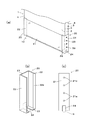
図1および図2に示した扉ガード部材10は、上述したように、表裏2枚のパネル11、11と、2つの端部部材20、20とよりなる。パネル11は、引戸用の扉1の見付け面の両面に取り付けられる。端部部材20は、図1(a)に示すように、扉1の両方の側端の下部に対して、表裏面の面材2に取り付けたパネル11の側端と、角部4、4と、木口面3とを覆うように取り付けられる。   As described above, the door guard member 10 shown in FIGS. 1 and 2 includes two panels 11 and 11 and two end members 20 and 20. The panel 11 is attached to both sides of the finding surface of the door 1 for sliding doors. As shown in FIG. 1 (a), the end member 20 has a side end of the panel 11 attached to the face material 2 on the front and back surfaces, and corners 4, 4 with respect to the lower portions of both side ends of the door 1. Are attached so as to cover the end face 3.

端部部材20は、合成樹脂または金属などを素材とした薄板状の溝形体とされる。端部部材20は、木口面3に接するように配される基部21と、基部21の両方の側端から略平行に延びた延出部22、22とを備えている。基部21と、延出部22、22との間の出隅部はアール加工されている。端部部材20の高さ寸法は、パネル11の縦寸法に概ね相当し、パネル11の両側端の縦方向の全長を覆うことができるように、パネル11の縦寸法よりもやや大きくしてもよい。   The end member 20 is a thin plate-like groove shape made of synthetic resin or metal. The end member 20 includes a base portion 21 disposed so as to be in contact with the end face 3, and extending portions 22, 22 extending substantially in parallel from both side ends of the base portion 21. The protruding corner portion between the base portion 21 and the extending portions 22 and 22 is rounded. The height dimension of the end member 20 substantially corresponds to the vertical dimension of the panel 11 and may be slightly larger than the vertical dimension of the panel 11 so as to cover the entire length in the vertical direction of both side ends of the panel 11. Good.

端部部材20の少なくとも基部21は、扉1の納まりに影響を及ぼさないように、より薄く(たとえば2mm以下に)形成することが望ましいが、納まりに影響する場合には、扉1の取付部位を削るようにしてもよい。なお、他の実施形態を含む各図においては、図示および説明の都合上、やや厚めのものが図示してある。   At least the base portion 21 of the end member 20 is desirably formed thinner (for example, 2 mm or less) so as not to affect the accommodation of the door 1. You may make it sharpen. In each drawing including other embodiments, a slightly thicker one is shown for the sake of illustration and explanation.

基部21には、端部部材20を扉1の木口面3にビス33(図2参照)で固定するための複数のビス挿通孔21a、21a、21aが等間隔で開設されている(図1(b)参照)。基部21の内側の幅寸法(内寸法)は、表裏にパネル11、11を貼り付けた状態の扉1の厚みとほぼ同じか、やや大きければよい。なお、この端部部材20は上下反転させても利用され得る。   A plurality of screw insertion holes 21 a, 21 a, 21 a for fixing the end member 20 to the mouth end surface 3 of the door 1 with screws 33 (see FIG. 2) are formed in the base portion 21 at equal intervals (FIG. 1). (See (b)). The inner width dimension (inner dimension) of the base portion 21 may be substantially the same as or slightly larger than the thickness of the door 1 in a state where the panels 11 and 11 are attached to the front and back surfaces. The end member 20 can be used even if it is turned upside down.

この端部部材20の延出部22、22は、図1(b)、(c)に示すように、内側に段部が形成されて先端側が基部側よりも薄く形成されている。この薄板部22bによって、端部部材20を扉1に取り付けたときに、表裏において、延出部22と面材2との間にパネル11の厚みと同じか、それよりもやや大きい寸法の収容部31が形成される。なお、延出部22には段部が形成されていなくてもよく、図2(a)に示すように、少なくとも
面材2との間にパネル11を配するための収容部31ができるようなものであればよい。このような形状の端部部材20の溝形体は、押出成型にて簡易に成形することができる。
As shown in FIGS. 1B and 1C, the extended portions 22 and 22 of the end member 20 are formed with a stepped portion on the inner side, and the tip side is formed thinner than the base side. When the end member 20 is attached to the door 1 by the thin plate portion 22b, the front and back surfaces of the panel 11 are between the extension portion 22 and the face material 2 and have a size slightly larger than that of the panel 11. Part 31 is formed. It should be noted that the extending portion 22 does not have to be formed with a stepped portion, and as shown in FIG. 2A, an accommodating portion 31 for arranging the panel 11 at least between the face material 2 can be formed. Anything is acceptable. The groove shape of the end member 20 having such a shape can be easily formed by extrusion molding.

本実施形態の扉ガード部材10は、図2(a)〜(c)に示すように、まず端部部材20が扉1に取り付けられ、その後、パネル11が取り付けられるようになっている。以下、この取付手順に沿って扉ガード部材10の取付状態を説明する。   As shown in FIGS. 2A to 2C, the door guard member 10 of the present embodiment is configured such that the end member 20 is first attached to the door 1 and then the panel 11 is attached. Hereinafter, the attachment state of the door guard member 10 is demonstrated along this attachment procedure.

まず、2つの端部部材20、20が扉1の側端に装着され、基部21と木口面3とをビス33で固定することで扉1に固定される。このように端部部材20を取り付けることで、表裏において、端部部材20の延出部22と面材2との間に隙間空間よりなる収容部31が形成される。   First, the two end members 20, 20 are attached to the side ends of the door 1, and are fixed to the door 1 by fixing the base 21 and the end face 3 with screws 33. By attaching the end member 20 in this manner, the accommodating portion 31 formed of a gap space is formed between the extended portion 22 of the end member 20 and the face material 2 on the front and back sides.

図2(b)に示すように、その収容部31にパネル11が上方より挿入される。このパネル11の裏面の上下には予め、透明度の高い両面テープ(不図示)を取り付けておくことが望ましい。そしてパネル11が挿入され、所定の位置に収容され面材2に固着された状態で、両端部部材20、20の両延出部22、22の外面の適所においてビス止めすることで、扉ガード部材10は2種の部材を含む全体が扉1に固定される(図2(c)参照)。なお、両面テープの代わりに透明性の高い接着剤を用いてもよい。また、延出部22の薄板部22bでの固定には、美感を考慮して、ビス33に代えて細釘を用いてもよい。   As shown in FIG. 2B, the panel 11 is inserted into the housing portion 31 from above. It is desirable to attach a highly transparent double-sided tape (not shown) in advance to the upper and lower sides of the back surface of the panel 11. Then, with the panel 11 inserted, housed in a predetermined position and fixed to the face material 2, the door guard is secured by screwing at appropriate positions on the outer surfaces of the extended portions 22, 22 of the both end members 20, 20. The entire member 10 including two types of members is fixed to the door 1 (see FIG. 2C). Note that a highly transparent adhesive may be used instead of the double-sided tape. In addition, in order to fix the extension portion 22 at the thin plate portion 22b, a thin nail may be used instead of the screw 33 in consideration of aesthetics.

このような手順で扉ガード部材10は扉1に固定される。取付手順としては上述したものには限られず、パネル11を面材2に貼り付けてから端部部材20を取り付ける手順であってもよい。また、一方の端部部材20、パネル11、11、他方の端部部材20の順で取り付けるようにしてもよい。ようするに、2種の複数の部材はどのような順序でも取り付けることができる。   The door guard member 10 is fixed to the door 1 by such a procedure. The attachment procedure is not limited to that described above, and may be a procedure for attaching the end member 20 after the panel 11 is attached to the face material 2. Alternatively, the one end member 20, the panels 11, 11, and the other end member 20 may be attached in this order. Thus, the two types of members can be attached in any order.

このように扉ガード部材10は扉1の下部の全周に取り付けられるので、面材2のみならず、木口面3および角部4、4をも保護でき、扉1の下部が損傷したり汚れが付着したりすることを防止することができる。特に、角部4は端部部材20の入隅部でしっかりと保護される。この扉ガード部材10は、病院などの医療施設や高齢者施設、一般住宅などにおいて、車椅子のフットカバーや歩行器、配膳車、杖、靴などの衝突があったときに有効である。また、面材2には透明なパネル11が貼り付けられるため、面材2の意匠性が損なわれることもない。   Thus, since the door guard member 10 is attached to the entire periphery of the lower part of the door 1, not only the face material 2 but also the front face 3 and the corner parts 4 and 4 can be protected, and the lower part of the door 1 is damaged or dirty. Can be prevented. In particular, the corner 4 is firmly protected at the corner of the end member 20. The door guard member 10 is effective when there is a collision of a wheelchair foot cover, a walker, a wheelchair, a cane, shoes, etc. in a medical facility such as a hospital, an elderly facility, or a general house. Moreover, since the transparent panel 11 is affixed on the face material 2, the design property of the face material 2 is not impaired.

また、パネル11は上下が扉1に固着され、両側端が端部部材20、20で保持されるので、パネル11に対して擦れるような衝突があってもずれにくく、正しく取り付けた状態で長期間使用することができる。   Further, since the upper and lower sides of the panel 11 are fixed to the door 1 and both side ends are held by the end members 20 and 20, even if there is a collision that rubs against the panel 11, it is difficult to be displaced, and the panel 11 is long when attached correctly. Can be used for a period.

このように、この扉ガード部材10によれば、扉1の所定の位置への取り付けがしやすく、取付作業を迅速にたやすく行うことができる。また、上述したように、2種の複数の部材をどのような順序でも取り付けることができる構成であるため、手順誤りは発生しにくく、取付作業をするうえでの利便性はきわめて高い。   Thus, according to this door guard member 10, it is easy to attach the door 1 to a predetermined position, and the attaching operation can be performed quickly and easily. Moreover, since it is the structure which can attach two types of several members in what order as mentioned above, a procedure error does not generate | occur | produce easily and the convenience at the time of attachment work is very high.

さらに、パネル11は端部部材20と一体的に扉1にビス止めされるので、両面テープや接着剤で貼り付けなくても扉1に固着することができる。パネル11と面材2との間にごみやほこりが入らないように、少なくとも上部では両面テープなどでパネル11を面材2に固着することが望ましい。   Furthermore, since the panel 11 is screwed to the door 1 integrally with the end member 20, it can be fixed to the door 1 without being attached with a double-sided tape or an adhesive. In order to prevent dust and dust from entering between the panel 11 and the face material 2, it is desirable to fix the panel 11 to the face material 2 with a double-sided tape or the like at least in the upper part.

なお、収容部31への上方からのパネル11の挿入をしやすくするために、やや硬質の変形しにくいパネル11を用いてもよい。また、柔軟なパネル11を用いる場合、パネル11を上面視で山状に変形させて、その左右端部を収容部31に対して、図3(b)の塗りつぶし矢印で示すように、中央から両側端の方向へ挿入することもできる。   In addition, in order to make it easy to insert the panel 11 into the housing portion 31 from above, the panel 11 that is slightly hard and hardly deformed may be used. Further, when the flexible panel 11 is used, the panel 11 is deformed into a mountain shape when viewed from above, and the left and right end portions thereof from the center as shown by the solid arrows in FIG. It can also be inserted in the direction of both ends.

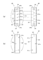
図3および図4に示した扉ガード部材10は、図1に示したものと同様に、表裏2枚のパネル11、11と、2つの端部部材20、20とよりなる。パネル11は引戸用の扉1の見付け面の両面に取り付けられる。端部部材20は、図3(a)に示すように、扉1の両方の側端の下部に対して、表裏面の面材2に取り付けたパネル11の側端と、角部4、4と、木口面3とを覆うように取り付けられる。   The door guard member 10 shown in FIG. 3 and FIG. 4 is composed of two panels 11 and 11 and two end members 20 and 20 as in the case shown in FIG. The panel 11 is attached to both sides of the finding surface of the door 1 for sliding doors. As shown in FIG. 3 (a), the end member 20 has a side end of the panel 11 attached to the face material 2 on the front and back sides and corners 4, 4 with respect to the lower portions of both side ends of the door 1. Are attached so as to cover the end face 3.

端部部材20は、合成樹脂または金属などを素材とした薄板状の溝形体とされる。端部部材20は、木口面3に接するように配される基部21と、基部21の幅方向の両端から略同方向に延びた延出部22、22とを備え、さらに下端(溝端)には扉1の底面が当接する底部23を備えている。端部部材20の高さ寸法は、パネル11の縦寸法に概ね相当し、パネル11の両側端の縦方向の全長を覆うことができるように、パネル11の縦寸法よりも大きくしてもよい。   The end member 20 is a thin plate-like groove shape made of synthetic resin or metal. The end member 20 includes a base 21 disposed so as to be in contact with the end face 3, and extending portions 22 and 22 extending in substantially the same direction from both ends of the base 21 in the width direction, and further at a lower end (groove end). Comprises a bottom 23 against which the bottom of the door 1 abuts. The height dimension of the end member 20 substantially corresponds to the vertical dimension of the panel 11 and may be larger than the vertical dimension of the panel 11 so as to cover the entire length in the vertical direction of both side ends of the panel 11. .

端部部材20の少なくとも基部21は、扉1の納まりに影響を及ぼさないように、より薄く形成することが望ましいが、納まりに影響する場合には、扉1の取付部位を削るようにしてもよい。   At least the base 21 of the end member 20 is desirably formed to be thinner so as not to affect the accommodation of the door 1. However, if the accommodation is affected, the attachment portion of the door 1 may be scraped. Good.

基部21には、端部部材20を扉1の木口面3にビス33で固定するための複数のビス挿通孔21a、21a、・・・が等間隔で開設されている(図3(c)参照)。基部21の内側の幅寸法(内寸法)は、表裏にパネル11、11を貼り付けた状態の扉1の厚みとほぼ同じか、やや大きければよい。   A plurality of screw insertion holes 21a, 21a,... For fixing the end member 20 to the mouth end surface 3 of the door 1 with screws 33 are formed in the base portion 21 at equal intervals (FIG. 3C). reference). The inner width dimension (inner dimension) of the base portion 21 may be substantially the same as or slightly larger than the thickness of the door 1 in a state where the panels 11 and 11 are attached to the front and back surfaces.

両延出部22、22は、扉1の表裏両面の面材2に貼り付けたパネル11に接するように配される部位である。両延出部22、22は、平面視で、先端が相互に近づくようにややすぼんだ形状であり、その先端部の内側には、相互にやや開いた装着ガイド面22aが長手方向の全長にわたって形成されている(図3(b)、図4(a)参照)。   Both extending portions 22 and 22 are portions arranged so as to be in contact with the panel 11 attached to the face material 2 on both the front and back surfaces of the door 1. The two extending portions 22, 22 have a slightly concave shape so that the tips approach each other in a plan view, and the mounting guide surfaces 22 a that are slightly open to each other extend over the entire length in the longitudinal direction. It is formed (see FIGS. 3B and 4A).

また、底部23および基部21の下端部における延出部22、22間の中央位置に、底部23、基部21間で連通する切欠き24が形成されている(図3(b)参照)。この切欠き24は、引戸を走行させるための戸車9あるいはガイドピンなどの案内部材に対応した部位に設けられたものであり、戸車9や案内部材との接触を回避するために形成されている。なお、案内部材などとの接触のおそれがない扉1については、切欠き24のない端部部材20を用いてもよい。   Moreover, the notch 24 connected between the bottom part 23 and the base part 21 is formed in the center position between the extension parts 22 and 22 in the bottom part 23 and the lower end part of the base part 21 (refer FIG.3 (b)). This notch 24 is provided in a portion corresponding to a guide member such as a door wheel 9 or a guide pin for running the sliding door, and is formed to avoid contact with the door wheel 9 or the guide member. . In addition, about the door 1 without a possibility of contact with a guide member etc., you may use the edge part member 20 without the notch 24. FIG.

以下、この扉ガード部材10の扉1に対する取り付けについて、図4(a)、(b)に示した取付手順に沿って説明する。   Hereinafter, the attachment of the door guard member 10 to the door 1 will be described along the attachment procedure shown in FIGS.

まず、パネル11、11が扉1の表裏の面材2、2の表面に取り付けられる。パネル11は、その上下を透明度の高い両面テープ(不図示)で貼り付けられる。なお、パネル11の左右の両側端も扉1に固着してもよい。この両側端の部位は端部部材20が装着されると延出部22によって隠される部位であるため、透明性のない接着剤や両面テープを用いて貼り付けてもよい。また、パネル11の両側端の部位は端部部材20で保持(固定)する部位であるため、パネル11の面材2への固着は端部部材20を取り付けしやすくするための仮止め程度のものであってもよい。   First, the panels 11 and 11 are attached to the surfaces of the front and back face materials 2 and 2 of the door 1. The upper and lower sides of the panel 11 are attached with a highly transparent double-sided tape (not shown). Note that the left and right ends of the panel 11 may also be fixed to the door 1. Since the both end portions are concealed by the extending portion 22 when the end member 20 is attached, the both end portions may be attached using a non-transparent adhesive or double-sided tape. Moreover, since the site | part of the both ends of the panel 11 is a site | part hold | maintained (fixed) by the edge part member 20, the adhering to the face material 2 of the panel 11 is about a temporary stop for making it easy to attach the edge member 20. It may be a thing.

パネル11、11が扉1の両面に取り付けられたのち、端部部材20が扉1の側端に取り付けられる。端部部材20は、延出部22の装着ガイド面22aを扉1の角部4に擦らせるように側方よりスライドするように装着すればよい。このスライド操作を進めると、延出部22、22は相互に離れるように弾性的に拡開しながら、パネル11の表面を中央方向に向かい移動していき、基部21が木口面3に当たって端部部材20は所定の位置に納まる。この状態では、延出部22、22の先端は弾性復帰力により扉1の両面よりパネル11、11を押圧する。なお、端部部材20は延出部22、22を手で拡げながら側端に取り付けるようにしてもよい。   After the panels 11 and 11 are attached to both sides of the door 1, the end member 20 is attached to the side end of the door 1. The end member 20 may be mounted so as to slide from the side so that the mounting guide surface 22a of the extending portion 22 is rubbed against the corner 4 of the door 1. When this sliding operation is advanced, the extending portions 22 and 22 are elastically expanded so as to be separated from each other while moving the surface of the panel 11 toward the center, and the base portion 21 hits the end face 3 and ends. The member 20 is stored in a predetermined position. In this state, the ends of the extending portions 22 and 22 press the panels 11 and 11 from both surfaces of the door 1 by elastic return force. The end member 20 may be attached to the side end while extending the extension portions 22 and 22 by hand.

こうして、端部部材20は、底部23の内底面が扉1の底面に接した状態で側端に装着される。そしてその後、基部21を木口面3にビス止めすることで、表裏のパネル11、11および両端部部材20、20は扉1に固定される。   Thus, the end member 20 is attached to the side end with the inner bottom surface of the bottom portion 23 in contact with the bottom surface of the door 1. Then, the front and back panels 11 and 11 and the both end members 20 and 20 are fixed to the door 1 by screwing the base 21 to the end face 3.

このようにこの扉ガード部材10は、図1に示したものと同様に、扉1の下部の全周に取り付けられるので、面材2のみならず、木口面3および角部4をも保護でき、扉1の下部が損傷したり汚れが付着したりすることを防止することができる。特に、角部4は端部部材20の入隅部でしっかりと保護される。この扉ガード部材10は、病院などの医療施設や高齢者施設、一般住宅などにおける車椅子のフットカバーや歩行器、配膳車、杖、靴などの衝突があったときに有効である。また、面材2には透明なパネル11が貼り付けられるため、面材2の意匠性が損なわれることもない。   As described above, the door guard member 10 is attached to the entire periphery of the lower portion of the door 1 in the same manner as shown in FIG. 1, so that not only the face material 2 but also the end face 3 and the corner 4 can be protected. The lower part of the door 1 can be prevented from being damaged or soiled. In particular, the corner 4 is firmly protected at the corner of the end member 20. This door guard member 10 is effective when there is a collision between a wheelchair foot cover, a walker, a wheelchair, a walking stick, shoes, etc. in a medical facility such as a hospital, an elderly facility, or a general house. Moreover, since the transparent panel 11 is affixed on the face material 2, the design property of the face material 2 is not impaired.

また、パネル11は上下が扉1に固着され、両側端が端部部材20、20で保持されるので、パネル11に対して擦れるような衝突があってもずれにくく、長期間使用することができる。特に、本図例のものは端部部材20の延出部22、22の弾性力でパネル11を押圧保持するようになっているため、延出部22へのビス止めがなくてもパネル11のずれ、外れを防止することができる。延出部22が弾性力にてパネル11を強く押圧できるものであれば、端部部材20自体も、扉1を強固に挟みこむように扉1に固定される。このように延出部22へのビス止めがなくてもよいため、美感が損なわれることもない。   In addition, since the panel 11 is fixed to the door 1 at the top and bottom, and both end portions are held by the end members 20 and 20, even if there is a collision that rubs against the panel 11, the panel 11 can be used for a long time. it can. In particular, in the illustrated example, the panel 11 is pressed and held by the elastic force of the extending portions 22 and 22 of the end member 20, so that the panel 11 does not need to be screwed to the extending portion 22. Slippage and disconnection can be prevented. If the extension part 22 can press the panel 11 strongly with an elastic force, the end member 20 itself is also fixed to the door 1 so as to sandwich the door 1 firmly. Since there is no need to fix the screws to the extending portion 22 in this way, the aesthetics are not impaired.

さらに、本実施形態の端部部材20は底部23を有しているため、頑丈な構造となっており、扉1に取り付けるまでの取り扱いにおいて、基部21や延出部22、22が破損することを防止することができる。また、端部部材20の扉1への取り付けに際して位置合わせが容易にできるため、取り付けがしやすい。   Furthermore, since the end member 20 of this embodiment has the bottom part 23, it has a sturdy structure, and the base part 21 and the extension parts 22 and 22 are damaged in handling until it is attached to the door 1. Can be prevented. Further, since the positioning can be easily performed when the end member 20 is attached to the door 1, the attachment is easy.

つぎに、図5に示した扉ガード部材10について説明する。この扉ガード部材10も、パネル11と、端部部材20とよりなり、図1のものと同様、扉1の下部の全周に取り付けられる。   Next, the door guard member 10 shown in FIG. 5 will be described. This door guard member 10 also includes a panel 11 and an end member 20, and is attached to the entire periphery of the lower portion of the door 1 as in the case of FIG.

端部部材20は溝形体ではあるが、図1のものとは異なり底部23を有している。底部23から基部21にかけて、切欠き24が形成されている。この端部部材20の延出部22、22は、図1のものと同様に、内側に段部が形成されて先端側が基部側よりも薄く形成されている。この薄板部22bによって、端部部材20を扉1に取り付けたときに、表裏において、延出部22と面材2との間にパネル11の厚みと同じか、それよりもやや大きい寸法の収容部31が形成される。なお、延出部22には段部が形成されていなくてもよく、図5(a)に示すように、少なくとも面材2との間にパネル11を配するための収容部31ができるようなものであればよい。   The end member 20 has a groove shape, but has a bottom 23 unlike that of FIG. A notch 24 is formed from the bottom 23 to the base 21. As in the case of FIG. 1, the extended portions 22, 22 of the end member 20 are formed with a stepped portion on the inner side, and the tip side is formed thinner than the base side. When the end member 20 is attached to the door 1 by the thin plate portion 22b, the front and back surfaces of the panel 11 are between the extension portion 22 and the face material 2 and have a size slightly larger than that of the panel 11. Part 31 is formed. It should be noted that the extending portion 22 does not have to be formed with a stepped portion, and as shown in FIG. 5A, an accommodating portion 31 for arranging the panel 11 at least between the face material 2 can be formed. Anything is acceptable.

本実施形態の扉ガード部材10は、図5(a)〜(c)に示すように、まず端部部材20が扉1に取り付けられ、その後、パネル11が取り付けられるようになっている。以下、この取付手順に沿って取付状態を説明する。   As shown in FIGS. 5A to 5C, the door guard member 10 of the present embodiment is configured such that the end member 20 is first attached to the door 1 and then the panel 11 is attached. Hereinafter, an attachment state is demonstrated along this attachment procedure.

まず、2つの端部部材20、20が、底部23が扉1の底面に接する状態で側端に装着される。その後、基部21と木口面3とをビス33で固定することで、端部部材20は扉1に固定される。このように端部部材20を取り付けることで、端部部材20の延出部22と面材2との間に隙間空間よりなる収容部31が形成される。   First, the two end members 20, 20 are attached to the side ends with the bottom 23 contacting the bottom surface of the door 1. Then, the end member 20 is fixed to the door 1 by fixing the base 21 and the end face 3 with screws 33. By attaching the end member 20 in this way, the accommodating portion 31 formed of a gap space is formed between the extending portion 22 of the end member 20 and the face material 2.

図5(b)に示すように、その収容部31にパネル11が上方より挿入されると、パネル11は端部部材20の底部23に下方より支持された状態となる。そして、パネル11は、両端部部材20、20の両延出部22、22の外面の適所において扉1に対してビス止めすることで固定される(図5(c)参照)。   As shown in FIG. 5B, when the panel 11 is inserted into the housing portion 31 from above, the panel 11 is supported by the bottom 23 of the end member 20 from below. And the panel 11 is fixed by screwing with respect to the door 1 in the appropriate place of the outer surface of both the extension parts 22 and 22 of the both-ends members 20 and 20 (refer FIG.5 (c)).

このように、この扉ガード部材10によれば、図1に示したものと同様に、パネル11は両面テープや接着剤で貼り付けなくても扉1に取り付けることができる。特に、パネル11は端部部材20の底部23で位置決めされ、支持されるので、面材2に固着されなくてもよく、パネル11の取付作業を迅速にたやすく行うことができる。また、パネル11と面材2との間にごみやほこりが入らないように、上部では両面テープなどでパネル11を面材2に固着することが望ましい。   As described above, according to the door guard member 10, the panel 11 can be attached to the door 1 without being attached with a double-sided tape or an adhesive as in the case shown in FIG. In particular, since the panel 11 is positioned and supported by the bottom 23 of the end member 20, the panel 11 does not have to be fixed to the face material 2, and the panel 11 can be attached quickly and easily. Further, it is desirable that the panel 11 is fixed to the face material 2 with a double-sided tape or the like at the upper part so that dust and dust do not enter between the panel 11 and the face material 2.

なお、収容部31への上方からのパネル11の挿入をしやすくするために、やや硬質の変形しにくいパネル11を用いてもよい。また、柔軟なパネル11を用いる場合、パネル11を上面視で山状に変形させて、その左右端部を収容部31に対して、図5(b)の塗りつぶし矢印で示すように、中央から両側端の方向へ挿入するようにしてもよい。   In addition, in order to make it easy to insert the panel 11 into the housing portion 31 from above, the panel 11 that is slightly hard and hardly deformed may be used. Further, when the flexible panel 11 is used, the panel 11 is deformed into a mountain shape when viewed from above, and the left and right end portions thereof from the center as shown by the solid arrows in FIG. You may make it insert in the direction of a both-sides end.

ついで、図6(a)、(b)に示した扉ガード部材(本図には端部部材20のみを図示)の端部部材20について説明する。これらの端部部材20、20はいずれも、図1に示したものと同様、上下反転させても扉1に取り付けできるものである。また、これらの端部部材20、20には底部23(図3(b)等を参照)が形成されておらず、基部21と両延出部22、22とを備えた構成となっている。   Next, the end member 20 of the door guard member shown in FIGS. 6A and 6B (only the end member 20 is shown in the figure) will be described. These end members 20 and 20 can be attached to the door 1 even if they are turned upside down, similar to the one shown in FIG. Further, these end members 20, 20 are not formed with a bottom 23 (see FIG. 3B, etc.), and have a base 21 and both extending portions 22, 22. .

図6(a)に示した端部部材20の基部21の上下端には、案内部材や戸車9(図3(c)参照)との接触を避けるための切欠き24、24が形成されている。   Notches 24 and 24 are formed on the upper and lower ends of the base portion 21 of the end member 20 shown in FIG. 6A to avoid contact with the guide member and the door wheel 9 (see FIG. 3C). Yes.

また、基部21には複数のビス挿通孔21a、21a、・・・が等間隔に形成されている。図6(a)の左図に示すように、上部の切欠き24の縁部24aから最上部のビス挿通孔21aまでの距離L1は、下部の切欠き24の縁部24aから最下部のビス挿通孔21aまでの距離L2と異なる。すなわち、図6(a)に示すように端部部材20を上下反転させて右図のようにすれば、4つのビス挿通孔21aの高さ位置は元の位置よりも全体的に低くなる。   Further, the base portion 21 is formed with a plurality of screw insertion holes 21a, 21a,. 6A, the distance L1 from the edge 24a of the upper notch 24 to the uppermost screw insertion hole 21a is the same as that of the lowermost screw 24 from the edge 24a of the lower notch 24. It is different from the distance L2 to the insertion hole 21a. That is, as shown in FIG. 6A, if the end member 20 is turned upside down as shown in the right figure, the height positions of the four screw insertion holes 21a are generally lower than the original positions.

このように上下反転させたときにビス挿通孔21aの位置が変化するので、パネル11だけを取り替える場合など、端部部材20を取り外して再度取り付ける場合に、木口面3(図1(a)参照)の元のビス穴にビス止めしなくてもよい。つまり、上下反転させて再取り付けする場合、木口面3の新たな位置にビス33を打ち込むことができる。よって、再取り付けの場合でも、端部部材20をしっかりと扉1(図1(a)参照)に固定することができる。   Since the position of the screw insertion hole 21a changes when it is turned upside down in this way, when the end member 20 is removed and reattached, such as when only the panel 11 is replaced, the end face 3 (see FIG. 1 (a)). ) Does not need to be screwed into the original screw hole. That is, when reattaching by turning upside down, the screw 33 can be driven into a new position on the end face 3. Therefore, even in the case of reattachment, the end member 20 can be firmly fixed to the door 1 (see FIG. 1A).

図6(b)に示した端部部材20は、複数(奇数)のビス挿通孔21aが基部21に千鳥状に形成してある。この図例のものは、図6(b)の左図に示すように、この端部部材20の基部21にはビス挿通孔21aは3つあり、そのうちの中央のものが左側に、上下2つのものが右側に形成してある。   In the end member 20 shown in FIG. 6B, a plurality (odd number) of screw insertion holes 21 a are formed in a staggered manner in the base portion 21. In this example, as shown in the left diagram of FIG. 6 (b), the base 21 of the end member 20 has three screw insertion holes 21a, of which the middle one is on the left side and the top and bottom 2 One is formed on the right side.

この端部部材20は、図6(b)に示す端部部材20を上下反転させて右図のようにすれば、ビス挿通孔21aはそれぞれが反対の位置に移動する。つまり、上下反転させたときには、中央のビス挿通孔21aは右側に、上下2つのビス挿通孔21aは上下が反転して左側に配せられる。   When the end member 20 is turned upside down as shown in the right figure of the end member 20 shown in FIG. 6B, the screw insertion holes 21a are moved to opposite positions. That is, when reversed upside down, the central screw insertion hole 21a is arranged on the right side, and the two upper and lower screw insertion holes 21a are arranged upside down on the left side.

このように、この端部部材20についても上下反転させたときにビス挿通孔21aの位置が変化するので、端部部材20を再取り付けする場合に、木口面3(図1(a)参照)の元のビス穴にビス止めしなくてもよい。つまり、上下反転させて再取り付けする場合、木口面3の新たな位置にビス33を打ち込むことができる。よって、再取り付けした場合でも、端部部材20をしっかりと扉1(図1(a)参照)に固定することができる。   Thus, when the end member 20 is also turned upside down, the position of the screw insertion hole 21a changes. Therefore, when the end member 20 is reinstalled, the end face 3 (see FIG. 1A). It is not necessary to screw in the original screw hole. That is, when reattaching by turning upside down, the screw 33 can be driven into a new position on the end face 3. Therefore, even when reattached, the end member 20 can be firmly fixed to the door 1 (see FIG. 1A).

また、図6(a)、(b)に示した2種の端部部材20、20は底部23(図1(b)参照)を有しない形状であるため、押出成型にて簡易に製造することができる。もちろん、これらの端部部材20、20は底部23を有してもよく、底部23側の端部を上に配するように上下反転させて使用する際に、その底部23を切除して使用するようにしてもよい。また、これらの端部部材20、20は、図3に示した端部部材20と同様に、扉1(図3(a)参照)の側端に対して弾性嵌合する構造であってもよい。   Moreover, since the two types of end members 20 and 20 shown in FIGS. 6A and 6B do not have the bottom 23 (see FIG. 1B), they are easily manufactured by extrusion molding. be able to. Of course, these end members 20, 20 may have a bottom 23, and the bottom 23 is cut off when used with the end on the bottom 23 side upside down. You may make it do. Moreover, these end members 20 and 20 may be elastically fitted to the side edges of the door 1 (see FIG. 3A), similarly to the end member 20 shown in FIG. Good.

上下反転させて取り付ける際にビス穴の位置が変化する端部部材20として、図6(a)、(b)のものを例示したが、上下反転させたときにビス挿通孔21aの位置が変化するものであれば、その他の配置のものであってもよい。   6 (a) and 6 (b) are illustrated as the end member 20 in which the position of the screw hole changes when it is turned upside down, but the position of the screw insertion hole 21a changes when turned upside down. Other arrangements may be used as long as they do.

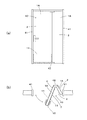
つぎに、図7に示した扉ガード部材10について説明する。図7に示した端部部材20は平面視でL字形をなしている。つまり、端部部材20は、木口面3の幅方向の約半分を覆う基部21と、その側端から扉1の面に沿うように延びた延出部22とを備えている。なお、この端部部材20は底部23(図3(b)参照)を有していないが、有したものとしてもよい。   Next, the door guard member 10 shown in FIG. 7 will be described. The end member 20 shown in FIG. 7 has an L shape in plan view. That is, the end member 20 includes a base portion 21 that covers about half of the width direction of the end surface 3 and an extending portion 22 that extends from the side end along the surface of the door 1. The end member 20 does not have the bottom 23 (see FIG. 3B), but may have it.

この端部部材20によれば、1つの部材で、面材2の側端と、角部4と、それに連なる木口面3の幅方向(見込み方向)の約半分とを覆うことができるようになっている。ようするに、扉1の一側端において、木口面3の全体を保護し、かつ表裏のパネル11、11を保持するために、1組の端部部材20、20が必要とされる。   According to this end member 20, one member can cover the side end of the face material 2, the corner portion 4, and about half of the width direction (expected direction) of the end face 3 connected thereto. It has become. Thus, at one side end of the door 1, a pair of end members 20, 20 are required to protect the entire facet 3 and hold the front and back panels 11, 11.

この端部部材20は、パネル11が面材2に貼り付けられたのち、角部4にあてがわれ、延出部22の適所においてビス止めされて固定される。扉1の一側端に2つの端部部材20、20が取り付けられると、両部材の基部21、21間には上下に沿った溝状の空間ができる。この空間は、下部において、戸車9(図3(c)参照)や案内部材との接触を回避するための空間である。なお、このような空間ができないものであってもよい。   After the panel 11 is attached to the face material 2, the end member 20 is applied to the corner portion 4, and is screwed and fixed at an appropriate position of the extension portion 22. When the two end members 20, 20 are attached to one side end of the door 1, a groove-like space along the top and bottom is formed between the base portions 21, 21 of both members. This space is a space for avoiding contact with the door wheel 9 (see FIG. 3C) and the guide member in the lower part. Note that such a space may not be possible.

この図例で示した、一方の側端の表裏で使用する1組の端部部材20、20は、図7(a)に示すように高さ寸法が相互に同一であり、かつ図7(b)に示すように平面視で対称形状である。したがって、たがいに同形状の1種の端部部材20を複数準備しておけば、上下反転させていずれにも使用することができる。   As shown in FIG. 7A, the pair of end members 20 and 20 used on the front and back of one side end shown in this example have the same height dimension, and FIG. As shown in b), it is symmetrical in plan view. Therefore, if a plurality of end members 20 having the same shape are prepared, they can be used upside down.

このように、本実施形態の端部部材20によれば、1種の端部部材20で表裏両方に利用できるので、在庫管理の面で利便性が高い。また、表裏の一方の面のみにパネル11を取り付ける場合に、表面側の端部部材20のみで足りるので、部材(材料)の節約に貢献できる。また、底部23がないので押出成型により簡易に製造することができる。   As described above, according to the end member 20 of the present embodiment, the one type of end member 20 can be used for both the front and the back, which is highly convenient in terms of inventory management. Further, when the panel 11 is attached only to one surface of the front and back surfaces, only the end member 20 on the front surface side is sufficient, which can contribute to saving of members (materials). Moreover, since there is no bottom part 23, it can manufacture simply by extrusion molding.

また、1つの端部部材20で木口面3の幅方向(見込み方向)の全体を保護できるように、木口面3の幅寸法に対応した基部21を有したL字状の部材であってもよい。パネル11の取り付けが表裏の一方のみに対してであり、かつ木口面3および2つの角部4を保護する必要があるような場合に、このような端部部材20を好適に使用することができる。   Moreover, even if it is the L-shaped member which has the base 21 corresponding to the width dimension of the end face 3 so that the whole width direction (expected direction) of the end face 3 can be protected with one end member 20. Good. Such an end member 20 can be preferably used when the panel 11 is attached to only one of the front and back sides and the end face 3 and the two corners 4 need to be protected. it can.

つぎに、図8〜図10にもとづいて、折戸に取り付けられる扉ガード部材10について説明する。本実施形態の折戸40は、図8(a)、(b)に示すように、2枚1組の戸体1A、1Aを相互に回動可能に連結させてドア枠に取り付けてなる間仕切り用の折戸ドアである。この折戸ドアは、たとえば高齢者施設や車椅子用の公衆トイレなどに使用される。   Next, the door guard member 10 attached to the folding door will be described with reference to FIGS. As shown in FIGS. 8 (a) and 8 (b), the folding door 40 of the present embodiment is for a partition formed by connecting a pair of door bodies 1A and 1A to each other so as to be pivotable and attached to a door frame. This is a folding door. This folding door is used, for example, in elderly facilities and public toilets for wheelchairs.

この折戸40の幅寸法の小さいほうの戸体1Aは、一方の側端縁が一方(図8の右側)の縦枠41側にヒンジ結合され、他方の側端縁が幅寸法の大きいほうの戸体の一方の側端縁と上下に設けた連結材42にて回動可能に連結されている。連結材42には、相互に噛み合った1組のギア(不図示)が内装されている。   The door body 1A having the smaller width dimension of the folding door 40 has one side end edge hinged to one vertical frame 41 side (the right side in FIG. 8) and the other side end edge having the larger width dimension. It is connected to one side edge of the door body so as to be rotatable by a connecting member 42 provided at the top and bottom. The connecting member 42 includes a set of gears (not shown) that mesh with each other.

幅寸法の大きい戸体1Aの他方の側端縁は開放されており、2枚の戸体1A、1Aの折り畳みにより折戸ドアが開くようになっている。なお、2枚の戸体1A、1Aの相互に連結される各側端縁は、相互に回転しやすいように平面視で湾曲状に(多角形状に)形成されている(図10参照)。   The other side edge of the door body 1A having a large width is opened, and the folding door is opened by folding the two door bodies 1A and 1A. Note that the side edges of the two doors 1A and 1A that are connected to each other are formed in a curved shape (polygonal shape) in plan view so that they can easily rotate with each other (see FIG. 10).

扉ガード部材10は、図8(a)、(b)に2点鎖線で示したように、パネル11が幅寸法の大きい戸体1A(以下、たんに戸体1Aという)の表裏に取り付けられるようになっている。以下、扉ガード部材10を構成する各部材およびその取付態様について説明する。   As shown by a two-dot chain line in FIGS. 8A and 8B, the door guard member 10 is attached to the front and back of the door body 1A having a large width dimension (hereinafter simply referred to as the door body 1A). It is like that. Hereinafter, each member which comprises the door guard member 10, and its attachment aspect are demonstrated.

扉ガード部材10は、戸体1Aの表裏の面材2の表面に取り付ける2枚のパネル11、11と、戸体1Aの開放側の側端縁に取り付ける1組の端部部材20、20とを備えている。扉ガード部材10はさらに、連結部側でパネル11、11の側端をパネル11面に対して押さえ保持する押さえ部材26と、押さえ部材26と隣接する戸体1Aの面との直接的な接触を防止するための緩衝部材28とを備えている。緩衝部材28は、戸体1A、1Aが折り畳まれることで押さえ部材26と対面する戸板1Aとの衝突による損傷を回避するための部材である。   The door guard member 10 includes two panels 11 and 11 that are attached to the front and back surfaces 2 of the door body 1A, and a pair of end members 20 and 20 that are attached to the open side edge of the door body 1A. It has. The door guard member 10 further has a direct contact between the pressing member 26 that holds and holds the side edges of the panels 11 and 11 against the surface of the panel 11 on the connecting portion side, and the surface of the door 1 </ b> A adjacent to the pressing member 26. And a buffer member 28 for preventing the above. The buffer member 28 is a member for avoiding damage due to a collision between the pressing member 26 and the door plate 1A facing the door member 1A, 1A by being folded.

端部部材20は、図7で示したものと同様に、平面視でL字形をなしている。つまり、端部部材20は、木口面3の幅方向の約半分を覆う基部21と、その側端から戸体1Aの面に沿うように延びた延出部22とを備えている(図9(b)参照)。   The end member 20 has an L shape in plan view, similar to that shown in FIG. That is, the end member 20 includes a base portion 21 that covers approximately half of the width direction of the end surface 3 and an extending portion 22 that extends from the side end along the surface of the door 1A (FIG. 9). (See (b)).

それぞれの端部部材20の基部21には、端部部材20を扉1の木口面3にビス33で固定するための複数のビス挿通孔21a、21a、21aが等間隔で開設されている(図9(b)参照)。端部部材20、20間に戸体1Aの木口面3が露出しないように、基部21の内側の幅寸法(内寸法)を扉1の厚みの半分とすることが望ましい。また、図例の端部部材20は上下反転させることでいずれの端部部材20としても利用することができる。   A plurality of screw insertion holes 21 a, 21 a, 21 a for fixing the end member 20 to the front end 3 of the door 1 with screws 33 are formed at equal intervals in the base portion 21 of each end member 20 ( (See FIG. 9B). It is desirable that the width dimension (inner dimension) on the inner side of the base portion 21 is half the thickness of the door 1 so that the end face 20 of the door 1A is not exposed between the end members 20 and 20. Further, the end member 20 in the figure can be used as any end member 20 by being inverted upside down.

また、端部部材20の延出部22は、図9(b)、(c)に示すように、基部21よりも薄く形成されている。この延出部22によって、面材2の表面に取り付けたパネル11を押さえられるようになっている。戸板1Aの面での突出量を小さくするために、延出部22は図例のように薄くすることが望ましい。   Moreover, the extension part 22 of the edge part member 20 is formed thinner than the base part 21, as shown in FIG.9 (b), (c). The panel 11 attached to the surface of the face material 2 can be pressed by the extending portion 22. In order to reduce the amount of protrusion on the surface of the door plate 1A, it is desirable that the extending portion 22 be thin as shown in the figure.

一方、押さえ部材26は、図9(a)、(d)に示すように、パネル11の側端を押さえ付けられるように、その縦寸法は端部部材20とほぼ同一とされ、端部部材20と同一の素材で成形されることが望ましい。   On the other hand, as shown in FIGS. 9A and 9D, the holding member 26 has a vertical dimension substantially the same as that of the end member 20 so that the side end of the panel 11 can be pressed. It is desirable to mold with the same material as 20.

押さえ部材26は概ね平板状に形成されているが、面材2に取り付ける面には段部が形成されて本体部26aよりも薄く形成されている。この薄板部26bは端部部材20の延出部22と同様に、パネル11を押さえて覆い隠すように作用する。一方、本体部26aには複数のビス挿通孔26c、26cが等間隔で開設されている。この押さえ部材26も押出成型にて成形でき、上下反転させることで表裏いずれの押さえ部材26としても利用できるようになっている。   Although the pressing member 26 is formed in a substantially flat plate shape, a step portion is formed on the surface attached to the face material 2 and is formed thinner than the main body portion 26a. The thin plate portion 26b acts to hold down and cover the panel 11 in the same manner as the extended portion 22 of the end member 20. On the other hand, a plurality of screw insertion holes 26c, 26c are opened at equal intervals in the main body portion 26a. The pressing member 26 can also be formed by extrusion molding, and can be used as the pressing member 26 on either the front or back side by turning upside down.

この押さえ部材26は、折戸40においては、上述した実施形態の種々の扉1の両端に取り付ける端部部材20の一方のものに代わる、パネル11の側端を隠すための部材である。連結部における戸体1Aの湾曲形成された側端部には端部部材20を取り付けることができないため、その代わりにパネル11の面材2側において、押さえ部材26がパネル11の側端を隠すように取り付けられる。このように押さえ部材26は端部部材20と類似の目的で使用されるため、端部部材20と同種の素材で成形することが望ましく、両部材間で意匠性を統一することが望ましい。   In the folding door 40, the pressing member 26 is a member for hiding the side end of the panel 11 instead of one of the end members 20 attached to both ends of the various doors 1 of the above-described embodiment. Since the end member 20 cannot be attached to the curved side end portion of the door 1 </ b> A in the connecting portion, the pressing member 26 conceals the side end of the panel 11 on the face material 2 side of the panel 11 instead. It is attached as follows. As described above, since the pressing member 26 is used for a purpose similar to that of the end member 20, it is desirable to form it with the same kind of material as that of the end member 20, and it is desirable to unify the design between both members.

また、押さえ部材26の表面に貼り付ける緩衝部材28としては、柔軟な合成樹脂で成形された、円形や矩形等の粘着剤付きのクッション材(衝撃吸収剤)を用いればよい。緩衝部材28は、それが貼り付けられる押さえ部材26の意匠性や、端部部材20、20、裏面側に取り付ける他の押さえ部材26との総合的な意匠性が損なわれないように、透明材とすることが望ましく、目立たないように1箇所に取り付けることが望ましい。   In addition, as the buffer member 28 to be attached to the surface of the pressing member 26, a cushion material (impact absorber) with an adhesive such as a circle or a rectangle, which is formed of a flexible synthetic resin, may be used. The buffer member 28 is made of a transparent material so that the design of the pressing member 26 to which the buffer member 28 is attached and the overall design of the end members 20, 20 and the other pressing members 26 attached to the rear surface side are not impaired. It is desirable to attach to one place so as not to stand out.

扉ガード部材10を構成するこれらの部材は、図10(a)に示すように取り付けられる。すなわち、まず表裏の各パネル11を上下において両面テープ(不図示)で取り付け、その後、端部部材20、20および押さえ部材26をビス33で固定、取り付けし、さらにその後、緩衝部材28を取り付けるようにすればよい。パネル11は両面テープや接着剤で面材2の表面に貼り付けたうえ、さらに端部部材20や押さえ部材26で側端を保持する(押さえる)ことが望ましいが、パネル11の側端を隠すだけの構成であってもよい。なお、図10(a)では端部部材20を戸板1Aの側方より取り付けるように図示してあるが、パネル11を延出部22で押さえるようにした後、木口面3でビス止めすれば、パネル11を端部部材20でより強固に保持することができる。   These members constituting the door guard member 10 are attached as shown in FIG. That is, first, the front and back panels 11 are attached with a double-sided tape (not shown) at the top and bottom, then the end members 20, 20 and the pressing member 26 are fixed and attached with screws 33, and then the buffer member 28 is attached. You can do it. The panel 11 is preferably affixed to the surface of the face material 2 with a double-sided tape or an adhesive, and the side end is preferably held (pressed) by the end member 20 or the pressing member 26, but the side end of the panel 11 is hidden. Only the structure may be sufficient. In FIG. 10A, the end member 20 is illustrated as being attached from the side of the door plate 1A. However, after the panel 11 is pressed by the extending portion 22, it is screwed at the mouth end surface 3. The panel 11 can be more firmly held by the end member 20.

以上のように、本実施形態に係るパネル11は、折戸40を構成する相互に連結された2枚の戸体1A、1Aのうち少なくとも、一方の側端縁が開放された戸体1Aに取り付けられるようになっている。そして、戸体1Aに取り付けられたパネル11は、戸体1Aの開放された側端縁側に配された側端が端部部材20によって隠される一方、戸体1Aの連結された側端縁側に配された側端が押さえ部材26で隠される構成になっている。   As described above, the panel 11 according to the present embodiment is attached to the door body 1A in which at least one side edge of the two door bodies 1A and 1A constituting the folding door 40 is open. It is supposed to be. The panel 11 attached to the door body 1A is concealed by the end member 20 on the side end edge side of the door body 1A that is opened, and on the side edge side to which the door body 1A is connected. The arranged side ends are hidden by the pressing member 26.

このような扉ガード部材10によれば、折戸ドアの側端縁が開放されているほうの戸体1Aの面材2の下部、木口面3および角部4を、車椅子などの衝突から保護することができる。また、上述した他の実施形態に係るものと同様、パネル11の側端が端部部材20や押さえ部材26によって少なくとも隠される構成となっているので、見栄えもよい。また、これらの部材によってパネル11を保持するようにすれば、パネル11はさらにしっかりと面材2に固定され、長期間にわたって適切な取付状態が維持される。   According to such a door guard member 10, the lower part of the face member 2, the end face 3, and the corner 4 of the door body 1 </ b> A whose side edge of the folding door is open is protected from a collision such as a wheelchair. be able to. Moreover, since it has the structure which the side end of the panel 11 is at least concealed by the edge part member 20 and the pressing member 26 similarly to what concerns on other embodiment mentioned above, it looks good. Moreover, if the panel 11 is hold | maintained by these members, the panel 11 will be fixed more firmly to the face material 2, and a suitable attachment state will be maintained over a long period of time.

また、図10(b)に示すように、折戸40の折り畳みにより幅寸法の小さい戸体1A面に近接するほうの押さえ部材26の表面には緩衝部材28が貼り付けてあるので、押さえ部材26と他方の戸体1Aとの急激な衝突による衝撃を吸収することができる。また、衝突による幅寸法の小さい戸板1Aの面材2の損傷を防止することができる。   Further, as shown in FIG. 10B, since the buffer member 28 is attached to the surface of the pressing member 26 that is closer to the surface of the door body 1A having a smaller width dimension when the folding door 40 is folded, the pressing member 26 is attached. It is possible to absorb an impact caused by a sudden collision between the first door 1A and the other door 1A. Moreover, damage to the face material 2 of the door plate 1A having a small width dimension due to a collision can be prevented.

また、本実施形態の端部部材20や図7に示した端部部材20は、L字形をなし、一対で戸板1Aや扉1の木口面3を覆う構成となっているため、厚さ寸法の大きい扉1や戸板1Aにも対応できる。たとえば図7、図9(b)、図10に示したように、木口面3の中央に隙間ができるが、そのような端部部材20によっても木口面3および角部4を保護することができる。   Moreover, since the end member 20 of this embodiment and the end member 20 shown in FIG. 7 are L-shaped and are configured to cover the door plate 1A and the door end surface 3 of the door 1 as a pair, the thickness dimension The door 1 and the door plate 1A having a large size can be handled. For example, as shown in FIG. 7, FIG. 9B, and FIG. 10, a gap is formed at the center of the end face 3, but such end member 20 can also protect the end face 3 and the corner 4. it can.

さらにまた、端部部材20がL字形であるため、パネル11の厚みに応じた基部21の取付位置の調整をすることができる。つまり、基部21、21間にできる隙間でパネル11の異なる厚みの差を吸収できるようにしてもよい。また、端部部材20がL字形であるため、パネル11を延出部22でしっかりと押さえつけた状態にして端部部材20を強固に固定することができ、その結果、パネル11のずれや外れを生じにくくすることができる。   Furthermore, since the end member 20 is L-shaped, the attachment position of the base 21 can be adjusted according to the thickness of the panel 11. That is, a difference in thickness of the panel 11 may be absorbed by a gap formed between the base portions 21 and 21. Further, since the end member 20 is L-shaped, the end member 20 can be firmly fixed in a state where the panel 11 is firmly pressed by the extending portion 22, and as a result, the panel 11 is displaced or detached. Can be made difficult to occur.

また、L字形の端部部材20であっても、図1に示した端部部材20のように、延出部22の内側に段部を設けて先端側を薄肉としたものでもよい。端部部材20をそのように形成すれば、図2や図5に示したようにパネル11を後付けするともできる。   Moreover, even if it is the L-shaped end member 20, the step part may be provided inside the extension part 22 like the end member 20 shown in FIG. If the end member 20 is formed in such a manner, the panel 11 can be retrofitted as shown in FIGS.

さらに、本実施形態の端部部材20によれば、図7に示したものと同様、1種の端部部材20で表裏両方に利用できるので、在庫管理の面で利便性が高い。また、表裏の一方の面のみにパネル11を取り付ける場合に、いずれか一方の端部部材20のみで足りるので、部材(材料)の節約に貢献できる。また、底部23(図3参照)を有さない形状であるため押出成型により簡易に製造することができる。   Furthermore, according to the end member 20 of the present embodiment, the same kind of end member 20 as shown in FIG. 7 can be used for both front and back, so that it is highly convenient in terms of inventory management. Further, when the panel 11 is attached to only one surface of the front and back, only one of the end members 20 is sufficient, which can contribute to saving of members (materials). Moreover, since it is a shape which does not have the bottom part 23 (refer FIG. 3), it can manufacture easily by extrusion molding.

本実施形態では、折戸ドア用の扉ガード部材10として図8に示したものを例示したが、図1などの他の形状のものを用いてもよい。また、上述した種々の扉ガード部材10は、複数組の折戸40を設けた間仕切り用の折戸ドアにも適用できる。連結された2枚の戸体のいずれもが縦枠41(図8参照)にヒンジ結合されず、縦枠41間を移動する折戸では、扉ガード部材10はいずれの戸体にも取り付けるようにすることが望ましい。   In the present embodiment, the door guard member 10 for a folding door is illustrated in FIG. 8, but other shapes such as FIG. 1 may be used. Moreover, the various door guard member 10 mentioned above is applicable also to the folding door for partitions which provided the multiple sets of folding door 40. FIG. None of the two connected doors are hinged to the vertical frame 41 (see FIG. 8), and the door guard member 10 is attached to any door in the folding door that moves between the vertical frames 41. It is desirable to do.

上述した複数種の端部部材20、20のうち図3、図6(a)、(b)、図8に示したものは、木口面3にビス止めする構成であるため、扉1の表裏面にビス33の頭部が現れず、見映えもよい。   Among the plural types of end members 20, 20 described above, those shown in FIGS. 3, 6 (a), (b), and FIG. The head of the screw 33 does not appear on the back surface, and it looks good.

また、図1、図3、図6(a)、(b)、図7に示した端部部材20、20、20については、端部部材20が後付けできるようになっているため、端部が折り曲げられて木口面3にまで及ぶパネル11を用いることもできる。このようなパネル11を用いれば、パネル11をさらに強固に固定できる。また、パネル11の端部が扉1の表裏面に現れないので、端部部材20の扉1の側端への嵌合をパネル11への引っかかりなく、たやすくすることができる。   Further, the end members 20, 20, 20 shown in FIGS. 1, 3, 6 (a), 6 (b), and 7 can be retrofitted, so that the end portions It is also possible to use a panel 11 that is bent up to the end face 3. If such a panel 11 is used, the panel 11 can be fixed more firmly. Further, since the end portion of the panel 11 does not appear on the front and back surfaces of the door 1, the end member 20 can be easily fitted to the side end of the door 1 without being caught on the panel 11.

1 扉
1A 戸体
2 面材
3 木口面
4 角部
9 戸車
10 扉ガード部材
11 パネル
20 端部部材
21 基部
22 延出部
23 底部
24 切欠き
26 押さえ部材
28 緩衝部材
33 ビス
40 折戸
DESCRIPTION OF SYMBOLS 1 Door 1A Door body 2 Face material 3 Front end 4 Corner part 9 Door 10 Door guard member 11 Panel 20 End member 21 Base 22 Extension part 23 Bottom part 24 Notch 26 Holding member 28 Buffer member 33 Screw 40 Folding door

Claims (8)

扉の面材の下部を覆うパネルと、前記扉の木口面の下部を覆い、前記パネルの側端を隠す端部部材とを備えた構成とされており、
前記端部部材は、前記木口面に接するように配される基部と、該基部の少なくとも一方の側端から前記面材に沿うように延びた延出部とを備えていることを特徴とする扉ガード部材。
It is configured to include a panel that covers the lower part of the face material of the door, an end member that covers the lower part of the front end of the door and hides the side edge of the panel,
The end member includes a base portion disposed so as to be in contact with the face of the end and an extending portion extending along the face material from at least one side end of the base portion. Door guard member.
請求項1において、
前記延出部は、両方の側端から略平行に延出されている、扉ガード部材。
In claim 1,
The extension part is a door guard member that extends substantially in parallel from both side ends.
請求項1または2において、
前記端部部材は、前記木口面において前記扉にビスで固定される、扉ガード部材。
In claim 1 or 2,
The end member is a door guard member that is fixed to the door with a screw on the end face.
請求項1〜3のいずれか1項において、
前記端部部材は、前記扉の底面が当接する底部を有している、扉ガード部材。
In any one of Claims 1-3,
The said end member is a door guard member which has the bottom part which the bottom face of the said door contact | abuts.
請求項1〜4のいずれか1項において、
前記扉は引戸であり、
前記端部部材は、前記引戸が走行するための案内部材または戸車に対応した部位に切欠きを有している、扉ガード部材。
In any one of Claims 1-4,
The door is a sliding door;
The said edge part member is a door guard member which has a notch in the site | part corresponding to the guide member for driving the said sliding door, or a doorwheel.
請求項1〜4のいずれか1項において、
前記パネルは、折戸を構成する相互に連結された2枚の戸体のうち少なくとも、一方の側端縁が開放された戸体に取り付けられるようになっており、
前記戸体に取り付けられた前記パネルは、前記戸体の開放された側端縁側に配された側端が前記端部部材によって隠される一方、前記戸体の連結された側端縁側に配された側端が押さえ部材で隠される構成になっている、扉ガード部材。
In any one of Claims 1-4,
The panel is adapted to be attached to at least one of the two doors connected to each other constituting the folding door, and the door having one side edge opened.
The panel attached to the door body is arranged on the side edge side to which the door body is connected, while the side edge arranged on the opened side edge side of the door body is hidden by the end member. A door guard member whose side end is concealed by a pressing member.
請求項6において、
前記戸体に取り付けられた押さえ部材のうち、前記折戸の折り畳みにより隠れる面に取り付けられた前記押さえ部材には柔軟な緩衝部材が取り付けられる構成になっている、扉ガード部材。
In claim 6,
The door guard member which becomes a structure by which a flexible buffer member is attached to the said pressing member attached to the surface hidden by folding of the said folding door among the pressing members attached to the said door body.
請求項1〜7のいずれかに記載された扉ガード部材を備えた扉。   The door provided with the door guard member described in any one of Claims 1-7.
JP2014140653A 2014-05-13 2014-07-08 Door guard member and door provided with the same Active JP6418547B2 (en)

Priority Applications (1)

Application Number Priority Date Filing Date Title
JP2014140653A JP6418547B2 (en) 2014-05-13 2014-07-08 Door guard member and door provided with the same

Applications Claiming Priority (3)

Application Number Priority Date Filing Date Title
JP2014099376 2014-05-13
JP2014140653A JP6418547B2 (en) 2014-05-13 2014-07-08 Door guard member and door provided with the same

Publications (2)

Publication Number Publication Date
JP2015232256A true JP2015232256A (en) 2015-12-24
JP6418547B2 JP6418547B2 (en) 2018-11-07

Family

ID=54933859

Family Applications (1)

Application Number Title Priority Date Filing Date
JP2014140653A Active JP6418547B2 (en) 2014-05-13 2014-07-08 Door guard member and door provided with the same

Country Status (1)

Country Link
JP (1) JP6418547B2 (en)

Citations (8)

* Cited by examiner, † Cited by third party
Publication number Priority date Publication date Assignee Title
GB1351120A (en) * 1970-11-18 1974-04-24 Southworth A Door edge protection strip
JPS57178692U (en) * 1981-05-06 1982-11-12
JPH0430693U (en) * 1990-07-09 1992-03-12
JPH0640288U (en) * 1992-10-27 1994-05-27 文化シヤッター株式会社 Door kick plate mounting structure
JPH09228750A (en) * 1996-02-28 1997-09-02 Arai Pump Mfg Co Ltd Protection member for opening and closing door
JPH1072983A (en) * 1996-08-30 1998-03-17 Tostem Corp Door body
JP2001040950A (en) * 1999-07-28 2001-02-13 Bunka Shutter Co Ltd Partition body for building
JP2002013357A (en) * 2000-06-28 2002-01-18 Dantani Plywood Co Ltd Slide door forming cap and suspended slide door working method using the same

Patent Citations (8)

* Cited by examiner, † Cited by third party
Publication number Priority date Publication date Assignee Title
GB1351120A (en) * 1970-11-18 1974-04-24 Southworth A Door edge protection strip
JPS57178692U (en) * 1981-05-06 1982-11-12
JPH0430693U (en) * 1990-07-09 1992-03-12
JPH0640288U (en) * 1992-10-27 1994-05-27 文化シヤッター株式会社 Door kick plate mounting structure
JPH09228750A (en) * 1996-02-28 1997-09-02 Arai Pump Mfg Co Ltd Protection member for opening and closing door
JPH1072983A (en) * 1996-08-30 1998-03-17 Tostem Corp Door body
JP2001040950A (en) * 1999-07-28 2001-02-13 Bunka Shutter Co Ltd Partition body for building
JP2002013357A (en) * 2000-06-28 2002-01-18 Dantani Plywood Co Ltd Slide door forming cap and suspended slide door working method using the same

Also Published As

Publication number Publication date
JP6418547B2 (en) 2018-11-07

Similar Documents

Publication Publication Date Title
USD611727S1 (en) Frame assembly with shelves
USD643459S1 (en) Eyewear
USD735695S1 (en) Elastic finger strap and its base
USD600946S1 (en) Shelves and corresponding frame
USD639092S1 (en) Headboard caddy
USD612644S1 (en) Shelves and corresponding frame
USD522771S1 (en) Cabinet
USD719564S1 (en) Notebook computer
USD565738S1 (en) Pacifier
USD611728S1 (en) Frame assembly with shelves
USD615771S1 (en) Frame assembly with shelves
USD635135S1 (en) Lid of notebook computer
USD676687S1 (en) Storage rack
USD671783S1 (en) Suspension mechanism for a curtain
USD628391S1 (en) Foot scrubbing brush
USD630086S1 (en) Protection cover for a window curtain chain
USD673326S1 (en) Makeup shield
USD625595S1 (en) Furniture corner bumper
USD655875S1 (en) Mop
USD713600S1 (en) Wall mountable back scrubber
JP6418547B2 (en) Door guard member and door provided with the same
USD598216S1 (en) Shoe cabinet
USD520782S1 (en) Chair back
FR2857836B1 (en) COSMETIC CASE WITH EJECTABLE DRAWER
USD618470S1 (en) Chair

Legal Events

Date Code Title Description
A621 Written request for application examination

Free format text: JAPANESE INTERMEDIATE CODE: A621

Effective date: 20170614

RD02 Notification of acceptance of power of attorney

Free format text: JAPANESE INTERMEDIATE CODE: A7422

Effective date: 20171002

A977 Report on retrieval

Free format text: JAPANESE INTERMEDIATE CODE: A971007

Effective date: 20180205

A131 Notification of reasons for refusal

Free format text: JAPANESE INTERMEDIATE CODE: A131

Effective date: 20180213

A521 Request for written amendment filed

Free format text: JAPANESE INTERMEDIATE CODE: A523

Effective date: 20180409

TRDD Decision of grant or rejection written
A01 Written decision to grant a patent or to grant a registration (utility model)

Free format text: JAPANESE INTERMEDIATE CODE: A01

Effective date: 20180904

A61 First payment of annual fees (during grant procedure)

Free format text: JAPANESE INTERMEDIATE CODE: A61

Effective date: 20181001

R151 Written notification of patent or utility model registration

Ref document number: 6418547

Country of ref document: JP

Free format text: JAPANESE INTERMEDIATE CODE: R151