JP2015232237A - Reinforcement member, reinforcement structure, and electric pole reinforcing method - Google Patents
Reinforcement member, reinforcement structure, and electric pole reinforcing method Download PDFInfo
- Publication number
- JP2015232237A JP2015232237A JP2014119526A JP2014119526A JP2015232237A JP 2015232237 A JP2015232237 A JP 2015232237A JP 2014119526 A JP2014119526 A JP 2014119526A JP 2014119526 A JP2014119526 A JP 2014119526A JP 2015232237 A JP2015232237 A JP 2015232237A
- Authority
- JP
- Japan
- Prior art keywords
- reinforcing
- utility pole
- pole
- adhesive
- reinforcement
- Prior art date
- Legal status (The legal status is an assumption and is not a legal conclusion. Google has not performed a legal analysis and makes no representation as to the accuracy of the status listed.)
- Pending
Links
Images


Abstract
Description
本発明は、既設の電柱を補強する補強部材に関するものである。また、本発明は、当該補強部材を用いた電柱の補強構造に関するものである。さらに、本発明は、当該補強部材を用いた電柱の補強方法に関するものである。 The present invention relates to a reinforcing member that reinforces an existing utility pole. The present invention also relates to a utility pole reinforcing structure using the reinforcing member. Furthermore, the present invention relates to a method for reinforcing a utility pole using the reinforcing member.
鉄道には、鉄道車輌への電力や信号等を供給するための電線やケーブルが設けられており、当該電線やケーブルを支持する電柱が軌道に並設されている。
電柱は、その大部分が地上に露出しており、長年雨風に曝される環境に置かれる。そのため、例えばコンクリート製の電柱では、強度が低下して表面にひび割れなどの損傷が発生する場合がある。また、地震等の災害が生じた際の安全性の確保の観点から、電柱は、崩壊しない耐震強度が求められている。
そのため、電柱は、所定の期間間隔でメンテナンスが行われており、長年の使用によって電柱が所定の耐震強度を下回ることとなった場合、及び新たな耐震基準が設けられた場合、新しい電柱に交換される。
Railways are provided with electric wires and cables for supplying electric power, signals and the like to the railway vehicles, and electric poles supporting the electric wires and cables are arranged in parallel with the tracks.
Most of the utility poles are exposed to the ground and are placed in an environment that has been exposed to wind and rain for many years. For this reason, for example, in a concrete utility pole, the strength may decrease and damage such as cracks may occur on the surface. Moreover, from the viewpoint of ensuring safety in the event of a disaster such as an earthquake, utility poles are required to have seismic strength that does not collapse.
For this reason, the utility pole is maintained at regular intervals. If the utility pole falls below the prescribed seismic strength due to long-term use, or if a new seismic standard is established, replace it with a new utility pole. Is done.
ところが、電柱の交換にはコストとともに多大な時間がかかる。すなわち、既存の電柱を交換するには、数日間かかるという問題がある。その一方で、鉄道の運営上、数日間も列車の運行を止めることはできない実情がある。そのため、交換作業の間には、別系統の送電線を設ける必要がある。
また、電柱の交換は、重量が大きい等の理由により、人力では難しく、重機などを使用する必要がある。そのため、施工期間中は周辺の交通網(道路、電車、橋梁など)の遮断が必要となる場合がある。しかしながら、交通量が多い道路のような重要交通網では交通網を遮断することが不可能な場合もある。
このように、安全性の確保の観点からは、既設の電柱を新たな電柱に交換することが好ましいが、現実的には交換できない場合がある。
However, replacing the utility pole takes a lot of time as well as cost. That is, there is a problem that it takes several days to replace an existing utility pole. On the other hand, there is a fact that train operation cannot be stopped for several days due to railway operation. Therefore, it is necessary to provide a separate power transmission line during the replacement work.
Moreover, the replacement of the utility pole is difficult by human power due to its large weight, and it is necessary to use heavy machinery. Therefore, it may be necessary to block off the surrounding transportation network (roads, trains, bridges, etc.) during the construction period. However, in some important traffic networks such as roads with heavy traffic, it may not be possible to block the traffic network.
As described above, from the viewpoint of ensuring safety, it is preferable to replace the existing utility pole with a new utility pole.
そこで、従来から、このような電柱の交換が困難な場合には、既設電柱を交換せず、別の部材で既設の電柱の強度を補強することで、十分な耐震強度を持たせる取り組みがなされている。例えば、既設の電柱に鋼製のバンドを巻きつけて電柱の耐震強度を補強する方法が広く採用されている。 Therefore, conventionally, when it is difficult to replace such a utility pole, efforts have been made to provide sufficient seismic strength by replacing the existing utility pole and reinforcing the strength of the existing utility pole with another member. ing. For example, a method of reinforcing a seismic strength of a utility pole by winding a steel band around an existing utility pole is widely adopted.
ところが、この既設の電柱に鋼製のバンドを巻きつける補強方法は、巻き付ける鋼製のバンド自体の重量がとても大きいため、作業性が極めて悪い。
特に、電柱の長手方向(軸方向)の広範囲にわたって、鋼製のバンドによる補強を行う場合、鋼製のバンドが重すぎて、人力による作業は困難となる。また、電柱の上部を鋼製のバンドで補強する場合、高所での作業となるので、人力による作業では限界がある。そのため、重機などで作業する必要があり、電柱の交換と同様、現実的に補強できない場合がある。
また、高架橋に電柱が設けられている場合、軌道から電柱をずらすために軌道方向に対して直交方向に張り出した張出部に電柱が設置されることがある。
このような電柱に対して鋼製のバンドを用いて補強すると、鋼製のバンドの設置に伴う重量の増加によって、張出部が強度不足になる場合がある。そのため、電柱の補強とは別に張り出し部の補強が必要となる場合がある。
However, the reinforcing method of winding the steel band around the existing utility pole is extremely poor in workability because the weight of the steel band to be wound is very large.
In particular, when reinforcing with a steel band over a wide range in the longitudinal direction (axial direction) of the utility pole, the steel band is too heavy, making it difficult to work manually. Further, when the upper part of the utility pole is reinforced with a steel band, the work is performed at a high place, so there is a limit to the work by human power. Therefore, it is necessary to work with heavy machinery or the like, and there are cases where it cannot be realistically reinforced, as with the replacement of the utility pole.
Moreover, when the utility pole is provided in the viaduct, the utility pole may be installed in the overhang | projection part projected in the orthogonal direction with respect to the track direction in order to shift a utility pole from a track.
When a steel band is used to reinforce such a utility pole, the overhang may become insufficient in strength due to an increase in weight associated with the installation of the steel band. For this reason, reinforcement of the overhang portion may be required separately from the reinforcement of the utility pole.
このような問題を解決する手法として、特許文献1には、現場にて芳香族ポリアミド繊維に樹脂を含浸させて補強シートを形成し、当該補強シートを既存の電柱にらせん状に巻きつける補強施工方法が記載されている。
As a technique for solving such a problem,
ところが、特許文献1に記載の補強施工方法は、現場で芳香族ポリアミド繊維に樹脂を含浸させて補強シートを形成するため、含浸させる時間が長時間となる。また、補強シートをらせん状に巻きつけてゆく際に、緩みやたるみなどが少しでも生じると、その部分が欠点となり破壊の起点となってしまう。
そのため、特許文献1に記載の補強施工方法は、熟練された技術が必要であり、熟練者でなければ作業できないという問題があった。
また、補強シートが2〜3層と積層数が少ない場合は、緩みやたわみは少ないが、積層数が多い場合は、たとえ熟練者であっても、緩みやたわみが著しくなるばかりでなく、現場での施工時間も増加する。
そして、補強シートを形成する繊維が電柱の軸方向に連続している場合に、電柱への補強効果が発揮されるので、軸方向に配向した繊維からなる補強シートを使用しても、巻き付けると、補強シートが軸方向に不連続となる。そのため、補強シートによる補強効果は小さい。すなわち、一定以上の補強効果を得るためには、軸方向に連続して延びた補強シートを現場で接着する必要がある。しかしながら、この補強シートの補強範囲が軸方向に長い場合は、繊維の緩みやたわみの発生を抑えることは至極困難である。
However, since the reinforcing construction method described in
Therefore, the reinforcement construction method described in
In addition, when the number of laminated sheets is small as few as 2 to 3 layers, there is little looseness and deflection, but when the number of laminations is large, even if it is a skilled person, not only the looseness and deflection become significant, but also the site The construction time will also increase.
And, when the fibers forming the reinforcing sheet are continuous in the axial direction of the utility pole, since the reinforcing effect to the utility pole is exhibited, even if a reinforcing sheet made of fibers oriented in the axial direction is used, it is wrapped The reinforcing sheet is discontinuous in the axial direction. Therefore, the reinforcing effect by the reinforcing sheet is small. That is, in order to obtain a reinforcing effect of a certain level or more, it is necessary to bond the reinforcing sheet continuously extending in the axial direction in the field. However, when the reinforcing range of the reinforcing sheet is long in the axial direction, it is extremely difficult to suppress the occurrence of fiber loosening and deflection.
そこで、本発明は、より確実に既設の電柱を補強できる補強部材及び補強構造を提供することを課題とする。また、本発明は、たとえ熟練者でなくとも容易に電柱の補強作業が可能な電柱の補強方法を提供することを課題とする。 Then, this invention makes it a subject to provide the reinforcement member and reinforcement structure which can reinforce the existing utility pole more reliably. It is another object of the present invention to provide a method for reinforcing a power pole that can easily reinforce a power pole even if it is not an expert.
上記した課題を解決するための請求項1に記載の発明は、既設の電柱を補強する補強部材において、複数の補強片を有し、前記複数の補強片を一体化させて、前記電柱の周方向に電柱を覆う連結体を形成するものであり、前記連結体は、繊維補強された樹脂によって形成されており、当該繊維の配向は、電柱の軸方向成分を有していることを特徴とする補強部材である。 According to a first aspect of the present invention for solving the above-described problem, a reinforcing member for reinforcing an existing power pole has a plurality of reinforcing pieces, and the plurality of reinforcing pieces are integrated to form a periphery of the power pole. A connecting body that covers the electric pole in the direction is formed, the connecting body is formed of a fiber reinforced resin, and the orientation of the fiber has an axial component of the electric pole. It is the reinforcement member to do.
ここでいう「電柱」は、送電・配電を目的に設置する電力柱や通信を目的に設置する電信柱などを含み、また、一般家庭や一般企業に電力や信号等を供給するための電線やケーブルを支持する電柱だけではなく、鉄道車輌への電力や信号等を供給するための電線やケーブルを支持する電柱も含む。 The term “electric pole” as used herein includes a power pole installed for the purpose of power transmission / distribution and a telegraph pole installed for the purpose of communication, and also includes an electric wire for supplying power, signals, etc. to ordinary households and companies. This includes not only the power pole that supports the cable, but also the power pole that supports the electric wires and cables for supplying power, signals, etc. to the railway vehicles.
本発明の構成によれば、複数の補強片を有し、前記複数の補強片を一体化させて、前記電柱の周方向を覆う連結体を形成するものである。すなわち、分解された状態の補強片を、補強片ごとに作業現場に持ち運び可能であるため、重機を用いずに人力で運搬することができる。それ故に、たとえ重機の入り込めない狭い場所であっても補強作業が可能である。また、作業現場での施工も人力で行うことができる。
特に、鉄道軌道に設置された電柱を補強する場合、従来の補強方法では、十分な作業スペースが必要であり、鉄道が通過しない夜間に作業を行うしかなかった。
ところが、本発明の構成によれば、上記したように重機などを使用せず、施工のためのスペースも少なくてすむため、たとえ列車通過中であっても工事を進めることができる。すなわち、昼間でも作業することができる。
さらに、本発明の構成によれば、連結体は、繊維補強された樹脂によって形成されており、当該繊維の配向は、電柱の軸方向成分を有している。すなわち、繊維によって電柱が軸方向に補強されているため、台風や地震などの天災などによって煽りを受けた場合であっても、コンクリートの弱点である、引張方向への負荷を補うことができ、十分な強度を確保できる。それ故に、より確実に既設の電柱を補強できる。
According to the structure of this invention, it has a some reinforcement piece and integrates the said some reinforcement piece, and forms the connection body which covers the circumferential direction of the said utility pole. That is, since the reinforcing piece in a disassembled state can be carried to the work site for each reinforcing piece, it can be transported manually without using heavy equipment. Therefore, reinforcement work is possible even in a narrow place where heavy machinery cannot enter. In addition, construction at the work site can be performed manually.
In particular, when reinforcing a utility pole installed on a railway track, the conventional reinforcement method requires a sufficient work space, and has to be performed at night when the railway does not pass.
However, according to the configuration of the present invention, as described above, a heavy machine or the like is not used, and a space for construction can be reduced. Therefore, the construction can proceed even while the train is passing. That is, it can work even in the daytime.
Furthermore, according to the structure of this invention, the connection body is formed with resin reinforced with fiber, and the orientation of the said fiber has the axial direction component of a utility pole. In other words, because the electric pole is reinforced in the axial direction by the fiber, even when it is hit by natural disasters such as typhoons and earthquakes, it can compensate for the load in the tensile direction, which is a weak point of concrete, Sufficient strength can be secured. Therefore, the existing utility pole can be reinforced more reliably.
請求項2に記載の発明は、補強片は、長尺状であって軸方向に延伸していることを特徴とする請求項1に記載の補強部材である。
The invention according to
本発明の構成によれば、補強片は、長尺状であって軸方向に延伸しているため、緩みやたるみなどが生じず、軸方向において局所的に強度の弱い部位が生じない。 According to the configuration of the present invention, since the reinforcing piece is long and extends in the axial direction, no looseness or sagging occurs, and no locally weak portion occurs in the axial direction.
請求項3に記載の発明は、前記繊維は、前記連結体の全長に亘って連続していることを特徴とする請求項1又は2に記載の補強部材である。
The invention according to
本発明の構成によれば、補強片の繊維が、切断や途切れ等がなく全長に亘って連続しているため、軸方向に局所的な強度の弱い部位が生じにくい。 According to the structure of this invention, since the fiber of a reinforcement piece is continuous over the full length without a cutting | disconnection, a cut | interruption, etc., it is hard to produce a site | part with a weak local intensity | strength in an axial direction.
上記した発明は、補強片は、複数種類の繊維によって補強されており、前記繊維のうち少なくとも1種類の配向は、電柱の軸方向に対して直交する成分を有していてもよい。 In the above-described invention, the reinforcing piece is reinforced by a plurality of types of fibers, and at least one of the orientations of the fibers may have a component orthogonal to the axial direction of the utility pole.
この構成によれば、補強片は、複数種類の繊維によって補強されており、前記繊維のうち少なくとも1種類の配向は、電柱の軸方向に対して直交する成分を有している。すなわち、補強片は、電柱の軸方向成分と電柱の軸方向に対して直交する成分の両方に繊維が配されている。そのため、予期せぬ振動や外力に耐えることが可能である。また、持ち運び時や取り付け時に内部の繊維のずれなどの型崩れが起こることがない。 According to this configuration, the reinforcing piece is reinforced by a plurality of types of fibers, and at least one type of orientation of the fibers has a component orthogonal to the axial direction of the utility pole. That is, in the reinforcing piece, the fibers are arranged in both the axial component of the utility pole and the component orthogonal to the axial direction of the utility pole. Therefore, it is possible to withstand unexpected vibrations and external forces. Also, there is no loss of shape such as displacement of internal fibers when carrying or attaching.
請求項4に記載の発明は、前記連結体の外周を補強体が覆っており、前記補強体は、前記電柱の軸方向に対して直交方向の成分をもって配向した繊維を有していることを特徴とする請求項1〜3のいずれかに記載の補強部材である。 According to a fourth aspect of the present invention, the reinforcing body covers the outer periphery of the coupling body, and the reinforcing body has fibers oriented with a component orthogonal to the axial direction of the utility pole. It is a reinforcement member in any one of Claims 1-3 characterized by the above-mentioned.
本発明の構成によれば、軸方向に対して直交する方向を繊維で補強するので、地震などの揺れに伴って内部のコンクリートが破壊した場合に、補強片間の接続部が剥がれて、コンクリートが爆裂することを防ぐことができる。
また、本発明の構成によれば、連結体の破壊が起きない限り、劣化等による電柱の倒壊などを防ぐことができる。
According to the configuration of the present invention, the direction orthogonal to the axial direction is reinforced with fibers, so when the internal concrete is destroyed due to shaking such as an earthquake, the connection between the reinforcing pieces is peeled off, and the concrete Can be prevented from exploding.
In addition, according to the configuration of the present invention, it is possible to prevent the electric pole from collapsing due to deterioration or the like as long as the connected body is not broken.
請求項5に記載の発明は、請求項1〜4のいずれかの補強部材を使用して電柱を補強する補強構造であって、前記電柱及び連結体のそれぞれの一部は、基礎構造体中に埋め込まれていることを特徴とする補強構造である。
Invention of
ここでいう「基礎構造体」とは、地中や高架橋の基礎構造等をいう。 The “basic structure” as used herein refers to the underground structure of the underground or viaduct.
本発明の構成によれば、連結体の一部は、電柱とともに地中や高架橋の基礎構造等の基礎構造体中に埋め込まれている。すなわち、風等に煽られる等の外的要因が生じた場合に、最大曲げモーメントが生じる電柱の根元を補強しているので、当該曲げモーメントによる電柱の破壊を防止することが可能である。 According to the structure of this invention, a part of connection body is embedded in foundation structures, such as the underground and a viaduct foundation structure, with a utility pole. In other words, when an external factor such as wind blows occurs, the base of the electric pole that generates the maximum bending moment is reinforced, so that it is possible to prevent the electric pole from being destroyed by the bending moment.
請求項6に記載の発明は、前記補強体の一部は、前記基礎構造体中に埋め込まれていることを特徴とする請求項5に記載の補強構造である。
The invention according to
本発明の構成によれば、軸方向と直交する繊維の一部は、地中や高架橋の基礎構造等の基礎構造体中に埋め込まれている。すなわち、風等に煽られる等の外的要因が生じた場合に、最大曲げモーメントが生じる電柱の根元を補強しており、当該曲げモーメントによる電柱の破壊を防止することが可能である。 According to the structure of this invention, a part of fiber orthogonal to an axial direction is embedded in foundation structures, such as underground and a viaduct foundation structure. That is, when an external factor such as wind blows occurs, the base of the electric pole that generates the maximum bending moment is reinforced, and it is possible to prevent the electric pole from being destroyed by the bending moment.
請求項7に記載の発明は、請求項1〜4のいずれかに記載の補強部材を使用して既設の電柱を補強する電柱の補強方法において、前記補強片と前記電柱との間に接着剤を介在させて固化することによって、前記補強部材と前記電柱を一体化することを特徴とする電柱の補強方法である。
The invention according to
本発明の方法によれば、補強片と電柱が接着剤によって機械的又は化学的に接合されているので、台風や地震などの天災などによって煽りを受けた場合であっても、補強片と電柱間で摩擦が生じず、当該摩擦により電柱が破壊されることがない。 According to the method of the present invention, since the reinforcing piece and the utility pole are mechanically or chemically joined by an adhesive, the reinforcing piece and the utility pole even when subjected to a natural disaster such as a typhoon or an earthquake. There is no friction between them, and the utility pole is not destroyed by the friction.
請求項8に記載の発明は、前記接着剤として、パテ状又はペースト状の水中硬化接着剤を使用することを特徴とする請求項7に記載の電柱の補強方法である。
The invention according to
本発明の方法によれば、補強片と電柱の間にパテ状又はペースト状の接着剤を介在させるものである。すなわち、補強片の内面及び/又は電柱の外面に接着剤を塗布することで電柱と補強片との隙間を埋めるものである。
パテ状又はペースト状の接着剤を使用するため、補強片の内面及び/又は電柱の外面へ塗布した後でも接着剤のたれが生じず、補強片の内面及び/又は電柱の外面に塗布した状態を保つことができる。すなわち、熟練の技量を必要とせず、簡易に接着剤の塗布を行うことができる。
ところで、通常の接着剤は、接着対象の表面が濡れている場合は、接着を行うことができない。一方、本発明の構成によれば、接着剤として水中硬化接着剤を使用しているので、雨天時や高湿時あるいは電柱表面が結露した場合でも、施工を行うことができる。
According to the method of the present invention, a putty-like or paste-like adhesive is interposed between the reinforcing piece and the utility pole. That is, the gap between the electric pole and the reinforcing piece is filled by applying an adhesive to the inner surface of the reinforcing piece and / or the outer surface of the electric pole.
Since a putty-like or paste-like adhesive is used, the adhesive does not sag even after being applied to the inner surface of the reinforcing piece and / or the outer surface of the utility pole, and is applied to the inner surface of the reinforcing piece and / or the outer surface of the utility pole. Can keep. That is, it is possible to easily apply the adhesive without requiring a skilled skill.
By the way, a normal adhesive cannot be bonded when the surface of the bonding target is wet. On the other hand, according to the structure of this invention, since the underwater hardening adhesive agent is used as an adhesive agent, construction can be performed even in the case of rainy weather, high humidity, or when the surface of a utility pole has condensed.
請求項9に記載の発明は、前記補強部材と前記電柱との間に、1mm以上4mm以下の隙間を形成し、当該隙間に流動性を有した接着剤を充填することを特徴とする請求項7に記載の電柱の補強方法である。 The invention according to claim 9 is characterized in that a gap of 1 mm or more and 4 mm or less is formed between the reinforcing member and the utility pole, and the gap is filled with a fluid adhesive. 7. The method for reinforcing a utility pole according to 7.
本発明の方法によれば、流動体である接着剤を使用し、補強部材と電柱の間の隙間に導入する。例えば、粘度の低い接着剤を隙間に充填させることによって、接着剤の塗りむらを生じにくくできる。
また、本発明の方法によれば、補強部材を組み立てたあとに、接着剤を充填するため、接着剤が硬化する時間に制限されず、補強部材を電柱に一体化させることができる。それ故に、制約が少なく、作業性がよい。
本発明の方法によれば、隙間は、1mm以上4mm以下である。
隙間が1mmよりも小さくなると、接着剤が充填しにくくなり、作業性が低下するおそれがある。
隙間が4mmよりも大きくなると、電柱と連結体間でがたつきが生じやすく、電柱に対して連結体が傾いて固定されるおそれがある。
According to the method of the present invention, an adhesive which is a fluid is used and introduced into the gap between the reinforcing member and the utility pole. For example, by filling the gap with a low-viscosity adhesive, uneven coating of the adhesive can be made difficult to occur.
Further, according to the method of the present invention, since the adhesive is filled after the reinforcing member is assembled, the reinforcing member can be integrated with the electric pole without being limited by the time for the adhesive to cure. Therefore, there are few restrictions and workability is good.
According to the method of the present invention, the gap is not less than 1 mm and not more than 4 mm.
When the gap is smaller than 1 mm, it becomes difficult to fill the adhesive, and workability may be reduced.
When the gap is larger than 4 mm, rattling is likely to occur between the utility pole and the connecting body, and the connecting body may be inclined and fixed with respect to the utility pole.
上記した発明は、上記の補強部材を使用して既設の電柱を補強する電柱の補強方法において、成形された補強片を連結して連結体を形成する連結体形成工程と、補強片と電柱との間で接着剤を固化する接着剤固化工程とを有していてもよい。 The above-described invention is a method of reinforcing a power pole that reinforces an existing power pole using the above-described reinforcing member, a connected body forming step of connecting the formed reinforcing pieces to form a connected body, and a reinforcing piece and a power pole. And an adhesive solidifying step for solidifying the adhesive.
本発明の構成によれば、成形された補強片を連結して連結体を形成する連結体形成工程を有している。すなわち、あらかじめ工場等において成形された補強片を、作業現場に搬入して、作業現場で電柱の周方向を覆う連結体を形成する。そのため、補強片の物性が安定しており(部分的な強度低下が無く)、複数の補強片を一体化させる際に特別な技術を要することがない。それ故に、たとえ熟練者でなくても既設電柱に連結体を巻きつけることができる。また、補強部材の取り付け効率(単位時間当たりの既設の電柱への補強部材の取り付け数)が向上する。
また、本発明の構成によれば、補強片と電柱との間で接着剤を固化する接着剤固化工程とを有する。すなわち、補強片と電柱が機械的又は化学的に接合されており、台風や地震などの天災などによって煽りを受けた場合であっても、補強片と電柱間で摩擦が生じず、当該摩擦により電柱が破壊されることがない。
According to the structure of this invention, it has the connection body formation process which connects the shape | molded reinforcement piece and forms a connection body. That is, a reinforcing piece molded in advance in a factory or the like is carried into a work site to form a connecting body that covers the circumferential direction of the utility pole at the work site. Therefore, the physical properties of the reinforcing piece are stable (no partial strength reduction), and no special technique is required when integrating the plurality of reinforcing pieces. Therefore, even if it is not an expert, a connection body can be wound around the existing utility pole. Moreover, the attachment efficiency (the number of attachments of the reinforcement member to the existing utility pole per unit time) improves.
Moreover, according to the structure of this invention, it has the adhesive agent solidification process of solidifying an adhesive agent between a reinforcement piece and a utility pole. That is, the reinforcing piece and the utility pole are mechanically or chemically joined, and even if the struck by a natural disaster such as a typhoon or an earthquake, there is no friction between the reinforcing piece and the utility pole. The utility pole is not destroyed.
本発明の補強部材及び補強構造によれば、従来の補強部材に比べて、より確実に既設の電柱を補強できる。
本発明の電柱の補強方法によれば、従来の補強方法に比べて、より簡単に施工することが可能である。
According to the reinforcing member and the reinforcing structure of the present invention, it is possible to reinforce an existing utility pole more reliably than a conventional reinforcing member.
According to the method for reinforcing an electric pole of the present invention, it is possible to perform construction more easily than the conventional reinforcing method.
以下に本発明の実施形態について詳細に説明する。
なお、以下の説明において、特に断りがない限り、上下の位置関係は、通常の設置位置(図1)を基準に説明する。
Hereinafter, embodiments of the present invention will be described in detail.
In the following description, unless otherwise specified, the vertical positional relationship will be described based on the normal installation position (FIG. 1).
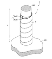
本発明の第1実施形態の補強構造4は、図1に示されるように、補強部材1を使用して既設の電柱100を補強するものである。
補強部材1は、図4に示されるように電柱100を補強した状態において、連結体2と、補強シート3(補強体)と、接着剤5を有している。
The reinforcing
The reinforcing
電柱100は、公知の電柱であり、コンクリート製に限らず、金属製、木製のいずれの電柱にも適用される。本実施形態の電柱100は、コンクリート製の電柱である。
また、電柱100は、地中や高架橋の基礎構造などの基礎構造体101に、その一部が埋められたものである。
本実施形態の電柱100は、鉄道軌道に配されている電柱であり、直径400mm、地面から高さは10m程度の円筒状となっている。
The
In addition, the
The
連結体2は、図1のように、複数の補強片6が一体化されて形成されるものである。
各補強片6は、図2に示されるように、本体部7と、接続部8から形成されている。
本体部7は、断面形状が円弧状の部位であり、内側面で電柱100の一部を覆う部位である。本体部7の内周面(内側側面)は、湾曲しており、電柱100の外周面(外側側面)に沿った形状となっている。
接続部8は、他の補強片6の本体部7と接続する部位である。接続部8は、電柱100に取り付けた状態において、他の補強片6の本体部7の一部に覆い被さる部位であり、他の補強片6の本体部7と係合可能となっている。
As shown in FIG. 1, the connecting
As shown in FIG. 2, each reinforcing
The
The
補強片6の内部構造について注目すると、補強片6は、強化繊維に樹脂を含浸させることによって一体化されたものである。すなわち、補強片6は、繊維補強された樹脂(FRP)で形成されている。
具体的には、補強片6は、図3に示されるように電柱100側(図3の下側)から順に第1繊維10、第2繊維11、第3繊維12が積層して骨格を形成しており、樹脂15によって結着させている。
本実施形態では、補強片6は、ハンドレイアップ成形にて成形されている。
When attention is paid to the internal structure of the reinforcing
Specifically, as shown in FIG. 3, the reinforcing
In this embodiment, the reinforcing
第1繊維10は、特に限定されるものではないが、補強片の運搬時や施工時に電柱100の軸方向の割れを防ぐ観点から、クロス繊維又はマットで形成されていることが好ましい。
本実施形態では、上記した外部からの損傷を防止するためにカーボンクロスを採用している。すなわち、本実施形態の第1繊維10は、縦横複数の繊維が網目状に交差して形成されている。
第1繊維10は、補強部材1で電柱100を補強したときに、電柱100の軸方向に延びる軸方向繊維16と、周方向に延びる周方向繊維17から形成されている。
すなわち、第1繊維10は、補強部材1で電柱100を補強したときに電柱100の軸方向成分と周方向成分のそれぞれに対する抗力を有している。
また、軸方向繊維16と周方向繊維17は、図3のように補強片6を引き延ばしたときに互いに直交する関係となっている。
第1繊維10は、予期せぬ振動等に対応する観点から、軸方向繊維16及び周方向繊維17の引張強さがともに200N/mm幅以上であることが好ましい。
Although the
In this embodiment, a carbon cloth is employed to prevent damage from the outside described above. That is, the
The
That is, the
Further, the
The
第2繊維11は、各繊維10,11,12の中で、補強片6の主要な骨格を形成する繊維である。
第2繊維11の材質は、特に限定されるものではないが、補強強度を高める観点からカーボン繊維を採用することが好ましい。本実施形態の第2繊維11は、電柱100の軸方向の強度を集中的に高める観点から、一方向カーボンクロスを使用している。
すなわち、第2繊維11は、補強部材1で電柱100を補強したときに、電柱100の軸方向に延びる軸方向繊維20によって形成されている。すなわち、第2繊維11は、電柱100の軸方向成分に対する抗力を有している。
また、第2繊維11は、既設の電柱100の耐震強度を補うのに十分な曲げ強度を有している。具体的には、第2繊維11は、軸方向における引張強さが2000N/mm幅以上であることが好ましく、3000N/mm幅以上となっていることがより好ましい。
The
Although the material of the
That is, the
The
第3繊維12は、特に限定されるものではないが、補強片の運搬時や施工時に電柱100の軸方向の割れを防ぐ観点から、クロス繊維又はマットで形成されていることが好ましい。本実施形態では、上記した外部からの損傷を防止するためにガラスクロスを採用している。すなわち、本実施形態の第3繊維12は、図3のように複数の繊維が網目状に交差して形成されている。
第3繊維12は、図1に示されるように電柱100を補強したときに、電柱100の軸方向に延びる軸方向繊維25と、周方向に延びる周方向繊維26から形成されている。すなわち、第3繊維12は、電柱100の軸方向成分と周方向成分のそれぞれに対する抗力を有している。
また、軸方向繊維25と周方向繊維26は、図3のように補強片6を引き延ばしたときに互いに直交する関係となっている。
The
When the
Further, the
樹脂15は、各繊維10,11,12を接着する接着樹脂であり、各繊維10,11,12を不可分一体に接着するものである。
樹脂15の材質は、熱硬化性樹脂であれば、特に限定されるものではないが、本実施形態では、ビニルエステル樹脂を採用している。
The
The material of the
以上のように、補強片6は、各繊維10,11,12を骨格とする三層構造を形成しており、疑似的には、第1繊維10を骨格とする部位はカーボン繊維補強樹脂(CFRP)で形成されており、第2繊維11を骨格とする部位はカーボン繊維補強樹脂(CFRP)で形成されており、第3繊維12を骨格とする部位はガラス繊維補強樹脂(GFRP)で形成されていることになる。
また、各繊維10,11,12は、補強片6の全長に亘って連続している。
As described above, the reinforcing
The
補強シート3は、図8から読み取れるように、長い帯状に延びた長尺状のシートであり、電柱100を補強したときに連結体2の外周面を覆う部材である。
補強シート3は、図8の拡大図のように、第4繊維30と、樹脂31から形成されており、第4繊維30に樹脂31を含浸させながら固化することによって形成されるものである。
第4繊維30は、長手方向に延びた長手方向繊維32によって形成されている。
第4繊維30は、特に限定されるものではないが、補強強度を高める観点から、カーボン繊維などが採用できる。本実施形態では、第4繊維30はカーボンクロスを使用している。
また、樹脂31の材料としては、繊維への含浸性が良く、常温で硬化するものであれば、特に限定されるものではなく、例えば、エポキシ樹脂などが使用できる。
すなわち、本実施形態の補強シート3は、疑似的には、第4繊維30を骨格として、樹脂31を含浸させたカーボン繊維補強樹脂(CFRP)で形成されている。
As can be seen from FIG. 8, the reinforcing
As shown in the enlarged view of FIG. 8, the reinforcing
The
Although the
The material of the
That is, the reinforcing
接着剤5は、図4に示されるように、電柱100と補強片6を接着する接着剤である。本実施形態の接着剤5は、粘度が高いパテ状又はペースト状の接着剤である。
接着剤5の材質は、接着機能を有したものであれば、特に限定されるものではないが、雨天等でも作業を可能とする観点から、水中硬化接着剤を採用している。
なお、本明細書では、硬化する前の接着剤5だけではなく、接着剤5が硬化したものも接着剤と呼ぶ。
As shown in FIG. 4, the adhesive 5 is an adhesive that bonds the
The material of the adhesive 5 is not particularly limited as long as it has an adhesive function, but an underwater curing adhesive is adopted from the viewpoint of enabling work even in rainy weather.
In the present specification, not only the adhesive 5 before being cured but also the one in which the adhesive 5 is cured is called an adhesive.
続いて、補強部材1によって既設の電柱100を補強し、補強構造4を形成した場合の各部位の位置関係について説明する。
なお、連結体2は、図2のように、2つの補強片6(6a,6b)によって形成されている。そこで、以下の説明においては、それぞれの補強片6を区別するために、片方の補強片6aの関する部位の符号にaを添え、もう片方の補強片6bの関する部位の符号にbを添える。
Then, the positional relationship of each site | part at the time of reinforcing the existing
In addition, the
補強部材1は、図4に示されるように、その一部が基礎構造体101中に埋め込まれている。具体的には、連結体2、補強シート3、接着剤5のそれぞれの下端部が基礎構造体101の一部を構成する充填剤36中に埋め込まれている。
連結体2は、図1のように、一方の補強片6aの接続部8と他方の補強片6bの本体部7が係合しており、一方の補強片6bの接続部8と他方の補強片6aの本体部7が係合している。電柱100の外周面と連結体2を構成する補強片6a,6bの内周面との間には、図4に示されるように接着剤5が介在している。
補強シート3は、図1に示されるように、電柱100の軸方向を中心として螺旋状に電柱100に巻き付いている。すなわち、補強シート3は、連結体2の外周面に沿って配置されている。
また、補強シート3が螺旋状に巻きつけられているので、補強シート3の内部の第4繊維30は、長手方向繊維32が軸方向及び周方向に対して傾斜している。
すなわち、長手方向繊維32は、軸方向成分と周方向成分のそれぞれに対する抗力を有している。
図4に示されるように、補強シート3は、補強シート3の幅方向の端部(上下方向の端部)が軸方向に重なっている。すなわち、軸方向下側に位置する補強シート3の上側部位に対して、軸方向上側に位置する補強シート3の下側部位が被っている。
As shown in FIG. 4, a part of the reinforcing
As shown in FIG. 1, the connecting
As shown in FIG. 1, the reinforcing
In addition, since the reinforcing
That is, the
As shown in FIG. 4, the reinforcing
続いて、第1実施形態の補強部材1を用いて、電柱100を補強する電柱の補強方法について説明する。
Then, the reinforcement method of the utility pole which reinforces the
まず、図5のように、電柱100が倒壊しない程度に電柱100の根元を支える基礎構造体101を掘り起こして根入れ部102を形成する。具体的には、電柱100の根元を20〜100cm掘り起こす。
このとき、既設の電柱100の端部は、図4から読み取れるように、根入れ部102の底部よりもさらに下方に埋まっている。
First, as shown in FIG. 5, the
At this time, the end portion of the existing
また、工場等で別途工程において成形された補強片6a,6bを根入れ部102に運び、補強片固定工程を行う。
補強片固定工程では、まず補強片6の本体部7の内面にパテ状又はペースト状の接着剤5を塗布する。
そして、図6のように、接着剤5が塗布された補強片6を電柱100に張り付けて、補強片6a,6bで電柱100を周方向に覆う。
このとき、補強片6aの接続部8と他の補強片6bの本体部7を係合し、一体化させて電柱100を周方向に覆う連結体2を形成する。すなわち、補強片6a,6bを係合させて、1つの筒状の連結体2を形成している。
連結体2を構成する補強片6a,6bは、電柱100の中間部を覆っており、電柱100の軸方向に延伸している。
補強片6a,6bは、根入れ部102の底部から電柱100の長手方向の1/5〜1/2まで延びていることが好ましい。また、補強片6a,6bの下端部は、根入れ部102内に位置していることが好ましい。
また、本実施形態の連結体2は、その上端部が施工完了後において、電柱100の周りを基礎構造体101から2〜5mまでの範囲を囲むように電柱100に取り付けられている。
Further, the reinforcing
In the reinforcing piece fixing step, first, the putty-like or paste-
Then, as shown in FIG. 6, the reinforcing
At this time, the connecting
Reinforcing
It is preferable that the reinforcing
Moreover, the
そして、図7に示されるように、バンド部材35によって補強片6a,6bが電柱100から離反しないように締め付け、接着剤5を固化させる。
このとき使用するバンド部材35は、電柱100に対する補強片6a,6bの離反を防止できれば、特に限定されるものではない。バンド部材35としては、例えば、鋼製バンドなどが採用できる。
またこのとき、補強片6a,6bは、図7のように、バンド部材35によって互いに固定され、電柱100の周りを環状に囲んだ状態となっている。
Then, as shown in FIG. 7, the reinforcing
The
Further, at this time, the reinforcing
ここで、バンド部材35について説明する。バンド部材35は、図7のように補強片6間の相対的な位置決めをする部材であって、周方向に隣接する補強片6a,6b間の離反を防止する部材である。バンド部材35は、線状の部材であって、使用時には環状にして結束する部材である。具体的には、鉄製の結束バンドである。
Here, the
そして、補強片6と電柱100との間に介在した接着剤5が乾燥して固化すると、必要に応じて、バンド部材35を取り外し、補強片固定工程を終了する。
And if the
続いて、補強シート形成工程を行う。すなわち、補強片6の外周面に第4繊維30に樹脂31を含浸させながら、電柱100の周方向に螺旋状に巻きつけて補強シート3を形成する。
このとき、補強シート3は、連結体2の外側側面と密着している。
Subsequently, a reinforcing sheet forming step is performed. That is, the reinforcing
At this time, the reinforcing
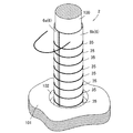
補強シート3が形成されると、補強シート形成工程を終了し、図9に示されるように根入れ部102に充填剤36を充填して、電柱100の補強が完了する。
このとき使用できる充填剤36としては、例えば、砂やモルタルなどが使用できる。
またこのとき、連結体2及び補強シート3の一部は、充填剤36を介して基礎構造体101に埋められる。
When the reinforcing
Examples of the
At this time, a part of the connecting
本実施形態の補強部材1であれば、軽量であるため、最小限の人数による手作業が可能であり、作業者の負担が少ない。また、人件コストを低減することが可能である。
Since the reinforcing
本実施形態の補強部材1であれば、あらかじめ成形された補強片6を使用するため、作業現場で成形する必要がなく、根入れ部102に挿入するだけの空間があればよい。それ故に、作業現場で補強片6を成形する場合に比べて作業空間を広く形成する必要がなく、余計な掘り起こしを行う必要は無い。
In the reinforcing
本実施形態の補強部材1であれば、複数の補強片6を電柱の周方向に一体化させて形成されているため、個別に補強片6を現場に搬入することが可能であり、補強片6が重たくなりすぎず、安全で作業性がよい。
If it is the reinforcing
本実施形態の電柱の補強方法であれば、あらかじめ成形された補強片6を使用しているため、樹脂含浸・繊維配向状態などが均一で良質な補強片6を使用することが可能であり、作業現場での補強片6自体の管理が不要である。
If it is the reinforcing method of the electric pole of this embodiment, it is possible to use the reinforcing
上記した第1実施形態では、補強シート3を連結体2の外周面に螺旋状に巻きつけて、電柱100を補強したが、本発明はこれに限定されるものではなく、補強シートの形状及び取り付け方は限定されない。
例えば、図10のように、第1実施形態の補強シート3に比べて長さが短い補強シート53を使用してもよい。
この場合の補強方法について第2実施形態として説明する。
In the first embodiment described above, the reinforcing
For example, as shown in FIG. 10, a reinforcing
A reinforcing method in this case will be described as a second embodiment.
第2実施形態の補強方法では、補強シート形成工程において、補強シート3の代わりに、補強シート53の長手方向の長さが連結体2の外周の長さ以上のものを使用する。補強シート53の長手方向の長さが外周を1.5周以上の長さのものを使用することが好ましい。
補強シート53は、第1実施形態の補強シート3と寸法以外は同様である。
そして、補強シート形成工程において、図10のように、電柱100の周りを覆った連結体2の外周を複数の補強シート53を所定の高さに至るまでそれぞれ環状に巻いていく。
このとき、軸方向において、隣接する補強シート53,53は、その一部が重なっている。
また、各補強シート53は、軸方向に平行となっている。すなわち、補強シート53の第4繊維30は、長手方向繊維32が周方向に対する抗力を有している。
In the reinforcing method of the second embodiment, in the reinforcing sheet forming step, instead of the reinforcing
The reinforcing
Then, in the reinforcing sheet forming step, as shown in FIG. 10, a plurality of reinforcing
At this time, in the axial direction, adjacent reinforcing
Each reinforcing
第2実施形態の補強方法によれば、補強シート53を小分けにして形成できるので、作業場での補強作業が行いやすい
According to the reinforcing method of the second embodiment, since the reinforcing
上記した実施形態では、補強片6の内周面にあらかじめ接着剤5を塗布して電柱100に張り付けたが、本発明はこれに限定されるものではない。例えば、連結体2を組み立ててから、接着剤を導入してもよい。
この場合の補強方法について第3実施形態として説明する。
In the above-described embodiment, the adhesive 5 is applied in advance to the inner peripheral surface of the reinforcing
A reinforcing method in this case will be described as a third embodiment.
第3実施形態の電柱の補強方法では、補強片固定工程において、補強片6に接着剤5を塗布せずに、連結体2を組み立てて、バンド部材35によって固定する(連結体形成工程)。
このとき、連結体2の内周面と電柱100の外周面の間には、図11のように隙間66が形成されている。
隙間66は、1mm以上4mm以下であることが好ましい。隙間66が1mmよりも小さくなると、接着剤65が充填しにくくなり、作業性が低下するおそれがある。隙間66が4mmよりも大きくなると、電柱100と連結体2間でがたつきが生じやすく、電柱100に対して連結体2が傾いて固定されるおそれがある。
In the reinforcing method of the utility pole of the third embodiment, in the reinforcing piece fixing step, the connecting
At this time, a
The
そして、隙間66に接着剤供給手段68と接続されたチューブ67を差し込み、チューブ67を連結体2の下端部近傍までたらす。
このとき、チューブ67は、隙間66の内部であって、根入れ部102の底部近傍まで至っている。
Then, the
At this time, the
その後、チューブ67から接着剤供給手段68によって、接着剤65を注入していき、接着剤65が所定の高さまで至ったら、接着剤65の供給を止め、チューブ67を抜いて、接着剤65を固化させる(接着剤固化工程)。
本実施形態では、接着剤65が連結体2の頂部からあふれ、連結体2の頂部まで接着剤65が充填されたことを確認したら、接着剤65の供給を止め、チューブ67を抜く。
なお、このとき使用する接着剤65は、流動性を有した液体状の接着剤である。
Thereafter, the adhesive 65 is injected from the
In this embodiment, when it is confirmed that the adhesive 65 overflows from the top of the
Note that the adhesive 65 used at this time is a liquid adhesive having fluidity.
第3実施形態の電柱の補強方法であれば、補強片6と電柱100との間に液体状の接着剤65を注入するため、塗りむらなどを防ぐことができる。
In the method for reinforcing a utility pole according to the third embodiment, since the
上記した実施形態では、補強片6の骨格を第1繊維10と第2繊維11と第3繊維12の3層によって形成していたが、本発明はこれに限定されるものではなく、第1繊維10と第3繊維12は、電柱100を補強した際に第2繊維11によって十分な横方向の強度(電柱100の周方向の強度)を有していれば省いても良い。
In the above-described embodiment, the skeleton of the reinforcing
上記した実施形態では、鉄道軌道に配される電柱を補強するものであったが、本発明はこれに限定されるものではなく、道路等に配される電柱を補強してもよい。この場合、鉄道軌道に配される電柱とは異なり、道路等に配される電柱は断面形状が等脚台形となるため、電柱の外側側面に沿った補強部材1の内側側面を形成することが好ましい。
In the above-described embodiment, the electric pole arranged on the railroad track is reinforced. However, the present invention is not limited to this, and the electric pole arranged on the road or the like may be reinforced. In this case, unlike the utility poles arranged on the railroad track, the utility poles arranged on the road or the like have an isosceles trapezoidal cross section, so that the inner side surface of the reinforcing
上記した実施形態では、接続部によって本体部の一部を覆う構成としたが、本発明はこれに限定されるものではなく、補強片間を接続できればよい。すなわち、周方向の接続部は設けなくても構わない。 In the above-described embodiment, a part of the main body is covered with the connecting portion. However, the present invention is not limited to this, and it is only necessary to connect the reinforcing pieces. That is, it is not necessary to provide a circumferential connecting portion.
上記した実施形態では、電柱の周方向に2分割となるような補強片を使用したが、本発明はこれに限定されるものではなく、電柱の周方向に複数分割できる補強片であればよい。例えば、3分割となるような補強片であってもよい。なお、部品点数が多くなりすぎない観点から2分割又は3分割となるような補強片であることが好ましい。 In the above-described embodiment, the reinforcing piece that is divided into two in the circumferential direction of the utility pole is used. However, the present invention is not limited to this, and may be any reinforcing piece that can be divided into a plurality of parts in the circumferential direction of the utility pole. . For example, the reinforcing piece may be divided into three parts. In addition, it is preferable that it is a reinforcement piece which becomes 2 division or 3 division from a viewpoint that the number of parts does not increase too much.
上記した実施形態では、補強作業を行う作業現場にて、補強シートを形成したが、本発明はこれに限定されるものではなく、あらかじめ工場等によって補強シートを形成してもよい。この場合、補強シートに接着剤を塗布して連結体の外周面に接着することが好ましい。 In the above embodiment, the reinforcing sheet is formed at the work site where the reinforcing work is performed. However, the present invention is not limited to this, and the reinforcing sheet may be formed in advance by a factory or the like. In this case, it is preferable to apply an adhesive to the reinforcing sheet and adhere to the outer peripheral surface of the connector.
上記した実施形態では、補強片6をハンドレイアップ成形によって形成したが、本発明はこれに限定されるものではなく、ハンドレイアップ成形以外の方法で成形してもよい。例えば、補強片6を引抜成形によって成形してもよい。
In the above-described embodiment, the reinforcing
以下に、実施例をもって本発明をさらに具体的に説明するが、本発明はこれらの実施例に限定されるものではない。 Hereinafter, the present invention will be described more specifically with reference to examples. However, the present invention is not limited to these examples.
次に本発明の方法による電柱補修の効果を調べる試験について説明する。 Next, a test for examining the effect of utility pole repair by the method of the present invention will be described.
試験概要を図12に示す。
本発明の補強部材1の性能を測る試験体として、以下のものを用いた。
電柱100は、電車路線用ポール 12−40−N200B(長さ:12m、末口・元口径:40cm、曲げモーメント:200kN・m)を使用した。
補強片6は、第2繊維11として東レ製クロス UT70-30G11枚を繊維が軸方向に揃うように積層し、その内層表面に第3繊維12としてガラスマット、第2繊維11の外層表面に第1繊維10としてカーボンクロス材を設けた。そして、これらを、ビニルエステル樹脂を使用して一体化した。
補強シート3は、第4繊維30として東レクロス UT70-30Gを使用し、補強片6を一体化した連結体2の周囲に周方向に2周巻きつけた。
An outline of the test is shown in FIG.
The following were used as test bodies for measuring the performance of the reinforcing
As the
The reinforcing
The reinforcing
続いて、試験体の組み立てについて説明する。
まず、電柱100の端部から1.6m離れた位置から6.6m離れた位置までエポキシ樹脂製の接着剤を塗布した補強片6を取り付け、硬化させた。すなわち、電柱100の中間部において長手方向で5mに亘る範囲を連結体2で補強した。また、補強シート3を連結体2の外側から巻きつけて補強部材1を形成した。
そして、地面に対して直立した壁と一体となった固定金具に電柱100を固定した。具体的には、固定金具の固定穴に補強部材1で補強した電柱100の端部から2mの範囲を挿入した。さらに、電柱100と固定穴の内壁の隙間を充填剤であるモルタルで埋めて、電柱100を固定金具に対して固定した。このとき、補強部材1の一部(補強部材1の端部から0.4m離れた位置までの範囲)を固定金具の固定穴の内部に位置させて、モルタルによって埋設した。このようにして試験体を組み立てた。
Next, the assembly of the test body will be described.
First, the reinforcing
And the
試験方法は、電柱100の端部から9mの位置に水平方向の荷重を加えた。
具体的には、電柱100のもう一方の端部から5mの位置に一定の荷重にて左右3回の交番載荷を行い、破壊が確認されない場合は、振幅量を増加させ同様の交番載荷を行った。
試験体が破壊、あるいは荷重の増加がみられなくなるまで、振幅量を増加して交番載荷を繰り返していった。
The test method applied a horizontal load at a position 9 m from the end of the
Specifically, alternating loading is performed three times on the left and right sides with a constant load at a position 5 m from the other end of the
The alternating loading was repeated by increasing the amplitude until the specimen was broken or no increase in load was observed.
試験結果は無補強の電柱は、荷重69.1kN(曲げモーメント484kN・m)で破壊した。
本発明の補強部材で補強した試験体は、最高荷重113.1kN(曲げモーメント792kN・m)まで荷重をかけることができた。それ以上振幅量を増やして載荷しても荷重は上がらなかった。
As a result of the test, the unreinforced utility pole was broken at a load of 69.1 kN (bending moment of 484 kN · m).
The specimen reinforced with the reinforcing member of the present invention was able to apply a load up to a maximum load of 113.1 kN (bending moment of 792 kN · m). Even if the amplitude was increased further, the load did not increase.
結果から明らかなように、無補強の電柱に比較して、補強部材1によって補強を施した電柱は、明らかに強度が向上した。
As is apparent from the results, the strength of the utility pole reinforced with the reinforcing
1 補強部材
2 連結体
3,53 補強シート(補強体)
4 補強構造
5,65 接着剤
6,6a,6b 補強片
11 第2繊維
15 樹脂
30 第4繊維
66 隙間
100 電柱
101 基礎構造体
DESCRIPTION OF
DESCRIPTION OF
Claims (9)
複数の補強片を有し、
前記複数の補強片を一体化させて、前記電柱の周方向に電柱を覆う連結体を形成するものであり、
前記連結体は、繊維補強された樹脂によって形成されており、当該繊維の配向は、電柱の軸方向成分を有していることを特徴とする補強部材。 In a reinforcing member that reinforces an existing utility pole,
Having a plurality of reinforcing pieces,
The plurality of reinforcing pieces are integrated to form a connecting body that covers the power pole in the circumferential direction of the power pole,
The connecting member is formed of a resin reinforced with fibers, and the orientation of the fibers includes an axial component of a utility pole.
前記補強体は、前記電柱の軸方向に対して直交方向の成分をもって配向した繊維を有していることを特徴とする請求項1〜3のいずれかに記載の補強部材。 A reinforcing body covers the outer periphery of the connecting body,
The reinforcing member according to any one of claims 1 to 3, wherein the reinforcing body has fibers oriented with a component orthogonal to the axial direction of the utility pole.
前記電柱及び連結体のそれぞれの一部は、基礎構造体中に埋め込まれていることを特徴とする補強構造。 A reinforcing structure for reinforcing a power pole using the reinforcing member according to claim 1,
A part of each of the said utility pole and a connection body is embedded in the foundation structure, The reinforcement structure characterized by the above-mentioned.
前記補強片と前記電柱との間に接着剤を介在させて固化することによって、前記補強部材と前記電柱を一体化することを特徴とする電柱の補強方法。 In the reinforcement method of the utility pole which reinforces the existing utility pole using the reinforcement member in any one of Claims 1-4,
A method for reinforcing an electric pole, comprising: integrating the reinforcing member and the electric pole by solidifying with an adhesive interposed between the reinforcing piece and the electric pole.
当該隙間に流動性を有した接着剤を充填することを特徴とする請求項7に記載の電柱の補強方法。 A gap of 1 mm or more and 4 mm or less is formed between the reinforcing member and the utility pole,
The method for reinforcing a utility pole according to claim 7, wherein the gap is filled with a fluid adhesive.
Priority Applications (1)
| Application Number | Priority Date | Filing Date | Title |
|---|---|---|---|
| JP2014119526A JP2015232237A (en) | 2014-06-10 | 2014-06-10 | Reinforcement member, reinforcement structure, and electric pole reinforcing method |
Applications Claiming Priority (1)
| Application Number | Priority Date | Filing Date | Title |
|---|---|---|---|
| JP2014119526A JP2015232237A (en) | 2014-06-10 | 2014-06-10 | Reinforcement member, reinforcement structure, and electric pole reinforcing method |
Publications (1)
| Publication Number | Publication Date |
|---|---|
| JP2015232237A true JP2015232237A (en) | 2015-12-24 |
Family
ID=54933846
Family Applications (1)
| Application Number | Title | Priority Date | Filing Date |
|---|---|---|---|
| JP2014119526A Pending JP2015232237A (en) | 2014-06-10 | 2014-06-10 | Reinforcement member, reinforcement structure, and electric pole reinforcing method |
Country Status (1)
| Country | Link |
|---|---|
| JP (1) | JP2015232237A (en) |
Cited By (6)
| Publication number | Priority date | Publication date | Assignee | Title |
|---|---|---|---|---|
| KR101726750B1 (en) * | 2016-05-26 | 2017-04-13 | 한국기술개발 주식회사 | Repairing and reinfocing method for concrete structure |
| JP2018012996A (en) * | 2016-07-21 | 2018-01-25 | 中国電力株式会社 | Repair member and repair method for existing hollow tube |
| JP2020170685A (en) * | 2019-04-05 | 2020-10-15 | 中国電力株式会社 | Insulation tape for utility pole and insulation device for utility pole |
| JP2021132508A (en) * | 2020-02-21 | 2021-09-09 | 北海道電力株式会社 | Repair member for columnar workpiece, columnar workpiece, and repair method thereof |
| CN113884368A (en) * | 2021-09-26 | 2022-01-04 | 北京天海氢能装备有限公司 | Preparation method and preparation frame of carbon fiber tensile sample and sample |
| JP2022011606A (en) * | 2020-06-30 | 2022-01-17 | 東洋道路施設株式会社 | Reinforcement structure, and manufacturing method of reinforcement structure |
Citations (14)
| Publication number | Priority date | Publication date | Assignee | Title |
|---|---|---|---|---|
| JPS6314945A (en) * | 1986-07-03 | 1988-01-22 | 清水建設株式会社 | Method for reinforcing concrete columnar body due to high strength fiber prereg |
| JPH06323000A (en) * | 1993-05-14 | 1994-11-22 | Tonen Corp | Manufacture of concrete column |
| JPH06322998A (en) * | 1993-05-14 | 1994-11-22 | Tonen Corp | Concrete column |
| JPH0913693A (en) * | 1995-06-29 | 1997-01-14 | Alpha Kogyo Kk | Repairing method of column body |
| JPH09250247A (en) * | 1996-03-18 | 1997-09-22 | Mitsubishi Heavy Ind Ltd | Composite material reinforced concrete structural body |
| JPH108423A (en) * | 1996-06-19 | 1998-01-13 | Mitsubishi Jisho Kk | Reinforcement method of concrete structure |
| JPH10159027A (en) * | 1996-11-27 | 1998-06-16 | Saeki Kensetsu Kogyo Kk | Earthquake-resistant reinforcing method for existing structure and reinforcing construction |
| JP2002155509A (en) * | 2000-09-08 | 2002-05-31 | Nittetsu Corrosion Prevention Co Ltd | Reinforcing structure and reinforcement method for concrete structure |
| JP2002254537A (en) * | 2001-02-27 | 2002-09-11 | Nippon Steel Composite Co Ltd | Reinforcing fiber sheet and method for manufacturing the same |
| JP3488191B2 (en) * | 2000-09-14 | 2004-01-19 | 三井住友建設株式会社 | Reinforcing method for the root of concrete electric pole |
| JP2007009482A (en) * | 2005-06-29 | 2007-01-18 | Nittetsu Corrosion Prevention Co Ltd | Reinforcing structure and reinforcing method of concrete structure |
| US20090266026A1 (en) * | 2008-04-28 | 2009-10-29 | Hannay Richard C | Method For Repairing A Utility Pole In Place |
| JP2010037776A (en) * | 2008-08-04 | 2010-02-18 | Tokyu Construction Co Ltd | Device for winding reinforcing sheet, and method of reinforcing concrete structure |
| JP2012012870A (en) * | 2010-07-02 | 2012-01-19 | Sumitomo Mitsui Construction Co Ltd | Method for reinforcing structure |
-
2014
- 2014-06-10 JP JP2014119526A patent/JP2015232237A/en active Pending
Patent Citations (14)
| Publication number | Priority date | Publication date | Assignee | Title |
|---|---|---|---|---|
| JPS6314945A (en) * | 1986-07-03 | 1988-01-22 | 清水建設株式会社 | Method for reinforcing concrete columnar body due to high strength fiber prereg |
| JPH06323000A (en) * | 1993-05-14 | 1994-11-22 | Tonen Corp | Manufacture of concrete column |
| JPH06322998A (en) * | 1993-05-14 | 1994-11-22 | Tonen Corp | Concrete column |
| JPH0913693A (en) * | 1995-06-29 | 1997-01-14 | Alpha Kogyo Kk | Repairing method of column body |
| JPH09250247A (en) * | 1996-03-18 | 1997-09-22 | Mitsubishi Heavy Ind Ltd | Composite material reinforced concrete structural body |
| JPH108423A (en) * | 1996-06-19 | 1998-01-13 | Mitsubishi Jisho Kk | Reinforcement method of concrete structure |
| JPH10159027A (en) * | 1996-11-27 | 1998-06-16 | Saeki Kensetsu Kogyo Kk | Earthquake-resistant reinforcing method for existing structure and reinforcing construction |
| JP2002155509A (en) * | 2000-09-08 | 2002-05-31 | Nittetsu Corrosion Prevention Co Ltd | Reinforcing structure and reinforcement method for concrete structure |
| JP3488191B2 (en) * | 2000-09-14 | 2004-01-19 | 三井住友建設株式会社 | Reinforcing method for the root of concrete electric pole |
| JP2002254537A (en) * | 2001-02-27 | 2002-09-11 | Nippon Steel Composite Co Ltd | Reinforcing fiber sheet and method for manufacturing the same |
| JP2007009482A (en) * | 2005-06-29 | 2007-01-18 | Nittetsu Corrosion Prevention Co Ltd | Reinforcing structure and reinforcing method of concrete structure |
| US20090266026A1 (en) * | 2008-04-28 | 2009-10-29 | Hannay Richard C | Method For Repairing A Utility Pole In Place |
| JP2010037776A (en) * | 2008-08-04 | 2010-02-18 | Tokyu Construction Co Ltd | Device for winding reinforcing sheet, and method of reinforcing concrete structure |
| JP2012012870A (en) * | 2010-07-02 | 2012-01-19 | Sumitomo Mitsui Construction Co Ltd | Method for reinforcing structure |
Cited By (8)
| Publication number | Priority date | Publication date | Assignee | Title |
|---|---|---|---|---|
| KR101726750B1 (en) * | 2016-05-26 | 2017-04-13 | 한국기술개발 주식회사 | Repairing and reinfocing method for concrete structure |
| JP2018012996A (en) * | 2016-07-21 | 2018-01-25 | 中国電力株式会社 | Repair member and repair method for existing hollow tube |
| JP2020170685A (en) * | 2019-04-05 | 2020-10-15 | 中国電力株式会社 | Insulation tape for utility pole and insulation device for utility pole |
| JP7387997B2 (en) | 2019-04-05 | 2023-11-29 | 中国電力株式会社 | Utility pole insulation treatment method and insulator for utility poles |
| JP2021132508A (en) * | 2020-02-21 | 2021-09-09 | 北海道電力株式会社 | Repair member for columnar workpiece, columnar workpiece, and repair method thereof |
| JP2022011606A (en) * | 2020-06-30 | 2022-01-17 | 東洋道路施設株式会社 | Reinforcement structure, and manufacturing method of reinforcement structure |
| JP7300732B2 (en) | 2020-06-30 | 2023-06-30 | 東洋道路施設株式会社 | Reinforcing structure and method for manufacturing reinforcing structure |
| CN113884368A (en) * | 2021-09-26 | 2022-01-04 | 北京天海氢能装备有限公司 | Preparation method and preparation frame of carbon fiber tensile sample and sample |
Similar Documents
| Publication | Publication Date | Title |
|---|---|---|
| JP2015232237A (en) | Reinforcement member, reinforcement structure, and electric pole reinforcing method | |
| JPS61162674A (en) | Repairing of utility pole | |
| CN1031876A (en) | Improved pole repair system | |
| JP5065053B2 (en) | Method for strengthening cylindrical metal structure and structure obtained thereby | |
| CA2892302C (en) | Reinforcing structure for concrete column | |
| CN107575246B (en) | A kind of construction method of pre-manufactured steel-FRP complex wave card tunnel bottom supporting construction | |
| JP2012127134A (en) | Reinforcement material and reinforcement method of concrete column body | |
| CN102108680B (en) | Bridge pier consolidating method and device | |
| JP4264095B2 (en) | Manhole reinforcement structure | |
| JP6948503B2 (en) | How to reinforce concrete structures, concrete structures and flexible continuous fiber reinforcements | |
| CN104284702B (en) | Stacked rolling vehicle track | |
| JP6811678B2 (en) | Method of joining concrete structures and concrete members to which continuous fiber reinforced concrete is applied | |
| JP2001098767A (en) | Reinforcing construction method of reinforced concrete structure | |
| JP6814575B2 (en) | Protective structure and protection method for underground pipes | |
| CN104453939B (en) | Rail tunnel lightweight compound material supporting structural member and installation method thereof | |
| JP5428899B2 (en) | Method for reinforcing tower-like structures | |
| JP6563801B2 (en) | Column reinforcing method and column reinforcing structure | |
| JP5826570B2 (en) | Protective pipe repair method for existing bridge and formwork material used in the method | |
| KR20140039131A (en) | Track sleeper and switching gear made of composite material | |
| JP4171018B2 (en) | Manhole reinforcement structure | |
| CN211396281U (en) | Reinforced wood structure column | |
| CN103912741B (en) | Pipeline and attaching method thereof | |
| KR102285004B1 (en) | Concrete Column Structures Reinforcing Method Using Reinforced Steel Plate | |
| JP5098747B2 (en) | Reusable sound barrier, its installation method and its removal method | |
| JP3151722B2 (en) | Method and material for reinforcing concrete column |
Legal Events
| Date | Code | Title | Description |
|---|---|---|---|
| A621 | Written request for application examination |
Free format text: JAPANESE INTERMEDIATE CODE: A621 Effective date: 20170118 |
|
| A977 | Report on retrieval |
Free format text: JAPANESE INTERMEDIATE CODE: A971007 Effective date: 20171026 |
|
| A131 | Notification of reasons for refusal |
Free format text: JAPANESE INTERMEDIATE CODE: A131 Effective date: 20171116 |
|
| A521 | Request for written amendment filed |
Free format text: JAPANESE INTERMEDIATE CODE: A523 Effective date: 20171212 |
|
| A131 | Notification of reasons for refusal |
Free format text: JAPANESE INTERMEDIATE CODE: A131 Effective date: 20180507 |
|
| A521 | Request for written amendment filed |
Free format text: JAPANESE INTERMEDIATE CODE: A523 Effective date: 20180605 |
|
| A02 | Decision of refusal |
Free format text: JAPANESE INTERMEDIATE CODE: A02 Effective date: 20181025 |
|
| A521 | Request for written amendment filed |
Free format text: JAPANESE INTERMEDIATE CODE: A523 Effective date: 20190116 |
|
| A911 | Transfer to examiner for re-examination before appeal (zenchi) |
Free format text: JAPANESE INTERMEDIATE CODE: A911 Effective date: 20190123 |
|
| A912 | Re-examination (zenchi) completed and case transferred to appeal board |
Free format text: JAPANESE INTERMEDIATE CODE: A912 Effective date: 20190315 |