JP2015227182A - Gas tank and protection method of the same - Google Patents
Gas tank and protection method of the same Download PDFInfo
- Publication number
- JP2015227182A JP2015227182A JP2014113137A JP2014113137A JP2015227182A JP 2015227182 A JP2015227182 A JP 2015227182A JP 2014113137 A JP2014113137 A JP 2014113137A JP 2014113137 A JP2014113137 A JP 2014113137A JP 2015227182 A JP2015227182 A JP 2015227182A
- Authority
- JP
- Japan
- Prior art keywords
- tank
- tank body
- opening
- gas
- side wall
- Prior art date
- Legal status (The legal status is an assumption and is not a legal conclusion. Google has not performed a legal analysis and makes no representation as to the accuracy of the status listed.)
- Granted
Links
- 238000000034 method Methods 0.000 title claims abstract description 10
- 239000013535 sea water Substances 0.000 claims description 46
- XLYOFNOQVPJJNP-UHFFFAOYSA-N water Substances O XLYOFNOQVPJJNP-UHFFFAOYSA-N 0.000 claims description 27
- 230000007246 mechanism Effects 0.000 claims description 12
- 230000002093 peripheral effect Effects 0.000 claims description 10
- 101000612856 Dictyostelium discoideum Probable serine/threonine-protein kinase tsuA Proteins 0.000 description 34
- 239000007789 gas Substances 0.000 description 33
- 230000029058 respiratory gaseous exchange Effects 0.000 description 30
- IJGRMHOSHXDMSA-UHFFFAOYSA-N Atomic nitrogen Chemical compound N#N IJGRMHOSHXDMSA-UHFFFAOYSA-N 0.000 description 12
- 229910001873 dinitrogen Inorganic materials 0.000 description 10
- XEEYBQQBJWHFJM-UHFFFAOYSA-N Iron Chemical compound [Fe] XEEYBQQBJWHFJM-UHFFFAOYSA-N 0.000 description 4
- 229910000831 Steel Inorganic materials 0.000 description 4
- 239000010959 steel Substances 0.000 description 4
- 230000000903 blocking effect Effects 0.000 description 3
- 238000004891 communication Methods 0.000 description 3
- 238000000605 extraction Methods 0.000 description 3
- 239000002341 toxic gas Substances 0.000 description 3
- QGZKDVFQNNGYKY-UHFFFAOYSA-N Ammonia Chemical compound N QGZKDVFQNNGYKY-UHFFFAOYSA-N 0.000 description 2
- 239000011261 inert gas Substances 0.000 description 2
- 238000009434 installation Methods 0.000 description 2
- 239000011810 insulating material Substances 0.000 description 2
- 229910052742 iron Inorganic materials 0.000 description 2
- 230000003014 reinforcing effect Effects 0.000 description 2
- 230000004044 response Effects 0.000 description 2
- 238000007789 sealing Methods 0.000 description 2
- 239000003570 air Substances 0.000 description 1
- 229910021529 ammonia Inorganic materials 0.000 description 1
- QVGXLLKOCUKJST-UHFFFAOYSA-N atomic oxygen Chemical compound [O] QVGXLLKOCUKJST-UHFFFAOYSA-N 0.000 description 1
- 230000008859 change Effects 0.000 description 1
- 238000010586 diagram Methods 0.000 description 1
- 230000005484 gravity Effects 0.000 description 1
- 238000009413 insulation Methods 0.000 description 1
- 239000007788 liquid Substances 0.000 description 1
- 239000000463 material Substances 0.000 description 1
- 238000012986 modification Methods 0.000 description 1
- 230000004048 modification Effects 0.000 description 1
- 229910052757 nitrogen Inorganic materials 0.000 description 1
- 231100000252 nontoxic Toxicity 0.000 description 1
- 230000003000 nontoxic effect Effects 0.000 description 1
- NJPPVKZQTLUDBO-UHFFFAOYSA-N novaluron Chemical compound C1=C(Cl)C(OC(F)(F)C(OC(F)(F)F)F)=CC=C1NC(=O)NC(=O)C1=C(F)C=CC=C1F NJPPVKZQTLUDBO-UHFFFAOYSA-N 0.000 description 1
- 239000001301 oxygen Substances 0.000 description 1
- 229910052760 oxygen Inorganic materials 0.000 description 1
- 229910001562 pearlite Inorganic materials 0.000 description 1
- 230000009466 transformation Effects 0.000 description 1
- 238000003466 welding Methods 0.000 description 1
Images


Abstract
Description
本発明は、ガスタンクおよびガスタンクの保護方法に関する。 The present invention relates to a gas tank and a method for protecting the gas tank.
特許文献1に記載されるように、内槽と外槽とを備える低温タンクが知られている。この低温タンクは、地中を掘削して設けられたピット内に設けられている。内槽には、LNG等の低温液体が貯留される。内槽と外槽との間には保冷材が充填され、さらに窒素ガスが封入されている。外槽には通気孔が設けられており、この通気孔にベローズが取り付けられている。窒素ガスの体積変動に応じて、ベローズが伸縮する。このような構成により、低温タンクの各部において生じた窒素ガスの体積変動を吸収している。
As described in
一方、津波または地震等からタンクを保護する各種の技術が知られている。たとえば、特許文献2に記載された津波対策工では、タンクの外側に、自立式の津波防護柵が設置されている。特許文献3に記載された補強構造では、タンクの側板の下部に支持枠体が設けられ、その支持枠体内にコンクリートが打設されている。特許文献4に記載されたタンクは、タンク本体と、タンク本体を納める格納体とを備えている。格納体の幅は、格納体の水平方向の一端から中央部に向けて漸増している。格納体は、津波の浸入が予想される側にその一端が向けられるよう、設定されている。
On the other hand, various techniques for protecting a tank from a tsunami or an earthquake are known. For example, in the tsunami countermeasure work described in Patent Document 2, a self-supporting tsunami protection fence is installed outside the tank. In the reinforcing structure described in Patent Document 3, a support frame is provided at the lower part of the side plate of the tank, and concrete is placed in the support frame. The tank described in
従来、ブリージングタンクまたはガスの貯蔵タンクにおける津波または高潮対策は、設置場所が浸水域にならないような検討がされてきたが、これらのガスタンクの設置場所に津波または高潮が到達し得る場合には、ガスタンクの周りに海水が流れ込むことが考えられる。その場合、タンク本体に水圧が加わることによりタンク本体が圧壊したり、タンク本体に浮力が加わることによりタンク本体が浮き上がったりするおそれがある。このように、津波または高潮が到達した場合に、タンク本体を保護することは難しい。 Conventionally, tsunami or storm surge countermeasures in breathing tanks or gas storage tanks have been studied so that the installation location does not become a flooded area, but if a tsunami or storm surge can reach these gas tank installation locations It is conceivable that seawater flows around the gas tank. In that case, there is a possibility that the tank body may be crushed by applying water pressure to the tank body, or the tank body may be lifted by adding buoyancy to the tank body. Thus, it is difficult to protect the tank body when a tsunami or storm surge arrives.
本発明は、津波または高潮が到達した場合であっても、タンク本体の圧壊および浮き上がりを防止することができるガスタンクおよびガスタンクの保護方法を提供することを目的とする。 An object of the present invention is to provide a gas tank and a method for protecting the gas tank that can prevent the tank body from being crushed and lifted even when a tsunami or storm surge arrives.
本発明は、タンク本体の内部にガスが貯留されるガスタンクであって、タンク本体の側壁に設けられて、タンク本体の内外を連通する開口部と、開口部を塞ぐようにして側壁に設けられた閉塞部と、を備え、閉塞部が移動または変形することにより、開口部の少なくとも一部が露出する。 The present invention is a gas tank in which gas is stored inside a tank body, provided on a side wall of the tank body, and provided on the side wall so as to close the opening, and an opening communicating with the inside and outside of the tank body. And at least a part of the opening is exposed by the movement or deformation of the blocking part.
このガスタンクによれば、タンク本体の側面に設けられた開口部は、閉塞部によって塞がれる。閉塞部が移動または変形することにより、開口部の少なくとも一部が露出し、タンク本体の内外が連通する。よって、津波または高潮がタンク本体に到達する場合に、閉塞部を移動または変形させることにより、海水をタンク本体の内部に導入することができる。タンク本体の内部に海水が導入されると、タンク本体の周りに海水が存在する状態でも、タンク本体に加わる水圧および浮力が低減される。よって、津波または高潮が到達した場合であっても、タンク本体の圧壊および浮き上がりを防止することができる。 According to this gas tank, the opening provided in the side surface of the tank body is closed by the closing portion. When the closing portion moves or deforms, at least a part of the opening is exposed, and the inside and outside of the tank main body communicate with each other. Therefore, when a tsunami or storm surge reaches the tank body, the seawater can be introduced into the tank body by moving or deforming the blocking portion. When seawater is introduced into the tank body, water pressure and buoyancy applied to the tank body are reduced even when seawater is present around the tank body. Therefore, even when a tsunami or storm surge arrives, the tank body can be prevented from being crushed and lifted.
いくつかの態様において、タンク本体は、コンクリート製の基礎上に設置されており、タンク本体は、側壁と、側壁の下端に接合された底板とを含み、基礎には、底板の周縁部に対面するように露出するアンカー部材が埋設されており、底板の周縁部は、全周にわたってアンカー部材の露出部分に溶接される。この構成によれば、アンカー部材が基礎に埋設されており、タンク本体の底板の周縁部が、全周にわたってアンカー部材の露出部分に溶接される。このような構造により、タンク本体と基礎との間隙に海水が浸入することが防止される。よって、タンク本体が基礎から浮き上がることを防止できる。 In some embodiments, the tank body is installed on a concrete foundation, and the tank body includes a side wall and a bottom plate joined to a lower end of the side wall, and the foundation faces the peripheral edge of the bottom plate. The exposed anchor member is embedded, and the peripheral edge of the bottom plate is welded to the exposed portion of the anchor member over the entire circumference. According to this configuration, the anchor member is embedded in the foundation, and the peripheral portion of the bottom plate of the tank body is welded to the exposed portion of the anchor member over the entire periphery. Such a structure prevents seawater from entering the gap between the tank body and the foundation. Therefore, it is possible to prevent the tank body from floating from the foundation.
いくつかの態様において、ガスタンクは、閉塞部を閉位置に保持すると共に、閉塞部に水圧が加わった場合に閉塞部の移動を許容する開閉機構を備える。この場合、閉塞部に水圧が加わった場合に、閉塞部が移動して、タンク本体の内外が連通する。よって、津波または高潮の到達に起因する水圧を利用して、タンク本体の内部に海水を導入することができる。 In some embodiments, the gas tank includes an opening / closing mechanism that holds the closing portion in a closed position and allows movement of the closing portion when water pressure is applied to the closing portion. In this case, when water pressure is applied to the closed portion, the closed portion moves and the inside and outside of the tank main body communicate with each other. Therefore, seawater can be introduced into the tank body using the water pressure resulting from the arrival of a tsunami or storm surge.
いくつかの態様において、ガスタンクは、閉塞部を閉位置と開位置との間で移動させる駆動部と、駆動部を制御する制御部と、を備える。この場合、制御部が駆動部を制御し、閉塞部を移動することができる。閉塞部の開閉を遠隔操作することができるため、津波または高潮に対する対応性が高められる。 In some embodiments, the gas tank includes a drive unit that moves the closing unit between a closed position and an open position, and a control unit that controls the drive unit. In this case, the control unit can control the drive unit and move the blocking unit. Since it is possible to remotely control the opening and closing of the closed part, the response to tsunami or storm surge is enhanced.
いくつかの態様において、閉塞部は、水圧によって破断する板状部材を含む。この場合、閉塞部の板状部材に水圧が加わると、板状部材が破断して、タンク本体の内外が連通する。よって、津波または高潮の到達に起因する水圧を利用して、タンク本体の内部に海水を導入することができる。 In some embodiments, the closure includes a plate-like member that is broken by hydraulic pressure. In this case, when water pressure is applied to the plate-like member of the closing portion, the plate-like member is broken and the inside and outside of the tank body communicate. Therefore, seawater can be introduced into the tank body using the water pressure resulting from the arrival of a tsunami or storm surge.
いくつかの態様において、開口部および閉塞部は、タンク本体の周方向の複数箇所に設けられている。この場合、複数の開口部によって、海水を導入および流通させやすい。よって、タンク本体の内部に海水を迅速かつ容易に導入することができる。また、それぞれの開口部が設けられる方向を調整することにより、津波または高潮が到達した際に、ある開口部を海水の導入口として機能させ、他の開口部を海水の流出口として機能させることもできる。この場合、津波または高潮によってタンク本体に与えられる衝撃を緩和することができる。 In some embodiments, the opening and the closing portion are provided at a plurality of locations in the circumferential direction of the tank body. In this case, it is easy to introduce and distribute seawater through the plurality of openings. Therefore, seawater can be quickly and easily introduced into the tank body. In addition, by adjusting the direction in which each opening is provided, when a tsunami or storm surge arrives, one opening functions as seawater inlet and the other opening functions as seawater outlet. You can also. In this case, the impact given to the tank body by a tsunami or storm surge can be mitigated.
本発明は、タンク本体の内部にガスが貯留されるガスタンクの保護方法であって、タンク本体の側壁には、タンク本体の内外を連通する開口部と、開口部を塞ぐ閉塞部とが設けられており、タンク本体に津波または高潮が到達する前または到達した際に、閉塞部を移動または変形させることにより開口部の少なくとも一部を露出させて、開口部を通じて海水をタンク本体の内部に導入する。 The present invention relates to a method for protecting a gas tank in which gas is stored inside the tank body, and the side wall of the tank body is provided with an opening that communicates the inside and outside of the tank body and a closing portion that closes the opening. Before or when the tsunami or storm surge reaches the tank body, move or deform the closed part to expose at least part of the opening, and introduce seawater into the tank body through the opening. To do.
このガスタンクの保護方法によれば、タンク本体に津波または高潮が到達する前または到達した際に、閉塞部を移動または変形させることによって開口部の少なくとも一部が露出し、タンク本体の内外が連通する。そして、開口部を通じて海水をタンク本体の内部に導入するため、タンク本体の周りに海水が存在する状態でも、タンク本体に加わる水圧および浮力が低減される。よって、津波または高潮が到達する場合においても、タンク本体の圧壊および浮き上がりを防止することができる。 According to this method for protecting a gas tank, at least a part of the opening is exposed by moving or deforming the closed portion before or when the tsunami or storm surge reaches the tank body, and the inside and outside of the tank body communicate with each other. To do. And since seawater is introduce | transduced into the inside of a tank main body through an opening part, even when the seawater exists around a tank main body, the water pressure and buoyancy which are added to a tank main body are reduced. Therefore, even when a tsunami or storm surge arrives, the tank body can be prevented from being crushed and lifted.
本発明によれば、津波または高潮が到達する場合においても、タンク本体の圧壊および浮き上がりを防止することができる。 According to the present invention, even when a tsunami or storm surge arrives, the tank body can be prevented from being crushed and lifted.
以下、本発明の実施形態について、図面を参照しながら説明する。なお、図面の説明において同一要素には同一符号を付し、重複する説明は省略する。以下に説明する実施形態では、本発明がガス貯蔵システムのブリージングタンクに適用される場合について説明する。 Hereinafter, embodiments of the present invention will be described with reference to the drawings. In the description of the drawings, the same elements are denoted by the same reference numerals, and redundant descriptions are omitted. Embodiment described below demonstrates the case where this invention is applied to the breathing tank of a gas storage system.
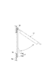
図1を参照して、ブリージングタンクを備えるガス貯蔵システムSについて説明する。ガス貯蔵システムSは、たとえばLNG等の低温液化ガスを貯蔵するためのシステムである。ガス貯蔵システムSは、たとえば海に近い沿岸に建設されている。ガス貯蔵システムSは、本実施形態のブリージングタンク(容積可変式ガス供給排出附属設備)1と、LNG等を貯蔵する低温タンク2とを備える。低温タンク2とブリージングタンク1とは、連通管3によって接続されている。
With reference to FIG. 1, the gas storage system S provided with a breathing tank is demonstrated. The gas storage system S is a system for storing a low-temperature liquefied gas such as LNG. The gas storage system S is constructed, for example, on the coast near the sea. The gas storage system S includes a breathing tank (equipment with variable volume gas supply / discharge) 1 of this embodiment and a low-temperature tank 2 for storing LNG and the like. The low temperature tank 2 and the
低温タンク2は、2重殻タンクになっており、LNG等を収容する内槽4と、内槽4を包囲する外槽5とを備える。内槽4と外槽5との間に形成された空間6には、低温タンク2の内外を断熱するための保冷材(パーライト等)が充填される。すなわち、空間6は保冷層として機能する。この空間6には、窒素ガス等の不活性ガスが封入されており、不活性雰囲気が保たれている。窒素ガスの封入圧力は、外気温や気圧の変化によって変動を生じないよう、ブリージングタンク1によって、ほぼ一定に保持される。
The low-temperature tank 2 is a double shell tank, and includes an
ブリージングタンク1は、低温タンク2の補機として、低温タンク2に付設されている。ブリージングタンク1は、上記した空間6内の窒素ガスの体積変化を吸収するために設けられたクッションタンクである。ブリージングタンク1は、たとえばコンクリート製の基礎7上に設置されている。たとえば、基礎7の下部は地中に形成されており、基礎7の上部は、地上に突出している。ブリージングタンク1は、基礎7上に設置されたタンク本体8を備える。タンク本体8は、たとえば鉄等の鋼板製であり、ブリージングタンク1のケーシングに相当する。タンク本体8の下部は円筒状をなしており、タンク本体8の上部はドーム状をなしている。
The
図2に示されるように、ブリージングタンク1は、タンク本体8の内部空間を上下に隔絶するゴム製のダイヤフラム9を備える。ダイヤフラム9は、その周縁部がタンク本体8の内壁面に固定されることにより、下部空間10と上部空間11とを画成している。下部空間10は、連通管3によって、低温タンク2の空間6に接続されている。下部空間10には、空間6に封入されている不活性ガスと同じガス、たとえば窒素ガスが封入されている。タンク本体8の頂部は大気に開放されており、上部空間11は空気によって満たされている。ダイヤフラム9の中央部には、ウェイト12が装着されている。このウェイト12の重みによって、下部空間10の窒素ガスが加圧されている。外気温や気圧の変動により窒素ガスの体積が変化するのに応じて、ダイヤフラム9の中央部が昇降する。ダイヤフラム9の昇降により、低温タンク2の空間6における窒素ガスの封入圧力が一定に保持される。なお、タンク本体8の頂部には、ベント13が取り付けられている。
As shown in FIG. 2, the
タンク本体8は、円筒状の側壁8aの下端に接合された、円板状の底板14を含む。底板14の下面は、基礎7の表面に接触している。なお、底板14は、たとえば複数の鋼板が接合されることによって、形成され得る。
The
図3(a)および図3(b)に示されるように、基礎7には、円環状のリングアンカー15が埋設されている。リングアンカー(アンカー部材)15は、たとえば、断面(延在方向に垂直な断面)がL字状の鋼材である。リングアンカー15は、基礎7内の鉄筋に溶接等によって連結されていてもよい。リングアンカー15の直径は、底板14の直径よりも大きい。リングアンカー15は、底板14の周縁部に対面するように、基礎7の表面に露出している。すなわち、リングアンカー15の露出面(露出部分)15aが、基礎7の表面と面一になっている。底板14の周縁部はリングアンカー15上に載置されており、全周にわたって、リングアンカー15の露出面15aに溶接されている。すなわち、底板14の周縁部とリングアンカー15の露出面15aとの間に、全周にわたって溶接部15bが形成されている。このような接合構造(シール構造)により、タンク本体8が基礎7に対して強固に固定されており、しかも、タンク本体8(具体的には底板14)と基礎7との間に海水が浸入することが防止されている。これにより、機械部分への海水の回り込みを防止している。
As shown in FIG. 3A and FIG. 3B, an
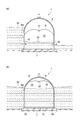
図2および図4に示されるように、ブリージングタンク1は、タンク本体8の側壁8aに設けられた複数の開口部16と、開口部16を塞ぐようにして側壁8aに設けられた蓋部(閉塞部)17とを備える。開口部16および蓋部17は、たとえば円形状である。なお、開口部16および蓋部17は、矩形状であってもよい。開口部16および蓋部17は、タンク本体8の周方向の複数箇所に設けられている。より詳細には、開口部16および蓋部17は、側壁8aの下部に設けられている。開口部16および蓋部17は、たとえば、タンク本体8の全高の半分の高さより低い位置に設けられる。
As shown in FIG. 2 and FIG. 4, the
開口部16および蓋部17は、ブリージングタンク1に津波または高潮が到達した際に、タンク本体8の内部(たとえば下部空間10)に海水を導入するための構造である。ブリージングタンク1では、津波または高潮が到達した際、蓋部17が開くことによって開口部16が露出し、開口部16を通じて海水が内部に取り込まれ得る。このような構成により、タンク本体8の圧壊、浮き上がり、損傷を防止することができる。なお、タンク本体8には、ノズルまたはマンホール等が適宜設けられるが、これらの図示は省略されている。
The
開口部16および蓋部17の構成についてより詳細に説明する。開口部16は、タンク本体8の周方向において、等間隔に3つ形成されている。開口部16は、4つ以上形成されてもよいし、2つ形成されてもよい。開口部16は、タンク本体8の周方向において等間隔に形成される場合に限られず、たとえば海に面する側により多く設けられてもよい。それぞれの開口部16および蓋部17が同一の形状および大きさを有してもよいし、異なる形状および大きさを有してもよい。
The structure of the
図4を参照して蓋部17の一例について説明すると、蓋部17は、鉄等からなる。蓋部17は、円形の開口部16に嵌まり込む円板状の嵌合部17aと、嵌合部17aから径方向に張り出すフランジ部17bとを含み得る。嵌合部17aおよびフランジ部17bの形状は、側壁8aの湾曲形状に沿って湾曲していてもよい。蓋部17と側壁8aとの間には、ガスケット等が設けられてもよい。
An example of the
蓋部17は、側壁8aに対して開閉可能に取り付けられている。蓋部17と側壁8aとの間には開閉機構18が設けられている。この開閉機構18は、たとえば、ヒンジ構造を含み得る。開閉機構18は、蓋部17に水圧が作用しない通常時には、蓋部17を閉位置(図4において実線で示される位置)に保持する。開閉機構18は、蓋部17に水圧が加わった場合に、蓋部17の移動を許容する。蓋部17は、所定の可動範囲を有しており、水圧によって、開位置(図4において仮想線で示される位置)まで移動する。蓋部17に水圧が作用しなくなった際には、蓋部17は、たとえば自重によって、閉位置に戻る。開閉機構18は、蓋部17を閉位置に付勢するばね機構を含んでもよい。
The
蓋部17は、たとえば、タンク本体8の内面側に設けられる。なお、すべての蓋部17が、タンク本体8の内面側に設けられて、内面側に開く態様としてもよいが、一部の蓋部17がタンク本体8の外面側に設けられて、外面側に開く態様を採ってもよい。水圧によってタンク本体8の内面側に開き得る蓋部17を採用することにより、開口部16を海水Wの導入口として機能させることができる。一方、水圧によってタンク本体8の外面側に開き得る蓋部17を採用することにより、その開口部16を海水Wの流出口として機能させることができる(図6(a)参照)。
The
ここで、ブリージングタンク1に津波または高潮が到達した際に、ブリージングタンク1に加わる力について考察する。図5(a)は、津波が到達した際にタンク本体8に加わる力を示す図であり、図5(b)は、タンク本体8が海水に取り囲まれた際にタンク本体8および基礎7に加わる力を示す図である。
Here, the force applied to the
図5(a)に示されるように、ブリージングタンク1に津波または高潮が到達した際、タンク本体8には、海水Wによって、水平波力F1および引抜力F2が加わり得る。また、図5(b)に示されるように、ブリージングタンク1に津波または高潮が到達した際、タンク本体8の側壁8aには、海水Wによって水圧Pが加わり得る。基礎7の下方に海水Wが回り込んだ場合には、タンク本体8および基礎7に、浮力F3が加わり得る。タンク本体8と基礎7との間に海水Wが回り込んだ場合には、タンク本体8に、浮力F4が加わり得る。
As shown in FIG. 5A, when a tsunami or storm surge reaches the
本実施形態のブリージングタンク1によれば、図6(a)および(b)に示されるように、タンク本体8の内部に海水Wを導入可能であることにより、上記した水平波力F1、引抜力F2、モーメントM、水圧P、浮力F3および浮力F4が低減され得る。なお、図6(a)および(b)においては、蓋部17の図示は省略されている。
According to the
図6(a)および(b)を参照して、ブリージングタンク1の保護方法について説明する。タンク本体8に津波または高潮が到達した際、開口部16を塞いでいた蓋部17が開いて、たとえばタンク本体8の内面側に移動する。蓋部17が開くことによって開口部16を露出させ、タンク本体8の内外を連通させる。そして、開口部16を通じて海水Wをタンク本体8の内部に導入する。
With reference to FIG. 6 (a) and (b), the protection method of the
ここで、上述したように、開口部16の一部を海水Wの流出口として機能させれば、タンク本体8の内部に海水Wを流通させることができる(図6(a)参照)。このようにすることで、タンク本体8に加わる水平波力F1および引抜力F2を低減することができ、津波または高潮の到達時の衝撃に起因するタンク本体8の損傷を低減することができる。
Here, as described above, if a part of the
さらには、開口部16を通じて海水Wをタンク本体8の内部に導入することにより、タンク本体8を浸水させる。これにより、タンク本体8に加わる水圧Pおよび浮力F3を低減することができる。言い換えれば、タンク本体8の内外面の圧力差を低減することができる。よって、津波または高潮によってタンク本体8が海水Wに囲まれた場合においても、タンク本体8の圧壊および浮き上がりを防止することができる。タンク本体8の浮き上がりを防止することにより、タンク本体8の漂流を防止することができる。
Further, the
さらに、ブリージングタンク1によれば、リングアンカー15が基礎7に埋設されており、タンク本体8の底板14の周縁部が、全周にわたってリングアンカー15の露出面15aに溶接される。この構成により、タンク本体8と基礎7との間隙に海水Wが浸入することが防止され、浮力F4を低減することができる。よって、タンク本体8が基礎7から浮き上がることを防止できる。
Furthermore, according to the
また、開閉機構18が設けられるため、蓋部17に水圧が加わった場合に、蓋部17が移動して、タンク本体8の内外が連通する。よって、津波または高潮の到達に起因する水圧を利用して、タンク本体8の内部に海水Wを導入することができる。
Further, since the opening /
また、複数の開口部16によって、海水Wを導入および流通させやすいため、タンク本体8の内部に海水Wを迅速かつ容易に導入することができる。それぞれの開口部16が設けられる方向を調整することにより、津波または高潮が到達した際に、ある開口部16を海水Wの導入口として機能させ、他の開口部16を海水Wの流出口として機能させることもできる(図6(a)参照)。これにより、津波または高潮によってタンク本体8に与えられる衝撃を緩和することができる。さらには、タンク本体8が受け得る損傷を低減することができる。
In addition, since the seawater W can be easily introduced and distributed by the plurality of
以上、本発明の実施形態について説明したが、本発明は上記実施形態に限られない。本発明は、図7(a)〜(c)に示される各種の変形態様を採ることができる。たとえば、図7(a)に示されるように、蓋部17Aを移動させる駆動部19と、駆動部19を制御するコントローラ(制御部)20を備えたブリージングタンク1Aであってもよい。この場合、コントローラ20は、中央制御室において制御され得る。蓋部17Aは、開口部16Aを塞ぐ閉位置と、開口部16Aを露出させる開位置との間で、側壁8aに沿って円弧状にスライド移動可能である。コントローラ20が駆動部19を制御し、蓋部17Aをスライド移動させ、開口部16Aを露出させることができる。蓋部17Aの開閉を遠隔操作することができるため、津波または高潮に対する対応性が高められる。
As mentioned above, although embodiment of this invention was described, this invention is not limited to the said embodiment. The present invention can take various modifications shown in FIGS. 7 (a) to 7 (c). For example, as shown in FIG. 7A, a
また、図7(b)に示されるように、タンク本体8の側壁8aにL字状の配管21を取り付け、上方に向けられた配管21の先端部に、水圧によって破断可能な薄型の板状部材22が設けられたブリージングタンク1Bであってもよい。この場合、板状部材22が水圧によって破断することにより、配管21を通じてタンク本体8の内部に海水Wを導入することができる。図7(c)に示されるように、タンク本体8の側壁8aにL字状の配管23を取り付け、下方に向けられた配管23の先端部に、水圧によって破断可能な薄型の板状部材24が設けられたブリージングタンク1Cであってもよい。この場合、板状部材24が水圧によって破断することにより、配管23を通じてタンク本体8の内部に海水Wを導入することができる。また、水圧によって板状部材22,24が破断した場合に、タンク本体8の内外は連通したままである。よって、海水Wが引いた後、重力を利用してタンク本体8の内部の海水Wをある程度排出することも可能である。
Further, as shown in FIG. 7 (b), an L-shaped
なお、閉塞部として、ラプチャーディスクと同様の機構を設けてもよい。若しくは、閉塞部として、回転式ドアと同様の機構を採用してもよい。水圧で開閉される閉塞部、制御されて開閉する閉塞部に限られず、手動操作によって開閉する蓋部材であってもよい。たとえば、引き戸構造の閉塞部であってもよい。 In addition, you may provide the mechanism similar to a rupture disk as an obstruction | occlusion part. Or you may employ | adopt the mechanism similar to a rotary door as a closure part. It is not limited to a closed portion that is opened and closed by water pressure and a closed portion that is controlled to open and close, and may be a lid member that is opened and closed manually. For example, the closed part of a sliding door structure may be sufficient.
タンク本体に設けられる開口部と閉塞部は、それぞれ1つであってもよい。周方向に複数設けられる場合に限られず、高さ方向に複数設けられてもよい。 Each of the opening and the closing part provided in the tank body may be one. The present invention is not limited to the case where a plurality are provided in the circumferential direction, and may be provided in the height direction.
基礎7の下方において、地中に埋設される円筒状の壁を設けてもよい。壁は、コンクリート製または鋼板製とすることができる。円筒状の壁の上端を基礎7の下面に接合する構造とすることにより、基礎7の下側への海水Wの回り込みを防止することができる(図5(b)に示される浮力F3参照)。
A cylindrical wall embedded in the ground may be provided below the
ブリージングタンク1は、コンクリート製の基礎7上に設置される場合に限られない。たとえば、低温タンク2の頂部または側部に設置されてもよい。ブリージングタンク1は低温タンク2に比して小型であるため、たとえば、低温タンク2の側壁から側方に張り出すように設けられた架台上に設置されてもよい。
The
本発明のガスタンクは、ブリージングタンクに限られない。本発明は、内部にガスを貯留するタンクであればどのようなガスタンクにも適用可能であり、たとえば、空気、酸素または窒素等を貯蔵するためのガスタンクに適用されてもよい。本発明に係るガスタンクは、毒性のないガスを貯蔵してもよく、アンモニア等の毒性のあるガスを貯蔵してもよい。毒性のあるガスを貯蔵する場合は、放出されるガスを無害化するための設備を付加することができる。 The gas tank of the present invention is not limited to a breathing tank. The present invention can be applied to any gas tank as long as it stores gas therein, and may be applied to, for example, a gas tank for storing air, oxygen, nitrogen, or the like. The gas tank according to the present invention may store a non-toxic gas or a toxic gas such as ammonia. In the case of storing toxic gas, equipment for detoxifying the released gas can be added.
1 ブリージングタンク(ガスタンク)
7 基礎
8 タンク本体
8a 側壁
14 底板
15 リングアンカー
15a 露出面
16 開口部
17 蓋部
18 開閉機構
19 駆動部
20 コントローラ
22 板状部材
24 板状部材
W 海水
1 Breathing tank (gas tank)
7
Claims (7)
前記タンク本体の側壁に設けられて、前記タンク本体の内外を連通する開口部と、
前記開口部を塞ぐようにして前記側壁に設けられた閉塞部と、を備え、
前記閉塞部が移動または変形することにより、前記開口部の少なくとも一部が露出する、ガスタンク。 A gas tank in which gas is stored inside the tank body,
Provided on the side wall of the tank body, and an opening communicating the inside and outside of the tank body;
A closing portion provided on the side wall so as to close the opening,
A gas tank in which at least a part of the opening is exposed by moving or deforming the closing portion.
前記タンク本体は、前記側壁と、前記側壁の下端に接合された底板とを含み、
前記基礎には、前記底板の周縁部に対面するように露出するアンカー部材が埋設されており、
前記底板の周縁部は、全周にわたって前記アンカー部材の露出部分に溶接される、請求項1に記載のガスタンク。 The tank body is installed on a concrete foundation,
The tank body includes the side wall and a bottom plate joined to a lower end of the side wall,
An anchor member that is exposed to face the peripheral edge of the bottom plate is embedded in the foundation,
The gas tank according to claim 1, wherein a peripheral edge portion of the bottom plate is welded to an exposed portion of the anchor member over the entire periphery.
前記駆動部を制御する制御部と、を備える、請求項1または2に記載のガスタンク。 A drive unit for moving the closing part between a closed position and an open position;
The gas tank according to claim 1, further comprising a control unit that controls the driving unit.
前記タンク本体に津波または高潮が到達する前または到達した際に、前記閉塞部を移動または変形させることにより前記開口部の少なくとも一部を露出させて、前記開口部を通じて海水を前記タンク本体の内部に導入する、ガスタンクの保護方法。
A method for protecting a gas tank in which gas is stored inside a tank body, wherein a side wall of the tank body is provided with an opening communicating with the inside and outside of the tank body and a closing portion for closing the opening. And
Before or when a tsunami or storm surge arrives at the tank body, at least a part of the opening is exposed by moving or deforming the closed part, and seawater is passed through the opening inside the tank body. Introduced into the gas tank protection method.
Priority Applications (1)
| Application Number | Priority Date | Filing Date | Title |
|---|---|---|---|
| JP2014113137A JP6683413B2 (en) | 2014-05-30 | 2014-05-30 | Gas tank |
Applications Claiming Priority (1)
| Application Number | Priority Date | Filing Date | Title |
|---|---|---|---|
| JP2014113137A JP6683413B2 (en) | 2014-05-30 | 2014-05-30 | Gas tank |
Publications (2)
| Publication Number | Publication Date |
|---|---|
| JP2015227182A true JP2015227182A (en) | 2015-12-17 |
| JP6683413B2 JP6683413B2 (en) | 2020-04-22 |
Family
ID=54884932
Family Applications (1)
| Application Number | Title | Priority Date | Filing Date |
|---|---|---|---|
| JP2014113137A Active JP6683413B2 (en) | 2014-05-30 | 2014-05-30 | Gas tank |
Country Status (1)
| Country | Link |
|---|---|
| JP (1) | JP6683413B2 (en) |
Cited By (1)
| Publication number | Priority date | Publication date | Assignee | Title |
|---|---|---|---|---|
| JP2017128375A (en) * | 2016-01-21 | 2017-07-27 | 中村 和弘 | Storage tank and disaster countermeasure method |
Citations (6)
| Publication number | Priority date | Publication date | Assignee | Title |
|---|---|---|---|---|
| JPS5247320U (en) * | 1975-10-01 | 1977-04-04 | ||
| JPH04357283A (en) * | 1991-06-03 | 1992-12-10 | Shimizu Corp | Building |
| JPH11115992A (en) * | 1997-10-14 | 1999-04-27 | Morimatsu Sogo Kenkyusho:Kk | Tank supporting structure |
| JP2000297900A (en) * | 1999-04-14 | 2000-10-24 | Ishikawajima Harima Heavy Ind Co Ltd | Inspection device for breathing tank |
| JP2013014374A (en) * | 2011-07-06 | 2013-01-24 | Ihi Corp | Tank |
| JP2013204347A (en) * | 2012-03-29 | 2013-10-07 | Kumagai Gumi Co Ltd | Building |
-
2014
- 2014-05-30 JP JP2014113137A patent/JP6683413B2/en active Active
Patent Citations (6)
| Publication number | Priority date | Publication date | Assignee | Title |
|---|---|---|---|---|
| JPS5247320U (en) * | 1975-10-01 | 1977-04-04 | ||
| JPH04357283A (en) * | 1991-06-03 | 1992-12-10 | Shimizu Corp | Building |
| JPH11115992A (en) * | 1997-10-14 | 1999-04-27 | Morimatsu Sogo Kenkyusho:Kk | Tank supporting structure |
| JP2000297900A (en) * | 1999-04-14 | 2000-10-24 | Ishikawajima Harima Heavy Ind Co Ltd | Inspection device for breathing tank |
| JP2013014374A (en) * | 2011-07-06 | 2013-01-24 | Ihi Corp | Tank |
| JP2013204347A (en) * | 2012-03-29 | 2013-10-07 | Kumagai Gumi Co Ltd | Building |
Cited By (1)
| Publication number | Priority date | Publication date | Assignee | Title |
|---|---|---|---|---|
| JP2017128375A (en) * | 2016-01-21 | 2017-07-27 | 中村 和弘 | Storage tank and disaster countermeasure method |
Also Published As
| Publication number | Publication date |
|---|---|
| JP6683413B2 (en) | 2020-04-22 |
Similar Documents
| Publication | Publication Date | Title |
|---|---|---|
| US20160314859A1 (en) | Floating nuclear power reactor with a self-cooling containment structure | |
| JP2012519810A (en) | Apparatus for storing pressurized gas | |
| JP5935203B2 (en) | Liquid-banking integrated steel plate lining atmospheric concrete tank | |
| JP2015227182A (en) | Gas tank and protection method of the same | |
| JP5169807B2 (en) | Water-containing gas holder and water-sealing valve blocking method for water-containing gas holder | |
| JP5775370B2 (en) | Nuclear power plant installation structure | |
| JP4747360B2 (en) | Floating unit and floating seismic structure | |
| JP6063848B2 (en) | Device submersion prevention structure | |
| JP2010001619A (en) | Flap gate, water channel temporary wall, and water channel connection method | |
| US20120076587A1 (en) | Movable breakwater and method of operating movable breakwater | |
| WO2023140213A1 (en) | Liquid hydrogen storage tank | |
| JP2006008248A (en) | Oil retaining wall integrated tank | |
| KR102210819B1 (en) | Wave water tank for preventing damage from earthquake | |
| JP6593806B2 (en) | Fireproof shelter for evacuation | |
| SE410960B (en) | SYSTEM FOR STORAGE OF VETSKOR AT LAYER TEMPERATURE | |
| JP6052716B2 (en) | Steel-lined atmospheric concrete tank with detonation structure | |
| JP5041887B2 (en) | Pontoon bag | |
| JP6845965B1 (en) | Shutoff valve for tank | |
| JP2016135978A (en) | Explosion-proof structure | |
| JP2006143291A (en) | Floating roof type storage tank | |
| KR102200633B1 (en) | Emergency vent cover assembly | |
| JP7089936B2 (en) | Cold liquid storage tank | |
| JP5901017B2 (en) | Water damage prevention structure | |
| JP6530721B2 (en) | Storage tank and disaster countermeasure method | |
| WO2023080156A1 (en) | Low-temperature liquefied gas tank |
Legal Events
| Date | Code | Title | Description |
|---|---|---|---|
| A621 | Written request for application examination |
Free format text: JAPANESE INTERMEDIATE CODE: A621 Effective date: 20161212 |
|
| A977 | Report on retrieval |
Free format text: JAPANESE INTERMEDIATE CODE: A971007 Effective date: 20170925 |
|
| A131 | Notification of reasons for refusal |
Free format text: JAPANESE INTERMEDIATE CODE: A131 Effective date: 20171003 |
|
| A521 | Request for written amendment filed |
Free format text: JAPANESE INTERMEDIATE CODE: A523 Effective date: 20171129 |
|
| A131 | Notification of reasons for refusal |
Free format text: JAPANESE INTERMEDIATE CODE: A131 Effective date: 20180403 |
|
| A521 | Request for written amendment filed |
Free format text: JAPANESE INTERMEDIATE CODE: A523 Effective date: 20180531 |
|
| A02 | Decision of refusal |
Free format text: JAPANESE INTERMEDIATE CODE: A02 Effective date: 20181030 |
|
| A521 | Request for written amendment filed |
Free format text: JAPANESE INTERMEDIATE CODE: A523 Effective date: 20190129 |
|
| A521 | Request for written amendment filed |
Free format text: JAPANESE INTERMEDIATE CODE: A523 Effective date: 20190214 |
|
| A911 | Transfer to examiner for re-examination before appeal (zenchi) |
Free format text: JAPANESE INTERMEDIATE CODE: A911 Effective date: 20190305 |
|
| A912 | Re-examination (zenchi) completed and case transferred to appeal board |
Free format text: JAPANESE INTERMEDIATE CODE: A912 Effective date: 20190426 |
|
| A711 | Notification of change in applicant |
Free format text: JAPANESE INTERMEDIATE CODE: A712 Effective date: 20191128 |
|
| A521 | Request for written amendment filed |
Free format text: JAPANESE INTERMEDIATE CODE: A821 Effective date: 20191128 |
|
| A521 | Request for written amendment filed |
Free format text: JAPANESE INTERMEDIATE CODE: A523 Effective date: 20200110 |
|
| A61 | First payment of annual fees (during grant procedure) |
Free format text: JAPANESE INTERMEDIATE CODE: A61 Effective date: 20200326 |
|
| R150 | Certificate of patent or registration of utility model |
Ref document number: 6683413 Country of ref document: JP Free format text: JAPANESE INTERMEDIATE CODE: R150 |
|
| R250 | Receipt of annual fees |
Free format text: JAPANESE INTERMEDIATE CODE: R250 |
|
| R250 | Receipt of annual fees |
Free format text: JAPANESE INTERMEDIATE CODE: R250 |