JP2015221299A - Game machine - Google Patents
Game machine Download PDFInfo
- Publication number
- JP2015221299A JP2015221299A JP2015156584A JP2015156584A JP2015221299A JP 2015221299 A JP2015221299 A JP 2015221299A JP 2015156584 A JP2015156584 A JP 2015156584A JP 2015156584 A JP2015156584 A JP 2015156584A JP 2015221299 A JP2015221299 A JP 2015221299A
- Authority
- JP
- Japan
- Prior art keywords
- locking
- wall
- connector
- connector cover
- cover
- Prior art date
- Legal status (The legal status is an assumption and is not a legal conclusion. Google has not performed a legal analysis and makes no representation as to the accuracy of the status listed.)
- Granted
Links
- 230000002427 irreversible effect Effects 0.000 claims description 6
- 238000007789 sealing Methods 0.000 abstract description 42
- 230000013011 mating Effects 0.000 abstract description 4
- 210000000078 claw Anatomy 0.000 description 89
- 239000000758 substrate Substances 0.000 description 55
- 238000003780 insertion Methods 0.000 description 33
- 230000037431 insertion Effects 0.000 description 33
- 238000005192 partition Methods 0.000 description 29
- 230000008878 coupling Effects 0.000 description 25
- 238000010168 coupling process Methods 0.000 description 25
- 238000005859 coupling reaction Methods 0.000 description 25
- 230000002093 peripheral effect Effects 0.000 description 11
- 230000005489 elastic deformation Effects 0.000 description 10
- 230000000694 effects Effects 0.000 description 8
- 230000007246 mechanism Effects 0.000 description 6
- 239000011324 bead Substances 0.000 description 5
- 238000005520 cutting process Methods 0.000 description 5
- 230000003014 reinforcing effect Effects 0.000 description 5
- 238000004891 communication Methods 0.000 description 4
- 230000006870 function Effects 0.000 description 4
- 238000000034 method Methods 0.000 description 4
- NJPPVKZQTLUDBO-UHFFFAOYSA-N novaluron Chemical compound C1=C(Cl)C(OC(F)(F)C(OC(F)(F)F)F)=CC=C1NC(=O)NC(=O)C1=C(F)C=CC=C1F NJPPVKZQTLUDBO-UHFFFAOYSA-N 0.000 description 4
- 238000000926 separation method Methods 0.000 description 4
- 238000009434 installation Methods 0.000 description 3
- 238000003825 pressing Methods 0.000 description 3
- 230000002265 prevention Effects 0.000 description 3
- 230000008569 process Effects 0.000 description 3
- 230000000903 blocking effect Effects 0.000 description 2
- 239000002131 composite material Substances 0.000 description 2
- 230000001276 controlling effect Effects 0.000 description 2
- 229920005989 resin Polymers 0.000 description 2
- 239000011347 resin Substances 0.000 description 2
- 241000287127 Passeridae Species 0.000 description 1
- 230000002159 abnormal effect Effects 0.000 description 1
- 238000005452 bending Methods 0.000 description 1
- 230000008859 change Effects 0.000 description 1
- 238000000605 extraction Methods 0.000 description 1
- 230000004927 fusion Effects 0.000 description 1
- 238000007689 inspection Methods 0.000 description 1
- 230000001788 irregular Effects 0.000 description 1
- 238000000465 moulding Methods 0.000 description 1
- 230000001151 other effect Effects 0.000 description 1
- 230000036961 partial effect Effects 0.000 description 1
- 230000002829 reductive effect Effects 0.000 description 1
- 230000001105 regulatory effect Effects 0.000 description 1
- 230000000717 retained effect Effects 0.000 description 1
- 230000002441 reversible effect Effects 0.000 description 1
- 230000000630 rising effect Effects 0.000 description 1
- 230000008961 swelling Effects 0.000 description 1
- 229920003002 synthetic resin Polymers 0.000 description 1
- 239000000057 synthetic resin Substances 0.000 description 1
- 230000007704 transition Effects 0.000 description 1
Images


Abstract
Description
本発明は、スロットマシンその他の遊技機に関する。 The present invention relates to a slot machine and other gaming machines.
例えば遊技機のスロットマシンにおいては、筐体が、正面側に開口部をもつ箱形状の筐体本体と、その開口部を閉じ表側が演出表示面や操作レバー等を備える遊技面となっている前面扉とから構成される。前面扉には表示窓が設けられ、筐体本体内には表示窓から視認可能にリールが設置され、その駆動機構や電源等も筐体本体内に設置されている。さらに遊技内容や演出処理を電子的に制御する制御基板が、リール等とともに筐体本体内に設置される。 For example, in a slot machine of a gaming machine, the housing is a gaming surface provided with a box-shaped housing body having an opening on the front side, and the front side closed with an effect display surface, an operation lever, etc. It consists of a front door. A display window is provided on the front door, a reel is installed in the casing body so as to be visible from the display window, and a drive mechanism, a power source and the like are also installed in the casing body. Further, a control board for electronically controlling game contents and effect processing is installed in the casing body together with a reel and the like.
制御基板には遊技内容のプログラムや大当たりの発生条件等を規定するデータを記憶するメモリも実装されているため、そのメモリあるいは制御基板全部を交換したり、別途のメモリ追加や変更を加えることにより、大当たりを頻発させコインを大量に獲得するというような不正行為が問題となる。
このため、筐体本体側と協働して前面扉を閉鎖し施錠状態とする施錠機構が設けられているが、これだけでは不正行為の防止には不十分で、施錠状態を破って制御基板に不正な変更等を加える事例が頻発している。
The control board is also equipped with a memory that stores data that defines the game content program and the conditions for generating jackpots, so you can replace the memory or the entire control board, or add or change additional memory. , Fraudulent activities such as frequent jackpots and a large amount of coins become a problem.
For this reason, a locking mechanism that closes the front door and locks it in cooperation with the housing body side is provided, but this alone is insufficient to prevent fraud, and breaks the locked state to the control board. There are frequent cases of unauthorized changes.
そこで、制御基板を収納した基板ボックス自体についてもこれを封止する技術が例えば特開2001−314624号公報に提案されている。
これはワンウェイネジを用いて封止するものである。ワンウェイネジは回転の一方向にはドライバが引っ掛かる当接面部と、逆方向にはドライバが滑る凹部とからなるネジ溝を有しており、通常のマイナスドライバなどでは緩め方向に回すことが困難となっている。
すなわち、このようなワンウェイネジを用いて基板ボックスの本体と蓋体とを非可逆的な固着状態とすることにより、基板ボックスを不正に開いたり正規外の制御基板を備えた複製品の基板ボックスにすり替えることを防止しようとするものである。
Therefore, for example, Japanese Patent Application Laid-Open No. 2001-314624 proposes a technique for sealing a substrate box itself containing a control board.
This is to be sealed using a one-way screw. The one-way screw has a thread groove consisting of a contact surface part where the driver is caught in one direction of rotation and a concave part where the driver slides in the opposite direction. It has become.
That is, by using such a one-way screw, the substrate box body and the lid are irreversibly fixed, so that the substrate box can be opened illegally or a replica substrate box with an unauthorized control board can be used. It is intended to prevent switching to.
上記の封止部材を用いてボックスの結合状態を封止する封止構造は基板ボックスを不正に開いて内部の制御基板にアクセスすることを防止する上で有効である。
一方、基板ボックス内の制御基板はケーブルによって外部の機器と信号の授受を行う必要があるので、制御基板のソケットにケーブルのコネクタが接続される。このコネクタ接続部は基板ボックス内外の境界であり、コネクタが外されればソケットに露出した端子からも制御プログラム等の変更が不正に行われる可能性がある。
The sealing structure that seals the coupled state of the boxes using the above-described sealing member is effective in preventing the substrate box from being opened illegally and accessing the internal control board.
On the other hand, since it is necessary for the control board in the board box to exchange signals with an external device via a cable, the connector of the cable is connected to the socket of the control board. This connector connection portion is a boundary between the inside and outside of the board box, and if the connector is removed, the control program or the like may be illegally changed from the terminals exposed to the socket.
この対策としてはコネクタ接続部を隠すコネクタカバーを設ける必要があるが、これにも別途独立の封止部材を用いると構造が複雑になるため、基板ボックスの開閉に対する封止ほどには、当該コネクタ接続部への不正アクセス防止策は徹底されていない。
このため、別途の封止部材を使用することなく、コネクタカバー自体が基板ボックスなど相手部材に取り付けられた後は、その破損などの痕跡を残すことなしには取外すことができない構造が求められる。
このような要求は基板ボックスのコネクタ部に対するコネクタカバーに限らず、相手部材に取り付けられて封止を必要とする構造体全般に共通するものである。
As a countermeasure, it is necessary to provide a connector cover that hides the connector connection portion. However, if a separate independent sealing member is used for this, the structure becomes complicated. There are no thorough measures to prevent unauthorized access to connections.
For this reason, there is a demand for a structure that cannot be removed without leaving a trace such as damage after the connector cover itself is attached to a mating member such as a board box without using a separate sealing member.
Such a requirement is not limited to the connector cover for the connector portion of the board box, but is common to all structures that are attached to the mating member and require sealing.
したがって本発明は、上記の例示した問題等に鑑み、不正な取り外し行為を効果的に防止することができるようにした構造体を備えた遊技機を提供することを目的とする。 Therefore, in view of the above-described problems and the like, it is an object of the present invention to provide a gaming machine including a structure that can effectively prevent unauthorized removal.
本発明は、第1の構造部材を第2の構造部材に固定してなる構造体を配設した遊技機において、第1の構造部材は接続部を介して接続された第1構造部と第2構造部とを有し、第1構造部と第2の構造部材の間には、第1の方向において互いに係止する第1係止手段が設けられ、第2構造部と第2の構造部材の間には、第1の方向と交差する第2の方向において互いに係止する第2係止手段が設けられ、第1係止手段は第1の構造部材を第2の構造部材に対して第2の方向と逆方向に所定位置まで移動させることにより係止状態となり、第2係止手段は第1の構造部材を第2の構造部材に対して第2の方向と逆方向に上記所定位置まで移動させることにより不可逆の係止状態となるように構成されて、第1の構造部材と第2の構造部材が固定され、接続部を切断した場合には、第2構造部の第2の構造部材に対する第1の方向の離脱を可能に構成されて、第2構造部を取り外すことにより第2の方向に第1構造部が移動可能になり、該第1構造部を第2の方向に移動させることで第1構造部が第2の構造部材から取り外し可能になり上記固定が解除されるものとした。 The present invention provides a gaming machine having a structure in which a first structural member is fixed to a second structural member, wherein the first structural member is connected to the first structural portion and the first structural portion connected via the connecting portion. A first locking means for locking each other in the first direction is provided between the first structural portion and the second structural member, and the second structural portion and the second structural portion are provided. Between the members, there is provided second locking means that locks each other in a second direction intersecting the first direction, and the first locking means connects the first structural member to the second structural member. The second locking means moves the first structural member in the direction opposite to the second direction with respect to the second structural member by moving the first structural member to a predetermined position in the direction opposite to the second direction. The first structural member and the second structural member are fixed by being configured to be in an irreversible locking state by moving to a predetermined position. When the connection portion is cut, the second structure portion is configured to be disengaged from the second structure member in the first direction, and the first structure portion is removed in the second direction by removing the second structure portion. The structure portion can be moved, and the first structure portion can be detached from the second structure member by moving the first structure portion in the second direction, and the fixing is released.
本発明によれば不正行為を効果的に防止することができるようにした遊技機を提供することができる。 According to the present invention, it is possible to provide a gaming machine that can effectively prevent fraud.
次に本発明をスロットマシンに適用した実施の形態について説明する。
図1はスロットマシンの全体斜視図、図2は前面扉を取外して示す内部の正面図である。
スロットマシン1の筐体は、正面側が開口する箱形状の筐体本体2と、その開口部を閉じる前面扉3とから構成される。
筐体本体2は、天板2a、底板2b、背板2c、左側板2d、右側板2eからなる。
前面扉3は、左端側の上下複数カ所がヒンジによって筐体本体2に取り付けられ、ヒンジを軸として水平に揺動し、筐体本体2の開口部を開閉可能となっている。
前面扉3の右端部には、筐体本体2側と協働して前面扉3を閉鎖し施錠状態とする施錠機構4が設けられている。
前面扉3の表側は、複数の表示窓6を備える遊技パネル5、コイン投入口7、各種の操作レバーやボタン、スイッチ類を備える操作部8、コイン受け皿9、その他の演出表示部10などが設けられた公知の遊技面となっている。これらの詳細は、例えば特開2008−61739号公報に示される。
Next, an embodiment in which the present invention is applied to a slot machine will be described.
1 is an overall perspective view of the slot machine, and FIG. 2 is an internal front view with the front door removed.
The casing of the slot machine 1 includes a box-shaped casing
The
The
A
On the front side of the
筐体本体2の内部は、仕切板2fによって上下に2分割されている。
仕切板2fの下部には、コインを貯留する貯留タンクとコインを前面扉3のコイン受け皿8へ払い出す払出装置とを備えたホッパ装置11や、電源ボックス12が配置されている。
前面扉3のコイン投入口7から投入されたコインはホッパ装置11に供給され、貯留タンクに貯留されるか、あるいはコイン受け皿9へ排出されるようになっている。
仕切板2fの上部には、前面扉3の各表示窓6に対して1対1で対応させて横に並べたリール14を同一軸線上で回転可能に支持したリールユニット15が取り付けられている。
リールユニット15の上方には、スロットマシンの制御を行う主基板ユニット20が背板2cに取付けて設置されている。
The inside of the
A
Coins inserted from the
A
Above the
図3は主基板ユニットの全体正面図である。
とくに指定しない限り、図3の状態を基準として図中の右側を主基板ユニット20の右側、図中の左側を主基板ユニット20の左側とし、図中の手前側を主基板ユニット20の前側、図中の奥側を主基板ユニット20の後側として説明し、主基板ユニット20を構成する各部材についても同様とする。また、後述のコネクタカバー300にかかる方向についても図3の主基板ユニット20に取り付けられた状態を基準とする。
主基板ユニット20は、主制御装置22と、主制御装置を筐体本体2に支持する台座装置25とを備えている。主制御装置22により、遊技内容や演出処理が制御される。
FIG. 3 is an overall front view of the main board unit.
Unless otherwise specified, the right side in the figure is the right side of the
The
台座装置25は、筐体本体2の背板2cに固定される固定ベース部50と、固定ベース部50に支持されて水平に延びる回動中心軸線Z(図6参照)を中心として上下に回動し傾倒姿勢をとることが可能な可動ベース部100とを備えている。
主制御装置22は可動ベース部100に保持され、回動中心軸線Zに直交してこれから離間する方向(上方)にスライドさせることにより、可動ベース部100から取り外し可能となっている。
主制御装置22には後述のソケット45が設けられ、ケーブル27のコネクタ28が当該ソケットに挿し込まれて外部の機器と接続される。
主制御装置22から可動ベース部100に跨って、コネクタ接続部をカバーする後述のコネクタカバー300が取り付けられる。
The
The
The
A
主制御装置22は、後述する表裏一対の第1ボックス200と第2ボックス201によって構成される横長の矩形状の基板ボックス30と、この基板ボックス30内に収容される平板形状の主基板23(後掲の図11参照)とからなっている。
第1ボックス200と第2ボックス201は透明または半透明の樹脂で形成される。
主制御装置22を保持した可動ベース部100を起立姿勢にすることにより、基板ボックス30が背板2cにそって平行になって、内部の主基板23の表面が筐体本体2の正面側から視認可能となる一方、可動ベース部100を傾倒姿勢にすることにより、基板ボックス30も筐体本体2の正面側に傾倒して内部の主基板23の裏面が視認可能となるように構成されている。
The
The
By placing the
以下、各部の詳細について説明する。
なお、左右が対となっている構成について個々に特有のものは参照番号にLまたはRの識別符号を付して説明し、共通の場合には識別符号を付さないで説明する。また、複数の同種のものにa、b、c、・・の識別符号を付した場合も同様とする。
まず、台座装置25の固定ベース部50(50L、50R)は左右に分離した樹脂成形品で、それぞれ背板2cに固定されている。
図4は左側の固定ベース部50Lを示す斜視図、図5は側面図である。
固定ベース部50Lは、背板2cへの取付面となる縦壁51と、縦壁51の下部から前方へ延びた底部ブロック52と、底部ブロック52に連なって縦壁51の下部の外側端縁(可動ベース部100の左側では左側端縁、右側では右側端縁)から前方へ延びるヒンジ支持壁53とを有する。
Details of each part will be described below.
It should be noted that each of the configurations that are paired on the left and right sides will be described with reference numbers assigned with an L or R identification code, and in the common case without an identification code. The same applies to the case where a, b, c,.
First, the fixed base portions 50 (50L, 50R) of the
4 is a perspective view showing the left fixed
The fixed
ヒンジ支持壁53は左右方向内方へ延びるヒンジ軸54を備えている。ヒンジ軸54は円筒形状で、可動ベース部100の軸筒115(後掲の図6参照)に挿入されて可動ベース部100を支持する。
縦壁51は幅狭の上端から内方側へ幅広となった下部へ幅が変化している。
縦壁51上部の周囲よりも一段高くなった段部51aからは、ヒンジ支持壁53の上方を姿勢保持部62が前方へ延びている。姿勢保持部62は、可動ベース部100の上部を係止することにより可動ベース部100を起立姿勢位置に保持するためのもので、その先端に爪63を有している。
The
The
From the
また、ヒンジ支持壁53の上縁にそって、左右方向内側に所定幅のフランジ状の補強壁55が段部51aの下端からヒンジ軸54を越える位置まで設けられ、補強壁55はその後下方へ曲がり底部ブロック52まで延びている。
補強壁55は縦壁51からその曲がり部までの間、ヒンジ軸54から所定の間隙を保持している。そして、補強壁55の曲がり部近傍とヒンジ軸54の間をつないで、リブ形状の第1回動ストッパ56が形成してある。
Further, along the upper edge of the
The reinforcing
底部ブロック52の上面57はヒンジ軸54の周面に対して所定間隙をもって平行な円筒面の一部をなす一方、その前端部はヒンジ軸54からこの所定間隙よりも離間して、上下方向の傾斜面を備える第2回動ストッパ58となっている。
可動ベース部100に主制御装置22を取り付けた状態で、主制御装置22をヒンジ軸54まわりに傾倒させたとき、可動ベース部100の後述の係止バー134が第1回動ストッパ56に当接するとともに、基板ボックス30の前壁31から可動ベース部100の前壁部105にかかる部分が第2回動ストッパ58に当接して所定の傾倒姿勢位置となるように設定してある。
The
When the
縦壁51や底部ブロック52の外形は剛性を持たせるため厚肉となっているが適宜の肉抜きを施してある。
なお、以下に説明する他の部材やその各部位にも肉抜きが施されているが、とくに個別には言及しない。
背板2cへの取り付けのため、縦壁51の裏面上部にはフック60が形成され、縦壁51の下部内方端にはヒンジ軸54と略同じ高さ位置に凹部65を形成してその底壁にネジ挿通穴66が設けてある。さらに、縦壁51の下部外方端には裏面に開口する不図示のネジ孔も形成してある。
右側の固定ベース部50Rは固定ベース部50Lと左右対称であるほかは同一である。
The outer shape of the
The other members and their respective parts described below are also thinned, but are not particularly mentioned individually.
For attachment to the
The fixed
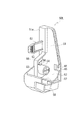
図6は可動ベース部100を示す斜視図である。
可動ベース部100は合成樹脂製で、主制御装置22(基板ボックス30)の下端壁を受ける載置部102と、載置部102の左右外側に上下にわたって形成された側部ブロック104(104L、104R)と、載置部102の後端から上下に延びた後壁部106と、載置部102の前端縁から下方に延びる前壁部105と、前壁部105と後壁部106とに連なって載置部102と平行に延びる下壁部107を有している。載置部102と下壁部107の間は複数の区画からなる封止部108となる。
FIG. 6 is a perspective view showing the
The
なお、封止部108における第1区画109aは基板ボックス30を構成する第1ボックス200と第2ボックス201間を封止キャップで封止した第1の封止結合部70(後掲の図8参照)を収容する部分であり、第2、第3区画109b、109cはそれぞれ基板ボックス30と可動ベース部100間を封止する第2の封止結合部71のための封止構造形成部75bを備えている。第4区画109dは第1ボックス200と第2ボックス201間を不図示の封止ピンで封止する第3の封止結合部72(図8参照)を収容する部分である。
The
側部ブロック104は、載置部102から上方に延びてその全長にわたって後縁が後壁部106の左右両端に連なっている側端壁112と、載置部102より下側で外方(側部ブロック104Lでは左方、側部ブロック104Rでは右方)に向けて開口する軸筒115を備える軸受部114と、側端壁112の前縁から内方に延びる保持壁116(116L、116R)と、側端壁112より外方に張り出した取っ手兼係止部120(120L、120R)とを有する。
The side block 104 includes a
側端壁112の上端は、載置部102に載置した基板ボックス30の高さの略中間位置まで達する高さに設定されている。
保持壁116は側端壁112に沿った一定幅のフランジ状である。
側端壁112、保持壁116および後壁部106とでコ字形の溝118(118L、118R)を形成している。溝118の下端は載置部102より一段高い段差面119となっている。
取っ手兼係止部120は封止部108の前壁部105と面一に連なった前壁121を備え、前壁121には指掛け部123が形成されるとともに、固定ベース部50の姿勢保持部62の爪63と係止する係止孔124が設けてある。
The upper end of the
The holding wall 116 has a flange shape with a constant width along the
The
The handle / engaging portion 120 includes a
軸受部114の下半部は軸筒115に沿った円筒面をなし、上半部前面は前壁部105の延長部となり、後面は以下に述べる後壁部106の凹部、すなわち膨出部106a部分の後面の延長部となっている。
軸受部114には、軸筒115の斜め後上方に軸筒115の端面よりも外方に突出する係止バー134を備えている。係止バー134は、可動ベース部100を傾倒姿勢位置にしたとき固定ベース部50の第1回動ストッパ56に当接するものである。
The lower half portion of the bearing
The bearing
後壁部106における側端壁112に連なる所定領域は、外面(後面)に固定ベース部50の縦壁51を逃げる凹部を形成するため、内側へオフセットしており、その分だけ溝118に及ぶ膨出部106aとなっている。
なお、後壁部106の上縁は左右の所定範囲が側端壁112の上端と同じ高さで、左右方向中央部ではより低い直線状で、その間は傾斜しており、後方から見たとき谷形状を呈している。後壁部106の上縁端面には複数の突起132が形成されている。
とくに図示しないが、後壁部106から下壁部107にかけては軸筒115と同心の円筒面となっている。
The predetermined region connected to the
Note that the upper edge of the
Although not particularly illustrated, a cylindrical surface concentric with the
封止部108の左右両端には、前壁部105から後壁部106までの貫通穴129が形成されている。この貫通穴129は、軸筒115に固定ベース部50のヒンジ軸54を挿入し姿勢保持部62の爪63を係止孔124に係止させて、後壁部106を固定ベース部50の縦壁51に沿わせたとき、固定ベース部50のネジ挿通穴66に整合するように設定されている。
載置部102には貫通穴129に開口する連通穴130が後壁部(膨出部106a)に接して設けてあり、後述する基板ボックス30の突片40を受け入れるようになっている。
Through
The mounting
右側の側部ブロック104Rの保持壁116Rは、外形が厚肉で、その前端面は取っ手兼係止部120Rの前壁121と面一となっている。
保持壁116Rの前端面に開口する凹部127の底壁には、基板ボックス30の固定用ネジ孔39に対応させて、ネジ挿通穴128(図7参照)が設けてある。
右側の側部ブロック104Rにおける溝118Rは前後幅一定である。
The holding
A screw insertion hole 128 (see FIG. 7) is provided on the bottom wall of the
The
本実施の形態では、後述するように、基板ボックス30の前壁31の左端部にケーブル27のコネクタ28と接続する回路基板のソケット挿通穴203が設けられ、基板ボックス30と側部ブロック104Lの境界に跨ってコネクタカバー300の取付部が形成される。このため、左側の側部ブロック104Lは右側の側部ブロック104Rとは一部異なる構造を有する。
図7は左側の側部ブロック104Lを示す斜視図である。
側部ブロック104Lにおいては、保持壁116L自体は薄板状で、その前端面は取っ手兼係止部120Lの前壁121よりも後方へ退避している。したがって、保持壁116Lの前端面は取っ手兼係止部120Lの側壁122から内方へ延びる形態となっている。
In the present embodiment, as will be described later, a circuit board
FIG. 7 is a perspective view showing the
In the
左側の保持壁116Lは上半部116aが下半部116bに対して前方へわずかにオフセットしており、このため溝118Lは相対的に上半部の前後幅が下半部よりも広くなっている。薄板状の下半部116bは載置部102まで延びている。
保持壁116Lの上半部116aの前端面上にはケーブル押え140が一体に設けられ、下半部116bには右側の保持壁116Rと同様に、基板ボックス30の固定用ネジ孔39に対応させて、ネジ挿通穴128が設けてある。
さらに下半部116bの前端面上には第1の剥し方向係止部220eと第2のスライド方向係止部240が設けてある。
ケーブル押え140や各係止部220e、240については追って詳細に説明する。
In the
A
Further, a first peeling
The
以上の構成を有する台座装置25は、まず、固定ベース部50を、そのヒンジ軸54を可動ベース部100の軸筒115に挿入して、可動ベース部100を左右から挟む形に組み付ける。そして、固定ベース部50の各フック60をそれぞれ背板2c側に設けられた不図示のフック受けに係止させる。
つぎに、相対的に可動ベース部100の起立姿勢位置、すなわち可動ベース部の後壁部106と固定ベース部50の縦壁51を重ねた状態にすると、可動ベース部100の貫通穴129が固定ベース部50のネジ挿通穴66に重なるから、ドライバで貫通穴129を通してネジ挿通穴66から筐体本体2の背板2c内側の対応する箇所に予め設けられているナット部にネジをねじ込んで固定ベース部50を背板2cに固定する。
In the
Next, when the standing posture position of the
背板2cの背面側からも、背板2cに形成した不図示のネジ挿通穴を通してネジを縦壁51の裏面に開口するネジ孔にねじ込む。これにより、固定ベース部50は背板2cに対して前方および後方の両方から固定されるので、前方または後方の一方からのみでは背板2cから取り外すことができない。
可動ベース部100はこのように背板2cに固定された固定ベース部50のヒンジ軸54を軸筒115に挿入されて支持されているので、背板2cに固定された固定ベース部50から取外すことはできない。
Also from the back side of the
Since the
次に、主制御装置22の構成について説明する。
図8は主制御装置22を前方から見た外観斜視図、図9は主制御装置22を後方から見た斜視図である。
基板ボックス30は表側の第1ボックス200と裏側の第2ボックス201とからなっている。
基板ボックス30の外形の基本前後幅(基本厚さ)は、可動ベース部100における前壁部105の前面から後壁部106の後面間の距離に一致させてある。
主基板23(図11参照)は、ネジなどにより例えば第1ボックス200の内側に取り付けられて基板ボックス30の内部に収容される。主基板23上には、配線パターンが形成されるとともに、CPUやROM等のICチップを含む各種電子部品等が実装され、外部のケーブル27との接続のためのソケット45が固定されている。
Next, the configuration of the
FIG. 8 is an external perspective view of the
The
The basic front-rear width (basic thickness) of the outer shape of the
The main board 23 (see FIG. 11) is attached to the inside of the
基板ボックス30の前壁31には、左端部に主基板23上のソケット45を挿通させるためのソケット挿通孔203が形成され、右端部にはリセットボタン等をカバーしてドア205を備える操作ボタンカバー部204が膨出している。図8では、ソケット45のロックレバー46が直立位置でソケット挿通孔203から突出している状態が示されている。
第1ボックス200と第2ボックス201間は不図示の係止爪やネジ等で結合されるとともに、初期状態では基板ボックス30の下端部において、例えば特願2010−158199に開示された第1封止部34と同様の、封止キャップを用いた第1の封止結合部70により結合状態が封止される。
The
The
なお、基板ボックス30の下端部には、第1の封止結合部70に隣接して、可動ベース部100との結合を封止するための第2の封止結合部71(図3参照)を形成する封止構造形成部75a、および第1ボックス200と第2ボックス201間の結合を封止するための第3の封止結合部72(図3参照)を形成する封止構造形成部76などが設けてある。
第2の封止結合部71は内部点検等のため第1の封止結合部70を破壊して封止解除した後の再封止に使用するものであって、可動ベース部100との封止によって同時に第1ボックス200と第2ボックス201間の結合も封止する。
In addition, the 2nd sealing coupling |
The second
第3の封止結合部72は複数の第2の封止結合部71を順次に使用し尽くしたあと、主基板23の検査等が必要になった場合には、主基板23を基板ボックス30ごとメーカーへ返送できるように基板ボックス30自体を封止するものである。
封止構造形成部75a、76は例えば特願2010−158199に開示された第2、第3封止部36、38における筒状体255と同様に筒状をなし、主基板ユニット20専用に準備された封止ピンを使い回しして挿入することにより封止を行う。
ここでは、これらにより基板ボックス30自体、あるいは基板ボックス30と可動ベース部100間が封止結合されることのみ述べて、その詳細説明は省略する。
When the third
The sealing
Here, only the fact that the
基板ボックス30は、左右の側壁35(35L、35R)間の長さを可動ベース部100の左右の保持壁116L、116Rの各内側端縁間の距離に対応させてある。
基板ボックス30の左右両端の上部には、それぞれ側壁35よりも左右外方に張り出した側方張出し部37(37L、37R)を有する。さらに、側方張出し部37の下側には、側壁35から同様に左右外方に張り出すが、側方張出し部よりも少ない張り出し量で下端壁34近くまで延びる被保持部38(38L、38R)を有している。
In the
On the upper portions of the left and right ends of the
側方張出し部37L、37Rを含んだ基板ボックス30の左右方向長さは可動ベース部100の左右の側部ブロック104の側端壁112の外端面間の距離に一致するよう設定され、また、被保持部38は側部ブロック104の各溝118にそれぞれ整合して嵌まり込むよう設定されている。
なお、右側の被保持部38Rの前端面は上下に渡って平坦面であるが、左側の被保持部38Lの前端面は上下方向中間位置に段差を有して、上半部が下半部よりも前方へオフセットしている。これは、保持壁116Lの上半部116aおよび下半部116bに対応するものである。
The length in the left-right direction of the
The front end surface of the right held
そして、載置部102に基板ボックス30を載置したとき、基本的に可動ベース部100から露出した基板ボックス30の外壁面と可動ベース部100の外壁面とが面一に連なるようになっている。
このため、基板ボックス30の後壁32も可動ベース部100の後壁部106および膨出部106aに対応して基本外形から退避したオフセット領域42a、42bを有している。
後壁32のオフセット領域42aにおける可動ベース部100の後壁部106の上縁に対向する周面には、突起132に対応する係止穴43が形成されている。
また、被保持部38の下端もオフセットさせて、下端壁34からの高さが可動ベース部100における溝118の段差面119の高さに対応させてある。
When the
For this reason, the
A locking
In addition, the lower end of the held portion 38 is also offset so that the height from the
右側の側方張出し部37Rは基本前後幅のまま張り出し、右側の側部ブロック104R周りの各壁部外面はその境界部分で面一となるようにしてある。
一方、左側の側方張出し部37Lの上半部は基本前後幅のままであるが、下半部は後述する切欠き212により、基本前後幅より薄くなっている。切欠き212はソケット45に接続されたコネクタ28から延びるケーブル27を引き出すケーブル通路24の一部を形成するが、これについては後述する。
前述のように、載置部102に基板ボックス30を載置したとき、可動ベース部100から露出した基板ボックス30の外面と左側の側部ブロック104Lまわりの各壁部外面との間でもその境界部分で基本的に面一となるが、ただし、保持壁116Lの前端面上には第1の剥し方向係止部220e、第2のスライド方向係止部240、ケーブル押え140などが形成されているので、保持壁116Lまわりでは単純に面一とはなっていない。
The right
On the other hand, the upper half of the left
As described above, when the
基板ボックス30の下端壁34の左右両端には、突片40が形成されている。突片40は下端壁34の後端縁から下方に延びており、基板ボックス30が可動ベース部100に載置されたとき載置部102の連通穴130に進入して貫通穴129を塞ぐように設定される。これによって基板ボックスが設置された状態で固定ベースが外されてしまうことを防止することができる。
主基板ユニット20(基板ボックス30)は固定ベース部50L、50Rを介してスロットマシン1の筐体内に支持された可動ベース部100に載置され、この載置状態においてソケット45にケーブル27のコネクタ28が接続される。そしてこの後、コネクタ接続部にコネクタカバー300が取り付けられる。
ここで、コネクタ接続部とはコネクタ28が挿し込まれたソケット45まわりを指し、後述するソケット挿通孔203およびロックレバー46を含む。
The main board unit 20 (board box 30) is placed on the
Here, the connector connecting portion refers to the periphery of the
つぎに、コネクタカバーの取り付け部について説明する。
図10はコネクタカバー300の取り付け部を示す部分拡大正面図、図11は図10におけるA−A部断面図である。
前述のように、コネクタカバー300はソケット45とケーブル27のコネクタ28との接続部をカバーするもので、その取り付け部はソケット挿通孔203を囲んで基板ボックス30と可動ベース部100に跨って形成されたカバー嵌め込み領域210として区画されている。
なお、ここでは可動ベース部100を支持している固定ベース部50は図示省略している。
Next, the attachment part of the connector cover will be described.
10 is a partially enlarged front view showing a mounting portion of the
As described above, the
Here, the fixed base 50 supporting the
カバー嵌め込み領域210の平面形状はコネクタカバー300の後述するベース305の外周縁形状に対応し、可動ベース部100にかかる領域を含んで矩形をなしている。
まず、基板ボックス30においては、カバー嵌め込み領域210は前壁31の表面(前面)からの底壁211の深さがコネクタカバー300の後述のベース305の板厚に対応する凹部として、ソケット挿通孔203を囲んで形成してある。
カバー嵌め込み領域210は前壁31の上下にわたって延びており、上端は上端壁33を残し、下端は下端壁34を抜けて素通しとなっている。なお、左側の側壁35Lに沿う部分は当該側壁で切り落とされている。
The planar shape of the cover
First, in the
The cover
コネクタカバー300との係止のため、カバー嵌め込み領域210の底壁211には第1の剥し方向係止部220(220a、220b、220c、220d、220e)を設けてある。ここでは、第1の剥し方向係止部220a、220b、220d、220cが基板ボックス30側におけるソケット挿通孔203の右側の上端部、中間部、下端近傍、そしてソケット挿通孔203の左側の上端部に配設され、第1の剥し方向係止部220eが可動ベース部100側の下端近傍に配設されている。
また、とくに図11に示すように、底壁211には、ソケット45の上下長さに対応する幅の切欠き212が、ソケット挿通孔203から側壁35Lおよび側方張出し部37L下半部それぞれの外方端面に開口するまで形成されている。すなわち、切欠き212は側壁35Lと側方張出し部37Lの双方に跨り、カバー嵌め込み領域210の底壁211より深いケーブル通路24の一部となる。
なお、図10において、符号78は保持壁116のネジ挿通穴128から基板ボックス30の固定用ネジ孔39に締め込んで可動ベース部100と基板ボックス30を固定したネジである。
In order to lock the
In particular, as shown in FIG. 11, a
In FIG. 10,
図12は第1の剥し方向係止部を拡大して示し、(a)は底壁211上端部の第1の剥し方向係止部220aの正面図、(b)は(a)におけるB−B部断面図、(c)は(a)におけるC−C部断面図である。図12の(d)は底壁211下端近傍の第1の剥し方向係止部220dにおける(b)に相当する断面図である。
第1の剥し方向係止部220aは、所定幅を有して底壁211の表面(前面)から所定の深さまで形成された幅広溝部221aと、幅広溝部221aに同幅で連通する空間222の前面開口部をスリット223を残して覆った引掛部224aとからなっている。スリット223はコネクタカバー300における後述の係止部315のリブ317との干渉を逃げるためのものであり、ソケット挿通孔203と並行に上下方向に延び、幅広溝部221aのソケット挿通孔203側の辺に沿っている。
また、幅広溝部221aの上下方向サイズはコネクタカバー300の係止部315aが進入可能に設定してある。
12 is an enlarged view of the first peeling direction locking portion, (a) is a front view of the first peeling
The first peeling
In addition, the vertical size of the
引掛部224aは上下方向に沿って厚さ一定で、その表面は底壁211と面一であるとともに、裏面と幅広溝部221aの溝底225aとは高さ(前後)方向に係止部315aの後述する引掛部316aの進入を可能とする所定の間隙を有している。
引掛部224aは、コネクタカバー300の引掛部316aを幅広溝部221aから進入させて当該引掛部224aの裏面側に位置させたとき、引掛部316aの剥し方向(底壁211に対する垂直方向)への抜けを阻止する。
なお、幅広溝部221aに連通する空間222はスリット223と引掛部224aの成形型を通すため、溝底225aが切欠かれている。
The
The hooking
Note that a
とくにソケット挿通孔203右側の上端部と中間部に設けた第1の剥し方向係止部220a、220bの間には、図10にも示すように、各スリット223を結ぶ線上にスリット223と同幅の細溝213aが形成されて、一方の幅広溝部221aから他方の空間222に連通している。細溝213の深さは幅広溝部221aの深さと同じになっており、コネクタカバー300の後述する延長リブ318aを受け入れ可能となっている。
第1の剥し方向係止部220aと220bは同一形態であるが、第1の剥し方向係止部220cは220aに対して左右対称となっている。図10に示すように、第1の剥し方向係止部220cの空間には短い細溝213bが連なっている。
第1の剥し方向係止部220dは、図12の(d)に示すように、引掛部224dの下端の厚さが引掛部224aと同じで上方に行くにしたがって厚さが増大して、裏面が直線的な傾斜面となっている点が異なり、その他は引掛部224aと同じである。コネクタカバー300の引掛部316dが引掛部224dの裏面側に位置して係止する。
In particular, between the upper end portion on the right side of the
The first peeling
As shown in FIG. 12D, the first peeling
下端近傍の第1の剥し方向係止部220dの上方に隣接して、さらに第1のスライド方向係止部230を設けてある。
図13は第1のスライド方向係止部230を拡大して示し、(a)は正面図、(b)は(a)におけるD−D部断面図、(c)は(a)におけるE−E部断面図である。
第1のスライド方向係止部230は、底壁211に第1の剥し方向係止部220aの幅広溝部221aと同様の幅をもって底壁211の右側辺縁に沿って形成した幅広溝部231内の右側側壁に爪部232を形成して構成されている。
A first sliding
FIG. 13 is an enlarged view of the first sliding
The first sliding
爪部232は上端に幅広溝部231の溝幅中間まで延びた係止面233を有し、その下側に右側側壁に向かう傾斜面234を有している。係止面233は上下方向に対して垂直である。
爪部232の係止面233から傾斜面234にわたる前縁は面取りされている。
幅広溝部231の深さは幅広溝部221aよりも深く、爪部232は幅広溝部231の深さの中間に位置しており、爪部232と溝底236とは高さ(前後)方向に所定の間隙を有している。
なお、溝底236から所定の間隙を有する爪部232の成形型のため、溝底236は爪部232に対応する部分が切欠かれている。
The
A front edge extending from the locking
The depth of the
The
つぎに可動ベース部100においては、保持壁116Lの上半部116aの前端面が、可動ベース部100に基板ボックス30を載置したときの切欠き212の底面と面一となるように設定してある。これにより、上半部116aの前端面と切欠き212とでケーブル通路24が形成される。
Next, in the
ケーブル押え140は、図7に示されるように、保持壁116Lの上半部116a前端面の下端から前上方へ斜めに立ち上がった脚壁141と、脚壁141の前端から上半部116aと平行に保持壁116Lの上端に対応する位置まで延びる押えバー142とからなっている。脚壁141の近傍には押えバー142の倒れを防止する支持脚143が形成されている。
図14は図10におけるW−W部断面図である。
脚壁141の上端(前端)部には第2の剥し方向係止部として下方に開口する係止穴228が形成され、コネクタカバー300の後述する係止片314が進入可能となっている。
As shown in FIG. 7, the
14 is a cross-sectional view taken along the line WW in FIG.
The upper end (front end) portion of the
保持壁116Lの下半部116bの前端面上にはネジ挿通穴128より下方に第2のスライド方向係止部240が設けられ、さらにその下方には前述の第1の剥し方向係止部220eが設けてある。
図15は第2のスライド方向係止部240を拡大して示し、(a)は正面図、(b)は(a)におけるF−F部断面図、(c)は(a)におけるG−G部断面図である。
第2のスライド方向係止部240は、上端に上下方向に垂直な係止面243を有し、その下側に内方へ傾斜する傾斜面244を有する爪部242で構成されている。係止面243は下半部116bの内方端縁から下半部116bの幅の中間まで延びている。
A second sliding
FIG. 15 is an enlarged view of the second sliding
The second sliding
第2のスライド方向係止部240の下方には、取っ手兼係止部120Lの側壁122に連なり下半部116bから全幅にわたって前方へ立ち上がった2つの横支持壁246、247(図7参照)が上下方向に所定の間隔を置いて設けてある。
横支持壁246の上側には、当該横支持壁246の一部を下辺とする矩形枠形状のベース受け部250が下半部116bの内方端縁に沿って形成され、その上端が爪部242の傾斜面244の下端に連なっている。
Below the second sliding
On the upper side of the
図16は第1の剥し方向係止部220eを拡大して示し、(a)は正面図、(b)は(a)におけるH−H部断面図、(c)は(a)におけるJ−J部断面図である。
第1の剥し方向係止部220eは基板ボックス30側の第1の剥し方向係止部220dの引掛部と同じ引掛部224dを側壁122から内方へ延ばしている。
第1の剥し方向係止部220eの引掛部224dは第1の剥し方向係止部220dの引掛部224dと上下方向で互いに同じ高さとなる位置に設定してある。第1の剥し方向係止部220eの引掛部224dの上端は横支持壁246に連なっている。
そして、2つの横支持壁246、247の間が第1の剥し方向係止部220eの幅広溝部221eを構成し、下半部116bの前端面がその溝底225eとなる。引掛部224dの裏面と溝底225eの間は十分な間隙があり、コネクタカバー300の係止部315eの後述する引掛部316dの進入が可能である。
FIG. 16 is an enlarged view of the first peeling
The first peeling
The hooking
The width between the two
第1の剥し方向係止部220eの引掛部224dを含み、上述した爪部242、横支持壁246、247およびベース受け部250の前端面はいずれも可動ベース部100に基板ボックス30を載置したときの基板ボックス30におけるカバー嵌め込み領域210の底壁211と面一となるように設定してある。また、側壁122にも引掛部224d、横支持壁246、247等と同じ高さで段差122aを形成してある。
可動ベース部100においては、保持壁116L(上半部116aおよび下半部116b)における側壁122より内方側がカバー嵌め込み領域210の一部となる。
The
In the
図7に示されるように、載置部102の両端と段差面119との間には接続壁117が設けられ、接続壁117は保持壁116L(下半部116b)を越えて載置部102の前端部分まで延び、下半部116bを越えた部分の上縁は下側の横支持壁247の内方端に連なっている。
そして、図10におけるK−K部断面図である図17に示すように、基板ボックス30および可動ベース部100のカバー嵌め込み領域210に対応する前壁部105から取っ手兼係止部120Lの前壁121にかけて、載置部102の前端縁およびその外方(左方)への延長線上の角部が切り欠かれて、傾斜面252となっている。
接続壁117の前端面は傾斜面252と同じ傾斜でカバー嵌め込み領域210の底壁211と同じ高さにある横支持壁247の前端面に向かっている。
As shown in FIG. 7, a
Then, as shown in FIG. 17 which is a sectional view taken along the line KK in FIG. 10, the front wall of the handle /
The front end surface of the
図18はコネクタカバー300を示し、(a)は正面図、(b)は左側面図、(c)は右側面図、(d)は下方から見た端面図である。図19はコネクタカバー300の裏面図である。図20は各部の断面を示し、(a)は図18の(a)におけるL−L部、(b)は図18の(a)におけるM−M部の断面図、(c)は図19におけるN−N部の断面図である。
コネクタカバー300は外縁が縦細の矩形をなすベース305からコネクタ収容部306を膨出させている。コネクタ収容部306は側辺が不等長の台形をなす横断面を有している。ベース305の下端縁は裏面側が面取りされて傾斜面345となっている。
18A and 18B show the
The
コネクタカバー300は下部において微小なスリットにより長尺の第1部301とそれぞれ短尺の第2部302および第3部303に3分割され、ベース305の左右の側縁からそれぞれ延びる耳片307、308によって連結されている。
コネクタカバーの第1部301には、コネクタ収容部306に連なって、可動ベース部100のケーブル押え140に対応させたケーブル押え収容部310が膨出させて形成されている。
The
In the
各耳片307、308はベース305の第1部301の分割端近傍から第3部303の分割端近傍にわたる側縁に沿ってフランジ状に形成されているが、とくに、左側の耳片307はベース305から前方へ垂直に延び、右側の耳片308は先端がコネクタ収容部306から離間する方向に傾斜して延びている。
第1部301の分割端と第3部303の分割端にはそれぞれ外面側に突のビード343が設けられて、断面形状保持の補強となっている。
耳片307、308には第1部301から第3部303の各部との接続部分の間に切欠き309が形成されて、当該切欠き309で細幅となった部分が易破断部となっている。
Each of the
Protruding
In the
コネクタカバー300のベース305の裏面には、カバー嵌め込み領域210における第1の剥し方向係止部220に対応する係止部315(315a、315b、315c、315d、315e)と、第2の剥し方向係止部(係止穴228)に対応する係止片313と、第1のスライド方向係止部230に対応する係止部320と、第2のスライド方向係止部240に対応する係止部330が形成されている。
On the back surface of the
図21は剥し方向にかかる係止部315aを示し、(a)は図19における係止部315aの拡大図、(b)は(a)におけるP−P矢視図、(c)は(a)におけるQ−Q部断面図である。
係止部315aは、ベース305から後方へ延びる片vとその後端から上方へ延びる片wとからなるL字状の引掛部316aを有し、その内方側(コネクタ収容部306側)をベース305から上方へ延びる片wまで立ち上げたリブ317に接続して構成されている。上方へ延びる片wとベース305裏面との間隙は第1の剥し方向係止部220aの引掛部224aの厚さに対応させてあり、リブ317の左右方向位置はスリット223に対応させてある。
係止部315bは係止部315aと同一、係止部315cは係止部315aと左右対称である。
FIG. 21 shows the locking
The locking
The locking
図19に示すように、係止部315aと315bの間にはこれらの係止部のリブ317を結ぶ上下線上に位置してベース305の側縁に沿った延長リブ318aが接続している。
係止部315cにも後方へ延びる片vより下方に所定長さの延長リブ318bが接続している。
なお、係止部315dにおいては、図21の(b)に対応する図22に示すように、引掛部316dの上方へ延びる片wをベース305裏面との間隙が大きくなるように傾斜させてある。この傾斜は第1の剥し方向係止部220dの引掛部224d裏面の傾斜に対応させてある。その他は図21に示した係止部315aと同じである。
係止部315eは係止部315dと左右対称である。
As shown in FIG. 19, an
An
In the locking
The locking
図23はスライド方向にかかる係止部320を示し、(a)は図19における係止部320の拡大図、(b)は(a)におけるR−R矢視図、(c)は(b)におけるS−S部断面図、(d)は(b)におけるT−T部断面図である。
係止部320は、ベース305の長手方向(上下方向)と平行にベース305から後方へ延びた矩形の縦壁部321に、第1のスライド方向係止部230の爪部232と係止するための矩形の係止穴325を形成して構成され、縦壁部321は弾性変形により先端側がねじれ、および板厚方向に曲げ可能となっている。
FIG. 23 shows the locking
The locking
縦壁部321は第1のスライド方向係止部230の幅広溝部231の右側側壁に沿うように配置され、外方側の上縁および先端縁にそれぞれ面取りにより傾斜面322、323を形成してある。とくに上辺の傾斜面322は、(c)に示すように、上下方向に対して浅い角度になっている。
また、係止穴325の先端縁(ベース305から遠い辺)には、外方側(コネクタ収容部306と反対側)に略45°の傾斜面326を形成してある。
The
Further, an
図24はスライド方向にかかる係止部330を示し、(a)は図19における係止部330の拡大図、(b)は(a)におけるU―U矢視図、(c)は(a)におけるV−V部断面図である。
係止部330は、ベース305から後方へ立ち上がったあと上方へ延びる弾性片部331と、弾性片部の上端に形成された爪332とから構成されている。
弾性片部331はベース305に対して垂直の板状で、その前縁とベース305裏面との間に間隙をもっている。弾性片部331が撓んで爪332部が左右方向に変位可能となっている。
FIG. 24 shows the locking
The locking
The
爪332は内方(コネクタ収容部306側)を向いており、第2のスライド方向係止部240の爪部242と係止するための上下方向に垂直な係止面333と、その内端から外方へ傾斜する傾斜面334を有する。
弾性片部331の内側面は第2のスライド方向係止部240の爪部242における係止面243から傾斜面244に移行する点に対応するように設定してある。
ベース305裏面から弾性片部331の後縁までの高さhは、カバー嵌め込み領域210の底壁211から保持壁116Lの下半部116bの前端面までの深さよりも小さく設定してある。
The
The inner side surface of the
The height h from the back surface of the base 305 to the rear edge of the
つぎに、ケーブル押え収容部310の下端壁310bからは、図20の(a)に示すように、係止片313がケーブル押え収容部310内に向けて前壁310aと間隙をもって上方に延びている。
係止片313は可動ベース部100におけるケーブル押え140の係止穴228に対応させてあり、係止穴228への進入を容易にするため、先端の前角は傾斜面314としてある。
なお、前壁310aと間隙をもった係止片313をコネクタカバー300内に形成する成形型のため、ケーブル押え収容部310はその前壁310aから下端壁310bにかけて部分的に切り欠かれている。
Next, as shown in FIG. 20A, the
The
In addition, the cable
コネクタカバー300の左側の側辺部はケーブル通路24を横切る間、ベース305は底壁211と当接せず宙に浮くので、とくに図19に示されるように、ベース305の裏面には側縁に沿ってケーブル押え収容部310から延長リブ318b近傍にわたるビード342を設けて剛性を高くしている。また、ベース305の側縁に沿って前方へ立ち上がっているケーブル押え収容部310の側壁310c(図20の(b)参照)もベースの剛性を高めている。
Since the
以上説明した各係止部はコネクタカバー300がカバー嵌め込み領域210に嵌め込まれた状態、すなわちコネクタカバー300の上端がカバー嵌め込み領域210の上縁(基板ボックスの上端壁33)に当接する位置において、カバー嵌め込み領域210の対応する係止部と係止するように関係付けられる。
すなわち、係止部315a〜315cはその各引掛部316aが第1の剥し方向係止部220a〜220cの各引掛部224aと重なり、係止部315d、315eはその各引掛部316bが第1の剥し方向係止部220d、220eの各引掛部224dと重なり、係止部320はその縦壁部321の係止穴325が第1のスライド方向係止部230の爪部232と係止関係となる。
また、係止部330はその爪332の係止面333が第2のスライド方向係止部240の爪部242の係止面243と係止関係となる。
Each of the locking portions described above is in a state where the
That is, the latching
In addition, the locking
なお、第1、第2のスライド方向係止部230、240に対応する係止部320と係止部330はコネクタカバー300の上下方向において略同じ高さに配置され、コネクタカバーの第2部302は、上述した係止部のうちこの係止部320と係止部330とを含み、他の剥し方向係止部220等に対応する係止部を含まないように設定してある。
図20の(c)に示すように、第2部302にはコネクタ収容部306を横切る横隔壁347が設けてある。横隔壁347の後端縁はベース305の裏面と面一とされている。
The locking
As shown in FIG. 20C, the
横隔壁347の上下方向位置は、カバー嵌め込み領域210へのコネクタカバー300の取り付け完了位置において、ソケット45に挿し込まれたコネクタを抜け止めロックして底壁211に対する直立位置になったロックレバー46の下方に近接するように設定されている。これにより、コネクタカバー300の取り付け過程において、横隔壁347がロックレバー46の開放状態である倒れ位置からロック状態の直立位置までの回動軌跡の範囲内を横切ることになる。
なお、横隔壁347はコネクタカバー300がカバー嵌め込み領域210に嵌め込まれる過程でロックレバー46の回動軌跡を横切るように設定されるもので、第2部302がロックレバー46の回動軌跡上に位置しない場合には、回動軌跡範囲をカバーする第1部301または第3部303に設けてもよい。
The
The
以上の構成を備えたコネクタカバー300は、次の要領でカバー嵌め込み領域210に嵌め込む。
まず、傾倒姿勢位置とした可動ベース部100に基板ボックス30を載置する。
基板ボックス30の下端壁34が載置部102上に着座するとともに、第1、第3の封止結合部70、72や封止構造形成部75a、76などが第1区画109a〜第4区画109dに収容される。また、突片40が連通穴130に進入する。
つぎに、可動ベース部100の保持壁116のネジ挿通穴128からネジ78を基板ボックス30の固定用ネジ孔39に締め込んで、基板ボックス30を可動ベース部100に固定する。この場合、可動ベース部100を起立姿勢にして行うと作業が容易となる。
基板ボックス30が可動ベース部100に固定されると、両者にわたるカバー嵌め込み領域210がコネクタカバー300嵌め込み可能に準備されたことになる。
The
First, the
The
Next, the
When the
固定ベース部50の姿勢保持部62と可動ベース部100の係止孔124を係止させて可動ベース部100を起立姿勢位置に保持した状態で、ケーブル27のコネクタ28を基板ボックス30のソケット45に挿し込んで接続する。
この際、ケーブル27はケーブル押え140の裏側に潜らせ、ケーブル通路24を通るように配索する。
なお、コネクタ28はロックレバーが倒れてソケット45の口が開いた状態で挿し込む。コネクタ28がソケット45に確実に挿し込まれるとその過程においてロックレバーを回動させ、正規の接続状態ではロックレバーが直立位置となってロックされる。
The
At this time, the
The
このあと、コネクタカバー300を取り付ける。
ここではまず、コネクタカバー300の上下をカバー嵌め込み領域210の上下方向に合わせ、コネクタカバー300裏面の係止部315が第1の剥し方向係止部220の各幅広溝部221(221a、221e)上に位置するように所定量ずらせて対向させる。
そして、ベース305を底壁211に押し付けて係止部315を幅広溝部221内に沈ませ、それからその押し付け状態を維持したままコネクタカバー300を上方へスライドさせて、係止部315の引掛部316(316a、316d)をカバー嵌め込み領域210の引掛部224(224a、224d)の裏面側に進入させる。
Thereafter, the
Here, first, the upper and lower sides of the
Then, the
ここで、コネクタ28がソケット45に対して正規の接続状態に挿し込まれていれば、図25の(a)に示すように、ロックレバー46が直立位置にあり、コネクタカバー300はその横隔壁347がカバー嵌め込み領域210の底壁211上を滑って、障碍なくスライドする。
なお、図25および次の図26には、理解を容易にするため、断面は異なるがコネクタ接続部と係止部を重ねて示している。
一方、コネクタ28のソケット45への挿し込みが不十分で正しく接続されていないときは、ロックレバー46が回動軌跡の途中にあり、(b)に示すように、横隔壁347がロックレバー46と干渉して係止部315を幅広溝部221内に沈ませることができず、結果として各引掛部316を引掛部224の裏面側に進入させることができない。
したがって、コネクタ28が正規の接続状態になければコネクタカバー300を取り付けることはできないから、あらためてコネクタ28の挿し込みをやり直し、必要に応じて最後に手でロックレバー46を直立位置まで起こしてロックする。
Here, if the
In FIG. 25 and the next FIG. 26, for easy understanding, the connector connecting portion and the locking portion are shown in an overlapping manner although the cross-sections are different.
On the other hand, when the
Accordingly, since the
なお、ベース305を底壁211に押し付けて引掛部316を幅広溝部221内に位置させた状態において、コネクタカバー300はその下端部が底壁211よりも前方に高いカバー嵌め込み領域外に乗っているので、コネクタカバー300の下部は湾曲し、ベース305裏面が底壁211から若干浮くことになる。
ここで、コネクタカバー300の下端部近傍に位置する係止部315d、315eの各引掛部316dは、その上方へ延びる片wが傾斜してその上端とベース305の裏面との間隙が拡がっているので、コネクタカバー300を上方へスライドさせる際、他位置の引掛部315a等と同様に支障なくカバー嵌め込み領域210の引掛部224dの裏面側に進入することができる。
なお、可動ベース部100の載置部102の角部を切り欠いた傾斜面252により、コネクタカバー300の湾曲の程度をできるだけ抑えてベース305裏面と底壁211間の間隙が小さくなるようにしている。
In the state where the
Here, in each hooking
The
コネクタカバー300のスライドの間、係止部320は、その縦壁部321がねじれながら、上縁の傾斜面322がカバー嵌め込み領域210における爪部232の傾斜面234に乗り上げていく。
係止部330は、その弾性片部331が撓みながら、爪332の傾斜面334がカバー嵌め込み領域210における爪部242の傾斜面244に乗り上げていく。
また、ケーブル押え収容部310内に延びる係止片313がケーブル押え140の係止穴228に進入していく。
During the sliding of the
In the locking
Further, the
そして、コネクタカバー300をその上端縁がカバー嵌め込み領域210の上縁に当接するまでスライドさせると、コネクタカバー300はカバー嵌め込み領域210に嵌め込まれた状態の取り付け完了位置となり、ベース305が湾曲から平坦な状態へ戻るとともに、コネクタカバー300とカバー嵌め込み領域210の各係止部は互いに係止状態となる。
Then, when the
すなわち、図26に示すように、係止部315a(および315b、315c)の引掛部316aが第1の剥し方向係止部220a(および220b、220c)の引掛部224aの裏面側に重なって互いに係止し、係止部315d(および315e)の引掛部316dが第1の剥し方向係止部220d(および220e)の引掛部224dの裏面側に重なって、コネクタカバー300の引き剥がし方向の抜けが規制される。
コネクタカバー300の下端部近傍の係止部315d、315eの引掛部316dは上方へ延びる片wが傾斜してその先端とベース305裏面間が開いているが、取り付け完了位置では上方へ延びる片wとベース裏面間の間隙が引掛部224dの板厚形状に整合しているので、ガタの発生はない。
さらに、図27に示すように、コネクタカバー300の係止片313は係止穴228に進入してケーブル押え140に係止し、コネクタカバー300の引き剥がし方向の抜けが規制される。
That is, as shown in FIG. 26, the hooking
The
Further, as shown in FIG. 27, the
また、図28の(a)に示すように、係止部320の縦壁部321の係止穴325に第1のスライド方向係止部230の爪部232が嵌まり込み、係止穴325の穴縁と爪部232の係止面233が係止してコネクタカバー300の矢示のスライド方向の抜けが規制される。
同様に、図28の(b)に示すように、係止部330の爪332の係止面333と第2のスライド方向係止部240の爪部242の係止面243が係止して、これによってもコネクタカバー300の矢示のスライド方向の抜けが規制される。
Further, as shown in FIG. 28A, the
Similarly, as shown in FIG. 28B, the locking
カバー嵌め込み領域210に嵌め込まれた取り付け完了位置で、コネクタカバー300の下端縁は可動ベース部100の傾斜面252内に位置し、ベース305の前面は下端部を含めて周辺の基板ボックス30の前壁31および可動ベース部100の前壁部105と面一となる。
なお、板状のベース305の裏面には係止部315a、315b間の延長リブ318a、係止部315cのリブ317に続く延長リブ318bやビード342が形成されて剛性が高められている。またとくに左側の側辺についてはケーブル押え収容部310の側壁310cとも相俟ってベース305の剛性が高められているためコネクタカバー300は撓みにくいものとなっている。
At the attachment completion position fitted in the cover
Note that an
以上のようにしてコネクタカバー300がカバー嵌め込み領域210に嵌め込まれると、引き剥がし方向の抜けを規制する係止部分はもちろんのこと、スライド方向の抜けを規制する爪部232と係止穴325の係止部分、および爪部242と爪332の係止部分もコネクタカバー300自体の裏面側に隠れる。
そして、ベース305の表面(前面)は周辺と面一であるとともに、ベースの周縁は、ケーブル通路24を横切る部分を除いて、底壁211および段差122a上に着座しているから、これらが周辺との隙間を塞いでおり各係止部分へ外部から直接アクセスすることは不可能である。
When the
The surface (front surface) of the
このため、一旦取り付けたコネクタカバー300はこれをスライドさせることができず、したがって、スライドさせて引掛部316と引掛部224との係止を解除してから、コネクタカバー300を引き剥がし方向に取り外すこともできないから、取り付け状態が封止されたことになる。
したがってまた、ネジ挿通穴128から基板ボックス30の固定用ネジ孔39に締め込まれているネジもコネクタカバー300によって隠れるので、基板ボックス30と可動ベース部100の結合も封止され、可動ベース部100から基板ボックス30を取り外すこともできない。
For this reason, the
Therefore, since the screw fastened to the fixing
コネクタカバー300の封止を解除するには、コネクタカバー300の第1部301、第2部302および第3部303を連結している耳片307、308の切欠き309が形成された易破断部をニッパなどにより切断することにより、第2部302を第1部301および第3部303から分離する。
なお、本実施の形態ではカバー嵌め込み領域210が主基板ユニット20の左端部に設けられ、筐体本体2内でのスペースに制約の多い部位であることから、左側の耳片307は他部材との干渉を避けてベース305から前方へ垂直に延ばす一方、右側の耳片308は切断作業が容易となるように斜めに延ばしている。
In order to release the sealing of the
In the present embodiment, the cover
分離された第2部302は、スライド方向の抜けを規制するための係止部320と係止部330のみが形成され、剥し方向の抜けを規制するための係止部を含んでいないから、剥し方向に引き抜くことができる。
すなわち、図29に示すように、係止部320は、係止穴325の傾斜面326を第1のスライド方向係止部230の爪部232の傾斜面235上に滑らせながら、縦壁部321が弾性変形して爪部232から離脱する。
また、係止部330は、爪332の係止面333が第2のスライド方向係止部240における爪部242の係止面243上を滑って爪部242から離脱する。
Since the separated
That is, as shown in FIG. 29, the locking
Further, the locking
この後は、第1部301と第3部303はいずれもスライド方向の抜けを規制するための係止部を含んでいないから、それぞれ下方へスライドさせることができ、係止部315の引掛部316を第1の剥し方向係止部220の引掛部224との係止から解放できる。
こうして、コネクタカバー300をカバー嵌め込み領域210から取り外し、コネクタ接続部へのアクセスが可能となる。
以上のように、コネクタカバー300を切断破壊し、その痕跡が残ることなしにはコネクタ接続部にアクセスすることができず、コネクタ接続部から制御プログラム等の変更が不正に行われることを確実に防止することが可能となる。
なお、コネクタ28が正規の接続状態になければコネクタカバー300を取り付けることはできないので、その時点でコネクタ28の挿し込みをやり直すことができる。したがって、接続不完全なままで取り付けてしまったあとに気付いて直そうとしても封止されているため、コネクタカバーを破壊しなければならないという事態が避けられる。
After this, since neither the
In this way, the
As described above, the
In addition, since the
実施の形態では、カバー嵌め込み領域210は主基板ユニット20の左端部において基板ボックス30と可動ベース部100とに跨って形成されたものとしたが、主基板23上のソケット45の位置に応じて配置を設定すればよく、基板ボックス30にのみ形成してもよい。
また、コネクタカバー300は縦長として上方向にスライドさせてカバー嵌め込み領域210に取り付けるよう各係止部の向きを設定したが、下方向にスライドさせて取り付け、あるいは左右方向にスライドさせて取り付けるようにしてもよい。
カバー嵌め込み領域は実施の形態の縦長に限定されず、ソケット45の配置に応じて横長としてもよい。
In the embodiment, the cover
In addition, the
The cover fitting region is not limited to the vertically long shape of the embodiment, and may be horizontally long depending on the arrangement of the
さらには、実施の形態では剥し方向係止のため、引掛部224を備える第1の剥し方向係止部220と引掛部316を備える係止部315の組み合わせ、およびケーブル押え140の係止穴228からなる第2の剥し方向係止部と係止片313の組み合わせを用い、スライド方向係止のため、爪部232を備える第1のスライド方向係止部230と係止穴325を有する縦壁部321を備える係止部320の組み合わせ、および爪部242を備える第2のスライド方向係止部240と先端に爪332を有する弾性片部331を備える係止部330の組み合わせを用いているが、これらの各係止手段を構成する引掛部や係止片、縦壁部、あるいは爪部等はコネクタカバー300側とカバー嵌め込み領域210側の間で互いに入れ替えて形成してもよい。
また、剥し方向の分離を阻止する機能を有する係止手段およびスライド方向の分離を阻止する機能を有する係止手段であれば、その形態は問わず任意のものを採用することができる。
Furthermore, in the embodiment, for the locking in the peeling direction, the combination of the first peeling direction locking portion 220 including the hooking portion 224 and the locking portion 315 including the hooking portion 316 and the
In addition, any form can be adopted as long as it is a locking means having a function of preventing separation in the peeling direction and a locking means having a function of preventing separation in the sliding direction.
したがってまた、カバー嵌め込み領域210およびコネクタカバー300の形状は矩形としたが、これに限定されず、採用する係止手段に応じて外周形状が異形のものであってもよい。
剥し方向の分離を阻止する機能を有する係止手段およびスライド方向の分離を阻止する機能を有する係止手段はコネクタカバーのサイズ、形状に応じて少なくとも各1組ずつあればよい。
すなわち、実施の形態ではコネクタカバー300を剥し方向にかかる係止部を備える第1部301と第3部303、およびスライド方向にかかる係止部を備える第2部302の3部分に分離可能のものとしたが、係止手段の組数が少ない場合は2部分に分離可能であればよい。
Therefore, the shapes of the cover
The locking means having the function of preventing separation in the peeling direction and the locking means having the function of preventing separation in the sliding direction may be at least one each according to the size and shape of the connector cover.
That is, in the embodiment, the
また、コネクタカバー300の横隔壁347をロック状態のロックレバー46の下方近傍位置に対応させることにより、コネクタ28がソケット45に確実に接続されていないときには直立位置に達していないロックレバー46に横隔壁347が干渉してコネクタカバー300を取り付けることができないものとしたが、これに限定されない。
たとえば、横隔壁347をソケット45に正規状態に挿し込まれたコネクタ28の挿し込み方向である前端面(背中)と、当接または微小な間隙で対向するように設定して、コネクタ28の挿し込みが不十分な場合に横隔壁347がコネクタ28の前端面に乗り上げるようにしてもよい。これによっても、そのままではコネクタカバー300を取り付けることができないから、コネクタ28がソケット45に確実に接続されていないことがわかり、コネクタカバー取り付け前に接続し直すことができる。
Further, by making the
For example, the
この場合、横隔壁347をコネクタ28の長手方向(上下方向)の両端近傍に対応するよう離間させて2箇所に設ければ、コネクタ28が上下不均等の斜めに挿し込まれている場合にも精度良く発見される。
なお、横隔壁347がコネクタ28の背中に対応しているから、不完全な接続状態であることが判明したとき、コネクタカバー300を意識的に押し付けることにより横隔壁を介してコネクタを正規接続状態に是正することも可能である。
これら横隔壁をコネクタ28の背中に対応させる場合、ソケットに正規状態に挿し込まれたコネクタの前端面の高さがカバー嵌め込み領域210の底壁211よりも前方へ突出する場合には、当然に横隔壁347の後端縁の高さはその突出量に応じて退避するよう設定すればよい。
In this case, if the
In addition, since the
When these horizontal bulkheads are made to correspond to the back of the
実施の形態は基板ボックスにおける1つのコネクタ接続部を例として示したが、基板ボックスに複数のコネクタ接続部がある場合には、それぞれに対してコネクタカバーの封止構造を適用することができる。
さらに、本発明は基板ボックスに対するコネクタカバーに限らず、遊技機内において取り付け状態を封止する必要がある種々の構造体にも適用可能である。例えば、制御基板を収容する基板ボックスを形成する第1ボックスと第2ボックスを封止した状態とするための封止構造に本発明を適用してもよく、あるいは基板ボックスを遊技機本体に取り付けて封止した状態とするための封止構造に適用してもよい。
Although the embodiment has shown one connector connecting portion in the board box as an example, when the board box has a plurality of connector connecting portions, a connector cover sealing structure can be applied to each.
Furthermore, the present invention is not limited to the connector cover for the board box, but can be applied to various structures that need to be sealed in the gaming machine. For example, the present invention may be applied to a sealing structure for sealing a first box and a second box that form a board box that accommodates a control board, or the board box is attached to a gaming machine body. You may apply to the sealing structure for setting it as the sealed state.
さらに、実施の形態は遊技機としてスロットマシンに適用した例を示したが、本発明はこれに限定されず、異なるタイプの遊技機、具体的には遊技媒体として遊技球を用いる弾球式の遊技機、いわゆるパチンコ機等に適用してもよい。例えば、特別装置の特定領域に遊技球が入ると電動役物が所定回数開放するパチンコ機や、特別装置の特定領域に遊技球が入ると権利が発生して大当たりとなるパチンコ機、他の役物を備えたパチンコ機、アレンジボール機、雀球等の遊技機として実施するようにしてもよい。
また、弾球式でない遊技機、例えば、外枠に開閉可能に支持された遊技機本体に貯留部および取込装置を備え、貯留部に貯留されている所定数の遊技球が取込装置により取り込まれた後にスタートレバーが操作されることによりリールの回転を開始する、パチンコ機とスロットマシンとが融合された遊技機として実施するようにしてもよい。
Furthermore, although the embodiment shows an example in which the present invention is applied to a slot machine as a gaming machine, the present invention is not limited to this, and a different type of gaming machine, specifically, a ball-ball type using a gaming ball as a gaming medium. You may apply to a game machine, what is called a pachinko machine, etc. For example, a pachinko machine that unlocks a predetermined number of times when a game ball enters a specific area of a special device, a pachinko machine that generates a right when a game ball enters a specific area of a special device, and other roles You may make it implement as game machines, such as a pachinko machine provided with a thing, an arrangement ball machine, and a sparrow ball.
In addition, a non-ballistic gaming machine, for example, a gaming machine main body supported to be openable and closable on an outer frame, is provided with a storage unit and a capture device, and a predetermined number of game balls stored in the storage unit are obtained by the capture device. It may be implemented as a gaming machine in which a pachinko machine and a slot machine are fused, in which rotation of the reel is started by operating a start lever after being taken in.
以下、上述した実施の形態から抽出される発明の特長を、必要に応じて効果等とともに示す。
(1)第1の構造部材を第2の構造部材に固定してなる構造体を配設した遊技機において、
前記第1の構造部材は接続部を介して接続された第1構造部と第2構造部とを有し、
前記第1構造部と前記第2の構造部材の間には、第1の方向において互いに係止する第1係止手段が設けられ、
前記第2構造部と前記第2の構造部材の間には、前記第1の方向と交差する第2の方向において互いに係止する第2係止手段が設けられ、
前記第1係止手段は前記第1の構造部材を前記第2の構造部材に対して前記第2の方向と逆方向に所定位置まで移動させることにより係止状態となり、
前記第2係止手段は前記第1の構造部材を前記第2の構造部材に対して前記第2の方向と逆方向に前記所定位置まで移動させることにより不可逆の係止状態となるように構成されて、前記第1の構造部材と前記第2の構造部材が固定され、
前記接続部を切断した場合には、前記第2構造部の前記第2の構造部材に対する前記第1の方向の離脱を可能に構成されて、前記第2構造部を取り外すことにより前記固定が解除されることを特徴とする遊技機。
第1の構造部材を第2の構造部材に対して第2の方向と逆方向に所定位置まで移動させることにより、第1係止手段と第2係止手段の双方が係止状態となる。第2係止手段は一旦係止すると不可逆で第1の構造部材を第2の方向に戻すことができないから、第1係止手段も係止状態から解放されず、したがって第1の構造部材は第2の構造部材から取り外し不能の封止状態で固定される。
所定位置まで相対移動させて係止させるだけで、他の別部材等を要することなく封止される。
また、接続部を切断して第1構造部と第2構造部を分離すれば、第2係止手段は第2の方向の係止状態は解放されないが、第1の方向には第2構造部を取り外せるから、その後は残った第1構造部を第1の方向と交差する方向に移動させることができ、第1係止手段による係止状態から解放して取り外すことができる。
Hereinafter, the features of the invention extracted from the above-described embodiments will be described together with effects as necessary.
(1) In a gaming machine provided with a structure formed by fixing a first structural member to a second structural member,
The first structural member has a first structure part and a second structure part connected via a connection part,
Between the 1st structure part and the 2nd structure member, the 1st locking means locked mutually in the 1st direction is provided,
Between the second structural part and the second structural member, a second locking means is provided that locks each other in a second direction intersecting the first direction,
The first locking means is in a locked state by moving the first structural member to a predetermined position in a direction opposite to the second direction with respect to the second structural member,
The second locking means is configured to be in an irreversible locking state by moving the first structural member to the predetermined position in a direction opposite to the second direction with respect to the second structural member. And the first structural member and the second structural member are fixed,
When the connection portion is cut, the second structure portion can be detached from the second structure member in the first direction, and the fixing is released by removing the second structure portion. A gaming machine characterized by being played.
By moving the first structural member to the predetermined position in the direction opposite to the second direction with respect to the second structural member, both the first locking means and the second locking means are brought into the locked state. The second locking means is irreversible once locked, and the first structural member cannot be returned to the second direction. Therefore, the first locking means is not released from the locked state, and therefore the first structural member is It is fixed in a sealed state that cannot be removed from the second structural member.
It is sealed without requiring another separate member or the like simply by relatively moving it to a predetermined position and locking it.
Further, if the first structural portion and the second structural portion are separated by cutting the connecting portion, the second locking means does not release the locked state in the second direction, but the second structure in the first direction. Since the part can be removed, the remaining first structure part can be moved in the direction intersecting the first direction and released from the locked state by the first locking means.
(2)前記第2構造部を取り外すことにより該第2構造部の設置領域に前記第1構造部が移動可能になり、該第1構造部を前記第2構造部の設置領域方向に移動させることで前記第1構造部が前記第2の構造部材から取り外し可能になり前記固定が解除されることを特徴とする(1)に記載の遊技機。
第1構造部を第2構造部の設置領域方向に移動させるだけで第1係止手段による係止状態から解放して取り外すことができる。
(3)前記第1構造部が前記第2構造部を前記第2の方向に沿って挟んでおり、
それぞれの前記第1構造部と前記第2の構造部材の間に前記第1係止手段が設けられていることを特徴とする(1)または(2)に記載の遊技機。
第1係止手段が複数箇所において第1の構造部材と第2の構造部材の間を係止するから、両部材の強固な固定状態が得られる。
(2) By removing the second structure part, the first structure part can be moved to the installation area of the second structure part, and the first structure part is moved toward the installation area of the second structure part. The gaming machine according to (1), wherein the first structure portion is removable from the second structure member and the fixation is released.
It is possible to release the first structure portion from the locked state by the first locking means and remove it simply by moving the first structure portion in the direction of the installation area of the second structure portion.
(3) The first structure portion sandwiches the second structure portion along the second direction,
The gaming machine according to (1) or (2), wherein the first locking means is provided between each of the first structure portion and the second structure member.
Since the first locking means locks between the first structural member and the second structural member at a plurality of locations, a firmly fixed state of both members can be obtained.
(4)前記第1係止手段が、前記第1構造部に設けられた第1の引掛部と、前記第2の構造部材に設けられた第2の引掛部とを有し、
前記第1の構造部材の前記第2の方向と逆方向への移動により、前記第1の引掛部が前記第1の構造部材から見て前記第2の引掛部の裏面側に位置して互いに係止するものであることを特徴とする(1)から(3)のいずれか1に記載の遊技機。
簡素な引掛部同士を第1の構造部材と第2の構造部材の相対移動により係止させることにより、簡単に第1の方向に対する結合が得られる。
(5)前記第1係止手段が、前記第1構造部および前記第2の構造部材の一方に設けられて前記第2の方向に沿って延びる係止片と、前記第1構造部および前記第2の構造部材の他方に設けられて前記係止片が進入可能に開口する係止穴とを有して、
前記第1の構造部材の前記第2の方向と逆方向への移動により、前記係止片が前記係止穴に進入して互いに係止するものであることを特徴とする(1)から(3)のいずれか1に記載の遊技機。
係止片が係止穴に進入して互いに係止することにより、簡単に第1の方向に対する結合が得られる。
(4) The first locking means includes a first hook portion provided in the first structure portion and a second hook portion provided in the second structure member,
Due to the movement of the first structural member in the direction opposite to the second direction, the first hooking portion is located on the back side of the second hooking portion when viewed from the first structural member, and The gaming machine according to any one of (1) to (3), wherein the gaming machine is one to be locked.
By simply engaging the hooks with each other by the relative movement of the first structural member and the second structural member, the coupling in the first direction can be easily obtained.
(5) The first locking means is provided on one of the first structural part and the second structural member and extends along the second direction; and the first structural part and the first structural part A locking hole provided on the other side of the second structural member and open to allow the locking piece to enter;
(1) to (1), wherein the locking piece enters the locking hole and locks to each other by the movement of the first structural member in the direction opposite to the second direction. The gaming machine according to any one of 3).
When the locking pieces enter the locking holes and lock each other, the coupling in the first direction can be easily obtained.
(6)前記第2係止手段が、前記第2構造部および前記第2の構造部材の一方に設けられて前記第1の方向および前記第2の方向に沿って延びて係止穴を備える縦壁部と、前記第2構造部および前記第2の構造部材の他方に設けられて前記第2の方向を横切る係止面を備える爪部とを有して、
前記第1の構造部材の前記第2の方向と逆方向への移動により、前記縦壁部の弾性変形を経て前記爪部が前記係止穴に嵌り込んで互いに係止するものであり、
さらに、前記爪部と前記係止穴の少なくとも一方には、前記縦壁部の弾性変形により前記第2構造部の前記第1の方向への離脱を許す傾斜面を有していることを特徴とする(1)から(3)のいずれか1に記載の遊技機。
爪部が係止穴に嵌り込むことにより第2の方向に係止して封止されるが、第1構造部と分離して第2構造部を第1の方向に引っ張れば、爪部と係止穴の一方に設けた傾斜面により、縦壁部が弾性変形して爪部と係止穴の係止が外れるから、第2構造部を取り外すことができる。
(6) The second locking means is provided on one of the second structural part and the second structural member, and extends along the first direction and the second direction to include a locking hole. A vertical wall portion, and a claw portion having a locking surface provided on the other of the second structure portion and the second structure member and crossing the second direction,
By moving the first structural member in the direction opposite to the second direction, the claw portions are fitted into the locking holes and locked to each other through elastic deformation of the vertical wall portion,
Furthermore, at least one of the claw portion and the locking hole has an inclined surface that allows the second structure portion to be detached in the first direction by elastic deformation of the vertical wall portion. The gaming machine according to any one of (1) to (3).
When the claw portion is fitted in the locking hole and locked in the second direction, the claw portion is separated from the first structure portion and pulled in the first direction. Since the vertical wall portion is elastically deformed by the inclined surface provided on one side of the locking hole and the locking between the claw portion and the locking hole is released, the second structure portion can be removed.
(7)前記第2係止手段が、前記第2構造部および前記第2の構造部材の一方に設けられて係止面が前記第2の方向を横切る第1の爪部を備えた弾性片部と、前記第2構造部および前記第2の構造部材の他方に設けられて前記第2の方向を横切る係止面を備える第2の爪部とを有して、
前記第1の構造部材の前記第2の方向と逆方向への移動により、前記弾性片部の弾性変形を経て前記第1の爪部と前記第2の爪部がそれぞれの前記係止面で互いに係止するものであり、
さらに、前記第1の爪部と前記第2の爪部は互いの前記係止面の前記第1の方向に沿う滑りにより離脱可能に構成されていることを特徴とする(1)から(3)のいずれか1に記載の遊技機。
第1の爪部と第2の爪部の係止により封止されるが、第1構造部と分離して第2構造部を第1の方向に引っ張れば、係止面で滑って第2構造部を取り外すことができる。
(7) The elastic piece provided with the first claw portion in which the second locking means is provided on one of the second structural portion and the second structural member and the locking surface crosses the second direction. A second claw portion provided with a locking surface that is provided on the other of the second structure portion and the second structural member and crosses the second direction,
Due to the movement of the first structural member in the direction opposite to the second direction, the first claw portion and the second claw portion are respectively brought into contact with the locking surfaces through elastic deformation of the elastic piece portion. They lock together,
Further, the first claw portion and the second claw portion are configured to be detachable by sliding along the first direction of the locking surfaces of each other (1) to (3 ) Any one of the gaming machines.
It is sealed by locking the first claw portion and the second claw portion, but if the second structure portion is pulled in the first direction by separating from the first structure portion, the second claw portion slides on the locking surface and is second. The structure can be removed.
(8)前記第1の構造部材が前記第2の構造部材の所定部位を覆って取り付けられるカバーであり、
前記第1係止手段および前記第2係止手段はそれぞれ前記所定部位と該所定部位に対向する前記カバーの裏面との間に設けられていることを特徴とする(1)〜(7)のいずれか1に記載の遊技機。
第1係止手段および第2係止手段はカバーの裏面に隠れるから、不正なアクセスによってそれぞれの係止状態を解放することが困難である。
(9)前記第2の構造部材の前記所定部位は該第2の構造部材の表面に対する凹部をなすカバー嵌め込み領域とされ、
前記カバーはその外周縁において前記第2の構造部材の表面と面一となるように構成されていることを特徴とする(8)に記載の遊技機。
カバーがカバー嵌め込み領域に嵌め込まれて、各係止手段が第2の構造部材の表面より沈んだ配置となるので、不正なアクセスがとくに困難となる。
(8) The first structural member is a cover attached to cover a predetermined portion of the second structural member,
(1) to (7), wherein each of the first locking means and the second locking means is provided between the predetermined portion and a back surface of the cover facing the predetermined portion. The gaming machine according to any one of the above.
Since the first locking means and the second locking means are hidden behind the cover, it is difficult to release the respective locked states by unauthorized access.
(9) The predetermined portion of the second structural member is a cover fitting region that forms a recess with respect to the surface of the second structural member,
The gaming machine according to (8), wherein the cover is configured to be flush with a surface of the second structural member at an outer peripheral edge thereof.
Since the cover is fitted into the cover fitting region and each locking means is disposed below the surface of the second structural member, unauthorized access is particularly difficult.
(10)前記第1の方向が前記第1の構造部材の前記第2の構造部材から離間する剥し方向であり、
前記第2の方向が前記第1の構造部材の前記第2の構造部材に対するスライド方向に沿った一方向であることを特徴とする(1)から(9)のいずれか1に記載の遊技機。
スライド操作により取り付けられるので、固定作業が容易である。
また、剥し方向とスライド方向は直交するので、第1の構造部材が第2の構造部材に対して戻り方向にスライド不能とすることにより、第1係止手段の係止状態が外れる可能性は皆無で、確実に保持される。
(10) The first direction is a peeling direction of the first structural member away from the second structural member,
The gaming machine according to any one of (1) to (9), wherein the second direction is one direction along a sliding direction of the first structural member with respect to the second structural member. .
Since it is attached by sliding operation, fixing work is easy.
In addition, since the peeling direction and the sliding direction are orthogonal to each other, there is a possibility that the locking state of the first locking means is released when the first structural member cannot slide in the return direction with respect to the second structural member. There is nothing and it is held securely.
(11)制御基板を収納しソケットに外部ケーブルのコネクタを接続して、当該コネクタ接続部を囲む所定部位を覆ってコネクタカバーを取り付けた基板ユニットを配設した遊技機において、
前記コネクタカバーは接続部を介して接続された第1構造部と第2構造部を有し、
前記第1構造部と前記所定部位の間には、該所定部位から離間する剥し方向において互いに係止する剥し方向係止手段が設けられ、
前記第2構造部と前記所定部位の間には、スライド方向に沿った一方向において互いに係止するスライド方向係止手段が設けられ、
前記剥し方向係止手段は前記コネクタカバーを前記基板ユニットに対して前記スライド方向に沿った他方向に所定位置まで移動させることにより係止状態となり、
前記スライド方向係止手段は前記コネクタカバーを前記基板ユニットに対して前記スライド方向に沿った他方向に前記所定位置まで移動させることにより不可逆の係止状態となるように構成されて、前記コネクタカバーと前記基板ユニットの固定され、
さらに、前記スライド方向係止手段は、前記接続部において前記第1構造部と前記第2構造部を分離後は、該第2構造部の前記基板ユニットに対する前記剥し方向の離脱を可能に構成されて、該第2構造部を取り外すことにより前記固定が解除されることを特徴とする遊技機。
(11) In a gaming machine in which a control board is housed, a connector of an external cable is connected to a socket, and a board unit having a connector cover attached to cover a predetermined portion surrounding the connector connecting portion is disposed.
The connector cover has a first structure part and a second structure part connected via a connection part,
Between the first structure portion and the predetermined portion, there is provided peeling direction locking means for locking each other in a peeling direction away from the predetermined portion,
Between the second structure portion and the predetermined portion, a sliding direction locking means for locking each other in one direction along the sliding direction is provided,
The peeling direction locking means is locked by moving the connector cover to a predetermined position in the other direction along the sliding direction with respect to the board unit.
The sliding direction locking means is configured to be in an irreversible locking state by moving the connector cover to the predetermined position in the other direction along the sliding direction with respect to the board unit. And the substrate unit is fixed,
Further, the sliding direction locking means is configured to be capable of detaching the second structure portion from the substrate unit in the peeling direction after separating the first structure portion and the second structure portion at the connection portion. Then, the fixing is released by removing the second structure portion.
(11)の発明によれば、コネクタカバーを基板ユニットに対してスライド方向に沿った他方向に所定位置まで移動させることにより、剥し方向係止手段とスライド方向係止手段の双方が係止状態となる。スライド方向係止手段は一旦係止すると不可逆でコネクタカバーをスライド方向に戻すことができないから、剥し方向係止手段も係止状態から解放されない。したがって、コネクタカバーはスライドさせて係止させるだけで、他の別部材等を要することなく、基板ユニットから取り外し不能の封止状態で固定される。
接続部を切断して第1構造部と第2構造部を分離すれば、スライド方向係止手段はスライド方向に沿った一方向の係止状態は解放されないが、剥し方向には第2構造部を取り外せるから、その後は残った第1構造部もスライド方向に沿った一方向に戻すことができ、剥し方向係止手段による係止状態から解放して取り外すことができる。
According to the invention of (11), both the peeling direction locking means and the sliding direction locking means are locked by moving the connector cover to the predetermined position in the other direction along the sliding direction with respect to the board unit. It becomes. Since the sliding direction locking means is irreversible once locked and the connector cover cannot be returned to the sliding direction, the peeling direction locking means is not released from the locked state. Therefore, the connector cover is fixed in a sealed state that cannot be removed from the board unit without requiring another separate member or the like simply by sliding and locking the connector cover.
If the connecting portion is cut and the first structure portion and the second structure portion are separated, the sliding direction locking means does not release the locking state in one direction along the sliding direction, but the second structure portion in the peeling direction. After that, the remaining first structure portion can be returned to one direction along the sliding direction, and can be released from the locked state by the peeling direction locking means and removed.
(12)前記第1構造部が前記第2構造部を前記スライド方向に沿って挟んでおり、前記剥し方向係止手段は前記第2構造部を挟む前記第1構造部のそれぞれと前記所定部位の間に設けてあることを特徴とする(11)に記載の遊技機。
第1係止手段が第2構造部を挟んだ両側の第1構造部においてコネクタカバーを基板ユニットに係止するから、強い固定状態が得られる。
(13)前記剥し方向係止手段は、前記コネクタ接続部を挟んで、複数設けてあることを特徴とする(11)に記載の遊技機。
複数の剥し方向係止手段が第1構造部のコネクタ接続部を挟んだ両側でそれぞれ係止することにより、均等で強い固定状態が得られる。
(12) The first structure portion sandwiches the second structure portion along the slide direction, and the peeling direction locking means includes the first structure portion and the predetermined portion sandwiching the second structure portion. The gaming machine according to (11), wherein the gaming machine is provided between the two.
Since the first locking means locks the connector cover to the board unit at the first structure portions on both sides sandwiching the second structure portion, a strong fixed state is obtained.
(13) The gaming machine according to (11), wherein a plurality of peeling direction locking means are provided across the connector connecting portion.
A plurality of peeling direction locking means are locked on both sides of the connector connecting portion of the first structure portion, whereby an even and strong fixed state is obtained.
(14)前記剥し方向係止手段が、前記第1構造部に設けられた第1の引掛部と、前記所定部位に設けられた第2の引掛部とを有して、
前記コネクタカバーの前記スライド方向に沿った他方向への移動により、前記第1の引掛部が前記第2の引掛部の裏面側に位置して互いに係止するものであることを特徴とする(11)に記載の遊技機。
簡素な引掛部同士をコネクタカバーのスライドにより係止させることにより、簡単に剥し方向に対する結合が得られる。
(15)前記剥し方向係止手段が、前記第1構造部に設けられて前記スライド方向に沿った他方向に延びる係止片と、前記所定部位側に設けられて前記スライド方向に沿った一方向に開口する係止穴とを有して、
前記コネクタカバーの前記スライド方向に沿った他方向への移動により、前記係止片が前記係止穴に進入して互いに係止するものであることを特徴とする(11)に記載の遊技機。
係止片が係止穴に進入して互いに係止することにより、簡単に剥し方向に対する結合が得られる。
(14) The peeling direction locking means includes a first hook portion provided in the first structure portion, and a second hook portion provided in the predetermined portion,
When the connector cover moves in the other direction along the sliding direction, the first hooking portion is located on the back side of the second hooking portion and is locked with each other ( The gaming machine according to 11).
By engaging the simple hooking portions with each other by the slide of the connector cover, the coupling in the peeling direction can be easily obtained.
(15) The stripping direction locking means is provided on the first structure portion and extends in the other direction along the sliding direction, and is provided on the predetermined part side along the sliding direction. A locking hole that opens in the direction,
The gaming machine according to (11), wherein the locking piece enters the locking hole and locks to each other by movement of the connector cover in the other direction along the sliding direction. .
When the locking pieces enter the locking holes and lock each other, the coupling in the peeling direction can be easily obtained.
(16)前記剥し方向係止手段が、
前記第1構造部に設けられた第1の引掛部と、前記所定部位に設けられた第2の引掛部とを有して、前記コネクタカバーの前記スライド方向に沿った他方向への移動により、前記第1の引掛部が前記第2の引掛部の裏面側に位置して互いに係止する第1の剥し方向係止手段と、
前記第1構造部に設けられて前記スライド方向に沿った他方向に延びる係止片と、前記所定部位側に設けられて前記スライド方向に沿った一方向に開口する係止穴とを有して、前記コネクタカバーの前記スライド方向に沿った他方向への移動により、前記係止片が前記係止穴に進入して互いに係止する第2の剥し方向係止手段とを含むことを特徴とする(11)に記載の遊技機。
同じ剥し方向に対する係止のために、構成の異なる剥し方向係止手段を両方備えて、係止状態解放のための仕組みがそれぞれ異なる複合構造となるので、一層大きな不正アクセス防止効果が得られる。
(16) The peeling direction locking means is
By having a first hook portion provided in the first structure portion and a second hook portion provided in the predetermined portion, the connector cover is moved in the other direction along the slide direction. A first peeling direction locking means in which the first hooking portion is located on the back side of the second hooking portion and locks to each other;
A locking piece provided in the first structure portion and extending in the other direction along the sliding direction, and a locking hole provided on the predetermined portion side and opening in one direction along the sliding direction. And a second stripping direction locking means that the locking piece enters the locking hole and locks to each other by the movement of the connector cover in the other direction along the sliding direction. The gaming machine according to (11).
Since both of the peeling direction locking means having different configurations are provided for locking in the same peeling direction, and the mechanisms for releasing the locked state are respectively different composite structures, an even greater unauthorized access prevention effect can be obtained.
(17)前記所定部位には前記コネクタから延びる前記外部ケーブルをガイドするケーブル押えが設けられて、前記係止穴は前記ケーブル押えに形成され、
前記コネクタカバーの前記第1構造部は前記ケーブル押えを収容するケーブル押え収容部を備えて、前記係止片は前記ケーブル押え収容部の内壁から延びていることを特徴とする(15)または(16)に記載の遊技機。
ケーブル押えをケーブルガイドと剥し方向係止手段の一部に兼用しているので、構成が簡単化される。
(17) The predetermined portion is provided with a cable presser for guiding the external cable extending from the connector, and the locking hole is formed in the cable presser,
(15) or The gaming machine according to 16).
Since the cable retainer is also used as a part of the cable guide and the peeling direction locking means, the configuration is simplified.
(18)前記スライド方向係止手段が、前記第2構造部に設けられて前記スライド方向に沿って前記基板ユニット側へ延び係止穴を備える縦壁部と、前記所定部位に設けられて前記スライド方向に沿った他方向側の端に係止面を備える爪部とを有して、
前記コネクタカバーの前記スライド方向に沿った他方向への移動により、前記縦壁部の弾性変形を経て前記爪部が前記係止穴に嵌り込んで互いに係止し、
さらに、前記爪部と前記係止穴の少なくとも一方には、前記縦壁部の弾性変形により前記第2構造部の前記剥し方向への離脱を許す傾斜面を有しているものであることを特徴とする(11)に記載の遊技機。
爪部が係止穴に嵌り込むことによりスライド方向に係止して封止されるが、第1構造部と分離して第2構造部を剥し方向に引っ張れば、爪部と係止穴の一方に設けた傾斜面により、縦壁部が弾性変形して爪部と係止穴の係止が外れるから、コネクタカバーの第2構造部を取り外すことができる。
(18) The sliding direction locking means is provided in the second structure portion, extends to the substrate unit side along the sliding direction, and has a vertical wall portion provided with a locking hole, and is provided in the predetermined portion and Having a claw portion with a locking surface at the end in the other direction along the sliding direction,
By the movement of the connector cover in the other direction along the sliding direction, the claw portions are fitted into the locking holes through the elastic deformation of the vertical wall portion and locked together.
Furthermore, at least one of the claw portion and the locking hole has an inclined surface that allows the second structure portion to be detached in the peeling direction by elastic deformation of the vertical wall portion. The gaming machine according to (11), which is characterized.
When the claw portion is fitted in the locking hole, the claw portion is locked and sealed in the sliding direction. However, if the claw portion is separated from the first structure portion and pulled in the peeling direction, the claw portion and the locking hole Since the vertical wall portion is elastically deformed by the inclined surface provided on one side and the claw portion and the locking hole are unlocked, the second structure portion of the connector cover can be removed.
(19)前記スライド方向係止手段が、前記第2構造部に設けられて前記スライド方向に沿った一方向側の端に係止面を有する第1の爪部を備えた弾性片部と、前記所定部位に設けられて前記スライド方向に沿った他方向側の端に係止面を備える第2の爪部とを有して、
前記コネクタカバーの前記スライド方向に沿った他方向への移動により、前記弾性片部の弾性変形を経て前記第1の爪部と前記第2の爪部がそれぞれの前記係止面で互いに係止し、
さらに、前記第1の爪部は前記第2の爪部に対して互いの前記係止面における前記剥し方向に沿ったスライドにより離脱可能に構成されていることを特徴とする(11)に記載の遊技機。
第1の爪部と第2の爪部の係止により封止されるが、第1構造部と分離して第2構造部を第1の方向に引っ張れば、係止面で滑ってコネクタカバーの第2構造部を取り外すことができる。
(19) The sliding direction locking means is provided with the second structure portion, and an elastic piece portion including a first claw portion having a locking surface at an end on one side along the sliding direction; A second claw portion provided at the predetermined portion and provided with a locking surface at an end on the other direction side along the sliding direction;
Due to the movement of the connector cover in the other direction along the sliding direction, the first claw portion and the second claw portion are locked to each other by the respective locking surfaces through elastic deformation of the elastic piece portion. And
Furthermore, said 1st nail | claw part is comprised so that it can detach | leave with respect to the said 2nd nail | claw part by the slide along the said peeling direction in the said locking surface of each other (11) characterized by the above-mentioned. Game machines.
Sealed by locking the first claw portion and the second claw portion, but if the second structure portion is pulled in the first direction by separating from the first structure portion, the connector cover slides on the locking surface. The second structure part can be removed.
(20)前記スライド方向係止手段が、
前記第2構造部に設けられて前記スライド方向に沿って前記基板ユニット側へ延び係止穴を備える縦壁部と、前記所定部位に設けられて前記スライド方向に沿った他方向側の端に係止面を備える爪部とを有して、前記コネクタカバーの前記スライド方向に沿った他方向への移動により、前記縦壁部の弾性変形を経て前記爪部が前記係止穴に嵌り込んで互いに係止し、さらに、前記爪部と前記係止穴の少なくとも一方には、前記縦壁部の弾性変形により前記第2構造部の前記剥し方向への離脱を許す傾斜面を有している第1のスライド方向係止手段と、
前記第2構造部に設けられて前記スライド方向に沿った一方向側の端に係止面を有する第1の爪部を備えた弾性片部と、前記所定部位に設けられて前記スライド方向に沿った他方向側の端に係止面を備える第2の爪部とを有して、前記コネクタカバーの前記スライド方向に沿った他方向への移動により、前記弾性片部の弾性変形を経て前記第1の爪部と前記第2の爪部がそれぞれの前記係止面で互いに係止し、さらに、前記第1の爪部は前記第2の爪部に対して互いの前記係止面における前記剥し方向に沿ったスライドにより離脱可能に構成されている第2のスライド方向係止手段とを含むことを特徴とする(11)に記載の遊技機。
同じスライド方向に対する係止のために、構成の異なるスライド方向係止手段を両方備えて、係止状態解放のための仕組みがそれぞれ異なる複合構造となるので、一層大きな不正アクセス防止効果が得られる。
(20) The sliding direction locking means is
A vertical wall portion provided in the second structure portion and extending toward the board unit side along the sliding direction and provided with a locking hole, and an end on the other direction side provided along the sliding direction in the predetermined portion. A claw portion having a locking surface, and the claw portion is fitted into the locking hole through elastic deformation of the vertical wall portion by movement of the connector cover in the other direction along the sliding direction. Further, at least one of the claw portion and the locking hole has an inclined surface that allows the second structure portion to be detached in the peeling direction by elastic deformation of the vertical wall portion. First sliding direction locking means,
An elastic piece provided with a first claw portion provided on the second structure portion and having a locking surface at one end along the sliding direction; and provided at the predetermined portion in the sliding direction. A second claw portion having a locking surface at the end in the other direction along, and through the elastic deformation of the elastic piece portion by the movement of the connector cover in the other direction along the sliding direction. The first claw portion and the second claw portion are locked to each other by the locking surfaces, and the first claw portion is mutually locked to the second claw portion. And a second sliding direction locking means configured to be detachable by sliding along the peeling direction.
Since both the slide direction locking means having different configurations are provided for locking in the same sliding direction, and the mechanisms for releasing the locked state are respectively different composite structures, a greater unauthorized access prevention effect can be obtained.
(21)前記所定部位は前記基板ユニットの表面に対する凹部をなすカバー嵌め込み領域とされ、
前記コネクタカバーはその外周縁において前記基板ユニットの表面と面一となるように構成されていることを特徴とする(11)から(20)のいずれか1に記載の遊技機。
コネクタカバーがカバー嵌め込み領域に嵌め込まれて、各係止手段が基板ユニットの表面より沈んだ配置となるので、不正なアクセスがとくに困難となる。
(22)前記基板ユニットは、前記制御基板を収納する基板ボックスと該基板ボックスを支持する可動ベース部とを有し、
前記カバー嵌め込み領域が前記基板ボックスと前記可動ベース部に跨って設定されていることを特徴とする(21)に記載の遊技機。
コネクタ接続部が基板ボックスの周辺部に近接している場合でも、カバー嵌め込み領域が可動ベース部に跨って広く確保され、各係止手段を高い自由度で適切な位置に配置することができる。
また、カバー嵌め込み領域内に基板ボックスと可動ベース部の結合部を配置することにより、基板ボックスと可動ベース部の結合もコネクタカバーにより封止されるので、基板ボックスが不正に可動ベース部から取り外されるおそれもない。
(21) The predetermined portion is a cover fitting region that forms a recess with respect to the surface of the substrate unit,
The gaming machine according to any one of (11) to (20), wherein the connector cover is configured to be flush with a surface of the board unit at an outer peripheral edge thereof.
Since the connector cover is fitted in the cover fitting area and each locking means is disposed below the surface of the board unit, unauthorized access is particularly difficult.
(22) The substrate unit includes a substrate box that houses the control substrate and a movable base that supports the substrate box,
The gaming machine according to (21), wherein the cover fitting region is set across the board box and the movable base portion.
Even when the connector connecting portion is close to the peripheral portion of the board box, the cover fitting region is widely secured across the movable base portion, and each locking means can be arranged at an appropriate position with a high degree of freedom.
Also, by arranging the coupling part of the board box and the movable base part in the cover fitting area, the coupling between the board box and the movable base part is also sealed by the connector cover, so that the board box is illegally removed from the movable base part. There is no fear of being caught.
(23)前記コネクタカバーはその外周縁をなすベースから膨出して前記コネクタ接続部を収容するコネクタ収容部を有しており、
前記第1の引掛部、前記縦壁部、および前記弾性片部は前記ベースの裏面に形成されていることを特徴とする(14)、(16)、(18)から(20)のいずれか1に記載の遊技機。
各係止手段を構成するコネクタカバー側の引掛部等がベースの表側に突出しないので、基板ユニットがコンパクトに抑えられ、周辺の部材との干渉のおそれがない。また、コネクタ収容部を避けているので、コネクタカバーの裏面側においてもコネクタ接続部と干渉することがない。
(23) The connector cover has a connector housing portion that bulges from a base that forms an outer peripheral edge thereof and houses the connector connecting portion;
Any one of (14), (16), (18) to (20), wherein the first hook portion, the vertical wall portion, and the elastic piece portion are formed on a back surface of the base. The gaming machine according to 1.
Since the hooks on the connector cover side constituting each locking means do not protrude to the front side of the base, the board unit can be kept compact and there is no possibility of interference with surrounding members. Further, since the connector housing portion is avoided, there is no interference with the connector connecting portion even on the back side of the connector cover.
(24)前記接続部は、前記第1構造部と前記第2構造部の間にわたって外方へ突出して設けられた耳片であることを特徴とする(11)から(23)のいずれか1に記載の遊技機。
耳片が突出して設けられているので工具による切断が容易である。
(25)前記耳片は前記第1構造部と前記第2構造部の境界に切り欠きを有していることを特徴とする(24)に記載の遊技機。
切り欠き部分が易破断部となって切断しやすく、容易に第2構造部を第1構造部から分離できる。
(26)前記耳片は前記コネクタカバーの外周縁に沿って設けてあることを特徴とする(24)または(25)に記載の遊技機。
コネクタ収容部などを膨出させてある場合でも、耳片はそれから離間しているので工具をあてがい易く、切断作業が容易である。
(24) Any one of (11) to (23), wherein the connection portion is an ear piece that protrudes outwardly between the first structure portion and the second structure portion. The gaming machine described in 1.
Since the ear piece protrudes, cutting with a tool is easy.
(25) The gaming machine according to (24), wherein the ear piece has a notch at a boundary between the first structure portion and the second structure portion.
The notch part becomes an easily breakable part and can be easily cut, and the second structure part can be easily separated from the first structure part.
(26) The gaming machine according to (24) or (25), wherein the ear piece is provided along an outer peripheral edge of the connector cover.
Even when the connector housing portion or the like is bulged, the ear piece is separated from the ear piece, so that it is easy to apply a tool and the cutting work is easy.
(27)制御基板を収納して外部ケーブルのコネクタを接続するソケットを備えた基板ユニットを配設し、該基板ユニットにコネクタカバーを取り付けてコネクタ接続部を封止する遊技機において、
前記ソケットへの前記コネクタの接続が不完全な状態では前記コネクタカバーの取り付けを阻止する取り付け阻止手段を備えることを特徴とする遊技機。
コネクタの接続が不完全な状態ではコネクタカバーの取り付けが阻止されるので、接続不完全なままで封止してしまうことが防止される。
(28)前記取り付け阻止手段は、接続が不完全なときの前記コネクタ接続部と干渉する干渉部材であることを特徴とする(27)に記載の遊技機。
干渉部材がコネクタ接続部と干渉することによりコネクタカバーの取り付けができず、取り付け作業者は直ちに異常であることを認識することができる。
(27) In a gaming machine in which a board unit including a socket for housing a control board and connecting a connector of an external cable is disposed, and a connector cover is attached to the board unit to seal the connector connection portion.
An amusement machine, comprising: an attachment prevention means for preventing attachment of the connector cover when the connection of the connector to the socket is incomplete.
When the connector is incompletely connected, the connector cover is prevented from being attached, so that it is prevented that the connector is sealed with incomplete connection.
(28) The gaming machine according to (27), wherein the attachment blocking means is an interference member that interferes with the connector connecting portion when the connection is incomplete.
When the interference member interferes with the connector connecting portion, the connector cover cannot be attached, and the attaching operator can immediately recognize that it is abnormal.
(29)前記コネクタカバーはその外周縁をなすベースから膨出して前記コネクタ接続部を収容するコネクタ収容部を有しており、
前記干渉部材は、前記コネクタ接続部のロックレバーの回動軌跡を横切って該ロックレバーがロック位置にないとき当該ロックレバーと干渉するように前記コネクタ収容部に設けられた隔壁であることを特徴とする(28)に記載の遊技機。
隔壁がロックレバーと干渉することにより、ロック位置にない、すなわちコネクタが正規の接続状態にないことがわかる。
隔壁はコネクタ収容部の剛性も向上させる。
(29) The connector cover has a connector housing portion that bulges from a base that forms an outer peripheral edge thereof and houses the connector connecting portion,
The interference member is a partition wall provided in the connector housing portion so as to interfere with the lock lever when the lock lever is not in the locked position across the rotation locus of the lock lever of the connector connecting portion. The gaming machine according to (28).
When the partition wall interferes with the lock lever, it can be seen that the partition is not in the locked position, that is, the connector is not in a normal connection state.
The partition also improves the rigidity of the connector housing.
(30)前記コネクタカバーはその外周縁をなすベースから膨出して前記コネクタ接続部を収容するコネクタ収容部を有しており、
前記干渉部材は、前記コネクタカバーの取り付け状態において、接続が完全な状態の前記コネクタに前記ソケットへの挿し込み方向で当接するように前記コネクタ収容部に設けられた隔壁であることを特徴とする(28)に記載の遊技機。
コネクタの接続が不完全なときはソケットへの挿し込みが不十分で、ソケットからのコネクタの突出量が大きいから、隔壁がコネクタに乗り上げるためコネクタが正規の接続状態にないことがわかる。
隔壁がコネクタに乗り上げた場合、コネクタカバーを意識的に押し付けることにより隔壁を介してコネクタを正規の接続状態に是正することができる。
(31)前記隔壁が前記コネクタの長手方向両端側に離間した位置に対応させて、2箇所設けてあることを特徴とする(30)に記載の遊技機。
コネクタが不均等に斜めに挿し込まれている場合にも、コネクタが正規の接続状態にないことが精度良くわかる。
(30) The connector cover has a connector housing portion that bulges from a base that forms the outer periphery of the connector cover and houses the connector connecting portion;
The interference member is a partition wall provided in the connector housing portion so as to come into contact with the connector in a completely connected state in the insertion direction into the socket in the attached state of the connector cover. The gaming machine according to (28).
When the connection of the connector is incomplete, the insertion into the socket is insufficient, and the amount of protrusion of the connector from the socket is large. Therefore, it can be seen that the connector is not in a normal connection state because the partition wall runs on the connector.
When the partition wall rides on the connector, the connector can be corrected to a normal connection state through the partition wall by intentionally pressing the connector cover.
(31) The gaming machine according to (30), wherein the partition wall is provided at two locations corresponding to positions separated from both ends in the longitudinal direction of the connector.
Even when the connector is unevenly inserted obliquely, it can be accurately understood that the connector is not in a normal connection state.
(32)前記(1)から(31)の遊技機のいずれかにおいて、当該遊技機がパチンコ遊技機であることを特徴とする遊技機。なかでも、パチンコ遊技機の基本構成としては操作ハンドルを備え、その操作ハンドルの操作に応じて球を所定の遊技領域へ発射し、球が遊技領域内の所定の位置に配設された作動口に入賞(または作動口を通過)することを必要条件として、表示装置において動的表示されている識別情報が所定時間後に確定停止されるものが挙げられる。また、特別遊技状態の発生時には、遊技領域内の所定の位置に配設された可変入賞装置(特定入賞口)が所定の態様で開放されて球を入賞可能とし、その入賞個数に応じた有価価値(景品球のみならず、磁気カードへ書き込まれるデータ等も含む)が付与されるものが挙げられる。 (32) A gaming machine according to any one of (1) to (31), wherein the gaming machine is a pachinko gaming machine. Among them, as a basic configuration of the pachinko gaming machine, an operation handle is provided, and a ball is fired to a predetermined game area in accordance with the operation of the operation handle, and the ball is disposed at a predetermined position in the game area. As a necessary condition for winning a prize (or passing through the operating port), the identification information dynamically displayed on the display device is confirmed and stopped after a predetermined time. In addition, when a special gaming state occurs, a variable winning device (specific winning opening) disposed at a predetermined position in the gaming area is opened in a predetermined manner so that a ball can be won, and a value corresponding to the number of winnings is obtained. Examples include those to which values (including data written on magnetic cards as well as premium balls) are given.
(33)前記(1)から(31)の遊技機のいずれかにおいて、当該遊技機がスロットマシンであることを特徴とする遊技機。なかでも、スロットマシンの基本構成としては、「複数の識別情報からなる識別情報列を動的表示した後に識別情報を確定表示する可変表示手段を備え、始動用操作手段(例えば操作レバー)の操作に起因して識別情報の動的表示が開始され、停止用操作手段(ストップボタン)の操作に起因して、或いは、所定時間経過することにより、識別情報の動的表示が停止され、その停止時の確定識別情報が特定識別情報であることを必要条件として、遊技者に有利な特別遊技状態を発生させる特別遊技状態発生手段とを備えた遊技機」となる。この場合、遊技媒体はコイン、メダル等が代表例として挙げられる。 (33) A gaming machine according to any one of the above (1) to (31), wherein the gaming machine is a slot machine. In particular, as a basic configuration of the slot machine, “variable display means for confirming and displaying the identification information after dynamically displaying an identification information string composed of a plurality of identification information is provided, and operation of the starting operation means (for example, an operation lever) is performed. The dynamic display of the identification information is started due to the stop, and the dynamic display of the identification information is stopped due to the operation of the stop operation means (stop button) or after a predetermined time has elapsed. The game machine is provided with special game state generating means for generating a special game state advantageous to the player on the condition that the confirmed identification information at that time is the specific identification information. In this case, examples of the game media include coins and medals.
(34)前記(1)から(31)の遊技機のいずれかにおいて、当該遊技機がパチンコ遊技機とスロットマシンとを融合させたものであることを特徴とする遊技機。なかでも、融合させた遊技機の基本構成としては、「複数の識別情報からなる識別情報列を動的表示した後に識別情報を確定表示する可変表示手段を備え、始動用操作手段(例えば操作レバー)の操作に起因して識別情報の変動が開始され、停止用操作手段(ストップボタン)の操作に起因して、或いは、所定時間経過することにより、識別情報の動的表示が停止され、その停止時の確定識別情報が特定識別情報であることを必要条件として、遊技者に有利な特別遊技状態を発生させる特別遊技状態発生手段とを備え、遊技媒体として球を使用するとともに、前記識別情報の動的表示の開始に際しては所定数の球を必要とし、特別遊技状態の発生に際しては多くの球が払い出されるように構成されている遊技機」となる。 (34) A gaming machine according to any one of (1) to (31), wherein the gaming machine is a fusion of a pachinko gaming machine and a slot machine. In particular, the basic configuration of the fused gaming machine includes “variable display means for confirming and displaying the identification information after dynamically displaying an identification information sequence composed of a plurality of identification information, and operating operation means for starting (for example, an operation lever). ) Is started due to the operation of (), and the dynamic display of the identification information is stopped due to the operation of the operation means for stop (stop button) or when a predetermined time elapses. Special game state generating means for generating a special game state advantageous to the player on the condition that the fixed identification information at the time of stoppage is specific identification information, and using a ball as a game medium, and the identification information The game machine is configured such that a predetermined number of balls are required at the start of the dynamic display, and a large number of balls are paid out when the special gaming state occurs.
前述の実施の形態においては、コネクタカバー300が発明における第1の構造部材、およびカバーに該当し、その第1部301および第3部303がそれぞれ第1構造部に、第2部302が第2構造部に対応し、主基板ユニット20が第2の構造部材、および基板ユニットに該当する。
第1の剥し方向係止部220と係止部315の組み合わせ、および係止穴228からなる第2の剥し方向係止部と係止片313の組み合わせが、それぞれ第1係止手段を構成し、剥し方向係止手段を構成している。そしてとくに前者の組み合わせが第1の剥し方向係止手段に該当し、後者の組み合わせが第2の剥し方向係止手段に該当する。
また、第1のスライド方向係止部230と係止部320の組み合わせ、および第2のスライド方向係止部240と係止部330の組み合わせが、それぞれ第2係止手段を構成し、スライド方向係止手段を構成している。そしてとくに前者の組み合わせが第1のスライド方向係止手段に該当し、後者の組み合わせが第2のスライド方向係止手段に該当する。
そして、図10において紙面に垂直の手前方向が第1の方向、および剥がし方向に、同図において紙面に平行な下方向が第2の方向、およびスライド方向に沿った一方向に該当する。
In the above-described embodiment, the
The combination of the first peeling direction locking part 220 and the locking part 315 and the combination of the second peeling direction locking part and the
Further, the combination of the first sliding
In FIG. 10, the front direction perpendicular to the paper surface corresponds to the first direction and the peeling direction, and in FIG. 10, the downward direction parallel to the paper surface corresponds to the second direction and one direction along the sliding direction.
耳片307、308が発明における接続部を構成している。
爪部232が(7)の発明における第1の爪部に該当し、爪部332が(7)の発明における第2の爪部に該当する。
また、引掛部224が(14)、(16)の発明における第1の引掛部に該当し、引掛部316が(14)、(16)の発明における第2の引掛部に該当する。
主基板23が制御基板に、ケーブル27が外部ケーブルに該当し、カバー嵌め込み領域210が所定部位に該当する。
保持壁116のネジ挿通穴128からネジ78を基板ボックス30に締め込んでいる部位が基板ボックスと可動ベース部の結合部に該当する。
そして、横隔壁347が取り付け阻止手段、干渉部材、および隔壁に該当する。
The
The
Further, the hooking portion 224 corresponds to the first hooking portion in the inventions of (14) and (16), and the hooking portion 316 corresponds to the second hooking portion in the inventions of (14) and (16).
The
A portion where the
And the
本発明は、制御基板を収納した基板ユニットなどを備える遊技機のセキュリティ確保に用いてとくに有用である。 The present invention is particularly useful for ensuring the security of a gaming machine including a board unit that stores a control board.
1 スロットマシン
2 筐体本体
2a 天板
2b 底板
2c 背板
2d 左側板
2e 右側板
2f 仕切板
3 前面扉
4 施錠機構
5 遊技パネル
6 表示窓
7 コイン投入口
8 操作部
9 コイン受け皿
10 演出表示部
11 ホッパ装置
12 電源ボックス
14 リール
15 リールユニット
20 主基板ユニット
22 主制御装置
23 主基板
24 ケーブル通路
25 台座装置
27 ケーブル
28 コネクタ
30 基板ボックス
31 前壁
32 後壁
33 上端壁
34 下端壁
35L、35R 側壁
37L、37R 側方張出し部
38L、38R 被保持部
39 ネジ孔
40 突片
42a、42b オフセット領域
43 係止穴
45 ソケット
46 ロックレバー
50L、50R 固定ベース部
51 縦壁
51a 段部
52 底部ブロック
53 ヒンジ支持壁
54 ヒンジ軸
55 補強壁
56 第1回動ストッパ
57 上面
58 第2回動ストッパ
60 フック
62 姿勢保持部
63 爪
65 凹部
66 ネジ挿通穴
70 第1の封止結合部
71 第2の封止結合部
72 第3の封止結合部
75a、75b、76 封止構造形成部
78 ネジ
100 可動ベース部
102 載置部
104L、104R 側部ブロック
105 前壁部
106 後壁部
106a 膨出部
107 下壁部
108 封止部
109a 第1区画
109b 第2区画
109c 第3区画
109d 第4区画
112 側端壁
114 軸受部
115 軸筒
116L、116R 保持壁
116a 上半部
116b 下半部
117 接続壁
118 溝
119 段差面
120L、120R 取っ手兼係止部
121 前壁
122 側壁
122a 段差
123 指掛け部
124 係止孔
127 凹部
128 ネジ挿通穴
129 貫通穴
130 連通穴
132 突起
134 係止バー
140 ケーブル押え
141 脚壁
142 押えバー
143 支持脚
200 第1ボックス
201 第2ボックス
203 ソケット挿通穴
204 操作ボタンカバー部
205 ドア
210 カバー嵌め込み領域
211 底壁
212 切欠き
213a、213b 細溝
220a、220b、220c、220d、220e 第1の剥し方向係止部
221a、221e 幅広溝部
222 空間
223 スリット
224a、224d 引掛部
225a、225e 溝底
228 係止穴
230 第1のスライド方向係止部
231 幅広溝部
232 爪部
233 係止面
234 傾斜面
235 傾斜面
236 溝底
240 第2のスライド方向係止部
242 爪部
243 係止面
244 傾斜面
246、247 横支持壁
250 ベース受け部
252 傾斜面
300 コネクタカバー
301 第1部
302 第2部
303 第3部
305 ベース
306 コネクタ収容部
307、308 耳片
309 切欠き
310 ケーブル押え収容部
310a 前壁
310b 下端壁
310c 側壁
313 係止片
314 傾斜面
315a、315b、315c、315d、315e 係止部
316a、316d 引掛部
317 リブ
318a、318b 延長リブ
320 係止部
321 縦壁部
322、323 傾斜面
325 係止穴
326 傾斜面
330 係止部
331 弾性片部
332 爪
333 係止面
334 傾斜面
342 ビード
343 ビード
345 傾斜面
347 横隔壁
v 後方へ延びる片
w 上方へ延びる片
Z 回動中心軸線
DESCRIPTION OF SYMBOLS 1 Slot machine 2 Case body 2a Top plate 2b Bottom plate 2c Back plate 2d Left side plate 2e Right side plate 2f Partition plate 3 Front door 4 Locking mechanism 5 Game panel 6 Display window 7 Coin slot 8 Operation part 9 Coin tray 10 Effect display part DESCRIPTION OF SYMBOLS 11 Hopper apparatus 12 Power supply box 14 Reel 15 Reel unit 20 Main board unit 22 Main controller 23 Main board 24 Cable path 25 Base apparatus 27 Cable 28 Connector 30 Board box 31 Front wall 32 Rear wall 33 Upper wall 33 Lower wall 35L, 35R Side wall 37L, 37R Side protruding part 38L, 38R Holding part 39 Screw hole 40 Projection piece 42a, 42b Offset area 43 Locking hole 45 Socket 46 Lock lever 50L, 50R Fixed base part 51 Vertical wall 51a Step part 52 Bottom block 53 Hinge support wall 54 G shaft 55 Reinforcing wall 56 First rotation stopper 57 Upper surface 58 Second rotation stopper 60 Hook 62 Posture holding portion 63 Claw 65 Recess 66 Screw insertion hole 70 First sealing coupling portion 71 Second sealing coupling portion 72 Third sealing coupling portion 75a, 75b, 76 Sealing structure forming portion 78 Screw 100 Movable base portion 102 Placement portion 104L, 104R Side block 105 Front wall portion 106 Rear wall portion 106a Swelling portion 107 Lower wall portion 108 Sealing portion 109a First section 109b Second section 109c Third section 109d Fourth section 112 Side end wall 114 Bearing section 115 Shaft cylinder 116L, 116R Holding wall 116a Upper half 116b Lower half 117 Connection wall 118 Groove 119 Step surface 120L, 120R Handle / engagement part 121 Front wall 122 Side wall 122a Step difference 123 Finger hook part 124 Engagement hole 127 Recessed portion 128 Screw insertion hole 129 Through hole 130 Communication hole 132 Protrusion 134 Locking bar 140 Cable retainer 141 Leg wall 142 Pressing bar 143 Support leg 200 First box 201 Second box 203 Socket insertion hole 204 Operation button cover portion 205 Door 210 Cover fitting area 211 Bottom wall 212 Notch 213a, 213b Narrow groove 220a, 220b, 220c, 220d, 220e First peeling direction locking part 221a, 221e Wide groove part 222 Space 223 Slit 224a, 224d Hook part 225a, 225e Groove bottom 228 Locking hole 230 First sliding direction locking portion 231 Wide groove portion 232 Claw portion 233 Locking surface 234 Inclining surface 235 Inclining surface 236 Groove bottom 240 Second sliding direction locking portion 242 Claw portion 243 Locking surface 24 Inclined surface 246, 247 Lateral support wall 250 Base receiving portion 252 Inclined surface 300 Connector cover 301 First part 302 Second part 303 Third part 305 Base 306 Connector accommodating part 307, 308 Ear piece 309 Notch 310 Cable retainer accommodating part 310a Front wall 310b Lower end wall 310c Side wall 313 Locking piece 314 Inclined surface 315a, 315b, 315c, 315d, 315e Locking portion 316a, 316d Hooking portion 317 Rib 318a, 318b Extension rib 320 Locking portion 321 Vertical wall portion 322, 323 Inclination Surface 325 Locking hole 326 Inclined surface 330 Locking portion 331 Elastic piece portion 332 Claw 333 Locking surface 334 Inclined surface 342 Bead 343 Bead 345 Inclined surface 347 Horizontal partition wall v A piece extending backward w A piece Z rotating central axis
Claims (1)
前記第1の構造部材は接続部を介して接続された第1構造部と第2構造部とを有し、
前記第1構造部と前記第2の構造部材の間には、第1の方向において互いに係止する第1係止手段が設けられ、
前記第2構造部と前記第2の構造部材の間には、前記第1の方向と交差する第2の方向において互いに係止する第2係止手段が設けられ、
前記第1係止手段は前記第1の構造部材を前記第2の構造部材に対して前記第2の方向と逆方向に所定位置まで移動させることにより係止状態となり、
前記第2係止手段は前記第1の構造部材を前記第2の構造部材に対して前記第2の方向と逆方向に前記所定位置まで移動させることにより不可逆の係止状態となるように構成されて、前記第1の構造部材と前記第2の構造部材が固定され、
前記接続部を切断した場合には、前記第2構造部の前記第2の構造部材に対する前記第1の方向の離脱を可能に構成されて、前記第2構造部を取り外すことにより前記第2の方向に前記第1構造部が移動可能になり、該第1構造部を前記第2の方向に移動させることで前記第1構造部が前記第2の構造部材から取り外し可能になり前記固定が解除されることを特徴とする遊技機。 In a gaming machine provided with a structure in which the first structural member is fixed to the second structural member,
The first structural member has a first structure part and a second structure part connected via a connection part,
Between the 1st structure part and the 2nd structure member, the 1st locking means locked mutually in the 1st direction is provided,
Between the second structural part and the second structural member, a second locking means is provided that locks each other in a second direction intersecting the first direction,
The first locking means is in a locked state by moving the first structural member to a predetermined position in a direction opposite to the second direction with respect to the second structural member,
The second locking means is configured to be in an irreversible locking state by moving the first structural member to the predetermined position in a direction opposite to the second direction with respect to the second structural member. And the first structural member and the second structural member are fixed,
When the connection portion is cut, the second structure portion is configured to be disengaged from the second structure member in the first direction, and the second structure portion is removed to remove the second structure portion. The first structure portion can be moved in the direction, and the first structure portion can be detached from the second structure member by moving the first structure portion in the second direction, and the fixing is released. A gaming machine characterized by being played.
Priority Applications (1)
| Application Number | Priority Date | Filing Date | Title |
|---|---|---|---|
| JP2015156584A JP6083456B2 (en) | 2015-08-07 | 2015-08-07 | Game machine |
Applications Claiming Priority (1)
| Application Number | Priority Date | Filing Date | Title |
|---|---|---|---|
| JP2015156584A JP6083456B2 (en) | 2015-08-07 | 2015-08-07 | Game machine |
Related Parent Applications (1)
| Application Number | Title | Priority Date | Filing Date |
|---|---|---|---|
| JP2010225434A Division JP5793845B2 (en) | 2010-10-05 | 2010-10-05 | Game machine |
Related Child Applications (1)
| Application Number | Title | Priority Date | Filing Date |
|---|---|---|---|
| JP2017010801A Division JP2017070840A (en) | 2017-01-25 | 2017-01-25 | Game machine |
Publications (2)
| Publication Number | Publication Date |
|---|---|
| JP2015221299A true JP2015221299A (en) | 2015-12-10 |
| JP6083456B2 JP6083456B2 (en) | 2017-02-22 |
Family
ID=54784673
Family Applications (1)
| Application Number | Title | Priority Date | Filing Date |
|---|---|---|---|
| JP2015156584A Active JP6083456B2 (en) | 2015-08-07 | 2015-08-07 | Game machine |
Country Status (1)
| Country | Link |
|---|---|
| JP (1) | JP6083456B2 (en) |
Families Citing this family (1)
| Publication number | Priority date | Publication date | Assignee | Title |
|---|---|---|---|---|
| JP2017070840A (en) * | 2017-01-25 | 2017-04-13 | 株式会社三洋物産 | Game machine |
Citations (6)
| Publication number | Priority date | Publication date | Assignee | Title |
|---|---|---|---|---|
| JP2005144015A (en) * | 2003-11-19 | 2005-06-09 | Sanyo Product Co Ltd | Game machine |
| JP2007267772A (en) * | 2006-03-30 | 2007-10-18 | Sophia Co Ltd | Game machine |
| JP2007325647A (en) * | 2006-06-06 | 2007-12-20 | Daito Giken:Kk | Game machine |
| JP2009061006A (en) * | 2007-09-05 | 2009-03-26 | Asama Seisakusho:Kk | Game machine board case |
| JP2010246731A (en) * | 2009-04-16 | 2010-11-04 | Nippon Pachinko Buhin Kk | Board case for game machine |
| JP5793845B2 (en) * | 2010-10-05 | 2015-10-14 | 株式会社三洋物産 | Game machine |
-
2015
- 2015-08-07 JP JP2015156584A patent/JP6083456B2/en active Active
Patent Citations (6)
| Publication number | Priority date | Publication date | Assignee | Title |
|---|---|---|---|---|
| JP2005144015A (en) * | 2003-11-19 | 2005-06-09 | Sanyo Product Co Ltd | Game machine |
| JP2007267772A (en) * | 2006-03-30 | 2007-10-18 | Sophia Co Ltd | Game machine |
| JP2007325647A (en) * | 2006-06-06 | 2007-12-20 | Daito Giken:Kk | Game machine |
| JP2009061006A (en) * | 2007-09-05 | 2009-03-26 | Asama Seisakusho:Kk | Game machine board case |
| JP2010246731A (en) * | 2009-04-16 | 2010-11-04 | Nippon Pachinko Buhin Kk | Board case for game machine |
| JP5793845B2 (en) * | 2010-10-05 | 2015-10-14 | 株式会社三洋物産 | Game machine |
Also Published As
| Publication number | Publication date |
|---|---|
| JP6083456B2 (en) | 2017-02-22 |
Similar Documents
| Publication | Publication Date | Title |
|---|---|---|
| JP4515443B2 (en) | Game machine | |
| JP4990046B2 (en) | Game machine | |
| JP5754107B2 (en) | Game machine | |
| JP4914401B2 (en) | Game machine | |
| JP6024179B2 (en) | Game machine | |
| JP6083456B2 (en) | Game machine | |
| JP6187543B2 (en) | Game machine | |
| JP2018199069A (en) | Game machine | |
| JP5793845B2 (en) | Game machine | |
| JP2017070840A (en) | Game machine | |
| JP5962180B2 (en) | Game machine | |
| JP6155552B2 (en) | Game machine | |
| JP4606511B2 (en) | Game machine | |
| JP5703613B2 (en) | Game machine | |
| JP5222326B2 (en) | Game machine | |
| JP2000185156A (en) | Circuit board box for game machine | |
| JP4641543B2 (en) | Game machine | |
| JP5703614B2 (en) | Game machine | |
| JP4178290B2 (en) | Game machine control board case | |
| JP5222325B2 (en) | Game machine | |
| JP2006239218A (en) | Board case | |
| JP4668880B2 (en) | Game machine | |
| JP5072581B2 (en) | Game machine | |
| JP2014033905A (en) | Game machine | |
| JP5527068B2 (en) | Game machine |
Legal Events
| Date | Code | Title | Description |
|---|---|---|---|
| A621 | Written request for application examination |
Free format text: JAPANESE INTERMEDIATE CODE: A621 Effective date: 20150904 |
|
| A131 | Notification of reasons for refusal |
Free format text: JAPANESE INTERMEDIATE CODE: A132 Effective date: 20160510 |
|
| A521 | Request for written amendment filed |
Free format text: JAPANESE INTERMEDIATE CODE: A523 Effective date: 20160708 |
|
| TRDD | Decision of grant or rejection written | ||
| A01 | Written decision to grant a patent or to grant a registration (utility model) |
Free format text: JAPANESE INTERMEDIATE CODE: A01 Effective date: 20161227 |
|
| A61 | First payment of annual fees (during grant procedure) |
Free format text: JAPANESE INTERMEDIATE CODE: A61 Effective date: 20170109 |
|
| R150 | Certificate of patent or registration of utility model |
Ref document number: 6083456 Country of ref document: JP Free format text: JAPANESE INTERMEDIATE CODE: R150 |
|
| R250 | Receipt of annual fees |
Free format text: JAPANESE INTERMEDIATE CODE: R250 |
|
| R250 | Receipt of annual fees |
Free format text: JAPANESE INTERMEDIATE CODE: R250 |
|
| R250 | Receipt of annual fees |
Free format text: JAPANESE INTERMEDIATE CODE: R250 |
|
| R250 | Receipt of annual fees |
Free format text: JAPANESE INTERMEDIATE CODE: R250 |
|
| R250 | Receipt of annual fees |
Free format text: JAPANESE INTERMEDIATE CODE: R250 |