JP2015218614A - Internal combustion engine fuel injection control device - Google Patents
Internal combustion engine fuel injection control device Download PDFInfo
- Publication number
- JP2015218614A JP2015218614A JP2014101265A JP2014101265A JP2015218614A JP 2015218614 A JP2015218614 A JP 2015218614A JP 2014101265 A JP2014101265 A JP 2014101265A JP 2014101265 A JP2014101265 A JP 2014101265A JP 2015218614 A JP2015218614 A JP 2015218614A
- Authority
- JP
- Japan
- Prior art keywords
- fuel
- injection
- period
- fuel injection
- lift amount
- Prior art date
- Legal status (The legal status is an assumption and is not a legal conclusion. Google has not performed a legal analysis and makes no representation as to the accuracy of the status listed.)
- Pending
Links
Images


Classifications
-
- F—MECHANICAL ENGINEERING; LIGHTING; HEATING; WEAPONS; BLASTING
- F02—COMBUSTION ENGINES; HOT-GAS OR COMBUSTION-PRODUCT ENGINE PLANTS
- F02D—CONTROLLING COMBUSTION ENGINES
- F02D41/00—Electrical control of supply of combustible mixture or its constituents
- F02D41/30—Controlling fuel injection
- F02D41/3011—Controlling fuel injection according to or using specific or several modes of combustion
- F02D41/3017—Controlling fuel injection according to or using specific or several modes of combustion characterised by the mode(s) being used
- F02D41/3023—Controlling fuel injection according to or using specific or several modes of combustion characterised by the mode(s) being used a mode being the stratified charge spark-ignited mode
-
- F—MECHANICAL ENGINEERING; LIGHTING; HEATING; WEAPONS; BLASTING
- F02—COMBUSTION ENGINES; HOT-GAS OR COMBUSTION-PRODUCT ENGINE PLANTS
- F02D—CONTROLLING COMBUSTION ENGINES
- F02D41/00—Electrical control of supply of combustible mixture or its constituents
- F02D41/30—Controlling fuel injection
- F02D41/38—Controlling fuel injection of the high pressure type
- F02D41/40—Controlling fuel injection of the high pressure type with means for controlling injection timing or duration
- F02D41/402—Multiple injections
-
- F—MECHANICAL ENGINEERING; LIGHTING; HEATING; WEAPONS; BLASTING
- F02—COMBUSTION ENGINES; HOT-GAS OR COMBUSTION-PRODUCT ENGINE PLANTS
- F02F—CYLINDERS, PISTONS OR CASINGS, FOR COMBUSTION ENGINES; ARRANGEMENTS OF SEALINGS IN COMBUSTION ENGINES
- F02F3/00—Pistons
- F02F3/28—Other pistons with specially-shaped head
-
- F—MECHANICAL ENGINEERING; LIGHTING; HEATING; WEAPONS; BLASTING
- F02—COMBUSTION ENGINES; HOT-GAS OR COMBUSTION-PRODUCT ENGINE PLANTS
- F02D—CONTROLLING COMBUSTION ENGINES
- F02D41/00—Electrical control of supply of combustible mixture or its constituents
- F02D41/30—Controlling fuel injection
- F02D41/38—Controlling fuel injection of the high pressure type
- F02D2041/389—Controlling fuel injection of the high pressure type for injecting directly into the cylinder
-
- F—MECHANICAL ENGINEERING; LIGHTING; HEATING; WEAPONS; BLASTING
- F02—COMBUSTION ENGINES; HOT-GAS OR COMBUSTION-PRODUCT ENGINE PLANTS
- F02D—CONTROLLING COMBUSTION ENGINES
- F02D2200/00—Input parameters for engine control
- F02D2200/02—Input parameters for engine control the parameters being related to the engine
- F02D2200/06—Fuel or fuel supply system parameters
- F02D2200/063—Lift of the valve needle
-
- Y—GENERAL TAGGING OF NEW TECHNOLOGICAL DEVELOPMENTS; GENERAL TAGGING OF CROSS-SECTIONAL TECHNOLOGIES SPANNING OVER SEVERAL SECTIONS OF THE IPC; TECHNICAL SUBJECTS COVERED BY FORMER USPC CROSS-REFERENCE ART COLLECTIONS [XRACs] AND DIGESTS
- Y02—TECHNOLOGIES OR APPLICATIONS FOR MITIGATION OR ADAPTATION AGAINST CLIMATE CHANGE
- Y02T—CLIMATE CHANGE MITIGATION TECHNOLOGIES RELATED TO TRANSPORTATION
- Y02T10/00—Road transport of goods or passengers
- Y02T10/10—Internal combustion engine [ICE] based vehicles
- Y02T10/40—Engine management systems
Abstract
Description
本発明は、ピストンの冠面に形成されたキャビティに向けて燃料が噴射される筒内噴射式火花点火内燃機関の燃料噴射制御装置に関する。 The present invention relates to a fuel injection control device for a direct injection spark ignition internal combustion engine in which fuel is injected toward a cavity formed on a crown surface of a piston.
気筒内に燃料を直接的に噴射して、点火時点において良好な着火性を有する混合気を点火プラグ近傍に形成することにより、成層燃焼を実施することが知られている。成層燃焼によれば、気筒内全体としては希薄な混合気の燃焼が可能となるため、燃料消費率の改善に有効である。一般的な成層燃焼においては、圧縮行程後半に設定された燃料噴射の開始時期から必要な量の燃料を噴射するために必要な期間に亘って燃料噴射弁が開弁される。このように噴射された燃料は、ピストンの冠面に形成されたキャビティ(以降、「ピストンキャビティ」と称する場合がある)内に進入し、燃焼室壁面から熱を奪って気化しながらピストンキャビティの内壁の形状によって点火プラグ方向へ偏向され、良好な着火性を有する混合気を点火プラグ近傍に形成する。 It is known to perform stratified combustion by directly injecting fuel into a cylinder to form an air-fuel mixture having good ignitability at the ignition point in the vicinity of the spark plug. The stratified combustion is effective in improving the fuel consumption rate because the lean air-fuel mixture can be burned as a whole in the cylinder. In general stratified combustion, the fuel injection valve is opened over a period necessary for injecting a required amount of fuel from the fuel injection start timing set in the latter half of the compression stroke. The fuel injected in this way enters a cavity formed in the crown surface of the piston (hereinafter sometimes referred to as “piston cavity”), takes heat from the wall surface of the combustion chamber, and vaporizes it while evaporating. An air-fuel mixture that is deflected in the direction of the spark plug by the shape of the inner wall and has good ignitability is formed in the vicinity of the spark plug.
しかしながら、例えば高負荷時等における必要燃料量の増大に応じて燃料噴射量を増大させると、噴射された燃料が燃焼室壁面からの熱によって気化して可燃混合気を形成するまでに必要な期間が長くなる。この期間を確保するためには燃料噴射の終了時期を早めなければならず、結果として圧縮行程後半に噴射可能な燃料量は必然的に少なくなる。従って、必要燃料量が一定量以上である場合には成層燃焼を実現することが困難であった。しかしながら、上述したように成層燃焼は燃料消費率の改善に有効であるので、より広い機関運転状態において成層燃焼を実施することが望まれている。 However, for example, if the fuel injection amount is increased in response to an increase in the required fuel amount at high load, etc., the period required until the injected fuel is vaporized by heat from the combustion chamber wall surface to form a combustible mixture Becomes longer. In order to secure this period, the end timing of fuel injection must be advanced, and as a result, the amount of fuel that can be injected in the latter half of the compression stroke inevitably decreases. Therefore, it is difficult to realize stratified combustion when the required fuel amount is a certain amount or more. However, since stratified combustion is effective in improving the fuel consumption rate as described above, it is desired to perform stratified combustion in a wider engine operating state.
そこで、スリット状の噴孔を有する燃料噴射弁を使用して、扇状の噴霧として燃料を噴射することが提案されている。扇状の噴霧として噴射された燃料は、ピストンキャビティの内壁のより広い範囲から熱を奪うことができるので短期間で可燃混合気を形成することができる。従って、一般的な噴孔を有する燃料噴射弁を使用して円錐状の噴霧として燃料を噴射する場合と比較して、燃料噴射終了時期を遅らせることができ、圧縮行程後半に噴射可能な燃料量を増大させることができる。かかる技術によれば、成層燃焼領域を高負荷側に拡大することができる(例えば、特許文献1を参照)。 Therefore, it has been proposed to inject fuel as a fan-shaped spray using a fuel injection valve having a slit-shaped injection hole. The fuel injected as a fan-shaped spray can take heat from a wider area of the inner wall of the piston cavity, so that a combustible mixture can be formed in a short period of time. Therefore, the fuel injection end timing can be delayed as compared with the case where fuel is injected as a conical spray using a fuel injection valve having a general injection hole, and the amount of fuel that can be injected in the latter half of the compression stroke Can be increased. According to this technique, the stratified combustion region can be expanded to the high load side (see, for example, Patent Document 1).
前述したように、ピストンキャビティを備える筒内噴射式火花点火内燃機関において、確実な着火性を確保して成層燃焼領域を高負荷側に拡大可能とする種々の技術が提案されている。それにも拘わらず、安定的な成層燃焼を確保することが困難な場合が未だに認められる。 As described above, in a direct injection spark ignition internal combustion engine including a piston cavity, various techniques have been proposed that can ensure reliable ignitability and expand the stratified combustion region to a high load side. Nevertheless, there are still cases where it is difficult to ensure stable stratified combustion.
成層燃焼を目的とするピストンキャビティを備える筒内噴射式火花点火内燃機関の燃料噴射弁は、ピストンの上下運動方向に対して一定の角度を有する方向において、ピストンキャビティに向けて燃料を噴射する。ピストンキャビティの内壁の形状は、このように噴射されてピストンキャビティ内に進入した燃料の噴霧が、ピストンキャビティの内壁の形状に応じて点火プラグ方向へ偏向されるように形成されている(図18の(b)を参照)。 A fuel injection valve of a direct injection spark ignition internal combustion engine having a piston cavity for stratified combustion injects fuel toward the piston cavity in a direction having a certain angle with respect to the vertical movement direction of the piston. The shape of the inner wall of the piston cavity is formed so that the spray of fuel injected in this way and entering the piston cavity is deflected toward the spark plug in accordance with the shape of the inner wall of the piston cavity (FIG. 18). (See (b)).
しかしながら、図18の(a)における矢印によって表されているように、燃料噴射弁とピストンとの距離が大きいときに高い運動量(貫徹力)を有する(即ち、速度が高い)燃料の噴霧が噴射されると、その燃料の噴霧がピストンキャビティ内に進入できない場合がある。このようにピストンキャビティ内に進入できなかった燃料の噴霧は、ピストンキャビティによって点火プラグ方向へ偏向されず、良好な着火性を有する混合気を点火プラグ近傍に形成することができない。その結果、成層燃焼が不安定となる虞がある。 However, as represented by the arrow in FIG. 18A, when the distance between the fuel injection valve and the piston is large, fuel spray having a high momentum (penetration force) (that is, high speed) is injected. If so, the fuel spray may not enter the piston cavity. Thus, the fuel spray that could not enter the piston cavity is not deflected in the direction of the spark plug by the piston cavity, and an air-fuel mixture having good ignitability cannot be formed in the vicinity of the spark plug. As a result, stratified combustion may become unstable.
そこで、本発明者は、鋭意研究の結果、燃料噴射弁から噴射される燃料の噴霧の運動量(貫徹力)を燃料噴射弁とピストンとの距離に応じて調節することにより、安定的な成層燃焼を確保することができるとの考えに到った。具体的には、本発明者は、燃料噴射弁とピストンとの距離が大きい圧縮行程噴射の初期において所謂「パーシャルリフト噴射」を行うことにより、安定的な成層燃焼を確保することが可能となることを見出したのである。パーシャルリフト噴射とは、燃料噴射弁が燃料を噴射するときの弁体の移動量の最大値(即ち、到達リフト量)を通常よりも小さくして燃料を噴射することである。パーシャルリフト噴射によれば、燃料噴射弁から噴射される燃料の噴霧の運動量(貫徹力)を小さくすることができる。 Therefore, as a result of earnest research, the present inventor has realized stable stratified combustion by adjusting the momentum (penetration force) of fuel spray injected from the fuel injection valve in accordance with the distance between the fuel injection valve and the piston. It came to the idea that it can be secured. Specifically, the present inventor can ensure stable stratified combustion by performing so-called “partial lift injection” in the early stage of the compression stroke injection in which the distance between the fuel injection valve and the piston is large. I found out. Partial lift injection refers to injecting fuel with a maximum value of the amount of movement of the valve body when the fuel injection valve injects fuel (that is, the ultimate lift amount) smaller than usual. According to the partial lift injection, the momentum (penetration force) of the spray of fuel injected from the fuel injection valve can be reduced.
かかる点に鑑み、本発明に係る燃料噴射制御装置は、冠面にキャビティが形成されたピストンを備える内燃機関に適用され、弁座からの弁体の移動に伴って噴孔から前記キャビティに向けて燃料を噴射する燃料噴射弁と、前記燃料噴射弁から前記燃料を噴射させるために前記弁体を移動させると共に同弁体の移動量の最大値である到達リフト量を増減可能である制御部と、を備える筒内噴射式火花点火内燃機関の燃料噴射制御装置において、前記制御部は、前記内燃機関の圧縮行程の少なくとも第1の期間において燃料を複数回に分けて噴射する分割噴射を前記燃料噴射弁に行わせると共に同第1の期間における各噴射に対する到達リフト量を前記内燃機関のクランク角度が圧縮上死点に近くなるほど大きい値に設定する。 In view of such a point, the fuel injection control device according to the present invention is applied to an internal combustion engine including a piston having a cavity formed on a crown surface, and is directed from the nozzle hole toward the cavity along with the movement of the valve body from the valve seat. A fuel injection valve that injects fuel, and a control unit that can move the valve body in order to inject the fuel from the fuel injection valve, and can increase or decrease the ultimate lift amount that is the maximum amount of movement of the valve body In the fuel injection control device for a cylinder injection spark ignition internal combustion engine, the control unit performs the divided injection for injecting the fuel into a plurality of times in at least a first period of the compression stroke of the internal combustion engine. While the fuel injection valve is operated, the ultimate lift amount for each injection in the first period is set to a larger value as the crank angle of the internal combustion engine approaches the compression top dead center.
上記のように、本発明に係る燃料噴射制御装置においては、内燃機関の圧縮行程の少なくとも第1の期間において分割噴射によって燃料を噴射すると共に、燃料噴射弁の弁体の到達リフト量を第1の期間の初期に近いほど小さい値に設定する。即ち、少なくとも第1の期間の初期における噴射はパーシャルリフト噴射によって行われる。これにより、燃料噴射弁とピストンとの距離が比較的大きい場合においては、燃料噴射弁から噴射される燃料の噴霧の運動量(貫徹力)が小さい(図8の(b)を参照)。その結果、上述したようにピストンキャビティ内に進入できない燃料の噴霧の量を減らして、良好な着火性を有する可燃混合気を点火プラグ近傍に形成する燃料の噴霧の量を増やし、安定的な成層燃焼を確保することができる。 As described above, in the fuel injection control device according to the present invention, fuel is injected by split injection at least in the first period of the compression stroke of the internal combustion engine, and the ultimate lift amount of the valve body of the fuel injection valve is set to the first. The closer to the beginning of the period, the smaller the value. That is, at least the initial injection in the first period is performed by partial lift injection. Thereby, when the distance between the fuel injection valve and the piston is relatively large, the momentum (penetration force) of the fuel spray injected from the fuel injection valve is small (see FIG. 8B). As a result, as described above, the amount of fuel spray that cannot enter the piston cavity is reduced, the amount of fuel spray that forms a combustible air-fuel mixture having good ignitability in the vicinity of the spark plug is increased, and stable stratification is achieved. Combustion can be ensured.
更に、本発明の他の態様において、前記制御部は、前記第1の期間より前の第2の期間において前記燃料噴射弁に燃料を1回以上噴射させると共に同第2の期間における各噴射に対する到達リフト量を前記第1の期間における最初の噴射に対する到達リフト量よりも小さい値に設定する。これによれば、第1の期間より前の第2の期間において噴射される燃料は相当に小さい運動量を有する。このような燃料の噴霧は「ピストンと燃料噴射弁との距離が大きいために大きい容積を有する状態にある燃焼室」の全体に亘って飛行せず、寧ろ、その少なくとも一部(望ましくは多く)が燃料噴射弁の近傍(燃焼室の上部)に滞留し易くなる。従って、第2の期間において噴射された燃料は、後にピストンが上昇したときにピストンキャビティ内に捕捉され易いので、良好な着火性を有する可燃混合気の形成に貢献させることができる。その結果、より多くの燃料を用いて可燃混合気を形成することが可能となる。 Furthermore, in another aspect of the present invention, the control unit causes the fuel injection valve to inject fuel one or more times in a second period before the first period, and for each injection in the second period. The ultimate lift amount is set to a value smaller than the ultimate lift amount for the first injection in the first period. According to this, the fuel injected in the second period before the first period has a considerably small momentum. Such fuel spray does not fly over the entire “combustion chamber in a state having a large volume due to the large distance between the piston and the fuel injection valve”, but rather at least a part (preferably many) thereof. Tends to stay in the vicinity of the fuel injection valve (upper part of the combustion chamber). Therefore, since the fuel injected in the second period is easily trapped in the piston cavity when the piston rises later, it can contribute to the formation of a combustible air-fuel mixture having good ignitability. As a result, a combustible air-fuel mixture can be formed using more fuel.
一方、圧縮行程における燃料噴射(以降、「圧縮行程噴射」と称される場合がある)の末期においては燃料噴射弁とピストンとの距離が小さい。そのため、燃料噴射弁から噴射された直後の高い運動量(貫徹力)を有する燃料の噴霧がピストンの冠面に衝突するので、ピストンの冠面及び/又はピストンキャビティの内壁が燃料によって濡れる所謂「燃料ウェット」と称される状態になる場合がある。かかる燃料ウェットが発生すると、例えばスモーク及び粒子状物質(PM:Particulate Matter)等が発生する虞がある。 On the other hand, the distance between the fuel injection valve and the piston is small at the end of the fuel injection in the compression stroke (hereinafter sometimes referred to as “compression stroke injection”). Therefore, since the spray of fuel having a high momentum (penetration force) immediately after being injected from the fuel injection valve collides with the crown surface of the piston, the so-called “fuel” in which the crown surface of the piston and / or the inner wall of the piston cavity is wetted by the fuel. It may be in a state called “wet”. When such fuel wet occurs, for example, smoke and particulate matter (PM) may be generated.
そこで、本発明の別の態様において、前記制御部は、前記第1の期間より後の第3の期間において前記燃料噴射弁に燃料を1回以上噴射させると共に同第3の期間における各噴射に対する到達リフト量を予め定められた所定の値に維持する。これによれば、燃料噴射弁とピストンとの距離が小さい圧縮行程噴射の末期において到達リフト量が更に大きい値に設定されることが回避される。その結果、上述したようにピストンの冠面及び/又はピストンキャビティの内壁を濡らす燃料の量(以降、「ウェット量」と称される場合がある)の増大が防止され、例えばスモーク及びPM等の発生が低減される。 Therefore, in another aspect of the present invention, the control unit causes the fuel injection valve to inject fuel one or more times in a third period after the first period, and for each injection in the third period. The ultimate lift is maintained at a predetermined value. According to this, it is avoided that the ultimate lift amount is set to a larger value at the end of the compression stroke injection where the distance between the fuel injection valve and the piston is small. As a result, as described above, an increase in the amount of fuel that wets the crown surface of the piston and / or the inner wall of the piston cavity (hereinafter, sometimes referred to as “wet amount”) is prevented, such as smoke and PM. Occurrence is reduced.
或いは、本発明の更に別の態様において、前記制御部は、前記第1の期間より後の第3の期間において前記燃料噴射弁に燃料を1回以上噴射させると共に同第3の期間における各噴射に対する到達リフト量を前記内燃機関のクランク角度が圧縮上死点に近くなるほど小さい値に設定する。これによれば、燃料噴射弁とピストンとの距離が小さい圧縮行程噴射の末期に近いほど到達リフト量が小さい値に設定される。その結果、ウェット量の増大がより確実に防止され、例えばスモーク及びPM等の発生がより確実に低減される。 Alternatively, in yet another aspect of the present invention, the control unit causes the fuel injection valve to inject fuel one or more times in a third period after the first period, and each injection in the third period. Is set to a smaller value as the crank angle of the internal combustion engine approaches the compression top dead center. According to this, the ultimate lift amount is set to a smaller value as the distance between the fuel injection valve and the piston is closer to the end of the compression stroke injection. As a result, an increase in the wet amount is more reliably prevented, and the generation of smoke and PM, for example, is more reliably reduced.
前述したように、本発明に係る燃料噴射制御装置によれば、ピストンキャビティを備える筒内噴射式火花点火内燃機関において確実な着火性を確保して安定的な成層燃焼を確保することができる。より具体的には、本発明に係る燃料噴射制御装置は、燃料噴射弁とピストンとの距離が大きい圧縮行程噴射の初期においては、パーシャルリフト噴射により、燃料噴射弁から噴射される燃料の噴霧の運動量(貫徹力)を小さくする。その結果、良好な着火性を有する可燃混合気を点火プラグ近傍に形成することができ、安定的な成層燃焼を確保することができる。本発明を実施するための幾つかの形態につき、以下に詳しく説明する。 As described above, according to the fuel injection control device of the present invention, it is possible to ensure reliable ignitability and ensure stable stratified combustion in a direct injection spark ignition internal combustion engine having a piston cavity. More specifically, in the fuel injection control device according to the present invention, in the initial stage of the compression stroke injection in which the distance between the fuel injection valve and the piston is large, the fuel spray injected from the fuel injection valve by partial lift injection is performed. Reduce momentum (penetration). As a result, a combustible air-fuel mixture having good ignitability can be formed in the vicinity of the spark plug, and stable stratified combustion can be ensured. Several modes for carrying out the present invention will be described in detail below.
<第1実施形態>
先ず、本発明の第1実施形態(以降、「第1形態」と称される場合がある)は、
冠面にキャビティが形成されたピストンを備える内燃機関に適用され、
弁座からの弁体の移動に伴って噴孔から前記キャビティに向けて燃料を噴射する燃料噴射弁と、
前記燃料噴射弁から前記燃料を噴射させるために前記弁体を移動させると共に同弁体の移動量の最大値である到達リフト量を増減可能である制御部と、
を備える筒内噴射式火花点火内燃機関の燃料噴射制御装置において、
前記制御部は、
前記内燃機関の圧縮行程の少なくとも第1の期間において燃料を複数回に分けて噴射する分割噴射を前記燃料噴射弁に行わせると共に同第1の期間における各噴射に対する到達リフト量を前記内燃機関のクランク角度が圧縮上死点に近くなるほど大きい値に設定する、
燃料噴射制御装置である。
<First Embodiment>
First, the first embodiment of the present invention (hereinafter sometimes referred to as “first form”)
Applied to internal combustion engines with pistons with cavities formed in the crown,
A fuel injection valve that injects fuel from the nozzle hole toward the cavity as the valve body moves from the valve seat;
A control unit capable of moving the valve body in order to inject the fuel from the fuel injection valve and increasing or decreasing an ultimate lift amount which is a maximum value of the movement amount of the valve body;
In a fuel injection control device for a cylinder injection type spark ignition internal combustion engine comprising:
The controller is
In the at least first period of the compression stroke of the internal combustion engine, the fuel injection valve performs split injection for injecting fuel in a plurality of times, and the ultimate lift amount for each injection in the first period is determined by the internal combustion engine. Set a larger value as the crank angle approaches the compression top dead center,
A fuel injection control device.
上記のように、第1形態に係る燃料噴射制御装置は、冠面にキャビティが形成されたピストンを備える内燃機関に適用され、弁座からの弁体の移動に伴って噴孔から前記キャビティに向けて燃料を噴射する燃料噴射弁と、前記燃料噴射弁から前記燃料を噴射させるために前記弁体を移動させると共に同弁体の移動量の最大値である到達リフト量を増減可能である制御部と、を備える筒内噴射式火花点火内燃機関の燃料噴射制御装置である。ここで、第1形態に係る燃料噴射制御装置が適用される内燃機関、燃料噴射弁及び制御部の構成等につき、図1を参照しながら更に詳しく説明する。 As described above, the fuel injection control device according to the first embodiment is applied to an internal combustion engine including a piston having a cavity formed on a crown surface, and moves from a nozzle hole to the cavity as the valve body moves from a valve seat. A fuel injection valve that injects fuel toward the fuel, and a control that can move the valve body in order to inject the fuel from the fuel injection valve and can increase or decrease the ultimate lift amount that is the maximum amount of movement of the valve body And a fuel injection control device for an in-cylinder spark ignition internal combustion engine. Here, the configuration of the internal combustion engine, the fuel injection valve, and the control unit to which the fuel injection control device according to the first embodiment is applied will be described in more detail with reference to FIG.
(内燃機関の構成)
機関10は、周知のガソリン燃料火花点火式エンジンである。機関10は、シリンダヘッド11、シリンダブロック12、クランクケース13、点火プラグを含む点火装置14、吸気弁15、排気弁16、ピストン17、コネクティングロッド18及びクランクシャフト19等を備える。シリンダヘッド11の下方壁面と、シリンダブロック12に形成されたシリンダボアの壁面と、ピストン17の冠面と、によって燃焼室20が形成される。上述したように、ピストン17の冠面には、キャビティ(ピストンキャビティ60)が形成されている。
(Configuration of internal combustion engine)
The
前述したように、燃料噴射弁30から噴射された燃料の噴霧がピストンキャビティ60内に適切に導かれると、その噴霧はピストンキャビティ60の内壁の形状に応じて点火プラグ方向へ偏向され、良好な着火性を有する混合気を点火プラグの火花発生部14aの近傍に形成する。これにより、成層燃焼が達成される。
As described above, when the fuel spray injected from the
点火装置14は、点火プラグの火花発生部14aが燃焼室20の上面中央部に露呈するようにシリンダヘッド11に配設されている。吸気弁15は、インテークカム21により駆動されることによって「燃焼室20と、シリンダヘッド11に形成された吸気ポート22と、の連通部」を開閉するようにシリンダヘッド11に配設されている。排気弁16は、エキゾーストカム23により駆動されることによって「燃焼室20と、シリンダヘッド11に形成された排気ポート24と、の連通部」を開閉するようにシリンダヘッド11に配設されている。更に、機関10は、燃料噴射弁(筒内噴射弁)30を備えている。燃料噴射弁30は、燃料を燃焼室20内に噴射するように、シリンダヘッド11の「吸気ポート22とシリンダブロック12との間の領域」に配設されている。
The
尚、上記のように、図1に示されている内燃機関は、シリンダヘッドの吸気ポートとシリンダブロックとの間の領域に配設された燃料噴射弁がシリンダの中心軸に向かって燃料を噴射する所謂「サイド噴射方式内燃機関」である。しかしながら、本発明に係る燃料噴射制御装置が適用される内燃機関は、ピストンの冠面に形成されたキャビティに向けて燃料が噴射される筒内噴射式火花点火内燃機関である限り、特に限定されない。即ち、本発明に係る燃料噴射制御装置は、「サイド噴射方式内燃機関」のみならず、例えば、シリンダヘッドの中心部近傍に配設された燃料噴射弁からピストンの冠面に形成されたキャビティに向けて燃料が噴射される所謂「センター噴射方式内燃機関」にも適用することができる。 As described above, in the internal combustion engine shown in FIG. 1, the fuel injection valve disposed in the region between the intake port of the cylinder head and the cylinder block injects fuel toward the central axis of the cylinder. This is a so-called “side injection internal combustion engine”. However, the internal combustion engine to which the fuel injection control device according to the present invention is applied is not particularly limited as long as it is a direct injection spark ignition internal combustion engine in which fuel is injected toward a cavity formed in the crown surface of the piston. . That is, the fuel injection control device according to the present invention is not limited to the “side injection type internal combustion engine”, but, for example, from a fuel injection valve disposed near the center of the cylinder head to a cavity formed on the crown surface of the piston. The present invention can also be applied to a so-called “center injection type internal combustion engine” in which fuel is injected toward the engine.
(制御部の構成)
第1形態に係る燃料噴射制御装置は、CPU、ROM、RAM及びバックアップRAM等を含む周知のマイクロコンピュータを含むECU(電気制御装置)50を備える。ECU50は、点火装置14及び燃料噴射弁30等と電気的に接続され、これらに駆動信号を送出するようになっている。即ち、ECU50は制御部に該当する。加えて、ECU50は、クランクポジションセンサ51、エアフローメータ52、アクセルペダル踏込量センサ53及び空燃比センサ54等と電気的に接続され、これらからの信号を受信するようになっている。
(Configuration of control unit)
The fuel injection control device according to the first embodiment includes an ECU (electric control device) 50 including a well-known microcomputer including a CPU, a ROM, a RAM, a backup RAM, and the like. The
クランクポジションセンサ51は、クランクシャフト19の回転位置に応じて信号を発生する。ECU50は、クランクポジションセンサ51からの信号に基づいて機関回転速度NEを算出する。更に、ECU50は、クランクポジションセンサ51及びカムポジションセンサ(図示せず)からの信号に基づき、例えば、何れかの気筒における圧縮上死点を基準として、絶対クランク角度を取得する。エアフローメータ52は機関10の吸入空気の流量を表す信号を発生する。アクセルペダル踏込量センサ53はアクセルペダルApの踏込量を表す信号を発生する。空燃比センサ54は、排ガスの空燃比を表す信号を発生する。
The crank
(燃料噴射弁の構成)
次に、燃料噴射弁30について詳述する。前述したように、燃料噴射弁30は、機関10の燃焼室20に供給される混合気を形成するための燃料を弁座からの弁体の移動に伴って噴孔から噴射する。燃料噴射弁30は、いわゆる内開弁型の噴射弁である。燃料噴射弁30は、図2に示されているように、ノズル本体部31と、弁体としてのニードル弁32と、スプリング33と、ソレノイド34と、を有する。
(Configuration of fuel injection valve)
Next, the
ノズル本体部31には、円筒状空間A1と、円筒状空間A2と、円筒状空間A3と、が形成されている。これらの空間は、何れも同軸的に形成され、互いに連通している。ノズル本体部31の先端部には、円筒状空間A1と外部とを連通する噴孔31aが形成されている。ノズル本体部31の基端部には、円筒状空間A3と燃料配管(図示省略)とを連通する燃料取込孔31bが形成されている。
In the
ニードル弁32は、小径の円柱形状を有する円柱部32aと、大径の円柱形状を有する鍔部32bと、を有している。円柱部32aの先端は略円錐形状を有する。円柱部32aの先端側は円筒状空間A1内に収容されている。その結果、ノズル本体部31の先端側部における内周壁面と円柱部32aの先端側部の外周壁面との間に燃料通路FPが形成されている。鍔部32bは円筒状空間A2内に収容されている。ニードル弁32は、ニードル弁軸線CLに沿って移動するようになっている。更に、ニードル弁32内部には「ニードル弁32の基端部と円柱部32aの先端側部の外周壁面とを連通する燃料通路」が形成されている。その結果、燃料取込孔31bから円筒状空間A3に流入する燃料は、このニードル弁32内の燃料通路を通過して燃料通路FPに供給される。
The
スプリング33は、円筒状空間A3内に配置されている。スプリング33は、ニードル弁32を噴孔31a側に付勢するようになっている。
ソレノイド34は、ノズル本体部31の基端部側部であって、円筒状空間A2の周囲に配設されている。ソレノイド34は、ECU50からの駆動信号により通電状態となり、その場合、ニードル弁32をスプリング33の付勢力に抗して燃料取込孔31b側に移動させる磁力を発生するようになっている。
The
The solenoid 34 is disposed on the side of the base end portion of the
ソレノイド34が非通電状態であるとき、ニードル弁32の移動量(以降、「ニードルリフト量」又は単に「リフト量」と称される場合がある)は「0」であり、後に詳述するように、燃料噴射は行われない。ソレノイド34が通電状態となってニードルリフト量が「0」よりも大きくなると、燃料噴射が行われる。ニードルリフト量が所定の大きさになると、鍔部32bがノズル本体部31の円筒状空間A2を形成している壁部と当接する。その結果、ニードル弁32の動きが規制される。このときのニードルリフト量は「最大リフト量」と称呼される。即ち、ニードルリフト量は、「0」から「最大リフト量」までの範囲内で変化することができる。
When the solenoid 34 is in a non-energized state, the amount of movement of the needle valve 32 (hereinafter sometimes referred to as “needle lift amount” or simply “lift amount”) is “0”, which will be described in detail later. In addition, fuel injection is not performed. When the solenoid 34 is energized and the needle lift amount is greater than “0”, fuel injection is performed. When the needle lift amount reaches a predetermined size, the
(燃料噴射弁の作動)
ここで、燃料噴射弁30の作動について、「燃料噴射弁30の先端部近傍の断面図である、図3乃至図5」を参照しながら詳述する。前述したように、ソレノイド34が非通電状態にあるとき、ニードル弁32はスプリング33によって噴孔31a側に付勢される。その結果、例えば、図3に示したように、ニードル弁32のニードルシート壁面32cが、ノズル本体部31の先端部の内側壁面であるノズルシート壁面31cに当接(着座)する。即ち、ノズルシート壁面31cは弁座に該当する。これにより、噴孔31aと連通しているサックSと、前述した燃料通路FPとが遮断されるので、燃料は噴孔31aから噴射されない。この状態におけるニードルリフト量は「0」である。
(Operation of fuel injection valve)
Here, the operation of the
一方、ソレノイド34が通電状態となると、ニードル弁32は燃料取込孔31b側に移動させられる。即ち、ソレノイド34が通電状態となると、例えば、図4に示したように、ニードルリフト量Lが「0」よりも大きい値L1(本例において最大リフト量Lmax)となり、或いは、図5に示したようにニードルリフト量Lが「0」よりも大きい値L2(但し、値L2は値L1よりも小さい)となる。即ち、図4に示した例における到達リフト量はL1であり、図5に示した例における到達リフト量はL2である。この結果、噴孔31aと連通しているサックSと、前述した燃料通路FPと、が連通するので、燃料が燃料通路FPからサックS内に流入し、次いで、噴孔31aを通して外部へと噴射される。
On the other hand, when the solenoid 34 is energized, the
(高リフト噴射と低リフト噴射の違い)
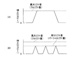
燃料噴射弁30は、燃料噴射弁30のソレノイド34への通電時間の制御によって、或いは、ソレノイド34への供給電流量を調整することによって、ニードルリフト量(即ち、ニードル弁31のリフト量)の最大値が可変に制御されるようになっている。即ち、制御部としてのECU50は、燃焼室20内に燃料を噴射するときの燃料噴射弁30の弁体(ニードル弁32)の(移動量の最大値である)到達リフト量を増減可能である。ニードル弁31を最大リフト量(即ち、フルリフト量)Lmaxまでリフトさせる噴射は、フルリフト噴射と称呼される。一方、ニードル弁31をフルリフト量よりも小さい部分リフト量(即ち、パーシャルリフト量)までの範囲でリフトさせる噴射は、パーシャルリフト噴射と称呼される。図6(A)に、1回のフルリフト噴射のニードルリフト量の時間変化を示す。図6(B)に、3回のパーシャルリフト噴射のニードルリフト量の時間変化を示す。
(Difference between high lift injection and low lift injection)
The
前述したように、燃料噴射弁30によって燃料を噴射する場合、ニードルリフト量Lが「0」から到達リフト量(L1又はL2)まで変化するのに伴って燃料が燃料通路FPからサックS内に流入し、次いで噴孔31aを通して燃料が外部へと噴射される。その後、ニードルリフト量Lがは到達リフト量から「0」まで戻り、サックSと燃料通路FPとが遮断され、燃料の噴射が終了する。この際、ニードルシート壁面32cとノズルシート壁面31cとの間隔は、フルリフト噴射の場合の方が、パーシャルリフト噴射の場合よりも広い。従って、燃料通路FPからサックS内に流入する燃料の流量は、フルリフト噴射の場合の方が、パーシャルリフト噴射の場合よりも大きい。即ち、噴孔31aを通して外部へと噴射される燃料の圧力は、フルリフト噴射の場合の方が、パーシャルリフト噴射の場合よりも高い。その結果、噴孔31aを通して外部へと噴射される燃料の噴霧の運動量(貫徹力)もまた、フルリフト噴射の場合の方が、パーシャルリフト噴射の場合よりも高い。
As described above, when the fuel is injected by the
<第1形態に係る燃料噴射制御>
第1形態の作動について説明する。一般的には、第1形態に係る燃料噴射制御装置は、混合気の空燃比(A/F)が目標空燃比になるように、燃料噴射弁30から噴射される燃料量についてフィードバック制御を行う。前述したように、成層燃焼においては、気筒内全体としては希薄(リーン)な混合気の燃焼により燃料消費率が改善される。具体的には、本制御装置は、混合気の空燃比(A/F)が理論空燃比(14.7)よりも大きい(リーンな)目標空燃比となるように制御を行う。このフィードバック制御においては、触媒より上流の排気経路中に配設された空燃比センサによって得られる空燃比情報と、予め設定された目標空燃比と、の偏差をなくすような制御が行われる。空燃比フィードバック制御の詳細については当業者に周知であるので、本明細書における詳細な説明は割愛する。
<Fuel injection control according to the first embodiment>
The operation of the first form will be described. In general, the fuel injection control device according to the first embodiment performs feedback control on the amount of fuel injected from the
更に、第1形態に係る燃料噴射制御装置は、成層燃焼を実施すべく、制御部としてのECU50により、機関10の圧縮行程において燃料を複数回に分けて噴射する分割噴射(「マルチ噴射」と称される場合もある)を行う。分割噴射とは、1機関サイクルにおいて、比較的短時間の間に燃料噴射弁を複数回開閉することによって、燃料噴射のオンとオフとを連続的に繰り返す噴射である。
Further, in the fuel injection control device according to the first embodiment, split injection (“multi-injection”) in which fuel is divided into a plurality of times in the compression stroke of the
ところで、従来技術に係る燃料噴射制御装置が圧縮行程において分割噴射を行う場合、一般的には、図17に示されているように、分割噴射によって噴射される燃料の総量を複数回の噴射に対して均等に分割することにより、分割噴射における1回の噴射当たりの燃料噴射量が定められる。図17の下側には、このような場合におけるクランク角度(横軸)とピストンの位置(左側の縦軸)との関係を示すグラフ(曲線)と、クランク角度(横軸)と燃料噴射弁のリフト量(右側の縦軸)との関係を示すグラフ(5つのパルス状波形)と、が示されている。 By the way, when the fuel injection control device according to the related art performs divided injection in the compression stroke, generally, as shown in FIG. 17, the total amount of fuel injected by the divided injection is divided into a plurality of injections. On the other hand, by dividing equally, the fuel injection amount per injection in the divided injection is determined. The lower side of FIG. 17 shows a graph (curve) showing the relationship between the crank angle (horizontal axis) and the piston position (left vertical axis) in such a case, the crank angle (horizontal axis), and the fuel injection valve. And a graph (five pulse-like waveforms) showing the relationship with the lift amount (right vertical axis).
上記曲線によって示されているように、クランク角度が−180°から0°へと増大するのに伴って、ピストンの位置が圧縮下死点(BDC)から圧縮上死点(TDC)へと移動している。即ち、クランク角度が−180°から0°に至るまでの期間において、当該機関は圧縮行程にある。一方、クランク角度が0°から180°へと増大するのに伴って、ピストンの位置が圧縮上死点(TDC)から膨張下死点(BDC)へと移動している。即ち、クランク角度が0°から180°に至るまでの期間において、当該機関は膨張行程にある。 As shown by the curve above, as the crank angle increases from -180 ° to 0 °, the piston position moves from compression bottom dead center (BDC) to compression top dead center (TDC). doing. That is, the engine is in the compression stroke during the period from the crank angle of −180 ° to 0 °. On the other hand, as the crank angle increases from 0 ° to 180 °, the position of the piston moves from the compression top dead center (TDC) to the expansion bottom dead center (BDC). That is, the engine is in the expansion stroke during the period from the crank angle from 0 ° to 180 °.
上記5つのパルス状波形によって示されているように、この例においては、機関の圧縮行程において分割噴射によって噴射される燃料の総量を5回に均等に分けて噴射する。具体的には、分割噴射を構成する5回の噴射における燃料噴射弁の到達リフト量を全て同じに設定する。図17の上側には、このような場合におけるクランク角度(横軸)と噴霧の運動量(縦軸)との関係を示すグラフ(5つのパルス状波形)が示されている。上記5つのパルス状波形によって示されているように、この例においては、分割噴射を構成する5回の噴射において燃料噴射弁から噴射される燃料の噴霧の運動量(貫徹力)は全て同じとなる。 As shown by the above five pulse waveforms, in this example, the total amount of fuel injected by split injection in the compression stroke of the engine is equally divided into five times. Specifically, the ultimate lift amounts of the fuel injection valves in the five injections constituting the divided injection are all set to be the same. In the upper side of FIG. 17, a graph (five pulse waveforms) showing the relationship between the crank angle (horizontal axis) and the spray momentum (vertical axis) in such a case is shown. As shown by the above five pulse waveforms, in this example, the momentum (penetration force) of the fuel spray injected from the fuel injection valve in the five injections constituting the divided injection is the same. .
ところで、分割噴射の1回目の噴射の時点(即ち、圧縮行程における最初の噴射)においては、ピストンが燃料噴射弁から遠く離れている。そのため、燃料噴射弁から噴射される燃料の噴霧の運動量(貫徹力)が高い場合、前述したように、燃料の噴霧をピストンキャビティ内に進入させて点火プラグ方向へ偏向させることが難しい場合がある。 Incidentally, at the time of the first injection of the divided injection (that is, the first injection in the compression stroke), the piston is far away from the fuel injection valve. Therefore, when the momentum (penetration force) of the fuel spray injected from the fuel injection valve is high, as described above, it may be difficult to cause the fuel spray to enter the piston cavity and deflect it toward the spark plug. .
具体的には、例えば、サイド噴射方式内燃機関において運動量(貫徹力)が高い燃料噴射を行う場合、圧縮行程噴射の中期においては、図18の(b)によって表されているように、燃料噴射弁から噴射される燃料の噴霧がピストンキャビティ内に適切に導かれ、ピストンキャビティの内壁によって点火プラグ方向へ偏向されて成層燃焼に供される。一方、圧縮行程噴射の初期においては、燃料噴射弁とピストンとの距離が大きいために、その後、上昇してくるピストンの冠面と燃料の噴霧とが衝突するまでに燃料の噴霧が燃焼室内で移動してピストンキャビティから逸れてしまい、ピストンキャビティ内に進入できない場合がある。図18の(a)に示す例においては、噴射直後の燃料の噴霧はピストンキャビティの上部にあるものの、その後ピストンが上昇して、その冠面と燃料の噴霧とが衝突する頃には、黒い矢印によって表されているように、燃料の噴霧はピストンキャビティを飛び越え、向かって右側のシリンダ内壁付近まで到達してしまっている。即ち、燃料の噴霧がピストンキャビティ内に適切に導かれない。その結果、ピストンキャビティによって点火プラグ方向へ偏向されて良好な着火性を有する混合気を点火プラグ近傍に形成する燃料が減少し、結果として成層燃焼が不安定となる虞がある。 Specifically, for example, when fuel injection with a high momentum (penetration force) is performed in a side injection type internal combustion engine, as shown by (b) in FIG. The fuel spray injected from the valve is appropriately guided into the piston cavity, deflected toward the spark plug by the inner wall of the piston cavity, and used for stratified combustion. On the other hand, since the distance between the fuel injection valve and the piston is large at the initial stage of the compression stroke injection, the fuel spray does not reach the combustion chamber until the rising crown of the piston collides with the fuel spray. In some cases, it moves away from the piston cavity and cannot enter the piston cavity. In the example shown in FIG. 18 (a), the fuel spray immediately after injection is in the upper part of the piston cavity, but when the piston rises thereafter and the crown surface collides with the fuel spray, the fuel spray is black. As shown by the arrow, the fuel spray jumps over the piston cavity and reaches the vicinity of the inner wall of the cylinder on the right side. That is, the fuel spray is not properly guided into the piston cavity. As a result, the amount of fuel that is deflected by the piston cavity toward the spark plug and forms an air-fuel mixture having good ignitability in the vicinity of the spark plug is reduced, and as a result, stratified combustion may become unstable.
一方、第1形態に係る燃料噴射制御装置は、ECU50により、機関10の圧縮行程の第1の期間(図7においては約−80°から約−40°までのクランク角度の範囲)において5回の噴射によって燃料を噴射する分割噴射を行う。このとき、個々の噴射における到達リフト量は機関10のクランク角度が圧縮上死点に近くなるほど大きい値に設定される。図17と同様に、図7の下側には、このような場合におけるクランク角度(横軸)とピストンの位置(左側の縦軸)との関係を示すグラフ(曲線)と、クランク角度(横軸)と燃料噴射弁のリフト量(右側の縦軸)との関係を示すグラフ(5つのパルス状波形)と、が示されている。
On the other hand, in the fuel injection control device according to the first embodiment, the
図7の上側には、このような場合におけるクランク角度(横軸)と噴霧の運動量(縦軸)との関係を示すグラフ(5つのパルス状波形)が示されている。上記5つのパルス状波形によって示されているように、この例においては、分割噴射を構成する5回の噴射において燃料噴射弁から噴射される燃料の噴霧の運動量(貫徹力)は、機関10のクランク角度が圧縮上死点に近くなるほど大きくなっている。 On the upper side of FIG. 7, a graph (five pulse waveforms) showing the relationship between the crank angle (horizontal axis) and the spray momentum (vertical axis) in such a case is shown. As shown by the above five pulse waveforms, in this example, the momentum (penetration force) of the fuel spray injected from the fuel injection valve in the five injections constituting the divided injection is The crank angle increases as it approaches the compression top dead center.
上記により、第1形態に係る燃料噴射制御装置においては、燃料噴射弁とピストンとの距離が大きい圧縮行程噴射の初期において燃料噴射弁から噴射される燃料の噴霧の運動量(貫徹力)が小さい。その結果、圧縮行程噴射の初期においても良好な着火性を有する可燃混合気を点火プラグの近傍に形成することができ、安定的な成層燃焼を確保することができる。 As described above, in the fuel injection control device according to the first embodiment, the momentum (penetration force) of the fuel spray injected from the fuel injection valve at the initial stage of the compression stroke injection where the distance between the fuel injection valve and the piston is large is small. As a result, a combustible air-fuel mixture having good ignitability can be formed in the vicinity of the spark plug even in the initial stage of the compression stroke injection, and stable stratified combustion can be ensured.
具体的には、例えば、サイド噴射方式内燃機関の圧縮行程において複数回に分けて燃料を噴射する分割噴射を行う場合、ピストンの位置が低い圧縮行程噴射の初期においては、図8の(a)に示されているように低い運動量(貫徹力)を有する燃料の噴霧が噴射される。その結果、図18の(a)に示した従来技術に係る燃料噴射制御装置におけるように燃料の噴霧がピストンキャビティを飛び越えて燃焼室の右端付近まで到達することが回避される。このように噴射された燃料の噴霧は、その後クランク角度が圧縮上死点に近くなるのに伴って上昇してくるピストンキャビティ内に捉えられ、良好な着火性を有する可燃混合気を点火プラグの近傍に形成する。一方、圧縮行程噴射の中期以降においては、図8の(b)及び(c)によって表されているように、ピストンが燃料噴射弁に近付くほど、燃料噴射弁から噴射される燃料の噴霧の運動量(貫徹力)が徐々に増大される。このように噴射された燃料の噴霧は、ピストンキャビティ内に適切に導かれ、ピストンキャビティの内壁によって点火プラグ方向へ偏向されて成層燃焼に供される。尚、分割噴射の回数及び個々の噴射における燃料の噴射量等の詳細については後述する。 Specifically, for example, in the case of performing split injection in which fuel is injected in a plurality of times in the compression stroke of a side injection type internal combustion engine, in the initial stage of compression stroke injection where the piston position is low, (a) in FIG. A fuel spray having a low momentum (penetration force) is injected as shown in FIG. As a result, it is avoided that the fuel spray jumps over the piston cavity and reaches the vicinity of the right end of the combustion chamber as in the conventional fuel injection control device shown in FIG. The fuel spray thus injected is caught in the piston cavity that rises as the crank angle approaches the compression top dead center, and the combustible air-fuel mixture having good ignitability is removed from the spark plug. Form in the vicinity. On the other hand, after the middle stage of the compression stroke injection, as represented by (b) and (c) in FIG. 8, the momentum of the fuel spray injected from the fuel injection valve the closer the piston is to the fuel injection valve. (Penetration power) is gradually increased. The fuel spray thus injected is appropriately guided into the piston cavity, deflected toward the spark plug by the inner wall of the piston cavity, and used for stratified combustion. Details of the number of divided injections and the amount of fuel injected in each injection will be described later.
(第1形態における燃料噴射制御フロー)
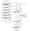
第1形態の作動につき、図9のフローチャートを参照しながら説明する。ECU50のCPUは、所定クランク角度において図9のフローチャートに示されたルーチンを実行するようになっている。従って、適当なタイミングになると、図9の処理が開始され、先ずステップ1101において、クランクポジションセンサ51及びカムポジションセンサ(図示せず)からの信号に基づいてECU50が機関回転速度NE及び絶対クランク角度を検出する。次にステップ1102において、エアフローメータ52からの信号に基づいてECU50が吸入空気量を検出する。そして、ECU50は、ステップ1103において、機関回転速度NE及び吸入空気量等に基づいて燃料噴射量(1サイクル当たりに要求される燃料の噴射量)Qを算出する。前述したように、成層燃焼においては、気筒内全体としては希薄(リーン)な混合気の燃焼が可能となる。従って、ECU50は、混合気の空燃比(A/F)が理論空燃比よりも大きい(リーンな)目標空燃比となる燃料噴射量Qを算出する。
(Fuel injection control flow in the first embodiment)
The operation of the first embodiment will be described with reference to the flowchart of FIG. The CPU of the
次いで、ステップ1104において、ECU50は、例えば、機関回転速度NE及び燃料噴射量Q等に基づいて燃料噴射時期(燃料噴射を実行するクランク角度の範囲)を算出する。尚、前述したように燃料噴射量Qを増大させると燃焼室壁面からの熱によって燃料が可燃混合気となるのに必要な期間が長くなるので、燃料噴射時期は、この期間を確保することが可能であるように定められる。このように決定された燃料噴射時期(クランク角度の範囲)及び機関回転速度NEから、燃料噴射を実行することが許容される期間の時間的長さが特定される。尚、この例においては、上記のように決定された燃料噴射時期の全てに亘って分割噴射が行われ、その間、機関10のクランク角度が圧縮上死点に近くなるほど到達リフト量が増大される。即ち、この例においては、燃料噴射時期は第1の期間と一致する。
Next, at
次に、ステップ1105おいて、ECU50は、このように特定された燃料噴射時期の長さ、燃料噴射弁30の開閉速度(ECU50からの指示信号に対する応答速度)及び1回の噴射によって燃料噴射弁30から噴射することができる燃料の量等に基づいて、圧縮行程の第1の期間における分割噴射の回数(第1期間噴射回数)nを算出する。
Next, in
ここで、ステップ1110において、ECU50は、カウンタiを0(ゼロ)に設定する。次のステップ1120において、ECU50は、カウンタiに1を加えてカウントアップする。更に、ECU50は、次のステップ1135において、i回目の燃料噴射における到達リフト量を算出する。この例においては、1回目の燃料噴射における到達リフト量をhiniとし、その後、2回目以降の燃料噴射においては等量(Δhu)ずつ到達リフト量を増大させる。この場合、i回目の燃料噴射における到達リフト量hiは以下の式(1)によって表される。
Here, in

尚、1回目の燃料噴射における到達リフト量hiniは、例えば、第1の期間における最初の噴射において燃料噴射弁30から噴射される燃料の噴霧がピストンキャビティ60を飛び越えて、向かって右側のシリンダ内壁付近まで到達してしまわない程度の到達リフト量に設定される。2回目以降の燃料噴射における到達リフト量の増分Δhuの具体的な大きさは、例えば、燃料噴射弁30におけるリフト量の制御精度、個々の噴射タイミングにおけるクランク角度(燃料噴射弁30とピストン17との距離)、機関回転速度NE及び燃料噴射量Q等に基づいて設定される。このように設定されたi回目の燃料噴射における到達リフト量hi(i=1,2,3…)は、噴射の実行タイミングと共に、次の燃料噴射実行時に使用される設定値として、次のステップ1160において、例えば、ECU50が備えるデータ記憶装置(例えば、RAM等)に格納される。
Note that the ultimate lift amount hini in the first fuel injection is, for example, that the fuel spray injected from the
次のステップ1170においては、第1の期間においてn回に分割して行われる燃料噴射の全てについて到達リフト量hiが設定されたか否かをECU50が判定する。具体的には、ECU50は、iがnに等しいか否かを判定する。iがnに等しいと判定された場合(ステップ1170:Yes)、ECU50は次のステップ1180に進む。このとき、n回にわたる分割噴射の全てについての到達リフト量hiが既に設定されており、それぞれがデータ記憶装置に格納されている。ステップ1180においては、ステップ1104において算出された燃料噴射時期(第1の期間)、ステップ1105において算出された第1期間噴射回数n及びステップ1135において算出されてステップ1160においてデータ記憶装置に格納された到達リフト量hiに基づいて、燃料噴射の実行が指示される。
In the
一方、ステップ1170においてiがnに等しくないと判定された場合(ステップ1170:No)、ECU50はステップ1120に戻り、ステップ1120からステップ1170までのフローが繰り返される。これにより、n回にわたる分割噴射の全てについての到達リフト量hiが設定されるまで、ステップ1120からステップ1170までのフローが繰り返される。
On the other hand, when it is determined in
ところで、機関10の1サイクルにおいて上記第1期間における分割噴射の他に燃料を噴射する機会が無い場合、当然のことながら、1サイクル当たりに要求される燃料噴射量Qと上記分割噴射全体としての燃料噴射量の総量とが等しくなるように、第1期間噴射回数n及び個々の噴射における到達リフト量hiが設定される。即ち、以下の式(2)が成立するように、第1期間噴射回数n及び個々の噴射における到達リフト量hiが設定される。
By the way, when there is no opportunity to inject fuel in addition to the divided injection in the first period in one cycle of the
上式中、qiは分割噴射を構成する個々の噴射における燃料の噴射量である。例えば、図6の(B)に示したような分割噴射を行う場合、個々の噴射における到達リフト量hiが大きいほど、個々の噴射における燃料の噴射量qiは大きい。このように、個々の噴射における燃料の噴射量qiは個々の噴射における到達リフト量hiと正の相関を有する。上式中、個々の噴射における燃料の噴射量qiは、少なくとも個々の噴射における到達リフト量hiを引数とする関数fによって表されている。 In the above equation, qi is the fuel injection amount in each injection constituting the divided injection. For example, in the case of performing split injection as shown in FIG. 6B, the larger the ultimate lift amount hi in each injection, the larger the fuel injection amount qi in each injection. Thus, the fuel injection amount qi in each injection has a positive correlation with the ultimate lift amount hi in each injection. In the above equation, the fuel injection amount qi in each injection is represented by a function f having at least the ultimate lift amount hi in each injection as an argument.
尚、上記においては機関10の1サイクルにおいて第1期間における分割噴射の他に燃料を噴射する機会が無い場合について説明したが、例えば、第1の期間に行われる分割噴射のみによっては1サイクル当たりに要求される燃料噴射量Qを噴射することが困難である場合等においては、第1の期間より前及び/又は後に更なる燃料噴射を行ってもよい。
In the above description, the case where there is no opportunity to inject fuel in addition to the divided injection in the first period in one cycle of the
更に、上記フローチャートによって表される燃料噴射制御フローを構成する各ルーチンの実行順序は、矛盾を生じない範囲で入れ替えてもよい。更に、上記説明においては2回目以降の燃料噴射において到達リフト量を等量(Δhu)ずつ増大させたが、2回目以降の燃料噴射における到達リフト量の増分(Δhu)は必ずしも等しい必要は無く、その都度異なっていてもよい。 Furthermore, the execution order of the routines constituting the fuel injection control flow represented by the flowchart may be changed within a range where no contradiction occurs. Furthermore, in the above description, the ultimate lift amount is increased by equal amount (Δhu) in the second and subsequent fuel injections, but the increment (Δhu) of the ultimate lift amount in the second and subsequent fuel injections is not necessarily equal. It may be different each time.
以上のように、第1形態に係る燃料噴射制御装置によれば、第1の期間に行われる分割噴射を構成する個々の噴射における到達リフト量hiが機関10のクランク角度が圧縮上死点に近くなるほど大きい値に設定される。従って、燃料噴射弁とピストンとの距離が大きい圧縮行程噴射の初期の噴射においては、到達リフト量が小さい値に設定される。即ち、圧縮行程噴射の初期の噴射においては、燃料噴射弁から噴射される燃料の噴霧の運動量(貫徹力)が小さい。その結果、圧縮行程噴射の初期において噴射された燃料のうち成層燃焼に供される燃料の減少を回避することができる。更に、圧縮行程噴射の中期から後期にかけては、適度な運動量(貫徹力)を有する燃料の噴霧がピストンキャビティ内に適切に導かれ、点火プラグ方向へ偏向されて成層燃焼に供される。その結果、良好な着火性を有する可燃混合気を点火プラグ近傍に形成することができ、安定的な成層燃焼を確保することができる。
As described above, according to the fuel injection control apparatus according to the first embodiment, the ultimate lift amount hi in each injection constituting the divided injection performed in the first period is the compression top dead center of the crank angle of the
<第2実施形態>
ところで、前述したように、例えば、第1の期間に行われる分割噴射のみによっては1サイクル当たりに要求される燃料噴射量Qを噴射することが困難である場合等においては、上記第1の期間より前にも燃料を噴射してもよい。この噴射における到達リフト量は、第1の期間における最初の噴射を行うための到達リフト量よりも大きい値に設定することも、小さい値に設定することも、或いは第1の期間における最初の噴射を行うための到達リフト量と同じ値に設定することもできる。
Second Embodiment
By the way, as described above, for example, when it is difficult to inject the fuel injection amount Q required per cycle only by the divided injection performed in the first period, the first period Fuel may be injected before that. The ultimate lift amount in this injection may be set to a value larger or smaller than the ultimate lift amount for performing the first injection in the first period, or the first injection in the first period. It is also possible to set it to the same value as the amount of lift for performing.
しかしながら、機関の圧縮行程における第1の期間よりも前においては、第1の期間における最初の噴射を行うときよりも、燃料噴射弁とピストンとの距離が更に大きい。従って、前述したように燃料の噴霧がピストンキャビティから逸れることを回避するためには、機関の圧縮行程における第1の期間よりも前に行われる噴射における到達リフト量を、第1の期間における最初の噴射を行うための到達リフト量よりも小さい値に設定することが望ましい。 However, before the first period in the compression stroke of the engine, the distance between the fuel injection valve and the piston is greater than when performing the first injection in the first period. Therefore, as described above, in order to avoid the fuel spray from deviating from the piston cavity, the ultimate lift amount in the injection performed before the first period in the compression stroke of the engine is set to the initial lift amount in the first period. It is desirable to set a value smaller than the ultimate lift amount for performing the injection.
そこで、本発明の第2実施形態(以降、「第2形態」と称される場合がある)の制御部は、
前記第1の期間より前の第2の期間において前記燃料噴射弁に燃料を1回以上噴射させると共に同第2の期間における各噴射に対する到達リフト量を前記第1の期間における最初の噴射に対する到達リフト量よりも小さい値に設定する。
Therefore, the control unit of the second embodiment of the present invention (hereinafter sometimes referred to as “second form”)
In the second period before the first period, the fuel injection valve is made to inject fuel one or more times, and the ultimate lift amount for each injection in the second period is reached with respect to the first injection in the first period. Set a value smaller than the lift amount.
これによれば、前述したように、第1の期間より前の第2の期間において噴射される燃料は相当に小さい運動量を有するので、その少なくとも一部(望ましくは多く)が燃料噴射弁の近傍(燃焼室の上部)に滞留し易くなる。従って、第2の期間において噴射された燃料は、後にピストンが上昇したときにピストンキャビティ内に捕捉され易く、良好な着火性を有する可燃混合気の形成に貢献し易い。その結果、より多くの燃料を用いて可燃混合気を形成することが可能となる。 According to this, as described above, since the fuel injected in the second period before the first period has a considerably small momentum, at least a part (preferably much) of the fuel is in the vicinity of the fuel injection valve. It tends to stay in (the upper part of the combustion chamber). Therefore, the fuel injected in the second period is likely to be trapped in the piston cavity when the piston later rises, and contributes to the formation of a combustible mixture having good ignitability. As a result, a combustible air-fuel mixture can be formed using more fuel.
この場合、第1の期間及び第2の期間における分割噴射の他に燃料を噴射する機会が無い場合は、1サイクル当たりに要求される燃料噴射量Qと第1の期間及び第2の期間における分割噴射の全体としての燃料噴射量の総量とが等しくなるように、第1期間噴射回数n及び第2期間における噴射回数、個々の噴射における到達リフト量hiが設定される。 In this case, if there is no opportunity to inject fuel in addition to the divided injection in the first period and the second period, the fuel injection amount Q required per cycle and the first period and the second period The first number of injections n, the number of injections in the second period, and the ultimate lift amount hi for each injection are set so that the total amount of fuel injections as a whole of the divided injections becomes equal.
<第3実施形態>
ところで、前述したように、例えば、第1の期間に行われる分割噴射のみによっては1サイクル当たりに要求される燃料噴射量Qを噴射することが困難である場合等においては、上記第1の期間より後にも燃料を噴射してもよい。この噴射における到達リフト量は、第1の期間における最後の噴射を行うための到達リフト量よりも大きい値に設定することも、小さい値に設定することも、或いは第1の期間における最後の噴射を行うための到達リフト量と同じ値に設定することもできる。
<Third Embodiment>
By the way, as described above, for example, when it is difficult to inject the fuel injection amount Q required per cycle only by the divided injection performed in the first period, the first period Fuel may be injected later. The ultimate lift amount in this injection may be set to a value larger or smaller than the ultimate lift amount for performing the final injection in the first period, or the final injection in the first period. It is also possible to set it to the same value as the amount of lift for performing.
しかしながら、機関の圧縮行程においてはクランク角度が圧縮上死点に近くなるほどピストンが燃料噴射弁に近付く。従って、圧縮行程の末期に近付くほどピストンと燃料噴射弁との距離が小さくなる。それにも拘わらず、クランク角度が圧縮上死点に近くなるほど燃料噴射弁から噴射される燃料の噴霧の運動量(貫徹力)を増大させ続けると、ピストンと燃料噴射弁との距離に対して燃料の噴霧の運動量(貫徹力)が過大となり、燃料ウェットが発生する虞がある。燃料ウェットが発生すると、例えばスモーク及びPM等が発生する虞がある。 However, in the compression stroke of the engine, the piston approaches the fuel injection valve as the crank angle approaches the compression top dead center. Accordingly, the closer the end of the compression stroke is, the smaller the distance between the piston and the fuel injection valve is. Nevertheless, if the momentum (penetration force) of the fuel spray injected from the fuel injection valve continues to increase as the crank angle approaches the compression top dead center, the amount of fuel relative to the distance between the piston and the fuel injection valve will increase. The momentum of spraying (penetration force) becomes excessive, and there is a risk of fuel wetness. When fuel wet occurs, for example, smoke and PM may be generated.
ここで、上記につき、図10を参照しながら説明する。図10は、前述したように、圧縮行程において燃料の運動量(貫徹力)を増大させ続けた場合における初期(a)、中期1(b)、中期2(c)及び後期(d)における燃料の噴霧及びピストンの位置の状況を示す模式図である。第1形態に係る燃料噴射制御装置について図8を参照しながら説明したように、(a)初期から(c)中期2まではピストンの位置に対して適切な燃料の噴霧が形成されている。しかしながら、ピストンと燃料噴射弁との距離が更に小さくなる(d)後期においても燃料の運動量(貫徹力)を更に増大させると、ウェット量が増大する。 Here, the above will be described with reference to FIG. As described above, FIG. 10 shows the fuel in the initial stage (a), the intermediate period 1 (b), the intermediate period 2 (c), and the late period (d) when the momentum (penetration force) of the fuel is continuously increased in the compression stroke. It is a schematic diagram which shows the condition of the position of spray and a piston. As described with reference to FIG. 8 for the fuel injection control apparatus according to the first embodiment, an appropriate fuel spray is formed with respect to the position of the piston from (a) the initial stage to (c) the middle stage 2. However, when the distance between the piston and the fuel injection valve is further decreased (d) and the momentum (penetration force) of the fuel is further increased even in the latter period, the wet amount increases.
従って、圧縮行程の後期におけるウェット量の増大を防止するためには、ピストンと燃料噴射弁との距離が極めて小さくなる圧縮行程の後期において燃料噴射弁の到達リフト量を増大させないことが望ましい。より具体的には、本発明に係る燃料噴射制御装置が備える制御部は、圧縮行程の第1期間より後は、到達リフト量を予め定められた所定の値に維持するように燃料噴射弁を制御することが望ましい。 Therefore, in order to prevent an increase in the wet amount in the second half of the compression stroke, it is desirable not to increase the ultimate lift amount of the fuel injection valve in the second half of the compression stroke where the distance between the piston and the fuel injection valve becomes extremely small. More specifically, the control unit provided in the fuel injection control device according to the present invention controls the fuel injection valve so as to maintain the ultimate lift amount at a predetermined value after the first period of the compression stroke. It is desirable to control.
そこで、本発明の第3実施形態(以降、「第3形態」と称される場合がある)の制御部は、
前記第1の期間より後の第3の期間において前記燃料噴射弁に燃料を1回以上噴射させると共に同第3の期間における各噴射に対する到達リフトを予め定められた所定の値に維持する。
Therefore, the control unit of the third embodiment of the present invention (hereinafter sometimes referred to as “third form”)
In a third period after the first period, fuel is injected into the fuel injection valve one or more times, and the ultimate lift for each injection in the third period is maintained at a predetermined value.
上記「予め定められた所定の値」は、圧縮行程における第1の期間より後の第3の期間においてウェット量の増大を伴わずに燃料噴射を行うことができる到達リフト量の上限値に対応する値である。換言すれば、上記「予め定められた所定の値」は、第3の期間に行われる燃料噴射において、それよりも高い値に到達リフト量を設定するとウェット量が増大する閾値に対応する値であり、例えば事前実験等によって予め定めることができる。 The above-mentioned “predetermined predetermined value” corresponds to the upper limit value of the ultimate lift amount at which fuel injection can be performed without increasing the wet amount in the third period after the first period in the compression stroke. The value to be In other words, the “predetermined predetermined value” is a value corresponding to a threshold value that increases the wet amount when the ultimate lift amount is set to a higher value in the fuel injection performed in the third period. Yes, for example, it can be determined in advance by a prior experiment or the like.
厳密には、分割噴射を構成する個々の噴射において燃料ウェットが発生するか否かは、個々の噴射における燃料噴射弁の到達リフト量のみならず、個々の噴射タイミングにおけるクランク角度(燃料噴射弁とピストンとの距離)及び機関回転速度NE等にも影響される。従って、上記「予め定められた所定の値」は、例えば、種々の機関回転速度NEにおいて種々の噴射タイミング(クランク角度)及び到達リフト量にて燃料を噴射する事前実験等によって予め定めることができる。 Strictly speaking, whether or not fuel wet occurs in each injection constituting the divided injection is determined not only by the amount of lift reached by the fuel injection valve in each injection, but also by the crank angle at each injection timing (with the fuel injection valve). It is also affected by the distance to the piston) and the engine speed NE. Therefore, the “predetermined predetermined value” can be determined in advance by, for example, preliminary experiments for injecting fuel at various engine rotational speeds NE at various injection timings (crank angles) and ultimate lift amounts. .
第3形態に係る燃料噴射制御装置においては、第1の期間より後の第3の期間において、上記のように定められる「予め定められた所定の値」に到達リフトが維持される。これにより、燃料噴射弁とピストンとの距離が小さい圧縮行程噴射の後期において燃料の噴霧の運動量(貫徹力)が過大となることが回避される。その結果、ウェット量の増大が防止され、例えばスモーク及びPM等の問題の発生が低減される。 In the fuel injection control device according to the third mode, the ultimate lift is maintained at the “predetermined predetermined value” determined as described above in the third period after the first period. Thereby, it is avoided that the momentum (penetration force) of the fuel spray becomes excessive in the latter stage of the compression stroke injection in which the distance between the fuel injection valve and the piston is small. As a result, an increase in the wet amount is prevented, and the occurrence of problems such as smoke and PM is reduced.
尚、第3形態における内燃機関、制御部及び燃料噴射弁の構成等については第1形態と共通であるので、ここでは重複する説明は繰り返さない。 Note that the configuration of the internal combustion engine, the control unit, and the fuel injection valve in the third embodiment is the same as that in the first embodiment, and therefore, repeated description will not be repeated here.
<第3形態に係る燃料噴射制御>
ここで、第3形態の作動について説明する。図11の下側には、図7と同様に、このような場合におけるクランク角度(横軸)とピストンの位置(左側の縦軸)との関係を示すグラフ(曲線)と、クランク角度(横軸)と燃料噴射弁のリフト量(右側の縦軸)との関係を示すグラフ(6つのパルス状波形)と、が示されている。図11の下側に示されているように、第3形態に係る燃料噴射制御装置も、ECU50により、機関10の圧縮行程の第1の期間(図11においては約−80°から約−50°までのクランク角度の範囲)において4回の噴射によって燃料を噴射する分割噴射を行う。このとき、個々の噴射における到達リフト量を機関10のクランク角度が圧縮上死点に近くなるほど大きい値に設定する。
<Fuel injection control according to the third embodiment>
Here, the operation of the third embodiment will be described. 11, the graph (curve) showing the relationship between the crank angle (horizontal axis) and the position of the piston (vertical axis on the left side) and the crank angle (horizontal axis) are as shown in FIG. A graph (six pulse-like waveforms) showing the relationship between the axis) and the lift amount of the fuel injection valve (right vertical axis) is shown. 11, the fuel injection control apparatus according to the third embodiment is also controlled by the
上記のように、第3形態に係る燃料噴射制御装置は、第1の期間における噴射に該当する1回目から4回目の噴射までは到達リフト量を増大させるものの、第1の期間より後の第3の期間(図11においては約−40°から約−30°までのクランク角度の範囲)における噴射(5回目以降の噴射)においては、4回目の噴射における到達リフト量に到達リフト量を一定に維持する。即ち、この例においては、上述した「予め定められた所定の値」は「4回目の噴射における到達リフト量」(即ち、第1の期間における最後の噴射に対する到達リフト量)と同じ値である。 As described above, the fuel injection control device according to the third embodiment increases the ultimate lift amount from the first injection corresponding to the injection in the first period to the fourth injection, but the second lift after the first period. In the injection in the period 3 (the crank angle range from about −40 ° to about −30 ° in FIG. 11) (the fifth and subsequent injections), the ultimate lift amount is constant to the ultimate lift amount in the fourth injection. To maintain. That is, in this example, the above-mentioned “predetermined predetermined value” is the same value as “the ultimate lift amount in the fourth injection” (that is, the ultimate lift amount in the first period). .
図11の上側には、上記のような場合におけるクランク角度(横軸)と噴霧の運動量(縦軸)との関係を示すグラフ(6つのパルス状波形)が示されている。上記6つのパルス状波形によって示されているように、この例においては、分割噴射を構成する6回の噴射のうち、第1の期間における噴射に該当する1回目から4回目までの噴射においては機関10のクランク角度が圧縮上死点に近くなるほど燃料の噴霧の運動量(貫徹力)が大きくなる。更に、第1の期間より後の第3の期間における噴射(5回目以降の噴射)による燃料の噴霧の運動量(貫徹力)は4回目の噴射における運動量(貫徹力)にて一定に維持される。
On the upper side of FIG. 11, a graph (six pulse waveforms) showing the relationship between the crank angle (horizontal axis) and the momentum of spraying (vertical axis) in the above case is shown. As shown by the above six pulse waveforms, in this example, among the six injections constituting the divided injection, in the first to fourth injections corresponding to the injection in the first period, The closer the crank angle of the
上記により、第3形態に係る燃料噴射制御装置においては、燃料噴射弁とピストンとの距離が大きい圧縮行程噴射の初期において、燃料噴射弁から噴射される燃料の噴霧の運動量(貫徹力)が小さい。その結果、例えば、サイド噴射方式内燃機関において分割噴射を行う場合、ピストンの位置が低い圧縮行程噴射の初期においては、図12の(a)に示されているように低い運動量(貫徹力)を有する燃料の噴霧が噴射される。その結果、図18の(a)に示した従来技術に係る燃料噴射制御装置におけるように燃料の噴霧がピストンキャビティを飛び越えて燃焼室の右端付近まで到達することが回避される。このように噴射された燃料の噴霧は、その運動量(貫徹力)が小さく、その後クランク角度が圧縮上死点に近くなるのに伴って上昇してくるピストンキャビティ内に捉えられ、良好な着火性を有する可燃混合気を点火プラグ近傍に形成する。 As described above, in the fuel injection control device according to the third embodiment, the momentum (penetration force) of the spray of fuel injected from the fuel injection valve is small at the initial stage of the compression stroke injection where the distance between the fuel injection valve and the piston is large. . As a result, for example, when split injection is performed in a side injection type internal combustion engine, a low momentum (penetration force) is obtained as shown in FIG. A fuel spray is injected. As a result, it is avoided that the fuel spray jumps over the piston cavity and reaches the vicinity of the right end of the combustion chamber as in the conventional fuel injection control device shown in FIG. The spray of fuel injected in this way has a small momentum (penetration force), and is then caught in the piston cavity that rises as the crank angle approaches compression top dead center, providing good ignitability. Is formed in the vicinity of the spark plug.
次に、圧縮行程噴射の中期に入ると(中期1及び中期2)、図12の(b)及び(c)によって表されているように、ピストンが燃料噴射弁に近付くほど、燃料噴射弁から噴射される燃料の噴霧の運動量(貫徹力)が徐々に増大される。このように噴射された燃料の噴霧は、ピストンキャビティ内に適切に導かれ、ピストンキャビティの内壁によって点火プラグ方向へ偏向されて成層燃焼に供される。 Next, when the middle stage of the compression stroke injection is entered (mid-term 1 and mid-term 2), as indicated by (b) and (c) in FIG. 12, the closer the piston is to the fuel injection valve, The momentum (penetration force) of the spray of the injected fuel is gradually increased. The fuel spray thus injected is appropriately guided into the piston cavity, deflected toward the spark plug by the inner wall of the piston cavity, and used for stratified combustion.
更に、圧縮行程噴射の後期に入ると、図12の(d)によって表されているように、ピストンが燃料噴射弁に更に近付いても、燃料噴射弁から噴射される燃料の噴霧の運動量(貫徹力)は増大されない。その結果、図10の(d)に示したようなウェット量の増大が防止される。このように噴射された燃料の噴霧は、ピストンキャビティ内に適切に導かれ、ピストンキャビティの内壁によって点火プラグ方向へ偏向されて成層燃焼に供される。 Further, at the later stage of the compression stroke injection, as represented by (d) in FIG. 12, even if the piston is closer to the fuel injection valve, the momentum of fuel spray injected from the fuel injection valve (through) Force) is not increased. As a result, an increase in wet amount as shown in FIG. 10D is prevented. The fuel spray thus injected is appropriately guided into the piston cavity, deflected toward the spark plug by the inner wall of the piston cavity, and used for stratified combustion.
以上のように、第3形態に係る燃料噴射制御装置によれば、圧縮行程噴射の初期においても良好な着火性を有する可燃混合気を点火プラグ近傍に形成し且つ圧縮行程噴射の後期におけるウェット量の増大を防止することにより、安定的な成層燃焼を確保すると共に例えばスモーク及びPM等の問題を回避することができる。 As described above, according to the fuel injection control apparatus according to the third embodiment, the combustible air-fuel mixture having good ignitability even in the initial stage of the compression stroke injection is formed in the vicinity of the spark plug, and the wet amount in the latter stage of the compression stroke injection. By preventing this increase, stable stratified combustion can be ensured and problems such as smoke and PM can be avoided.
(第3形態における燃料噴射制御フロー)
第3形態の作動につき、図13のフローチャートを参照しながら説明する。ECU50のCPUは、所定クランク角度において図13のフローチャートに示されたルーチンを実行するようになっている。尚、図13のフローチャートによって表される第3形態における燃料噴射制御フローは、以下の3点においてのみ、図9のフローチャートによって表される第1形態における燃料噴射制御フローと異なる。
(Fuel injection control flow in the third embodiment)
The operation of the third embodiment will be described with reference to the flowchart of FIG. The CPU of the
1点目は、ステップ1506において、第1の期間より後の第3の期間における分割噴射の回数(第3期間噴射回数)mが算出される点である。2点目は、ステップ1530において圧縮行程におけるi回目の噴射が「第1の期間におけるn回の噴射」に該当するか否かが判定され、i回目の噴射が第1の期間におけるn回の噴射に該当しない場合はステップ1545において到達リフト量が一定に維持される点である。
The first point is that in
3点目は、ステップ1575において、第1の期間及び第3の期間に行われる(n+m回の)燃料噴射の全てについて到達リフト量hiが設定されたか否かをECU50が判定する点である。尚、各ステップに割り振られた番号の下2桁は当該ステップにおいて実行されるルーチンの内容に対応している。即ち、図13と図9とにおいて、下2桁が同じ番号が割り振られたステップにおいては、同じルーチンが実行される。
The third point is that in
従って、図9のフローチャートと同様に、図13のフローチャートにおいても、ステップ1501から1505において、機関回転速度NEの検出、吸入空気量の検出、燃料噴射量Qの算出、燃料噴射時期の算出及び第1期間噴射回数nの算出がそれぞれ実行される。次に、ステップ1506において第3期間噴射回数mが算出される。上述したように、「第3期間噴射回数m」は、第1の期間より後の期間である「第3の期間」における分割噴射の回数である。尚、この例においては、上記のように決定された燃料噴射時期の全てに亘って分割噴射が行われる。そのうち、第1の期間におけるn回の噴射については機関10のクランク角度が圧縮上死点に近くなるほど到達リフト量が増大され、第3の期間におけるm回の噴射については機関10のクランク角度にかかわらず到達リフト量が一定に維持される。即ち、この例においては、燃料噴射時期は第1の期間と第3の期間との合計に一致する。
Therefore, similarly to the flowchart of FIG. 9, in the flowchart of FIG. 13, in
次に、図9のフローチャートと同様に、図13のフローチャートにおいても、ステップ1510においてカウンタiが0(ゼロ)に設定され、次のステップ1520においてカウンタiがカウントアップされる。次に、ステップ1530において圧縮行程におけるi回目の噴射が「第1の期間におけるn回の噴射」に該当するか否かが判定される。ステップ1530においてi回目の噴射が「第1の期間におけるn回の噴射」に該当すると判定された場合(ステップ1530:Yes)、次のステップ1535において、i回目の燃料噴射における到達リフト量が算出される。この際、1回目の燃料噴射における到達リフト量をhiniとし、その後、2回目からn回目までの燃料噴射においては等量(Δhu)ずつ到達リフト量を増大させる。この場合、i回目の燃料噴射における到達リフト量hiは、前述した式(1)によって表される。
Next, similarly to the flowchart of FIG. 9, also in the flowchart of FIG. 13, the counter i is set to 0 (zero) in
尚、1回目の燃料噴射における到達リフト量hini及び2回目からn回目までの燃料噴射における到達リフト量の増分Δhuは前述したように設定される。このように設定された1回目からn回目までの燃料噴射における到達リフト量hi(i=1,2,3…,n)は、次の燃料噴射実行時に使用される設定値として、次のステップ1560において、例えば、ECU50が備えるデータ記憶装置(例えば、RAM等)に格納される。
The ultimate lift amount hini in the first fuel injection and the increment Δhu of the ultimate lift amount in the second to nth fuel injections are set as described above. The reached lift amount hi (i = 1, 2, 3,..., N) in the first to n-th fuel injections set in this way is set as a set value used when the next fuel injection is executed, and the next step. In 1560, for example, the data is stored in a data storage device (for example, a RAM) provided in the
一方、ステップ1530においてi回目の噴射が「第1の期間におけるn回の噴射」に該当しないと判定された場合(ステップ1530:No)、次のステップ1545において、i回目(n+1回目以降)の燃料噴射における到達リフト量が算出される。この例においては、n+1回目以降の燃料噴射における到達リフト量は、n回目の燃料噴射における到達リフト量にて一定に維持される。この場合、i回目の燃料噴射における到達リフト量hiは以下の式(3)によって表される。
On the other hand, when it is determined in
上記のように、n+1回目以降の燃料噴射における到達リフト量hiは、n回目の燃料噴射における到達リフト量hiと同じ値に設定される。このように設定されたn+1回目以降の燃料噴射における到達リフト量hi(i=n+1,n+2…,n+m)は、次の燃料噴射実行時に使用される設定値として、次のステップ1560において、例えば、ECU50が備えるデータ記憶装置(例えば、RAM等)に格納される。
As described above, the reached lift amount hi in the (n + 1) th and subsequent fuel injections is set to the same value as the reached lift amount hi in the nth fuel injection. The reached lift amount hi (i = n + 1, n + 2,..., N + m) in the n + 1 and subsequent fuel injections set in this way is set as a set value used when the next fuel injection is executed, for example, in the
次のステップ1575においては、第1の期間及び第3の期間に行われるn+m回の燃料噴射の全てについて到達リフト量hiが設定されたか否かをECU50が判定する。具体的には、ECU50は、iがn+mに等しいか否かを判定する。iがn+mに等しいと判定された場合(ステップ1575:Yes)、ECU50は次のステップ1580に進む。このとき、n+m回にわたる分割噴射の全てについての到達リフト量hiが既に設定されており、それぞれがデータ記憶装置に格納されている。ステップ1580においては、ステップ1504において算出された燃料噴射時期(第1の期間及び第3の期間)、ステップ1505において算出された第1期間噴射回数n、ステップ1506において算出された第3期間噴射回数m、並びにステップ1535及びステップ1545において算出されてステップ1560においてデータ記憶装置に格納された到達リフト量hiに基づいて、燃料噴射の実行が指示される。
In the
一方、ステップ1575においてiがn+mに等しくないと判定された場合(ステップ1575:No)、ECU50はステップ1520に戻り、ステップ1520からステップ1575までのフローが繰り返される。これにより、n+m回にわたる分割噴射の全てについての到達リフト量hiが設定されるまで、ステップ1520からステップ1575までのフローが繰り返される。
On the other hand, when it is determined in
ところで、機関10の1サイクルにおいて上記第1期間及び第3の期間における分割噴射の他に燃料を噴射する機会が無い場合、当然のことながら、1サイクル当たりに要求される燃料噴射量Qと上記分割噴射全体としての燃料噴射量の総量とが等しくなるように、第1期間噴射回数n、第3期間噴射回数m及び個々の噴射における到達リフト量hiが設定される。即ち、以下の式(2′)が成立するように、第1期間噴射回数n、第3期間噴射回数m及び個々の噴射における到達リフト量hiが設定される。尚、式(2′)におけるqi及び関数fの定義は式(2)と同様である。
By the way, when there is no opportunity to inject fuel in addition to the divided injection in the first period and the third period in one cycle of the
尚、上記においては機関10の1サイクルにおいて第1期間及び第3の期間における分割噴射の他に燃料を噴射する機会が無い場合について説明した。しかしながら、例えば、第1の期間及び第3の期間に行われる分割噴射のみによっては1サイクル当たりに要求される燃料噴射量Qを噴射することが困難である場合等においては、第1の期間及び第3の期間以外の期間に更なる燃料噴射を行ってもよい。例えば、前述したように、第1の期間より前の第2の期間において更なる燃料噴射を行ってもよい。
In the above description, the case where there is no opportunity to inject fuel in addition to the divided injection in the first period and the third period in one cycle of the
更に、上記フローチャートによって表される燃料噴射制御フローを構成する各ルーチンの実行順序は、矛盾を生じない範囲で入れ替えてもよい。更に、上記説明においては2回目からn回目までの燃料噴射において到達リフト量を等量(Δhu)ずつ増大させたが、2回目からn回目までの燃料噴射における到達リフト量の増分(Δhu)は必ずしも等しい必要は無く、その都度異なっていてもよい。 Furthermore, the execution order of the routines constituting the fuel injection control flow represented by the flowchart may be changed within a range where no contradiction occurs. Further, in the above description, the reached lift amount is increased by an equal amount (Δhu) in the second to nth fuel injections, but the increment (Δhu) of the reached lift amount in the second to nth fuel injections is increased. They are not necessarily equal and may be different each time.
加えて、上記説明においてはn+1回目以降の燃料噴射についてステップ1520、1530、1545、1560及び1575のルーチンが繰り返された。しかしながら、上述した例においては、n+1回目以降の燃料噴射における到達リフト量は増大されず、n回目の燃料噴射における到達リフト量と同じに維持される。このようにn+1回目以降の燃料噴射における到達リフト量が一定に維持される場合は、噴射回数がn+1回目に達したら、その後の噴射における到達リフト量をn回目の燃料噴射における到達リフト量に一括して設定してデータ記憶装置に格納し、ステップ1580に進んで燃料噴射の実行を指示してもよい。
In addition, in the above description, the routines of
以上のように、第3形態に係る燃料噴射制御装置によれば、第1の期間に行われる分割噴射を構成する個々の噴射における到達リフト量hiが機関10のクランク角度が圧縮上死点に近くなるほど大きい値に設定される。従って、燃料噴射弁とピストンとの距離が大きい圧縮行程噴射の初期の噴射においては、到達リフト量が小さい値に設定される。即ち、圧縮行程噴射の初期の噴射においては、燃料噴射弁から噴射される燃料の噴霧の運動量(貫徹力)が小さい。その結果、圧縮行程噴射の初期において噴射される燃料のうち成層燃焼に供される燃料の量の減少を回避することができる。更に、圧縮行程噴射の中期においては、適度な運動量(貫徹力)を有する燃料の噴霧がピストンキャビティ内に適切に導かれ、点火プラグ方向へ偏向されて成層燃焼に供される。加えて、圧縮行程噴射の後期においては、燃料の噴霧の運動量(貫徹力)が一定に維持されるのでウェット量の増大が防止される。その結果、良好な着火性を有する可燃混合気を点火プラグ近傍に形成することができ、安定的な成層燃焼を確保すると共に、スモーク及びPM等の問題を回避することができる。
As described above, according to the fuel injection control device according to the third embodiment, the ultimate lift amount hi in each injection constituting the divided injection performed in the first period is the compression top dead center of the crank angle of the
<第4実施形態>
ところで、上述した例においては、第1の期間に行われる分割噴射においては到達リフト量が増大され、その後、第3の期間に行われる分割噴射においては到達リフト量が一定に維持された。即ち、圧縮行程噴射の末期における燃料の噴霧の運動量(貫徹力)は相対的に高い。一方、圧縮行程の末期においては燃料噴射弁とピストンとの距離が極めて小さいので、上述した燃料ウェットに起因する問題が発生する虞が高い。
<Fourth embodiment>
In the above-described example, the ultimate lift amount is increased in the divided injection performed in the first period, and thereafter, the ultimate lift amount is maintained constant in the divided injection performed in the third period. That is, the momentum (penetration force) of the fuel spray at the end of the compression stroke injection is relatively high. On the other hand, since the distance between the fuel injection valve and the piston is extremely small at the end of the compression stroke, there is a high possibility that the problems caused by the above-described fuel wet will occur.
かかる問題を回避するためには、例えば、第1の期間(圧縮行程噴射の初期)における到達リフト量の増大幅を小さくして、圧縮行程噴射の後期における到達リフト量を小さい値に設定し、燃料の噴霧の運動量(貫徹力)を小さくすることが考えられる。或いは、例えば、圧縮上死点の近傍でのクランク角度においては燃料の噴射を禁止する等して、圧縮行程噴射の終了時期を早めることも考えられる。しかしながら、これらの対策によれば、圧縮行程噴射によって噴射され得る燃料の総量が減少するため、機関の運転に必要とされる量の燃料を噴射することが困難となる虞が高まる。 In order to avoid such a problem, for example, the increase amount of the ultimate lift amount in the first period (the initial stage of the compression stroke injection) is reduced, and the ultimate lift amount in the latter stage of the compression stroke injection is set to a small value. It is conceivable to reduce the momentum (penetration force) of fuel spray. Alternatively, for example, it is conceivable to advance the end timing of the compression stroke injection by prohibiting fuel injection at a crank angle near the compression top dead center. However, according to these measures, since the total amount of fuel that can be injected by the compression stroke injection is reduced, there is an increased possibility that it will be difficult to inject the amount of fuel required for engine operation.
そこで、本発明者は、第3の期間において到達リフト量を徐々に減少させることにより、上記問題を回避することができるとの考えに到った。より具体的には、燃料噴射弁とピストンとの距離が大きい第1の期間(圧縮行程噴射の初期)の噴射においては燃料噴射弁の到達リフト量を小さい値から徐々に増大させ、燃料噴射弁とピストンとの距離が大きい第3の期間(圧縮行程噴射の後期)の噴射においては到達リフト量を徐々に減少させる。これにより、圧縮行程噴射の初期の噴射においては燃料の噴霧の運動量(貫徹力)を小さくし、その後の噴射においては燃料の噴霧の運動量(貫徹力)を十分に増大させ、圧縮行程噴射の後期においては燃料の噴霧の運動量(貫徹力)を十分に減少させることができる。 Therefore, the present inventor has come up with the idea that the above problem can be avoided by gradually reducing the amount of lift reached in the third period. More specifically, in the first period (initial stage of compression stroke injection) in which the distance between the fuel injection valve and the piston is large, the ultimate lift amount of the fuel injection valve is gradually increased from a small value, and the fuel injection valve In the third period (the latter stage of the compression stroke injection) in which the distance between the piston and the piston is large, the ultimate lift is gradually decreased. Thus, the momentum (penetration force) of the fuel spray is reduced in the initial injection of the compression stroke injection, and the momentum (penetration force) of the fuel spray is sufficiently increased in the subsequent injection, so that the latter stage of the compression stroke injection. In this case, the momentum (penetration force) of the fuel spray can be sufficiently reduced.
そこで、本発明の第4実施形態(以降、「第4形態」と称される場合がある)の制御部は、
前記第1の期間より後の第3の期間において前記燃料噴射弁に燃料を1回以上噴射させると共に同第3の期間における各噴射に対する到達リフト量を前記内燃機関のクランク角度が圧縮上死点に近くなるほど小さい値に設定する。
Therefore, the control unit of the fourth embodiment of the present invention (hereinafter sometimes referred to as “fourth embodiment”)
In a third period after the first period, fuel is injected into the fuel injection valve at least once, and the ultimate lift amount for each injection in the third period is determined by the crank angle of the internal combustion engine being a compression top dead center Set to a smaller value as it approaches.
厳密には、分割噴射を構成する個々の噴射において燃料ウェットが発生するか否かは、前述したように、個々の噴射における燃料噴射弁の到達リフト量のみならず、個々の噴射タイミングにおけるクランク角度(燃料噴射弁とピストンとの距離)及び機関回転速度NE等にも影響される。従って、上記第3の期間に行われる噴射における具体的な到達リフト量は、例えば、種々の機関回転速度NEにおいて種々の噴射タイミング(クランク角度)及び到達リフト量にて燃料を噴射する事前実験等によって予め定めることができる。 Strictly speaking, as described above, whether or not fuel wet occurs in the individual injections constituting the divided injection is determined not only by the ultimate lift amount of the fuel injection valve in each injection, but also by the crank angle at each injection timing. It is also influenced by (the distance between the fuel injection valve and the piston), the engine speed NE, and the like. Therefore, the specific reached lift amount in the injection performed in the third period is, for example, a preliminary experiment in which fuel is injected at various engine rotation speeds NE at various injection timings (crank angles) and reached lift amounts. Can be predetermined.
第4形態に係る燃料噴射制御装置によれば、第1の期間より後(即ち、第3の期間において)は、上記のように内燃機関のクランク角度が圧縮上死点に近くなるほど燃料噴射弁の到達リフト量が徐々に減少される。即ち、第4形態においては、圧縮行程の後期に行われる分割噴射によって噴射される燃料の噴霧の運動量(貫徹力)が徐々に低減される。これにより、燃料噴射弁とピストンとの距離が小さい圧縮行程噴射の後期において燃料の噴霧の運動量(貫徹力)が過大となることがより確実に回避される。その結果、ピストンの冠面及び/又はピストンキャビティの内壁が燃料によって濡れる「燃料ウェット」がより確実に防止され、例えばスモーク及びPM等の問題の発生がより確実に低減される。 According to the fuel injection control device of the fourth aspect, after the first period (that is, in the third period), the fuel injection valve becomes closer to the compression top dead center as the crank angle of the internal combustion engine becomes closer to the compression top dead center as described above. The ultimate lift is gradually reduced. That is, in the fourth embodiment, the momentum (penetration force) of the fuel spray injected by the divided injection performed at the latter stage of the compression stroke is gradually reduced. Thereby, it is more reliably avoided that the momentum (penetration force) of the fuel spray becomes excessive in the latter stage of the compression stroke injection in which the distance between the fuel injection valve and the piston is small. As a result, “fuel wet” in which the crown surface of the piston and / or the inner wall of the piston cavity is wetted by the fuel is more reliably prevented, and the occurrence of problems such as smoke and PM is more reliably reduced.
尚、第4形態における内燃機関、制御部及び燃料噴射弁の構成等については第1形態乃至第3形態と共通であるので、ここでは重複する説明は繰り返さない。 Note that the configurations of the internal combustion engine, the control unit, and the fuel injection valve in the fourth embodiment are the same as those in the first to third embodiments, and therefore, redundant description will not be repeated here.
<第4形態に係る燃料噴射制御>
ここで、第4形態の作動について説明する。図14の下側には、図11と同様に、このような場合におけるクランク角度(横軸)とピストンの位置(左側の縦軸)との関係を示すグラフ(曲線)と、クランク角度(横軸)と燃料噴射弁のリフト量(右側の縦軸)との関係を示すグラフ(7つのパルス状波形)と、が示されている。図14の下側に示されているように、第4形態に係る燃料噴射制御装置も、ECU50により、機関10の圧縮行程の第1の期間(図14においては約−80°から約−50°までのクランク角度の範囲)において4回の噴射によって燃料を噴射する分割噴射を行う。このとき、個々の噴射における到達リフト量を機関10のクランク角度が圧縮上死点に近くなるほど大きい値に設定する。
<Fuel Injection Control According to Fourth Embodiment>
Here, the operation of the fourth embodiment will be described. In the lower side of FIG. 14, similarly to FIG. 11, a graph (curve) showing the relationship between the crank angle (horizontal axis) and the position of the piston (vertical axis on the left side) in this case, and the crank angle (horizontal axis) A graph (seven pulse waveforms) showing the relationship between the axis) and the lift amount of the fuel injection valve (right vertical axis) is shown. As shown in the lower side of FIG. 14, the fuel injection control apparatus according to the fourth embodiment is also controlled by the
上記のように、第4形態に係る燃料噴射制御装置は、第1の期間における噴射に該当する1回目から4回目の噴射までは到達リフト量を増大させるものの、第1の期間より後の第3の期間(図14においては約−40°から約−20°までのクランク角度の範囲)における噴射(5回目以降の噴射)においては、4回目の噴射における到達リフト量から到達リフト量を徐々に減少させる。 As described above, the fuel injection control device according to the fourth embodiment increases the ultimate lift amount from the first injection corresponding to the injection in the first period to the fourth injection, but the second lift after the first period. In the injection in the period 3 (the crank angle range from about −40 ° to about −20 ° in FIG. 14) (the fifth and subsequent injections), the ultimate lift amount is gradually increased from the ultimate lift amount in the fourth injection. Reduce to.
図14の上側には、上記のような場合におけるクランク角度(横軸)と噴霧の運動量(縦軸)との関係を示すグラフ(7つのパルス状波形)が示されている。上記7つのパルス状波形によって示されているように、この例においては、分割噴射を構成する7回の噴射のうち、第1の期間における噴射に該当する1回目から4回目までの噴射においては機関10のクランク角度が圧縮上死点に近くなるほど燃料の噴霧の運動量(貫徹力)が大きくなる。更に、第1の期間より後の第3の期間における噴射(5回目以降の噴射)による燃料の噴霧の運動量(貫徹力)は4回目の噴射における運動量(貫徹力)から徐々に小さくなる。
The graph (seven pulse waveforms) showing the relationship between the crank angle (horizontal axis) and the spray momentum (vertical axis) in the above case is shown on the upper side of FIG. As shown by the above seven pulse waveforms, in this example, among the seven injections constituting the divided injection, in the first to fourth injections corresponding to the injection in the first period, The closer the crank angle of the
上記により、第4形態に係る燃料噴射制御装置においては、燃料噴射弁とピストンとの距離が大きい圧縮行程噴射の初期において、燃料噴射弁から噴射される燃料の噴霧の運動量(貫徹力)が小さい。その結果、例えば、サイド噴射方式内燃機関において分割噴射を行う場合、ピストンの位置が低い圧縮行程噴射の初期においては、図15の(a)に示されているように低い運動量(貫徹力)を有する燃料の噴霧が噴射される。その結果、図18の(a)に示した従来技術に係る燃料噴射制御装置におけるように燃料の噴霧がピストンキャビティを飛び越えて燃焼室の右端付近まで到達することが回避される。このように噴射された燃料の噴霧は、その運動量(貫徹力)が小さく、その後クランク角度が圧縮上死点に近くなるのに伴って上昇してくるピストンキャビティ内に捉えられ、良好な着火性を有する可燃混合気を点火プラグ近傍に形成する。 As described above, in the fuel injection control device according to the fourth embodiment, the momentum (penetration force) of the fuel spray injected from the fuel injection valve is small in the initial stage of the compression stroke injection where the distance between the fuel injection valve and the piston is large. . As a result, for example, when split injection is performed in a side injection type internal combustion engine, a low momentum (penetration force) is obtained as shown in FIG. A fuel spray is injected. As a result, it is avoided that the fuel spray jumps over the piston cavity and reaches the vicinity of the right end of the combustion chamber as in the conventional fuel injection control device shown in FIG. The spray of fuel injected in this way has a small momentum (penetration force), and is then caught in the piston cavity that rises as the crank angle approaches compression top dead center, providing good ignitability. Is formed in the vicinity of the spark plug.
次に、圧縮行程噴射の中期に入ると(中期1及び中期2)、図15の(b)及び(c)によって表されているように、ピストンが燃料噴射弁に近付くほど、燃料噴射弁から噴射される燃料の噴霧の運動量(貫徹力)が徐々に増大される。このように噴射された燃料の噴霧は、ピストンキャビティ内に適切に導かれ、ピストンキャビティの内壁によって点火プラグ方向へ偏向されて成層燃焼に供される。 Next, when the middle stage of the compression stroke injection is entered (mid-term 1 and mid-term 2), as shown by (b) and (c) in FIG. The momentum (penetration force) of the spray of the injected fuel is gradually increased. The fuel spray thus injected is appropriately guided into the piston cavity, deflected toward the spark plug by the inner wall of the piston cavity, and used for stratified combustion.
更に、圧縮行程噴射の後期に入ると(後期1及び後期2)、図15の(d)及び(e)によって表されているように、ピストンが燃料噴射弁に近付くほど燃料噴射弁から噴射される燃料の噴霧の運動量(貫徹力)が徐々に低減される。その結果、図10の(d)に示したようにウェット量の増大がより確実に防止される。このように噴射された燃料の噴霧は、ピストンキャビティ内に適切に導かれ、ピストンキャビティの内壁によって点火プラグ方向へ偏向されて成層燃焼に供される。
Further, when the latter stage of the compression stroke injection is entered (
以上のように、第4形態に係る燃料噴射制御装置によれば、圧縮行程噴射の初期においても良好な着火性を有する可燃混合気を点火プラグ近傍に形成し且つ圧縮行程噴射の後期におけるウェット量の増大をより確実に防止することにより、安定的な成層燃焼を確保すると共に例えばスモーク及びPM等の問題をより確実に回避することができる。 As described above, according to the fuel injection control device of the fourth embodiment, a combustible air-fuel mixture having good ignitability even in the initial stage of the compression stroke injection is formed in the vicinity of the spark plug, and the wet amount in the latter stage of the compression stroke injection By more reliably preventing the increase in the amount, it is possible to ensure stable stratified combustion and more reliably avoid problems such as smoke and PM.
(第4形態における燃料噴射制御フロー)
第4形態の作動につき、図16のフローチャートを参照しながら説明する。ECU50のCPUは、所定クランク角度において図16のフローチャートに示されたルーチンを実行するようになっている。尚、図16のフローチャートによって表される第4形態における燃料噴射制御フローは、以下の1点においてのみ、図13のフローチャートによって表される第3形態における燃料噴射制御フローと異なる。
(Fuel injection control flow in the fourth embodiment)
The operation of the fourth embodiment will be described with reference to the flowchart of FIG. The CPU of the
第4形態における燃料噴射制御フローは、ステップ1830において圧縮行程におけるi回目の噴射が「第1の期間におけるn回の噴射」に該当しないと判定された場合はステップ1855において到達リフト量が減少される点である(詳細は後述)。尚、各ステップに割り振られた番号の下2桁は当該ステップにおいて実行されるルーチンの内容に対応している。即ち、図16と図13とにおいて、下2桁が同じ番号が割り振られたステップにおいては、同じルーチンが実行される。
In the fuel injection control flow in the fourth mode, when it is determined in
従って、図13のフローチャートと同様に、図16のフローチャートにおいても、ステップ1801から1806において、機関回転速度NEの検出、吸入空気量の検出、燃料噴射量Qの算出、燃料噴射時期の算出、第1期間噴射回数nの算出及び第3期間噴射回数mの算出がそれぞれ実行される。この例においても、上記のように決定された燃料噴射時期の全てに亘って分割噴射が行われる。そのうち、第1の期間におけるn回の噴射については機関10のクランク角度が圧縮上死点に近くなるほど到達リフト量が増大され、第3の期間におけるm回の噴射については機関10のクランク角度が圧縮上死点に近くなるほど到達リフト量が減少される。この例においても、燃料噴射時期は第1の期間と第3の期間との合計に一致する。
Therefore, similarly to the flowchart of FIG. 13, in the flowchart of FIG. 16, in
次に、ステップ1810においてカウンタiが0(ゼロ)に設定され、次のステップ1820においてカウンタiがカウントアップされる。次に、ステップ1830において分割噴射におけるi回目の噴射が「第1の期間におけるn回の噴射に該当するか否かが判定される。ステップ1830においてi回目の噴射回数iが「第1の期間におけるn回の噴射に該当すると判定された場合(ステップ1830:Yes)、次のステップ1835において、i回目の燃料噴射における到達リフト量が算出される。この際、1回目の燃料噴射における到達リフト量をhiniとし、その後、2回目からn回目までの燃料噴射においては等量(Δhu)ずつ到達リフト量を増大させる。この場合、i回目の燃料噴射における到達リフト量hiは、前述した式(1)によって表される。
Next, in
尚、1回目の燃料噴射における到達リフト量hini及び2回目からn回目までの燃料噴射におけるリフト量の増分Δhuは前述したように設定される。このように設定された1回目からn回目までの燃料噴射における到達リフト量hi(i=1,2,3…,n)は、次の燃料噴射実行時に使用される設定値として、次のステップ1860において、例えば、ECU50が備えるデータ記憶装置(例えば、RAM等)に格納される。
The ultimate lift amount hini in the first fuel injection and the increment Δhu of the lift amount in the second to nth fuel injections are set as described above. The reached lift amount hi (i = 1, 2, 3,..., N) in the first to n-th fuel injections set in this way is set as a set value used when the next fuel injection is executed, and the next step. In 1860, for example, the data is stored in a data storage device (for example, a RAM) provided in the
一方、ステップ1830においてi回目の噴射が「第1の期間におけるn回の噴射」に該当しないと判定された場合(ステップ1830:No)、次のステップ1855において、i回目(n+1回目からn+m回目まで)の燃料噴射における到達リフト量が算出される。この際、最終回からm回分(即ち、n+1回目からn+m回目まで)の燃料噴射における到達リフト量は、n回目の燃料噴射における到達リフト量から等量(Δhd)ずつ減少される。この場合、i回目の燃料噴射における到達リフト量hiは、以下の式(4)によって表される。
On the other hand, when it is determined in
尚、1回目の燃料噴射における到達リフト量hini及び2回目からn回目までの燃料噴射における到達リフト量の増分Δhuは前述したように設定される。第3の期間におけるm回分の燃料噴射における到達リフト量の減少幅Δhdの具体的な大きさは、例えば、燃料噴射弁30におけるリフト量の制御精度、個々の噴射タイミングにおけるクランク角度(燃料噴射弁30とピストン17との距離)、機関回転速度NE及び燃料噴射量Q等に基づいて設定される。このように設定されたi回目の燃料噴射における到達リフト量hi(i=n+1,n+2…,n+m)は、次の燃料噴射実行時に使用される設定値として、次のステップ1860において、例えば、ECU50が備えるデータ記憶装置(例えば、RAM等)に格納される。
The ultimate lift amount hini in the first fuel injection and the increment Δhu of the ultimate lift amount in the second to nth fuel injections are set as described above. The specific magnitude of the reduction amount Δhd of the reached lift amount in m fuel injections in the third period is, for example, the control accuracy of the lift amount in the
次のステップ1875においては、第1の期間及び第3の期間に行われるn+m回の燃料噴射の全てについて到達リフト量hiが設定されたか否かをECU50が判定する。具体的には、ECU50は、iがn+mに等しいか否かを判定する。iがn+mに等しいと判定された場合(ステップ1875:Yes)、ECU50は次のステップ1880に進む。このとき、n+m回にわたる分割噴射の全てについての到達リフト量hiが既に設定されており、それぞれがデータ記憶装置に格納されている。ステップ1880においては、ステップ1804において算出された燃料噴射時期、ステップ1805において算出された第1期間噴射回数n、ステップ1806において算出された第3期間噴射回数m、並びにステップ1835及びステップ1855において算出されてステップ1860においてデータ記憶装置に格納された到達リフト量hiに基づいて、燃料噴射の実行が指示される。
In the
一方、ステップ1875においてiがn+mに等しくないと判定された場合(ステップ1875:No)、ECU50はステップ1820に戻り、ステップ1820からステップ1875までのフローが繰り返される。これにより、n+m回にわたる分割噴射の全てについての到達リフト量hiが設定されるまで、ステップ1820からステップ1875までのフローが繰り返される。
On the other hand, when it is determined in
ところで、機関10の1サイクルにおいて上記第1期間及び第3の期間における分割噴射の他に燃料を噴射する機会が無い場合、当然のことながら、1サイクル当たりに要求される燃料噴射量Qと上記分割噴射全体としての燃料噴射量の総量とが等しくなるように、第1期間噴射回数n、第3期間噴射回数m及び個々の噴射における到達リフト量hiが設定される。即ち、前述した式(2′)が成立するように、第1期間噴射回数n、第3期間噴射回数m及び個々の噴射における到達リフト量hiが設定される。
By the way, when there is no opportunity to inject fuel in addition to the divided injection in the first period and the third period in one cycle of the
尚、上記においては機関10の1サイクルにおいて第1期間及び第3の期間における分割噴射の他に燃料を噴射する機会が無い場合について説明した。しかしながら、例えば、第1の期間及び第3の期間に行われる分割噴射のみによっては1サイクル当たりに要求される燃料噴射量Qを噴射することが困難である場合等においては、第1の期間及び第3の期間以外の期間に更なる燃料噴射を行ってもよい。例えば、前述したように、第1の期間より前の第2の期間において更なる燃料噴射を行ってもよい。
In the above description, the case where there is no opportunity to inject fuel in addition to the divided injection in the first period and the third period in one cycle of the
更に、上記フローチャートによって表される燃料噴射制御フローを構成する各ルーチンの実行順序は、矛盾を生じない範囲で入れ替えてもよい。更に、上記説明においては2回目からn回目までの燃料噴射において到達リフト量を等量(Δhu)ずつ増大させたが、2回目からn回目までの燃料噴射における到達リフト量の増分(Δhu)は必ずしも等しい必要は無く、その都度異なっていてもよい。同様に、上記説明においては分割噴射の末期におけるm回分(即ち、n+1回目からn+m回目まで)の燃料噴射において到達リフト量を等量(Δhd)ずつ減少させたが、n+1回目からn+m回目までの燃料噴射における到達リフト量の減分(Δhd)は必ずしも等しい必要は無く、その都度異なっていてもよい。 Furthermore, the execution order of the routines constituting the fuel injection control flow represented by the flowchart may be changed within a range where no contradiction occurs. Further, in the above description, the reached lift amount is increased by an equal amount (Δhu) in the second to nth fuel injections, but the increment (Δhu) of the reached lift amount in the second to nth fuel injections is increased. They are not necessarily equal and may be different each time. Similarly, in the above description, the ultimate lift amount is decreased by an equal amount (Δhd) in the m fuel injections (that is, from the (n + 1) th time to the (n + m) th time) at the end of the divided injection. The reduction (Δhd) in the ultimate lift amount in fuel injection is not necessarily equal and may be different each time.
加えて、上記説明においては、第1の期間におけるn回分の噴射の直後に続けて第3の期間におけるm回分の噴射を行う場合について説明したが、第1の期間と第3の期間との間に到達リフト量が一定に維持される期間を設けてもよい。 In addition, in the above description, the case where m injections in the third period are performed immediately after the n injections in the first period has been described, but the first period and the third period A period during which the ultimate lift amount is kept constant may be provided.
以上のように、第4形態に係る燃料噴射制御装置によれば、第1の期間に行われる分割噴射を構成する個々の噴射における到達リフト量hiが機関10のクランク角度が圧縮上死点に近くなるほど大きい値に設定される。従って、燃料噴射弁とピストンとの距離が大きい圧縮行程噴射の初期の噴射においては、到達リフト量が小さい値に設定される。即ち、圧縮行程噴射の初期の噴射においては、燃料噴射弁から噴射される燃料の噴霧の運動量(貫徹力)が小さい。その後、圧縮行程噴射の後期においては、燃料噴射弁とピストンとの距離が小さくなるほど燃料噴射弁から噴射される燃料の噴霧の運動量(貫徹力)が徐々に低減される。その結果、燃料の噴霧の運動量(貫徹力)が大き過ぎると成層燃焼に供される燃料の減少が懸念される圧縮行程噴射の初期及び燃料の噴霧の運動量(貫徹力)が大き過ぎるとウェット量の増大が懸念される圧縮行程噴射の後期において燃料の噴霧の運動量(貫徹力)を小さくすることができる。加えて、圧縮行程噴射の中期においては高い運動量(貫徹力)を有する燃料の噴霧を噴射することができる。その結果、安定的な成層燃焼を確保すると共に、スモーク及びPM等の問題をより確実に回避することができる。
As described above, according to the fuel injection control apparatus according to the fourth embodiment, the ultimate lift amount hi in each injection constituting the divided injection performed in the first period is the compression top dead center of the crank angle of the
尚、これまで説明してきた各種実施形態においては、本発明に係る燃料噴射制御装置を「サイド噴射方式内燃機関」に適用した場合について説明した。しかしながら、前述したように、本発明に係る燃料噴射制御装置が適用される内燃機関は、ピストンの冠面に形成されたキャビティに向けて燃料が噴射される筒内噴射式火花点火内燃機関である限り、特に限定されない。即ち、本発明に係る燃料噴射制御装置は、「サイド噴射方式内燃機関」のみならず、例えば、シリンダヘッドの中心部近傍に配設された燃料噴射弁からピストンの冠面に形成されたキャビティに向けて燃料が噴射される所謂「センター噴射方式内燃機関」にも好適に適用することができる。 In the various embodiments described so far, the case where the fuel injection control device according to the present invention is applied to a “side injection type internal combustion engine” has been described. However, as described above, the internal combustion engine to which the fuel injection control device according to the present invention is applied is a direct injection spark ignition internal combustion engine in which fuel is injected toward a cavity formed in the crown surface of the piston. As long as it is not particularly limited. That is, the fuel injection control device according to the present invention is not limited to the “side injection type internal combustion engine”, but, for example, from a fuel injection valve disposed near the center of the cylinder head to a cavity formed on the crown surface of the piston. The present invention can also be suitably applied to a so-called “center injection internal combustion engine” in which fuel is injected toward the engine.
以上、本発明を説明することを目的として、特定の構成を有する幾つかの実施形態及び実施例につき、時に添付図面を参照しながら説明してきたが、本発明の範囲は、これらの例示的な実施形態及び実施例に限定されると解釈されるべきではなく、特許請求の範囲及び明細書に記載された事項の範囲内で、適宜修正を加えることが可能であることは言うまでも無い。 In the foregoing, for the purpose of illustrating the present invention, several embodiments and examples having specific configurations have been described with reference to the accompanying drawings. However, the scope of the present invention is illustrative only. It should be understood that the present invention should not be construed as being limited to the embodiments and examples, and that modifications can be made as appropriate within the scope of the matters described in the claims and the specification.
10…内燃機関、14…点火装置、14a…火花発生部、15…吸気弁、16…排気弁、17…ピストン、20…燃焼室、22…吸気ポート、23…排気ポート、30…燃料噴射弁、31a…噴孔、32…ニードル弁、50…ECU、51…クランクポジションセンサ、52…エアフローメータ、53…アクセルペダル踏込量センサ、54…空燃比センサ及び60…ピストンキャビティ。
DESCRIPTION OF
Claims (4)
弁座からの弁体の移動に伴って噴孔から前記キャビティに向けて燃料を噴射する燃料噴射弁と、
前記燃料噴射弁から前記燃料を噴射させるために前記弁体を移動させると共に同弁体の移動量の最大値である到達リフト量を増減可能である制御部と、
を備える筒内噴射式火花点火内燃機関の燃料噴射制御装置において、
前記制御部は、
前記内燃機関の圧縮行程の少なくとも第1の期間において燃料を複数回に分けて噴射する分割噴射を前記燃料噴射弁に行わせると共に同第1の期間における各噴射に対する到達リフト量を前記内燃機関のクランク角度が圧縮上死点に近くなるほど大きい値に設定する、
燃料噴射制御装置。 Applied to internal combustion engines with pistons with cavities formed in the crown,
A fuel injection valve that injects fuel from the nozzle hole toward the cavity as the valve body moves from the valve seat;
A control unit capable of moving the valve body in order to inject the fuel from the fuel injection valve and increasing or decreasing an ultimate lift amount which is a maximum value of the movement amount of the valve body;
In a fuel injection control device for a cylinder injection type spark ignition internal combustion engine comprising:
The controller is
In the at least first period of the compression stroke of the internal combustion engine, the fuel injection valve performs split injection for injecting fuel in a plurality of times, and the ultimate lift amount for each injection in the first period is determined by the internal combustion engine. Set a larger value as the crank angle approaches the compression top dead center,
Fuel injection control device.
前記制御部は、
前記第1の期間より前の第2の期間において前記燃料噴射弁に燃料を1回以上噴射させると共に同第2の期間における各噴射に対する到達リフト量を前記第1の期間における最初の噴射に対する到達リフト量よりも小さい値に設定する、
燃料噴射制御装置。 The fuel injection control device according to claim 1,
The controller is
In the second period before the first period, the fuel injection valve is made to inject fuel one or more times, and the ultimate lift amount for each injection in the second period is reached with respect to the first injection in the first period. Set to a value smaller than the lift amount,
Fuel injection control device.
前記制御部は、
前記第1の期間より後の第3の期間において前記燃料噴射弁に燃料を1回以上噴射させると共に同第3の期間における各噴射に対する到達リフト量を予め定められた所定の値に維持する、
燃料噴射制御装置。 The fuel injection control device according to claim 1 or 2,
The controller is
In the third period after the first period, the fuel injection valve is made to inject fuel one or more times, and the ultimate lift amount for each injection in the third period is maintained at a predetermined value,
Fuel injection control device.
前記制御部は、
前記第1の期間より後の第3の期間において前記燃料噴射弁に燃料を1回以上噴射させると共に同第3の期間における各噴射に対する到達リフト量を前記内燃機関のクランク角度が圧縮上死点に近くなるほど小さい値に設定する、
燃料噴射制御装置。 The fuel injection control device according to claim 1 or 2,
The controller is
In a third period after the first period, fuel is injected into the fuel injection valve at least once, and the ultimate lift amount for each injection in the third period is determined by the crank angle of the internal combustion engine being a compression top dead center Set to a smaller value as you get closer to
Fuel injection control device.
Priority Applications (6)
| Application Number | Priority Date | Filing Date | Title |
|---|---|---|---|
| JP2014101265A JP2015218614A (en) | 2014-05-15 | 2014-05-15 | Internal combustion engine fuel injection control device |
| US15/309,937 US20170145943A1 (en) | 2014-05-15 | 2015-05-13 | Fuel injection control apparatus for internal combustion engine |
| CN201580024887.0A CN106460712A (en) | 2014-05-15 | 2015-05-13 | Fuel injection control apparatus for internal combustion engine |
| PCT/IB2015/000677 WO2015173622A1 (en) | 2014-05-15 | 2015-05-13 | Fuel injection control apparatus for internal combustion engine |
| EP15730242.3A EP3143271A1 (en) | 2014-05-15 | 2015-05-13 | Fuel injection control apparatus for internal combustion engine |
| BR112016026607A BR112016026607A2 (en) | 2014-05-15 | 2015-05-13 | FUEL INJECTION CONTROL DEVICE FOR INTERNAL COMBUSTION ENGINE |
Applications Claiming Priority (1)
| Application Number | Priority Date | Filing Date | Title |
|---|---|---|---|
| JP2014101265A JP2015218614A (en) | 2014-05-15 | 2014-05-15 | Internal combustion engine fuel injection control device |
Publications (2)
| Publication Number | Publication Date |
|---|---|
| JP2015218614A true JP2015218614A (en) | 2015-12-07 |
| JP2015218614A5 JP2015218614A5 (en) | 2017-03-30 |
Family
ID=53434381
Family Applications (1)
| Application Number | Title | Priority Date | Filing Date |
|---|---|---|---|
| JP2014101265A Pending JP2015218614A (en) | 2014-05-15 | 2014-05-15 | Internal combustion engine fuel injection control device |
Country Status (6)
| Country | Link |
|---|---|
| US (1) | US20170145943A1 (en) |
| EP (1) | EP3143271A1 (en) |
| JP (1) | JP2015218614A (en) |
| CN (1) | CN106460712A (en) |
| BR (1) | BR112016026607A2 (en) |
| WO (1) | WO2015173622A1 (en) |
Cited By (1)
| Publication number | Priority date | Publication date | Assignee | Title |
|---|---|---|---|---|
| US10077732B2 (en) | 2014-03-25 | 2018-09-18 | Toyota Jidosha Kabushiki Kaisha | Fuel injection control device for internal combustion engine |
Families Citing this family (2)
| Publication number | Priority date | Publication date | Assignee | Title |
|---|---|---|---|---|
| DE102015015362A1 (en) * | 2015-11-28 | 2017-06-01 | Daimler Ag | Method for operating an internal combustion engine, in particular a motor vehicle |
| JP6402749B2 (en) * | 2016-07-27 | 2018-10-10 | トヨタ自動車株式会社 | Fuel injection control device for internal combustion engine |
Citations (4)
| Publication number | Priority date | Publication date | Assignee | Title |
|---|---|---|---|---|
| JP2003013739A (en) * | 2002-05-02 | 2003-01-15 | Toyota Motor Corp | Cylinder-injection-of-fuel-type spark ignition internal combustion engine |
| JP2005520976A (en) * | 2002-03-22 | 2005-07-14 | ダイムラークライスラー・アクチェンゲゼルシャフト | Self-igniting internal combustion engine |
| JP2011038417A (en) * | 2009-08-07 | 2011-02-24 | Toyota Industries Corp | Fuel injection control apparatus |
| JP2014015894A (en) * | 2012-07-09 | 2014-01-30 | Nippon Soken Inc | Control device of fuel injection valve |
Family Cites Families (7)
| Publication number | Priority date | Publication date | Assignee | Title |
|---|---|---|---|---|
| JP3301013B2 (en) | 1995-12-06 | 2002-07-15 | 株式会社豊田中央研究所 | Spark ignition combustion method |
| JP3671785B2 (en) * | 1999-12-15 | 2005-07-13 | 株式会社日立製作所 | Fuel injection device for in-cylinder injection type internal combustion engine |
| DE10329506A1 (en) * | 2003-06-30 | 2005-01-20 | Daimlerchrysler Ag | Auto-ignition internal combustion engine |
| DE102006035139B4 (en) * | 2005-11-08 | 2020-03-12 | Daimler Ag | Method for cold-running operation of a spark-ignition internal combustion engine |
| DE102010014824B4 (en) * | 2010-04-13 | 2013-09-26 | Continental Automotive Gmbh | Method for operating an internal combustion engine and internal combustion engine |
| JP5062340B2 (en) * | 2011-03-11 | 2012-10-31 | 株式会社豊田自動織機 | Fuel injection device |
| JP5838074B2 (en) * | 2011-11-08 | 2015-12-24 | 日立オートモティブシステムズ株式会社 | Fuel injection control device for internal combustion engine |
-
2014
- 2014-05-15 JP JP2014101265A patent/JP2015218614A/en active Pending
-
2015
- 2015-05-13 WO PCT/IB2015/000677 patent/WO2015173622A1/en active Application Filing
- 2015-05-13 US US15/309,937 patent/US20170145943A1/en not_active Abandoned
- 2015-05-13 CN CN201580024887.0A patent/CN106460712A/en active Pending
- 2015-05-13 BR BR112016026607A patent/BR112016026607A2/en not_active IP Right Cessation
- 2015-05-13 EP EP15730242.3A patent/EP3143271A1/en not_active Withdrawn
Patent Citations (4)
| Publication number | Priority date | Publication date | Assignee | Title |
|---|---|---|---|---|
| JP2005520976A (en) * | 2002-03-22 | 2005-07-14 | ダイムラークライスラー・アクチェンゲゼルシャフト | Self-igniting internal combustion engine |
| JP2003013739A (en) * | 2002-05-02 | 2003-01-15 | Toyota Motor Corp | Cylinder-injection-of-fuel-type spark ignition internal combustion engine |
| JP2011038417A (en) * | 2009-08-07 | 2011-02-24 | Toyota Industries Corp | Fuel injection control apparatus |
| JP2014015894A (en) * | 2012-07-09 | 2014-01-30 | Nippon Soken Inc | Control device of fuel injection valve |
Cited By (1)
| Publication number | Priority date | Publication date | Assignee | Title |
|---|---|---|---|---|
| US10077732B2 (en) | 2014-03-25 | 2018-09-18 | Toyota Jidosha Kabushiki Kaisha | Fuel injection control device for internal combustion engine |
Also Published As
| Publication number | Publication date |
|---|---|
| EP3143271A1 (en) | 2017-03-22 |
| CN106460712A (en) | 2017-02-22 |
| BR112016026607A2 (en) | 2017-08-15 |
| US20170145943A1 (en) | 2017-05-25 |
| WO2015173622A1 (en) | 2015-11-19 |
Similar Documents
| Publication | Publication Date | Title |
|---|---|---|
| JP5548029B2 (en) | Control device for internal combustion engine | |
| US9874173B2 (en) | Control device for direct injection gasoline engine | |
| US10767576B2 (en) | Control device for cylinder direct injection type of internal combustion engine | |
| CN107429625B (en) | Fuel injection control device for direct injection engine | |
| WO2015129285A1 (en) | Device for controlling direct-injection gasoline engine | |
| JP2015007376A (en) | Engine control device | |
| JP2018184869A (en) | Control device of internal combustion engine | |
| CN110621871B (en) | Method and device for controlling internal combustion engine | |
| JP2015218614A (en) | Internal combustion engine fuel injection control device | |
| US10907567B2 (en) | System and method for operating a fuel injector | |
| JP6453439B2 (en) | Fuel injection valve, control device for fuel injection valve, and control method | |
| JP4492399B2 (en) | In-cylinder direct injection spark ignition internal combustion engine control device and control method | |
| US20180058366A1 (en) | Fuel injection control device for direct-injection engine | |
| US10202928B2 (en) | Control device for internal combustion engine | |
| CN110651118B (en) | Method and device for controlling internal combustion engine | |
| US10208700B2 (en) | Method to control fuel spray duration for internal combustion engines | |
| JP6921702B2 (en) | Fuel injection control method and fuel injection device for spark-ignition internal combustion engine | |
| JP2017218986A (en) | Cylinder direct injection type internal combustion engine control method and control device | |
| JP6465142B2 (en) | Control device for internal combustion engine | |
| JP4281647B2 (en) | In-cylinder direct injection spark ignition internal combustion engine controller | |
| JP6402753B2 (en) | Combustion chamber structure of direct injection engine | |
| JP4148009B2 (en) | Fuel injection system for internal combustion engine | |
| JP2021173199A (en) | Method and device for controlling internal combustion engine | |
| JP2009133255A (en) | Exhaust control device for internal combustion engine | |
| JP2009162187A (en) | Internal combustion engine |
Legal Events
| Date | Code | Title | Description |
|---|---|---|---|
| A521 | Request for written amendment filed |
Free format text: JAPANESE INTERMEDIATE CODE: A523 Effective date: 20170227 |
|
| A621 | Written request for application examination |
Free format text: JAPANESE INTERMEDIATE CODE: A621 Effective date: 20170227 |
|
| A977 | Report on retrieval |
Free format text: JAPANESE INTERMEDIATE CODE: A971007 Effective date: 20171019 |
|
| A131 | Notification of reasons for refusal |
Free format text: JAPANESE INTERMEDIATE CODE: A131 Effective date: 20171031 |
|
| A02 | Decision of refusal |
Free format text: JAPANESE INTERMEDIATE CODE: A02 Effective date: 20180502 |