JP2015207937A - Communication apparatus - Google Patents
Communication apparatus Download PDFInfo
- Publication number
- JP2015207937A JP2015207937A JP2014088336A JP2014088336A JP2015207937A JP 2015207937 A JP2015207937 A JP 2015207937A JP 2014088336 A JP2014088336 A JP 2014088336A JP 2014088336 A JP2014088336 A JP 2014088336A JP 2015207937 A JP2015207937 A JP 2015207937A
- Authority
- JP
- Japan
- Prior art keywords
- communication
- communication frame
- frame
- transmitted
- ecu
- Prior art date
- Legal status (The legal status is an assumption and is not a legal conclusion. Google has not performed a legal analysis and makes no representation as to the accuracy of the status listed.)
- Pending
Links
Images


Abstract
Description
本発明は、複数の装置が共通の通信路を介して通信を行う技術に関する。 The present invention relates to a technique in which a plurality of devices communicate via a common communication path.
従来、複数の装置が、共通の通信路を介して、相互に通信を行う技術が知られている。
例えば、車両においては、共通の通信路に接続された複数の電子制御装置(ECU)が、当該通信路を介し通信フレームを送受信して、相互に通信を行う技術が周知である。また、車両においては、このような共通の通信路に外部ツール(車外装置)が接続され、外部ツールを用いて、当該通信路に接続されているECUとの間で通信フレームを送受信して、車両状態の診断などを行うことができるようになっている。
Conventionally, a technique in which a plurality of devices communicate with each other via a common communication path is known.
For example, in a vehicle, a technique in which a plurality of electronic control units (ECUs) connected to a common communication path transmit and receive communication frames via the communication path and communicate with each other is well known. Further, in the vehicle, an external tool (external device) is connected to such a common communication path, and using the external tool, a communication frame is transmitted to and received from an ECU connected to the communication path. The vehicle state can be diagnosed.
ところで、外部ツールを用いてECUと通信を行うことで実施することのできる操作には、セキュリティ関連情報の設定及び解除や、プログラムの書換処理(リプログラミング)など、正規の作業者以外の者が実施すべきでない操作も含まれる。共通の通信路に非正規の作業者による外部ツール(非正規の外部ツール)が接続された場合には、これらの情報やプログラムが不正に入手されたり書き換えられたりするおそれがある。 By the way, operations that can be carried out by communicating with the ECU using an external tool include those other than authorized workers, such as setting and releasing security-related information and program rewriting (reprogramming). Operations that should not be performed are also included. When an external tool (non-regular external tool) by an unauthorized worker is connected to a common communication path, there is a possibility that these information and programs may be illegally obtained or rewritten.
そこで、共通の通信路に非正規の外部ツールが接続された場合に、当該外部ツールから送信された不正な通信フレームの内容に基づいて当該外部ツールが通信対象とするECUを特定し、特定されたECUを、起動状態から休止状態に移行させる技術が提案されている(特許文献1参照)。 Therefore, when an unauthorized external tool is connected to a common communication path, an ECU to be communicated with by the external tool is specified based on the content of an unauthorized communication frame transmitted from the external tool. A technology has been proposed in which the ECU is shifted from the activated state to the inactive state (see Patent Document 1).
しかしながら、特許文献1に記載の技術では、不正な通信フレームの送受信が完了した後に、不正な通信フレームの内容に基づいて通信対象とされるECUが特定されるため、通信対象とされるECUが休止状態とされるまでに、当該ECUを対象とした不正な通信フレームの内容に基づく処理(例えば前述のような、情報やプログラムの不正入手や書き換え、等)が開始されることがあり得るという問題があった。
However, in the technique described in
本発明は、このような問題に鑑みてなされたものであり、共通の通信路を介して通信が行われる通信システムにおいて、不正な通信フレームの内容に基づく処理が行われることを抑制するための技術を提供することを目的としている。 The present invention has been made in view of such problems, and is intended to suppress processing based on the contents of an unauthorized communication frame in a communication system in which communication is performed via a common communication path. The purpose is to provide technology.
本発明の一側面は、通信装置であって、当該通信装置は、識別データが含まれた通信フレームを、複数のノードが共通の通信路を介して送受信する通信システムにおいて、ノードとして機能する。通信システムでは、通信フレームは、劣位状態信号と、通信路において劣位状態信号よりも優位となる優位状態信号と、がノードから通信路へ順に送出されることによって送信される。また、通信システムでは、通信路へ送出された劣位状態信号及び優位状態信号のパターンが予め規定されたエラー条件を満たした場合に、送信中の通信フレームが無効となるように規定された通信プロトコルに従って、複数のノードのそれぞれが通信を行う。 One aspect of the present invention is a communication device, and the communication device functions as a node in a communication system in which a plurality of nodes transmit and receive a communication frame including identification data via a common communication path. In the communication system, a communication frame is transmitted by sequentially transmitting an inferior state signal and a superior state signal that is superior to the inferior state signal in the communication path from the node to the communication path. Also, in the communication system, a communication protocol that is specified so that a communication frame being transmitted is invalidated when a pattern of an inferior state signal and a superior state signal transmitted to the communication path satisfies a predetermined error condition. Accordingly, each of the plurality of nodes performs communication.
通信装置は、受信手段と、判定手段と、送出手段とを備える。受信手段は、通信フレームを受信する。判定手段は、受信手段によって受信された通信フレームに含まれる識別データに基づいて当該通信フレームが不正であるか否かを判定する。送出手段は、判定手段により通信フレームが不正であると判定された場合に、当該通信フレームの送信中にエラー条件が満たされるように、通信路に優位状態信号を送出する。 The communication apparatus includes a receiving unit, a determining unit, and a sending unit. The receiving means receives a communication frame. The determination unit determines whether or not the communication frame is illegal based on identification data included in the communication frame received by the reception unit. When the determination unit determines that the communication frame is invalid, the transmission unit transmits a superiority state signal to the communication path so that the error condition is satisfied during transmission of the communication frame.
このような構成によれば、不正であると判定された通信フレームは当該通信フレームの送信中に無効とされるため、共通の通信路を介して通信が行われる通信システムにおいて、不正な通信フレームの内容に基づく処理が行われることを抑制することができる。 According to such a configuration, since a communication frame determined to be invalid is invalidated during transmission of the communication frame, an illegal communication frame is used in a communication system in which communication is performed via a common communication path. It is possible to suppress the processing based on the contents of.
なお、特許請求の範囲に記載した括弧内の符号は、一つの態様として後述する実施形態に記載の具体的手段との対応関係を示すものであって、本発明の技術的範囲を限定するものではない。 In addition, the code | symbol in the parenthesis described in the claim shows the correspondence with the specific means as described in embodiment mentioned later as one aspect, Comprising: The technical scope of this invention is limited is not.
以下、本発明が適用された実施形態について、図面を用いて説明する。
[1.第1実施形態]
[1−1.全体構成]
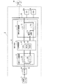
図1に示す車載システム1は、車両に搭載され、外部ツール(車外装置)3を接続するためのコネクタ40と、ゲートウェイECU(GW−ECU)10と、他の複数のECU20a、20b、…とを備える。
Embodiments to which the present invention is applied will be described below with reference to the drawings.
[1. First Embodiment]
[1-1. overall structure]
An in-
外部ツール3は、コネクタ40及び外部用バス50を介してGW−ECU10と相互通信可能に接続される。また、GW−ECU10及び他の複数のECU20a、20b、…は、共通の通信路である内部用バス30に接続されてネットワーク(車内LAN)を構築し、内部用バス30を介してCAN(Controller Area Network)プロトコルに従った相互通信を行う。なお以下では、ECU20a、ECU20b、…のように複数備えられた同一の構成については、個々について説明する場合を除き、ECU20といったように符号のアルファベットを省略して記載する。
The external tool 3 is connected to the GW-ECU 10 via the
GW−ECU10は、外部用バス50と内部用バス30とを中継する通信路上に設置されている。つまり、GW−ECU10は、外部ツール3と直接通信を行い、ECU20は、GW−ECU10を介して外部ツール3と通信を行う。また、GW−ECU10は、ECU20と直接通信を行い、外部ツール3は、GW−ECU10を介してECU20と通信を行う。このように、外部ツール3とECU20とは互いに直接接続されるのではなく、GW−ECU10を介して接続され、GW−ECU10は、外部ツール3とECU20との間で行われる通信を中継する中継装置として機能する。
The GW-ECU 10 is installed on a communication path that relays between the
GW−ECU10は、車内LAN通信部11、外部ツール通信部12、GW記憶部13、及びゲートウェイ制御部(GW制御部)14を備える。
車内LAN通信部11は、内部用バス30を介してECU20と通信を行うためのインタフェースであり、ドライバ111とレシーバ112とを備える。ドライバ111は、GW制御部14から出力された通信フレームに含まれるデータが、「1」のときにデータ(のビット値)「1」に対応する劣位状態信号(レセッシブという)を内部用バス30に送出し、「0」のときにデータ(のビット値)「0」に対応する優位状態信号(ドミナントという)を内部用バス30に送出する。レシーバ112は、内部用バス30を介してレセッシブが入力されたときにレセッシブに対応するデータ(「1」)をGW制御部14へ出力し、ドミナントが入力されたときにドミナントに対応するデータ(「0」)をGW制御部14へ出力する。
The GW-ECU 10 includes an in-vehicle
The in-vehicle
外部ツール通信部12は、外部用バス50を介してコネクタ40に接続された外部ツール3と通信を行うためのインタフェースであり、ドライバ121とレシーバ122とを備える。ドライバ121は、GW制御部14から出力された通信フレームに含まれるデータが「1」のときに、データ(のビット値)「1」に対応するレセッシブを外部用バス50に送出、「0」のときにデータ(のビット値)「0」に対応するドミナントを内部用バス30に送出する。レシーバ122は、外部用バス50を介してレセッシブが入力されたときにレセッシブに対応するデータ(「1」)をGW制御部14へ出力し、ドミナントが入力されたときにドミナントに対応するデータ(「0」)をGW制御部14へ出力する。
The external
GW制御部14は、CPU41、ROM42、RAM43等を備える周知のマイクロプロセッサを備え、例えばROM42等に記憶されたプログラムに従い、外部ツール3とECU20との間で行われる通信(通信フレームに含まれるデータの送受信)を中継する処理や、後述する不正フレーム対応処理を実行する。なお、本実施形態の車載システム1では、車両のイグニッションスイッチがオフ状態でもGW−ECU10に電源が供給され、CPU41が不正フレーム対応処理を実行できるように構成されている。
The
ゲートウェイ(GW)記憶部13は、電気的に記憶内容の書換えが可能な不揮発性の記憶装置(例えば、フラッシュメモリ、EEPROM等)を備える。GW記憶部13には、複数の識別データが記憶されている。識別データとは、車載システム1において内部用バス30及び外部用バス50を介して外部ツール3とECU20との間で通信が行われる単位、すなわちデータが送受信される単位である通信フレームの所定の領域に含まれているデータのことであり、当該通信フレームを識別するための複数のビットからなるデータである。本実施形態では一例として、周知のCANプロトコルの通信フレーム(データフレーム、リモートフレーム)のフォーマットにおける、アービトレーションフィールドに含まれているデータを識別データというものとする。
The gateway (GW)
具体的には、図2に示すように、外部ツール3からECU20aへ送信される通信フレームの識別データ、外部ツール3からECU20bへ送信される通信フレームの識別データ、ECU20bからECU20aへ送信される通信フレームの識別データ、…というように、その通信フレームが送信される送信元と送信先の組み合わせを表すデータが、識別データとして、GW記憶部13に記憶されている。なお、識別データは、図2において例えば「7X1(Xは0〜9の任意の整数)」のように10進数で表されている数字を2進数で表したデータである。本実施形態では、GW記憶部13に記憶されている識別データを許可データというものとする。
Specifically, as shown in FIG. 2, communication frame identification data transmitted from the external tool 3 to the
複数のECU20としては、例えば、エンジン制御を行うエンジンECU、ブレーキ制御を行うブレーキECU、ステアリング制御を行うステアリングECU等、各種機能を有するものが挙げられる。ECU20は、図示しないが、一例として、制御部(CPU)と、記憶部(例えば、フラッシュメモリ等)と、通信部と、を備える。記憶部には、各種機能を実現するための処理を制御部(CPU)に実行させるためのプログラムが記憶されている。制御部(CPU)は、記憶部に記憶されたプログラムに従い処理を実行する。通信部は、内部用バス30を介してGW−ECU10や他のECU20と通信を行うためのインタフェースである。
Examples of the plurality of ECUs 20 include those having various functions such as an engine ECU that performs engine control, a brake ECU that performs brake control, and a steering ECU that performs steering control. Although not shown, the ECU 20 includes, as an example, a control unit (CPU), a storage unit (for example, a flash memory), and a communication unit. The storage unit stores a program for causing the control unit (CPU) to execute processing for realizing various functions. The control unit (CPU) executes processing according to a program stored in the storage unit. The communication unit is an interface for communicating with the GW-
外部ツール3は、車載システム1(コネクタ40)に接続された状態で、ECU20を介した車両状態の診断、データ(セキュリティ関連情報等)の設定及び解除、GW−ECU10やECU20に記憶されているプログラムの書換処理などを行う。
The external tool 3 is stored in the GW-
外部ツール3は、図示しないが、制御部(CPU)と、記憶部(例えば、フラッシュメモリ等)と、通信部と、を備える。記憶部には、各種機能を実現するための処理を制御部(CPU)に実行させるためのプログラムが保存されている。制御部(CPU)は、記憶部に記憶されたプログラムに従い各種処理を実行する。通信部は、コネクタ40を介してGW−ECU10やECU20と通信を行うためのインタフェースである。なお、外部ツール3は、汎用のパーソナルコンピュータやスマートフォン(多機能型携帯電話機)などを用いて構成してもよい。
Although not shown, the external tool 3 includes a control unit (CPU), a storage unit (for example, a flash memory), and a communication unit. The storage unit stores a program for causing the control unit (CPU) to execute processing for realizing various functions. The control unit (CPU) executes various processes according to the program stored in the storage unit. The communication unit is an interface for communicating with the GW-
このような構成を備える、CANプロトコルに従った相互通信を行う通信システムである車載システム1では、内部用バス30を介した通信を例に挙げて説明すると、ノードとして機能するGW−ECU10(車内LAN通信部11)及びECU20(通信部)は、前述のように、データのビット値に対応する劣位状態信号(レセッシブ)及び優位状態信号(ドミナント)の2つの状態信号のうちいずれかを内部用バス30に順に出力することによって、通信フレームに含まれる各データを内部用バス30に送信する。
In the in-
また、車載システム1では、前述のように、GW−ECU10(車内LAN通信部11)及びECU20(通信部)は、内部用バス30を介してレセッシブ又はドミナントを順に入力することによって内部用バス30から通信フレームに含まれるデータを受信し、且つ、複数のノードからレセッシブ及びドミナントの両方が内部用バス30に出力されたときにドミナントに対応するデータを内部用バス30におけるデータとして受信する。
Further, in the in-
また、車載システム1に適用されているCANプロトコルでは、内部用バス30を介して受信されている通信フレームに含まれるデータのパターン(並び)において予め規定されたエラーがノードのいずれかによって検出されると、当該通信フレームを無効にするように規定されている。このようなエラーとしては周知のように、同一の状態信号(ドミナント、又はレセッシブ)が6ビット連続するスタッフ・エラーの他、ビットエラー、CRCエラー、フォームエラー、ACKエラーが規定されている。なお、内部用バス30を介した通信を例に挙げて説明したが、車載システム1において外部用バス50を介した通信も同様に行われる。
In the CAN protocol applied to the in-
[1−2.処理]
次に、GW−ECU10のCPU41が実行する不正フレーム対応処理を、図3に示すフローチャートに従って説明する。
[1-2. processing]
Next, the illegal frame handling process executed by the
はじめに、S(ステップ)100では、内部用バス30を介して通信フレームを受信する。具体的には、内部用バス30に送信されている通信フレームに含まれる各データを、内部用バス30から入力された状態信号(ドミナント、又はレセッシブ)に基づいて順に受信する。
First, in S (step) 100, a communication frame is received via the
S110では、S100にて受信された通信フレームに含まれる識別データに基づいて、当該通信フレームが不正であるか否かを判断する。具体的には、S100にて受信された通信フレームに含まれる識別データが、GW記憶部13に予め記憶されている許可データに一致しない場合に、当該通信フレームが不正であると判断する。つまり、仮にGW記憶部13に記憶されていない識別データを含む通信フレームが内部用バス30に送信されたとすると、この通信フレームは、内部用バス30に不正に接続された非正規の外部ツール(例えば、図1にて二点鎖線で示す不正ツール90)等による、不正な通信フレームであると判断される。ここで、通信フレームが不正でないと判断された場合、本不正フレーム対応処理を終了する。一方、通信フレームが不正であると判断された場合、S120へ移行する。
In S110, based on the identification data included in the communication frame received in S100, it is determined whether or not the communication frame is illegal. Specifically, when the identification data included in the communication frame received in S100 does not match the permission data stored in advance in the
S120では、通信フレームの送信中にエラー条件が満たされるように、車内LAN通信部11を用いて、内部用バス30にドミナントを送出させる。具体的には、スタッフ・エラーを生じさせるように、車内LAN通信部11に、6ビット連続したドミナントを送信させる。そして、本不正フレーム対応処理を終了する。
In S120, a dominant is sent to the
[1−3.効果]
以上詳述した第1実施形態によれば、以下の効果が得られる。
[1A]内部用バス30において不正であると判断された通信フレームは、当該通信フレームの送信途中であっても無効とされる。このため、仮に内部用バス30に非正規の外部ツール(不正ツール90)が接続され、この非正規の外部ツールから内部用バス30へ不正な通信フレームが送信されたとしても、この不正な通信フレームは、不正であると判断され次第無効とされる。つまり、正規の外部ツールが行うようなデータ(セキュリティ関連情報等)の設定及び解除、GW−ECU10やECU20に記憶されているプログラムの書換処理等を行うための不正な通信フレームが非正規の外部ツールから送信された場合に、不正な通信フレームの内容に基づく処理が行われることを抑制することができる。
[1-3. effect]
According to the first embodiment described in detail above, the following effects can be obtained.
[1A] A communication frame determined to be illegal on the
[1B]不正フレーム対応処理では、スタッフ・エラーを生じさせる条件を満たすように、6ビット連続したドミナントが送信される(S120)。これによると、内部用バス30から通信フレームに含まれるデータを受信したタイミングに関係無く、任意のタイミングで、不正な通信フレームを無効にすることができる。
[1B] In the illegal frame handling process, a 6-bit continuous dominant is transmitted so as to satisfy the condition for causing a stuff error (S120). According to this, an illegal communication frame can be invalidated at an arbitrary timing regardless of the timing at which data included in the communication frame is received from the
なお、本実施形態では、GW−ECU10が「通信装置」の一例に相当し、GW記憶部13が「記憶手段」の一例に相当する。S100が「受信手段」としての処理の一例に相当し、S110が「判定手段」としての処理の一例に相当し、S120が「送出手段」としての処理の一例に相当する。また、CANプロトコルが通信プロトコルの一例に相当する。
In the present embodiment, the GW-
[2.第2実施形態]
[2−1.構成]
第2実施形態は、基本的な構成は第1実施形態と同様であるため、共通する構成については説明を省略し、相違点を中心に説明する。
[2. Second Embodiment]
[2-1. Constitution]
Since the basic configuration of the second embodiment is the same as that of the first embodiment, the description of the common configuration will be omitted, and the description will focus on the differences.
第2実施形態では、図4に示すように、図1に示すGW記憶部13が削除されている点、図1に示す車内LAN通信部11に検出回路113が追加されている点、及びこれに伴うGW制御部14のCPU41が実行する不正フレーム対応処理の内容、が第1実施形態と相違する。
In the second embodiment, as shown in FIG. 4, the
具体的には、車内LAN通信部11に追加された検出回路113は、レシーバ112から順に出力されたデータの並びに基づいて、内部用バス30から受信している通信フレームの所定の領域(本実施形態では前述のアービトレーションフィールド)に含まれていた識別データが、所定の非正規データに一致するか否かを比較した結果である判定フラグFを生成する比較回路(図示せず)を備える。比較回路は、通信フレームに含まれていた識別データが非正規データに一致する場合に判定フラグFを1にセットし(F=1)、一致しない場合に0にセット(リセット、F=0)する。判定フラグFはGW制御部14へ出力される。
Specifically, the
ここでは、所定の非正規データとは、正規でないノードから送信される通信フレームに含まれ得る識別データをいう。例えば、内部用バス30に不正に接続された非正規の外部ツール(図4にて二点鎖線で示す不正ツール90)等から送信される、不正な通信フレームに含まれ得る識別データが既知である場合、この既知の識別データを非正規データとする。
Here, the predetermined irregular data refers to identification data that can be included in a communication frame transmitted from an unauthorized node. For example, identification data that can be included in an unauthorized communication frame transmitted from an unauthorized external tool (an
なお、非正規データが複数種類ある場合、検出回路113は、非正規データごとに比較回路を備える。そして、検出回路113は、これら複数の比較回路のうちいずれか一つの比較回路において通信フレームの所定の領域に含まれていた識別データが非正規データに一致する場合に、判定フラグFをセットする。これらの各比較回路は、言い換えれば、図1に示すGW記憶部13に代えて各識別データ(本実施形態では非正規データ)を記憶するものであると言える。
When there are a plurality of types of non-normal data, the
[2−2.処理]
次に、GW制御部14(CPU41)が実行する不正フレーム対応処理を図5に示すフローチャートに従って説明する。図5に示すフローチャートでは、図3に示すS100が削除され、S110がS115に置換されている。
[2-2. processing]
Next, the illegal frame handling process executed by the GW control unit 14 (CPU 41) will be described with reference to the flowchart shown in FIG. In the flowchart shown in FIG. 5, S100 shown in FIG. 3 is deleted, and S110 is replaced with S115.
S115では、内部用バス30を介して車内LAN通信部11にて受信された通信フレームに含まれる識別データに基づいて、当該通信フレームが不正であるか否かを判断する。具体的には、検出回路113から出力された判定フラグFがセットされている場合に、当該通信フレームが不正であると判断する。ここで、判定フラグFがセットされていない場合(F=0)、本不正フレーム対応処理を終了する。一方、判定フラグFがセットされている場合(F=1)、S120へ移行し、図3に示すS120と同様に、スタッフ・エラーを生じさせるように、車内LAN通信部11に、6ビット連続したドミナントを送出させる。すなわち、車内LAN通信部11のドライバ111に6ビット連続したデータ「0」を送信することによって、車内LAN通信部11(ドライバ111)から内部用バス30にドミナントを送出させる。そして、本不正フレーム対応処理を終了する。
In S115, based on the identification data included in the communication frame received by the in-vehicle
[2−3.効果]
以上詳述した第2実施形態によれば、前述した第1実施形態の効果[1A]及び[1B]に加え、以下の効果が得られる。
[2-3. effect]
According to the second embodiment described in detail above, the following effects are obtained in addition to the effects [1A] and [1B] of the first embodiment described above.
[2A]内部用バス30を介して受信している通信フレームが不正であるか否かが比較回路によって検出されるため、検出結果を迅速に得ることができる。また、比較回路の検出結果である判定フラグFに基づいて不正フレーム対応処理が実行されるため、通信フレームが不正であると判断された場合に当該通信フレームを無効にする処理を、迅速に行うことができる。
[2A] Since the comparison circuit detects whether or not the communication frame received via the
なお、第2実施形態では、レシーバ112が「受信手段」の一例に相当し、検出回路113が「判定手段」及び「記憶手段」の一例に相当し、ドライバ111が送出手段の一例に相当する。
In the second embodiment, the
[3.他の実施形態]
以上、本発明の実施形態について説明したが、本発明は、上記実施形態に限定されることなく、種々の形態を採り得ることは言うまでもない。
[3. Other Embodiments]
As mentioned above, although embodiment of this invention was described, it cannot be overemphasized that this invention can take a various form, without being limited to the said embodiment.
[3A]上記実施形態では、スタッフ・エラーを生じさせるように、内部用バス30にドミナントを送出したが、これに限らず、ビットエラー、CRCエラー、フォームエラー、及びACKエラーのいずれかを生じさせるように、内部用バス30にドミナントを送出してもよい。
[3A] In the above embodiment, a dominant is transmitted to the
[3B]上記実施形態では、スタッフ・エラーを生じさせるように、6ビット連続したドミナントを送出したが、これに限らず、例えば、7ビット以上連続したドミナントを送出してもよい。または、S100にて受信した通信フレームに含まれるドミナントを含めて6ビット連続するように、ドミナントを送出してもよい。 [3B] In the above embodiment, 6-bit continuous dominants are transmitted so as to cause a stuff error. However, the present invention is not limited to this. For example, 7-bit continuous dominants may be transmitted. Or you may transmit a dominant so that it may continue 6 bits including the dominant contained in the communication frame received in S100.
[3C]上記実施形態における1つの構成要素が有する機能を複数の構成要素として分散させたり、複数の構成要素が有する機能を1つの構成要素に統合したりしてもよい。また、上記実施形態の構成の少なくとも一部を、同様の機能を有する公知の構成に置き換えてもよい。また、上記実施形態の構成の一部を、課題を解決できる限りにおいて省略してもよい。また、上記実施形態の構成の少なくとも一部を、他の上記実施形態の構成に対して付加、置換等してもよい。なお、特許請求の範囲に記載の文言から特定される技術思想に含まれるあらゆる態様が本発明の実施形態である。 [3C] The functions of one component in the above embodiment may be distributed as a plurality of components, or the functions of a plurality of components may be integrated into one component. Further, at least a part of the configuration of the above embodiment may be replaced with a known configuration having the same function. Moreover, you may abbreviate | omit a part of structure of the said embodiment as long as a subject can be solved. In addition, at least a part of the configuration of the above embodiment may be added to or replaced with the configuration of the other embodiment. In addition, all the aspects included in the technical idea specified from the wording described in the claims are embodiments of the present invention.
[3C]本発明は、前述したGW−ECU10及び車載システム1、2の他、GW−ECU10としてコンピュータを機能させるためのプログラム、このプログラムを記録した媒体、通信方法など、種々の形態で実現することができる。
[3C] The present invention is implemented in various forms such as the above-described GW-
1、2…車載システム 3…外部ツール 10…GW−ECU、11…車内LAN通信部 13…GW記憶部 14…GW制御部 15…車内LAN通信部20…ECU 30…内部用バス 50…外部用バス 111…ドライバ 112…レシーバ 113…検出回路。
DESCRIPTION OF
Claims (4)
前記通信フレームを受信する受信手段(11、112、S100)と、
前記受信手段によって受信された前記通信フレームに含まれる前記識別データに基づいて当該通信フレームが不正であると判定する判定手段(113、S110)と、
前記判定手段により前記通信フレームが不正であると判定された場合に、当該通信フレームの送信中に前記エラー条件が満たされるように、前記通信路に前記優位状態信号を送出する送出手段(11、111、S120)と、
を備えることを特徴とする通信装置(1、2)。 A communication system in which a plurality of nodes transmit and receive a communication frame including identification data via a common communication path, wherein the communication frame is superior to the inferior state signal and the inferior state signal in the communication path. Are transmitted by sequentially transmitting from the node to the communication path, and the inferior state signal transmitted to the communication path and the pattern of the superior state signal are defined in advance as error conditions. A communication device that functions as the node in a communication system in which each of the plurality of nodes performs communication in accordance with a communication protocol defined such that the communication frame being transmitted is invalidated when the communication frame is satisfied;
Receiving means (11, 112, S100) for receiving the communication frame;
Determining means (113, S110) for determining that the communication frame is invalid based on the identification data included in the communication frame received by the receiving means;
Sending means (11, 11) for sending the superiority state signal to the communication path so that the error condition is satisfied during transmission of the communication frame when the determination means determines that the communication frame is invalid. 111, S120),
A communication device (1, 2) characterized by comprising:
正規の前記ノードから送信される前記通信フレームに含まれ得る前記識別データを許可データとして予め記憶している記憶手段(13)を備え、
前記判定手段は、前記受信手段によって受信された前記通信フレームに含まれる前記識別データが前記許可データに一致しない場合に、当該通信フレームが不正であると判定する
ことを特徴とする通信装置(1)。 The communication device according to claim 1,
Comprising storage means (13) for preliminarily storing the identification data that can be included in the communication frame transmitted from the regular node as permission data;
The determination unit determines that the communication frame is invalid when the identification data included in the communication frame received by the reception unit does not match the permission data. ).
正規でない前記ノードから送信される前記通信フレームに含まれ得る前記識別データを非正規データとして予め記憶している記憶手段(113)を備え、
前記判定手段は、前記受信手段によって受信された前記通信フレームに含まれる前記識別データが前記非正規データに一致する場合に、当該通信フレームが不正であると判定する
ことを特徴とする通信装置(2)。 The communication device according to claim 1 or 2,
Storage means (113) for storing the identification data that can be included in the communication frame transmitted from the non-regular node as non-regular data;
The determination unit determines that the communication frame is invalid when the identification data included in the communication frame received by the receiving unit matches the non-regular data. 2).
前記エラー条件は、前記優位状態信号が所定の回数以上連続するという条件である
ことを特徴とする通信装置。 The communication device according to any one of claims 1 to 3,
The error condition is a condition that the superiority state signal continues for a predetermined number of times or more.
Priority Applications (1)
| Application Number | Priority Date | Filing Date | Title |
|---|---|---|---|
| JP2014088336A JP2015207937A (en) | 2014-04-22 | 2014-04-22 | Communication apparatus |
Applications Claiming Priority (1)
| Application Number | Priority Date | Filing Date | Title |
|---|---|---|---|
| JP2014088336A JP2015207937A (en) | 2014-04-22 | 2014-04-22 | Communication apparatus |
Publications (1)
| Publication Number | Publication Date |
|---|---|
| JP2015207937A true JP2015207937A (en) | 2015-11-19 |
Family
ID=54604436
Family Applications (1)
| Application Number | Title | Priority Date | Filing Date |
|---|---|---|---|
| JP2014088336A Pending JP2015207937A (en) | 2014-04-22 | 2014-04-22 | Communication apparatus |
Country Status (1)
| Country | Link |
|---|---|
| JP (1) | JP2015207937A (en) |
Cited By (1)
| Publication number | Priority date | Publication date | Assignee | Title |
|---|---|---|---|---|
| JP2015227157A (en) * | 2014-05-30 | 2015-12-17 | 以勤科技股▲分▼有限公司 | Data gateway, and method for interfering with vehicular operation thereof |
Citations (4)
| Publication number | Priority date | Publication date | Assignee | Title |
|---|---|---|---|---|
| JP2002094535A (en) * | 2000-09-01 | 2002-03-29 | Motorola Inc | Error code transmitter and its method |
| WO2010140193A1 (en) * | 2009-06-04 | 2010-12-09 | トヨタ自動車株式会社 | Data relay device and data relay method used in the device |
| JP2013187555A (en) * | 2012-03-05 | 2013-09-19 | Auto Network Gijutsu Kenkyusho:Kk | Communication system |
| JP2013192091A (en) * | 2012-03-14 | 2013-09-26 | Denso Corp | Communication system, relay device, out-vehicle device and communication method |
-
2014
- 2014-04-22 JP JP2014088336A patent/JP2015207937A/en active Pending
Patent Citations (4)
| Publication number | Priority date | Publication date | Assignee | Title |
|---|---|---|---|---|
| JP2002094535A (en) * | 2000-09-01 | 2002-03-29 | Motorola Inc | Error code transmitter and its method |
| WO2010140193A1 (en) * | 2009-06-04 | 2010-12-09 | トヨタ自動車株式会社 | Data relay device and data relay method used in the device |
| JP2013187555A (en) * | 2012-03-05 | 2013-09-19 | Auto Network Gijutsu Kenkyusho:Kk | Communication system |
| JP2013192091A (en) * | 2012-03-14 | 2013-09-26 | Denso Corp | Communication system, relay device, out-vehicle device and communication method |
Non-Patent Citations (2)
| Title |
|---|
| 畑 正人 他: "CANにおける不正送信阻止方式の実装と評価", 電子情報通信学会技術研究報告, vol. 第112巻,第342号, JPN6017023283, 5 December 2012 (2012-12-05), pages 15 - 22, ISSN: 0003723543 * |
| 関口 大樹 他: "不正CAN通信阻止のためのECU内蔵監視機構", 電子情報通信学会技術研究報告, vol. 第112巻,第462号, JPN6017023284, 28 February 2013 (2013-02-28), pages 203 - 210, ISSN: 0003584777 * |
Cited By (1)
| Publication number | Priority date | Publication date | Assignee | Title |
|---|---|---|---|---|
| JP2015227157A (en) * | 2014-05-30 | 2015-12-17 | 以勤科技股▲分▼有限公司 | Data gateway, and method for interfering with vehicular operation thereof |
Similar Documents
| Publication | Publication Date | Title |
|---|---|---|
| CN107683589B (en) | Vehicle-mounted relay device and vehicle-mounted communication system | |
| CN106031098B (en) | Abnormal frame coping method, abnormal detection electronic control unit and vehicle-mounted network system | |
| JP6836340B2 (en) | Fraud detection electronic control unit, in-vehicle network system and communication method | |
| US11036853B2 (en) | System and method for preventing malicious CAN bus attacks | |
| US20150230044A1 (en) | Updating vehicle software using a smartphone | |
| WO2017038500A1 (en) | Relay device | |
| US9894081B2 (en) | Method and device for avoiding manipulation of a data transmission | |
| JP6369341B2 (en) | In-vehicle communication system | |
| JP2016201740A (en) | On-vehicle communication system, repeating device, and node | |
| US20170155679A1 (en) | Method of preventing drive-by hacking, and apparatus and system therefor | |
| JP2016163348A (en) | One-way gateway, vehicle network system and method for protecting network within vehicle using one-way gateway | |
| US11070547B2 (en) | Electronic control device, a communication management method performable and a non-transitory storage medium configured to restrict predetermined communication in an in-vehicle network | |
| KR102471960B1 (en) | Apparatus for security of vehicle can communication and method thereof | |
| US20170187567A1 (en) | Electronic control apparatus | |
| JP6544250B2 (en) | Relay device | |
| JP2015207937A (en) | Communication apparatus | |
| JP6390398B2 (en) | In-vehicle network system | |
| JP6620696B2 (en) | Electronic control unit | |
| JP2015192216A (en) | Communication device and communication method | |
| JP2018166309A (en) | In-vehicle network system, electronic control device, communication method and computer program | |
| JP2018164232A (en) | Communication system, relay device, communication method, and computer program | |
| KR102001420B1 (en) | Electronic Control Unit, Communication Security System and Method for Vehicle | |
| JP2016146605A (en) | On-vehicle communication device | |
| JP6183281B2 (en) | Communication system and electronic control device | |
| JP2013121071A (en) | Relay system, and relay device and external device forming the same |
Legal Events
| Date | Code | Title | Description |
|---|---|---|---|
| A621 | Written request for application examination |
Free format text: JAPANESE INTERMEDIATE CODE: A621 Effective date: 20160721 |
|
| A977 | Report on retrieval |
Free format text: JAPANESE INTERMEDIATE CODE: A971007 Effective date: 20170510 |
|
| A131 | Notification of reasons for refusal |
Free format text: JAPANESE INTERMEDIATE CODE: A131 Effective date: 20170627 |
|
| A521 | Request for written amendment filed |
Free format text: JAPANESE INTERMEDIATE CODE: A523 Effective date: 20170828 |
|
| A02 | Decision of refusal |
Free format text: JAPANESE INTERMEDIATE CODE: A02 Effective date: 20180123 |