JP2015207648A - Solar cell module - Google Patents
Solar cell module Download PDFInfo
- Publication number
- JP2015207648A JP2015207648A JP2014086988A JP2014086988A JP2015207648A JP 2015207648 A JP2015207648 A JP 2015207648A JP 2014086988 A JP2014086988 A JP 2014086988A JP 2014086988 A JP2014086988 A JP 2014086988A JP 2015207648 A JP2015207648 A JP 2015207648A
- Authority
- JP
- Japan
- Prior art keywords
- sol
- phosphor
- group
- solar cell
- gel
- Prior art date
- Legal status (The legal status is an assumption and is not a legal conclusion. Google has not performed a legal analysis and makes no representation as to the accuracy of the status listed.)
- Pending
Links
Images
Classifications
-
- Y—GENERAL TAGGING OF NEW TECHNOLOGICAL DEVELOPMENTS; GENERAL TAGGING OF CROSS-SECTIONAL TECHNOLOGIES SPANNING OVER SEVERAL SECTIONS OF THE IPC; TECHNICAL SUBJECTS COVERED BY FORMER USPC CROSS-REFERENCE ART COLLECTIONS [XRACs] AND DIGESTS
- Y02—TECHNOLOGIES OR APPLICATIONS FOR MITIGATION OR ADAPTATION AGAINST CLIMATE CHANGE
- Y02E—REDUCTION OF GREENHOUSE GAS [GHG] EMISSIONS, RELATED TO ENERGY GENERATION, TRANSMISSION OR DISTRIBUTION
- Y02E10/00—Energy generation through renewable energy sources
- Y02E10/50—Photovoltaic [PV] energy
- Y02E10/52—PV systems with concentrators
Landscapes
- Photovoltaic Devices (AREA)
Abstract
Description
本発明は、光電変換素子の前面に蛍光体を配置してなる太陽電池モジュールに関するものである。 The present invention relates to a solar cell module in which a phosphor is disposed on the front surface of a photoelectric conversion element.
太陽電池は一般に短波長領域において感度特性が低く、太陽光に含まれる紫外線などの短波長領域の光を有効に利用できていない。その課題を解決する手段として、従来からこの短波長領域の光を吸収し、長波長領域の蛍光を発する蛍光体(いわゆる波長変換材料)を用いる方法があった。この方法では、使用されていなかった短波長領域の光を、長波長領域の光へ変換する。このことで、光量を増加させ、太陽電池の変換効率を向上させる取組みが行われてきた。 Solar cells generally have low sensitivity characteristics in the short wavelength region and cannot effectively use light in the short wavelength region such as ultraviolet rays contained in sunlight. As a means for solving the problem, there has conventionally been a method of using a phosphor (so-called wavelength conversion material) that absorbs light in the short wavelength region and emits fluorescence in the long wavelength region. In this method, light in a short wavelength region that has not been used is converted into light in a long wavelength region. Thus, efforts have been made to increase the amount of light and improve the conversion efficiency of the solar cell.
例えば、特許文献1や特許文献2においては、ポリアクリレート系の透明樹脂中に有機蛍光体を溶解し得られる重合体を短波長部の光をより長波長の光へ効率よく変換できる優れた成形体を開示している。 For example, in Patent Document 1 and Patent Document 2, a polymer obtained by dissolving an organic phosphor in a polyacrylate-based transparent resin can be efficiently converted from light having a short wavelength portion to light having a longer wavelength. The body is disclosed.
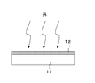
また、特許文献3では、図5に示すように、アクリル樹脂、エポキシ樹脂、シリコーン樹脂、エチレンビニルアセテート(EVA)樹脂といった有機系の透明樹脂11に、蛍光体を含有させた波長変換層12を設ける部材を用いる提案している。
Further, in Patent Document 3, as shown in FIG. 5, a
また、特許文献4では、太陽電池モジュールにおいて光電変換素子の保護樹脂であるエチレン−酢酸ビニル共重合体中に、レアアース系の蛍光体を配合し、効率向上を行う提案がなされている。 Further, Patent Document 4 proposes to improve efficiency by blending a rare earth phosphor in an ethylene-vinyl acetate copolymer that is a protective resin for a photoelectric conversion element in a solar cell module.
以上のような課題解決に向けた取組みは知られているものの、上記従来技術では波長変換層に含有させる蛍光体には屋外使用という観点から高い耐候性が求められる。
特に、有機化合物からなる蛍光体の場合、透明な波長変換層に溶存させることにより透明性の高い層とすることができるが、酸素や水などとの反応による劣化が早く、その性能を十分に維持することができない。
Although efforts to solve the above problems are known, in the above-described conventional technology, the phosphor to be contained in the wavelength conversion layer is required to have high weather resistance from the viewpoint of outdoor use.
In particular, in the case of a phosphor made of an organic compound, it can be made a highly transparent layer by dissolving it in a transparent wavelength conversion layer, but its deterioration due to reaction with oxygen, water, etc. is quick, and its performance is sufficient. It cannot be maintained.
本願課題は、波長変換材料の劣化を抑え、その性能を十分に維持することである。 An object of the present application is to suppress deterioration of the wavelength conversion material and maintain its performance sufficiently.
上記課題を解決するため、光電変換素子と、光電変換素子が配置された第一の透明樹脂と、光電変換素子と電気的に接続された電極と、第一の透明樹脂の下部に配置されたバックシートと、第一の透明樹脂の上部に配置された保護ガラスと、保護ガラスに配置され、蛍光体を含有するゾルゲル硬化体層と、を備えた太陽電池モジュールであって、ゾルゲル硬化体層の中に、無機充填材が配合されていることを特徴とする太陽電池モジュールを用いる。 In order to solve the above problem, a photoelectric conversion element, a first transparent resin in which the photoelectric conversion element is disposed, an electrode electrically connected to the photoelectric conversion element, and a lower portion of the first transparent resin are disposed. A solar cell module comprising a back sheet, a protective glass disposed on an upper portion of the first transparent resin, and a sol-gel cured body layer disposed on the protective glass and containing a phosphor, the sol-gel cured body layer A solar cell module characterized in that an inorganic filler is blended therein.
本発明の太陽電池モジュールでは、ゾルゲル重合体に、ゾルゲル重合体と屈折率の近いフィラーを、充填した層を用いる。この高強度な層を、太陽電池のガラス表面に形成する。この層に蛍光体を含有させる。 In the solar cell module of the present invention, a layer in which a sol-gel polymer is filled with a filler having a refractive index close to that of the sol-gel polymer is used. This high-strength layer is formed on the glass surface of the solar cell. This layer contains a phosphor.
このことで、クラックが発生せず蛍光体が水や酸素による反応劣化から保護されている層とすることにより長寿命の波長変換膜とすることができる。 Thus, a long-life wavelength conversion film can be obtained by forming a layer in which the phosphor is protected from reaction deterioration due to water or oxygen without generating cracks.
以下、本発明の実施形態を図面に基づいて詳細に説明する。 Hereinafter, embodiments of the present invention will be described in detail with reference to the drawings.
(実施の形態1)
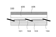
図1は、本発明の実施の形態1に係る太陽電池モジュール100の構造を示す断面図である。実施の形態1の太陽電池モジュール100では、少なくとも光電変換素子101と、光電変換素子101を保護する透明樹脂102と、バックシート103と、光電変換素子同士を接続しかつ外部へ得られた電流を取り出す電極104と、保護ガラス105と、保護ガラス上に形成され、蛍光体およびフィラーを含むゾルゲル重合体であるゾルゲル硬化体層106を備えている。
(Embodiment 1)
FIG. 1 is a cross-sectional view showing the structure of
光電変換素子101は、特に限定されるものではないが、単結晶シリコン系、多結晶シリコン系、アモルファスシリコン系などのシリコン半導体、ガリウム砒素、カドミウムテルルなどの化合物半導体などとすることができる。
The
電極104は、金属材料や合金材料とすることができる。
The
透明樹脂102は、特に限定するものではないが、エチレン酢酸ビニル共重合体、ビスフェノールエポキシ樹脂硬化物、アクリル樹脂、シリコーン樹脂、ポリカーボネート樹脂などとすることができる。
The
透明樹脂102は、光電変換素子101にとって、感度特性が低く劣化の原因となる350nm以下の光を吸収する公知の紫外線吸収剤が含有されていても良い。
The
保護ガラス105は、特に限定するものではなく、透光性および遮水性を有する板状ガラスとすることができる。
The
ゾルゲル硬化体層106は、保護ガラス105上に配置される。ゾルゲル硬化体層106は、蛍光体とフィラーを含む。フィラーは、ゾルゲル硬化体層106と屈折率が近いフィラーである。
The sol-gel cured
<ゾルゲル硬化体層106>
ゾルゲル硬化体層106は、少なくとも1種類以上の金属アルコキシドの重合により形成されたゾルゲル重合体からなる。さらに、ゾルゲル重合体には、蛍光体と、ゾルゲル重合体と屈折率の近い無機充填材であるフィラーと、が配合され分散している。
<Sol-gel hardened
The sol-gel cured
ゾルゲル重合体は、金属アルコキシドが、シリコンアルコキシドである場合には、シロキサン骨格とそれらが架橋された構造と、シリコン原子に、後述する有機官能基が結合している場合には、これら重合からなる3次元ネットワークポリマーを形成していても良い。 When the metal alkoxide is a silicon alkoxide, the sol-gel polymer is composed of a siloxane skeleton, a structure in which they are cross-linked, and a polymerization when an organic functional group described later is bonded to a silicon atom. A three-dimensional network polymer may be formed.
フィラーは例えばシリカフィラーなど、緻密なガラス構造を取る。このため、空気が透過することができず、フィラーが体積の一定部分を占めるため、ゾルゲル重合体の脱水縮合時の収縮によるクラックを抑制することが出来、含有している蛍光体を水や酸素から保護することができる。 The filler has a dense glass structure such as a silica filler. For this reason, since air cannot permeate and the filler occupies a certain part of the volume, cracks due to shrinkage during the dehydration condensation of the sol-gel polymer can be suppressed, and the contained phosphor can be treated with water or oxygen. Can be protected from.
また、ゾルゲル重合体および充填材の屈折率は1.4〜1.5程度であり、ゾルゲル硬化体層106の屈折率もまた1.4〜1.5程度となる。
The refractive index of the sol-gel polymer and the filler is about 1.4 to 1.5, and the refractive index of the sol-gel cured
一方、保護ガラス105の屈折率は1.5であり、このため入射光に対する反射防止効果による高効率化が期待できる。蛍光体による波長変換効果と併せて、さらに、光電変換効率を高くすることができる。
On the other hand, the refractive index of the
<ゾルゲル硬化体層106の構成>
ゾルゲル硬化体層106としては、限定するものではないが、ゾルゲル重合体と、ゾルゲル重合体に配合されたフィラーと、蛍光体と、から構成される。
<Configuration of sol-gel cured
Although it does not limit as the sol-gel hardened | cured
ゾルゲル重合体は、少なくとも1種類のアルコキシシランを出発原料とする。ゾルゲル重合体は、シロキサン骨格を基本とした硬化物であり、アルコキシシランのアルコキシ基の加水分解により生成するシラノール基同士の脱水縮合により、液相中でのゾル−ゲル法によって形成される。屈折率は約1.4〜1.5である。 The sol-gel polymer uses at least one kind of alkoxysilane as a starting material. The sol-gel polymer is a cured product based on a siloxane skeleton, and is formed by a sol-gel method in a liquid phase by dehydration condensation between silanol groups generated by hydrolysis of an alkoxy group of alkoxysilane. The refractive index is about 1.4 to 1.5.
<ゾルゲル硬化体層106の製法>
(ゾルの調整)
まず、アルコキシシランと水の混合物を酸性触媒下において加熱し、アルコキシ基を加水分解しシラノール基を生成させ、ゾルとする。
<Method for producing sol-gel cured
(Sol adjustment)
First, a mixture of alkoxysilane and water is heated under an acidic catalyst to hydrolyze the alkoxy group to produce a silanol group to obtain a sol.
アルコキシシランとしては、そのアルコキシ基数が2〜4とすることができ、Si(OR1)x(R2)4−xにより表される。xは2〜4の整数であり、2または3が好ましい。 As alkoxysilane, the alkoxy group number can be made into 2-4, and it is represented by Si (OR1) x (R2) 4-x . x is an integer of 2 to 4, and 2 or 3 is preferable.
xが、1の場合、アルコキシシランには一つのアルコキシ基しか存在せず、重合によりシロキサン骨格を形成することができない。xが4の場合、アルコキシシラン同士の重合は可能であるが、反応点が多くなるため収縮が大きくなり、クラックが発生し易くなる。 When x is 1, alkoxysilane has only one alkoxy group, and a siloxane skeleton cannot be formed by polymerization. When x is 4, alkoxysilanes can be polymerized, but the number of reaction points increases, so that shrinkage increases and cracks are likely to occur.
OR1は、加水分解時に立体障害が少なくシラノール基へと反応しやすいものがよい。また加水分解により発生するアルコールの分子量が小さく揮発しやすいものがよい。これらの観点から、炭素数1〜5のアルキル基が好ましい。 OR1 is preferably one that has little steric hindrance during hydrolysis and easily reacts with a silanol group. Also, the alcohol generated by hydrolysis should have a small molecular weight and easily volatilize. From these viewpoints, an alkyl group having 1 to 5 carbon atoms is preferable.
R2としては、限定するものではないが、例えば炭素数が1〜10の有機官能基とすることができる。炭素数が11より大きい官能基では、立体障害が大きくなり重合によりゾルゲル硬化体が形成される際に重合が阻害され、重合体の形成が困難となるためである。 Although it does not limit as R2, For example, it can be set as a C1-C10 organic functional group. When the functional group has a carbon number greater than 11, the steric hindrance increases, and when the sol-gel hardened body is formed by polymerization, the polymerization is inhibited and the formation of the polymer becomes difficult.
メチル基、エチル基、ビニル基、プロピル基、ブチル基、ヘキシル基、フェニル基、シクロヘキシル基、オクチル基、デシル基、アリル等の炭化水素基、及びγ−クロロプロピル、およびこれらの、水素がフッ素に置き換わったフルオロ炭化水素基、γ−メルカプトプロピル、γ−メタクリロイルオキシプロピル等の置換炭化水素基が挙げられる。 Methyl group, ethyl group, vinyl group, propyl group, butyl group, hexyl group, phenyl group, cyclohexyl group, octyl group, decyl group, allyl hydrocarbon group, and γ-chloropropyl, and hydrogen is fluorine And substituted hydrocarbon groups such as γ-mercaptopropyl, γ-methacryloyloxypropyl, and the like.
また、アルコキシシランとしては、反応性有機官能基を有していても良く、この場合にはYnSi(OR)4−nにより表されるアルコキシシランであり、Yをたとえばグリシドキシプロピル基や、スチリル基、アクリレート基、メチルメタクリレート基、ビニル基およびその誘導体、チオールプロピル基、アミノプロピル基等とすることができ、光反応、熱反応あるいはそれらの組合せなど反応誘起方法を適宜選択することが出来る。 The alkoxysilane may have a reactive organic functional group. In this case, it is an alkoxysilane represented by YnSi (OR) 4-n, and Y is, for example, a glycidoxypropyl group, It can be a styryl group, an acrylate group, a methyl methacrylate group, a vinyl group and derivatives thereof, a thiolpropyl group, an aminopropyl group, etc., and a reaction inducing method such as photoreaction, thermal reaction, or a combination thereof can be appropriately selected. .
上記のアルコキシシランは2種類以上を併用しても良い。特に、チオールプロピル基やアミノプロピル基は、グリシドキシプロピル基を重合させることができることから、グリシドキシプロピル基と好適に混合し用いることができる。 Two or more of the above alkoxysilanes may be used in combination. In particular, a thiolpropyl group or an aminopropyl group can be used by being suitably mixed with a glycidoxypropyl group because a glycidoxypropyl group can be polymerized.
(充填材の配合)
このようにして得られたゾル中に充填材を添加し分散させる。充填材の分散性を高めるために揮発性の有機溶媒を添加してもよく、充填材のゾル分散液を調整する。
(Formulation of filler)
A filler is added and dispersed in the sol thus obtained. In order to enhance the dispersibility of the filler, a volatile organic solvent may be added, and the sol dispersion of the filler is adjusted.
充填材としては限定するものではないが、ゾルゲル重合体と屈折率が近いものとしてシリカフィラーとすることができ、溶融シリカや破砕フィラーなどとすることが出来る。 Although it does not limit as a filler, it can be set as a silica filler as a thing with a refractive index close | similar to a sol-gel polymer, and can be set as a fused silica, a crushing filler, etc.
また、シリカフィラー表面を公知の方法によりアルコキシシランで処理することは、その処理された表面とゾルゲル重合体と相溶性が向上し、フィラー同士の凝集が抑制されるという点でさらに好ましい。 Further, it is more preferable to treat the silica filler surface with an alkoxysilane by a known method in that compatibility between the treated surface and the sol-gel polymer is improved, and aggregation of fillers is suppressed.
フィラーの平均粒径としては限定するものではないが、0.2μm以上100μm以下とすることが出来る。0.2μmよりも小さいと、凝集し易くなり均一分散し難くなるため白濁などがおこり、100μmより大きいと、沈降が激しく均一に分散することが困難となる。 The average particle size of the filler is not limited, but can be 0.2 μm or more and 100 μm or less. If it is smaller than 0.2 μm, it becomes easy to aggregate and difficult to uniformly disperse, resulting in white turbidity. If it is larger than 100 μm, it is difficult to disperse vigorously and uniformly.
フィラーの屈折率は、分散させた後に透明性が確保される必要からゾルゲル重合体の屈折率と近いという観点から1.3以上1.6以下とすることができ、1.4以上1.5以下ならば、ゾルゲル重合体の屈折率と同じであり、非常に透明となりよい。 The refractive index of the filler can be set to 1.3 or more and 1.6 or less from the viewpoint of being close to the refractive index of the sol-gel polymer from the need to ensure transparency after being dispersed, and 1.4 or more and 1.5 or less. Below, it is the same as the refractive index of the sol-gel polymer and can be very transparent.
1.3より小さいかもしくは1.6よりも大きいと、ゾルゲル硬化体層106の透明性が低くなり、太陽電池セルへの入射光を妨げ、効率低下の原因となる。
If it is smaller than 1.3 or larger than 1.6, the transparency of the sol-gel cured
また、充填材の添加量としては、上記で調整したゾルの重量に対して、その重量が1%以上70%以下とすることができ、さらに好ましくは2%以上、50%以下とすることができる。 The amount of the filler added may be 1% or more and 70% or less, more preferably 2% or more and 50% or less with respect to the weight of the sol adjusted as described above. it can.
1%より小さいと、硬化後のゾルゲル硬化体層としての強度が十分でなくなる。70%より大きい場合には、凝集し易くなり透明性を維持するのが困難となる。2%以上の場合、ガスバリア性が向上するという観点でさらに好ましい。50%より小さい場合、分散性を維持させ易く透明とし易いためさらに好ましい。 If it is less than 1%, the strength of the cured sol-gel cured body layer will be insufficient. If it is larger than 70%, it tends to aggregate and it becomes difficult to maintain transparency. In the case of 2% or more, it is more preferable from the viewpoint of improving gas barrier properties. If it is less than 50%, it is more preferable because it is easy to maintain dispersibility and make it transparent.
また、フィラーとしては、屈折率がゾルゲル重合体と近く、1.3以上1.6以上であればよく、例えばアルミナイト、フッ化ソーダ、フッ化カルシウム、フッ化ランタン、フッ化リチウム、フッ化マグネシウム、フッ化ストロンチウム、無水シリカ、フッ石、カオリン、タルク、セリサイト、ポリスチレン、ポリエチレン、ポリメタクリル酸メチル、ビニル樹脂などを使用することができる。 Further, the filler may have a refractive index close to that of the sol-gel polymer and may be 1.3 or more and 1.6 or more. For example, aluminite, sodium fluoride, calcium fluoride, lanthanum fluoride, lithium fluoride, fluoride Magnesium, strontium fluoride, anhydrous silica, fluorite, kaolin, talc, sericite, polystyrene, polyethylene, polymethyl methacrylate, vinyl resin, and the like can be used.
(蛍光体の配合)
このようにして得られた充填材分散ゾル中に蛍光体を添加し溶解する。蛍光体の溶解度を高めるために揮発性の有機溶媒を添加してもよく、蛍光体のゾル溶液を調整する。得られた蛍光体のゾル溶液をガラスに塗布し乾燥させ、ゾルゲル反応によりゾル溶液中のシラノール同士の脱水縮合反応を進行させることにより、先に配合した充填材および蛍光体を含有したゾルゲル硬化体層の原液を得ることができる。
(Phosphor mix)
The phosphor is added and dissolved in the filler-dispersed sol thus obtained. In order to increase the solubility of the phosphor, a volatile organic solvent may be added to adjust the sol solution of the phosphor. The obtained phosphor sol solution is applied to glass and dried, and a sol-gel hardened body containing a filler and a phosphor previously blended by advancing a dehydration condensation reaction between silanols in the sol solution by a sol-gel reaction. A stock solution of the layer can be obtained.
蛍光体としては組成、系統共に限定されるものではないが、無機化合物、有機化合物、無機−有機錯体化合物などを単独もしくは併用などし、適宜使用することができる。実施の形態1においては、太陽電池の感度特性の低い波長の光を吸収し、感度特性の高い波長の光を蛍光として発し、光電変換効率を向上させるという観点から、400nm以下の紫外光を吸収し、400nmより長い波長の蛍光を発することが好ましい。 The phosphor and composition are not limited in both composition and system, but inorganic compounds, organic compounds, inorganic-organic complex compounds, etc. can be used alone or in combination as appropriate. In the first embodiment, light having a wavelength with low sensitivity characteristics of the solar cell is absorbed, light having a wavelength with high sensitivity characteristics is emitted as fluorescence, and ultraviolet light having a wavelength of 400 nm or less is absorbed from the viewpoint of improving photoelectric conversion efficiency. It is preferable to emit fluorescence having a wavelength longer than 400 nm.
また、2種類の蛍光体を使用する際には、第一の蛍光体が発した蛍光波長と第二の蛍光体の吸収波長が重なるように蛍光体を選択すると、より広い範囲の波長の蛍光を発することになり、光電変換効率向上の観点から好ましい。 In addition, when two types of phosphors are used, if the phosphors are selected so that the fluorescence wavelength emitted by the first phosphor and the absorption wavelength of the second phosphor overlap, fluorescence having a wider range of wavelengths can be obtained. From the viewpoint of improving photoelectric conversion efficiency.
また、蛍光体の濃度としては、蛍光体の各波長における吸光係数やゾルゲル硬化体層の厚みにもよるが、例えば各蛍光体の吸収ピーク波長における吸光度が0.1より大きく10より小さくなる濃度とすることができる。吸光度が0.1より小さいと蛍光の光量として十分な光量が得られず、また吸光度が10より大きいと蛍光体自身の吸収による濃度消光によって発光効率が低減するためである。 The concentration of the phosphor depends on the extinction coefficient at each wavelength of the phosphor and the thickness of the sol-gel cured body layer. For example, the concentration at which the absorbance at the absorption peak wavelength of each phosphor is greater than 0.1 and less than 10 It can be. This is because if the absorbance is less than 0.1, a sufficient amount of fluorescence cannot be obtained, and if the absorbance is greater than 10, the luminous efficiency is reduced by concentration quenching due to absorption of the phosphor itself.
無機蛍光体としては、特に限定するものではなく公知のものを使用することができ、一般的には母結晶に金属元素が発光イオンとして賦活した酸化物や窒化物、硫化物などとすることができる。B、Gd、O、S、Al、Ga、Ba、Sr、K、V、La、Cl、P、In、Zn、Y、Ca、Mg等の元素を1種類以上用い、発光イオンとしてZn、Ho、Tb、Nd、Ag、Mn、Ce、Eu、Dy、Tm等が1種類以上賦活され用いられている無機蛍光体が挙げられる。 The inorganic phosphor is not particularly limited, and a known phosphor can be used. Generally, an oxide, nitride, sulfide, etc. in which a metal element is activated as a luminescent ion in a mother crystal can be used. it can. One or more elements such as B, Gd, O, S, Al, Ga, Ba, Sr, K, V, La, Cl, P, In, Zn, Y, Ca, and Mg are used, and Zn, Ho are used as luminescent ions. , Tb, Nd, Ag, Mn, Ce, Eu, Dy, Tm and the like, and an inorganic phosphor in which one or more types are activated and used.
また、シリカ粒子の表面に金属元素が発光イオンとして賦活した酸化物や窒化物、硫化物が吸着したものも、ゾルゲル硬化体との屈折率が近く、透明性を確保し易いという観点から好適に使用することができる。尚、本発明に無機蛍光体を使用する際には、その粒径としては300nmより小さく、30nmより大きいことが望ましい。 In addition, oxides, nitrides, and sulfides in which the metal elements are activated as luminescent ions on the surface of the silica particles are also suitable from the viewpoint that the refractive index is close to that of the sol-gel hardened body and it is easy to ensure transparency. Can be used. In addition, when using inorganic fluorescent substance for this invention, it is desirable for the particle size to be smaller than 300 nm and larger than 30 nm.
300nm以上の場合、光電変換素子にとって感度特性の高い波長の光を前記無機蛍光体の粒子による散乱で損失する。 In the case of 300 nm or more, light having a wavelength with high sensitivity characteristics for the photoelectric conversion element is lost due to scattering by the particles of the inorganic phosphor.
30nm以下であると無機蛍光体の表面欠陥の影響が大きくなり、発光効率が低下するためである。 This is because when the thickness is 30 nm or less, the influence of surface defects of the inorganic phosphor is increased and the light emission efficiency is lowered.
有機蛍光体としては、特に限定するものではないが、例えば炭化水素系を使用することができる。一般に炭化水素は、a、b、cをそれぞれ、構造式に含まれる環の数、炭素同士の2重結合の数、炭素同士の3重結合の数として、CnH2n+2−2a−2b−4cで表されるが、nが5より大きく40より小さくかつ、蛍光を発するものを使用することができる。 Although it does not specifically limit as an organic fluorescent substance, For example, a hydrocarbon type can be used. In general, hydrocarbons are defined as C n H 2n + 2-2a-2b- , where a, b, and c are the number of rings, the number of double bonds between carbons, and the number of triple bonds between carbons, respectively. Although it is represented by 4c , it is possible to use a material that emits fluorescence when n is larger than 5 and smaller than 40.
5以下の場合には、炭化水素として紫外線を吸収し、感度特性の高い400nmより長波長の蛍光体を発する蛍光体として機能するものが少ない。 In the case of 5 or less, few hydrocarbons function as phosphors that absorb ultraviolet rays as hydrocarbons and emit phosphors having a wavelength longer than 400 nm, which has high sensitivity characteristics.
40以上の場合には吸収波長が長波長側にシフトし、感度特性の高い光をも吸収することとなり、光電変換素子の光電変換効率の低下を招くことになる。 In the case of 40 or more, the absorption wavelength shifts to the longer wavelength side, and light having high sensitivity characteristics is absorbed, leading to a decrease in photoelectric conversion efficiency of the photoelectric conversion element.
尚、前記構造式の中で炭素に該当する箇所が適宜、酸素原子や窒素原子、硫黄原子に置き換わってもよく、イオン化されたものであるか否かは限定するものではないが、化学的安定性の観点から、例えばアントラセン、フェナントレン、ペンタセン、ピレン、ペリレン、ベンツピレン、コロネンといった縮合環化合それ自身またはこれらの誘導体を好適に使用することが出来る。 In the above structural formula, the part corresponding to carbon may be appropriately replaced by an oxygen atom, a nitrogen atom or a sulfur atom, and it is not limited whether it is ionized or not. From the viewpoint of properties, for example, a fused ring compound such as anthracene, phenanthrene, pentacene, pyrene, perylene, benzpyrene, coronene, or a derivative thereof can be preferably used.
その他有機蛍光体の具体例としては、ローダミン類、クマリン誘導体、キナクリドン誘導体、ベンゾオキサゾール誘導体、アリールアミン誘導体、ジスチリルピラジン誘導体、カルバゾール誘導体、シロール誘導体、スピロ化合物、トリフェニルアミン誘導体、ナフタルイミド誘導体、トリフマニルアミン誘導体、ピラゾロキノリン誘導体、ヒドラゾン誘導体、ピリジン環化合物、フルオレン誘導体、ベンゾオキサジノン誘導体、フェナントロリン誘導体、キナゾリノン誘導体、キノフタロン誘導体、フェニレン化合物、ペリノン誘導体、ルブレン誘導体、スチリル誘導体(ジスチリルベンゼン誘導体、ジスチリルアリーレン誘導体、スチルベン誘導体)、チオフェン誘導体(オリゴチオフェン誘導体)、ジエン系(シクロペンタジエン誘導体、テトラフェニルブタ誘導体)、アゾール誘導体(オキサジアゾール誘導体、オキサゾール誘導体、トリアゾール誘導体、ベンゾアザトリアゾール誘導体)、ピラゾール誘導体(ピラゾリン誘導体)、ピロール誘導体(ポルフィリン誘導体、フタロシアニン誘導体)を1種類以上含む蛍光体等が挙げられる。 Specific examples of other organic phosphors include rhodamines, coumarin derivatives, quinacridone derivatives, benzoxazole derivatives, arylamine derivatives, distyrylpyrazine derivatives, carbazole derivatives, silole derivatives, spiro compounds, triphenylamine derivatives, naphthalimide derivatives, Trifumanylamine derivative, pyrazoloquinoline derivative, hydrazone derivative, pyridine ring compound, fluorene derivative, benzoxazinone derivative, phenanthroline derivative, quinazolinone derivative, quinophthalone derivative, phenylene compound, perinone derivative, rubrene derivative, styryl derivative (distyrylbenzene derivative) , Distyrylarylene derivatives, stilbene derivatives), thiophene derivatives (oligothiophene derivatives), dienes (cyclopentadiene derivatives) , Tetraphenylbuta derivatives), azole derivatives (oxadiazole derivatives, oxazole derivatives, triazole derivatives, benzoazatriazole derivatives), pyrazole derivatives (pyrazoline derivatives), pyrrole derivatives (porphyrin derivatives, phthalocyanine derivatives) Etc.
ここで述べる錯体蛍光体は、特に限定されるものではないが一般的な定義にもとづく、少なくとも1種以上の配位子が少なくとも1種類以上の中心金属原子に、配位結合または水素結合により少なくとも1つ以上配位されてなりかつ中心金属原子が発光中心となっている分子性化合物であり、中心金属原子がイオンであるか否かは限定されない。 The complex phosphor described here is not particularly limited, but based on a general definition, at least one kind of ligand is at least one or more kinds of central metal atoms by coordination bond or hydrogen bond. It is a molecular compound in which one or more are coordinated and the central metal atom is the emission center, and whether or not the central metal atom is an ion is not limited.
発光中心となる中心金属原子としては、例えばFe、Cu、Zn、Al、Auなどの遷移金属が挙げられるが、特にランタノイド系に属するGd、Yb、Y、Eu、Tb、Yb、Nd、Er、Sm、Dy、Ceなどでは吸収する光の波長と、発光する光の波長の差が大きく蛍光の再吸収などによる発光効率の低下が小さい、量子効率が高いなどの利点があり好ましい。 Examples of the central metal atom serving as the emission center include transition metals such as Fe, Cu, Zn, Al, and Au. In particular, Gd, Yb, Y, Eu, Tb, Yb, Nd, Er, and the like belonging to the lanthanoid series. Sm, Dy, Ce, and the like are preferable because they have advantages such as a large difference between the wavelength of light to be absorbed and the wavelength of light to be emitted, a small decrease in light emission efficiency due to fluorescence reabsorption, and high quantum efficiency.
蛍光体を溶解させる溶媒としては限定するものではないが、蛍光体が溶解し、ゾルと親和性を有し常温放置もしくは蛍光体の分解温度以下で揮発するものが好ましい。このような溶剤として、メタノール、エタノール、n−プロパノール、i−プロパノール、ブタノール等のアルコール類やアセトン、ジメチルホルムアミド、トルエン、キシレン、ベンゼンなどといった公知の溶媒を使用することができる。 The solvent for dissolving the phosphor is not limited, but a solvent in which the phosphor is dissolved and has an affinity for sol and is allowed to stand at room temperature or at a temperature below the decomposition temperature of the phosphor is preferable. As such a solvent, known solvents such as alcohols such as methanol, ethanol, n-propanol, i-propanol and butanol, acetone, dimethylformamide, toluene, xylene, benzene and the like can be used.
本実施形態では、ジメチルホルムアミド溶液としている。溶液中における蛍光体の適切な濃度は、使用する蛍光体の内部量子効率などによって変化するが、例えば各蛍光体の吸収ピーク波長における吸光度が0.1より大きく10より小さくなる濃度とすることができる。吸光度が0.1より小さいと蛍光の光量として十分な光量が得られず、また吸光度が10より大きいと蛍光体自身の吸収による濃度消光によって発光効率が低減するためである。 In this embodiment, a dimethylformamide solution is used. The appropriate concentration of the phosphor in the solution varies depending on the internal quantum efficiency of the phosphor to be used. For example, the absorbance at the absorption peak wavelength of each phosphor may be a concentration larger than 0.1 and smaller than 10. it can. This is because if the absorbance is less than 0.1, a sufficient amount of fluorescence cannot be obtained, and if the absorbance is greater than 10, the luminous efficiency is reduced by concentration quenching due to absorption of the phosphor itself.
<太陽電池の製造方法>
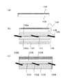
実施の形態1の製造プロセスとしては限定するものではないが例えば次に説明するような、工法が可能である。図2(a)から図2(c)は、実施の形態1の組立プロセスを表す各工程の断面図であり、まずはアルコキシシランからゾルを調整し、次にこれにフィラーを添加し分散させる。さらに蛍光体を添加して分散させ、ゾルゲル硬化体層の原液とする。
<Method for manufacturing solar cell>
Although it does not limit as a manufacturing process of Embodiment 1, the construction method which is demonstrated below, for example is possible. 2 (a) to 2 (c) are cross-sectional views of the steps representing the assembly process of the first embodiment. First, a sol is prepared from alkoxysilane, and then a filler is added and dispersed therein. Further, a phosphor is added and dispersed to obtain a stock solution of the sol-gel cured body layer.
具体的な製法を以下に述べる。 A specific production method is described below.
(1)ゾルの調製
アルコキシシランとしてフェニルトリメトキシシラン30gとジメチルジエトキシシラン17.2gと酢酸0.48g、および水41.2gの混合溶液を作製し、120℃で90分攪拌混合しゾルとした。この過程で水はアルコキシシランの加水分解に使用された後揮発する。
(1) Preparation of sol A mixed solution of 30 g of phenyltrimethoxysilane, 17.2 g of dimethyldiethoxysilane, 0.48 g of acetic acid, and 41.2 g of water as alkoxysilane was prepared and stirred and mixed at 120 ° C. for 90 minutes. did. In this process, water is volatilized after being used for hydrolysis of alkoxysilane.
(2)充填材の配合
充填材として平均粒径1μmであり屈折率が1.47の溶融球状シリカフィラーを使用した。シリカフィラー1.2gをキシレン75.1gに公知の方法により分散させ、分散液をゾル30gに添加し、室温で12時間放置した。
(2) Blending of filler A fused spherical silica filler having an average particle diameter of 1 μm and a refractive index of 1.47 was used as the filler. 1.2 g of silica filler was dispersed in 75.1 g of xylene by a known method, and the dispersion was added to 30 g of sol and left at room temperature for 12 hours.
(3)蛍光体のゾル溶液の調製
次に適当な蛍光体を適当な溶媒に溶解させた蛍光体溶液を作製し、前述のゾル溶液に添加する。蛍光体溶液を添加する際に、上記で配合した充填材が沈降している場合には、攪拌などを行い、再度分散させる。本実施形態では、Eu(3価)錯体である(1,10−Phenanthroline)tris[4,4,4−trifluoro−1−(2−thienyl)−1,3−butanedionato]europium(III)をジメチルホルムアミドに0.6重量%配合したものを、上記で調整した充填材を配合したゾル溶液に、12g添加した。
(3) Preparation of sol solution of phosphor Next, a phosphor solution in which an appropriate phosphor is dissolved in an appropriate solvent is prepared and added to the sol solution described above. When the phosphor solution is added, if the filler blended in the above is settled, stirring is performed and dispersed again. In this embodiment, (1,10-Phenanthroline) tris [4,4,4-trifluoro-1- (2-thienyl) -1,3-buteanionato] europium (III), which is an Eu (trivalent) complex, is converted to dimethyl 12 g of a formamide blended with 0.6 wt% was added to the sol solution blended with the filler prepared above.
(4)蛍光体含有のゾルゲル硬化体層106の形成
上記のシリカが配合された蛍光体のゾル溶液を太陽電池用の保護ガラス105にスピンコート塗布し、100℃で1時間加熱し、さらに120℃で5時間加熱し、図2(a)に示すようなゾルゲル重合体に蛍光体とフィラーを含有するゾルゲル硬化体層106が保護ガラス105の表面に配置された保護材料108を作製することができる。
(4) Formation of Phosphor-Containing Sol-Gel Cured Material Layer 106 A phosphor sol solution containing the above silica is spin-coated on a
このようにして得られたゾルゲル硬化体層106は、屈折率が1.47であり、ゾルゲル重合体中において、アルコキシシラン由来のシラノール基の脱水縮合によってシロキサン骨格が形成され、シリカが分散していることにより、収縮が抑制されクラックの発生がなく、且つ蛍光体が配合された構造となっている。
The sol-gel cured
次に、図2(b)において、保護材料108と、太陽電池モジュール100における光電変換素子101の表側に配置する透明樹脂102aと、裏側に配置する透明樹脂102bと、電極104が電気的に接合された光電変換素子101と、バックシート103と、をラミネート処理する。
Next, in FIG. 2B, the
このことにより、ゾルゲル硬化体層106により、蛍光体が保護され、蛍光体から発せられた蛍光が長寿命に効率よく光電変換素子101に到達し、さらに保護ガラス105よりも屈折率の低いゾルゲル硬化体層106が入射面に配置されていることによる、反射防止効果により発電効率の高い太陽電池モジュールとすることができる(図2(c))。
As a result, the phosphor is protected by the sol-gel cured
<効果、従来例との違い>
ゾルゲル硬化体層106は、シリカフィラーが充填されているため、ゾルゲル重合体の脱水縮合時の重合過程における収縮によるクラックが発生せず、また酸素や水蒸気が侵入しにくい。
<Effects and differences from conventional examples>
Since the sol-gel
結果として、ゾルゲル硬化体層106はガスバリア性の高い膜であり、従来使用することのできなかった昇華性の高い蛍光体や、酸素や水蒸気の侵入により劣化を免れなかった蛍光体を使用することができる。
As a result, the sol-gel
また以上の効果により硬化体層にエポキシ樹脂を使用した従来例よりもさらに蛍光体を長寿命に保護することができる。気温85℃、湿度85%での放置試験において従来例では、初期からの発光強度が90%以上維持される時間が500時間であるのに対し、本実施形態では1100時間発光が維持される。 Further, the phosphor can be protected with a longer life than the conventional example using an epoxy resin for the cured body layer due to the above effects. In the standing test at a temperature of 85 ° C. and a humidity of 85%, in the conventional example, the time during which the light emission intensity from the initial stage is maintained at 90% or more is 500 hours, whereas in this embodiment, the light emission is maintained for 1100 hours.
(実施の形態2)
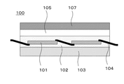
図3は、実施の形態2に係る太陽電池モジュール100の構造を示す断面図である。第1の実施形態と異なる点は、ゾルゲル重合体において、充填されるフィラーの表面が反応性有機官能基で修飾されている点と、ゾルゲル重合体の原料となるアルコキシシランのうち、少なくとも1種類にフィラーの表面を修飾している反応性有機官能基と反応する反応性有機官能基とが含まれている点とである。
(Embodiment 2)
FIG. 3 is a cross-sectional view showing the structure of
ここで、フィラーの表面が反応性有機官能基で修飾されるとは、フィラーの表面と反応性有機官能基とで化学結合していることを意味する。 Here, that the surface of the filler is modified with a reactive organic functional group means that the surface of the filler is chemically bonded to the reactive organic functional group.
さらに、ゾルゲル重合体に含まれる反応性有機官能基と、充填されるフィラーの表面を修飾している反応性有機官能基が反応により結合しており、その他は実施の形態1と同様である。 Furthermore, the reactive organic functional group contained in the sol-gel polymer and the reactive organic functional group that modifies the surface of the filler to be filled are bonded by reaction, and the others are the same as in the first embodiment.
実施の形態2の太陽電池モジュール100では、少なくとも光電変換素子101と、光電変換素子101を保護する透明樹脂102と、バックシート103と、光電変換素子同士を接続しかつ外部へ得られた電流を取り出す電極104と、保護ガラス105と、保護ガラス105上で、ゾルゲル重合体と蛍光体とフィラーとを含むゾルゲル硬化体層107と、を備えている。
In the
<太陽電池の製造方法>
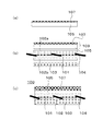
実施の形態2の製造プロセスとしては、限定するものではないが例えば次に説明するような工法が可能である。図4(a)から図4(d)は、実施の形態2の組立プロセスを表す各工程の断面図である。まずは、少なくとも1種類の反応性有機官能基を有するアルコキシシランからゾルを調整し、次にこれに反応性有機官能基で表面を修飾されたフィラーを充填分散する。さらに蛍光体を添加して分散させ、ゾルゲル硬化体層の原液とする。
<Method for manufacturing solar cell>
The manufacturing process of the second embodiment is not limited, but for example, a construction method as described below is possible. FIG. 4A to FIG. 4D are cross-sectional views of each process representing the assembly process of the second embodiment. First, a sol is prepared from an alkoxysilane having at least one type of reactive organic functional group, and then a filler whose surface is modified with a reactive organic functional group is filled and dispersed therein. Further, a phosphor is added and dispersed to obtain a stock solution of the sol-gel cured body layer.
ここで、ゾルゲル硬化体は、少なくとも1種類の反応性有機官能基を有する金属アルコキシドを原料に含む。 Here, the sol-gel hardened body contains a metal alkoxide having at least one kind of reactive organic functional group as a raw material.
反応性有機官能基としては限定するものではないが、たとえば、グリシドキシプロピル基や、スチリル基、アクリレート基、メチルメタクリレート基、ビニル基およびその誘導体、チオールプロピル基、アミノプロピル基とすることができ、光反応、熱反応あるいはそれらの組合せなど反応誘起方法を適宜選択することが出来る。 Although it does not limit as a reactive organic functional group, For example, it may be set as glycidoxypropyl group, styryl group, acrylate group, methyl methacrylate group, vinyl group and its derivative, thiolpropyl group, aminopropyl group. The reaction induction method such as photoreaction, thermal reaction, or a combination thereof can be appropriately selected.
また、これらの官能基の2種類以上を併用しても良い。特に、チオールプロピル基やアミノプロピル基は、グリシドキシプロピル基を重合させることができることから、グリシドキシプロピル基と好適に混合し用いることができる。 Two or more of these functional groups may be used in combination. In particular, a thiolpropyl group or an aminopropyl group can be used by being suitably mixed with a glycidoxypropyl group because a glycidoxypropyl group can be polymerized.
また、ゾルゲル重合体に使用する反応性有機官能基と、後述するフィラーの表面を修飾する反応性有機官能基の組合せとしては限定するものではなく、例えば上記の中で異なる組合せでも良いが、より効率よく反応するという観点から同じものとすることが好ましい。 Further, the combination of the reactive organic functional group used in the sol-gel polymer and the reactive organic functional group for modifying the surface of the filler described later is not limited, and for example, different combinations may be used in the above, It is preferable to make it the same from a viewpoint of reacting efficiently.
このような構成とすることにより、ゾルゲル重合体中に配合されたフィラーの表面は、化学結合により強固にゾルゲル重合体と密着することとなり、さらにクラックが起こりにくく、酸素や水といった大気中の低分子も透過しにくくなり、信頼性が高い高効率な太陽電池モジュールを形成できることになる。 By adopting such a configuration, the surface of the filler blended in the sol-gel polymer is firmly adhered to the sol-gel polymer by chemical bonding, and cracks are less likely to occur. It becomes difficult for molecules to penetrate, and a highly efficient solar cell module with high reliability can be formed.
具体的な製法を以下に、ゾルゲル硬化体の製法から順に述べる。 A specific production method will be described below in order from the production method of the sol-gel cured product.
(1)ゾルの調製
アルコキシシランとしてフェニルトリメトキシシラン12.0gとジメチルジエトキシシラン17.2gとグリシドキシプロピルトリメトキシシラン21.4gと酢酸0.48g、および水41.2gの混合溶液を作製し、120℃で90分攪拌混合しゾルとした。この過程で水はアルコキシシランの加水分解に使用された後揮発する。
(1) Preparation of sol A mixed solution of 12.0 g of phenyltrimethoxysilane, 17.2 g of dimethyldiethoxysilane, 21.4 g of glycidoxypropyltrimethoxysilane, 0.48 g of acetic acid and 41.2 g of water as alkoxysilane It was prepared and stirred for 90 minutes at 120 ° C. to obtain a sol. In this process, water is volatilized after being used for hydrolysis of alkoxysilane.
(2)充填材の表面修飾と配合
充填材として平均粒径1μmであり屈折率が1.47の溶融球状シリカフィラーを使用した。充填材の表面処理としては、次のように行った。シリカフィラー2.5gをアセトン29.55g中に添加し、さらに水0.05gとグリシドキシプロピルトリメトキシシラン0.27gを添加する。この配合液を密閉系において室温で8時間攪拌した。攪拌が終了した配合液を開放系において、100℃で1時間乾燥させ、残存したシリカフィラーを回収した。回収したシリカフィラーの表面は存在していたシラノール基がグリシドキシプロピル基に置換され、表面修飾されている。
(2) Surface modification and blending of filler A fused spherical silica filler having an average particle diameter of 1 μm and a refractive index of 1.47 was used as the filler. The surface treatment of the filler was performed as follows. 2.5 g of silica filler is added to 29.55 g of acetone, and 0.05 g of water and 0.27 g of glycidoxypropyltrimethoxysilane are added. This mixture was stirred for 8 hours at room temperature in a closed system. The mixed solution after the stirring was dried in an open system at 100 ° C. for 1 hour, and the remaining silica filler was recovered. The surface of the recovered silica filler is modified by replacing existing silanol groups with glycidoxypropyl groups.
このようにして表面修飾の完了したシリカフィラー1.2gをキシレン75.1gに公知の方法により分散させ、分散液を上記で調整したゾル30gに添加し、室温で12時間放置した。 Thus, 1.2 g of the silica filler whose surface modification was completed was dispersed in 75.1 g of xylene by a known method, and the dispersion was added to 30 g of the sol prepared as described above, and left at room temperature for 12 hours.
(3)蛍光体のゾル溶液の調製
次に適当な蛍光体を適当な溶媒に溶解させた蛍光体溶液を作製し、前述のゾル溶液に添加する。蛍光体溶液を添加する際に、上記で配合したシリカフィラーが沈降している場合には、攪拌などを行い、再度分散させる。本実施形態では、Eu(3価)錯体である(1,10−Phenanthroline)tris[4,4,4−trifluoro−1−(2−thienyl)−1,3−butanedionato]europium(III)をジメチルホルムアミドに0.6重量%配合したものを、上記で調整した充填材を配合したゾル溶液に、12g添加した。
(3) Preparation of sol solution of phosphor Next, a phosphor solution in which an appropriate phosphor is dissolved in an appropriate solvent is prepared and added to the sol solution described above. When adding the phosphor solution, if the silica filler compounded above is settled, it is stirred again and dispersed again. In this embodiment, (1,10-Phenanthroline) tris [4,4,4-trifluoro-1- (2-thienyl) -1,3-buteanionato] europium (III), which is an Eu (trivalent) complex, is converted to dimethyl 12 g of a formamide blended with 0.6 wt% was added to the sol solution blended with the filler prepared above.
(4)蛍光体含有ゾルゲル硬化体層の形成
図4(a)から図4(d)の断面図を用いて、実施の形態2の組立プロセスを説明する。
(4) Formation of Phosphor-Containing Sol-Gel Cured Body Layer The assembly process of Embodiment 2 will be described using the cross-sectional views of FIGS. 4 (a) to 4 (d).
上記のシリカフィラーおよび蛍光体を含有したゾル溶液を太陽電池用の保護ガラス105にスピンコート塗布し、100℃で1時間加熱し、さらに120℃で5時間加熱し、図4(a)に示すような蛍光体を含有するゾルゲル硬化体層107が保護ガラス105の表面に配置された保護材料109を作製することができる。
The sol solution containing the silica filler and the phosphor is spin-coated on the
このようにして得られたゾルゲル硬化体層107は、屈折率が1.47である。ゾルゲル重合体中において、アルコキシシラン由来のシラノール基の脱水縮合によってシロキサン骨格が形成される。シリカが分散しており、さらにシリカフィラーの表面を修飾しているグリシドキシ基と、ゾルゲル重合体中に含まれるグリシドキシプロピルトリメトキシシラン由来のグリシドキシ基とが、反応することにより、シリカフィラーは、さらに強固にゾルゲル重合体中に担持される。結果、収縮が抑制されクラックの発生がなく、且つ蛍光体が配合された構造となっている。
The sol-gel cured
次に、図4(b)において、保護材料109と、太陽電池における光電変換素子101の表側に配置する透明樹脂102aと、裏側に配置する透明樹脂102bと、電極104が電気的に接合された光電変換素子101と、バックシート103とを、ラミネート処理する。
Next, in FIG. 4B, the
このことにより、シリカフィラーが配合されたゾルゲル硬化体層107により、透明材料中に含有された蛍光体が保護される。蛍光体から発せられた蛍光が長寿命に効率よく光電変換素子101に到達する。
As a result, the phosphor contained in the transparent material is protected by the sol-gel hardened
さらに保護ガラス105よりも屈折率の低いゾルゲル硬化体層107が入射面に配置されていることによる、反射防止効果が生じる。これより発電効率の高い太陽電池モジュール100とすることができる。(図4(c))。
Further, an antireflection effect is produced by the sol-gel hardened
また、ゾルゲル硬化体層107は、原料であるアルコキシシランに含まれるグシリドキシ基と、シリカフィラー表面を修飾したグリシドキシ基とが、反応している。このため、シリカフィラーとゾルゲル重合体がより強固に密着している。
In the sol-gel
その結果として、ゾルゲル硬化体層107は、ガスバリア性の高い膜であり、従来使用することのできなかった昇華性の高い蛍光体や、酸素や水蒸気の侵入により劣化を免れなかった蛍光体をゾルゲル硬化体層107中に含有させることができる。
As a result, the sol-gel
<効果>
実施の形態1ではゾルゲル硬化体層107中にフィラーが配合され、フィラー表面とゾルゲル硬化体は物理的に密着している。しかし、実施の形態2では、フィラーの表面とゾルゲル硬化体層107は、化学的に密着しているため、ガスバリア性が、さらに高く、実施の形態1よりも、さらに蛍光体を長寿命に保護することができる。
<Effect>
In the first embodiment, a filler is blended in the sol-gel cured
気温85℃、湿度85%での放置試験において、ゾルゲル硬化体層107に、エポキシ樹脂を使用した従来例では、初期からの発光強度が90%以上維持される時間が、従来例では500時間であった。それに対して、実施の形態1では、1100時間、実施の形態2では、1300時間、発光が維持される。
In the conventional example in which an epoxy resin is used for the sol-gel cured
以上説明したように、本発明の太陽電池モジュールは、従来よりも高効率な太陽電池として広く使用される。 As described above, the solar cell module of the present invention is widely used as a solar cell with higher efficiency than before.
11 透明樹脂
12 波長変換層
100 太陽電池モジュール
101 光電変換素子
102 透明樹脂
102a 透明樹脂
102b 透明樹脂
103 バックシート
104 電極
105 保護ガラス
106 ゾルゲル硬化体層
107 ゾルゲル硬化体層
108 保護材料
109 保護材料
DESCRIPTION OF
Claims (5)
前記光電変換素子と電気的に接続された電極と、
前記光電変換素子と前記電極とを内部に含む第一の透明樹脂と、
前記第一の透明樹脂の下部に配置されたバックシートと、
前記第一の透明樹脂の上部に配置された保護ガラスと、
前記保護ガラスに配置され、蛍光体を含有するゾルゲル硬化体層と、
を備えた太陽電池モジュールであって、
前記ゾルゲル硬化体層の中に、無機充填材が配合されていることを特徴とする太陽電池モジュール。 A photoelectric conversion element;
An electrode electrically connected to the photoelectric conversion element;
A first transparent resin containing the photoelectric conversion element and the electrode inside;
A back sheet disposed under the first transparent resin;
A protective glass disposed on top of the first transparent resin;
A sol-gel hardened body layer that is disposed on the protective glass and contains a phosphor, and
A solar cell module comprising:
An inorganic filler is blended in the sol-gel hardened body layer.
前記ゾルゲル硬化体層が第2反応性有機官能基を有し、
前記第1反応性有機官能基と前記第2反応性有機官能基とが結合している請求項1および2記載の太陽電池モジュール。 The surface of the inorganic filler is modified with a first reactive organic functional group;
The sol-gel cured body layer has a second reactive organic functional group,
The solar cell module according to claim 1 or 2, wherein the first reactive organic functional group and the second reactive organic functional group are bonded.
5. The solar cell module according to claim 1, wherein the phosphor is one of an inorganic phosphor, an organic phosphor, a complex phosphor, or a combination thereof.
Priority Applications (1)
| Application Number | Priority Date | Filing Date | Title |
|---|---|---|---|
| JP2014086988A JP2015207648A (en) | 2014-04-21 | 2014-04-21 | Solar cell module |
Applications Claiming Priority (1)
| Application Number | Priority Date | Filing Date | Title |
|---|---|---|---|
| JP2014086988A JP2015207648A (en) | 2014-04-21 | 2014-04-21 | Solar cell module |
Publications (1)
| Publication Number | Publication Date |
|---|---|
| JP2015207648A true JP2015207648A (en) | 2015-11-19 |
Family
ID=54604240
Family Applications (1)
| Application Number | Title | Priority Date | Filing Date |
|---|---|---|---|
| JP2014086988A Pending JP2015207648A (en) | 2014-04-21 | 2014-04-21 | Solar cell module |
Country Status (1)
| Country | Link |
|---|---|
| JP (1) | JP2015207648A (en) |
Cited By (2)
| Publication number | Priority date | Publication date | Assignee | Title |
|---|---|---|---|---|
| JP2015212360A (en) * | 2014-04-17 | 2015-11-26 | パナソニックIpマネジメント株式会社 | Resin composition, method for producing the same, and semiconductor device |
| JP2020012041A (en) * | 2018-07-17 | 2020-01-23 | パナソニックIpマネジメント株式会社 | Coating composition for gas barrier and light emitting device |
-
2014
- 2014-04-21 JP JP2014086988A patent/JP2015207648A/en active Pending
Cited By (2)
| Publication number | Priority date | Publication date | Assignee | Title |
|---|---|---|---|---|
| JP2015212360A (en) * | 2014-04-17 | 2015-11-26 | パナソニックIpマネジメント株式会社 | Resin composition, method for producing the same, and semiconductor device |
| JP2020012041A (en) * | 2018-07-17 | 2020-01-23 | パナソニックIpマネジメント株式会社 | Coating composition for gas barrier and light emitting device |
Similar Documents
| Publication | Publication Date | Title |
|---|---|---|
| Liu et al. | Molecular core–shell structure design: Facilitating delayed fluorescence in aggregates toward highly efficient solution‐processed OLEDs | |
| Wang et al. | Perovskite quantum dots and their application in light‐emitting diodes | |
| Yoon et al. | Efficient and stable CsPbBr3 quantum-dot powders passivated and encapsulated with a mixed silicon nitride and silicon oxide inorganic polymer matrix | |
| Datt et al. | Down‐conversion materials for organic solar cells: Progress, challenges, and perspectives: Photovoltaics: Special Issue Dedicated to Professor Yongfang Li | |
| CN106010518B (en) | A kind of Copper-cladding Aluminum Bar full-inorganic halogen perovskite fluorescent material and preparation method and purposes | |
| Zhang et al. | Thermally stable white emitting Eu3+ complex@ nanozeolite@ luminescent glass composite with high CRI for organic-resin-free warm white LEDs | |
| CN106098952B (en) | Organosilicon functionalized red-light carbon quantum dot and preparation method and application thereof | |
| CN106867528A (en) | A kind of carbon nano dot and preparation method thereof, carbon nano dot composite and preparation method thereof and emitting led | |
| CN117247362B (en) | Asymmetric structure light conversion agent, light conversion film and preparation method thereof | |
| Liu et al. | Crystal structure and photoluminescence properties of red‐emitting Ca9La1− x (VO4) 7: xEu3+ phosphors for white light‐emitting diodes | |
| CN111295929A (en) | Drying agent, organic thin film containing same, organic laminated film having organic thin film laminated thereon, and electronic device having same | |
| Dai et al. | Tuning solar absorption spectra via carbon quantum dots/VAE composite layer and efficiency enhancement for crystalline Si solar module | |
| CN111373840A (en) | Manufacturing method of electronic device | |
| Xue et al. | Ce3+/Tb3+‐coactived NaMgBO3 phosphors toward versatile applications in white LED, FED, and optical anti‐counterfeiting | |
| Lv et al. | Carbon quantum dots anchored on the anti-reflection silica layer as solid luminescence down-shifting materials in solar panel encapsulation | |
| Khursheed et al. | Optical properties of Sr3B2O6: Dy3+/PMMA polymer nanocomposites | |
| Xu et al. | Highly efficient silica coated perovskite nanocrystals with the assistance of ionic liquids for warm white LEDs | |
| CN107437571A (en) | Solar module and its manufacture method | |
| Sekar et al. | BCNO silica gel-based green transparent and efficient luminescent downshifting layer for Si solar cells | |
| CN113480493B (en) | Organic yellow fluorescence excited proton transfer material and OLED device thereof | |
| CN102891203A (en) | Fluorescence conversion white packaging material and solar cell adopting same | |
| RU2655358C2 (en) | Optical composition | |
| JP2015207648A (en) | Solar cell module | |
| CN114335353A (en) | Solar spectrum wavelength conversion material and solar cell comprising same | |
| CN109256494A (en) | SrCl2Perovskite quantum dot High Efficiency Luminescence LED of doping and preparation method thereof |
Legal Events
| Date | Code | Title | Description |
|---|---|---|---|
| RD01 | Notification of change of attorney |
Free format text: JAPANESE INTERMEDIATE CODE: A7421 Effective date: 20160520 |