JP2015204657A - Vehicular discharge device - Google Patents
Vehicular discharge device Download PDFInfo
- Publication number
- JP2015204657A JP2015204657A JP2014081826A JP2014081826A JP2015204657A JP 2015204657 A JP2015204657 A JP 2015204657A JP 2014081826 A JP2014081826 A JP 2014081826A JP 2014081826 A JP2014081826 A JP 2014081826A JP 2015204657 A JP2015204657 A JP 2015204657A
- Authority
- JP
- Japan
- Prior art keywords
- switch
- vehicle
- voltage
- switches
- insulation resistance
- Prior art date
- Legal status (The legal status is an assumption and is not a legal conclusion. Google has not performed a legal analysis and makes no representation as to the accuracy of the status listed.)
- Pending
Links
Images


Landscapes
- Electric Propulsion And Braking For Vehicles (AREA)
- Dc-Dc Converters (AREA)
- Inverter Devices (AREA)
Abstract
Description
本発明は、車両用放電装置に関し、詳しくは、モータからの動力で走行する車両に搭載された電気回路内の平滑コンデンサを放電させるための車両用放電装置に関する。 The present invention relates to a vehicular discharge device, and more particularly to a vehicular discharge device for discharging a smoothing capacitor in an electric circuit mounted on a vehicle traveling with power from a motor.
従来、この種の車両用放電装置としては、車載された高電圧バッテリからの直流電力を平滑する平滑コンデンサと、高電圧バッテリの正極端と平滑コンデンサの一端との間に設けられた第1リレーと、高電圧バッテリの負極端と平滑コンデンサの他端との間に設けられた第2リレーと、電圧駆動型の2つのIGBTを有する3つのスイッチング回路が搭載され高電圧バッテリからの直流電圧を三相交流電圧に変換するインバータ回路と、を備えるものが提案されている(例えば、特許文献1参照)。この装置では、イグニッションオフ時には、第1リレーおよび第2リレーをオフし、2つのIGBTのうちの一方にはフルオンするのに十分な電圧をゲート端子に印加させて電流制限せずにオンさせ、他方にはフルオンする電圧より低く制限された電圧をゲート端子に印加して電流制限をしてオンさせ、その後、電流制限するIGBTを、それまで電流制限していなかったIGBTに切り替える。これにより、一方のIGBTのみに大きい電流が流れてIGBTが許容範囲を超えて発熱することを抑制しながら平滑コンデンサを放電している。 Conventionally, as this type of vehicle discharge device, a smoothing capacitor that smoothes DC power from a high-voltage battery mounted on a vehicle, and a first relay provided between a positive terminal of the high-voltage battery and one end of the smoothing capacitor And a second relay provided between the negative electrode end of the high-voltage battery and the other end of the smoothing capacitor, and three switching circuits having two voltage-driven IGBTs are mounted, and the DC voltage from the high-voltage battery is The thing provided with the inverter circuit converted into a three-phase alternating voltage is proposed (for example, refer patent document 1). In this device, when the ignition is turned off, the first relay and the second relay are turned off, and a voltage sufficient to fully turn on one of the two IGBTs is applied to the gate terminal to turn it on without current limitation. On the other hand, a voltage limited to a voltage lower than the full-on voltage is applied to the gate terminal to limit the current to ON, and thereafter, the IGBT whose current is limited is switched to the IGBT that has not been current limited until then. As a result, the smoothing capacitor is discharged while suppressing a large current flowing only in one of the IGBTs and causing the IGBT to generate heat exceeding the allowable range.
ところで、車両に搭載された電気回路内の平滑コンデンサを放電するために、平滑コンデンサに並列にスイッチが接続されてなる車両用放電装置では、スイッチの故障や異常により車両が走行できなくなることは好ましくないため、故障や異常が生じたときでも走行を継続できるようにすることが望まれている。また、ユーザがこうした異常を認識できずにそのまま走行を継続することも好ましくないため、異常が生じていることをユーザが認識できるようにすることが望まれている。 By the way, in the vehicle discharge device in which the switch is connected in parallel to the smoothing capacitor in order to discharge the smoothing capacitor in the electric circuit mounted on the vehicle, it is preferable that the vehicle cannot run due to a failure or abnormality of the switch. Therefore, it is desired to continue running even when a failure or abnormality occurs. In addition, it is not preferable for the user to continue traveling without being able to recognize such an abnormality, so it is desired that the user can recognize that an abnormality has occurred.
本発明の車両用放電装置は、異常が生じたときに車両が走行不能になることを抑制すると共に異常が生じていることをユーザに認識させることを主目的とする。 The main purpose of the vehicular discharge device of the present invention is to prevent the vehicle from being unable to travel when an abnormality occurs and to make the user recognize that the abnormality has occurred.
本発明の車両用放電装置は、上述の主目的を達成するために以下の手段を採った。 The vehicle discharge device of the present invention employs the following means in order to achieve the main object described above.
本発明の車両用放電装置は、
モータからの動力で走行する車両に搭載された電気回路内の平滑コンデンサを放電させるための車両用放電装置であって、
直列接続された2つのスイッチを有し、前記平滑コンデンサに並列に接続されると共に前記2つのスイッチの接続点が前記車両の車体に接続されたスイッチ回路と、
前記2つのスイッチのうちの少なくとも一方と前記車体との間の絶縁抵抗の低下を判定する絶縁状態判定手段と、
前記絶縁状態判定手段により前記2つのスイッチのうちの一方と前記車体との間の絶縁抵抗が低下していると判定されたときに、異常を報知する異常報知手段と、
を備えることを要旨とする。
The vehicle discharge device of the present invention comprises:
A discharge device for a vehicle for discharging a smoothing capacitor in an electric circuit mounted on a vehicle traveling with power from a motor,
A switch circuit having two switches connected in series, connected in parallel to the smoothing capacitor, and having a connection point of the two switches connected to a vehicle body of the vehicle;
Insulation state determination means for determining a decrease in insulation resistance between at least one of the two switches and the vehicle body;
An abnormality notifying means for notifying an abnormality when it is determined by the insulation state determining means that an insulation resistance between one of the two switches and the vehicle body is reduced;
It is a summary to provide.
この本発明の車両用放電装置では、直列接続された2つのスイッチを有するスイッチ回路を平滑コンデンサに並列に接続すると共にスイッチ回路の2つのスイッチの接続点を車両の車体に接続する。2つのスイッチが共に正常であるときには、2つのスイッチを共にオフすることで車両を走行させることができ、2つのスイッチを共にオンすることで平滑コンデンサを放電させることができる。また、2つスイッチの一方がオン固定となる異常が生じたときには、他方のスイッチにより、車両が走行不能になることを抑制することができる。そして、2つのスイッチのうちの少なくとも一方と車体との絶縁抵抗の低下を判定する絶縁状態判定手段を設け、絶縁状態判定手段により2つのスイッチのうちの一方と車体との間の絶縁抵抗が低下していると判定されたときに、異常を報知する。これにより、ユーザに異常が生じていることを認識させることができる。この結果、異常が生じたときに車両が走行不能になることを抑制すると共にユーザに異常が生じていることを認識させることができる。 In the vehicle discharge device of the present invention, a switch circuit having two switches connected in series is connected in parallel to a smoothing capacitor, and a connection point of the two switches of the switch circuit is connected to the vehicle body of the vehicle. When both the switches are normal, the vehicle can be driven by turning off the two switches, and the smoothing capacitor can be discharged by turning on the two switches together. Further, when an abnormality occurs in which one of the two switches is fixed to be on, the other switch can suppress the vehicle from being disabled. Insulation state determination means for determining a decrease in insulation resistance between at least one of the two switches and the vehicle body is provided, and the insulation resistance between one of the two switches and the vehicle body is reduced by the insulation state determination means. When it is determined that it is in progress, an abnormality is notified. As a result, the user can recognize that an abnormality has occurred. As a result, it is possible to prevent the vehicle from being unable to run when an abnormality occurs, and to make the user recognize that an abnormality has occurred.
次に、本発明を実施するための形態を実施例を用いて説明する。 Next, the form for implementing this invention is demonstrated using an Example.
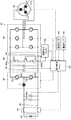
図1は、本発明の一実施例としての車両用放電装置を備える駆動装置20の構成の概略を示す構成図である。実施例の駆動装置20は、電気自動車やハイブリッド自動車,燃料電池自動車などに搭載され、図示するように、例えば同期発電電動機として構成された走行用のモータ32と、複数のスイッチング素子(トランジスタ)を有しモータ32を駆動するためのインバータ34と、例えばリチウムイオン二次電池として構成されたバッテリ36と、インバータ34が接続された電力ライン(以下、高圧側電力ラインという)42とバッテリ36が接続された電力ライン(以下、低圧側電力ラインという)44とに接続されて高圧側電力ライン42の電圧VHを調節すると共に高圧側電力ライン42と低圧側電力ライン44との間で電力のやりとりを行なう昇圧コンバータ40と、高圧側電力ライン42に取り付けられてこの電力ラインの電圧を平滑する高圧側コンデンサ46と、高圧側コンデンサ46に並列に接続されたスイッチ回路49と、低圧側電力ライン44に設けられたシステムメインリレー45と、低圧側電力ライン44におけるシステムメインリレー45より昇圧コンバータ40側に取り付けられてこの電力ラインの電圧を平滑する低圧側コンデンサ48と、スイッチ回路49と車体との絶縁状態を検出する絶縁抵抗モニタ52と、装置全体をコントロールする電子制御ユニット50と、を備える。なお、実施例の車両用放電装置としては、スイッチ回路49と、絶縁抵抗モニタ52と、電子制御ユニット50とが該当する。
FIG. 1 is a configuration diagram showing an outline of a configuration of a
昇圧コンバータ40は、2つのスイッチング素子としてのトランジスタT31,T32とトランジスタT31,T32に逆方向に並列接続された2つのダイオードD31,D32とリアクトルLとからなるコンバータとして構成されている。2つのトランジスタT31,T32は、高圧側電力ライン42の正極母線と高圧側電力ライン42および低圧側電力ライン44の負極母線との間で直列配置(直列接続)されている。また、リアクトルLは、トランジスタT31,T32の中間点(接続点)と低圧側電力ライン44の正極母線とに接続されている。したがって、トランジスタT31,T32をオンオフ制御することにより、低圧側電力ライン44の電力を昇圧して高圧側電力ライン42に供給したり、高圧側電力ライン42の電力を降圧して低圧側電力ライン44に供給したりすることができる。
スイッチ回路49は、直列接続されたスイッチSW1,SW2を備え、スイッチSW1,SW2の接続点は車体に接続されており、スイッチSW1のスイッチSW2と接続されていないほうの一端は高圧側電力ライン42の正極ラインに接続されており、スイッチSW2のスイッチSW1と接続されていないほうの一端は高圧側電力ライン42の負極ラインに接続されている。
The
絶縁抵抗モニタ52は、スイッチSW2と高圧側電力ライン42の負極ラインとの接続点Cnに接続され、一定周波数のパルス(例えば、矩形波や正弦波,三角波など)を発生する発振器と、発振器に接続された検出抵抗と、スイッチSW2と高圧側電力ライン42の負極ラインとの接続点Cnと検出抵抗とに接続されたコンデンサと、検出抵抗とコンデンサとの接続点に接続され高周波成分を除去するローパスフィルタとを備え、車体と接続点Cnとの間の絶縁抵抗の抵抗値と検出抵抗の抵抗値との割合に応じた電圧波形を電子制御ユニット50に出力する。
The
電子制御ユニット50は、図示しないが、CPUを中心とするマイクロプロセッサとして構成されており、CPUの他に、処理プログラムを記憶するROMやデータを一時的に記憶するRAM,入出力ポートを備える。電子制御ユニット50には、モータ32の回転子の回転位置を検出する回転位置検出センサ32aからのモータ32の回転子の回転位置θm,モータ32とインバータ34との接続ライン(電力ライン)に取り付けられた電流センサからの相電流Iu,Iv,Iw,バッテリ36の端子間に取り付けられた電圧センサからの端子間電圧Vb,バッテリ36の出力端子に取り付けられた電流センサからの充放電電流Ib,バッテリ36に取り付けられた温度センサからの電池温度Tb,高圧側コンデンサ46の端子間に取り付けられた電圧センサ46aからの高圧側コンデンサ46の電圧(高圧側電力ライン42の電圧)VH,低圧側コンデンサ48の端子間に取り付けられた電圧センサ48aからの低圧側コンデンサ48の電圧(低圧側電力ライン44の電圧)VL,車両の衝突を検出する衝突センサ54からの信号,その他、車両の駆動制御に必要な信号、例えば、イグニッションスイッチ(スタートスイッチ)からのイグニッション信号,シフトレバーの操作位置を検出するシフトポジションセンサからのシフトポジション,アクセルペダルの踏み込み量を検出するアクセルペダルポジションセンサからのアクセル開度,ブレーキペダルの踏み込み量を検出するブレーキペダルポジションセンサからのブレーキペダルポジション,車速センサからの車速などが入力ポートを介して入力されている。なお、衝突センサ54は、車両の加速度が衝突判定用の閾値を超えたときなどに車両の衝突を判定する。電子制御ユニット50からは、インバータ34のスイッチング素子(トランジスタ)へのスイッチング制御信号や昇圧コンバータ40のトランジスタT31,T32へのスイッチング制御信号,システムメインリレー45へのオンオフ信号,スイッチSW1,SW2へのオンオフ信号,メーター内の警告ランプ56を点灯するための点灯指示信号などが出力ポートを介して出力されている。なお、電子制御ユニット50は、回転位置検出センサ32aにより検出されたモータ32の回転子の回転位置θmに基づいてモータ32の回転子の電気角θeや回転数Nmを演算したり、電流センサにより検出されたバッテリ36の充放電電流Ibに基づいてそのときのバッテリ36から放電可能な電力量の全容量に対する割合である蓄電割合SOCを演算したり、演算した蓄電割合SOCと温度センサからの電池温度Tbとに基づいてバッテリ36を充放電してもよい最大許容電力である入出力制限Win,Woutを演算したりしている。
Although not shown, the
こうして構成された実施例の駆動装置20では、電子制御ユニット50は、通常時は、システムメインリレー45をオンとすると共にスイッチ回路49のスイッチSW1,SW2をオフした状態で、バッテリ36の入出力制限Win,Woutの範囲内でモータ32から出力すべきトルクとしてのトルク指令Tm*を設定すると共に設定したトルク指令Tm*でモータ32が駆動されるようインバータ34のスイッチング素子(トランジスタ)をスイッチング制御すると共に、高圧側電力ライン42の電圧VHがモータ32のトルク指令Tm*と回転数Nmとに応じた目標電圧VHtagとなるよう昇圧コンバータ40のトランジスタT31,T32をスイッチング制御する。
In the
また、電子制御ユニット50では、絶縁抵抗モニタ52の発振器からの電圧波形のピーク値と絶縁抵抗モニタ52からの電圧波形のピーク値とを比較することにより接続点Cnに対して印加する電圧と作用した電圧との電圧差(以下、接続点電圧差という)を計算し、接続点電圧差が所定の正常範囲内のときには電気系絶縁抵抗が正常であり低下していないと判定すると共に接続点電圧差が所定の正常範囲外のときには絶縁抵抗が異常であり低下していると判定する。
Further, the
次に、こうして構成された実施例の駆動装置20の動作、特に、衝突センサ54により車両の衝突が検出されたときの動作と、スイッチ回路49のスイッチSW2に異常が生じたときの動作とについて説明する。最初に衝突センサ54により車両の衝突が検出されたときの動作を説明する。
Next, the operation of the driving
衝突センサ54により車両の衝突が検出されると、電子制御ユニット50は、システムメインリレー45をオフとすると共にスイッチ回路49のスイッチSW1,SW2をオンし、昇圧コンバータ40のトランジスタT31,T32およびインバータ34の各スイッチング素子(トランジスタ)をゲート遮断する(ゲートをオフ固定にする)処理を実行する。こうした処理により、図2の太線矢印に示すように、高圧側コンデンサ46の両端がスイッチ回路49により短絡して、高圧側コンデンサ46が放電する。こうした放電により高圧側コンデンサ46の電圧,つまり、高圧側電力ライン42の電圧を比較的迅速に低下させることができる。
When a collision of the vehicle is detected by the collision sensor 54, the
次に、スイッチ回路49のスイッチSW2に異常が生じたときの動作について説明する。図3は、走行中、すなわち、システムメインリレー45がオンのときに、スイッチ回路49のスイッチSW2が何らかの異常でオン固定になったときの様子を示す説明図であり、図4は、スイッチ回路49が1個のスイッチSWを有する比較例の駆動装置においてスイッチSWがオン固定となる異常が生じたときの様子を示す説明図である。なお、実施例では、スイッチ回路49のスイッチSW1は正常に機能し、走行中はオフされているものとする。比較例では、スイッチSWがオン固定になると高圧側電力ライン42の正極側ラインと負極側ラインとが短絡してしまい、モータ32を駆動できなくなり車両の走行を継続することが困難になる。実施例では、走行中にスイッチ回路49のスイッチSW2がオン固定になっても、スイッチSW1が正常でオフしているから高圧側電力ライン42の正極側ラインと負極側ラインとが短絡することがなく、モータ32の駆動を継続して車両の走行を継続することができる。
Next, an operation when an abnormality occurs in the switch SW2 of the
また、スイッチSW2がオン固定する異常が発生すると、スイッチSW1,SW2の接続点が車体に接続されているから、絶縁抵抗モニタ52からの電圧波形のピーク値が変化して接続点電圧差が所定の正常範囲外となる。接続点電圧差が所定の正常範囲外となると、電子制御ユニット50は、絶縁抵抗が低下していると判定し、警告ランプ56に点灯指示信号を出力して、警告ランプ56を点灯させる。これにより、ユーザにスイッチ回路49に異常が生じたことを報知することができ、ユーザに何らかの対処、例えば、修理などを促すことができる。
Further, when an abnormality occurs in which the switch SW2 is fixed on, the connection point of the switches SW1 and SW2 is connected to the vehicle body, so that the peak value of the voltage waveform from the insulation resistance monitor 52 changes and the connection point voltage difference is predetermined. Outside the normal range. When the connection point voltage difference is outside the predetermined normal range, the
以上説明した実施例の駆動装置20によれば、スイッチ回路49が高圧側コンデンサ46に並列に接続されると共にスイッチSW1,SW2の接続点が車両の車体に接続されているから、スイッチSW2がオン固定となる異常が生じたときでも、車両が走行不能になることを抑制することができる。また、スイッチSW2と車体との絶縁状態を判定する絶縁抵抗モニタ52を設け、スイッチSW2と車体との間の絶縁抵抗が低下していると判定されたときに、警告ランプ56を点灯させることにより、ユーザに異常が生じていることを認識させることができる。
According to the driving
実施例の駆動装置20では、絶縁抵抗モニタ52をスイッチSW2と高圧側電力ライン42の負極ラインとの接続点Cnに接続するものとしたが、絶縁抵抗モニタ52をスイッチSW1と高圧側電力ライン42の正極ラインとの接続点に接続するものとしてもよい。こうすれば、スイッチSW1と車体との間の絶縁抵抗の低下の有無を判定することができる。また、2つの絶縁抵抗モニタを用意し、スイッチSW2と高圧側電力ライン42の負極ラインとの接続点CnおよびスイッチSW1と高圧側電力ライン42の正極ラインとの接続点の2カ所にそれぞれの絶縁抵抗モニタを接続するものとしてもよい。こうすれば、スイッチSW1,SW2の双方と車体との間の絶縁抵抗の低下の有無を判定することができる。
In the driving
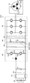
実施例の駆動装置20では、スイッチ回路49を直列接続された2つのスイッチSW1,SW2を備えているものとしたが、図5の変形例の駆動装置120に例示するように、スイッチSW1と高圧側電力ライン42の正極ラインとの間に抵抗R100が接続されているものとしたり、図6の変形例の駆動装置220に例示するようにスイッチSW2と高圧側電力ライン42の負極ラインとの間に抵抗R200が接続されているものとしたり、図7の変形例の駆動装置320に例示するように、スイッチSW1,SW2との間に抵抗R300が接続されているものとしてもよい。こうすれば、衝突時にスイッチSW1,SW2がオンされたときでも、抵抗R100,R200,R300により、スイッチSW1,SW2や高圧側コンデンサ46に流れる電流(短絡電流)をより低くすることができ、スイッチSW1,SW2や高圧側コンデンサ46の保護を図ることができる。
In the driving
実施例では、昇圧コンバータ40を備えるタイプの駆動装置に適用する場合を例示したが、昇圧コンバータ40と低圧側コンデンサ48とを備えずにバッテリからの電力を昇圧せずにインバータに供給してモータを駆動するタイプの駆動装置に適用するものとしてもよい。
In the embodiment, the case where the present invention is applied to the type of drive device including the
実施例の主要な要素と課題を解決するための手段の欄に記載した発明の主要な要素との対応関係について説明する。実施例では、高圧側コンデンサ46が「平滑コンデンサ」に相当し、スイッチ回路49が「スイッチ回路」に相当し、絶縁抵抗モニタ52と電子制御ユニット50とを組み合わせたものが「絶縁状態判定手段」に相当し、電子制御ユニット50と警告ランプ56とを組み合わせたものが「異常報知手段」に相当する。
The correspondence between the main elements of the embodiment and the main elements of the invention described in the column of means for solving the problems will be described. In the embodiment, the high
なお、実施例の主要な要素と課題を解決するための手段の欄に記載した発明の主要な要素との対応関係は、実施例が課題を解決するための手段の欄に記載した発明を実施するための形態を具体的に説明するための一例であることから、課題を解決するための手段の欄に記載した発明の要素を限定するものではない。即ち、課題を解決するための手段の欄に記載した発明についての解釈はその欄の記載に基づいて行なわれるべきものであり、実施例は課題を解決するための手段の欄に記載した発明の具体的な一例に過ぎないものである。 The correspondence between the main elements of the embodiment and the main elements of the invention described in the column of means for solving the problem is the same as that of the embodiment described in the column of means for solving the problem. Therefore, the elements of the invention described in the column of means for solving the problems are not limited. That is, the interpretation of the invention described in the column of means for solving the problems should be made based on the description of the column, and the examples are those of the invention described in the column of means for solving the problems. It is only a specific example.
以上、本発明を実施するための形態について実施例を用いて説明したが、本発明はこうした実施例に何等限定されるものではなく、本発明の要旨を逸脱しない範囲内において、種々なる形態で実施し得ることは勿論である。 As mentioned above, although the form for implementing this invention was demonstrated using the Example, this invention is not limited at all to such an Example, In the range which does not deviate from the summary of this invention, it is with various forms. Of course, it can be implemented.
本発明は、車両用放電装置の製造産業などに利用可能である。 The present invention can be used in the manufacturing industry of vehicle discharge devices.
20,120,220,320 駆動装置、32 モータ、32a 回転位置検出センサ、34 インバータ、36 バッテリ、40 昇圧コンバータ、42 高圧側電力ライン、44 低圧側電力ライン、45 システムメインリレー、46 高圧側コンデンサ、46a,48a 電圧センサ、48 低圧側コンデンサ、49 スイッチ回路、50 電子制御ユニット、52 絶縁抵抗モニタ、54 衝突センサ、56 警告ランプ、D31,D32 ダイオード、L リアクトル、R100,R200,R300 抵抗、SW,SW1,SW2 スイッチ、T31,T32 トランジスタ。 20, 120, 220, 320 Drive device, 32 motor, 32a rotational position detection sensor, 34 inverter, 36 battery, 40 boost converter, 42 high voltage side power line, 44 low voltage side power line, 45 system main relay, 46 high voltage side capacitor , 46a, 48a Voltage sensor, 48 Low voltage side capacitor, 49 Switch circuit, 50 Electronic control unit, 52 Insulation resistance monitor, 54 Collision sensor, 56 Warning lamp, D31, D32 diode, L reactor, R100, R200, R300 Resistance, SW , SW1, SW2 switches, T31, T32 transistors.
Claims (1)
直列接続された2つのスイッチを有し、前記平滑コンデンサに並列に接続されると共に前記2つのスイッチの接続点が前記車両の車体に接続されたスイッチ回路と、
前記2つのスイッチのうちの少なくとも一方と前記車体との間の絶縁抵抗の低下を判定する絶縁状態判定手段と、
前記絶縁状態判定手段により前記2つのスイッチのうちの一方と前記車体との間の絶縁抵抗が低下していると判定されたときに、異常を報知する異常報知手段と、
を備える車両用放電装置。 A discharge device for a vehicle for discharging a smoothing capacitor in an electric circuit mounted on a vehicle traveling with power from a motor,
A switch circuit having two switches connected in series, connected in parallel to the smoothing capacitor, and having a connection point of the two switches connected to a vehicle body of the vehicle;
Insulation state determination means for determining a decrease in insulation resistance between at least one of the two switches and the vehicle body;
An abnormality notifying means for notifying an abnormality when it is determined by the insulation state determining means that an insulation resistance between one of the two switches and the vehicle body is reduced;
A vehicle discharge device comprising:
Priority Applications (1)
| Application Number | Priority Date | Filing Date | Title |
|---|---|---|---|
| JP2014081826A JP2015204657A (en) | 2014-04-11 | 2014-04-11 | Vehicular discharge device |
Applications Claiming Priority (1)
| Application Number | Priority Date | Filing Date | Title |
|---|---|---|---|
| JP2014081826A JP2015204657A (en) | 2014-04-11 | 2014-04-11 | Vehicular discharge device |
Publications (1)
| Publication Number | Publication Date |
|---|---|
| JP2015204657A true JP2015204657A (en) | 2015-11-16 |
Family
ID=54597825
Family Applications (1)
| Application Number | Title | Priority Date | Filing Date |
|---|---|---|---|
| JP2014081826A Pending JP2015204657A (en) | 2014-04-11 | 2014-04-11 | Vehicular discharge device |
Country Status (1)
| Country | Link |
|---|---|
| JP (1) | JP2015204657A (en) |
Cited By (2)
| Publication number | Priority date | Publication date | Assignee | Title |
|---|---|---|---|---|
| US11223213B2 (en) | 2018-10-18 | 2022-01-11 | Samsung Sdi Co., Ltd. | Battery system and electric vehicle using the same |
| US11355939B2 (en) * | 2018-06-29 | 2022-06-07 | Valeo Siemens Eautomotive Germany Gmbh | Device and process for discharging an intermediate circuit capacitor and process for producing a device for discharging an intermediate circuit capacitor |
-
2014
- 2014-04-11 JP JP2014081826A patent/JP2015204657A/en active Pending
Cited By (2)
| Publication number | Priority date | Publication date | Assignee | Title |
|---|---|---|---|---|
| US11355939B2 (en) * | 2018-06-29 | 2022-06-07 | Valeo Siemens Eautomotive Germany Gmbh | Device and process for discharging an intermediate circuit capacitor and process for producing a device for discharging an intermediate circuit capacitor |
| US11223213B2 (en) | 2018-10-18 | 2022-01-11 | Samsung Sdi Co., Ltd. | Battery system and electric vehicle using the same |
Similar Documents
| Publication | Publication Date | Title |
|---|---|---|
| RU2533167C1 (en) | Inverter installation and method for inverter installation control method | |
| JP5201245B2 (en) | Rotating machine control device | |
| US20150097501A1 (en) | Electric vehicle power conversion system | |
| US20140084828A1 (en) | Power supply system for vehicle | |
| JP2009232652A (en) | Rotating electrical machine control system and vehicle driving system including the rotating electrical machine control system | |
| JP6413905B2 (en) | Control device for power conversion device for vehicle | |
| US10348238B2 (en) | Drive system | |
| JP2013098170A (en) | Device and method for monitoring main relay of green vehicle | |
| US9755561B2 (en) | Power supply device | |
| US9680404B2 (en) | Abnormality detection apparatus and abnormality detection method | |
| JP2012065482A (en) | Controller for rotary machine | |
| JP2012116459A (en) | Device and method for diagnosing failure of hybrid vehicle | |
| JP5732820B2 (en) | Drive device | |
| JP5109743B2 (en) | Power system, control method therefor, and vehicle | |
| JP5223367B2 (en) | Drive device | |
| JP4905204B2 (en) | Load drive device | |
| JP6652073B2 (en) | Motor control device | |
| JP2012060787A (en) | Load driving device and vehicle having it, and control method of load driving device | |
| JP2015204657A (en) | Vehicular discharge device | |
| JP5397324B2 (en) | Power equipment | |
| JP2015136213A (en) | Power converter of electric vehicle | |
| JP2017112642A (en) | Converter device | |
| JP2014121172A (en) | Failure detection device for power conversion system | |
| JP2004289903A (en) | Inverter device | |
| JP2018080964A (en) | Ground fault detector |