JP2015201848A - display generation method and waveform monitor - Google Patents
display generation method and waveform monitor Download PDFInfo
- Publication number
- JP2015201848A JP2015201848A JP2015077591A JP2015077591A JP2015201848A JP 2015201848 A JP2015201848 A JP 2015201848A JP 2015077591 A JP2015077591 A JP 2015077591A JP 2015077591 A JP2015077591 A JP 2015077591A JP 2015201848 A JP2015201848 A JP 2015201848A
- Authority
- JP
- Japan
- Prior art keywords
- frequency
- image
- original image
- focus
- signal
- Prior art date
- Legal status (The legal status is an assumption and is not a legal conclusion. Google has not performed a legal analysis and makes no representation as to the accuracy of the status listed.)
- Pending
Links
Images

Classifications
-
- H—ELECTRICITY
- H04—ELECTRIC COMMUNICATION TECHNIQUE
- H04N—PICTORIAL COMMUNICATION, e.g. TELEVISION
- H04N17/00—Diagnosis, testing or measuring for television systems or their details
- H04N17/02—Diagnosis, testing or measuring for television systems or their details for colour television signals
-
- G—PHYSICS
- G03—PHOTOGRAPHY; CINEMATOGRAPHY; ANALOGOUS TECHNIQUES USING WAVES OTHER THAN OPTICAL WAVES; ELECTROGRAPHY; HOLOGRAPHY
- G03B—APPARATUS OR ARRANGEMENTS FOR TAKING PHOTOGRAPHS OR FOR PROJECTING OR VIEWING THEM; APPARATUS OR ARRANGEMENTS EMPLOYING ANALOGOUS TECHNIQUES USING WAVES OTHER THAN OPTICAL WAVES; ACCESSORIES THEREFOR
- G03B13/00—Viewfinders; Focusing aids for cameras; Means for focusing for cameras; Autofocus systems for cameras
- G03B13/18—Focusing aids
- G03B13/30—Focusing aids indicating depth of field
-
- H—ELECTRICITY
- H04—ELECTRIC COMMUNICATION TECHNIQUE
- H04N—PICTORIAL COMMUNICATION, e.g. TELEVISION
- H04N23/00—Cameras or camera modules comprising electronic image sensors; Control thereof
- H04N23/60—Control of cameras or camera modules
- H04N23/63—Control of cameras or camera modules by using electronic viewfinders
- H04N23/633—Control of cameras or camera modules by using electronic viewfinders for displaying additional information relating to control or operation of the camera
- H04N23/635—Region indicators; Field of view indicators
-
- H—ELECTRICITY
- H04—ELECTRIC COMMUNICATION TECHNIQUE
- H04N—PICTORIAL COMMUNICATION, e.g. TELEVISION
- H04N23/00—Cameras or camera modules comprising electronic image sensors; Control thereof
- H04N23/60—Control of cameras or camera modules
- H04N23/64—Computer-aided capture of images, e.g. transfer from script file into camera, check of taken image quality, advice or proposal for image composition or decision on when to take image
-
- H—ELECTRICITY
- H04—ELECTRIC COMMUNICATION TECHNIQUE
- H04N—PICTORIAL COMMUNICATION, e.g. TELEVISION
- H04N23/00—Cameras or camera modules comprising electronic image sensors; Control thereof
- H04N23/60—Control of cameras or camera modules
- H04N23/67—Focus control based on electronic image sensor signals
- H04N23/673—Focus control based on electronic image sensor signals based on contrast or high frequency components of image signals, e.g. hill climbing method
Landscapes
- Engineering & Computer Science (AREA)
- Multimedia (AREA)
- Signal Processing (AREA)
- Physics & Mathematics (AREA)
- General Physics & Mathematics (AREA)
- Biomedical Technology (AREA)
- Health & Medical Sciences (AREA)
- General Health & Medical Sciences (AREA)
- Studio Devices (AREA)
- Automatic Focus Adjustment (AREA)
- Color Television Image Signal Generators (AREA)
- Focusing (AREA)
- Indication In Cameras, And Counting Of Exposures (AREA)
Abstract
Description
本発明は、モニタ上に情報を表示する技術に関し、特に、焦点のピークを示すために、焦点が最もあった点及び合焦の範囲(即ち、被写界深度)の両方を同時に示すフォーカス・ピーキング・カラー・オーバーレイ表示を生成する装置及び方法に関する。 The present invention relates to a technique for displaying information on a monitor, and more particularly to a focus / concentration that simultaneously indicates both the point of focus and the range of focus (ie, depth of field) in order to show the peak of focus. The present invention relates to an apparatus and method for generating a peaking color overlay display.
撮影現場におけるビデオ制作や映画制作では、画像フレーム中の合焦領域と被写界深度を設定し、被写体についてどの程度合焦させるか決定するために、カメラのレンズの焦点及び絞りを正確に調整することが必要となる。芸術的な理由から、被写界深度を最小にして、視聴者の注意を画像の特定の部分に向くようにすることも多いが、この合焦した特定領域は、画像の中心にないことも多い。注目する領域にいったんズームインして、焦点を設定することが可能な場合もあるが、これは、後でフレーミングし直すことが可能な場合に限られ、また、カメラに対して近づいてくるか又は遠ざかっていく被写体に対して焦点を合わせ続ける場合もあるので、いつでも可能なわけではない。また、ズームレンズの場合、ある焦点距離では被写体に合焦していても、焦点距離を変更すると、その被写体に合焦し続けないことがある。 For video production and film production at the shooting site, set the focus area and depth of field in the image frame and adjust the focus and aperture of the camera lens accurately to determine how much to focus on the subject. It is necessary to do. For artistic reasons, it is often the case that the depth of field is minimized so that the viewer's attention is directed to a specific part of the image, but this focused specific region may not be at the center of the image. Many. It may be possible to zoom in once on the area of interest and set the focus, but this is only possible if it can be reframed later, and it approaches the camera or It may not always be possible because it may continue to focus on the subject moving away. In the case of a zoom lens, even if the subject is focused at a certain focal length, if the focal length is changed, the subject may not continue to be focused.
現在、ビデオ制作や映画制作では、4K解像度以上の高解像度撮像素子を用いた高画質カメラが使用されている。従って、大型のリファレンス・モニタを使用しないと、正確な焦点(フォーカス)の設定が益々困難になっている。残念ながら、カメラや撮影システムで利用できるのは、通常、小さなビューファインダ程度の大きさのモニタである。こうしたビューファインダ・モニタでは、表示されたカメラ画像の上に着色(疑似カラー)マーカーを加えることで、画像の合焦領域を示す機能を有していることが多い。これは、「フォーカス・ピーキング」又は単に「ピーキング」オーバーレイと呼ばれる(非特許文献1参照)。しかし、フォーカス・ピーキング・オーバーレイを入れても、ユーザに焦点に関する情報を必要充分には提供できないことも多い。 Currently, in video production and movie production, a high-quality camera using a high-resolution image sensor of 4K resolution or higher is used. Therefore, unless a large reference monitor is used, it is increasingly difficult to set an accurate focus. Unfortunately, monitors that are about the size of a small viewfinder are usually available in cameras and imaging systems. Such a viewfinder monitor often has a function of indicating a focused area of an image by adding a colored (pseudo-color) marker on the displayed camera image. This is called “focus peaking” or simply “peaking” overlay (see Non-Patent Document 1). However, even if a focus peaking overlay is included, it is often impossible to provide the user with sufficient information regarding the focus.
本発明は、こうした従来の問題やその他の課題を解決しようとするものである。 The present invention is intended to solve these conventional problems and other problems.
本発明の実施形態の1つには、焦点(フォーカス又はピント)が最もあった点及び合焦の範囲(即ち、被写界深度)の両方を同時に示すフォーカス・ピーキング・カラー・オーバーレイ表示をリアルタイムで生成する方法がある。 One embodiment of the present invention provides a real-time focus peaking color overlay display that shows both the point of focus (focus or focus) and the range of focus (ie depth of field) simultaneously. There is a method to generate with.
また、本発明の実施形態としては、画像入力部を有する波形モニタもあり、これは、入力画像の画素に関する空間周波数情報を測定する測定システムを有している。変換部(コンバータ)は、この空間周波数情報から高周波数値の部分を選択し、選択部(セレクタ)で、これら高周波数値部分の第1部分を第1制御情報として選択し、更に、これら高周波数値部分の第2部分を第2制御情報として選択する。画像変更部は、高周波数値部分の第1部分及び第2部分に該当するオリジナル画像の画素を選択的に変更する。実施形態によっては、これら変更される画素には、所定の疑似カラー(画素のオリジナルの色の代わりとなる色。例えば、ユーザ指定の黄色や赤色など)が与えられる。 As an embodiment of the present invention, there is also a waveform monitor having an image input unit, which has a measurement system for measuring spatial frequency information related to pixels of the input image. The conversion unit (converter) selects high-frequency numerical values from the spatial frequency information, and the selection unit (selector) selects the first portion of these high-frequency numerical values as first control information. Is selected as the second control information. The image changing unit selectively changes pixels of the original image corresponding to the first part and the second part of the high-frequency numerical value part. In some embodiments, these modified pixels are given a predetermined pseudo color (a color that replaces the original color of the pixel, eg, user-specified yellow or red).
本発明の別の実施形態としては、測定装置の出力信号に関する表示(又は表示データ)を生成する方法がある。この方法の例では、複数の画素から構成されるオリジナル画像を受ける処理と、これら画素から空間周波数情報を抽出する処理と、第1及び第2周波数しきい値を超える第1及び第2周波数範囲をそれぞれ選択する処理とを含んでいる。続いて、第1周波数範囲に該当するオリジナル画素を選択的に変化させると共に第2周波数範囲に該当するオリジナル画素を選択的に変化させることでオリジナル画像を変更し、変更画像を生成する。実施形態によっては、これら選択された画素を疑似カラーで着色しても良い。 Another embodiment of the present invention is a method for generating a display (or display data) relating to an output signal of a measuring device. In this method example, a process for receiving an original image composed of a plurality of pixels, a process for extracting spatial frequency information from these pixels, and first and second frequency ranges exceeding first and second frequency thresholds. Each of which is selected. Subsequently, the original image corresponding to the first frequency range is selectively changed and the original pixel corresponding to the second frequency range is selectively changed to change the original image to generate a changed image. Depending on the embodiment, these selected pixels may be colored with a pseudo color.
本発明を更にいくつかの観点から述べれば、本発明の概念1は、測定装置の出力信号に関する表示を生成する方法であって、
複数の画素から構成されるオリジナル画像を受ける処理と、
上記画素から周波数情報を抽出する処理と、
第1周波数しきい値を超える第1周波数範囲を選択する処理と
上記第1周波数しきい値と異なる第2周波数しきい値を超える第2周波数範囲を選択する処理と、
上記第1周波数範囲に該当するオリジナルの画素を選択的に変化させると共に上記第2周波数範囲に該当する上記オリジナルの画素を選択的に変化させることで上記オリジナル画像を変更し、変更画像を生成する処理と
を具えている。
To further describe the present invention from several perspectives,
Processing to receive an original image composed of a plurality of pixels;
A process of extracting frequency information from the pixels;
A process for selecting a first frequency range exceeding a first frequency threshold; a process for selecting a second frequency range exceeding a second frequency threshold different from the first frequency threshold;
The original image corresponding to the first frequency range is selectively changed and the original pixel corresponding to the second frequency range is selectively changed to change the original image and generate a changed image. With processing.
本発明の概念2は、上記概念1による測定装置の出力信号に関する表示を生成する方法であって、上記変更画像を表示装置上に表示する処理を更に具えている。
The
本発明の概念3は、上記概念1による測定装置の出力信号に関する表示を生成する方法であって、このとき、上記画素から上記周波数情報を抽出する処理が、上記画素からルミナンス情報を抽出する処理を有している。
The concept 3 of the present invention is a method for generating a display related to the output signal of the measuring apparatus according to the
本発明の概念4は、上記概念1による測定装置の出力信号に関する表示を生成する方法であって、このとき、上記第1周波数範囲に該当する上記オリジナル画素を選択的に変化させる処理が、上記第1周波数範囲に該当する上記オリジナル画素を所定の第1疑似カラー(つまり、画素のオリジナルの色の代わりとなる色)で着色する処理を有している。
The
本発明の概念5は、上記概念4による測定装置の出力信号に関する表示を生成する方法であって、このとき、上記第2周波数範囲に該当する上記オリジナル画素を選択的に変化させる処理が、上記第2周波数範囲に該当する上記オリジナル画素を上記第1疑似カラーと異なる所定の第2疑似カラーで着色する処理を有している。
The concept 5 of the present invention is a method for generating a display related to the output signal of the measurement apparatus according to the
本発明の概念6は、上記概念1による測定装置の出力信号に関する表示を生成する方法であって、このとき、上記第1周波数範囲を選択する処理が、ユーザによって制御される。
The concept 6 of the present invention is a method for generating a display related to the output signal of the measuring apparatus according to the
本発明の概念7は、上記概念1による測定装置の出力信号に関する表示を生成する方法であって、このとき、上記第1周波数しきい値を超える上記第1周波数範囲を選択する処理が、上記オリジナル画像のデジタル・ルミナンス値のデータ列がローパス・フィルタを通過する処理を含んでいる。
The concept 7 of the present invention is a method for generating an indication relating to the output signal of the measuring apparatus according to the
本発明の概念8は、上記概念7による測定装置の出力信号に関する表示を生成する方法であって、このとき、上記第1周波数しきい値を超える上記第1周波数範囲を選択する処理が、上記ローパス・フィルタの出力信号を比較器でしきい値と比較する処理を更に含んでいる。 The concept 8 of the present invention is a method for generating an indication relating to the output signal of the measuring apparatus according to the concept 7, wherein the process of selecting the first frequency range exceeding the first frequency threshold is the above It further includes processing for comparing the output signal of the low-pass filter with a threshold value by a comparator.
本発明の概念9は、上記概念1による測定装置の出力信号に関する表示を生成する方法であって、このとき、上記第1周波数しきい値を超える上記第1周波数範囲を選択する処理が、
上記オリジナル画像のデジタル・ルミナンス値のデータ列が水平方向の周波数情報をフィルタ処理する水平周波数ローパス・フィルタを通過する処理と、
上記オリジナル画像のデジタル・ルミナンス値のデータ列が垂直方向の周波数情報をフィルタ処理する垂直周波数ローパス・フィルタを通過する処理と
を含んでいる。
The concept 9 of the present invention is a method for generating an indication relating to the output signal of the measuring device according to the
A process of passing a digital luminance value data string of the original image through a horizontal frequency low-pass filter for filtering horizontal frequency information;
The digital luminance value data string of the original image includes a process of passing through a vertical frequency low-pass filter for filtering frequency information in the vertical direction.
本発明の概念10は、画像入力部と、測定値の表示を見るためのモニタとを有する波形モニタであって、
上記画像入力部で受けたオリジナル画像の画素に関する周波数情報を測定する測定システムと、
上記周波数情報から高周波数値を生成するよう構成された変換部と、
上記高周波数値の第1部分を第1制御情報として選択するよう構成された第1選択部と、
上記高周波数値の第2部分を第2制御情報として選択するよう構成された第2選択部と、
上記第1制御情報及び上記第2制御情報に基いて、上記オリジナル画像の選択された画素を変更する構成された変更部と
を具えている。
The concept 10 of the present invention is a waveform monitor having an image input unit and a monitor for viewing a display of measured values,
A measurement system for measuring frequency information relating to pixels of the original image received by the image input unit;
A converter configured to generate a high-frequency numerical value from the frequency information;
A first selection unit configured to select the first part of the high frequency numerical value as first control information;
A second selection unit configured to select the second part of the high-frequency value as second control information;
A changing unit configured to change a selected pixel of the original image based on the first control information and the second control information.
本発明の概念11は、上記概念10による波形モニタであって、このとき、上記変更部は、上記オリジナル画像の選択された上記画素を所定のカラーで疑似的に着色するよう構成されている。 The concept 11 of the present invention is a waveform monitor according to the concept 10, wherein the changing unit is configured to artificially color the selected pixels of the original image with a predetermined color.
本発明の概念12は、上記概念10による波形モニタであって、このとき、上記変更部は、上記第1部分に対応する上記オリジナル画像の選択された上記画素を第1所定カラーで疑似的に着色し、上記第2部分に対応する上記オリジナル画像の選択された上記画素を第2所定カラーで疑似的に着色するよう構成されている。 The concept 12 of the present invention is the waveform monitor according to the concept 10, wherein the changing unit pseudo-selects the selected pixel of the original image corresponding to the first portion with a first predetermined color. Coloring is performed so that the selected pixels of the original image corresponding to the second part are pseudo-colored with a second predetermined color.
本発明の概念13は、上記概念10による波形モニタであって、このとき、上記高周波数値を生成するよう構成された上記変換部は、ローパス・フィルタを有している。 The concept 13 of the present invention is the waveform monitor according to the concept 10, wherein the conversion unit configured to generate the high-frequency numerical value has a low-pass filter.
本発明の概念14は、上記概念10による波形モニタであって、このとき、上記高周波数値を生成するよう構成された上記変換部が、水平方向の周波数情報をフィルタ処理するよう構成された第1ローパス・フィルタと、垂直方向の周波数情報をフィルタ処理するよう構成された第2ローパス・フィルタとを有している。
The
本発明の概念15は、上記概念10による波形モニタであって、このとき、上記高周波数値を生成するよう構成された上記変換部が、第1周波数の入力信号を受ける第1ローパス・フィルタと、第1周波数と異なる第2周波数の入力信号を受ける第2ローパス・フィルタとを有している。 The concept 15 of the present invention is the waveform monitor according to the concept 10, wherein the conversion unit configured to generate the high-frequency value includes a first low-pass filter that receives an input signal of a first frequency; And a second low-pass filter that receives an input signal having a second frequency different from the first frequency.
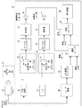
図1は、本発明によるビデオ波形モニタの例のハードウェア部分を中心とするブロック図である。図1に示すように、波形モニタ20は、カメラ12とつながって、入力信号を受ける。カメラ12は、被写体14に向けられている。カメラ12は、静止画又は動画を生成できる。カメラ12には、通常、絞り及び露出指数の調整機構があり、これらはカメラの操作者が制御しても良いし、カメラ12によって自動的に調整されるようにしても良い。カメラ12の出力信号は、波形モニタ20に入力される。カメラ12の出力信号のY’Cr’Cb又はR’G’B’コンポーネントは、ガンマ補正又はLog補正が行われていても良い。この補正は、カメラ12内で行われても良く、これによって、カメラの入射光から生じた信号を線形な関数から、非線形な伝達関数に変更し、出力信号が充分なダイナミック・レンジやビット・サイズを有するようにする。広く一般に使用されているガンマ伝達関数は、長年にわたりテレビジョン及びコンピュータ画像において使用されており、同時に、人間の視覚の非線形な明度関数を近似したものである。人間の視覚の明度関数は、立方根のべき乗関数(1/3の指数関数)で近似されることが多く、これら一般的なガンマ補正関数(sRGB、REC−601、REC709など)の多くは、1/2.2から1/2.6の範囲の指数関数によるべき乗に従ったものでもある。そこで、ガンマ補正を信号に適用した場合には、プライム表記法(「’」プライム(ダッシュとも呼ぶ)を付ける)が使用される(非特許文献2参照)。上述のように、この補正は、通常、カメラ12内で行われ、カメラの出力信号は、典型的には、R’、G’及びB’又はY’、Cb’及びCr’である。最近のカメラでは、ガンマ補正済み出力信号に加えて、新しい撮像素子のハイ・ダイナミック・レンジの光感度を更に圧縮するための録画用Log処理ハイ・ダイナミック・レンジ出力信号の両方を出力できるものもある。本発明の実施形態は、これら出力信号のどちらに対しても利用できる。
FIG. 1 is a block diagram centering on the hardware portion of an example of a video waveform monitor according to the present invention. As shown in FIG. 1, the
波形モニタ20では、カメラ12の出力信号が、入力プロセッサ30で最初に処理されて、画像中のデジタル・ルミナンス(輝度)信号Y’が取り出される。次に、デジタル・ルミナンス信号Y’は、精緻(fine)ミキサ40と、粗(coarse)ミキサ50とを通過し、続いて、第1ローパス・フィルタ60及び第2ローパス・フィルタ70をそれぞれ通過する。
In the
精緻ミキサ40には、例えば、周波数がFs/2の方形波入力信号によって制御されるマルチプレクサ42がある。なお、Fsは、デジタル・ルミナンス信号Y’のサンプル・レートである。粗ミキサ50には、例えば、周波数がFs/4の方形波入力信号によって制御されるマルチプレクサ52がある。精緻ミキサ40及びローパス・フィルタ60を通るパスは、精緻又はシャープ焦点パスである一方、ミキサ50及びローパス・フィルタ70を通るパスは、粗焦点又は被写界深度(DOF)のパスである。
The
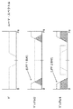
マルチプレクサ42及び52を駆動する信号は、好ましくは方形波信号であるので、混合(mixing)処理は、局部発振レート(つまり、焦点パスに応じてFs/2又はFs/4)でプラスのY’とマイナスのY’とを選択するデジタル・マルチプレクサとして実現できる。そこで、乗算器44及び54では、マイナス1が信号Y’に掛け算処理される。デジタル処理では、符号のない入力データに−1を掛け算する乗算器44及び54の機能は、符号のない入力データを単にマイナス符号にして表現したものにすぎず、これのため、処理を単純化できる。各ミキサの出力信号とローパス・フィルタの応答を重ねたものを図2に示す。図2が示すように、精緻ミキサ40は、数学的には、信号Y’×Fs/2の方形波入力信号の乗算処理を行うので、三角関数の積和公式に従って、両信号の周波数を加算した成分と、引き算した成分が現れ、これらはFs/2を中心とする鏡像関係となる。同様に、粗ミキサ50も、数学的には、信号Y’×Fs/4の方形波入力信号の乗算処理を行う。
Since the
精緻ミキサ40からのミキサ出力信号には、プラス又はマイナスの符号がついており、これは、ローパス・フィルタ60でフィルタ処理され、絶対値プロセッサ62により、このフィルタ処理出力信号の絶対値信号が得られる。同様に、粗ミキサ50からのミキサ出力信号には、プラス又はマイナスの符号がついており、これは、ローパス・フィルタ70でフィルタ処理され、絶対値プロセッサ72により、このフィルタ処理出力信号の絶対値信号が得られる。符号のない絶対値信号のそれぞれは、比較器64及び74で別々のしきい値とそれぞれ比較され、精緻焦点(フォーカス)の画像領域を示すための第1バイナリ(2値)ゲート信号を生成するのに加えて、粗焦点又はワイド焦点(被写界深度)の画像領域を示すための第2バイナリ・ゲート信号を生成する。
The mixer output signal from the
図1の例では、カメラ12からのオリジナル信号は、オプションで、ルーマ(Luma:輝度)変換部80でモノクローム(白黒)信号に変換され、続いて、遅延回路82で遅延されて、信号処理遅延のあるミキサとローパス・フィルタの2つのパスを通過する信号とタイミングが合致するようにする。このモノクローム信号は、スイッチ又はマルチプレクサ90及び96に印加され、これによって、それぞれ対応する比較器64又は74からのゲート出力信号によって、各ゲート信号に関して、着色に使用する異なる色が選択される。例えば、図1に示すように、精緻焦点を示すためには画像上で赤色が使用され、粗焦点を示すためには画像上で黄色が使用される。これに代えて、ゲート信号によって、他の色が選択されるようにしても良いし、クロスハッチや縞模様のような視覚的なパターンが選択されるようにしても良い。
In the example of FIG. 1, the original signal from the camera 12 is optionally converted into a monochrome (black and white) signal by a luma (Luma)
次に、黄色スイッチ90や赤色スイッチ96は、モノクローム画像のオリジナル部分に黄色又は赤色のどちらかを重ねて(オーバーレイ)挿入し、これによって、画像上で、焦点の深度(黄色)と、画像の最も空間周波数の高い領域(これは、画像の焦点が最も合っているカ所を示すので、赤色)を示す。残りの画素は、合焦レベルが所定の合焦しきい値から外れている画素であるから、表示装置98上で変更なしで表示するようにしても良い。もしルーマ変換部80を設けていて、これがアクティブな場合には、このオリジナル画像の非変更部分を白黒で示すようにする。別のやり方としては、オリジナル画像の非変更部分は、カメラ12から受けたものと同じままで表示する。合成された強調表示された画像は、次に、表示のために表示装置98へと送られる。実施形態によっては、表示装置98は、波形モニタ20から独立した外部モニタ又は外部表示装置としても良い。
Next, the
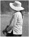
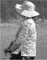
例えば、図4A及び4Bを参照すると、オリジナルの非変更モノクローム画像が図4Aに示されている。これは、図1のルーマ変換部80の出力信号から生成された画像である。図4Bを良く見てみると、モノクローム画像上に被写界深度を示す部分が黄色で重ねられて(オーバーレイ)強調表示される一方で、焦点の最も合った領域は、モノクローム画像上で赤色で示されている。なお、図4Bでは、図がカラーでないため、クロスハッチで黄色領域を示し、縦の縞模様で赤色領域を示している。赤色領域(最も合焦している領域)は、通常、黄色領域(大まかに合焦している領域、つまり、被写界深度の領域)に囲まれており、共通する縁がある。もちろん、被写界深度の領域や最も合焦した領域を示す色又はパターンは、ユーザが任意に選択可能である。再度、図1を参照すると、図4Bで黄色で示された領域は、黄色スイッチ90に入力される黄色の値に由来し、図4Bで赤色で示された領域は、赤色スイッチ96に入力される赤色の値に由来する。よって、所望の色又はパターンをスイッチ90及び96のカラー入力端子に供給すれば、異なる色又はパターンを実現することもできる。
For example, referring to FIGS. 4A and 4B, the original unmodified monochrome image is shown in FIG. 4A. This is an image generated from the output signal of the
指定した赤及び黄色の値を使用する場合、ゲート・スイッチ又はマルチプレクサ90及び96に入力される赤及び黄色マーカの色は、固定の彩度及び輝度のどちらでも良く、また、その代わりに、入力されたルミナンス信号に比例するようにしても良いし、これらの組み合わせでも良い。
When using the specified red and yellow values, the color of the red and yellow markers input to the gate switches or
別の実施形態では、波形モニタ20に強調表示される焦点領域が3つ以上あっても良い。例えば、波形モニタに図1で説明したような焦点パスを追加で設けても良く、ユーザが3つ、4つ又は任意の個数の別々の焦点領域を制御し、それぞれが個々のカラー・マーカ(ピクチャ・マーカ)を生成するようにしても良い。
In another embodiment, there may be more than two focal regions that are highlighted on the
動作においては、ユーザがユーザ・インタフェース(UI)22を用いて、波形モニタ20のいくつかのパラメータを制御する。例えば、ローパス・フィルタ60及び70のフィルタ・パラメータは、ユーザが選択できる。加えて、比較器64に入力される精緻合焦しきい値によって、ユーザは、どの画像領域を精緻焦点インジケータ(マーカ)で示すかを選択できる。実施形態によっては、ユーザが精緻合焦しきい値を非常に高く設定し、これによって、色でマーカを付けた画像上で被写界深度だけが示されるようにしても良い。また、ユーザは、ユーザ・インタフェース22を用いて、精緻及び粗マーカに関するカラー入力を選択する。上述のように、図1では、これらマーカを赤色(縦縞模様)及び黄色(クロスハッチ)として示すが、別の任意の色又はパターンを用いて、これら焦点領域を示すようにしても良い。
In operation, a user controls several parameters of the waveform monitor 20 using a user interface (UI) 22. For example, the filter parameters of the low pass filters 60 and 70 can be selected by the user. In addition, the fine focus threshold value input to the
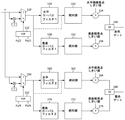
図3は、本発明の別の実施形態によるビデオ波形モニタの主要部分のブロック図である。図3では、特に図1と異なる部分を示している。詳しくは後述するが、大まかに言えば、図3の実施形態では、新たなフィルタのセットを精緻焦点パス及び粗焦点パスに追加し、水平及び垂直の両方向の焦点検出を可能にしている。図3の実施形態は、図1の残りの構成要素と共に動作するようにしても良い。例えば、図3のY’入力信号は、図1の入力プロセッサ30の出力信号としても良い。また、例えば、ORゲート140及び180のゲート出力信号は、図1の赤色スイッチ96及び黄色スイッチ90をそれぞれ制御するのにり利用されても良い。
FIG. 3 is a block diagram of the main parts of a video waveform monitor according to another embodiment of the present invention. FIG. 3 shows a different part from FIG. Although described in detail later, in the embodiment of FIG. 3, a new set of filters is added to the fine focus path and the coarse focus path to enable focus detection in both horizontal and vertical directions. The embodiment of FIG. 3 may operate with the remaining components of FIG. For example, the Y ′ input signal of FIG. 3 may be an output signal of the
図3の実施形態では、画像を水平及び垂直の両方向にスキャンするのに対し、図1の実施形態では、画像を水平方向にのみスキャンする。水平及び垂直の両方向にスキャンすることによって、焦点のマーキング処理の忠実性が向上する。 In the embodiment of FIG. 3, the image is scanned in both the horizontal and vertical directions, whereas in the embodiment of FIG. 1, the image is scanned only in the horizontal direction. Scanning in both the horizontal and vertical directions improves the fidelity of the focus marking process.
図1のように精緻焦点検出に関して1つのローパス・フィルタ60を設けるの代えて、図3の実施形態では、精緻垂直ローパス・フィルタ130に加えて、精緻水平ローパス・フィルタ120もある。精緻水平ローパス・フィルタ120は、水平方向に関してフィルタ処理を行い、精緻垂直ローパス・フィルタ130は、垂直方向に関してフィルタ処理を行う。水平及び垂直ローパス・フィルタ120及び130は、並列に結合しても良いし、別の選択肢としては、水平ローパス・フィルタ120の出力端子に垂直ローパス・フィルタ130を結合しても良く、これによって、システムは、垂直エッジではなく、水平エッジに対する感度が向上する。マルチプレクサ110は、XORゲート112の出力信号によって駆動される。XORゲート112は、好ましくは、Fs/2及びFh/2の周波数を有する方形波入力信号を受ける。上述のように、Fs/2は、Y’信号の周波数の2分の1の周波数である一方、Fh/2は、分析対象の特定のビデオ・フォーマットのライン・レートの2分の1である。XORゲート112をFs/2及びFh/2の2つの信号で駆動することで、2つ別々のマルチプレクサがあるのと同様な出力信号を生成できる。図示した実施形態では、ローパス・フィルタ120及び130のそれぞれを通過すると、上述と同様に動作する絶対値プロセッサ122及び132にそれぞれ供給される。
Instead of providing a single low-
2つのローパス・フィルタを有する精緻焦点パスに加えて、粗(coarse)焦点パスにも水平ローパス・フィルタ160及び垂直ローパス・フィルタ170があり、これらは絶対値プロセッサ162及び172にそれぞれ結合される。これら精緻焦点パスと粗焦点パスの違いとしては、XORゲート112及び152を駆動する信号と、比較器124、134、164及び174に設定されるしきい値がある。
In addition to the fine focus path having two low-pass filters, the coarse focus path also has a horizontal low-
ORゲート140は、赤色ゲート信号を生成する。赤色ゲート信号は、被分析対象の画像の水平エッジ又は垂直エッジのどちらかの周波数情報が精緻合焦しきい値の条件を満たす場合に、画像上に赤色を加えるための制御信号である。ORゲート180は、水平エッジ又は垂直エッジのどちらかが粗合焦しきい値を超える場合に黄色ゲート信号を生成する。いずれの場合でも、精緻及び粗焦点パスの両方についての垂直及び水平しきい値は、ユーザが、例えば、ユーザ・インタフェース22(図1参照)を用いることで設定可能である。
The OR
波形モニタ20やその任意の構成部分は、ASICのような特定用向けに設計された回路やFPGAにおいて、ファームウェアで実現しても良いし、又は、1つ以上のプロセッサ上で実行される1つ以上のソフトウェア・プロセスとして実現しても良い。別の実施形態では、波形モニタ20が、例えば、ファームウェア、ASIC、FPGA及びソフトウェア上で実行されるコンポーネント又は処理の組み合わせを含んでいても良い。
The waveform monitor 20 and its optional components may be implemented in firmware in a circuit or FPGA designed for a specific purpose, such as an ASIC, or may be executed on one or more processors. You may implement | achieve as the above software processes. In another embodiment, the
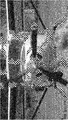
図5は、本発明の実施形態を用いて生成した表示例の別の例を示す。図5Aは、変更を加えていないオリジナルのモノクローム画像を示す。図5Bは、図5Aのオリジナルのモノクローム画像上に被写界深度を示す部分が黄色で重ねられて(オーバーレイ)強調表示される一方で、焦点の最も合った領域は、モノクローム画像上で赤色で示されている。なお、図4Bと同様に、図がカラーではないため、本願の図5Bでは、クロスハッチで黄色領域を示し、縦の縞模様で赤色領域を示している。 FIG. 5 shows another example of a display example generated using the embodiment of the present invention. FIG. 5A shows the original monochrome image without modification. FIG. 5B shows that the area of depth of field is highlighted in yellow (overlay) on the original monochrome image of FIG. 5A, while the most focused area is red on the monochrome image. It is shown. 4B, since the figure is not a color, in FIG. 5B of the present application, a yellow area is indicated by a cross hatch, and a red area is indicated by a vertical stripe pattern.
本発明の具体的な実施形態を図示すると共に説明してきたが、これは単に説明の都合によるものに過ぎず、本発明の精神と範囲から逸脱することなく、多様な変形が可能なことは明らかであろう。 While specific embodiments of the invention have been illustrated and described, it is to be understood that this is for illustrative purposes only and that various modifications can be made without departing from the spirit and scope of the invention. Will.
12 カメラ
14 被写体
20 波形モニタ
22 ユーザ・インタフェース
30 入力プロセッサ
40 精緻ミキサ
42 マルチプレクサ
44 乗算器
50 粗ミキサ
52 マルチプレクサ
54 乗算器
60 第1ローパス・フィルタ
62 第1絶対値プロセッサ
64 第1比較器
70 第2ローパス・フィルタ
72 第2絶対値プロセッサ
74 第2比較器
80 ルーマ変換部
82 遅延回路
90 黄色スイッチ
96 赤色スイッチ
110 マルチプレクサ
112 XORゲート
120 精緻水平ローパス・フィルタ
122 絶対値プロセッサ
124 比較器
130 精緻垂直ローパス・フィルタ
132 絶対値プロセッサ
134 比較器
140 ORゲート
150 マルチプレクサ
152 XORゲート
160 粗水平ローパス・フィルタ
164 比較器
170 粗垂直ローパス・フィルタ
174 比較器
180 ORゲート
12
Claims (2)
複数の画素から構成されるオリジナル画像を受ける処理と、
上記画素から周波数情報を抽出する処理と、
第1周波数しきい値を超える第1周波数範囲を選択する処理と
上記第1周波数しきい値と異なる第2周波数しきい値を超える第2周波数範囲を選択する処理と、
上記第1周波数範囲に該当するオリジナルの画素を選択的に変化させると共に上記第2周波数範囲に該当する上記オリジナルの画素を選択的に変化させることで上記オリジナル画像を変更し、変更画像を生成する処理と
を具える表示生成方法。 A method for generating an indication relating to an output signal of a measuring device, comprising:
Processing to receive an original image composed of a plurality of pixels;
A process of extracting frequency information from the pixels;
A process for selecting a first frequency range exceeding a first frequency threshold; a process for selecting a second frequency range exceeding a second frequency threshold different from the first frequency threshold;
The original image corresponding to the first frequency range is selectively changed and the original pixel corresponding to the second frequency range is selectively changed to change the original image and generate a changed image. A display generation method comprising processing and.
上記画像入力部で受けたオリジナル画像の画素に関する周波数情報を測定する測定システムと、
上記周波数情報から高周波数値を生成するよう構成された変換部と、
上記高周波数値の第1部分を第1制御情報として選択するよう構成された第1選択部と、
上記高周波数値の第2部分を第2制御情報として選択するよう構成された第2選択部と、
上記第1制御情報及び上記第2制御情報に基いて、上記オリジナル画像の選択された画素を変更する構成された変更部と
を具える波形モニタ。 A waveform monitor having an image input and coupled to a monitor for viewing a display of measured values,
A measurement system for measuring frequency information relating to pixels of the original image received by the image input unit;
A converter configured to generate a high-frequency numerical value from the frequency information;
A first selection unit configured to select the first part of the high frequency numerical value as first control information;
A second selection unit configured to select the second part of the high-frequency value as second control information;
A waveform monitor comprising: a changing unit configured to change a selected pixel of the original image based on the first control information and the second control information.
Applications Claiming Priority (4)
| Application Number | Priority Date | Filing Date | Title |
|---|---|---|---|
| US201461975624P | 2014-04-04 | 2014-04-04 | |
| US61/975624 | 2014-04-04 | ||
| US14/587,766 US10057566B2 (en) | 2014-04-04 | 2014-12-31 | Depth of field indication using focus-peaking picture markers |
| US14/587766 | 2014-12-31 |
Publications (1)
| Publication Number | Publication Date |
|---|---|
| JP2015201848A true JP2015201848A (en) | 2015-11-12 |
Family
ID=52824078
Family Applications (1)
| Application Number | Title | Priority Date | Filing Date |
|---|---|---|---|
| JP2015077591A Pending JP2015201848A (en) | 2014-04-04 | 2015-04-06 | display generation method and waveform monitor |
Country Status (4)
| Country | Link |
|---|---|
| US (1) | US10057566B2 (en) |
| EP (1) | EP2928179B1 (en) |
| JP (1) | JP2015201848A (en) |
| CN (1) | CN104980649B (en) |
Families Citing this family (3)
| Publication number | Priority date | Publication date | Assignee | Title |
|---|---|---|---|---|
| GB2575162A (en) * | 2018-05-08 | 2020-01-01 | Tektronix Inc | Image component delineation in a video test and measurement instrument |
| CN114584700B (en) * | 2020-11-30 | 2024-04-05 | 京东方科技集团股份有限公司 | Focusing marking method, marking device and electronic equipment |
| CN116074624B (en) * | 2022-07-22 | 2023-11-10 | 荣耀终端有限公司 | Focusing method and device |
Family Cites Families (10)
| Publication number | Priority date | Publication date | Assignee | Title |
|---|---|---|---|---|
| US6480300B1 (en) * | 1998-04-08 | 2002-11-12 | Fuji Photo Film Co., Ltd. | Image processing apparatus, image processing method and recording medium on which software for executing the image processing is recorded |
| JP2000147370A (en) * | 1998-11-18 | 2000-05-26 | Sony Corp | Imaging device |
| US7423781B2 (en) * | 2002-03-20 | 2008-09-09 | Ricoh Company, Ltd. | Image processor and image processing method for image enhancement using edge detection |
| GB2457867B (en) | 2007-10-08 | 2010-11-03 | Keymed | Electronic camera |
| JP5039570B2 (en) | 2008-01-09 | 2012-10-03 | キヤノン株式会社 | Display device, video display system, and display method |
| JP4453777B2 (en) * | 2008-07-15 | 2010-04-21 | 日本ビクター株式会社 | Image quality improving apparatus and method |
| WO2010073485A1 (en) * | 2008-12-22 | 2010-07-01 | 三菱電機株式会社 | Image processing apparatus and method, and image displaying apparatus |
| US8509482B2 (en) * | 2009-12-21 | 2013-08-13 | Canon Kabushiki Kaisha | Subject tracking apparatus, subject region extraction apparatus, and control methods therefor |
| JP2012247897A (en) * | 2011-05-26 | 2012-12-13 | Sony Corp | Image processing apparatus and method of processing image |
| CN103988489B (en) * | 2011-09-30 | 2017-12-01 | 富士胶片株式会社 | Imaging device and imaging method |
-
2014
- 2014-12-31 US US14/587,766 patent/US10057566B2/en active Active
-
2015
- 2015-04-02 EP EP15162449.1A patent/EP2928179B1/en active Active
- 2015-04-02 CN CN201510153581.7A patent/CN104980649B/en active Active
- 2015-04-06 JP JP2015077591A patent/JP2015201848A/en active Pending
Also Published As
| Publication number | Publication date |
|---|---|
| US10057566B2 (en) | 2018-08-21 |
| US20150288957A1 (en) | 2015-10-08 |
| EP2928179A1 (en) | 2015-10-07 |
| CN104980649B (en) | 2019-12-17 |
| CN104980649A (en) | 2015-10-14 |
| EP2928179B1 (en) | 2019-06-12 |
Similar Documents
| Publication | Publication Date | Title |
|---|---|---|
| WO2012132241A1 (en) | Image processing apparatus, imaging system, and image processing system | |
| US20150153559A1 (en) | Image processing apparatus, imaging system, and image processing system | |
| US20070242141A1 (en) | Adjustable neutral density filter system for dynamic range compression from scene to imaging sensor | |
| WO2019031086A1 (en) | Image processing system, server device, image processing method, and image processing program | |
| EP2928177B1 (en) | F-stop weighted waveform with picture monitor markers | |
| EP3576402A1 (en) | Image processing apparatus, image processing method, and storage medium | |
| CN109891869B (en) | Video signal processing apparatus, video signal processing method, and video signal processing system | |
| JP6229625B2 (en) | Color gamut conversion apparatus, color gamut conversion method, and color gamut conversion program | |
| JP2015201848A (en) | display generation method and waveform monitor | |
| JP2017201249A (en) | Change degree deriving device, change degree deriving system, change degree deriving method, color known body and program used therefor | |
| WO2019160041A1 (en) | Image processing device, microscope system, image processing method and image processing program | |
| JP5034927B2 (en) | Information acquisition apparatus, information acquisition method, and information acquisition program | |
| US8363151B2 (en) | Focus-adjustment signal generating apparatus and method, and imaging apparatus and method, with manual focus adjustments | |
| JP2015035782A (en) | Image processing device, imaging device, microscope system, image processing method, and image processing program | |
| WO2019181560A1 (en) | Image processing device, image pickup device, image processing method, and program | |
| US8508613B2 (en) | Image capturing apparatus | |
| JP2017143504A5 (en) | ||
| JP5673186B2 (en) | Imaging apparatus and interpolation processing method of imaging apparatus | |
| JP2010041507A (en) | View finder display circuit | |
| JP2021068925A (en) | Image processing apparatus and image processing method, imaging apparatus, and program | |
| US20250350816A1 (en) | Imaging device, imaging method, and imaging system | |
| Bajić et al. | Implementation of the optical beam profiler system using LabVIEW software package and low-cost web camera | |
| Farsani et al. | Robust and efficient modulation transfer function measurement with CMOS color sensors | |
| JP2011055280A (en) | Image processing apparatus, image processing method and electronic camera | |
| JP2015111775A (en) | Imaging apparatus, control method thereof, and program |
Legal Events
| Date | Code | Title | Description |
|---|---|---|---|
| A625 | Written request for application examination (by other person) |
Free format text: JAPANESE INTERMEDIATE CODE: A625 Effective date: 20180323 |
|
| A977 | Report on retrieval |
Free format text: JAPANESE INTERMEDIATE CODE: A971007 Effective date: 20190408 |
|
| A131 | Notification of reasons for refusal |
Free format text: JAPANESE INTERMEDIATE CODE: A131 Effective date: 20190416 |
|
| A601 | Written request for extension of time |
Free format text: JAPANESE INTERMEDIATE CODE: A601 Effective date: 20190716 |
|
| A601 | Written request for extension of time |
Free format text: JAPANESE INTERMEDIATE CODE: A601 Effective date: 20190913 |
|
| A711 | Notification of change in applicant |
Free format text: JAPANESE INTERMEDIATE CODE: A711 Effective date: 20191024 |
|
| A521 | Request for written amendment filed |
Free format text: JAPANESE INTERMEDIATE CODE: A821 Effective date: 20191024 |
|
| A02 | Decision of refusal |
Free format text: JAPANESE INTERMEDIATE CODE: A02 Effective date: 20191217 |