JP2015200405A - Lid body of cleaning hole joint, and cleaning hole joint - Google Patents
Lid body of cleaning hole joint, and cleaning hole joint Download PDFInfo
- Publication number
- JP2015200405A JP2015200405A JP2015017841A JP2015017841A JP2015200405A JP 2015200405 A JP2015200405 A JP 2015200405A JP 2015017841 A JP2015017841 A JP 2015017841A JP 2015017841 A JP2015017841 A JP 2015017841A JP 2015200405 A JP2015200405 A JP 2015200405A
- Authority
- JP
- Japan
- Prior art keywords
- lid
- joint
- cleaning
- tool
- cleaning port
- Prior art date
- Legal status (The legal status is an assumption and is not a legal conclusion. Google has not performed a legal analysis and makes no representation as to the accuracy of the status listed.)
- Granted
Links
Images


Abstract
Description
本発明は、掃除口継手の蓋体及び掃除口継手に関する。 The present invention relates to a lid for a cleaning port joint and a cleaning port joint.
配管内部の点検や掃除を行うため、蓋体によって開閉可能とされた掃除口を備えた掃除口継手が用いられている。このような掃除口継手の蓋体には、開閉を行うための突起等が設けられている。蓋体が堅く締まっていて手で開けられない場合等には、工具を用いて蓋体を開くことも行われている。 In order to inspect and clean the inside of the piping, a cleaning port joint having a cleaning port that can be opened and closed by a lid is used. The lid of such a cleaning port joint is provided with a protrusion or the like for opening and closing. When the lid is tight and cannot be opened by hand, the lid is also opened using a tool.
特許文献1には、蓋体に凸状部を設け、この凸状部にドライバーやモンキーレンチ等の汎用工具を掛けて蓋体を開閉できるようにした構成が開示されている。 Patent Document 1 discloses a configuration in which a convex portion is provided on the lid, and the lid can be opened and closed by applying a general-purpose tool such as a screwdriver or a monkey wrench to the convex portion.
また、特許文献2には、有底円筒状の封止部を有した蓋体が開示されている。この蓋体は、封止部の内部に、その底面から突起する把持部が形成され、この把持部に工具などを係合させる治具孔が形成されている。 Further, Patent Document 2 discloses a lid having a bottomed cylindrical sealing portion. The lid is formed with a grip portion protruding from the bottom surface inside the sealing portion, and a jig hole for engaging a tool or the like with the grip portion.
しかしながら、特許文献1に開示された構成においては、凸状部が蓋体から突出している。このため、掃除口継手の周辺に、凸状部が回転可能で、凸状部に工具を掛けることのできるスペースを確保する必要があるが、近年、建物の共用部や専有部のスペースを広くするために配管を納めるパイプスペースは縮小傾向にあり、掃除口継手のためのスペースを設けることが困難になっている。 However, in the configuration disclosed in Patent Document 1, the convex portion protrudes from the lid. For this reason, it is necessary to secure a space around the cleaning port joint where the convex portion can rotate and a tool can be hung on the convex portion. Therefore, the pipe space for storing the piping tends to be reduced, and it is difficult to provide a space for the cleaning joint.
特許文献2に開示された構成においては、把持部が有底円筒状の封止部内に形成されているため、省スペース化を図ることができる。
しかし、この蓋体を工具で開閉させるには、把持部の先端部に形成された治具孔に挿入可能な専用の棒状治具を用いる必要がある。この場合、専用の治具を用意しなければならないのはコストもかかり不便である。
そこで、本発明は、省スペース化を図りつつ、汎用工具を用いて容易に開閉操作を行うことのできる掃除口継手の蓋体及びそれを用いた掃除口継手を提供する。
In the configuration disclosed in Patent Literature 2, since the gripping portion is formed in the bottomed cylindrical sealing portion, space saving can be achieved.
However, in order to open and close the lid with a tool, it is necessary to use a dedicated bar-shaped jig that can be inserted into a jig hole formed at the tip of the gripping part. In this case, it is expensive and inconvenient to prepare a dedicated jig.
Therefore, the present invention provides a cover for a cleaning port joint that can be easily opened and closed using a general-purpose tool while saving space, and a cleaning port joint using the same.
本発明は、上記課題を解決するため、以下の手段を採用する。
この発明に係る掃除口継手の蓋体は、前記掃除口部に挿入される挿入部と、前記挿入部の一端から径方向外方に延びるよう形成された環状のフランジ部と、前記挿入部の中心軸周りに回転させることによって前記掃除口部に形成された複数の係合溝に係合される複数の係合突起と、前記フランジ部において、前記フランジ部の中心を挟んだ両側に形成された一対の工具係合溝と、を備えることを特徴とする。
このような構成によれば、工具係合溝は、フランジ部の中心を挟んだ両側に形成されているため、例えばドライバーの軸部等、棒状の工具を工具係合溝に係合させることで、蓋体を回転させることができる。また、工具を回すことによる力は、蓋体の最外周部であるフランジ部に伝達されるので、軽い力で蓋体を回転させることが可能となる。
そして、蓋体には、ドライバーの軸部等の棒状の工具を係合できる程度の深さを有した工具係合溝を形成すれば良いので、フランジ部からの突出寸法を最小限に抑えることができる。
The present invention employs the following means in order to solve the above problems.
The lid of the cleaning port joint according to the present invention includes an insertion portion to be inserted into the cleaning port portion, an annular flange portion formed to extend radially outward from one end of the insertion portion, and the insertion portion. A plurality of engagement protrusions engaged with a plurality of engagement grooves formed in the cleaning port portion by rotating around a central axis, and the flange portion are formed on both sides sandwiching the center of the flange portion. And a pair of tool engaging grooves.
According to such a configuration, since the tool engaging groove is formed on both sides of the center of the flange portion, for example, by engaging a rod-shaped tool such as a shaft portion of a driver with the tool engaging groove. The lid can be rotated. Moreover, since the force by turning a tool is transmitted to the flange part which is the outermost peripheral part of a cover body, it becomes possible to rotate a cover body by light force.
And, it is only necessary to form a tool engagement groove with a depth that can engage a rod-shaped tool such as a driver's shaft in the lid, so that the projecting dimension from the flange is minimized. Can do.
また、この発明に係る掃除口継手の蓋体において、前記工具係合溝は、前記フランジ部の中心を挟んだ両側において、それぞれ前記フランジ部の周方向の一部に形成された切欠き部または凹部によって形成されていてもよい。
このように構成することで、蓋体のフランジ部からの突出寸法を最小限に抑えることができる。
Further, in the lid of the cleaning port joint according to the present invention, the tool engaging groove is a notch portion formed on a part of the flange portion in the circumferential direction on both sides sandwiching the center of the flange portion. It may be formed by a recess.
By comprising in this way, the protrusion dimension from the flange part of a cover body can be suppressed to the minimum.
また、この発明に係る掃除口継手の蓋体において、前記工具係合溝は、前記フランジ部の中心を挟んだ両側のそれぞれにおいて、前記フランジ部の周方向に間隔を空けて前記フランジ部から立ち上がる一対の立ち上がり壁を備えていてもよい。
このような構成では、一対の立ち上がり壁の間に工具を係合させて蓋体を回転させることができる。この立ち上がり壁は、棒状の工具を係合させるだけの高さを有していれば良く、蓋体のフランジ部からの突出寸法を最小限に抑えることができる。
In the lid of the cleaning port joint according to the present invention, the tool engaging groove rises from the flange portion at intervals in the circumferential direction of the flange portion on each of both sides sandwiching the center of the flange portion. A pair of rising walls may be provided.
In such a configuration, the lid can be rotated by engaging a tool between the pair of rising walls. The rising wall only needs to have a height sufficient to engage with a rod-shaped tool, and the protruding dimension from the flange portion of the lid can be minimized.
また、前記フランジ部の内側には、偏平な筒状に形成された摘まみ部が形成され、前記摘まみ部の内空が工具挿入部であってもよい。
このような構成では、摘まみ部を把持して蓋体を回転させることが可能となる。また、工具挿入部に工具を挿入して工具を回転させることにより蓋体を回転させることも可能となる。
Further, a knob part formed in a flat cylindrical shape may be formed inside the flange part, and an inner space of the knob part may be a tool insertion part.
In such a configuration, it is possible to grip the knob and rotate the lid. It is also possible to rotate the lid by inserting the tool into the tool insertion portion and rotating the tool.
この発明に係る掃除口継手は、両端部にパイプが接続されるパイプ接続部を有するとともに、前記パイプ接続部どうしの間に形成された掃除口部を備えた継手本体と、前記継手本体の前記掃除口部に装着可能な上記したような蓋体と、を備えることを特徴とする。
このような掃除口継手によれば、棒状の工具を工具係合溝に係合させることで、蓋体を回転させることができる。また、軽い力で蓋体を回転させることが可能となる。しかも、蓋体は、フランジ部からの突出寸法を最小限に抑えることができるので、掃除口継手の小型化を図ることができる。
The cleaning port joint according to the present invention has a pipe connection part to which pipes are connected to both ends, a joint body provided with a cleaning port part formed between the pipe connection parts, and the joint body And a lid as described above that can be attached to the cleaning port.
According to such a cleaning port joint, the lid can be rotated by engaging the rod-shaped tool with the tool engaging groove. Further, the lid can be rotated with a light force. Moreover, since the lid can minimize the projecting dimension from the flange portion, the size of the cleaning joint can be reduced.
この発明に係る掃除口継手の前記継手本体及び前記蓋体には、それぞれ紐状部材を挿通可能な通し孔が形成されていてもよい。
このような掃除口継手によれば、通し孔に紐状部材を挿通させて蓋体と継手本体とを連結させることができる。
A through hole through which a string-like member can be inserted may be formed in the joint main body and the lid body of the cleaning joint according to the present invention.
According to such a cleaning port joint, the lid member and the joint body can be connected by inserting the string-like member through the through hole.
この発明に係る掃除口継手の蓋体及びそれを用いた掃除口継手によれば、蓋体のフランジ部からの突出寸法を最小限に抑えることによって省スペース化を図ることができる。また、フランジ部に形成した工具係合溝に、ドライバーの軸部等、棒状の工具、すなわち汎用工具を係合させることによって、蓋体を容易に開閉操作することが可能となる。 According to the lid of the cleaning joint and the cleaning joint using the same according to the present invention, it is possible to save space by minimizing the projecting dimension from the flange portion of the lid. Further, the lid can be easily opened and closed by engaging a rod-shaped tool such as a driver shaft portion, that is, a general-purpose tool, with the tool engaging groove formed in the flange portion.
以下、添付図面を参照して、本発明による掃除口継手の蓋体及びそれを用いた掃除口継手を実施するための形態を説明する。しかし、本発明はこの実施形態のみに限定されるものではない。 Hereinafter, with reference to an accompanying drawing, a form for carrying out a cover of a cleaning mouth joint by the present invention and a cleaning mouth joint using the same is explained. However, the present invention is not limited only to this embodiment.
図1は、本実施形態に係る掃除口継手の部品構成を示す断面図である。図2は、掃除口継手の継手本体を示す斜視図である。図3は、掃除口継手を掃除口部側から視た図である。図4は、蓋体を継手本体の掃除口部に対向させた状態を示す断面図である。図5は、掃除口継手を構成する蓋体を示す図であり、(a)は蓋体を掃除口継手に装着した状態で外側を向く側から見た斜視図、(b)は蓋体を掃除口継手に装着した状態で配管内側となる側から見た斜視図である。図6は、蓋体を掃除口継手に装着した状態で配管内側となる側から見た図である。
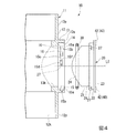
図1に示すように、掃除口継手10は、排水管の一部に組み込まれるもので、継手本体11と、蓋体20と、環状のパッキン30と、を備えている。
FIG. 1 is a cross-sectional view showing a component configuration of a cleaning joint according to the present embodiment. FIG. 2 is a perspective view showing a joint body of the cleaning joint. FIG. 3 is a view of the cleaning port joint as viewed from the cleaning port side. FIG. 4 is a cross-sectional view showing a state in which the lid is opposed to the cleaning port of the joint body. FIG. 5 is a view showing a lid constituting the cleaning joint, wherein (a) is a perspective view seen from the side facing the outside in a state where the lid is attached to the cleaning joint, and (b) is a perspective view of the lid. It is the perspective view seen from the side which becomes piping inner side in the state with which the cleaning mouth joint was mounted | worn. FIG. 6 is a view as seen from the inner side of the pipe with the lid attached to the cleaning joint.
As shown in FIG. 1, the cleaning joint 10 is incorporated into a part of the drain pipe, and includes a
図1〜図4に示すように、継手本体11は、主管部材12と、掃除口部13と、を一体に備えている。
主管部材12は、管状をなし、排水管を構成するパイプ(図示無し)が接続させるパイプ接続部12p,12pを両端部に備えている。この実施形態では、主管部材12は、一方のパイプ接続部12pと他方のパイプ接続部12pとが直線的に配置されたストレート形状をなしているが、主管部材12は湾曲または屈曲していてもよい。
As shown in FIGS. 1 to 4, the
The
掃除口部13は、円筒状で、パイプ接続部12p,12p間において、主管部材12に接続されている。掃除口部13は、主管部材12の軸線L1方向に対して直交する側方に向けて延びるよう形成されている。掃除口部13の内側に形成された管路13kは、主管部材12内のメイン管路12kに連通している。
The cleaning
掃除口部13において、主管部材12から離間した側の先端部13sの内周面には、管路13kよりも内径が拡大された被係合部14が形成されている。被係合部14には、掃除口部13の周方向に間隔を空けて複数の係合溝15が形成されている。
また、掃除口部13の管路13kと被係合部14との間には、管路13kの軸線方向に直交する受け面16が形成されている。
In the cleaning
Further, a receiving
図4に示すように、各係合溝15は、掃除口部13の先端部13sに開口した開口部15aと、開口部15aから掃除口部13の軸線L2方向に平行に主管部材12側に向かって延びる導入溝15bと、導入溝15bの主管部材12側の端部から主管部材12の周方向に沿って延びる摺動溝15cと、摺動溝15cの終端に形成された終端定着部15dと、を備えている。
As shown in FIG. 4, each
摺動溝15cは、導入溝15b側から終端定着部15dに向かうに従って、主管部材12に漸次近づくよう傾斜して形成されている。
終端定着部15dは、掃除口部13の先端部13s側の溝内周面15fが掃除口部13の軸線方向に直交するよう形成されている。
The sliding
The
本実施形態において、上記の係合溝15は、掃除口部13の周方向に3組設けられている。
ここで、図3に示すように、3組の係合溝15のうちの一つは、掃除口部13の周方向に沿った方向の開口部15aおよび導入溝15bの幅W1が、他の二つの係合溝15の開口部15aおよび導入溝15bの幅W2よりも大きくなるよう設定されている。
In the present embodiment, three sets of the
Here, as shown in FIG. 3, one of the three sets of
図4、図5、図6に示すように、蓋体20は、挿入筒部21と、係合部22と、フランジ部23と、閉塞板24と、を一体に備えている。
As shown in FIGS. 4, 5, and 6, the
挿入筒部21は、円筒状をなし、掃除口部13の管路13kの内径よりもわずかに小さい外径を有して、掃除口部13内に挿入可能とされている。
The
係合部22は、挿入筒部21の一端側において、挿入筒部21よりも外周側に拡径した円筒状をなしている。係合部22は、その外径が、掃除口部13の管路13kの内径よりも大きく、かつ被係合部14の内径よりも小さく設定されている。この係合部22と挿入筒部21との間には、挿入筒部21の軸線に直交する面内に位置する段部25が形成されている。
The
図6に示すように、係合部22の外周面には、周方向に間隔を空けて、係合溝15と同数の係合突起27が形成されている。この実施形態では、係合突起27は3個設けられている。そして、係合突起27は、係合部22の周方向に沿った幅が、係合溝15に挿入可能な寸法で形成されている。3個の係合突起27のうちの一つの係合突起27の幅W3は、他の二つの係合突起27の幅W4よりも大きく設定されている。
As shown in FIG. 6, the same number of engaging
図4、図5に示すように、フランジ部23は、係合部22において挿入筒部21側とは反対側の端部に、係合部22から外周側に延びて形成されている。このフランジ部23は、外径が被係合部14の内径よりも大きくなるよう設定されている。
As shown in FIGS. 4 and 5, the
閉塞板24は、挿入筒部21の他端側の開口を閉塞するよう設けられている。閉塞板24は、後述するようにして蓋体20を掃除口部13に装着して閉状態としたときに、主管部材12のメイン管路12kの内周面に連続するよう湾曲して形成されている。また、挿入筒部21の他端側の端部は、この閉塞板24の外周部に沿うような形状に形成されている。
The closing
図5(a)に示すように、蓋体20において、挿入筒部21の内側には、蓋体20を開閉する際に作業者が掴むための摘まみ部26が設けられている。摘まみ部26は、挿入筒部21の内側において、閉塞板24から挿入筒部21の軸線方向に沿って突出している。
摘まみ部26は、その先端部26sが、フランジ部23よりも閉塞板24側に位置するよう形成されている。これにより、後述する工具係合溝40に係合させる工具が摘み部26に干渉しないようになっている。また、摘まみ部26は蓋体20の挿入筒部21内に収まり、挿入筒部21は掃除口継手10の掃除口部13内部に収まるため、掃除口継手10全体として省スペース化できる。
この実施形態において、摘まみ部26は、二個一対で、挿入筒部21の中心を挟んでその両側に、挿入筒部21の直径方向に沿って配置されている。
As shown in FIG. 5A, in the
The
In this embodiment, the
この蓋体20は、工具係合溝40を備えている。
工具係合溝40は、フランジ部23において、挿入筒部21の中心軸を挟んで対向する位置にそれぞれ形成された、切欠き41および立ち上がり壁42と、から形成されている。
The
The
切欠き41は、フランジ部23の周方向の一部を切欠くことによって形成され、フランジ部23の直径方向に連続し、ドライバーの軸部等、汎用工具を挿入できる幅で形成されている。この切欠き41を形成することによって、切欠き41の内側には、挿入筒部21の先端面21sが露出している。
The
立ち上がり壁42は、フランジ部23の周方向に沿って間隔を空けて二個一対で設けられている。立ち上がり壁42は、切欠き41の両側に沿って、それぞれフランジ部23から立ち上がるよう形成されている。
ここで、立ち上がり壁42のフランジ部23からの立ち上がり寸法は、フランジ部23の厚さと立ち上がり壁42の立ち上がり寸法の合計が、使用が想定されるドライバーの軸部の径寸法の1/2程度となるように設定するのが好ましい。
Two rising
Here, the rising dimension of the rising
図4に示すように、このような蓋体20を掃除口部13に装着するには、蓋体20と掃除口部13との間にパッキン30を介在させた状態で、挿入筒部21を継手本体11の管路13k内に挿入し、係合部22を掃除口部13の被係合部14に係合させる。係合部22を被係合部14に係合させるには、各係合突起27を、係合溝15に挿入する。このとき、係合突起27および係合溝15の開口部15aは、一つが他の二つよりも幅が広く形成されているので、掃除口部13に対し、蓋体20は、予め決められた向きで挿入される。これにより、後述するように蓋体20を閉状態としたとき、蓋体20の閉塞板24が主管部材12のメイン管路12kの内周面に連続し、メイン管路12k内に突出しないように蓋体20を挿入させることができる。
As shown in FIG. 4, in order to attach such a
図7は、蓋体を継手本体11の掃除口部13に挿入した状態を示す断面図である。図8は、蓋体20を継手本体11の掃除口部13に挿入した状態を、継手本体11の内側から見た斜視図である。
図7、図8に示すように、蓋体20をそのまま掃除口部13に押し込むと、係合突起27が係合溝15の導入溝15bに沿って移動し、導入溝15bの終端に突き当たることによって、蓋体20の移動が規制される。
蓋体20を挿入口部13内に押し込んで挿入した状態では、蓋体20の挿入筒部21の先端部21tおよび閉塞板24が、メイン管路12k内に突出する。
FIG. 7 is a cross-sectional view showing a state in which the lid is inserted into the cleaning
As shown in FIGS. 7 and 8, when the
In a state where the
次いで、蓋体20を、掃除口部13の中心軸線L2回りに回転させる。そうすると、図4に示す係合突起27が同図に示す係合溝15の摺動溝15cに沿って終端定着部15d側にスライドする。摺動溝15cは、図4に示すように導入溝15b側から終端定着部15dに向かうに従って、主管部材12に漸次近づくよう傾斜しているので、係合突起27がスライドして終端定着部15dに向かうに従って、蓋体20は主管部材12側に変位する。
このとき、図7に示すように、パッキン30は、蓋体20の段部25と、掃除口部13の受け面16との間に挟み込まれており、蓋体20が主管部材12側に変位するにしたがって徐々に押しつぶされる。
Next, the
At this time, as shown in FIG. 7, the packing 30 is sandwiched between the
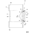
図9は、蓋体20を継手本体11の掃除口部13に装着した閉状態を示す断面図である。図10は、蓋体20を継手本体11の掃除口部13に装着した閉状態を、継手本体11の内側から見た斜視図である。図11は、蓋体20を継手本体11の掃除口部13に装着した閉状態を、掃除口部13側から見た図である。
蓋体20をさらに回転させ、図1に示す係合突起27が係合溝15の終端定着部15dに到達すると、蓋体20のそれ以上の回転が規制される。これにより、蓋体20は閉状態となる。
FIG. 9 is a cross-sectional view showing a closed state in which the
When the
図9に示すように、この閉状態で、パッキン30は、蓋体20の段部25と掃除口部13の受け面16との間で、確実な止水性を発揮できる所定の圧縮率で、掃除口部13の軸方向に圧縮されるようになっている。
また、この閉状態において、係合突起27は、圧縮されたパッキン30の反力により、係合溝15の終端定着部15dにおいて、掃除口部13の先端部13s側の溝内周面15f側に押圧されている。この溝内周面15fは、摺動溝15cのように傾斜しておらず、掃除口部13の軸線L2方向に直交するよう形成されているので、パッキン30の反力によって係合突起27が摺動溝15c側に変位して蓋体20が緩むのを防止できるようになっている。
As shown in FIG. 9, in this closed state, the packing 30 has a predetermined compression rate that can exhibit a reliable water stop between the
Further, in this closed state, the
図9、図10に示すように蓋体20を閉状態とすると、蓋体20の閉塞板24が、主管部材12のメイン管路12kの内周面に連続し、メイン管路12k内に突出しないようになっている。これにより、掃除口継手10の蓋体20の部分で、汚水が溜まったり、メイン管路12k内の排水の流れに損失を与えるのを抑えることができる。
When the
蓋体20を掃除口部13から取り外すには、蓋体20を上記とは反対方向に回転させる。蓋体20を反対方向に回転させると、図4に示す蓋体20の各係合突起27が係合溝15の終端定着部15dから摺動溝15cに沿ってスライドする。
図4に示す係合突起27が係合溝15の導入溝15bに到達すると、蓋体20のそれ以上の回転が規制される。そこで、蓋体20を掃除口部13から引き抜くと、係合突起27が係合溝15の導入溝15bに沿ってスライドする。そして、係合突起27が、開口部15aから離脱することにより、蓋体20が掃除口部13から取り外される。
In order to remove the
When the
上記したように蓋体20を開閉するとき、作業者は、挿入筒部21の内側に設けられた摘まみ部26を把持して蓋体20を回転させることができる。
また、蓋体20を閉状態から開くときには、長期間閉状態を継続したために蓋体20が掃除口部13に固着している場合や、パッキン30の反力によって係合突起27が係合溝15の溝内周面15fに押圧されることで生じる摩擦力が大きい場合、摘み部26を掴んだのでは蓋体20を回転させるのが困難なことがある。そのような場合には、図11に示すように、ドライバーの軸部等の棒状の工具Tを、フランジ部23の径方向両側にそれぞれ形成された立ち上がり壁42,42の間から切欠き41に挿入する。そして、ドライバーの軸部等を、挿入筒部21の中心軸周りに旋回させる。すると、工具Tから、フランジ部23の径方向両側の立ち上がり壁42および切欠き41に力が伝達され、蓋体20を回転させることができる。
When opening and closing the
Further, when the
上述した蓋体20及びそれを用いた掃除口継手10によれば、フランジ部23において、フランジ部23の中心を挟んだ両側に形成された一対の工具係合溝40を備えている。
工具係合溝40は、フランジ部23の中心を挟んだ両側に形成されているため、例えばドライバーの軸部等、棒状の工具Tを工具係合溝40に係合させることで、蓋体20を回転させることができる。また、力点となる工具Tの持ち手は蓋体20の最外周部であるフランジ部23よりも外側になり、蓋体20の中心軸からもっとも離れた位置にあるので、てこの原理によって軽い力で蓋体20を回転させることが可能となる。このようにして、ドライバーの軸部等、棒状の工具、すなわち汎用工具を係合させることによって、蓋体20を容易に開閉操作することが可能となる。
According to the
Since the
そして、蓋体20には、工具係合溝40として切欠き部41および立ち上がり壁42を形成すれば良いので、フランジ部23からの突出寸法を最小限に抑えることができる。
このようにして、蓋体20のフランジ部23からの突出寸法を最小限に抑えて小型化を図ることによって、掃除口継手10の小型化および省スペース化を図ることができる。
And since the
In this way, by minimizing the projection size of the
(その他の実施形態)
なお、本発明の掃除口継手の蓋体、及びそれを用いた掃除口継手は、図面を参照して説明した上述の各実施形態に限定されるものではなく、その技術的範囲において様々な変形例が考えられる。
(Other embodiments)
The lid of the cleaning port joint of the present invention and the cleaning port joint using the same are not limited to the above-described embodiments described with reference to the drawings, and various modifications are possible within the technical scope thereof. Examples are possible.
例えば、上記実施形態で示したような、一対の切欠き部41および立ち上がり壁42からなる工具係合溝40は、フランジ部23の周方向に異なる角度で複数組設けるようにしても良い。工具係合溝40をフランジ部23の周方向に異なる角度で設けることにより、持ち手が大きい工具Tを用いても、パイプ接続部12pの外周と工具Tの持ち手が干渉して工具Tを工具係合溝40に係合できないのを回避できる。また、工具係合溝40を複数組設けることにより、パイプスペースの形状に応じて回転しやすい角度で工具Tを係合させることができる。
For example, a plurality of sets of
また、工具係合溝40は、一対の切欠き部41および立ち上がり壁42からなるようにしたが、切欠き部41または立ち上がり壁42の一方のみで工具係合溝40を構成してもよい。
In addition, the
さらに、工具係合溝40は、フランジ部23の周方向の一部を切欠くことによって、フランジ部23の厚さ分の深さを有しているが、これに限らず、フランジ部23の周方向の一部に凹部を形成することによって工具係合溝40を形成してもよい。
Furthermore, the
さらに、工具係合溝40は、蓋体20を回転させるときに、工具が不用意に抜けず、確実に係合できるように、工具Tが当たる溝側面を、フランジ部23の先端面側に行くにしたがって工具係合溝40の内側に突出するよう傾斜させてもよい。
Further, the
さらに、上記実施形態では、工具係合溝40がフランジ部23の中心を挟んだ両側に形成されているとしたが、フランジ部23の中心から少し離れた点を挟んだ両側に形成されていてもよい。こうすることで、パイプ接続部12pの外周と工具Tの持ち手が干渉しにくくなる。
Furthermore, in the said embodiment, although the
さらに、フランジ部23は、係合部22において挿入筒部21側とは反対側の端部に、係合部22から外周側に延びて形成されているとしたが、係合部22から外周側に延びておらず、係合部22が掃除口部13の先端部13sよりも掃除口部13の開口部側に突出し、係合部22が突出した部分に工具係合溝40を形成してもよい。
Further, the
また、上記実施形態では、摘まみ部26は、その先端部26sが、工具係合溝40に係合させる工具Tが干渉しないようフランジ部23よりも閉塞板24側に位置するよう形成したが、これに限るものではなく、蓋体20を掃除口側から見たときに摘まみ部26の先端部26sと工具Tとが重ならない様に摘まみ部26を設ければよい。例えば、フランジ部23の径方向両側に設けた工具係合溝40に対し、摘み部26を蓋体20の中心軸回りに回転させた方向にオフセットさせて設けてもよい。
Moreover, in the said embodiment, although the knob | pick
また、挿入された工具Tを挟むように工具係合溝40よりも広い幅で平行に設けた二個一対の板状としてもよい。これにより、一対の摘み部26、26の間に、工具係合溝40に係合させる工具Tが収まるようにすれば、工具Tと摘み部26との干渉を回避できる。
このように工具Tと摘み部26との干渉を回避できる場合には、摘まみ部26の先端部26sがフランジ部23以上に突出していてもよいし、摘まみ部26は二個一対でなく閉塞板24側で連通して一個の摘まみ部となっていてもよい。
Moreover, it is good also as a pair of 2 plate shape provided in parallel with the width | variety wider than the tool engagement groove |
When the interference between the tool T and the
さらに、摘まみ部26の先端部26sと工具係合溝40に係合された工具との間に作業者の手が入る隙間ができる程度に摘まみ部26を閉塞板24から低く突出していてもよい。
こうすることで、パイプスペースの開口部やパイプスペース自体が狭いためにフランジ部23の外側となる工具Tの持ち手を持って回転することができない場合や、さらなる省スペース化のため蓋体20の突出寸法を縮小し力を入れて回すのに困難なほど摘まみ部26を小さくした場合でも、工具係合溝40の間の工具Tを把持して蓋体20を回転させることができる。
Furthermore, the
By doing so, when the opening of the pipe space and the pipe space itself are narrow, it is not possible to rotate with the handle of the tool T outside the
さらに、例えば、係合突起27および係合溝15の開口部15aは、複数のうちの一つを他よりも幅広く形成することによって、蓋体20を掃除口部13に装着する向きを正しく規制するようにしたが、これに限るものではなく、係合突起27と開口部15aは、複数のうちの一つが他と異なる幅や形状を有していればよい。また、複数設けた係合突起27および係合溝15において、蓋体20および掃除口部13の周方向における設置間隔を不等間隔とすることによっても、蓋体20を掃除口部13に装着する向きを正しく規制することができる。
Further, for example, the engaging
なお、係合突起27および係合溝15の開口部15aが2つの場合、蓋体20の装着する向きによらず閉塞板24と管部材12のメイン管路12kの内周面は連続するため、係合突起27および開口部15aは同一の幅としてもよい。また、閉塞板24が管部材12のメイン管路12kの内周面が連続しない形状とした場合にも、蓋体20の装着する向きは特に規制する必要がないため、係合突起27および開口部15aは同一の幅としてもよい。
Note that when there are two
また、係合溝15の形状等についても、上記実施形態で示した構成に限らず、適宜他の構成を採用してもよい。例えば、係合溝15の終端定着部15dにおいて、溝内周面15fは、掃除口部13の軸線方向に直交するよう形成することによって、係合突起27が摺動溝15c側に変位して蓋体20が緩むのを防止するようにしたが、これに限らない。摺動溝15cにおいて、掃除口部13の先端部13s側の溝内周面に、係合突起27が嵌まり込む凹部を形成するようにしてもよい。
さらには、係合溝15と係合突起27をそれぞれ雌ネジ、雄ネジとしたネジ構造としてもよい。
Further, the shape and the like of the
Furthermore, it is good also as a screw structure which used the engaging
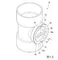
また或いは、図12に示すように、摘まみ部50は、上記した実施形態の摘まみ部26,26に代えて、矢印方向に視て(すなわち摘まみ部50の突出方向から見て)偏平な筒状に形成され、先端が扁平なレンチ等の工具(図13参照)60を内空(工具挿入部)Sに挿入して蓋体20を開閉可能に形成したものであってもよい。
Alternatively, as shown in FIG. 12, the
この場合、例えば摘まみ部50の先端50aに第2の切欠51,51を形成することができる。このように第2の切欠51,51を形成することで、フランジ部23に形成した切欠41,41に嵌合させる工具等よりも短尺な工具を嵌合させて蓋体20を回転させることも可能となる。なお、第2の切欠51,51は、フランジ部23の中心を通る直径上に形成されていることが好ましい。
In this case, for example, the
また、摘まみ部50は、フランジ部23よりも突出寸法が小さく形成されていてもよいし、先端50aがフランジ部23の端面23aとほぼ同一面上に形成されていてもよい。
摘まみ部50の長手方向が水平方向に向けられているとともに、第2の切欠51,51が切欠41,41と同一径上に形成されており、かつ、摘まみ部50の先端50aがフランジ部23と略同一面上に形成されていてもよい。この場合、切欠41,41と第2の切欠51,51のいずれか又は全てに蓋体20を回転させる棒状部材を嵌合させることが可能となる。
Further, the
The longitudinal direction of the
また、図12,図14又は図15に示すように、蓋体20と掃除口部13のそれぞれには、図15に示すボールチェーン等の紐状部材55を挿通可能な通し孔56,57が形成されているとよい。
蓋体20において、通し孔56は、切欠41,41に棒状部材を嵌合させて蓋体20を回転させる際に邪魔ないならないように蓋体20の下方寄りの位置に形成されているとよい。
As shown in FIG. 12, FIG. 14 or FIG. 15, through
In the
掃除口部13において、通し孔57は、掃除口部13の下方側、好ましくは最下位置に形成されているとよい。
このように通し孔56,57を形成することで、蓋体20を掃除口部13から取り外した際に、掃除口部13の下方に蓋体20を吊下させておくことができ、閉塞板24の管路側の面が汚れた蓋材20の置き場に困ることがなくなるという効果が得られる。また、蓋体20を誤って落としてしまうということを防止することができる。
In the cleaning
By forming the through
また、通し孔56,57を上記した位置に形成することで、蓋体20を掃除口部13から取り外した際に、蓋体20が掃除口部13の下方に吊下するため、蓋体20が排管のメンテナンスの邪魔になることを防止することができるという効果が得られる。
Further, by forming the through
これ以外にも、本発明の主旨を逸脱しない限り、上記実施の形態で挙げた構成を取捨選択したり、他の構成に適宜変更したりすることが可能である。 In addition to this, the configuration described in the above embodiment can be selected or changed to another configuration as appropriate without departing from the gist of the present invention.
10 掃除口継手
12p パイプ接続部
13 掃除口部
15 係合溝
20 蓋体
21 挿入筒部(挿入部)
23 フランジ部
27 係合突起
40 工具係合溝
41 切欠き部
42 立ち上がり壁
50 摘まみ部
56 通し孔
57 通し孔
S 内空(工具挿入部)
DESCRIPTION OF
23
Claims (6)
前記挿入部の一端から径方向外方に延びるよう形成された環状のフランジ部と、
前記挿入部の中心軸周りに回転させることによって前記掃除口部に形成された複数の係合溝に係合される複数の係合突起と、
前記フランジ部において、前記フランジ部の中心を挟んだ両側に形成された一対の工具係合溝と、を備えることを特徴とする掃除口継手の蓋体。 An insertion portion to be inserted into the cleaning port portion;
An annular flange portion formed to extend radially outward from one end of the insertion portion;
A plurality of engagement protrusions engaged with a plurality of engagement grooves formed in the cleaning port by rotating around the central axis of the insertion portion;
The said flange part is provided with a pair of tool engaging groove formed in the both sides which pinched | interposed the center of the said flange part, The cover body of a cleaning-mouth-joint characterized by the above-mentioned.
前記摘まみ部の内空が工具挿入部であることを特徴とする請求項1から3のいずれか1項に記載の掃除口継手の蓋体。 On the inside of the flange portion, a knob portion formed in a flat cylindrical shape is formed,
The interior of the said knob | pick part is a tool insertion part, The cover body of the cleaning mouth joint of any one of Claim 1 to 3 characterized by the above-mentioned.
前記継手本体の前記掃除口部に装着可能な請求項1から3のいずか一項に記載の蓋体と、
を備えることを特徴とする掃除口継手。 A joint main body having a pipe connecting portion to which pipes are connected to both ends, and a cleaning port portion formed between the pipe connecting portions,
The lid according to any one of claims 1 to 3, attachable to the cleaning port of the joint body,
A cleaning mouth joint comprising:
Priority Applications (1)
| Application Number | Priority Date | Filing Date | Title |
|---|---|---|---|
| JP2015017841A JP6651289B2 (en) | 2014-03-31 | 2015-01-30 | Lid of cleaning port joint and cleaning port coupling |
Applications Claiming Priority (3)
| Application Number | Priority Date | Filing Date | Title |
|---|---|---|---|
| JP2014074007 | 2014-03-31 | ||
| JP2014074007 | 2014-03-31 | ||
| JP2015017841A JP6651289B2 (en) | 2014-03-31 | 2015-01-30 | Lid of cleaning port joint and cleaning port coupling |
Related Child Applications (1)
| Application Number | Title | Priority Date | Filing Date |
|---|---|---|---|
| JP2020007760A Division JP6748315B2 (en) | 2014-03-31 | 2020-01-21 | Cleaning mouth joint lid and cleaning mouth joint |
Publications (2)
| Publication Number | Publication Date |
|---|---|
| JP2015200405A true JP2015200405A (en) | 2015-11-12 |
| JP6651289B2 JP6651289B2 (en) | 2020-02-19 |
Family
ID=54551833
Family Applications (3)
| Application Number | Title | Priority Date | Filing Date |
|---|---|---|---|
| JP2015017841A Active JP6651289B2 (en) | 2014-03-31 | 2015-01-30 | Lid of cleaning port joint and cleaning port coupling |
| JP2020007760A Active JP6748315B2 (en) | 2014-03-31 | 2020-01-21 | Cleaning mouth joint lid and cleaning mouth joint |
| JP2020133156A Active JP7128238B2 (en) | 2014-03-31 | 2020-08-05 | cleaning spout fitting |
Family Applications After (2)
| Application Number | Title | Priority Date | Filing Date |
|---|---|---|---|
| JP2020007760A Active JP6748315B2 (en) | 2014-03-31 | 2020-01-21 | Cleaning mouth joint lid and cleaning mouth joint |
| JP2020133156A Active JP7128238B2 (en) | 2014-03-31 | 2020-08-05 | cleaning spout fitting |
Country Status (1)
| Country | Link |
|---|---|
| JP (3) | JP6651289B2 (en) |
Cited By (8)
| Publication number | Priority date | Publication date | Assignee | Title |
|---|---|---|---|---|
| JP6029197B1 (en) * | 2016-03-01 | 2016-11-24 | 株式会社大和精機 | Cable protector |
| JP2017115386A (en) * | 2015-12-24 | 2017-06-29 | 株式会社クボタケミックス | Pipe joint with cleaning opening |
| JP2018025073A (en) * | 2016-08-12 | 2018-02-15 | 株式会社ブリヂストン | Joint, and drainage system |
| JP2019007306A (en) * | 2017-06-28 | 2019-01-17 | 積水化学工業株式会社 | Joint |
| JP2019060456A (en) * | 2017-09-28 | 2019-04-18 | 積水化学工業株式会社 | Cleaning port joint |
| JP2019060457A (en) * | 2017-09-28 | 2019-04-18 | 積水化学工業株式会社 | Cleaning port joint |
| JP2019215065A (en) * | 2018-06-14 | 2019-12-19 | 前澤化成工業株式会社 | Pipe joint |
| JP2020186817A (en) * | 2014-03-31 | 2020-11-19 | 積水化学工業株式会社 | Cleaning port joint |
Citations (8)
| Publication number | Priority date | Publication date | Assignee | Title |
|---|---|---|---|---|
| US4393900A (en) * | 1981-11-25 | 1983-07-19 | General Signal Corporation | Insert plug |
| JPS58159258U (en) * | 1982-04-17 | 1983-10-24 | エツチ・アンド・ケ−株式会社 | Composite protective cap for the threaded end of the steel pipe unit |
| JP2001158448A (en) * | 1999-11-30 | 2001-06-12 | Yoshino Kogyosho Co Ltd | Tube container made of synthetic resin |
| JP2005076265A (en) * | 2003-08-29 | 2005-03-24 | Sekisui Chem Co Ltd | Cleaning port for drain pipe |
| JP2005226397A (en) * | 2004-02-16 | 2005-08-25 | Noriatsu Kojima | Clean out structure of piping |
| JP2005248491A (en) * | 2004-03-02 | 2005-09-15 | Kubota Corp | Joint for inner sub-pipe |
| JP2007309047A (en) * | 2006-05-22 | 2007-11-29 | Maezawa Kasei Ind Co Ltd | Cover loss preventive member and its manufacturing method |
| JP2013170428A (en) * | 2012-02-22 | 2013-09-02 | Lixil Corp | Lid and drain trap |
Family Cites Families (8)
| Publication number | Priority date | Publication date | Assignee | Title |
|---|---|---|---|---|
| EP0119289A1 (en) * | 1983-03-21 | 1984-09-26 | Hans Dr. Sallhofer | Pipe sleeve for pipelines with access supports closable by lids |
| JP3065464U (en) * | 1999-07-05 | 2000-02-02 | 有限会社 丸昌工業 | Elbow for piping |
| JP2002188192A (en) * | 2000-12-21 | 2002-07-05 | Noriatsu Kojima | Cleaning hole of drainage path |
| DE20022107U1 (en) * | 2000-12-30 | 2001-03-01 | Rehau Ag & Co | Device for use in exhaust systems |
| JP5016375B2 (en) * | 2007-05-18 | 2012-09-05 | アロン化成株式会社 | Full water test fitting |
| CN202401539U (en) * | 2011-12-27 | 2012-08-29 | 绍兴市同正塑胶管业有限公司 | Pressure-bearing standpipe inspection hole |
| US8733404B2 (en) * | 2012-09-04 | 2014-05-27 | Protective Industries, Inc. | Threaded plug for hammer union and assembly thereof |
| JP6651289B2 (en) * | 2014-03-31 | 2020-02-19 | 積水化学工業株式会社 | Lid of cleaning port joint and cleaning port coupling |
-
2015
- 2015-01-30 JP JP2015017841A patent/JP6651289B2/en active Active
-
2020
- 2020-01-21 JP JP2020007760A patent/JP6748315B2/en active Active
- 2020-08-05 JP JP2020133156A patent/JP7128238B2/en active Active
Patent Citations (8)
| Publication number | Priority date | Publication date | Assignee | Title |
|---|---|---|---|---|
| US4393900A (en) * | 1981-11-25 | 1983-07-19 | General Signal Corporation | Insert plug |
| JPS58159258U (en) * | 1982-04-17 | 1983-10-24 | エツチ・アンド・ケ−株式会社 | Composite protective cap for the threaded end of the steel pipe unit |
| JP2001158448A (en) * | 1999-11-30 | 2001-06-12 | Yoshino Kogyosho Co Ltd | Tube container made of synthetic resin |
| JP2005076265A (en) * | 2003-08-29 | 2005-03-24 | Sekisui Chem Co Ltd | Cleaning port for drain pipe |
| JP2005226397A (en) * | 2004-02-16 | 2005-08-25 | Noriatsu Kojima | Clean out structure of piping |
| JP2005248491A (en) * | 2004-03-02 | 2005-09-15 | Kubota Corp | Joint for inner sub-pipe |
| JP2007309047A (en) * | 2006-05-22 | 2007-11-29 | Maezawa Kasei Ind Co Ltd | Cover loss preventive member and its manufacturing method |
| JP2013170428A (en) * | 2012-02-22 | 2013-09-02 | Lixil Corp | Lid and drain trap |
Cited By (12)
| Publication number | Priority date | Publication date | Assignee | Title |
|---|---|---|---|---|
| JP2020186817A (en) * | 2014-03-31 | 2020-11-19 | 積水化学工業株式会社 | Cleaning port joint |
| JP2017115386A (en) * | 2015-12-24 | 2017-06-29 | 株式会社クボタケミックス | Pipe joint with cleaning opening |
| JP6029197B1 (en) * | 2016-03-01 | 2016-11-24 | 株式会社大和精機 | Cable protector |
| JP2017158279A (en) * | 2016-03-01 | 2017-09-07 | 株式会社大和精機 | Cable protector |
| JP2018025073A (en) * | 2016-08-12 | 2018-02-15 | 株式会社ブリヂストン | Joint, and drainage system |
| JP2019007306A (en) * | 2017-06-28 | 2019-01-17 | 積水化学工業株式会社 | Joint |
| JP7025143B2 (en) | 2017-06-28 | 2022-02-24 | 積水化学工業株式会社 | Fittings |
| JP2019060456A (en) * | 2017-09-28 | 2019-04-18 | 積水化学工業株式会社 | Cleaning port joint |
| JP2019060457A (en) * | 2017-09-28 | 2019-04-18 | 積水化学工業株式会社 | Cleaning port joint |
| JP7084119B2 (en) | 2017-09-28 | 2022-06-14 | 積水化学工業株式会社 | Cleaning port fitting |
| JP2019215065A (en) * | 2018-06-14 | 2019-12-19 | 前澤化成工業株式会社 | Pipe joint |
| JP7227706B2 (en) | 2018-06-14 | 2023-02-22 | 前澤化成工業株式会社 | pipe joint |
Also Published As
| Publication number | Publication date |
|---|---|
| JP6748315B2 (en) | 2020-08-26 |
| JP2020073824A (en) | 2020-05-14 |
| JP2020186817A (en) | 2020-11-19 |
| JP7128238B2 (en) | 2022-08-30 |
| JP6651289B2 (en) | 2020-02-19 |
Similar Documents
| Publication | Publication Date | Title |
|---|---|---|
| JP2015200405A (en) | Lid body of cleaning hole joint, and cleaning hole joint | |
| JP6139438B2 (en) | Opening / closing operation valve operation fixture | |
| CN210716465U (en) | Butterfly valve mounting structure | |
| US20160303719A1 (en) | Oil filter removal tool | |
| US20160325417A1 (en) | Oil filter removal tool | |
| KR101486939B1 (en) | Plug for sealing gas pipe | |
| JP2007170630A (en) | Check valve mounting structure | |
| JP2009028846A (en) | Valve handle | |
| JP2015132201A (en) | drain plug | |
| JP2010195460A (en) | Lid opening and closing tool for drum can | |
| JP2015120095A (en) | Fine iron powder removal device | |
| JP2015081615A (en) | Universal adapter with gas cock | |
| TW200500172A (en) | Improved tool structure | |
| JP2004360713A (en) | Gas cock | |
| JP2009192037A (en) | Ball-lift type check valve | |
| JP2002235861A (en) | Valve | |
| JP3842028B2 (en) | Stopcock device | |
| JP2004251346A (en) | Pipe joint | |
| JP5597561B2 (en) | Bath circulator | |
| US20060082134A1 (en) | Pipe tool | |
| JP6457367B2 (en) | Container with open / close lid | |
| JP2009066704A (en) | Metal hook mounting bit | |
| KR200436364Y1 (en) | Hexagonal wrench | |
| JP5887213B2 (en) | Cap operation tool | |
| JP2009058070A (en) | Piping nut |
Legal Events
| Date | Code | Title | Description |
|---|---|---|---|
| A621 | Written request for application examination |
Free format text: JAPANESE INTERMEDIATE CODE: A621 Effective date: 20180104 |
|
| A977 | Report on retrieval |
Free format text: JAPANESE INTERMEDIATE CODE: A971007 Effective date: 20181012 |
|
| A131 | Notification of reasons for refusal |
Free format text: JAPANESE INTERMEDIATE CODE: A131 Effective date: 20181023 |
|
| A521 | Request for written amendment filed |
Free format text: JAPANESE INTERMEDIATE CODE: A523 Effective date: 20181221 |
|
| A131 | Notification of reasons for refusal |
Free format text: JAPANESE INTERMEDIATE CODE: A131 Effective date: 20190528 |
|
| A521 | Request for written amendment filed |
Free format text: JAPANESE INTERMEDIATE CODE: A523 Effective date: 20190726 |
|
| TRDD | Decision of grant or rejection written | ||
| A01 | Written decision to grant a patent or to grant a registration (utility model) |
Free format text: JAPANESE INTERMEDIATE CODE: A01 Effective date: 20191224 |
|
| A61 | First payment of annual fees (during grant procedure) |
Free format text: JAPANESE INTERMEDIATE CODE: A61 Effective date: 20200122 |
|
| R150 | Certificate of patent or registration of utility model |
Ref document number: 6651289 Country of ref document: JP Free format text: JAPANESE INTERMEDIATE CODE: R150 |