JP2015199417A - webbing take-up device - Google Patents

webbing take-up device Download PDF

Info

Publication number
JP2015199417A
JP2015199417A JP2014078895A JP2014078895A JP2015199417A JP 2015199417 A JP2015199417 A JP 2015199417A JP 2014078895 A JP2014078895 A JP 2014078895A JP 2014078895 A JP2014078895 A JP 2014078895A JP 2015199417 A JP2015199417 A JP 2015199417A
Authority
JP
Japan
Prior art keywords
spool
stopper
lock base
guide member
webbing
Prior art date
Legal status (The legal status is an assumption and is not a legal conclusion. Google has not performed a legal analysis and makes no representation as to the accuracy of the status listed.)
Pending
Application number
JP2014078895A
Other languages
Japanese (ja)
Inventor
顕司 福田
Kenji Fukuda
顕司 福田
Current Assignee (The listed assignees may be inaccurate. Google has not performed a legal analysis and makes no representation or warranty as to the accuracy of the list.)
Tokai Rika Co Ltd
Original Assignee
Tokai Rika Co Ltd
Priority date (The priority date is an assumption and is not a legal conclusion. Google has not performed a legal analysis and makes no representation as to the accuracy of the date listed.)
Filing date
Publication date
Application filed by Tokai Rika Co Ltd filed Critical Tokai Rika Co Ltd
Priority to JP2014078895A priority Critical patent/JP2015199417A/en
Publication of JP2015199417A publication Critical patent/JP2015199417A/en
Pending legal-status Critical Current

Links

Images

Abstract

PROBLEM TO BE SOLVED: To provide a webbing take-up device capable of increasing strength of a stopper and guide means against tension of webbing.SOLUTION: When webbing is pulled out in a state in which rotation of a lock base 40 is inhibited in an emergency of a vehicle, a spool 18 is rotated relative to the lock base 40, and an energy absorption member is deformed. Since a stopper 76 for limiting the amount of rotation of the spool 18 is engaged with an inner peripheral part of the guide member 66, strength of this engagement part can be increased.

Description

本発明は、ロックベースに対するスプールの引出方向の回転をストッパによって阻止できるウェビング巻取装置に関する。   The present invention relates to a webbing take-up device that can prevent rotation of a spool in a pull-out direction with respect to a lock base by a stopper.

ストッパのスプール中心軸線側の部分に形成された雌ねじがロックベースに形成された雄ねじに螺合したウェビング巻取装置がある(一例として、下記特許文献1を参照)。ロック機構及びフォースリミッタ機構が作動されて、ストッパがスプールと共に引出方向へ回転されると、ストッパがロックベースの雄ねじに案内されてロックベースへ接近移動される。ストッパがロックベースに当接されて接近移動が阻止されることによってスプールの引出方向への回転が阻止される。このような構成では、ロックベースの回転阻止状態でウェビングが引張られると、ストッパの雌ねじはロックベースの雄ねじから軸力を受ける。このような軸力に対する雄ねじ及び雌ねじの強度を高めるためにストッパの雌ねじ及びロックベースの雄ねじのねじ径を大きくすると、ストッパが大型化する。   There is a webbing take-up device in which a female screw formed on a portion on the spool central axis side of a stopper is screwed with a male screw formed on a lock base (see Patent Document 1 below as an example). When the lock mechanism and the force limiter mechanism are operated and the stopper is rotated in the pulling direction together with the spool, the stopper is guided by the male screw of the lock base and moved closer to the lock base. The stopper is brought into contact with the lock base to prevent the approaching movement, thereby preventing the spool from rotating in the pulling-out direction. In such a configuration, when the webbing is pulled while the lock base is prevented from rotating, the female screw of the stopper receives an axial force from the male screw of the lock base. When the screw diameters of the female screw of the stopper and the male screw of the lock base are increased in order to increase the strength of the male screw and the female screw against such an axial force, the stopper is enlarged.

特開平11−157416号公報JP-A-11-157416

本発明は、上記事実を考慮して、ストッパを特に大型化することなく、ウェビングの引張りに対するストッパ及びガイド手段の強度を向上できるウェビング巻取装置を得ることが目的である。   An object of the present invention is to obtain a webbing take-up device that can improve the strength of the stopper and guide means against webbing tension without particularly increasing the size of the stopper in consideration of the above facts.

請求項1に記載のウェビング巻取装置は、ウェビングが引出されることによって引出方向へ回転するスプールと、前記スプールと一体に回転可能に設けられ、車両緊急時に引出方向への回転が制限されるロックベースと、前記車両緊急時に前記スプールが前記ロックベースに対して引出方向に相対回転されることによって変形されて前記スプールの回転力を吸収するエネルギー吸収部材と、前記相対回転によって移動端へ向けて移動可能とされると共に、前記移動端で前記相対回転を阻止するストッパと、前記ストッパに径方向外側から係合し、前記相対回転によって前記ストッパを前記移動端側へ移動させるガイド手段と、を備えている。   The webbing take-up device according to claim 1 is provided so as to rotate integrally with the spool that rotates in the pull-out direction when the webbing is pulled out, and the rotation in the pull-out direction is restricted in the event of a vehicle emergency. A lock base, an energy absorbing member that absorbs the rotational force of the spool by being deformed by rotating the spool relative to the lock base in the pull-out direction in an emergency of the vehicle, and toward the moving end by the relative rotation A stopper that prevents the relative rotation at the moving end, and a guide means that engages the stopper from the outside in the radial direction and moves the stopper toward the moving end by the relative rotation; It has.

請求項1に記載のウェビング巻取装置では、ガイド手段が外側からストッパに係合される。このため、ストッパを特に大型化することなく、ガイド手段やストッパの回転中心からガイド手段とストッパとの係合部分までの長さを大きくできる。これによって、ストッパが移動された際にガイド手段とストッパとの係合部分に作用する単位面積当たりの荷重が低減され、強度を向上できる。   In the webbing take-up device according to the first aspect, the guide means is engaged with the stopper from the outside. For this reason, the length from the rotation center of the guide means or the stopper to the engaging portion between the guide means and the stopper can be increased without particularly increasing the size of the stopper. Thereby, when the stopper is moved, the load per unit area acting on the engaging portion between the guide means and the stopper is reduced, and the strength can be improved.

請求項2に記載のウェビング巻取装置は、請求項1に記載のウェビング巻取装置において、前記ガイド手段は、前記ストッパに形成された雄ねじに螺合される雌ねじとされている。   A webbing take-up device according to a second aspect is the webbing take-up device according to the first aspect, wherein the guide means is a female screw that is screwed into a male screw formed in the stopper.

請求項2に記載のウェビング巻取装置では、ガイド手段が雌ねじとされて、ストッパに形成された雄ねじにスプール回転半径方向外側から螺合される。このため、スプールの雄ねじと雌ねじとの螺合部分までの長さ(ねじ径)を大きくでき、雄ねじに対して雌ねじが回転された際に雌ねじから雄ねじに付与される単位面積当たりの軸力を低減できる。これによって、ストッパを大きくすることなくロックベースの回転阻止状態でのウェビングの引張りに対するねじ部の強度を向上できる。   In the webbing take-up device according to the second aspect, the guide means is a female screw and is screwed into the male screw formed on the stopper from the outside in the radial direction of the spool rotation. For this reason, the length (screw diameter) to the threaded part of the male screw and female screw of the spool can be increased, and the axial force per unit area applied from the female screw to the male screw when the female screw is rotated relative to the male screw. Can be reduced. Thereby, the strength of the threaded portion against the webbing tension in the lock base rotation prevention state can be improved without increasing the stopper.

請求項3に記載のウェビング巻取装置は、請求項1又は請求項2に記載のウェビング巻取装置において、前記ガイド手段が形成され、前記スプール及び前記ロックベースの一方とは別体で構成されて前記一方に相対回転不能に設けられると共に、前記一方よりも機械的強度が高く設定されたガイド部材を備えている。   The webbing take-up device according to a third aspect is the webbing take-up device according to the first or second aspect, wherein the guide means is formed and is configured separately from one of the spool and the lock base. And a guide member which is provided on the one side so as not to be relatively rotatable and has a mechanical strength higher than that of the one side.

請求項3に記載のウェビング巻取装置では、ガイド部材にガイド手段が形成され、このガイド部材がスプール及びロックベースの一方に相対回転不能に設けられる。ここで、ガイド部材の機械的強度は、前記一方よりも高く設定される。このため、前記一方の機械的強度を特に高く設定しなくても、ガイド部材がストッパから受ける荷重に対する機械的強度を確保できる。   In the webbing take-up device according to a third aspect of the present invention, guide means is formed on the guide member, and the guide member is provided on one of the spool and the lock base so as not to be relatively rotatable. Here, the mechanical strength of the guide member is set higher than the one. For this reason, even if the one mechanical strength is not set to be particularly high, the mechanical strength against the load received by the guide member from the stopper can be ensured.

請求項4に記載のウェビング巻取装置は、請求項3に記載のウェビング巻取装置において、前記ガイド部材と前記スプール及び前記ロックベースの一方との間で回転力を伝達して前記ガイド部材の前記一方に対する相対回転を阻止する複数の回転力伝達部を備えている。   The webbing take-up device according to a fourth aspect is the webbing take-up device according to the third aspect, wherein a rotational force is transmitted between the guide member and one of the spool and the lock base. A plurality of rotational force transmitting portions that prevent relative rotation with respect to the one side are provided.

請求項4に記載のウェビング巻取装置は、複数の回転力伝達部を備えている。このため、ガイド部材とスプール及びロックベースの一方との間で回転力が伝達される際に、この回転力が複数の回転力伝達部にそれぞれ分散される。これによって、ガイド部材とスプール及びロックベースの一方との間で回転力が伝達される際の応力集中を抑制できる。なお、抑制とは単に抑えるのみでなく、阻止する場合を含む意味として、この明細書全体を通して用いる。   According to a fourth aspect of the present invention, there is provided a webbing take-up device including a plurality of rotational force transmission units. For this reason, when the rotational force is transmitted between the guide member and one of the spool and the lock base, the rotational force is distributed to the plurality of rotational force transmission units. Thereby, the stress concentration when the rotational force is transmitted between the guide member and one of the spool and the lock base can be suppressed. It should be noted that the term “suppression” is used not only to suppress but also to prevent, throughout this specification.

請求項5に記載のウェビング巻取装置は、請求項1から請求項4の何れか1項に記載のウェビング巻取装置において、前記ストッパは、外周部に前記ガイド手段が係合する円板状に形成されている。   The webbing take-up device according to claim 5 is the webbing take-up device according to any one of claims 1 to 4, wherein the stopper is a disc-shaped member that engages the guide means with an outer peripheral portion. Is formed.

請求項5に記載のウェビング巻取装置では、円板形状のストッパの外周部にガイド手段が係合され、ストッパはガイド手段から中央側の荷重を受ける。このため、ストッパの中央側でガイド手段からストッパ径方向外側の荷重を受けるような構成に比べて、ガイド手段とストッパとの係合部分に作用する単位面積当たりの荷重を低減できる。なお、円板状とは内側に孔が形成されて環状となった場合をも含む意味として、この明細書全体を通して用いる。   In the webbing take-up device according to the fifth aspect, the guide means is engaged with the outer peripheral portion of the disc-shaped stopper, and the stopper receives a load on the center side from the guide means. For this reason, the load per unit area which acts on the engaging part of a guide means and a stopper can be reduced compared with the structure which receives the load of the stopper radial direction outer side from a guide means in the center side of a stopper. In addition, disk shape is used throughout this specification as the meaning including the case where a hole is formed inside and it becomes cyclic | annular.

以上説明したように、本発明に係るウェビング巻取装置では、ストッパを特に大型化することなく、ウェビングの引張りに対するストッパ及びガイド手段の強度を向上できる。   As described above, in the webbing take-up device according to the present invention, the strength of the stopper and the guide means against the webbing tension can be improved without particularly increasing the size of the stopper.

本実施の形態に係るウェビング巻取装置の分解斜視図である。It is a disassembled perspective view of the webbing take-up device according to the present embodiment. スプール、ロックベース、ガイド部材、ストッパの拡大分解斜視図である。It is an expansion exploded perspective view of a spool, a lock base, a guide member, and a stopper. 図2の3−3線に沿った断面で、(A)はストッパの初期状態を示し、(B)はストッパがスプール軸方向に移動された状態を示している。2, (A) shows the initial state of the stopper, and (B) shows the state in which the stopper has been moved in the spool axis direction.

次に、本発明の一実施の形態を図1から図3に基づいて説明する。なお、各図において矢印FRはウェビング巻取装置10の前側を示し、矢印LHは左側を示し、矢印UPは上側を示す。   Next, an embodiment of the present invention will be described with reference to FIGS. In each figure, the arrow FR indicates the front side of the webbing take-up device 10, the arrow LH indicates the left side, and the arrow UP indicates the upper side.

<本実施の形態の構成>
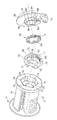
図1に示されるように、本実施の形態に係るウェビング巻取装置10は、車両のリヤシートの後側で車両の骨格部材や補強部材に固定されるフレーム12を備えている。フレーム12は左右方向に対向する壁部14、16を備えており、壁部14と壁部16との間にはスプール18が設けられている。スプール18の軸方向は左右方向に沿っており、スプール18には中心軸線に沿って貫通孔20が形成されている。スプール18にはウェビング22の長手方向基端側が係止されており、スプール18が軸周りに巻取方向に回転されることによって、ウェビング22がスプール18の外周部に層状に巻取られる。また、スプール18の左側には回転部材24が設けられている。回転部材24は、スプール18の左側から貫通孔20に嵌挿されており、これによって、回転部材24のスプール18に対する相対回転が阻止されている。
<Configuration of the present embodiment>
As shown in FIG. 1, a webbing retractor 10 according to the present embodiment includes a frame 12 that is fixed to a skeleton member or a reinforcing member of a vehicle on the rear side of the rear seat of the vehicle. The frame 12 includes wall portions 14 and 16 that face in the left-right direction, and a spool 18 is provided between the wall portion 14 and the wall portion 16. The axial direction of the spool 18 is along the left-right direction, and a through hole 20 is formed in the spool 18 along the central axis. The spool 18 is engaged with the proximal end side in the longitudinal direction of the webbing 22, and the webbing 22 is wound around the outer periphery of the spool 18 in layers by rotating the spool 18 around the axis in the winding direction. A rotating member 24 is provided on the left side of the spool 18. The rotating member 24 is fitted into the through hole 20 from the left side of the spool 18, thereby preventing relative rotation of the rotating member 24 with respect to the spool 18.

一方、フレーム12の左側には、車両衝突時等の車両緊急時に作動するプリテンショナ26が設けられている。プリテンショナ26が作動されることによって、回転部材24が巻取方向に回転される。これによって、スプール18が巻取方向に回転されて、ウェビング22がスプール18に巻取られる。また、プリテンショナ26の左側にはスプリングハウジング28が設けられており、回転部材24がスプリングハウジング28に回転自在に支持されている。スプリングハウジング28内には、渦巻きばね(図示省略)が設けられている。渦巻きばねは、回転部材24に係合されており、これによって、スプール18が巻取方向へ付勢されている。   On the other hand, on the left side of the frame 12, a pretensioner 26 that operates in the event of a vehicle emergency such as a vehicle collision is provided. When the pretensioner 26 is operated, the rotating member 24 is rotated in the winding direction. As a result, the spool 18 is rotated in the winding direction, and the webbing 22 is wound on the spool 18. A spring housing 28 is provided on the left side of the pretensioner 26, and the rotating member 24 is rotatably supported by the spring housing 28. A spiral spring (not shown) is provided in the spring housing 28. The spiral spring is engaged with the rotating member 24, and thereby the spool 18 is urged in the winding direction.

一方、スプール18の貫通孔20の内側には、エネルギー吸収部材としてのトーションシャフト30が設けられている。トーションシャフト30は軸部32を備えており、軸部32の左側には連結部34が形成されている。また、軸部32の右側には連結部36が形成されており、更に、連結部36の右側には支持軸38がスプール18に対して同軸上に突出形成されている。トーションシャフト30の左側の連結部34は、スプール18の貫通孔20の内側で係合しており、これによって、トーションシャフト30のスプール18に対する相対回転が阻止されている。   On the other hand, a torsion shaft 30 as an energy absorbing member is provided inside the through hole 20 of the spool 18. The torsion shaft 30 includes a shaft portion 32, and a connecting portion 34 is formed on the left side of the shaft portion 32. A connecting portion 36 is formed on the right side of the shaft portion 32, and a support shaft 38 is formed on the right side of the connecting portion 36 so as to protrude coaxially with the spool 18. The connecting portion 34 on the left side of the torsion shaft 30 is engaged inside the through hole 20 of the spool 18, thereby preventing relative rotation of the torsion shaft 30 with respect to the spool 18.

また、スプール18の右側にはロックベース40が設けられている。ロックベース40の左側の端面は、スプール18の右側の端面に当接されており、また、ロックベース40は、トーションシャフト30の右側の連結部36に係合されてトーションシャフト30に対する相対回転が阻止されている。これによって、ロックベース40がスプール18と一体的に回転可能とされている。但し、ロックベース40の回転が阻止された状態で、トーションシャフト30の機械的強度を上回る回転力がスプール18に作用すると、トーションシャフト30の軸部32が捻り変形されながらスプール18が回転される。   A lock base 40 is provided on the right side of the spool 18. The left end surface of the lock base 40 is in contact with the right end surface of the spool 18, and the lock base 40 is engaged with the connecting portion 36 on the right side of the torsion shaft 30 so that the relative rotation with respect to the torsion shaft 30 is performed. It is blocked. As a result, the lock base 40 can rotate integrally with the spool 18. However, when the rotational force exceeding the mechanical strength of the torsion shaft 30 acts on the spool 18 in a state where the rotation of the lock base 40 is blocked, the spool 18 is rotated while the shaft portion 32 of the torsion shaft 30 is twisted and deformed. .

さらに、ロックベース40にはロックパウル42が回動可能に支持されている。ロックパウル42は、フレーム12の右側の壁部16に形成されたラチェット孔44の内側に配置されており、回動されることによってラチェット孔44のラチェット歯に噛合う。これによって、ロックベース40の巻取方向とは反対の引出方向への回転が阻止される。ロックベース40の右側にはセンサ機構46が設けられている。センサ機構46はVギヤ48を備えている。Vギヤ48は外周部にラチェット歯が形成されており、トーションシャフト30の支持軸38に回転自在に支持されている。また、Vギヤ48にはロックパウル42に形成された係合軸50が係合されており、ロックベース40がVギヤ48に対して引出方向に相対回転されることによってロックパウル42が回動されてラチェット孔44のラチェット歯に噛合う。   Further, a lock pawl 42 is rotatably supported on the lock base 40. The lock pawl 42 is disposed inside a ratchet hole 44 formed in the right wall 16 of the frame 12, and meshes with the ratchet teeth of the ratchet hole 44 by rotating. As a result, the lock base 40 is prevented from rotating in the pull-out direction opposite to the winding direction. A sensor mechanism 46 is provided on the right side of the lock base 40. The sensor mechanism 46 includes a V gear 48. The V gear 48 has ratchet teeth formed on the outer periphery thereof, and is rotatably supported on the support shaft 38 of the torsion shaft 30. Further, an engagement shaft 50 formed on the lock pawl 42 is engaged with the V gear 48, and the lock pawl 42 rotates when the lock base 40 is rotated relative to the V gear 48 in the pull-out direction. Then, it meshes with the ratchet teeth of the ratchet hole 44.

また、ロックベース40とVギヤ48との間には、図示しないスプリングが設けられており、ロックベース40と共にスプリングが引出方向へ回転されると、Vギヤ48がスプリングによって引出方向に押圧される。これによって、Vギヤ48はロックベース40に追従して引出方向へ回転される。但し、ロックベース40が引出方向に回転した際にスプリングが弾性変形されることによって、ロックベース40はVギヤ48に対して引出方向に相対回転できる。   Further, a spring (not shown) is provided between the lock base 40 and the V gear 48. When the spring is rotated in the pulling direction together with the lock base 40, the V gear 48 is pressed in the pulling direction by the spring. . As a result, the V gear 48 follows the lock base 40 and rotates in the pull-out direction. However, the spring is elastically deformed when the lock base 40 rotates in the pulling direction, so that the lock base 40 can rotate relative to the V gear 48 in the pulling direction.

一方、センサ機構46は第1カバー52を備えており、Vギヤ48は第1カバー52内に収容されている。第1カバー52の内側には、内歯のラチェット歯がトーションシャフト30の支持軸38に対して同軸上に形成されている。このラチェット歯に対応してVギヤ48にはWSIR機構を構成するWパウル54が揺動可能に支持されている。WSIR機構は、車両衝突時等の車両緊急時にスプール18が所定の大きさ以上の回転加速度で引出方向に回転されることによって作動される。スプール18と共にVギヤ48が所定の大きさ以上の回転加速度で引出方向に回転されると、Wパウル54が揺動されて第1カバー52のラチェット歯に係合される。これによって、Vギヤ48の引出方向への回転が阻止される。   On the other hand, the sensor mechanism 46 includes a first cover 52, and the V gear 48 is accommodated in the first cover 52. Inside the first cover 52, internal ratchet teeth are formed coaxially with the support shaft 38 of the torsion shaft 30. Corresponding to the ratchet teeth, a W pawl 54 constituting a WSIR mechanism is supported on the V gear 48 so as to be swingable. The WSIR mechanism is operated when the spool 18 is rotated in the pull-out direction at a rotational acceleration of a predetermined magnitude or more in a vehicle emergency such as a vehicle collision. When the V gear 48 together with the spool 18 is rotated in the pull-out direction with a rotational acceleration of a predetermined magnitude or more, the W pawl 54 is swung and engaged with the ratchet teeth of the first cover 52. As a result, rotation of the V gear 48 in the pull-out direction is prevented.

さらに、第1カバー52の右側には第2カバー56が設けられており、第1カバー52は第2カバー56の内側に収容されている。トーションシャフト30の支持軸38の先端側は、第1カバー52を貫通して、第2カバー56に回転自在に支持されている。第2カバー56にはVSIR機構を構成する加速度センサ58が設けられており、VSIR機構は車両衝突時等の車両急減速状態で作動される。加速度センサ58は、車両衝突時に慣性で転動する硬球60を備えている。硬球60が転動すると、加速度センサ58のセンサパウル62が硬球60によって押上げられてVギヤ48のラチェット歯に噛合う。これによって、Vギヤ48の引出方向への回転が阻止される。   Further, a second cover 56 is provided on the right side of the first cover 52, and the first cover 52 is accommodated inside the second cover 56. The front end side of the support shaft 38 of the torsion shaft 30 passes through the first cover 52 and is rotatably supported by the second cover 56. The second cover 56 is provided with an acceleration sensor 58 constituting a VSIR mechanism, and the VSIR mechanism is operated in a vehicle rapid deceleration state such as when a vehicle collides. The acceleration sensor 58 includes a hard ball 60 that rolls with inertia in the event of a vehicle collision. When the hard ball 60 rolls, the sensor pawl 62 of the acceleration sensor 58 is pushed up by the hard ball 60 and meshes with the ratchet teeth of the V gear 48. As a result, rotation of the V gear 48 in the pull-out direction is prevented.

一方、図2に示されるように、スプール18に形成された貫通孔20の一端部(右側端部)は拡径されて嵌合部64とされており、嵌合部64にはガイド部材66が嵌挿されている。ガイド部材66はスプール18よりも機械的強度、特に、せん断荷重に対する強度が高い金属材料によって筒形状とされて、ガイド部材66のスプール18軸方向他端(左側端部)には底部68が形成されている。底部68の径方向中央側には円孔70が形成されており、円孔70にはトーションシャフト30が貫通される。   On the other hand, as shown in FIG. 2, one end portion (right end portion) of the through hole 20 formed in the spool 18 is expanded in diameter to form a fitting portion 64, and the fitting portion 64 includes a guide member 66. Is inserted. The guide member 66 has a cylindrical shape made of a metal material having a mechanical strength higher than that of the spool 18, in particular, a strength against a shearing load, and a bottom portion 68 is formed at the other end (left end portion) of the guide member 66 in the axial direction of the spool 18. Has been. A circular hole 70 is formed on the radial center side of the bottom 68, and the torsion shaft 30 passes through the circular hole 70.

ガイド部材66の外周部には回転力伝達部としての複数の凸部72が突出形成されている。これらの凸部72に対応して嵌合部64は回転力伝達部としての複数の凹部74を備えており、ガイド部材66が嵌合部64に嵌挿されると、各凸部72が各凹部74に嵌挿され、これによって、ガイド部材66のスプール18に対する相対回転が阻止される。また、ガイド部材66の内側にはストッパ76が設けられている。ストッパ76は円板状に形成されていると共に、外周部には雄ねじ78が形成されている。これに対して、ガイド部材66の内側面にはガイド手段としての雌ねじ80が形成されており、スプール18と共にガイド部材66が引出方向へ回転された際の回転半径方向外側からストッパ76の雄ねじ78に螺合されている。ガイド部材66がストッパ76に対して引出方向に相対回転されると、ストッパ76がガイド部材66に対してスプール18軸方向他側(左側)へ移動される。   A plurality of convex portions 72 as a rotational force transmitting portion protrude from the outer peripheral portion of the guide member 66. Corresponding to these convex portions 72, the fitting portion 64 includes a plurality of concave portions 74 as rotational force transmitting portions. When the guide member 66 is inserted into the fitting portion 64, each convex portion 72 becomes each concave portion. 74, so that the relative rotation of the guide member 66 with respect to the spool 18 is prevented. A stopper 76 is provided inside the guide member 66. The stopper 76 is formed in a disc shape, and a male screw 78 is formed on the outer peripheral portion. On the other hand, a female thread 80 as a guide means is formed on the inner side surface of the guide member 66, and the male thread 78 of the stopper 76 from the outer side in the rotational radius when the guide member 66 is rotated in the pull-out direction together with the spool 18. Are screwed together. When the guide member 66 is rotated relative to the stopper 76 in the pull-out direction, the stopper 76 is moved to the other side (left side) in the spool 18 axial direction with respect to the guide member 66.

一方、ロックベース40のスプール18側(左側)の面には回転制限手段としての筒部82がロックベース40に対して同軸上に形成されている。本ウェビング巻取装置10の組付状態で、筒部82は嵌合部64の内側でスプール18に対して同軸上に配置される。筒部82の内周形状はトーションシャフト30の右側の連結部36の外周形状と同形状(厳密には連結部36の外周形状よりも僅かに大きな相似形状)とされており、連結部36が筒部82に嵌挿される。これによって、ロックベース40のトーションシャフト30に対する回転が阻止される。   On the other hand, on the surface of the lock base 40 on the spool 18 side (left side), a cylindrical portion 82 as rotation limiting means is formed coaxially with the lock base 40. In the assembled state of the webbing take-up device 10, the cylindrical portion 82 is disposed coaxially with the spool 18 inside the fitting portion 64. The inner peripheral shape of the cylindrical portion 82 is the same shape as the outer peripheral shape of the connecting portion 36 on the right side of the torsion shaft 30 (strictly, a similar shape slightly larger than the outer peripheral shape of the connecting portion 36). The tube portion 82 is inserted. Thereby, the rotation of the lock base 40 relative to the torsion shaft 30 is prevented.

また、筒部82の外周形状は複数の凸部84が周方向に断続的に形成された非円形とされている。ストッパ76には、筒部82の外周形状に対応した孔部86が筒部82に対して同軸上に形成されている。孔部86の内周形状は筒部82の外周形状と同じ形状(厳密には、筒部82の外周形状よりも僅かに小さな相似形状)とされており、筒部82が孔部86を貫通している。このため、ストッパ76のロックベース40に対する相対回転が阻止される。図3(A)に示されるように、ストッパ76は初期状態で筒部82の基端側(ロックベース40側)に配置されると共に、この状態で、ストッパ76の雄ねじ78がガイド部材66の雌ねじ80に螺合している。   Further, the outer peripheral shape of the cylindrical portion 82 is a non-circular shape in which a plurality of convex portions 84 are intermittently formed in the circumferential direction. In the stopper 76, a hole portion 86 corresponding to the outer peripheral shape of the cylindrical portion 82 is formed coaxially with the cylindrical portion 82. The inner peripheral shape of the hole portion 86 is the same shape as the outer peripheral shape of the cylindrical portion 82 (strictly, a similar shape slightly smaller than the outer peripheral shape of the cylindrical portion 82), and the cylindrical portion 82 passes through the hole portion 86. doing. For this reason, relative rotation of the stopper 76 with respect to the lock base 40 is prevented. As shown in FIG. 3A, the stopper 76 is disposed on the proximal end side (the lock base 40 side) of the cylindrical portion 82 in the initial state, and in this state, the male screw 78 of the stopper 76 is attached to the guide member 66. The internal thread 80 is screwed.

<本実施の形態の作用、効果>
次に、本実施の形態の作用並びに効果について説明する。
<Operation and effect of the present embodiment>
Next, the operation and effect of the present embodiment will be described.

本ウェビング巻取装置10では、車両衝突時等の車両緊急時に、乗員の身体に装着されたウェビング22が引張られて、スプール18と共にロックベース40が所定の大きさ以上の回転加速度で引出方向へ回転されると、センサ機構46のWSIR機構が作動される。また、車両衝突による車両の急減速状態では、センサ機構46のVSIR機構が作動される。このように、WSIR機構やVSIR機構が作動されることによって、Vギヤ48の引出方向の回転が阻止される。   In the webbing take-up device 10, in the event of a vehicle emergency such as a vehicle collision, the webbing 22 attached to the occupant's body is pulled, and the lock base 40 together with the spool 18 moves in the pull-out direction with a rotational acceleration greater than a predetermined size. When rotated, the WSIR mechanism of the sensor mechanism 46 is activated. Further, the VSIR mechanism of the sensor mechanism 46 is operated when the vehicle is rapidly decelerated due to a vehicle collision. As described above, the WS gear mechanism and the VSIR mechanism are actuated to prevent the V gear 48 from rotating in the pull-out direction.

この状態で、スプール18と共にロックベース40が引出方向へ回転され、これによって、ロックベース40がVギヤ48に対して引出方向へ相対回転されると、ロックベース40に設けられたロックパウル42が回動される。これによって、ロックパウル42の歯が右側の壁部16のラチェット孔44の内歯に係合されると、ロックベース40の引出方向への回転が阻止されて、スプール18の引出方向への回転が阻止される。これによって、ウェビング22のスプール18からの引出しが阻止される。   In this state, when the lock base 40 is rotated in the pull-out direction together with the spool 18, and the lock base 40 is rotated relative to the V gear 48 in the pull-out direction, the lock pawl 42 provided on the lock base 40 is moved. It is rotated. Accordingly, when the teeth of the lock pawl 42 are engaged with the inner teeth of the ratchet hole 44 of the right wall portion 16, the lock base 40 is prevented from rotating in the pull-out direction, and the spool 18 is rotated in the pull-out direction. Is blocked. As a result, the webbing 22 is prevented from being pulled out from the spool 18.

また、この状態で、スプール18の引出方向への回転力がトーションシャフト30の軸部32の機械的強度を上回ると、軸部32が捻り変形されながらスプール18が引出方向へ回転される。このスプール18の回転量分だけウェビング22がスプール18から引出されると共に、スプール18の回転力のエネルギーの一部がトーションシャフト30の捻り変形に供されて吸収される。   In this state, when the rotational force in the pull-out direction of the spool 18 exceeds the mechanical strength of the shaft portion 32 of the torsion shaft 30, the spool 18 is rotated in the pull-out direction while the shaft portion 32 is twisted. The webbing 22 is pulled out of the spool 18 by the amount of rotation of the spool 18, and part of the energy of the rotational force of the spool 18 is subjected to torsional deformation of the torsion shaft 30 and absorbed.

一方、ロックベース40の回転阻止状態でスプール18が引出方向に回転されることによって、ガイド部材66がストッパ76に対して引出方向へ相対回転される。ストッパ76は筒部82によってロックベース40に対する相対回転が阻止されており、また、ストッパ76の雌ねじ80がガイド部材66の雄ねじ78に螺合されている。このため、ガイド部材66がスプール18と共に引出方向へ回転されると、ストッパ76がスプール18軸方向にガイド部材66の底部68側(左側)へ移動される。   On the other hand, when the spool 18 is rotated in the pull-out direction while the lock base 40 is prevented from rotating, the guide member 66 is rotated relative to the stopper 76 in the pull-out direction. The stopper 76 is prevented from rotating relative to the lock base 40 by the cylindrical portion 82, and the female screw 80 of the stopper 76 is screwed to the male screw 78 of the guide member 66. Therefore, when the guide member 66 is rotated in the pull-out direction together with the spool 18, the stopper 76 is moved to the bottom 68 side (left side) of the guide member 66 in the axial direction of the spool 18.

スプール18がロックベース40に対して引出方向へ所定回数回転されると、図3(B)に示されるように、ストッパ76がガイド部材66の底部68に当接され、これによって、ストッパ76が底部68側への移動端に到達してストッパ76の底部68側への移動が阻止される。ストッパ76の底部68側への移動が阻止されることによって、ガイド部材66は引出方向への回転が阻止される。ガイド部材66はスプール18に対して相対回転不能であるため、これによって、スプール18の引出方向の回転が阻止される。   When the spool 18 is rotated a predetermined number of times in the pull-out direction with respect to the lock base 40, the stopper 76 comes into contact with the bottom 68 of the guide member 66 as shown in FIG. The movement to the bottom 68 side is reached and the stopper 76 is prevented from moving to the bottom 68 side. By preventing the stopper 76 from moving toward the bottom 68, the guide member 66 is prevented from rotating in the pull-out direction. Since the guide member 66 cannot rotate relative to the spool 18, this prevents the spool 18 from rotating in the pull-out direction.

ここで、本実施の形態では、雄ねじ78がストッパ76の外周部に形成されて、雌ねじ80がガイド部材66の内側面に形成される。このため、雌ねじがストッパの内側面に形成されて、ストッパにおけるスプール径方向中央側に雄ねじが設けられる構成に比べて、ストッパ76を大型化することなく雄ねじ78及び雌ねじ80のねじ径を大きくできる。これによって、雄ねじ78と雌ねじ80との接触面積を大きくでき、ストッパ76の雄ねじ78がガイド部材66の雌ねじ80から受ける単位面積当たりの軸力を低減できる。   Here, in the present embodiment, the male screw 78 is formed on the outer peripheral portion of the stopper 76, and the female screw 80 is formed on the inner surface of the guide member 66. For this reason, the screw diameters of the male screw 78 and the female screw 80 can be increased without increasing the size of the stopper 76 as compared with a configuration in which the female screw is formed on the inner side surface of the stopper and the male screw is provided on the center side in the spool radial direction of the stopper. . As a result, the contact area between the male screw 78 and the female screw 80 can be increased, and the axial force per unit area received by the male screw 78 of the stopper 76 from the female screw 80 of the guide member 66 can be reduced.

更に詳細に言うと、ストッパ76の底部68側への移動阻止状態でスプール18に引出方向の回転力が作用すると、ストッパ76の雄ねじ78及びガイド部材66の雌ねじ80の各ねじ山には軸方向のせん断荷重が作用される。ここで、本実施の形態では、雄ねじ78と雌ねじ80との接触面積を大きくできるため、雄ねじ78及び雌ねじ80の各ねじ山に作用される単位面積当たりのせん断荷重を小さくできる。これによって、ロックベース40の回転阻止状態でのウェビング22の引張りに対する雄ねじ78及び雌ねじ80の強度を向上できる。   More specifically, when a rotational force in the pull-out direction acts on the spool 18 in a state in which the stopper 76 is prevented from moving toward the bottom 68, each screw thread of the male screw 78 of the stopper 76 and the female screw 80 of the guide member 66 is axially applied. The shear load is applied. Here, in the present embodiment, since the contact area between the male screw 78 and the female screw 80 can be increased, the shear load per unit area applied to each thread of the male screw 78 and the female screw 80 can be reduced. Thereby, the strength of the male screw 78 and the female screw 80 against the tension of the webbing 22 when the lock base 40 is prevented from rotating can be improved.

また、ガイド部材66は、スプール18とは別体で構成され、しかも、ガイド部材66のせん断荷重に対する機械的強度はスプール18よりも高い。これによっても、ストッパ76の底部68側への移動阻止状態でスプール18に引出方向の回転力が作用した際のガイド部材66の雌ねじ80の変形を抑制でき、ストッパ76は円滑にスプール18軸方向へ移動できる。   Further, the guide member 66 is configured separately from the spool 18, and the mechanical strength of the guide member 66 against the shear load is higher than that of the spool 18. This also suppresses deformation of the internal thread 80 of the guide member 66 when a rotational force in the pulling direction acts on the spool 18 in a state where the stopper 76 is prevented from moving toward the bottom 68, and the stopper 76 smoothly moves in the axial direction of the spool 18. Can move to.

さらに、スプール18が回転されると、ガイド部材66の凸部72が凹部74の内側面によって回転方向へ押圧され、これによって、スプール18からガイド部材66へ回転が伝達される。ここで、凸部72はガイド部材66に複数形成され、凹部74はスプール18の嵌合部64に複数形成されるため、スプール18の回転力が各凸部72及び各凹部74に分散される。これによって、ガイド部材66の回転阻止状態でスプール18に引出方向の回転力が付与されても、1つの凸部72や1つの凹部74に荷重が集中することなく、スプール18の回転を効果的に阻止できる。   Further, when the spool 18 is rotated, the convex portion 72 of the guide member 66 is pressed in the rotational direction by the inner surface of the concave portion 74, whereby the rotation is transmitted from the spool 18 to the guide member 66. Here, since a plurality of convex portions 72 are formed on the guide member 66 and a plurality of concave portions 74 are formed on the fitting portions 64 of the spool 18, the rotational force of the spool 18 is distributed to the convex portions 72 and the concave portions 74. . As a result, even if a rotation force in the pulling direction is applied to the spool 18 while the guide member 66 is prevented from rotating, the spool 18 can be effectively rotated without a load being concentrated on one convex portion 72 or one concave portion 74. Can be prevented.

また、ストッパ76がガイド部材66の底部68に当接した状態でスプール18に引出方向の回転力が付与されると、ガイド部材66の雌ねじ80とストッパ76の雄ねじ78との間の軸力の分力によって、ストッパ76が径方向中央側へ変形しようとする。ここで、ストッパ76は、円板状に形成されているため、このような変形を効果的に抑制でき、雌ねじ80と雄ねじ78との螺合を維持できる。   Further, when a rotational force in the pulling direction is applied to the spool 18 in a state where the stopper 76 is in contact with the bottom 68 of the guide member 66, the axial force between the female screw 80 of the guide member 66 and the male screw 78 of the stopper 76 is increased. Due to the component force, the stopper 76 tends to deform toward the radial center. Here, since the stopper 76 is formed in a disk shape, such deformation can be effectively suppressed, and the screwing between the female screw 80 and the male screw 78 can be maintained.

しかも、ストッパ76の孔部86にはロックベース40の筒部82が貫通されている。このため、ストッパ76が径方向中央側へ変形しようとすると、ストッパ76が筒部82によって孔部86の内側から支えられる。これによっても、ストッパ76の変形を効果的に抑制でき、雌ねじ80と雄ねじ78との螺合を維持できる。   Moreover, the cylindrical portion 82 of the lock base 40 is passed through the hole portion 86 of the stopper 76. For this reason, when the stopper 76 is to be deformed toward the center in the radial direction, the stopper 76 is supported by the cylindrical portion 82 from the inside of the hole 86. Also by this, the deformation of the stopper 76 can be effectively suppressed, and the screw engagement between the female screw 80 and the male screw 78 can be maintained.

なお、本実施の形態では、ガイド手段としてのガイド部材66がスプール18に設けられて、回転阻止手段としての筒部82がロックベース40に設けられた構成であった。しかしながら、ガイド手段が外側からストッパに係合する構成であれば、ガイド手段がロックベースに設けられて、回転阻止手段がスプールに設けられる構成であってもよい。   In the present embodiment, the guide member 66 as the guide means is provided on the spool 18, and the cylindrical portion 82 as the rotation prevention means is provided on the lock base 40. However, as long as the guide means is engaged with the stopper from the outside, the guide means may be provided on the lock base, and the rotation prevention means may be provided on the spool.

また、本実施の形態では、ストッパ76がガイド手段としてのガイド部材66の底部68に当接されることによってストッパ76のスプール18軸方向の移動が阻止される構成であった。しかしながら、ストッパがスプールの貫通孔の内側でスプールの一部に当接されることによってストッパのスプール軸方向の移動が阻止される構成であってもよく、ストッパのスプール軸方向の移動を阻止するための構成が特に限定されることはない。   Further, in the present embodiment, the stopper 76 is in contact with the bottom 68 of the guide member 66 serving as the guide means, so that the movement of the stopper 76 in the axial direction of the spool 18 is prevented. However, the stopper may be configured to be prevented from moving in the spool axis direction by contacting the stopper with a part of the spool inside the through hole of the spool, and the stopper may be prevented from moving in the spool axis direction. The configuration for this is not particularly limited.

特に、筒部82の先端に筒部82の径方向外側へフランジを延出し、ストッパ76がフランジに当接されることによってスプール18軸方向の移動が阻止される構成にしてもよい。このような構成では、フランジがストッパ76に押圧されることによってロックベース40のスプール18からの離間を抑制できる。   In particular, a configuration may be adopted in which a flange is extended to the radially outer side of the cylindrical portion 82 at the distal end of the cylindrical portion 82 and the stopper 76 is brought into contact with the flange to prevent movement in the axial direction of the spool 18. In such a configuration, the separation of the lock base 40 from the spool 18 can be suppressed by pressing the flange against the stopper 76.

また、本実施の形態では、ロックベース40のスプール18側の端面に筒部82が形成され、この筒部82の基端側にストッパ76を配置した構成であった。しかしながら、例えば、ロックベースのスプール側の端面で開口した凹状の収容部をロックベースに形成して、この収容部内にストッパを配置する構成としてもよい。このような構成では、スプールの内側でのストッパの移動ストロークを短くできる。これによって、スプールの軸方向寸法を短くできる。   Further, in the present embodiment, the cylindrical portion 82 is formed on the end surface of the lock base 40 on the spool 18 side, and the stopper 76 is disposed on the proximal end side of the cylindrical portion 82. However, for example, a configuration may be adopted in which a concave housing portion opened on the spool-side end surface of the lock base is formed in the lock base, and a stopper is disposed in the housing portion. With such a configuration, the movement stroke of the stopper inside the spool can be shortened. As a result, the axial dimension of the spool can be shortened.

さらに、本実施の形態は、ガイド手段としての雌ねじ80が形成されたガイド部材66をスプール18とは別体で構成したが、スプールの貫通孔の一端部を拡径して、その内側面にストッパの雄ねじに螺合可能なガイド手段としての雌ねじを形成してもよい。   Further, in the present embodiment, the guide member 66 having the female screw 80 as the guide means is formed separately from the spool 18, but one end portion of the through hole of the spool is enlarged to be formed on the inner surface thereof. You may form the internal thread as a guide means which can be screwed together with the external thread of a stopper.

また、本実施の形態では、ガイド部材66のせん断荷重に対する機械的強度がスプール18よりも高く設定された構成であった。しかしながら、スプールよりも高く設定されるガイド部材の機械的強度がせん断荷重に対する機械的強度に限定されるものではなく、圧縮荷重、曲げ荷重等のせん断荷重以外の荷重であってもよい。すなわち、ストッパが移動端に到達した状態でスプールに引出方向の回転力が付与された場合にストッパからガイド部材に付与されるような荷重に対するガイド部材の機械的強度がスプールよりも高く設定されればよい。   In the present embodiment, the mechanical strength of the guide member 66 against the shear load is set higher than that of the spool 18. However, the mechanical strength of the guide member set higher than the spool is not limited to the mechanical strength against the shear load, and may be a load other than the shear load such as a compression load and a bending load. That is, the mechanical strength of the guide member against the load applied from the stopper to the guide member when the pulling direction rotational force is applied to the spool with the stopper reaching the moving end is set higher than that of the spool. That's fine.

さらに、本実施の形態は、ガイド部材66に形成された雌ねじ80をガイド手段とした構成であった。しかしながら、ガイド手段の構成が雌ねじに限定されるものではない。例えば、ガイド部材に形成されて、軸方向がスプール軸方向に沿った螺旋状のカムがガイド手段とされ、スプールがロックベースに対して引出方向に回転すると、ストッパの径方向外側面に形成された突起等の係合部がカムに案内されてストッパの移動端側へ移動する構成としてもよい。このように、ガイド手段は、外側からストッパに係合されて、スプールのロックベースに対する引出方向への回転によるガイド手段のストッパに対する相対回転によってガイド手段がストッパを移動させる構成であればよい。   Further, in the present embodiment, the female screw 80 formed on the guide member 66 is used as the guide means. However, the configuration of the guide means is not limited to the female screw. For example, a spiral cam formed in the guide member and having an axial direction along the spool axial direction is used as the guide means. When the spool rotates in the pull-out direction with respect to the lock base, it is formed on the radially outer surface of the stopper. The engaging portion such as the protrusion may be guided by the cam and moved to the moving end side of the stopper. As described above, the guide means may be configured to be engaged with the stopper from the outside and to move the stopper by the relative rotation of the guide means with respect to the stopper by the rotation of the spool in the pull-out direction with respect to the lock base.

また、本実施の形態は、ガイド部材66がストッパ76に対して相対回転すると、ストッパ76がスプール18軸方向に移動する構成であった。しかしながら、ガイド部材のストッパに対する相対回転によるストッパの移動がスプール軸方向の移動に限定されるものではない。例えば、スプール及びロックベースの一方に太陽ギヤを設けると共に他方にガイド手段としてのインターナルギヤを設け、更に、ストッパを遊星ギヤとして、スプールのロックベースに対する引出方向の相対回転によって、ストッパがスプール軸周りに一定角度回転されて移動端に達するとスプールの回転を阻止する構成としてもよい。このように、スプールのロックベースに対する引出方向の相対回転によるストッパの移動は、スプール軸周り方向の回転等のスプール軸方向以外の移動であってもよい。   In the present embodiment, when the guide member 66 rotates relative to the stopper 76, the stopper 76 moves in the axial direction of the spool 18. However, the movement of the stopper by the relative rotation of the guide member with respect to the stopper is not limited to the movement in the spool axis direction. For example, a sun gear is provided on one of the spool and the lock base, an internal gear as a guide means is provided on the other, and the stopper is a planetary gear. A configuration may be adopted in which the rotation of the spool is prevented when it is rotated around a certain angle and reaches the moving end. Thus, the movement of the stopper by the relative rotation in the pull-out direction with respect to the lock base of the spool may be a movement other than the spool axis direction such as rotation around the spool axis.

さらに、本実施の形態では、ストッパ76を円板状としたが、ストッパの形状は周方向両端を有するC字形状等の他の形状であってもよい。すなわち、ストッパは外側からガイド手段に係合される構成であれば、ストッパそのものの形状に関しては特に限定されることなく、様々な形状を広く適用できる。   Furthermore, in the present embodiment, the stopper 76 has a disk shape, but the shape of the stopper may be other shapes such as a C shape having both ends in the circumferential direction. That is, as long as the stopper is configured to be engaged with the guide means from the outside, the shape of the stopper itself is not particularly limited, and various shapes can be widely applied.

また、本実施の形態では、回転力伝達部としての凸部72がガイド部材66に形成されて、回転力伝達部としての凹部74がスプール18に形成された構成であった。しかしながら、回転力伝達部としての凹部74がガイド部材66に形成されて、回転力伝達部としての凸部72がスプール18に形成される構成であってもよい。   In the present embodiment, the convex portion 72 as the rotational force transmitting portion is formed on the guide member 66 and the concave portion 74 as the rotational force transmitting portion is formed on the spool 18. However, the concave portion 74 as the rotational force transmitting portion may be formed in the guide member 66 and the convex portion 72 as the rotational force transmitting portion may be formed in the spool 18.

さらに、本実施の形態では、リヤシートの後側に設けられるウェビング巻取装置10に本発明を適用した。しかしながら、本発明は、運転席用や助手席用のウェビング巻取装置等、ウェビング巻取装置が適用される座席や、ウェビング巻取装置の配置位置にはなんら限定されることなく広く適用できる。   Further, in the present embodiment, the present invention is applied to the webbing take-up device 10 provided on the rear side of the rear seat. However, the present invention can be widely applied to a seat to which the webbing take-up device is applied, such as a webbing take-up device for a driver seat or a passenger seat, and the arrangement position of the webbing take-up device.

10 ウェビング巻取装置
18 スプール
22 ウェビング
30 トーションシャフト(エネルギー吸収部材)
40 ロックベース
66 ガイド部材
72 凸部(回転力伝達部)
74 凹部(回転力伝達部)
76 ストッパ
78 雄ねじ
80 雌ねじ(ガイド手段)
10 Webbing take-up device 18 Spool 22 Webbing 30 Torsion shaft (energy absorbing member)
40 Lock base 66 Guide member 72 Convex part (rotational force transmission part)
74 Concave part (rotational force transmission part)
76 Stopper 78 Male thread 80 Female thread (guide means)

Claims (5)

ウェビングが引出されることによって引出方向へ回転するスプールと、
前記スプールと一体に回転可能に設けられ、車両緊急時に引出方向への回転が制限されるロックベースと、
前記車両緊急時に前記スプールが前記ロックベースに対して引出方向に相対回転されることによって変形されて前記スプールの回転力を吸収するエネルギー吸収部材と、
前記相対回転によって移動端へ向けて移動可能とされると共に、前記移動端で前記相対回転を阻止するストッパと、
前記ストッパに径方向外側から係合し、前記相対回転によって前記ストッパを前記移動端側へ移動させるガイド手段と、
を備えるウェビング巻取装置。
A spool that rotates in the pull-out direction when the webbing is pulled out;
A lock base which is provided so as to be rotatable integrally with the spool, and is limited in rotation in the pull-out direction in a vehicle emergency;
An energy absorbing member that is deformed by rotating the spool relative to the lock base in the pull-out direction and absorbs the rotational force of the spool in an emergency of the vehicle;
A stopper that is movable toward the moving end by the relative rotation and that prevents the relative rotation at the moving end;
A guide means for engaging the stopper from the outside in the radial direction and moving the stopper toward the moving end by the relative rotation;
A webbing take-up device comprising:
前記ガイド手段は、前記ストッパに形成された雄ねじに螺合される雌ねじとされた請求項1に記載のウェビング巻取装置。   The webbing take-up device according to claim 1, wherein the guide means is a female screw that is screwed into a male screw formed on the stopper. 前記ガイド手段が形成され、前記スプール及び前記ロックベースの一方とは別体で構成されて前記一方に相対回転不能に設けられると共に、前記一方よりも機械的強度が高く設定されたガイド部材を備える請求項1又は請求項2に記載のウェビング巻取装置。   The guide means is formed, and includes a guide member that is formed separately from one of the spool and the lock base and is provided on the one so as not to be relatively rotatable, and has a mechanical strength set higher than that of the one. The webbing take-up device according to claim 1 or 2. 前記ガイド部材と前記スプール及び前記ロックベースの一方との間で回転力を伝達して前記ガイド部材の前記一方に対する相対回転を阻止する複数の回転力伝達部を備える請求項3に記載のウェビング巻取装置。   4. The webbing winding according to claim 3, further comprising a plurality of rotational force transmitting portions that transmit rotational force between the guide member and one of the spool and the lock base to prevent relative rotation of the guide member with respect to the one. Taking device. 前記ストッパは、外周部に前記ガイド手段が係合する円板状に形成された請求項1から請求項4の何れか1項に記載のウェビング巻取装置。   The webbing take-up device according to any one of claims 1 to 4, wherein the stopper is formed in a disc shape in which the guide means engages with an outer peripheral portion.
JP2014078895A 2014-04-07 2014-04-07 webbing take-up device Pending JP2015199417A (en)

Priority Applications (1)

Application Number Priority Date Filing Date Title
JP2014078895A JP2015199417A (en) 2014-04-07 2014-04-07 webbing take-up device

Applications Claiming Priority (1)

Application Number Priority Date Filing Date Title
JP2014078895A JP2015199417A (en) 2014-04-07 2014-04-07 webbing take-up device

Publications (1)

Publication Number Publication Date
JP2015199417A true JP2015199417A (en) 2015-11-12

Family

ID=54551117

Family Applications (1)

Application Number Title Priority Date Filing Date
JP2014078895A Pending JP2015199417A (en) 2014-04-07 2014-04-07 webbing take-up device

Country Status (1)

Country Link
JP (1) JP2015199417A (en)

Similar Documents

Publication Publication Date Title
JP5557367B2 (en) Seat belt device
JP5566858B2 (en) Webbing take-up device
JP6096568B2 (en) Seat belt retractor
JP2013035444A (en) Retractor device for seatbelt and seatbelt device
WO2017213239A1 (en) Webbing take-up device
US10189439B2 (en) Seat belt retractor and seat belt device
JP2017154525A (en) Pretensioner, retractor, and seat belt device
JP6127006B2 (en) Webbing take-up device
JP5331048B2 (en) Webbing take-up device
JP5226541B2 (en) Webbing take-up device
JP5961570B2 (en) Webbing take-up device
JP2015199417A (en) webbing take-up device
JP5496784B2 (en) Webbing take-up device
JP6081395B2 (en) Webbing take-up device
JP2017189996A (en) Webbing retracting device
JP5819255B2 (en) Webbing take-up device
JP5155135B2 (en) Webbing take-up device
JP2011037411A (en) Webbing winding device
JP5210115B2 (en) Webbing take-up device
JP2013049401A (en) Webbing winder
JP2014162292A (en) Webbing winding device
JP2010058773A (en) Webbing winding device
JP6228480B2 (en) Webbing take-up device
JP2015199416A (en) webbing take-up device
JP6081396B2 (en) Webbing take-up device