JP2015197876A - driving diagnostic device - Google Patents
driving diagnostic device Download PDFInfo
- Publication number
- JP2015197876A JP2015197876A JP2014076831A JP2014076831A JP2015197876A JP 2015197876 A JP2015197876 A JP 2015197876A JP 2014076831 A JP2014076831 A JP 2014076831A JP 2014076831 A JP2014076831 A JP 2014076831A JP 2015197876 A JP2015197876 A JP 2015197876A
- Authority
- JP
- Japan
- Prior art keywords
- driving
- main body
- driving behavior
- installation
- holder
- Prior art date
- Legal status (The legal status is an assumption and is not a legal conclusion. Google has not performed a legal analysis and makes no representation as to the accuracy of the status listed.)
- Pending
Links
Images


Landscapes
- Traffic Control Systems (AREA)
Abstract
Description
本発明は、電池で駆動して動作検知センサにより検知した車両の加速度のような動作から運転挙動を取得し、当該運転を診断する運転診断装置に関する。 The present invention relates to a driving diagnosis device that acquires driving behavior from an operation such as vehicle acceleration detected by a motion detection sensor driven by a battery and diagnoses the driving.
従来から、車両に搭載されたディジタルタコグラフやドライブレコーダなどを使用して、交通事故の記録を保存するためや運転挙動を解析して運転を診断する運転診断装置が知られている。 2. Description of the Related Art Conventionally, a driving diagnosis apparatus that uses a digital tachograph or a drive recorder mounted on a vehicle to store a traffic accident record or analyzes driving behavior to diagnose driving is known.
この運転診断装置の一例として、ドライブレコーダで車両を運転した運転者の運転挙動に関するデータを取得し、そのデータに基づいて、運転傾向性などを解析して診断する装置が挙げられる(例えば、特許文献1)。この装置では、動作検知センサとして加速度センサのほかに各種センサや撮像カメラなどを有しており、複数の車両について各車両で得られた検知データを外部のパーソナルコンピュータ(PC)等で事後処理し、各運転を診断している。 As an example of this driving diagnosis device, there is a device that acquires data on driving behavior of a driver who has driven a vehicle with a drive recorder, and analyzes and diagnoses driving tendency based on the data (for example, a patent) Reference 1). This device has various sensors and imaging cameras in addition to acceleration sensors as motion detection sensors, and post-processes detection data obtained by each vehicle for multiple vehicles using an external personal computer (PC) or the like. Diagnose each driving.
また、電池で駆動し、車両に搭載した加速度センサにより検知した車両の加速度から運転挙動を取得して、この運転挙動を判定して当該運転を診断する、持ち運び可能な簡便な装置も知られている(例えば、特許文献2)。この装置では、加速度センサ以外の各種センサやPC等を省略して、装置内部のマイクロコンピュータ(制御部)で演算処理して運転挙動を評価する。 There is also known a portable device that is driven by a battery and obtains driving behavior from vehicle acceleration detected by an acceleration sensor mounted on the vehicle, and determines the driving behavior to diagnose the driving. (For example, Patent Document 2). In this apparatus, various sensors other than the acceleration sensor, PC, and the like are omitted, and a driving behavior is evaluated by performing arithmetic processing with a microcomputer (control unit) inside the apparatus.
ところで、装置の電源オンのスイッチ操作を忘れて車両の運転を開始してしまい、運転挙動を取得できない場合が多く見られるため、装置の利便性および取扱性をより向上させるように、スイッチ操作を省略して、常時電源オンで、加速度センサを常時駆動状態にしておく装置が想定される。 By the way, since there are many cases where the driving of the vehicle is forgotten because the switch operation of turning on the power of the device is forgotten, the switch operation is performed so as to further improve the convenience and handling of the device. A device that omits the power supply and keeps the acceleration sensor constantly driven is assumed.
しかし、持ち運び可能な装置で加速度センサが常時駆動状態では、車両に取り付けられた状態で加速度の変化がある場合と、取り外されて持ち運ばれている状態との区別が困難な場合があり、運転診断の信頼性が低下する、という問題がある。 However, when the acceleration sensor is always driven in a portable device, it may be difficult to distinguish between a change in acceleration when attached to the vehicle and a state where it is removed and carried. There is a problem that the reliability of diagnosis is lowered.
また、電池駆動で常時電源オンの状態では、装置内部で電力消費量が大きいマイクロコンピュータ(制御部)による演算処理を可及的に少なくし、電池の消耗を少なくして省電力を図る必要もある。 In addition, when the battery is driven and the power is always on, it is necessary to reduce power consumption by reducing the battery consumption and reducing the calculation processing by the microcomputer (control unit) that consumes a large amount of power inside the device. is there.
本発明は、前記の問題点を解決して、電池で駆動し持ち運び可能な装置で、運転診断の信頼性を向上させるとともに省電力を図り、装置の利便性および取扱性をより向上させることができる運転診断装置を提供することを目的とする。 The present invention solves the above-mentioned problems, and is a battery-powered and portable device that can improve the reliability of driving diagnosis and save power, further improving the convenience and handling of the device. An object of the present invention is to provide a driving diagnosis device that can perform the operation.
前記目的を達成するために、本発明にかかる運転診断装置は、電池で駆動し、動作検知センサにより検知した車両の動作から運転挙動を取得して、この運転挙動を判定して当該運転を診断する制御部を有する、持ち運び可能な装置本体を備えて、前記装置本体が車両内の任意場所に設置される。前記動作検知センサは常時駆動状態にあり、前記装置本体が車両内の任意場所に設置されたことの検知後に、前記制御部に前記動作検知センサからの車両動作の検知に基づき運転挙動の取り込みを開始させて、運転挙動の判定を行わせる運転挙動取込開始部が設けられている。 In order to achieve the above object, a driving diagnosis apparatus according to the present invention is driven by a battery, acquires driving behavior from the motion of a vehicle detected by a motion detection sensor, determines the driving behavior, and diagnoses the driving. The apparatus main body which has a control part to carry and which can be carried is provided, and the said apparatus main body is installed in the arbitrary places in a vehicle. The operation detection sensor is always in a driving state, and after detecting that the apparatus main body is installed at an arbitrary place in the vehicle, the operation behavior is taken into the control unit based on the detection of the vehicle operation from the operation detection sensor. A driving behavior take-in start unit is provided for starting and determining the driving behavior.
この構成によれば、電池で駆動して持ち運び可能であり、運転挙動を取得する動作検知センサが常時駆動状態にあるので、装置の利便性および取扱性を高くできる。これとともに、装置本体が車両内の任意場所に設置されたことが検知されるので、装置本体が車両内に設置された状態と、設置されていない状態との区別が容易となる。また、運転挙動取込開始部により装置本体の設置検知後に、運転挙動の取り込みが開始されて運転挙動が判定されるので、制御部における演算を可及的に少なくして、電池の消耗を少なくできる。これにより、電池で駆動し持ち運び可能な装置で、装置本体の設置状態の区別により運転診断の信頼性を向上させるとともに省電力を図り、装置の利便性および取扱性をより向上させることができる。 According to this configuration, the battery can be driven and carried by a battery, and the operation detection sensor that acquires the driving behavior is always in the driving state, so that the convenience and handling of the device can be enhanced. At the same time, since it is detected that the apparatus main body is installed at an arbitrary place in the vehicle, it is easy to distinguish between a state in which the apparatus main body is installed in the vehicle and a state in which the apparatus main body is not installed. In addition, since the driving behavior capture is started and the driving behavior is determined after the driving behavior capturing start unit detects the installation of the apparatus main body, the calculation in the control unit is reduced as much as possible to reduce battery consumption. it can. Thereby, it is a battery-powered apparatus that can be carried and can improve the reliability of operation diagnosis by distinguishing the installation state of the apparatus main body, and can save power, thereby further improving the convenience and handling of the apparatus.
本発明では、車両内の任意場所に設置されて、前記装置本体が着脱自在に装着される設置ホルダと、前記装置本体が前記設置ホルダに装着されたことを検知するための設置検知機構とを備え、前記運転挙動取込開始部は、前記設置ホルダへの前記装置本体の設置検知後に、運転挙動の取り込みを開始させて、運転挙動の判定を行うことが好ましい。この場合、装着検知機構により装置本体の設置ホルダへの装着が検知されるので、装置本体が車両内の設置ホルダに装着された状態と、装着されていない状態との区別が容易となる。 In the present invention, an installation holder that is installed at an arbitrary location in a vehicle and on which the apparatus main body is detachably mounted, and an installation detection mechanism for detecting that the apparatus main body is mounted on the installation holder. It is preferable that the driving behavior take-in start unit starts driving behavior capturing and determines the driving behavior after detecting the installation of the apparatus main body to the installation holder. In this case, since the attachment detection mechanism detects the attachment of the apparatus main body to the installation holder, it is easy to distinguish between a state in which the apparatus main body is attached to the installation holder in the vehicle and a state in which the apparatus main body is not attached.
また、前記装着検知機構は検知スイッチからなり、前記装置本体側にスイッチ本体を、前記設置ホルダ側に被検知体を有することも好ましい。この場合、装置本体側で設置ホルダへの装着を容易に検知することができる。 Further, it is also preferable that the mounting detection mechanism comprises a detection switch, and has a switch main body on the apparatus main body side and a detected object on the installation holder side. In this case, attachment to the installation holder can be easily detected on the apparatus main body side.
さらに、前記設置ホルダは複数の種類が設けられて、それぞれ相異なるホルダ識別子を有し、前記装置本体は、このホルダ識別子を認識するホルダ識別子認識部を有してもよい。この場合、設置ホルダの種類を各別に認識できるので、車両の種類によって設置角度が異なっても、予めこれに応じた加速度データの補正が容易となり、運転挙動を容易に補正できる。 Furthermore, the installation holder may be provided with a plurality of types, each having a different holder identifier, and the apparatus main body may have a holder identifier recognition unit for recognizing the holder identifier. In this case, since the type of installation holder can be recognized separately, even if the installation angle differs depending on the type of vehicle, correction of acceleration data corresponding to this becomes easy in advance, and driving behavior can be easily corrected.
好ましくは、複数の前記被検知体が前記ホルダ識別子を構成している。したがって、簡単な構成で装置本体の設置ホルダへの装着検知および複数の設置ホルダのホルダ識別が容易にできる。 Preferably, the plurality of objects to be detected constitute the holder identifier. Therefore, it is possible to easily detect attachment of the apparatus main body to the installation holder and identify the plurality of installation holders with a simple configuration.
また好ましくは、前記動作検知センサは、加速度センサ、ジャイロセンサまたはGPSセンサである。したがって、運転挙動を容易に取得できる。 Preferably, the motion detection sensor is an acceleration sensor, a gyro sensor, or a GPS sensor. Therefore, the driving behavior can be easily acquired.
本発明は、電池で駆動して持ち運び可能であり、運転挙動を取得する動作検知センサが常時駆動状態にあるので、装置の利便性および取扱性を高くできる。これとともに、装置本体が車両内の任意場所に設置されたことが検知されるので、装置本体が車両内に設置された状態と、設置されていない状態との区別が容易となる。また、運転挙動取込開始部により装置本体の設置検知後に、運転挙動の取り込みが開始されて運転挙動が判定されるので、制御部における演算を可及的に少なくして、電池の消耗を少なくできる。 The present invention can be carried by being driven by a battery, and since the operation detection sensor for acquiring the driving behavior is always in the driving state, the convenience and handling of the apparatus can be enhanced. At the same time, since it is detected that the apparatus main body is installed at an arbitrary place in the vehicle, it is easy to distinguish between a state in which the apparatus main body is installed in the vehicle and a state in which the apparatus main body is not installed. In addition, since the driving behavior capture is started and the driving behavior is determined after the driving behavior capturing start unit detects the installation of the apparatus main body, the calculation in the control unit is reduced as much as possible to reduce battery consumption. it can.
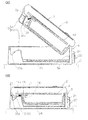
以下、本発明の実施形態を図面にしたがって説明する。図1は、本発明の第1実施形態に係る運転診断装置1を示す斜視図であり、図2(A)は、図1の運転診断装置を示す側方Sから見た分解構成図、(B)はその組立状態を示す構成図である。 Hereinafter, embodiments of the present invention will be described with reference to the drawings. FIG. 1 is a perspective view showing a driving diagnosis apparatus 1 according to the first embodiment of the present invention, and FIG. 2A is an exploded configuration view seen from a side S showing the driving diagnosis apparatus of FIG. B) is a configuration diagram showing the assembled state.
図1のように、本装置1は、持ち運び可能な装置本体2と、装置本体2を収納する凹部3aを有する設置ホルダ3とを備えている。設置ホルダ3は、車両内の任意場所、例えばダッシュボードDなどに配置され、装置本体2が設置ホルダ3の凹部3a内に着脱自在に装着される。設置ホルダ3の底面には、両面テープ24のような固定材(図2)が設けられている。運転診断装置1はほぼ直方体の形状であり、図1のようにダッシュボードDの平面部分に設置されているときには装置を寝かせた姿勢となり、垂直部分に設置されているときには装置を立たせた姿勢となる。
As shown in FIG. 1, the apparatus 1 includes a
図3に示すように、装置本体2は、例えば車両の加速度のような動作を検知して運転挙動を取得する加速度センサのような動作検知センサ5、制御部(マイクロコンピュータ)6、表示部7、および装置に電源を供給する電池8を有する。装置本体2は電池8で駆動し、常時電源オンの状態にある。また、ともに図示しない警報を報知する報知部、メモリおよび電源スイッチも設けられている。電源スイッチにより、装置本体2を長期間不使用の場合などに電源オフとされる。
As shown in FIG. 3, the apparatus
本装置1は、従来のように各種センサを併用することなく、動作検知センサとして加速度センサ5のみにより検知した車両の加速度から運転挙動を取得するものであり、制御部6は、取得された運転挙動に基づいてその判定を演算し当該運転の診断を行うものである。メモリは診断結果などを記憶する。運転挙動は少なくともブレーキ操作、アクセル操作およびハンドル操作を含む。
This apparatus 1 acquires driving behavior from the acceleration of the vehicle detected only by the
加速度センサ5は、車両の運転挙動を取得するために、前後、左右、上下の3軸の加速度のデータ(G表示)を得るもので、運転挙動のうち例えば急挙動の急アクセル、急ブレーキおよび急ハンドル(3急)の危険挙動や、スムーズな発進、停止のようなスムーズ運転挙動などを検知する。この加速度センサ5は、電池8から電源が常時供給されて、常時駆動状態にある。
The
なお、この例では、動作検知センサに加速度センサを使用して、車両の加速度によって運転挙動を取得しているが、これに代えて、例えばジャイロセンサを使用し車両の角速度によって運転挙動を取得することができるし、GPSセンサを使用し車両の時間ごとの速度変化による加速度によって運転挙動を取得することもできる。 In this example, an acceleration sensor is used as the motion detection sensor, and the driving behavior is acquired based on the acceleration of the vehicle. Instead, for example, a driving behavior is acquired based on the angular velocity of the vehicle using a gyro sensor. In addition, the driving behavior can be acquired by using the GPS sensor and the acceleration due to the speed change of the vehicle over time.
この運転診断装置1はリチウム電池のような電池8を搭載しているので、車両から電源を供給するための配線が不要であり、取り付け容易で車両内の任意の場所に設置することが可能となる。表示部7は、例えば液晶ディスプレイ(LCD)や発光ダイオード(LED)などからなり、診断結果などを表示する。
Since this driving diagnosis apparatus 1 is equipped with a
前記制御部6は、装置全体を制御するとともに、運転挙動判定部10を備えている。運転挙動判定部10は、運転挙動に基づいて、例えばスムーズ運転および危険運転の連続回数や平均回数により、安全運転および危険運転などを判定して当該運転を診断する。診断出力部11は、この診断結果を出力して、表示部7に表示させ、また危険運転に対して報知部からアラーム音(警報)を出させる。
The control unit 6 controls the entire apparatus and includes a driving
本装置1は、さらに、装置本体2が設置ホルダ3に装着されたことを検知するための装着検知機構13と、設置ホルダ3への装置本体2の装着検知後に、制御部6に加速度センサ5からの車両の加速度(動作)検知に基づき運転挙動の取り込みを開始させて、運転挙動の判定を行わせる運転挙動取込開始部12とを備えている。運転挙動取込開始部12は、装置本体2の装着を検知すると、装着検知信号を制御部6に出力し、制御部6は、この装着検知信号の入力に基づいて、運転挙動の取り込みを開始する。
The apparatus 1 further includes an
図2のように、装着検知機構13は例えばレバー(リーフ)スイッチのような検知スイッチであり、装置本体2側に設けられたスイッチ本体14と、設置ホルダ3側に設けられた突部のような被検知体16とを有している。この例では、振動による誤動作やアライメントが許容範囲内であることを前提として、接触型スイッチが使用されている。
As shown in FIG. 2, the
レバースイッチ13は、スイッチ本体14が装置本体2側の支持フレーム19に取り付けられており、装置本体2の装着時にスイッチ本体14のレバー14aと対向する位置で、設置ホルダ3側に上方へ突出する突部(被検知体)16が形成されている。装置本体2には、レバー14aの下方にガイド部2aが設けられて、装着時にこのガイド部2aに沿って突部16がガイドされる。
The
設置ホルダ3側に被検知体である突部16が形成されているので、設置ホルダ3に対する電源供給を不要として、その構成を簡単にしている。図4に示すように、この例では、2つのレバースイッチ13を有し、2個の突部16(図1)が設けられているが、これは後述するホルダ識別子17と兼用するためである。2つのレバースイッチ13のうちいずれか1つの検知で装置本体2の装着が検知される。なお、別途設けたホルダ識別子を使用する場合またはホルダ識別が不用の場合には、1個の突部16が設けられる。
Since the
図1のように、装置本体2の装着時に、設置ホルダ3に装置本体2をロックして固定するロック部20が設けられている。ロック部20は、周知構造のものが使用され、例えば設置ホルダ3側のほぼ正面中央に配置されたボタン21、および図示しない爪部とボタン21を付勢するばねとを有し、装置本体2側にはボタン受け部22およびロック時に爪部を係止する図示しない爪係止部を有する。ロック部20のボタンが押されると、爪部の係止が係脱されて、ロックが解除される。
As shown in FIG. 1, a
また、図2の装置本体2には、ロック部20(図では右側)と離間した位置(図では左側)に係合部2bが設けられており、設置ホルダ3の突部16に隣接して凹所からなる被係合部16aが設けられて、装置本体2の装着時に、係合部2bと被係合部16aが係合して、ロック部20とともに、設置ホルダ3に装置本体2が確実に固定される。これにより、設置ホルダ3から装置本体2のずれやこれに伴う装置本体2の振動が防止される。
2 is provided with an engaging
装置本体2が設置ホルダ3に装着されるとき、突部16がガイド部2bによりガイドされながら、レバースイッチ本体14のレバー14aを押し上げて、スイッチオンの状態になる。このとき、ロック部20によって装置本体2が設置ホルダ3にロックされて固定される。ボタン21が押されてロックが解除されると、装置本体2は設置ホルダ3から脱離するとともに、スイッチオフの状態になる。装置本体2が設置ホルダ3に装着されていないときには、スイッチオフ状態を保持する。
When the
この例では、検知スイッチとして接触型のレバースイッチを使用しているが、これに何ら限定されるものではなく、マグネットスイッチやリミットスイッチなどを使用してもよい。また、非接触型の光遮断を検知する検知センサ(フォトインタラプタ)などを使用してもよい。この場合も、検知センサの投受光器は装置本体2側に配置され、被検知体は設置ホルダ3側に配置される。
In this example, a contact lever switch is used as the detection switch, but the present invention is not limited to this, and a magnet switch, a limit switch, or the like may be used. Moreover, you may use the detection sensor (photointerrupter) etc. which detect non-contact-type light interruption. Also in this case, the light emitter / receiver of the detection sensor is arranged on the apparatus
図1の設置ホルダ3は複数の種類が設けられて、それぞれ相異なるホルダ識別子17を有し、装置本体2は、このホルダ識別子17を認識するホルダ識別子認識部15を有している。図4のように、この例では、装着検知で使用したレバースイッチ13を2個設けて、このホルダ識別に使用しており、レバースイッチ13は装着検知とホルダ識別を兼用している。
The
2個のレバースイッチ13および2個の突部16(17)により、3種類の設置ホルダ3を識別することができ、ホルダ識別子として2個の突部17の有無の組み合わせが予め設置ホルダ3ごとに決められている。例えば、図4(A)のように2個の突部17をH(有り)、H(有り)と配置させたものがNo.1、図4(B)のようにH(有り)、L(なし)の配置がNo.2、および図4(C)のようにL(なし)、H(有り)の配置がNo.3である。ホルダ識別子認識部15は2個のスイッチ本体14からの検知入力に基づいて、この検知の組み合わせにより、設置ホルダ3を識別する。例えば、スイッチ本体14が突部17のH(有り)、H(有り)を同時に検知したとき、図4(A)のNo.1の設置ホルダ3と識別される。
Three types of
この例では、レバースイッチ13が装着検知とホルダ識別を兼用しているので、簡単な構成で装置本体2の設置ホルダ3への装着検知および複数の設置ホルダのホルダ識別が容易にできる。
In this example, since the
なお、ホルダ識別子として突部17を3個以上設けてもよく、その有無の組み合わせの数を多くすることにより、多種類の設置ホルダ3を識別することができる。
Note that three or
こうして、車両に取り付ける設置ホルダ3を識別することにより、車両の種類を認識することができる。車両の種類によって、設置ホルダ3の取り付け場所が異なり、その設置角度も異なる場合があるため、車両の種類ごとに装置本体2内の加速度センサ5からの加速度データを補正して、運転挙動を補正する必要があるが、予めホルダ3を識別して、装置の設置角度がわかっているとき、加速度データの補正が容易となる。これにより、設置ホルダ3の種類を各別に認識できるので、車両の種類に応じた運転挙動の補正を容易にできる。
Thus, the type of vehicle can be recognized by identifying the
図5は、第2実施形態に係る運転診断装置1を示すブロック構成図である。第1実施形態では、接触型のレバースイッチを使用し、ホルダ識別を装着検知と兼用にして、その組み合わせで行っているが、第2実施形態では、両者を兼用とせず、ホルダ識別を装置検知と別途設けている。その他の構成は、第1実施形態と同様である。 FIG. 5 is a block configuration diagram showing the driving diagnosis apparatus 1 according to the second embodiment. In the first embodiment, a contact-type lever switch is used, and holder identification is combined with mounting detection, and the combination is performed. However, in the second embodiment, both are not combined and holder identification is performed by device detection. Are provided separately. Other configurations are the same as those of the first embodiment.
例えば、ホルダ識別子として、上記したような接触型のほかに、バーコードやICカードなどの非接触型も使用される。この場合においても、装置本体2側に読取装置が配置され、設置ホルダ3側にバーコードやICカードなどが配置される。
For example, in addition to the contact type as described above, a non-contact type such as a barcode or an IC card is also used as the holder identifier. Also in this case, a reading device is disposed on the apparatus
以上のように、本発明では、電池で駆動して持ち運び可能であり、運転挙動を取得する動作検知センサが常時駆動状態にあるので、装置の利便性および取扱性を高くできる。これとともに、装置本体が車両内の任意場所に設置されたことが検知されるので、装置本体が車両内に設置された状態と、持ち運ばれている途中で設置されていない状態との区別が容易となる。また、運転挙動取込開始部により装置本体の設置検知後に、運転挙動の取り込みが開始されて運転挙動が判定されるので、制御部における演算を可及的に少なくして、電池の消耗を少なくできる。これにより、電池で駆動し持ち運び可能な装置で、装置本体の設置状態の区別により運転診断の信頼性を向上させるとともに省電力を図り、装置の利便性および取扱性をより向上させることができる。 As described above, in the present invention, the battery can be driven and carried by a battery, and the motion detection sensor for acquiring the driving behavior is always in the driving state, so that the convenience and handling of the device can be improved. At the same time, since it is detected that the device main body is installed in an arbitrary place in the vehicle, there is a distinction between the state in which the device main body is installed in the vehicle and the state in which the device main body is not installed in the middle of being carried. It becomes easy. In addition, since the driving behavior capture is started and the driving behavior is determined after the driving behavior capturing start unit detects the installation of the apparatus main body, the calculation in the control unit is reduced as much as possible to reduce battery consumption. it can. Thereby, it is a battery-powered apparatus that can be carried and can improve the reliability of operation diagnosis by distinguishing the installation state of the apparatus main body, and can save power, thereby further improving the convenience and handling of the apparatus.
各実施形態では、装着本体2が装着される設置ホルダ3が設けられているが、この設置ホルダ3を省略してもよい。この場合、装置本体2は直接、両面テープやマジックテープ(登録商標)のような固定材により車両内のダッシュボードDのような任意場所に貼り付けられて設置される。装置本体2が直接設置されたことの検知は、例えば、装置本体2の設置角度が既知であれば、その設置状態を加速度センサにより検知して行うことができる。
In each embodiment, the
その他、装置本体2の直接設置の検知方法としては、エンジンスタート時におけるキーの認証電波や、車両情報(車速、回転数、燃料使用量など)などの電波を使用して車両を識別して、装置本体2の設置検知を行うことができる。また、各車両内に特有の光や音などが存在する場合には、これらを検知することによって車両を識別することもできる。
In addition, as a detection method of the direct installation of the apparatus
なお、各実施形態では、設置ホルダ3の種類を各別に識別しているが、必要に応じてホルダ識別を省略してもよい。
In addition, in each embodiment, although the kind of
また、運転診断装置1に通信機能をもたせて、運転挙動の診断出力や識別した設置ホルダ3の種類などを通信できるようにしてもよい。
Further, the driving diagnosis apparatus 1 may be provided with a communication function so that the driving behavior diagnosis output, the type of the identified
1:運転診断装置
2:装置本体
3:設置ホルダ
5:動作検知センサ(加速度センサ)
6:制御部
8:電池
10:運転挙動判定部
12:運転挙動取込開始部
13:装着検知機構(検知スイッチ)
14:スイッチ本体
15:識別子認識部
16:被検知体
17:ホルダ識別子
1: Driving diagnosis device 2: Device body 3: Installation holder 5: Motion detection sensor (acceleration sensor)
6: Control unit 8: Battery 10: Driving behavior determination unit 12: Driving behavior capture start unit 13: Mounting detection mechanism (detection switch)
14: Switch body 15: Identifier recognition unit 16: Object to be detected 17: Holder identifier
Claims (6)
前記動作検知センサは常時駆動状態にあり、
前記装置本体が車両内の任意場所に設置されたことの検知後に、前記制御部に前記動作検知センサからの車両動作の検知に基づき運転挙動の取り込みを開始させて、運転挙動の判定を行わせる運転挙動取込開始部が設けられている、運転診断装置。 A portable device main body having a control unit that is driven by a battery and obtains a driving behavior from a motion of a vehicle detected by a motion detection sensor, determines the driving behavior, and diagnoses the driving. A driving diagnosis device whose main body is installed in an arbitrary place in the vehicle,
The motion detection sensor is always driven,
After detecting that the apparatus main body is installed in an arbitrary place in the vehicle, the control unit is caused to start taking in driving behavior based on detection of vehicle motion from the motion detection sensor and to determine driving behavior. A driving diagnosis device provided with a driving behavior capturing start unit.
車両内の任意場所に設置されて、前記装置本体が着脱自在に装着される設置ホルダと、前記装置本体が前記設置ホルダに装着されたことを検知するための設置検知機構とを備え、
前記運転挙動取込開始部は、前記設置ホルダへの前記装置本体の設置検知後に、運転挙動の取り込みを開始させて、運転挙動の判定を行う、運転診断装置。 In claim 1,
An installation holder installed in an arbitrary place in the vehicle, wherein the apparatus main body is detachably mounted; and an installation detection mechanism for detecting that the apparatus main body is mounted on the installation holder,
The driving behavior taking-in start unit is a driving diagnosis device that starts taking in driving behavior and determines driving behavior after detecting the installation of the apparatus main body to the installation holder.
前記装着検知機構は検知スイッチからなり、前記装置本体側にスイッチ本体を、前記設置ホルダ側に被検知体を有している、運転診断装置。 In claim 2,
The mounting diagnosis mechanism includes a detection switch, and includes a switch body on the apparatus body side and a detected body on the installation holder side.
前記設置ホルダは複数の種類が設けられて、それぞれ相異なるホルダ識別子を有し、前記装置本体は、このホルダ識別子を認識するホルダ識別子認識部を有している、運転診断装置。 In claim 2,
A plurality of types of installation holders are provided, each having a different holder identifier, and the apparatus main body has a holder identifier recognition unit that recognizes the holder identifier.
複数の前記被検知体が前記ホルダ識別子を構成している、運転診断装置。 In claim 3,
A driving diagnosis device in which a plurality of detected objects constitute the holder identifier.
前記動作検知センサは、加速度センサ、ジャイロセンサまたはGPSセンサである、運転診断装置。 In claim 1,
The operation diagnosis sensor is a driving diagnosis device, which is an acceleration sensor, a gyro sensor, or a GPS sensor.
Priority Applications (1)
| Application Number | Priority Date | Filing Date | Title |
|---|---|---|---|
| JP2014076831A JP2015197876A (en) | 2014-04-03 | 2014-04-03 | driving diagnostic device |
Applications Claiming Priority (1)
| Application Number | Priority Date | Filing Date | Title |
|---|---|---|---|
| JP2014076831A JP2015197876A (en) | 2014-04-03 | 2014-04-03 | driving diagnostic device |
Publications (1)
| Publication Number | Publication Date |
|---|---|
| JP2015197876A true JP2015197876A (en) | 2015-11-09 |
Family
ID=54547496
Family Applications (1)
| Application Number | Title | Priority Date | Filing Date |
|---|---|---|---|
| JP2014076831A Pending JP2015197876A (en) | 2014-04-03 | 2014-04-03 | driving diagnostic device |
Country Status (1)
| Country | Link |
|---|---|
| JP (1) | JP2015197876A (en) |
Cited By (1)
| Publication number | Priority date | Publication date | Assignee | Title |
|---|---|---|---|---|
| KR20190070450A (en) * | 2017-12-13 | 2019-06-21 | (주)자스텍엠 | Apparatus for processing vehicle information |
Citations (5)
| Publication number | Priority date | Publication date | Assignee | Title |
|---|---|---|---|---|
| JP2003207350A (en) * | 2002-01-09 | 2003-07-25 | Navitime Japan Co Ltd | Map display device in on-vehicle as well as portable mode |
| JP2005316954A (en) * | 2004-03-31 | 2005-11-10 | Denso Corp | On-vehicle device |
| JP2008014660A (en) * | 2006-07-03 | 2008-01-24 | Pioneer Electronic Corp | Navigation device and method, navigation program and memory medium |
| JP2011171798A (en) * | 2010-02-16 | 2011-09-01 | Kddi Corp | Mobile phone functioning as drive recorder, program and drive recording method |
| JP2012185537A (en) * | 2011-03-03 | 2012-09-27 | Data Tec:Kk | Operation management device mounted on mobile body, portable information terminal, operation management server, and computer program |
-
2014
- 2014-04-03 JP JP2014076831A patent/JP2015197876A/en active Pending
Patent Citations (5)
| Publication number | Priority date | Publication date | Assignee | Title |
|---|---|---|---|---|
| JP2003207350A (en) * | 2002-01-09 | 2003-07-25 | Navitime Japan Co Ltd | Map display device in on-vehicle as well as portable mode |
| JP2005316954A (en) * | 2004-03-31 | 2005-11-10 | Denso Corp | On-vehicle device |
| JP2008014660A (en) * | 2006-07-03 | 2008-01-24 | Pioneer Electronic Corp | Navigation device and method, navigation program and memory medium |
| JP2011171798A (en) * | 2010-02-16 | 2011-09-01 | Kddi Corp | Mobile phone functioning as drive recorder, program and drive recording method |
| JP2012185537A (en) * | 2011-03-03 | 2012-09-27 | Data Tec:Kk | Operation management device mounted on mobile body, portable information terminal, operation management server, and computer program |
Cited By (2)
| Publication number | Priority date | Publication date | Assignee | Title |
|---|---|---|---|---|
| KR20190070450A (en) * | 2017-12-13 | 2019-06-21 | (주)자스텍엠 | Apparatus for processing vehicle information |
| KR102074905B1 (en) * | 2017-12-13 | 2020-02-07 | (주)자스텍엠 | Apparatus for processing vehicle information |
Similar Documents
| Publication | Publication Date | Title |
|---|---|---|
| US9168862B2 (en) | Helmet apparatus for automated vehicle heading alert | |
| CN102107630B (en) | Operation apparatus for on-board devices in automobile | |
| CN109599101A (en) | The external voice monitoring based on accelerometer independently stopped for voice control | |
| JP2010052635A (en) | Device for preventing drunken driving | |
| JP2011225189A (en) | Vehicle failure warning device and vehicle failure warning system | |
| CN112689587A (en) | Method for classifying non-driving task activities in consideration of interruptability of non-driving task activities of driver when taking over driving task is required and method for releasing non-driving task activities again after non-driving task activities are interrupted due to taking over driving task is required | |
| JP2013023868A (en) | Function integrated receiver | |
| KR101202918B1 (en) | Charger of electric vehicles and control method thereof | |
| JP2015197876A (en) | driving diagnostic device | |
| CN106945602A (en) | There is the system for prompting of baby in vehicle | |
| JP2015017404A (en) | Vehicle key | |
| JP4840243B2 (en) | Automotive portable navigator | |
| JP2014241038A (en) | Drive recorder | |
| US20170024940A1 (en) | Drive diagnosing device | |
| EP3121794A1 (en) | Drive diagnosing device | |
| JP5700792B2 (en) | Operation recording apparatus and data reading method thereof | |
| JP6062725B2 (en) | Holding system, communication system, and holding method | |
| JP2022134915A (en) | Detection function control device, detection function control method, and program | |
| JP2017207795A (en) | Gesture operated device | |
| KR101096125B1 (en) | Multi functional information device using by vehicle | |
| JP2016057987A (en) | Small-sized electronic apparatus | |
| JP6045301B2 (en) | Holding device and holding method | |
| JP7144268B2 (en) | taximeter | |
| KR20140032844A (en) | The vehicle monitoring system and the monitoring method of the vehicle | |
| JP2009048561A (en) | Onboard device with lighting |
Legal Events
| Date | Code | Title | Description |
|---|---|---|---|
| A621 | Written request for application examination |
Free format text: JAPANESE INTERMEDIATE CODE: A621 Effective date: 20170315 |
|
| A711 | Notification of change in applicant |
Free format text: JAPANESE INTERMEDIATE CODE: A712 Effective date: 20170407 |
|
| RD03 | Notification of appointment of power of attorney |
Free format text: JAPANESE INTERMEDIATE CODE: A7423 Effective date: 20170407 |
|
| A521 | Request for written amendment filed |
Free format text: JAPANESE INTERMEDIATE CODE: A523 Effective date: 20170517 |
|
| A625 | Written request for application examination (by other person) |
Free format text: JAPANESE INTERMEDIATE CODE: A625 Effective date: 20170315 |
|
| A977 | Report on retrieval |
Free format text: JAPANESE INTERMEDIATE CODE: A971007 Effective date: 20171213 |
|
| A131 | Notification of reasons for refusal |
Free format text: JAPANESE INTERMEDIATE CODE: A131 Effective date: 20171219 |
|
| A02 | Decision of refusal |
Free format text: JAPANESE INTERMEDIATE CODE: A02 Effective date: 20180703 |