JP2015194591A - adhesive tape roll - Google Patents
adhesive tape roll Download PDFInfo
- Publication number
- JP2015194591A JP2015194591A JP2014072197A JP2014072197A JP2015194591A JP 2015194591 A JP2015194591 A JP 2015194591A JP 2014072197 A JP2014072197 A JP 2014072197A JP 2014072197 A JP2014072197 A JP 2014072197A JP 2015194591 A JP2015194591 A JP 2015194591A
- Authority
- JP
- Japan
- Prior art keywords
- layer
- adhesive tape
- printed
- release agent
- tape
- Prior art date
- Legal status (The legal status is an assumption and is not a legal conclusion. Google has not performed a legal analysis and makes no representation as to the accuracy of the status listed.)
- Pending
Links
Images


Abstract
Description
本発明は、被着体に貼り付けて使用可能な印字済み粘着テープを用いた、(印字済みの)粘着テープロールに関する。 The present invention relates to a (printed) adhesive tape roll using a printed adhesive tape that can be used by being attached to an adherend.
印刷対象に対しインクにより印刷を行う印刷装置が知られている(例えば、特許文献1参照)。この従来技術では、トレイに順次投入される紙様状の記録媒体に対し、インク用印字ヘッドからインクが吐出された後、さらにオーバーコート用のヘッドから後処理液が吐出されることで、インク層の保護(オーバーコーティング)が行われる。 2. Description of the Related Art A printing apparatus that performs printing with ink on a printing target is known (for example, see Patent Document 1). In this prior art, after the ink is ejected from the ink print head and then the post-treatment liquid is ejected from the overcoat head to the paper-like recording medium sequentially put into the tray, the ink Layer protection (overcoating) is performed.
一方、粘着テープに対して印字を行う印刷装置が提唱されつつある。この印刷装置では、例えば、被印字粘着テープロールから繰り出されて搬送される被印字粘着テープに対しヘッドからインクが吐出され、当該被印字粘着テープのテープ基材層の上にインク層が形成されて、印字済み粘着テープが生成される。生成された上記印字済み粘着テープは再びロール状に巻き取られ、(印字済みの)粘着テープロールとなる。ユーザは、この粘着テープロールから所望の長さの印字済み粘着テープを繰り出し、上記テープ基材層の裏面に設けられた粘着層によって適宜の被着体に対し貼り付けることで、使用することができる。 On the other hand, printing apparatuses that perform printing on adhesive tapes are being proposed. In this printing apparatus, for example, ink is ejected from the head onto the print-receiving adhesive tape that is fed out and conveyed from the print-receiving adhesive tape roll, and an ink layer is formed on the tape base layer of the print-receiving adhesive tape. Thus, a printed adhesive tape is generated. The generated printed adhesive tape is again wound up into a roll to form an (printed) adhesive tape roll. The user can use the adhesive tape roll by printing out the adhesive tape with a desired length from the adhesive tape roll and sticking it to an appropriate adherend with the adhesive layer provided on the back surface of the tape base layer. it can.
上記のようにユーザが粘着テープを貼り付けて使用するときに、表面に汚れやゴミが付着する場合があり、これを防止するために、テープ基材層の表面に剥離層を設けることが考えられる。この場合、上記印字済み粘着テープは、上述したインク層、剥離層、テープ基材層、及び粘着層、をこの順序で含むことから、上記(印字済みの)粘着テープロールにおいては、インク層と粘着層とがロールの径方向に接する状態となる。この結果、上記のようにユーザが粘着テープロールから印字済み粘着テープを繰り出して使用するときにインク層が粘着層側へと引き剥がされ、印字内容に悪影響を与えるおそれがある。 As described above, when a user sticks an adhesive tape and uses it, dirt or dust may adhere to the surface, and in order to prevent this, it is considered to provide a release layer on the surface of the tape base layer. It is done. In this case, since the printed adhesive tape includes the above-described ink layer, release layer, tape base layer, and adhesive layer in this order, in the (printed) adhesive tape roll, The pressure-sensitive adhesive layer comes into contact with the roll in the radial direction. As a result, as described above, when the user pulls out the printed adhesive tape from the adhesive tape roll and uses it, the ink layer is peeled off to the adhesive layer side, which may adversely affect the printed content.
また、被印字粘着テープが上記積層構造を有することにより、上記被印字粘着テープロールにおいては、剥離層が、上記粘着層と接して粘着した状態となっている。前述のように粘着テープロールから被印字粘着テープが繰り出されるときには、上記粘着層が剥離層から順次引き剥がされて剥離されることとなるので、その剥離性を向上させるための配慮も必要となる。 In addition, since the print-receiving pressure-sensitive adhesive tape has the above-described laminated structure, in the print-ready pressure-sensitive adhesive tape roll, the release layer is in contact with and sticking to the pressure-sensitive adhesive layer. As described above, when the printing adhesive tape is fed out from the adhesive tape roll, the adhesive layer is peeled off and peeled from the release layer in order, so that consideration for improving the peelability is also necessary. .
上記のような種々の制約のために、剥離層を構成する剥離剤の選定が難しく、結果として、上述した印字済み粘着テープロールからの繰り出し時における印字内容への悪影響防止、被印字粘着テープロールからの繰り出し時における剥離性向上、及び使用時の防汚性確保のすべてを満足するのは難しかった。 Due to various restrictions as described above, it is difficult to select a release agent that constitutes the release layer, and as a result, it is possible to prevent adverse effects on the printing contents when the above-mentioned printed adhesive tape roll is fed out, and to be printed adhesive tape roll. It was difficult to satisfy all of the improvement in peelability during unwinding and the securing of antifouling properties during use.
上記従来技術においては、上述したような、印字内容への悪影響を防止し、また剥離性を向上し、防汚性を維持できる、最適な特性を実現することまでは配慮されていなかった。 In the prior art described above, no consideration has been given to the realization of optimum characteristics that can prevent the adverse effects on the print contents as described above, improve the peelability, and maintain the antifouling property.
本発明の目的は、印字済み粘着テープロールからの繰り出し時における印字内容への悪影響を防止し、また被印字粘着テープロールからの繰り出し時における剥離性を向上し、さらに貼り付けて使用されるときの防汚性を維持できる、粘着テープロールを提供することにある。 The purpose of the present invention is to prevent adverse effects on the printed contents when fed out from the printed adhesive tape roll, improve the peelability when fed out from the printed adhesive tape roll, and when used after being attached. It is providing the adhesive tape roll which can maintain antifouling property.
上記目的を達成するために、本願発明は、厚さ方向寸法を備え、テープ本体と、インクジェットヘッドからの吐出により前記テープ本体に形成された印字層と、を有する印字済み粘着テープであって、前記テープ本体が、テープ基材層と、前記テープ基材層の前記厚さ方向の一方側に設けられ所定の粘着剤により構成された粘着層と、前記テープ基材層の前記厚さ方向の他方側に設けられた剥離層と、を有し、前記剥離層が、オレフィン樹脂系剥離剤、若しくは、長鎖アルキル基を有するアクリル樹脂系剥離剤であって、かつ、重合度が互いに異なる複数種類の重合成分を混合した剥離剤によって構成されており、前記印字層が、前記剥離層の前記他方側に形成されている、前記印字済み粘着テープを、前記剥離層を外周側としつつ所定の軸芯回りに巻回して構成されたことを特徴とする。 In order to achieve the above object, the present invention is a pressure-sensitive adhesive tape that has a dimension in the thickness direction and has a tape body and a print layer formed on the tape body by ejection from an inkjet head, The tape body includes a tape base layer, an adhesive layer provided on one side of the tape base layer in the thickness direction and configured by a predetermined adhesive, and the tape base layer in the thickness direction. A release layer provided on the other side, wherein the release layer is an olefin resin release agent or an acrylic resin release agent having a long-chain alkyl group, and having a different degree of polymerization The print layer is formed on the other side of the release layer, and the printed adhesive tape is formed on the outer peripheral side of the print layer. axis Characterized in that it is formed by winding around.
本願発明の粘着テープロールに巻回される印字済み粘着テープは、テープ本体に対して、インクジェットヘッドからの吐出により印字層が形成されることにより、構成されている。すなわち、本願発明においては、例えば被印字粘着テープロールから繰り出された、所定の積層構造のテープ本体(被印字粘着テープ)に印字層が形成されて上記印字済み粘着テープとなり、その印字済み粘着テープが巻回されて上記(印字済みの)粘着テープロールが生成される。その後、ユーザは、所望の長さのこの印字済み粘着テープを上記(印字済みの)粘着テープロールから繰り出して適宜の被着体に対し貼り付けることで、例えばラベルや梱包用の封止材として使用する。このとき、上記テープ本体は、例えば、厚さ方向の他方側(例えば上側)から一方側(例えば下側)に向かって、剥離層、テープ基材層、及び粘着層、をこの順序で含む。テープ基材層の上記他方側に剥離層が設けられていることにより、上記のようにラベルや封止材として使用されるときに表面に汚れやゴミが付着しにくくなり、防汚性を保つことができる。 The printed adhesive tape wound around the adhesive tape roll of the present invention is configured by forming a printing layer on the tape body by discharging from an inkjet head. That is, in the present invention, for example, a printed layer is formed on a tape body (printed adhesive tape) having a predetermined laminated structure that is fed from a printed adhesive tape roll to form the printed adhesive tape. Is wound to produce the above-mentioned (printed) adhesive tape roll. Thereafter, the user feeds out the printed adhesive tape having a desired length from the (printed) adhesive tape roll and affixes it to an appropriate adherend, for example, as a label or a sealing material for packing. use. At this time, the said tape main body contains a peeling layer, a tape base material layer, and an adhesion layer in this order from the other side (for example, upper side) of thickness direction toward one side (for example, lower side), for example. By providing a release layer on the other side of the tape base layer, when used as a label or sealing material as described above, it becomes difficult for dirt and dust to adhere to the surface, thus maintaining antifouling properties. be able to.
また、本願発明においては、上記印字済み粘着テープが、所定の軸芯まわりに巻回したロールとして生成される。上述のように印字済み粘着テープのテープ本体が剥離層、テープ基材層、及び粘着層、をこの順序で含むことから、本願発明の上記(印字済みの)粘着テープロールにおいては、印字層が形成されている部分では、印字層の他方側(例えば上側)表面と粘着層とがロールの径方向に接する状態となる。このとき、印字層と剥離層との密着性が小さいと、ロールから印字済み粘着テープが繰り出されて使用されるとき、剥離層に形成された上記印字層が再び粘着層側へと引き剥がされ、印字に悪影響を与える恐れがある。 In the present invention, the printed adhesive tape is produced as a roll wound around a predetermined axis. As described above, since the tape body of the printed adhesive tape includes the release layer, the tape base layer, and the adhesive layer in this order, in the above-mentioned (printed) adhesive tape roll of the present invention, the printed layer is In the formed part, the other side (for example, upper side) surface of the printing layer and the adhesive layer are in contact with each other in the radial direction of the roll. At this time, if the adhesiveness between the print layer and the release layer is small, when the printed adhesive tape is unwound from the roll and used, the print layer formed on the release layer is peeled off again to the adhesive layer side. There is a risk of adversely affecting printing.
そこで本願発明においては、剥離層を、オレフィン樹脂系剥離剤、若しくは、長鎖アルキル基を有するアクリル樹脂系剥離剤で、かつ、重合度が互いに異なる複数種類の重合成分を混合した剥離剤によって構成する。このような剥離剤によって構成された剥離層では、印字層を構成するインク粒子が入り込むことのできる微視的な隙間が、剥離層を構成する分子どうしの間に多数形成される。したがって、上記のようにしてインクジェットヘッドから吐出されたインクにより形成される印字層を、テープ本体の剥離層に対し強固に密着させることができる。これにより、上記のような印字層の引き剥がしを防止することができる。この結果、上記ユーザの使用時における(印字済みの)粘着テープロールからの繰り出しの際に、印字層が、ロール中で隣接する粘着層側へと引き剥がされるのを防止することができる。 Therefore, in the present invention, the release layer is composed of an olefin resin release agent or an acrylic resin release agent having a long chain alkyl group, and a release agent in which a plurality of types of polymerization components having different degrees of polymerization are mixed. To do. In the release layer constituted by such a release agent, a large number of microscopic gaps in which the ink particles constituting the print layer can enter are formed between the molecules constituting the release layer. Therefore, the printing layer formed by the ink ejected from the inkjet head as described above can be firmly adhered to the release layer of the tape body. Thereby, peeling of the print layer as described above can be prevented. As a result, it is possible to prevent the print layer from being peeled off to the adjacent adhesive layer side in the roll when the user uses the adhesive tape roll (printed) at the time of use.
さらに、上述のように、上記テープ本体は、厚さ方向の他方側(例えば上側)から一方側(例えば下側)に向かって、剥離層、テープ基材層、及び粘着層、をこの順序で含む積層構造となっている。したがって、上記被印字粘着テープロールにおいては、上記粘着層は、ロールの径方向に剥離層と接して粘着した状態となる。上記剥離層はこの粘着層との粘着を再剥離しやすくすることも目的として設けられており、前述のようにして被印字粘着テープロールから被印字粘着テープが繰り出されるときには、上記粘着層が、適宜の剥離剤からなる剥離層から順次引き剥がされて剥離される。これにより、上記被印字粘着テープロールからの被印字粘着テープが繰り出される時における剥離層からの剥離性を向上することができる。 Furthermore, as described above, the tape main body has the release layer, the tape base layer, and the adhesive layer in this order from the other side (for example, the upper side) in the thickness direction toward the one side (for example, the lower side). It is a laminated structure including. Therefore, in the above-mentioned pressure-sensitive adhesive tape roll to be printed, the above-mentioned adhesive layer is in a state of being in contact with the release layer in the radial direction of the roll. The release layer is also provided for the purpose of facilitating the re-peeling of the adhesive with the adhesive layer, and when the printable adhesive tape is fed out from the printable adhesive tape roll as described above, the adhesive layer is The release layer made of an appropriate release agent is sequentially peeled off. Thereby, the peelability from the peeling layer when the printing adhesive tape from the printing adhesive tape roll is fed out can be improved.
以上のように、本願発明においては、被印字粘着テープロールからの繰り出し時における被印字粘着テープの剥離性を向上しつつ、(印字済みの)粘着テープロールからの繰り出し時における印字内容への悪影響を防止し、さらに印字済みの粘着テープが貼り付けて使用されるときの防汚性を維持できる、最適な特性の印字済み粘着テープを実現することができる。 As described above, in the present invention, while improving the peelability of the printed adhesive tape at the time of feeding from the printed adhesive tape roll, the adverse effect on the printed contents at the time of feeding from the (printed) adhesive tape roll. In addition, it is possible to realize a printed adhesive tape having optimum characteristics that can prevent contamination and maintain antifouling properties when a printed adhesive tape is attached and used.
本発明によれば、印字済み粘着テープロールからの繰り出し時における印字内容への悪影響を防止し、また被印字粘着テープロールからの繰り出し時における剥離性を向上し、さらに貼り付けて使用されるときの防汚性を維持することができる。 According to the present invention, when printing from the printed adhesive tape roll is prevented, the printed content is prevented from being adversely affected. In addition, when the tape is fed from the print-targeted adhesive tape roll, the peelability is improved. Antifouling property can be maintained.
以下、本発明の一実施の形態について図面を参照しつつ説明する。なお、図面中に「前方」「後方」「左方」「右方」「上方」「下方」の注記がある場合は、明細書中の説明における「前方(前)」「後方(後)」「左方(左)」「右方(右)」「上方(上)」「下方(下)」とは、その注記された方向を指す。 Hereinafter, an embodiment of the present invention will be described with reference to the drawings. In addition, when there are notes “front”, “rear”, “left”, “right”, “upper”, “lower” in the drawings, “front (front)” “rear (rear)” in the description in the specification “Left (left)”, “right (right)”, “upper (upper)” and “lower (lower)” refer to the noted direction.
<粘着テープ印刷装置の概略構成>
まず、図1〜図3を参照しつつ、本実施形態における粘着テープ印刷装置の概略構成について説明する。
<Schematic configuration of adhesive tape printer>
First, a schematic configuration of the pressure-sensitive adhesive tape printer according to the present embodiment will be described with reference to FIGS.
<筐体>
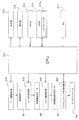
図1及び図2において、本実施形態の粘着テープ印刷装置1は、装置外郭を構成する筐体2を有している。筐体2は、筐体本体2aと、後方側開閉部8と、前方側開閉カバー9と、を備えている。
<Case>
1 and 2, an
筐体本体2a内には、後方側に設けられた第1収納部3と、前方側に設けられた第2収納部5及び第3収納部4と、が備えられている。
The housing
後方側開閉部8は、筐体本体2aの後方側の上部に対し開閉可能に接続されている。この後方側開閉部8は、回動することで、第1収納部3の上方を開閉可能である。この後方側開閉部8は、第1開閉カバー8a及び第2開閉カバー8bにより構成されている。
The rear side opening /
第1開閉カバー8aは、筐体本体2aの後方側の上部に設けられた所定の回動軸心K1まわりに回動することで、第1収納部3のうち前方側の上方を開閉可能である。詳細には、第1開閉カバー8aは、第1収納部3のうち前方側の上方を覆う閉じ位置(図1、図2の状態)から、第1収納部3のうち前方側の上方を露出させる開き位置までの間で回動可能である。
The first opening /
第1開閉カバー8aの内部には、インクジェットヘッド10aを備えたヘッド保持体10が設けられている。そして、第1開閉カバー8aは、上記の回動軸心K1まわりに回動することで、ヘッド保持部10に備えられた上記インクジェットヘッド10aを、筐体本体2aに設けられた搬送ローラ12によるテープ搬送経路に対して相対的に離反・近接可能である。詳細には、第1開閉カバー8aは、インクジェットヘッド10aがテープ搬送経路に対して近接した閉じ位置(図2の状態)から、インクジェットヘッド10aがテープ搬送経路から離反した開き位置までの間で回動可能である。
Inside the first opening /
第2開閉カバー8bは、上記第1開閉カバー8aよりも後方側に設けられており、筐体本体2aの後方側の上端部に設けられた所定の回動軸心K2まわりに回動することで、第1収納部3のうち後方側の上方を、上記第1開閉カバー8aの開閉とは別個に開閉可能である。詳細には、第2開閉カバー8bは、第1収納部3のうち後方側の上方を覆う閉じ位置(図2の状態)から、第1収納部3のうち後方側の上方を露出させる開き位置までの間で回動可能である。
The second opening /
そして、これら第1開閉カバー8a及び第2開閉カバー8bは、それぞれが閉じ状態であるときに、当該第1開閉カバー8aの外周部18と当該第2開閉カバー8bの縁部19とが互いに略接触して、第1収納部3の上方の略全部を覆うように構成されている。
When the first opening /
前方側開閉カバー9は、筐体本体2aの前方側の上部に対し開閉可能に接続されている。この前方側開閉カバー9は、筐体本体2aの前方側の上端部に設けられた所定の回動軸心K3まわりに回動することで、第3収納部4の上方を開閉可能である。詳細には、前方側開閉カバー9は、第3収納部4の上方を覆う閉じ位置(図2の状態)から、第3収納部4の上方を露出させる開き位置までの間で回動可能である。
The front side opening /
<被印字テープロール及びその周辺>
このとき、図2及び図3に示すように、筐体本体2aにおける、閉じ状態での前方側開閉カバー9の下方にある第1所定位置13には、テープカートリッジTKが着脱可能に装着される。このテープカートリッジTKは、軸芯O1まわりに巻回形成された被印字テープロールR1を備えている。
<Printed tape roll and its surroundings>
At this time, as shown in FIGS. 2 and 3, the tape cartridge TK is detachably attached to the first
すなわち、テープカートリッジTKは、図3に示すように、被印字テープロールR1と、連結アーム16とを備えている。連結アーム16は、後方側に設けられた左・右一対の第1ブラケット部20,20と、前方側に設けられた左・右一対の第2ブラケット部21,21とを備えている。
That is, the tape cartridge TK includes a print-receiving tape roll R1 and a connecting
第1ブラケット部20,20は、上記被印字テープロールR1を、軸芯O1に沿った左・右両側から挟みこむようにし、テープカートリッジTKが筐体本体2aに装着された状態では被印字テープロールR1を巻芯39(図2参照)のまわりに回転可能に保持する。これら第1ブラケット部20,20は、上端部において左右方向に略沿って延設された第1接続部22により被印字テープロールR1の外径との干渉を回避しつつ接続されている。
The
被印字テープロールR1は、テープカートリッジTKが筐体本体2aの内部に装着された際には回転自在となる。被印字テープロールR1は、繰り出しにより消費される被印字粘着テープ150(後述する剥離剤層154、基材層153、粘着剤層152、剥離材151を備える。図2中拡大図参照)を、あらかじめ左右方向の軸芯O1まわりに巻回している。
The print-receiving tape roll R1 is rotatable when the tape cartridge TK is mounted inside the
第1収納部3には、上記テープカートリッジTKの装着によって、被印字テープロールR1が上方から受け入れられ、被印字粘着テープ150の巻回の軸芯O1が左右方向となる状態で収納される。そして、被印字テープロールR1は、第1収納部3に収納された状態(テープカートリッジTKが装着された状態)において当該第1収納部3内で所定の回転方向(図2中のA方向)に回転することで、被印字粘着テープ150を繰り出す。
By mounting the tape cartridge TK, the print-receiving tape roll R1 is received from above and is stored in the first storage unit 3 in a state where the winding axis O1 of the print-receiving
本実施形態では、粘着性を備えた被印字粘着テープ150が用いられる場合を例示している。すなわち、被印字粘着テープ150は、剥離材151、粘着剤層152(粘着層に相当)、基材層153(テープ基材層に相当)、及び剥離剤層154(剥離層に相当)が、厚さ方向一方側(図2の拡大図中の下方側)から他方側(図2の拡大図中の下方側)へ向かって、この順序で積層されている。剥離剤層154は、上記インクジェットヘッド10aによるインク(染料系又は顔料系のいずれでもよい)の吐出によって所望の印字を形成する印字層155(図2中の部分拡大図参照。詳細は後述)が形成される層である。粘着剤層152は、基材層153を適宜の被着体(図示省略)に貼り付けるための層である。剥離材151は、粘着剤層152を覆う層である。なお、剥離材151、粘着剤層152、基材層153、及び剥離剤層154が、各請求項記載のテープ本体に相当している。
In this embodiment, the case where the to-be-printed
<剥離層の具体例>
上記剥離剤層154を形成する剥離剤としては、オレフィン樹脂系剥離剤、若しくは、長鎖アルキル基を有するアクリル樹脂系剥離剤等を使用することができる。
<Specific examples of release layer>
As the release agent for forming the
<オレフィン樹脂系剥離剤の具体例>
上記オレフィン樹脂系剥離剤としては、例えば結晶性オレフィン系樹脂が使用できる。この結晶性オレフィン系樹脂としては、例えば下記のものが挙げられる。
<Specific examples of olefin resin release agent>
As the olefin resin release agent, for example, a crystalline olefin resin can be used. Examples of the crystalline olefin resin include the following.
1.エチレン系樹脂(分岐状低密度ポリエチレン、直鎖状低密度ポリエチレン、高密度ポリエチレン)
2.ポリプロピレン系樹脂(プロピレン単独ポリマー(プロピレン単独重合体)、プロピレン−α−オレフィンコポリマー(プロピレン−α−オレフィン共重合体)、なお、立体規則性α−オレフィン系樹脂という表記でもよい。また、上記結晶性オレフィン系樹脂は、1種を単独で使用してもよいし、2種類以上を組み合わせて使用してもよい。
1. Ethylene resin (branched low density polyethylene, linear low density polyethylene, high density polyethylene)
2. Polypropylene resin (propylene homopolymer (propylene homopolymer)), propylene-α-olefin copolymer (propylene-α-olefin copolymer), or stereoregular α-olefin resin may be used. As the hydrophilic olefin resin, one kind may be used alone, or two or more kinds may be used in combination.
<長期アルキル系剥離剤の具体例>
さらに、上記長鎖アルキル系剥離剤としては、例えば下記のものが挙げられる。
1.長鎖アルキル基含有化合物
長鎖アルキルイソシアネートを反応させて得られたもの→側鎖に炭素数8〜30の長鎖アルキル基を有するもの。なお、上記炭素数が8未満となると剥離性能確保が難しい。また、炭素数が30を超えると入手性や取り扱いが困難である。このような剥離性ポリマーには、アルキルイソシアネートを原料成分としたウレタン系ポリマーなどの反応生成物、アクリル系重合体などがある。また、反応生成物は、ポリビニルアルコール系重合体やポリエチレンイミンなどに炭素数8〜30の長鎖アルキル基を有するアルキルイソシアネートを反応させて生成できる。例えば、ポリビニルアルコール系重合体+長鎖アルキルイソシアネート→ポリビニルカーバメート、または、ポリエチレンイミン+長鎖アルキルイソシアネート→アルキル尿素誘導体、等の反応が挙げられる。
<Specific examples of long-term alkyl release agents>
Further, examples of the long-chain alkyl release agent include the following.
1. Long-chain alkyl group-containing compound A compound obtained by reacting a long-chain alkyl isocyanate → a compound having a long-chain alkyl group having 8 to 30 carbon atoms in the side chain. In addition, when the carbon number is less than 8, it is difficult to ensure peeling performance. Moreover, when carbon number exceeds 30, availability and handling are difficult. Such peelable polymers include reaction products such as urethane polymers using alkyl isocyanate as a raw material component, acrylic polymers, and the like. Moreover, a reaction product can be produced by reacting an alkyl isocyanate having a long-chain alkyl group having 8 to 30 carbon atoms with a polyvinyl alcohol polymer or polyethyleneimine. For example, a reaction such as polyvinyl alcohol polymer + long chain alkyl isocyanate → polyvinyl carbamate or polyethyleneimine + long chain alkyl isocyanate → alkyl urea derivative may be mentioned.
<基材層の具体例>
上記基材層153を形成する基材の種類としては、例えば、以下の材料を使用することができる。
1.ポリエチレン(PE)、ポリプロピレン(PP)、エチレン・酢酸ビニル共重合体(EVA)、エチレン・メタクリル酸共重合体(EMMA)、ポリブテン(PB)、ポリブタジエン(BDR)、ポリメチルペンテン(PMP)、ポリエチレンテレフタレート(PET)、ポリエチレンナフタレート(PEN)、ポリブチレンテレフタレート(PBT)、ポリイミド(PI)、ポリエーテルイミド(PEI)、ポリエーテルケトン(PEK)、ポリエーテルエーテルケトン(PEEK)、ナイロン(NY)、ポリアミド(PA)、ポリカーボネート(PC)、ポリスチレン(PS)、発泡ポリスチレン(FS/EPS)、ポリ塩化ビニル(PVC)、ポリ塩化ビニリデン(PVDC)、エチレン−酢酸ビニル共重合体鹸化物(EVOH)、ポリビニルアルコール(PVA)、普通セロハン(PT)、防湿セロハン(MST)、ポリアクリロニトリル(PAN)、ビニロン(VL)、ポリウレタン(PU)、トリアセチルセルソース(TAC)、
2.金属箔<アルミニウム箔(AI)、銅箔>、真空蒸着(通常アルミニウムの)フィルム(VM)、
3.上質紙、無塵紙、グラシン紙、クレーコート紙、樹脂コート紙、ラミネート紙(ポリエチレンラミネート紙、ポリプロピレンラミネート紙等)などの紙
ユポ(合成)紙、クラフト紙
4.不織布
5.ガラスクロス
<Specific example of base material layer>
As a kind of base material which forms the said
1. Polyethylene (PE), polypropylene (PP), ethylene / vinyl acetate copolymer (EVA), ethylene / methacrylic acid copolymer (EMMA), polybutene (PB), polybutadiene (BDR), polymethylpentene (PMP), polyethylene Terephthalate (PET), polyethylene naphthalate (PEN), polybutylene terephthalate (PBT), polyimide (PI), polyetherimide (PEI), polyetherketone (PEK), polyetheretherketone (PEEK), nylon (NY) , Polyamide (PA), polycarbonate (PC), polystyrene (PS), expanded polystyrene (FS / EPS), polyvinyl chloride (PVC), polyvinylidene chloride (PVDC), saponified ethylene-vinyl acetate copolymer (EVOH) , Polyvinyl alcohol (PVA), normal cellophane (PT), moisture-proof cell Han (MST), polyacrylonitrile (PAN), vinylon (VL), polyurethane (PU), triacetylcellulose source (TAC),
2. Metal foil <aluminum foil (AI), copper foil>, vacuum-deposited (usually aluminum) film (VM),
3. Paper such as high quality paper, dust-free paper, glassine paper, clay-coated paper, resin-coated paper, laminated paper (polyethylene laminated paper, polypropylene laminated paper, etc.), kraft paper Nonwoven fabric Glass cloth
<搬送ローラ、サブローラ及びインクジェットヘッド>
図2に戻り、筐体本体2aにおける第1収納部3及び第2収納部5の中間上方側には、上記搬送ローラ12が設けられている。第1開閉カバー8aのうち搬送ローラ12に対して被印字粘着テープ150を介し対向する部位には、当該搬送ローラ12によって従動回転するサブローラ12aが設けられている。搬送ローラ12は、筐体本体2aの内部に設けられた搬送用モータM1によりギア機構(図示省略)を介して駆動されることで、サブローラ12aと協働して第1収納部3に収納された被印字テープロールR1から繰り出される被印字粘着テープ150を、テープ幅方向が左右方向となるテープ姿勢で搬送する。
<Conveying roller, sub-roller and inkjet head>
Returning to FIG. 2, the
また、第1開閉カバー8aに設けられた上記ヘッド保持部10には、上記インクジェットヘッド10aが備えられている。インクジェットヘッド10aは、搬送ローラ12との間に挟まれた状態の被印字粘着テープ150の剥離剤層154に対し、所望の印字を形成して、印字済み粘着テープ150′とする。インクジェットヘッド10aは、Y(イエロー),M(マゼンタ),C(シアン),K(ブラック)の4色のインクをそれぞれ吐出させることでフルカラー印刷可能となるように、複数のラインヘッドノズル(図示省略)がそれぞれ配管を介し対応する色のインクタンク(図示省略)に連結されている。また、インクジェットヘッド10aは、上記ラインヘッドノズルのそれぞれに圧電アクチュエータ(図示せず)が設けられている。そして、インクジェットヘッド制御回路300(後述する図4参照)の制御に基づき、印字データに応じて上記圧電アクチュエータが駆動制御されることにより、各ラインヘッドノズルからインクが被印字粘着テープ150の剥離剤層154に吐出されて、上記印字層155が形成される。
The
<剥離材ロール及びその周辺>
図2、図3に示すように、テープカートリッジTKの連結アーム16は、例えば略水平なスリット形状を含む引き剥がし部17を備えている。この引き剥がし部17は、被印字テープロールR1から繰り出されて前方側へと搬送される印字済み粘着テープ150′から、剥離材151を引き剥がす部位である。上記のようにして印字が形成された印字済み粘着テープ150′は、図2に示すように、上記引き剥がし部17によって上記剥離材151が引き剥がされることで、剥離材151と、それ以外の、印字層155を含む剥離剤層154、基材層153、及び粘着剤層152からなる印字済み粘着テープ150″と、に分離される。
<Release material roll and its periphery>
As shown in FIGS. 2 and 3, the connecting
テープカートリッジTKは、図2に示すように、上記引き剥がされた剥離材151が軸芯O3を備えた巻芯29まわりに巻回されることで形成される、上記剥離材ロールR3を有している。すなわち、上述したテープカートリッジTKの装着によって、剥離材ロールR3が上方から上記第2収納部5に受け入れられ、軸芯O3が左右方向となる状態で収納される。そして、巻芯29は、第2収納部5に収納された状態(テープカートリッジTKが装着された状態)において、筐体本体2aに設けられた剥離紙巻取用モータM3によりギア機構(図示省略)を介して駆動され、第2収納部5内で所定の回転方向(図2中のC方向)に回転することで、剥離材151を巻き取る。
As shown in FIG. 2, the tape cartridge TK has the release material roll R3 formed by winding the peeled
このとき、図3に示すように、テープカートリッジTKの上記第2ブラケット部21,21は、上記剥離材ロールR3を、軸芯O3に沿った左・右両側から挟みこむようにし、テープカートリッジTKが筐体本体2aに装着された状態では巻芯29(言い換えれば剥離材ロールR3)を当該軸芯O3まわりに回転可能に保持する。これら第2ブラケット部21,21は、上端部において左右方向に略沿って延設された第2接続部23により接続されている。そして、後方側の第1ブラケット部20,20及び第1接続部22と、前方側の第2ブラケット部21,21及び第2接続部23とは、左・右一対のロール連結ビーム部24,24により連結されている。
At this time, as shown in FIG. 3, the
また、図3中では、巻芯29のまわりに剥離材151が巻回され剥離材ロールR3が形成される前の状態(未使用のテープカートリッジTKである場合)を示している。すなわち、当該剥離材151の幅方向両側を挟み込むように設けられている略円形の上記ロールフランジ部f3,f4を図示するとともに、便宜的に剥離材ロールR3が形成される箇所に符号「R3」を付している。
3 shows a state before the
<印字済み粘着テープロール及びその周辺>
一方、図2に示すように、上記第3収納部4には、上記印字済み粘着テープ150″を順次巻回するための巻芯41を備えた巻き取り機構40が上方から受け入れられる。巻き取り機構40は、印字済みテープ150″の巻回の軸芯O2が左右方向となる状態で、上記巻芯41が軸芯O2まわりに回転可能に支持されるように収納される。そして、巻き取り機構40が、第3収納部4に収納された状態において、筐体本体2aの内部に設けられた粘着巻き取り用モータM2により不図示のギア機構を介して巻芯41が駆動され、第3収納部4内で所定の回転方向(図2中のB方向)に回転することで、印字済み粘着テープ150″を巻芯41の外周側に巻き取って積層する。これにより、巻芯41の外周側に印字済み粘着テープ150″が順次巻回されることで、印字済み粘着テープロールR2(粘着テープロールに相当)が形成される。
<Printed adhesive tape roll and its surroundings>
On the other hand, as shown in FIG. 2, a winding
<カッター機構30>
また、図2に示すように、テープ搬送方向に沿ってインクジェットヘッド10aの下流側でかつ印字済み粘着テープロールR2の上流側に、カッター機構30が設けられている。
<
As shown in FIG. 2, a
カッター機構30は、詳細な図示を省略するが、可動刃と、可動刃を支持しテープ幅方向(言い替えれば左右方向)に走行可能な走行体とを有している。そして、カッターモータ(図示せず)の駆動により走行体が走行し可動刃がテープ幅方向に移動することで、上記印字済み粘着テープ150″を幅方向に切断する。
Although not shown in detail, the
<粘着テープ印刷装置の動作の概略>
次に、上記構成の粘着テープ印刷装置1の動作の概略について説明する。
<Outline of operation of adhesive tape printer>
Next, an outline of the operation of the
すなわち、上記第1所定位置13にテープカートリッジTKが装着されると、筐体本体2aの後方側に位置する第1収納部3に被印字テープロールR1が収納され、筐体本体2aの前方側に位置する第2収納部5に剥離材ロールR3を形成する軸芯O3側が収納される。また、筐体本体2aの前方側に位置する第3収納部4には、印字済み粘着テープロールR2を形成するための巻き取り機構40が収納される。
That is, when the tape cartridge TK is mounted at the first
この状態で、ユーザが、被印字粘着テープ150(この時点ではまだ印刷が始まっていない)から剥離材層151を手動で引き剥がし、基材層153及び粘着剤層152からなるテープの先端を、上記巻き取り機構40の巻芯41に取り付ける。そして、搬送ローラ12が駆動されると、第1収納部3に収納された被印字テープロールR1の回転により繰り出される被印字粘着テープ150が、前方側へ搬送される。そして、搬送される被印字粘着テープ150の剥離剤層154に対し、インクジェットヘッド10aにより所望の印字による印字層155が形成されて、印字済み粘着テープ150′となる。印字形成された印字済み粘着テープ150′は、さらに前方側へ搬送されて引き剥がし部17まで搬送されると、当該引き剥がし部17において剥離材151が引き剥がされて印字済み粘着テープ150″となる。引き剥がされた剥離材151は、下方側へ搬送されて第2収納部5へ導入され、当該第2収納部5内において巻回されて剥離材ロールR3が形成される。
In this state, the user manually peels off the
一方、剥離材151が引き剥がされた印字済み粘着テープ150″は、さらに前方側へ搬送されて第3収納部4へ導入され、当該第3収納部4内の巻き取り機構40の巻芯41の外周側に巻回されて印字済み粘着テープロールR2が形成される。その際、搬送方向下流側(すなわち前方側)に設けられたカッター機構30が印字済み粘着テープ150″を切断する。これにより、ユーザの所望のタイミングで、印字済み粘着テープロールR2に巻回されていく印字済み粘着テープ150″を切断し、切断後は印字済み粘着テープロールR2を第3収納部4から取り出すことができる。
On the other hand, the printed
なお、このとき、上記印字済み粘着テープ150″の搬送経路を、印字済みテープロールR2へ向かう側と排出口(図示省略)へ向かう側との相互間で切り替える、シュート15(図2参照)が配されていても良い。すなわち、切替レバー(図示省略)によるシュート15の切替操作でテープ経路を切り替えることで、印字形成後の印字済み粘着テープ150″を上記のように第3収納部4内において巻回することなく、筐体2の例えば第2開閉カバー8b側に設けた排出口(図示省略)から、そのまま筐体2外部へ排出するようにしても良い。
At this time, there is a chute 15 (see FIG. 2) that switches the transport path of the printed
<制御系>
次に、図4を用いて、粘着テープ印刷装置1の制御系について説明する。図4において、粘着テープ印刷装置1には、所定の演算を行う演算部を構成するCPU212が備えられている。CPU212は、RAM213及びROM214に接続されている。CPU212は、RAM213の一時記憶機能を利用しつつROM214に予め記憶されたプログラムに従って信号処理を行い、それによって粘着テープ印刷装置1全体の制御を行う。
<Control system>
Next, the control system of the
また、CPU212は、上記搬送ローラ12を駆動する上記搬送用モータM1の駆動制御を行うモータ駆動回路218と、上記巻き取り機構40の巻芯41を駆動する上記粘着巻取用モータM2の駆動制御を行うモータ駆動回路219と、上記剥離材ロールR3を駆動する上記剥離紙巻取用モータM3の駆動制御を行うモータ駆動回路220と、上記インクジェットヘッド10aの圧電素子(図示省略)の通電制御を行うインクジェットヘッド制御回路300と、適宜の表示を行う表示部215と、ユーザが適宜に操作入力可能な操作部216と、に接続されている。また、CPU212は、この例では、外部端末としてのPC217に接続されるが、粘着テープ印刷装置1が(いわゆるオールインワンタイプで)単独で動作する場合には、接続されなくてもよい。
Further, the
ROM214には、所定の制御処理を実行するための制御プログラムが記憶されている。RAM213には、例えば上記操作部216(又はPC217)での操作者の操作に対応して生成された印字データを、上記印字層155として印字するためのドットパターンデータに展開して記憶する、イメージバッファ213aが備えられている。
The
CPU212は、上記制御プログラムに基づき、搬送ローラ12により被印字粘着テープ150を繰り出しつつ、イメージバッファ213aに記憶された上記ドットパターンデータに対応した1つのイメージを、インクジェットヘッド10aによって被印字粘着テープ150に対して繰り返して印刷する。具体的には、上記CPU212は、上記インクジェットヘッド制御回路300を介し、上記印字データに応じて、インクジェットヘッド10aに設けられた上記圧電アクチュエータの駆動を制御し、ノズルからインクを吐出させる。このとき、公知の手法により、各種インクの種類に対応する制御パラメータに基づき、インクジェットヘッド10aの駆動電圧、吐出速度、吐出量等が制御される。
Based on the control program, the
<実施形態の特徴>
以上において、本実施形態の特徴は、上記剥離剤層154の微視的構造にある。本実施形態においては、上記剥離剤層54を、剥離剤の有機高分子多孔質体によって形成する。以下、その詳細を順を追って説明する。
<Features of the embodiment>
As described above, the feature of the present embodiment is the microscopic structure of the
<高分子の分子量分布>
一般に、高分子化学では数平均分子量Mnと重量平均分子量Mwという2種類の分子量がある。低分子のように単一分子であればMnとMwが一致するが、単一分子でなくある分子量分布を持つ場合には必ずMn<Mwとなる。分子量分布の指標となるMw/Mnの値が(例えば3以上のように)大きいほど、分布が広くなって上記分子間細孔が増えることとなる。逆に上記Mw/Mnの値が(例えば3未満のように)小さいほど、分布が狭くなって上記分子間細孔が減少する又は無くなることとなる。すなわち、Mw/Mnの値が1に近づくほど単一分子となる。本実施形態においては、分子量分布の指標である上記Mw/Mnの値が3以上となるような剥離剤を用いることで、形成された剥離剤層154において、直径数μm程度のマクロ孔による間隙が構築されるようにしている。
<Molecular weight distribution of polymer>
In general, in polymer chemistry, there are two types of molecular weights: number average molecular weight Mn and weight average molecular weight Mw. In the case of a single molecule such as a low molecule, Mn and Mw coincide with each other. However, when the molecular weight distribution is not a single molecule, Mn <Mw is always satisfied. The larger the value of Mw / Mn that is an index of the molecular weight distribution (for example, 3 or more), the wider the distribution and the more intermolecular pores. Conversely, the smaller the value of Mw / Mn (for example, less than 3), the narrower the distribution and the more or less intermolecular pores. That is, the closer the Mw / Mn value is to 1, the single molecule. In the present embodiment, by using a release agent having a Mw / Mn value of 3 or more, which is an index of molecular weight distribution, in the formed
<重合制御>
そして、本実施形態では、上記のようにMw/Mnの値が大きい多孔質体を作成するために、有機高分子における重合を制御することによって分子間の隙間を制御する。
<Polymerization control>
And in this embodiment, in order to produce the porous body with a large value of Mw / Mn as mentioned above, the clearance gap between molecules is controlled by controlling superposition | polymerization in an organic polymer.
すなわち、通常のラジカル重合では、モノマーの配列が無秩序の共重合となってランダムに凝集されることから、分子間細孔の形態、サイズ、容積等の制御が困難である。そこで、本実施形態においては、リビングラジカル重合(後述の図7参照)によって分子間細孔の形態、サイズ、容積等の制御を行うことで、重合度が互いに異なる複数種類の重合成分を混合してなる剥離剤を実現することができる。これにより、上記剥離剤層154において、直径数μm程度のマクロ孔を有する有機高分子多孔質体を得ることができる。
That is, in normal radical polymerization, the arrangement of monomers is disordered copolymerization and randomly aggregated, so it is difficult to control the form, size, volume, etc. of intermolecular pores. Therefore, in this embodiment, by controlling the form, size, volume, etc. of intermolecular pores by living radical polymerization (see FIG. 7 described later), a plurality of types of polymerization components having different degrees of polymerization are mixed. Can be realized. Thereby, in the
<有機高分子多孔質体の構造例>
上記有機高分子多孔質体の化学的構造の例を、結晶性オレフィン系樹脂である上記エチレン系樹脂が剥離剤層154に用いられる場合を例にとって説明する。
<Structural example of porous organic polymer>
An example of the chemical structure of the organic polymer porous body will be described by taking as an example the case where the ethylene resin, which is a crystalline olefin resin, is used for the
例えば、図5(a)に示すように、ポリエチレン(PE)は、エチレンが重合(ブロック共重合)した最も単純な直鎖型の基本構造をもつ高分子(直鎖状ポリマー)であり、基本的には図6に示すエチレン基のくり返しのみで構成されている。しかしながら、上述のようにして公知の手法により適宜に重合を制御することにより、平均分子量や分枝数、結晶性に違いを生じさせることができ、さらに密度や熱特性、機械特性などもそれに応じて異ならせることができる。 For example, as shown in FIG. 5 (a), polyethylene (PE) is a polymer (linear polymer) having the simplest linear basic structure obtained by polymerization (block copolymerization) of ethylene. Specifically, it is composed only of repeating ethylene groups shown in FIG. However, by appropriately controlling the polymerization by a known method as described above, it is possible to make a difference in the average molecular weight, the number of branches, and the crystallinity, and the density, thermal characteristics, mechanical characteristics, and the like can be changed accordingly. Can be different.
その際、このエチレン基による直鎖状ポリマーをベースとして図5(b)に示す星型ポリマー、図5(c)に示す櫛型ポリマー、図5(d)に示すランダム型ポリマー等の各種の分岐ポリマーへと展開させることもできる。さらには、この分岐ポリマーの拡張例として、例えば、中心より3本以上のポリマーが放射状に分岐した(かつ分岐点が一箇所に集中している)スターポリマー(図7(a)参照)や、1つのポリマー鎖上に多数のポリマーが枝状に結合しているグラフトポリマー(図7(b)参照)や、多数の分岐点を有するランダム分岐構造のハイパーブランチドポリマー(図7(c)参照)等、へと展開させることもできる。 At that time, various polymers such as a star polymer shown in FIG. 5 (b), a comb polymer shown in FIG. 5 (c), a random polymer shown in FIG. It can also be developed into branched polymers. Furthermore, as an example of expansion of this branched polymer, for example, a star polymer (see FIG. 7A) in which three or more polymers are radially branched from the center (and branch points are concentrated in one place), A graft polymer (see FIG. 7 (b)) in which a large number of polymers are linked in a branched manner on one polymer chain, or a hyperbranched polymer with a random branch structure having a large number of branch points (see FIG. 7 (c)). Etc.).
以上のような分岐ポリマーは、上記直鎖状ポリマーと比較すると物理的な性質や挙動が大きく異なり、同じ化学種のポリマーでも分岐構造にすると、材料として物性や性質が大きく広がる。 The branched polymer as described above has greatly different physical properties and behavior compared to the above-mentioned linear polymer, and even if a polymer of the same chemical species is made into a branched structure, the physical properties and properties of the material are greatly expanded.
なお、本実施形態では、印字層155のインクと剥離剤層154との密着性を強くするために、上記重合制御の際、ポリマー分子鎖どうしの間隙の値が特定の範囲となるように制御している。例えば、染料系の上記インクの場合では、ポリマー分子鎖の間隙は0nmよりも大きく(例えば2nm以上)かつ1000nm以下、顔料の場合では、ポリマー分子鎖の間隙は30nm以上かつ1000nm以下、となるように図られている。なお、インクの材料は、前述したように染料系でも顔料系でも使用可能であるが、剥離剤層154において有機高分子多孔質体による剥離剤が用いられる点からは、染料系インクの方がより好ましい。
In this embodiment, in order to strengthen the adhesion between the ink of the
なお、上記では、剥離剤層154にエチレン系樹脂が用いられる場合を例にとって説明したが、これに限られない。すなわち、ポリプロピレン系樹脂等の他の結晶性オレフィン系樹脂が用いられる場合や、長鎖アルキル基含有化合物等の長鎖アルキル系剥離剤が用いられる場合も、上記同様の手法により、重合度が互いに異なる複数種類の重合成分を混合した剥離剤を実現できる。そして、当該剥離剤により得られた有機高分子多孔質体を、上記剥離剤層154として用いることができる。
In the above description, the case where an ethylene-based resin is used for the
<実施形態の作用効果>
次に、以上のように構成した本実施形態の作用効果を説明する。
<Effects of Embodiment>
Next, the effect of this embodiment comprised as mentioned above is demonstrated.
<防汚性の向上>
上述したように、本実施形態においては、被印字テープロールR1に巻回される被印字粘着テープ150は、厚さ方向の上記他方側から一方側に向かって、剥離剤層154、基材層153、及び粘着剤層152、をこの順序で含む積層構造となっている。そして、この被印字粘着テープ150の剥離剤層154に上記印字層155が形成された印字済み粘着テープ150″が生成され、印字済み粘着テープロールR2として巻回される。ユーザは、所望の長さの印字済みの粘着テープ150″を上記印字済み粘着テープロールR2から繰り出して適宜の被着体に対し貼り付けて使用する。このとき、上記基材層153の上記他方側に剥離剤層154が設けられていることにより、上記使用時にテープ表面に汚れやゴミが付着しにくくなり、防汚性を保つことができる。
<Improved antifouling property>
As described above, in this embodiment, the print-receiving
<剥離性の向上>
また、上述のように被印字粘着テープ150が剥離剤層154、基材層153、及び粘着剤層152、をこの順序で含むことから、上記被印字テープロールR1においては、上記粘着剤層152は、ロールの径方向に剥離剤層154と接して粘着した状態となる。上記剥離剤層154はこの粘着剤層152との粘着を再剥離しやすくすることも目的として設けられており、前述のようにして被印字テープロールR1から被印字粘着テープ150が繰り出されるときには、上記粘着剤層152が、剥離剤層154から順次引き剥がされて剥離される。これにより、上記被印字テープロールR1からの被印字粘着テープ150が繰り出される時における剥離剤層154からの剥離性を向上することができる。
<Improvement of peelability>
In addition, since the print-receiving pressure-sensitive
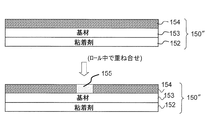
<印字層の引き剥がし防止>
また、本実施形態においては、上述のように印字済み粘着テープ150″が剥離剤層151、基材層153、及び粘着剤層154、をこの順序で含む。この結果、上記印字済み粘着テープロールR2においては、印字層155が形成されている部分では、図8に示すように、印字層155の他方側(例えば上側)表面と粘着剤層154とがロールの径方向に重ね合わせられて接する状態となる。このとき、印字層155と剥離剤層154との密着性が小さいと、前述したように印字済み粘着テープロールR2から印字済み粘着テープ150″が繰り出されて使用されるとき、剥離剤層154に形成された上記印字層155が再び粘着剤層152側へと引き剥がされ、形成済みの印字の内容に悪影響を与える恐れがある。
<Preventing peeling of printed layer>
In the present embodiment, as described above, the printed
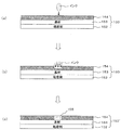
そこで本実施形態においては、前述した手法により、剥離剤層154を、オレフィン樹脂系剥離剤、若しくは、長鎖アルキル基を有するアクリル樹脂系剥離剤で、かつ、重合度が互いに異なる複数種類の重合成分を混合した剥離剤によって構成する。図9(a)に示すように、被印字粘着テープ150の剥離剤層154上にインクジェットヘッド10aからインクが吐出される。このとき、上記剥離剤によって構成された剥離剤層154は、有機高分子多孔質体による剥離剤によって構成されている(すなわち前述の微視的な細孔が、剥離剤層154を構成する分子どうしの間に多数形成されている)。これにより、図9(b)に示すように、(印字層155を構成する)上記インク粒子は、上記剥離剤層154中の上記細孔による隙間内に入り込んで浸透してゆく。この結果、図9(c)に示すように、このインクにより形成される印字層155が、剥離剤層154に対し強固に密着された状態とすることができる。これにより、上記ユーザの使用時における印字済み粘着テープロールR2からの繰り出しの際に、印字層155が、ロール中で隣接する粘着層152側へと引き剥がされるのを防止することができる。この結果、上記形成済みの印字内容への悪影響を防止することができる。
Therefore, in this embodiment, the
以上のように、本実施形態によれば、被印字テープロールR1からの繰り出し時における被印字粘着テープ150の剥離性を向上しつつ、印字済み粘着テープロールR2からの繰り出し時における印字内容への悪影響を防止し、さらに印字済み粘着テープ150″が貼り付けて使用されるときの防汚性を維持できる、最適な特性を容易に実現することができる。
As described above, according to the present embodiment, while improving the peelability of the print-receiving
また、本実施形態においては特に、剥離剤層154において、ポリマー分子鎖の間隙が、30nm以上1000nm以下となっている。これにより、剥離剤層154を構成するポリマー分子どうしの間に、印字層155を構成するインク粒子を確実に入り込ませ、印字層155を剥離剤層154に対し強固に密着させることができる。
In the present embodiment, in particular, in the
また、本実施形態においては特に、印字済み粘着テープ150″の上記印字層155が、例えば、染料により構成されたインク層である。これにより、上記のようにしてインクジェットヘッド10aから吐出された染料のインク粒子を、剥離剤層154を構成する分子どうしの間に確実に入り込ませ、剥離剤層154に対し強固に密着させることができる。
In the present embodiment, in particular, the
なお、以上の説明において、「垂直」「平行」「平面」等の記載がある場合には、当該記載は厳密な意味ではない。すなわち、それら「垂直」「平行」「平面」とは、設計上、製造上の公差、誤差が許容され、「実質的に垂直」「実質的に平行」「実質的に平面」という意味である。 In addition, in the above description, when there are descriptions such as “vertical”, “parallel”, and “plane”, the descriptions are not strict. That is, the terms “vertical”, “parallel”, and “plane” are acceptable in design and manufacturing tolerances and errors, and mean “substantially vertical”, “substantially parallel”, and “substantially plane”. .
また、以上の説明において、外観上の寸法や大きさが「同一」「等しい」「異なる」等の記載がある場合は、当該記載は厳密な意味ではない。すなわち、それら「同一」「等しい」「異なる」とは、設計上、製造上の公差、誤差が許容され、「実質的に同一」「実質的に等しい」「実質的に異なる」という意味である。 In addition, in the above description, when there are descriptions such as “same”, “equal”, “different”, etc., in terms of external dimensions and sizes, the descriptions are not strict. That is, the terms “identical”, “equal”, and “different” mean that “tolerance and error in manufacturing are allowed in design and that they are“ substantially identical ”,“ substantially equal ”, and“ substantially different ”. .
なお、以上において、図4に示す矢印は信号の流れの一例を示すものであり、信号の流れ方向を限定するものではない。 In addition, in the above, the arrow shown in FIG. 4 shows an example of the signal flow, and does not limit the signal flow direction.
また、以上既に述べた以外にも、上記各実施形態や各変形例による手法を適宜組み合わせて利用してもよい。 In addition to those already described above, the methods according to the above embodiments and modifications may be used in appropriate combination.
その他、一々例示はしないが、本発明は、その趣旨を逸脱しない範囲内において、種々の変更が加えられて実施されるものである。 In addition, although not illustrated one by one, the present invention is implemented with various modifications within a range not departing from the gist thereof.
1 粘着テープ印刷装置
10a インクジェットヘッド
150 被印字粘着テープ
150′,150″ 印字済み粘着テープ
151 剥離材
152 粘着剤層(粘着層)
153 基材層(テープ基材層)
154 剥離剤層(剥離層)
155 印字層
R1 被印字テープロール
R2 印字済み粘着テープロール(粘着テープロール)
DESCRIPTION OF
153 Base material layer (tape base material layer)
154 Release agent layer (release layer)
155 Printing layer R1 Printed tape roll R2 Printed adhesive tape roll (adhesive tape roll)
Claims (3)
前記テープ本体が、テープ基材層と、前記テープ基材層の前記厚さ方向の一方側に設けられ所定の粘着剤により構成された粘着層と、前記テープ基材層の前記厚さ方向の他方側に設けられた剥離層と、を有し、
前記剥離層が、
オレフィン樹脂系剥離剤、若しくは、長鎖アルキル基を有するアクリル樹脂系剥離剤であって、かつ、重合度が互いに異なる複数種類の重合成分を混合した剥離剤によって構成されており、
前記印字層が、
前記剥離層の前記他方側に形成されている、
前記印字済み粘着テープを、
前記剥離層を外周側としつつ所定の軸芯回りに巻回して構成されたことを特徴とする粘着テープロール。 A pressure-sensitive adhesive tape having a dimension in the thickness direction and having a tape body and a print layer formed on the tape body by ejection from an inkjet head,
The tape body includes a tape base layer, an adhesive layer provided on one side of the tape base layer in the thickness direction and configured by a predetermined adhesive, and the tape base layer in the thickness direction. A release layer provided on the other side,
The release layer is
It is an olefin resin release agent, or an acrylic resin release agent having a long-chain alkyl group, and is composed of a release agent in which a plurality of polymerization components having different polymerization degrees are mixed,
The printing layer is
Formed on the other side of the release layer,
The printed adhesive tape is
An adhesive tape roll configured to be wound around a predetermined axis while the release layer is on the outer peripheral side.
前記印字済み粘着テープの前記剥離層における、ポリマー分子鎖の隙間が、30nm以上、1000nm以下
であることを特徴とする粘着テープロール。 In the pressure-sensitive adhesive tape roll according to claim 1,
The pressure-sensitive adhesive tape roll, wherein a gap between polymer molecular chains in the release layer of the printed pressure-sensitive adhesive tape is 30 nm or more and 1000 nm or less.
前記印字済み粘着テープの前記印字層が、染料により構成されたインク層である
ことを特徴とする粘着テープロール。 In the pressure-sensitive adhesive tape roll according to claim 1 or 2,
An adhesive tape roll, wherein the printed layer of the printed adhesive tape is an ink layer composed of a dye.
Priority Applications (2)
| Application Number | Priority Date | Filing Date | Title |
|---|---|---|---|
| JP2014072197A JP2015194591A (en) | 2014-03-31 | 2014-03-31 | adhesive tape roll |
| PCT/JP2015/059809 WO2015152102A1 (en) | 2014-03-31 | 2015-03-27 | Adhesive tape roll, adhesive tape printing device, and adhesive tape printing method |
Applications Claiming Priority (1)
| Application Number | Priority Date | Filing Date | Title |
|---|---|---|---|
| JP2014072197A JP2015194591A (en) | 2014-03-31 | 2014-03-31 | adhesive tape roll |
Publications (1)
| Publication Number | Publication Date |
|---|---|
| JP2015194591A true JP2015194591A (en) | 2015-11-05 |
Family
ID=54433676
Family Applications (1)
| Application Number | Title | Priority Date | Filing Date |
|---|---|---|---|
| JP2014072197A Pending JP2015194591A (en) | 2014-03-31 | 2014-03-31 | adhesive tape roll |
Country Status (1)
| Country | Link |
|---|---|
| JP (1) | JP2015194591A (en) |
Citations (5)
| Publication number | Priority date | Publication date | Assignee | Title |
|---|---|---|---|---|
| JPH1180685A (en) * | 1997-09-11 | 1999-03-26 | Nitto Denko Corp | Pressure-sensitive adhesive sheet and label for printing |
| JP2001003009A (en) * | 1999-06-16 | 2001-01-09 | Nitto Denko Corp | Adhesive sheet for printing, label and releasing agent composition |
| WO2004037942A1 (en) * | 2002-10-25 | 2004-05-06 | Mitsubishi Chemical Corporation | Release agent and release sheet |
| JP2005029718A (en) * | 2003-07-08 | 2005-02-03 | Nichiban Co Ltd | Adhesive tape or sheet having functional layer |
| JP2014070089A (en) * | 2012-09-27 | 2014-04-21 | Brother Ind Ltd | Adhesive tape, and adhesive tape roll |
-
2014
- 2014-03-31 JP JP2014072197A patent/JP2015194591A/en active Pending
Patent Citations (5)
| Publication number | Priority date | Publication date | Assignee | Title |
|---|---|---|---|---|
| JPH1180685A (en) * | 1997-09-11 | 1999-03-26 | Nitto Denko Corp | Pressure-sensitive adhesive sheet and label for printing |
| JP2001003009A (en) * | 1999-06-16 | 2001-01-09 | Nitto Denko Corp | Adhesive sheet for printing, label and releasing agent composition |
| WO2004037942A1 (en) * | 2002-10-25 | 2004-05-06 | Mitsubishi Chemical Corporation | Release agent and release sheet |
| JP2005029718A (en) * | 2003-07-08 | 2005-02-03 | Nichiban Co Ltd | Adhesive tape or sheet having functional layer |
| JP2014070089A (en) * | 2012-09-27 | 2014-04-21 | Brother Ind Ltd | Adhesive tape, and adhesive tape roll |
Similar Documents
| Publication | Publication Date | Title |
|---|---|---|
| US9783706B2 (en) | Adhesive tape and adhesive tape roll | |
| US9126448B2 (en) | Ink ribbon and ink ribbon roll | |
| JP6065260B2 (en) | Printed adhesive tape and printed adhesive tape roll | |
| JP6327516B2 (en) | Adhesive tape printing apparatus and adhesive tape printing method | |
| JP2013103428A (en) | Continuous sheet for inkjet, and inkjet printer, and preliminary ejection method for inkjet printer | |
| WO2015152102A1 (en) | Adhesive tape roll, adhesive tape printing device, and adhesive tape printing method | |
| JP2015194591A (en) | adhesive tape roll | |
| JP2015193727A (en) | adhesive tape roll | |
| WO2015182235A1 (en) | Adhesive tape printing device, adhesive tape printing method, adhesive tape roll, and ink ribbon | |
| JP6268532B2 (en) | Printing method of adhesive tape, adhesive tape roll, ink ribbon | |
| JP6226136B2 (en) | Adhesive tape printer, adhesive tape roll, and adhesive tape printing method | |
| JP6278194B2 (en) | Adhesive tape printing method and adhesive tape roll | |
| JP6256762B2 (en) | Adhesive tape printer | |
| JP2015193728A (en) | Adhesive tape printer and printing method of adhesive tape | |
| JP2015223740A (en) | Printing formation method for adhesive tape, adhesive tape roll, and ink ribbon | |
| JP6252773B2 (en) | Adhesive tape cartridge | |
| JP6025033B2 (en) | Adhesive tape and adhesive tape roll | |
| JP2014083826A (en) | Bookbinding tape cassette | |
| JP6269947B2 (en) | Adhesive tape cartridge | |
| WO2015156105A1 (en) | Adhesive tape printing device and adhesive tape cartridge | |
| JP2009226919A (en) | Recording apparatus | |
| JP6376358B2 (en) | Masking tape cartridge, printing masking tape roll, and printing apparatus | |
| JP6098989B2 (en) | Bookbinding sheet | |
| JP2014054773A (en) | Image forming apparatus | |
| JP2016078381A (en) | Medium cartridge and printer |
Legal Events
| Date | Code | Title | Description |
|---|---|---|---|
| A621 | Written request for application examination |
Free format text: JAPANESE INTERMEDIATE CODE: A621 Effective date: 20161122 |
|
| A131 | Notification of reasons for refusal |
Free format text: JAPANESE INTERMEDIATE CODE: A131 Effective date: 20180111 |
|
| A521 | Request for written amendment filed |
Free format text: JAPANESE INTERMEDIATE CODE: A523 Effective date: 20180312 |
|
| A02 | Decision of refusal |
Free format text: JAPANESE INTERMEDIATE CODE: A02 Effective date: 20180323 |