JP2015191788A - Optical fiber composite overhead earth wire - Google Patents
Optical fiber composite overhead earth wire Download PDFInfo
- Publication number
- JP2015191788A JP2015191788A JP2014068390A JP2014068390A JP2015191788A JP 2015191788 A JP2015191788 A JP 2015191788A JP 2014068390 A JP2014068390 A JP 2014068390A JP 2014068390 A JP2014068390 A JP 2014068390A JP 2015191788 A JP2015191788 A JP 2015191788A
- Authority
- JP
- Japan
- Prior art keywords
- optical fiber
- strand
- opgw
- ground wire
- ground
- Prior art date
- Legal status (The legal status is an assumption and is not a legal conclusion. Google has not performed a legal analysis and makes no representation as to the accuracy of the status listed.)
- Granted
Links
- 239000013307 optical fiber Substances 0.000 title claims abstract description 144
- 239000002131 composite material Substances 0.000 title claims abstract description 42
- 230000003287 optical effect Effects 0.000 claims abstract description 69
- 238000002844 melting Methods 0.000 claims abstract description 35
- 230000008018 melting Effects 0.000 claims abstract description 35
- 239000010410 layer Substances 0.000 claims description 102
- 229910000831 Steel Inorganic materials 0.000 claims description 26
- 239000010959 steel Substances 0.000 claims description 26
- 239000011247 coating layer Substances 0.000 claims description 25
- 229910000838 Al alloy Inorganic materials 0.000 claims description 19
- 229910052782 aluminium Inorganic materials 0.000 claims description 19
- XAGFODPZIPBFFR-UHFFFAOYSA-N aluminium Chemical compound [Al] XAGFODPZIPBFFR-UHFFFAOYSA-N 0.000 claims description 19
- 229920002050 silicone resin Polymers 0.000 claims description 4
- 238000010348 incorporation Methods 0.000 abstract 1
- 230000004048 modification Effects 0.000 description 26
- 238000012986 modification Methods 0.000 description 26
- 230000000052 comparative effect Effects 0.000 description 17
- 239000000835 fiber Substances 0.000 description 16
- 125000006850 spacer group Chemical group 0.000 description 16
- 230000001681 protective effect Effects 0.000 description 15
- 238000000034 method Methods 0.000 description 8
- 230000005540 biological transmission Effects 0.000 description 7
- 230000002093 peripheral effect Effects 0.000 description 7
- YCKRFDGAMUMZLT-UHFFFAOYSA-N Fluorine atom Chemical compound [F] YCKRFDGAMUMZLT-UHFFFAOYSA-N 0.000 description 6
- 229910001374 Invar Inorganic materials 0.000 description 6
- 239000004020 conductor Substances 0.000 description 6
- 229910052731 fluorine Inorganic materials 0.000 description 6
- 239000011737 fluorine Substances 0.000 description 6
- 229920005989 resin Polymers 0.000 description 6
- 239000011347 resin Substances 0.000 description 6
- 238000005491 wire drawing Methods 0.000 description 5
- 230000000694 effects Effects 0.000 description 4
- 230000004927 fusion Effects 0.000 description 4
- 239000000463 material Substances 0.000 description 4
- 208000025274 Lightning injury Diseases 0.000 description 3
- 238000011156 evaluation Methods 0.000 description 3
- 238000004519 manufacturing process Methods 0.000 description 3
- 230000007935 neutral effect Effects 0.000 description 3
- RYGMFSIKBFXOCR-UHFFFAOYSA-N Copper Chemical compound [Cu] RYGMFSIKBFXOCR-UHFFFAOYSA-N 0.000 description 2
- VYPSYNLAJGMNEJ-UHFFFAOYSA-N Silicium dioxide Chemical compound O=[Si]=O VYPSYNLAJGMNEJ-UHFFFAOYSA-N 0.000 description 2
- 230000015572 biosynthetic process Effects 0.000 description 2
- 238000005253 cladding Methods 0.000 description 2
- 229910052802 copper Inorganic materials 0.000 description 2
- 239000010949 copper Substances 0.000 description 2
- 230000007423 decrease Effects 0.000 description 2
- 238000010438 heat treatment Methods 0.000 description 2
- 229910001220 stainless steel Inorganic materials 0.000 description 2
- 239000010935 stainless steel Substances 0.000 description 2
- 229910000825 440 stainless steel Inorganic materials 0.000 description 1
- 230000033228 biological regulation Effects 0.000 description 1
- 239000011248 coating agent Substances 0.000 description 1
- 238000000576 coating method Methods 0.000 description 1
- 238000012681 fiber drawing Methods 0.000 description 1
- 238000001192 hot extrusion Methods 0.000 description 1
- 230000001678 irradiating effect Effects 0.000 description 1
- 230000001788 irregular Effects 0.000 description 1
- 239000000155 melt Substances 0.000 description 1
- 229910052751 metal Inorganic materials 0.000 description 1
- 239000002184 metal Substances 0.000 description 1
- 229920001721 polyimide Polymers 0.000 description 1
- 239000009719 polyimide resin Substances 0.000 description 1
- 238000003466 welding Methods 0.000 description 1
Images


Landscapes
- Non-Insulated Conductors (AREA)
- Insulated Conductors (AREA)
- Communication Cables (AREA)
Abstract
Description
本発明は、光ファイバ複合架空地線に関する。 The present invention relates to an optical fiber composite ground wire.
架空送電線路には、落雷による直撃から電力線を保護し、落雷による電流を大地に流すための架空地線が、送電線本線となる電力線の上部である鉄塔の頂部に架線される。近年では、架空地線に情報伝送線路としての役割も併せ持たせるように光ファイバを組み込んだ光ファイバ複合架空地線(以下、OPGWともいう)が開発されている(例えば、特許文献1)。 In the overhead power transmission line, an overhead ground line for protecting the power line from direct strikes caused by lightning strikes and flowing current caused by lightning strikes to the ground is installed on the top of the steel tower, which is the upper part of the power line that becomes the main transmission line. In recent years, an optical fiber composite ground wire (hereinafter also referred to as OPGW) in which an optical fiber is incorporated so that the overhead ground wire can also serve as an information transmission line has been developed (for example, Patent Document 1).
OPGWでは、電力線の電流によってOPGWに誘導電流が誘起されるため、常時的にOPGWが発熱する可能性がある。また、OPGWでは雷の直撃によって素線の溶損や断線が発生する可能性がある。さらに、電力線の地絡時には、電力線とOPGWとが閉回路を形成しOPGWに地絡電流が流れることによって、瞬時的にOPGWが発熱する可能性がある。 In OPGW, an induced current is induced in the OPGW by the current of the power line, so the OPGW may constantly generate heat. Further, in OPGW, there is a possibility that the strands may be melted or disconnected due to direct lightning strikes. Further, when the power line has a ground fault, the power line and the OPGW form a closed circuit, and a ground fault current flows through the OPGW, so that the OPGW may instantaneously generate heat.
そのため、これまでのOPGWに組み込まれる光心線は、例えば特許文献1に記載のように、常時150℃、瞬時300℃に耐えうるよう構成されていた。このような高耐熱性を有する光心線は、OPGWの用途に限定され、それ以外の分野ではほとんど使われていなかったため、高価なものとなっていた。 For this reason, the optical fiber core incorporated in the conventional OPGW has been configured to always withstand 150 ° C. and instantaneously 300 ° C. as described in Patent Document 1, for example. Such an optical fiber having high heat resistance is limited to the use of OPGW, and is rarely used in other fields, so that it is expensive.
本発明の目的は、耐熱温度が低い光心線を組み込むことができる光ファイバ複合架空地線を提供することである。 An object of the present invention is to provide an optical fiber composite ground wire capable of incorporating an optical fiber having a low heat-resistant temperature.
本発明の一態様によれば、
内部に光ファイバ素線が設けられる光心線を有する光ユニット部と、
前記光ユニット部の外側に設けられる地線部と、
を有し、
前記地線部は、
導電率が50%IACS以上である第1素線と、
単位長さ当たりの溶融エネルギーが550J/cmより大きい第2素線と、
を有する
光ファイバ複合架空地線が提供される。
According to one aspect of the invention,
An optical unit having an optical core in which an optical fiber is provided;
A ground wire provided outside the light unit;
Have
The ground wire portion is
A first strand having a conductivity of 50% IACS or higher;
A second strand having a melting energy per unit length greater than 550 J / cm;
An optical fiber composite ground wire is provided.
本発明の他の態様によれば、
内部に光ファイバ素線が設けられる光心線を有する光ユニット部と、
前記光ユニット部の外側に設けられる地線部と、
を有し、
前記地線部は、
前記光ユニット部の外側に設けられる第1地線層と、
前記第1地線層の外側に設けられる第2地線層と、
を有し、
前記第1地線層の導電率は、前記第2地線層の導電率よりも高い
光ファイバ複合架空地線が提供される。
According to another aspect of the invention,
An optical unit having an optical core in which an optical fiber is provided;
A ground wire provided outside the light unit;
Have
The ground wire portion is
A first ground layer provided outside the optical unit;
A second ground layer provided outside the first ground layer;
Have
An optical fiber composite ground wire is provided in which the conductivity of the first ground layer is higher than the conductivity of the second ground layer.
本発明によれば、耐熱温度が低い光心線を組み込むことができる光ファイバ複合架空地線が提供される。 ADVANTAGE OF THE INVENTION According to this invention, the optical fiber composite overhead ground wire which can incorporate the optical core wire with low heat-resistant temperature is provided.
<本発明の第1実施形態>
(1)光ファイバ複合架空地線の構造
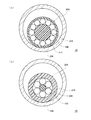
本発明の第1実施形態に係る光ファイバ複合架空地線について、図1を用いて説明する。図1は、本実施形態に係る光ファイバ複合架空地線の軸方向と直交する断面図である。
<First Embodiment of the Present Invention>
(1) Structure of optical fiber composite ground wire The optical fiber composite ground wire according to the first embodiment of the present invention will be described with reference to FIG. FIG. 1 is a cross-sectional view orthogonal to the axial direction of the optical fiber composite ground wire according to the present embodiment.
本実施形態に係る光ファイバ複合架空地線(OPGW:Optical fiber composite overhead ground wire)10は、耐雷性(落雷による耐溶損性)を維持しつつ導電率を高くすることにより、耐熱温度が低い光心線200を組み込むことができるよう構成される。以下、詳細を説明する。
The optical fiber composite ground wire (OPGW) 10 according to the present embodiment is a light having a low heat-resistant temperature by increasing the electrical conductivity while maintaining the lightning resistance (melting resistance against lightning strike). It is configured so that the
なお、以下において、本実施形態の光ファイバ複合架空地線10をOPGW10と略して称する。また、以下において、OPGW10の「軸方向」とはOPGW10の長手方向(延在方向)をいい、OPGW10の「径方向」とはOPGW10の軸方向に垂直な方向、すなわちOPGW10の短手方向をいい、OPGW10の「周方向」とはOPGW10の外周に沿った方向のことをいう。また、「内周面」とは、中心側の面のことをいい、「外周面」とは、内周面と反対側の面のこという。
In the following, the optical fiber
(光ユニット部)
図1に示されているように、OPGW10の中心には、光ユニット部20が設けられる。光ユニット部20の内部には、光ファイバ素線100を有する光心線200が設けられる。なお、本実施形態のOPGW10に組み込むことが可能な光ユニット部20については、詳細を後述する。
(Optical unit)
As shown in FIG. 1, an
(地線部)
光ユニット部20の外側には、地線部30が設けられる。地線部30は、雷撃から電力線(50)および光心線200を保護し、常時誘導電流および地絡時の電流による温度上昇を所定の範囲に抑え、架線時にOPGW10の張力を負担するテンションメンバとして機能するよう構成される。地線部30は、少なくとも2種類の素線を有し、例えば、導電率が高い材料により構成される第1素線320と、耐雷性(落雷による耐溶損性)を有する材料により構成される第2素線420と、を有する。
(Ground line)
A
本実施形態では、地線部30は、2層以上で構成され、第1地線層300および第2地線層400を有する。第1地線層300および第2地線層400には、それぞれ第1素線320および第2素線420が設けられる。以下、地線部30のそれぞれの層について説明する。
In the present embodiment, the
第1地線層300は、光ユニット部20の外側に設けられる。第1素線320が複数撚り合わせられることにより、第1地線層300が設けられる。
The
ここで、第1地線層300の導電率は、第1地線層300の外側に設けられる後述する第2地線層400の導電率よりも高い。
Here, the conductivity of the
本実施形態では、第1地線層300に設けられる第1素線320の導電率は、50%IACS以上である。なお、導電率の単位「%IACS」とは、国際標準軟銅(International Annealed Copper Standard)の導電率を100%としたときの導電率の比率である。本実施形態では、第1素線320の導電率が50%IACS以上であることにより、第1素線320において、電力線(50)から誘起される誘導電流、または地絡時の電流によるジュール熱の発生が抑制される。これにより、OPGW10の温度上昇が抑制される。したがって、OPGW10に組み込まれる光心線200の耐熱温度を低下させることができる。
In the present embodiment, the conductivity of the
具体的には、第1素線320は、例えば、耐熱アルミ合金線(TAL)、超耐熱アルミ合金線(ZTAL)、特別耐熱アルミ合金線(XTAL)および高力耐熱アルミ合金線(KTAL)の少なくともいずれかからなる。耐熱アルミ合金線(TAL)、超耐熱アルミ合金線(ZTAL)、特別耐熱アルミ合金線(XTAL)および高力耐熱アルミ合金線(KTAL)については、社団法人日本電気協会発行「架空送電規程」に記載されている。なお、耐熱アルミ合金線(TAL)、超耐熱アルミ合金線(ZTAL)、特別耐熱アルミ合金線(XTAL)、高力耐熱アルミ合金線(KTAL)のそれぞれの導電率は、60%IACS、60%IACS、58%IACS、55%IACSである。本実施形態の第1素線320は、例えば耐熱アルミ合金線(TAL)である。
Specifically, the
第2地線層400は、第1地線層300の外側に設けられる。第2素線420が複数撚り合わせられることにより、第2地線層400が設けられる。
The
ここで、素線の耐雷性は、素線を完全に溶解させるためのエネルギーとして定義される素線の単位長さ当たりの溶融エネルギーにより評価できることが知られている(例えば特許文献2)。夏季雷の耐電荷量の目標値を200Cとしたとき、素線の単位長さ当たりの溶融エネルギーは約380J/cmであり、冬季雷の耐電荷量の目標値を300Cとしたとき、素線の単位長さ当たりの溶融エネルギーは約550J/cmである。 Here, it is known that the lightning resistance of a strand can be evaluated by the melting energy per unit length of the strand defined as the energy for completely melting the strand (for example, Patent Document 2). When the target value of summer lightning charge resistance is 200 C, the melting energy per unit length of the wire is about 380 J / cm, and when the target value of winter lightning charge resistance is 300 C, The melt energy per unit length is about 550 J / cm.
また、素線の単位長さ当たりの溶融エネルギーEは、以下の式(1)で求められる。 Further, the melting energy E per unit length of the strand is obtained by the following formula (1).
![]()
![]()
ただし、Cは素線を構成する材料の比熱、T0は常温、Tは素線の融点、δは素線の融解熱、Wは素線の単位長さ当たりの重量である。 Where C is the specific heat of the material constituting the strand, T 0 is room temperature, T is the melting point of the strand, δ is the melting heat of the strand, and W is the weight per unit length of the strand.
本実施形態では、式(1)で求められる第2素線420の単位長さ当たりの溶融エネルギーは、550J/cmより大きい。すなわち、第2素線420の単位長さ当たりの溶融エネルギーは、冬季雷による素線の単位長さ当たりの溶融エネルギーの目標値より大きい。これにより、第2素線420が目標とする耐雷性を有するようになる。
In the present embodiment, the melting energy per unit length of the
具体的には、本実施形態では、第2素線420は、例えばアルミニウム被覆鋼線(AC線)からなる。第2素線420は、鋼からなる鋼線440と、鋼線440の外側に設けられアルミニウムからなる被覆層460と、を有する。
Specifically, in this embodiment, the
ここで、第2素線420がAC線である場合、第2素線420の単位長さ当たりの溶融エネルギーEは、以下の式(2)で求められる。
Here, when the
![]()
![]()
ただし、CAlはアルミニウムの比熱、CFeは鋼の比熱、T0は常温、T1はアルミニウムの融点、T2は鋼の融点、δAlはアルミニウムの融解熱、δFeは鋼の融解熱、WAlはアルミニウムからなる被覆層460の単位長さ当たりの重量、WFeは鋼からなる鋼線440の単位長さ当たりの重量である。
Where C Al is the specific heat of aluminum, C Fe is the specific heat of steel, T 0 is room temperature, T 1 is the melting point of aluminum, T 2 is the melting point of steel, δ Al is the heat of fusion of aluminum, and δ Fe is the heat of fusion of steel , W Al is the weight per unit length of the
さらに具体的には、本実施形態では、第2素線420がAC線からなる場合、例えば、第2素線420の導電率は第1素線320の導電率よりも低く、40%IACSである。なお、導電率が40%IACSであるAC線は、「40AC」と呼ばれる。また、第2素線420の直径は4.0mm以上である。なお、40ACにおけるアルミニウムからなる被覆層460の面積比率は62%である。この場合、式(2)より、第2素線420の単位長さ当たりの溶融エネルギーEは、563.4J/cm以上となる。したがって、第2素線420の単位長さ当たりの溶融エネルギーが冬季雷による素線の単位長さ当たりの溶融エネルギーより大きくなり、第2素線420は目標とする耐雷性を有するようになる。
More specifically, in the present embodiment, when the
なお、第2素線420の単位長さ当たりの溶融エネルギーEを550J/cmとするためには、第2素線420が40ACの場合、上述のように第2素線420の直径は4.0mm以上であり、第2素線420が27ACの場合、第2素線420の直径は3.5mm以上であり、第2素線420が14ACの場合、第2素線420の直径は3.2mm以上である必要がある。また、第2素線420が断面扇形などの異形線である場合、第2素線420の単位長さ当たりの溶融エネルギーEを550J/cmとなるように、鋼線440および被覆層460のそれぞれの断面積を設定することが必要である。
In order to set the melting energy E per unit length of the
以上のように構成されるOPGW10の(全体としての)単位長さ当たりの電気抵抗は、例えば0.140Ω/km以下である。これにより、OPGW10の常時温度を100℃以下、瞬時温度を200℃以下とすることができる。したがって、OPGW10に組み込まれる光心線200の耐熱温度を低下させることができる。
The electrical resistance per unit length (as a whole) of the
(具体的寸法)
OPGW10の具体的な寸法としては、光ユニット部20の直径は2mm以上7mm以下であり、例えば4.5mmである。
(Specific dimensions)
As specific dimensions of the
地線部30の第1地線層300における第1素線320の直径は、2mm以上7mm以下であり、例えば4.5mmである。第1地線層300における第1素線320の本数は、4本以上14本以下であり、例えば6本である。
The diameter of the
地線部30の第2地線層400における第2素線420の直径は、3.2mm以上7mm以下であり、例えば4.5mmである。第2地線層400における第2素線420の本数は、6本以上20本以下であり、例えば12本である。
The diameter of the
(2)光ユニット部の構成
上述のように、本実施形態のOPGW10は、耐雷性(落雷による耐溶損性)を維持しつつ導電率を高くすることにより、耐熱温度が低い光心線200を組み込むことができるよう構成される。例えば、本実施形態のOPGW10に組み込まれる光心線200の耐熱温度を、常時100℃以上150℃未満、瞬時200℃以上300℃未満とすることができる。より好ましくは、本実施形態のOPGW10に組み込まれる光心線200の耐熱温度を、常時100℃、瞬時200℃とすることができる。このように耐熱温度が低い光心線200を有する光ユニット部20は、例えば以下のように構成される。
(2) Configuration of Optical Unit As described above, the
まず、光心線200の内部に設けられる光ファイバ素線100について説明する。
First, the
ここで、図2は、本実施形態に係る光ファイバ素線100の軸方向と直交する断面図である。図2に示されているように、光ファイバ素線100は、光ファイバ110と、光ファイバ110を被覆するファイバ被覆層(後述140,150)と、を有する。
Here, FIG. 2 is a cross-sectional view orthogonal to the axial direction of the
光ファイバ110は、コア120およびクラッド130を有する。例えば、コア120は、純石英ガラスからなり、クラッド130は、フッ素添加石英ガラスからなる。また、光ファイバ110は、例えばシングルモード光ファイバである。
The
本実施形態では、ファイバ被覆層は例えば2層により構成される。例えば、光ファイバ110の外側を覆うように、第1ファイバ被覆層140が設けられ、第1ファイバ被覆層140の外周を覆うように第2ファイバ被覆層150が設けられる。
In this embodiment, the fiber coating layer is composed of, for example, two layers. For example, the first
また、第1ファイバ被覆層140および第2ファイバ被覆層150は、例えば、紫外線硬化型のシリコーン樹脂を含む。第1ファイバ被覆層140および第2ファイバ被覆層150の耐熱温度は、常時100℃以上150℃未満、瞬時200℃以上300℃未満、より好ましくは常時100℃瞬時200℃である。
Moreover, the 1st
次に、光心線200について説明する。なお、複数の光ファイバ素線100を一括して束ねたものを光心線200と呼ぶ。
Next, the
ここで、図3(a)は、本実施形態に係る光ユニット部の軸方向と直交する断面図である。図3(a)に示されているように、光心線200は、いわゆる固定型3心一括光心線である。すなわち、光心線200は、3本撚り合わせられる光ファイバ素線100と、光ファイバ素線100の外周を覆うように設けられる素線被覆層210と、を有する。
Here, FIG. 3A is a cross-sectional view orthogonal to the axial direction of the optical unit section according to the present embodiment. As shown in FIG. 3A, the
素線被覆層210は、例えば、フッ素系樹脂を含む。本実施形態では、素線被覆層210の耐熱温度は、常時100℃以上150℃未満、瞬時200℃以上300℃未満、より好ましくは常時100℃瞬時200℃である。
The
このように、本実施形態では、光ファイバ素線100および光心線200を耐熱温度が低い材料により構成することができる。
As described above, in this embodiment, the
次に、光ユニット部20について説明する。
Next, the
図3(a)に示されているように、本実施形態の光ユニット部20は、いわゆるスペーサ型であり、中心にスペーサ280を有する。スペーサ280には、外周側から中心に向かって凹んだ溝部(符号不図示)が設けられる。当該溝部は、例えばスペーサ280の外周に軸方向に沿って螺旋状に設けられる。ここでは、スペーサ280には、例えば3つの溝部が設けられる。また、スペーサ280は、例えばアルミニウムからなる。
As shown in FIG. 3A, the
スペーサ280の当該溝部内には、上記した光ファイバ素線100を有する光心線200が挿通される。また、スペーサ280の外周を被覆するように、保護管290が設けられる。保護管290は、例えばアルミニウムからなる。
In the groove portion of the
(具体的寸法)
光ファイバ素線100の具体的な寸法としては、例えば、光ファイバ110の直径は0.125mmである。第1ファイバ被覆層140の厚さは0.01mm以上0.11mm以下であり、第2ファイバ被覆層150の厚さは0.01mm以上0.11mm以下である。すなわち、光ファイバ素線100の直径は、0.165mm以上0.56mm以下である。
(Specific dimensions)
As specific dimensions of the
光心線200の具体的な寸法としては、例えば、素線被覆層210の厚さは0.05mm以上0.15mm以下である。すなわち、光心線200の直径は、0.46mm以上1.5mm以下である。
As specific dimensions of the
光ユニット部20の具体的な寸法としては、例えば、光ユニット部20のスペーサ280の直径は2mm以上7mm以下であり、保護管290の厚さは0.1mm以上1.0mm以下であり、すなわち、光ユニット部20の直径は2.2mm以上9mm以下であり、例えば4.5mmである。
As specific dimensions of the
(3)光ファイバ複合架空地線の架線構造
(電力線の架線条件)
ここで、図5を用い、本実施形態の電力線50の架線条件について説明する。図5は、鉄塔における光ファイバ複合架空地線および電力線の架線構造を光ファイバ複合架空地線の軸方向から見た図である。図5に示されているように、本実施形態のOPGW10は、電力線50と併設される。以下、電力線50の架線条件と合わせて、電力線50の架線条件が、OPGW10に誘起される誘導電流や、地絡時にOPGW10に流れる電流等に、どのように影響を与えるかについても説明する。
(3) Overhead structure of optical fiber composite overhead ground wire (Power line overhead conditions)
Here, the overhead line conditions of the
OPGW10に併設される電力線50の公称電圧が187kV以上である場合では、電力線50の電流が大きく、OPGW10に誘起される誘導電流が大きい。また、この場合では、OPGW10は、いわゆる直接接地される。すなわち、3相交流の中性点と大地との間は直接接続されており、地絡時にはOPGWに大きな地絡電流が流れる。例えば、本実施形態では、電力線50の公称電圧は、500kVである。
When the nominal voltage of the
また、電力線50のサイズが大きくなると、電力線50の電流容量が増大するため、OPGW10に誘起される誘導電流が大きくなる。例えば、電力線50の公称断面積は、120mm2以上1520mm2以下であり、本実施形態では、電力線50の公称断面積は、国内で標準的に適用される条件として、410mm2である。
Moreover, since the current capacity of the
また、電力線50の耐熱温度が高いと、電力線50の電流容量が増大するため、OPGW10に誘起される誘導電流が大きくなる。例えば、本実施形態では、電力線50は、国内で多く用いられている、耐熱系鋼心アルミニウム撚り線(TACSR)である。
In addition, when the heat resistant temperature of the
また、電力線50の1相当たりの導体数が増えると、電力線50の1相当たりの電流容量が増大するため、OPGW10に誘起される誘導電流が大きくなる。例えば、電力線50の1相当たりの導体500の本数は、1本以上8本以下であり、本実施形態では、電力線50の1相当たりの導体数は、4本である。なお、電力線50の1相当たりの導体数が4本である大きな線路では、OPGW10は例えば2条設けられる。
Further, when the number of conductors per phase of the
また、電力線50の相配列もOPGW10の誘導電流に影響を与える。
The phase arrangement of the
図5に示されているように、鉄塔80には、3相交流の2回線の電力線(送電本線)50が架線されている。図中左側の電力線50を1号線51a,51b,51c、右側の電力線50を2号線52a,52b,52cとすると、各電力線50の3相の相配列は、それぞれ独立して決めることができる。
As shown in FIG. 5, two power lines (power transmission main lines) 50 of three-phase alternating current are installed on the
1号線51a,51b,51c、および2号線52a,52b,52cをそれぞれ同相に配列すると(2回線同相配列)、OPGW10に誘起される誘導電流が大きくなる。そのため、1号線と2号線とを逆相に配列してOPGWに誘起される誘導電流を小さくする場合が多い。本実施形態では、例えば誘導電流が大きくなる厳しい条件として、2回線同相配列とする。
If the
以上のような電力線50の架線条件では、OPGW10に誘起される誘導電流によってOPGW10の常時温度が上昇しやすい可能性がある。さらに、これに重畳して、OPGW10に大きな地絡電流が流れることによってOPGW10の瞬時温度が上昇しやすい可能性がある。本実施形態では、OPGW10の地線部30が2層以上で構成され、上述のように地線部30に導電率が高い第1素線320が設けられることにより、OPGW10の電気抵抗を低下させることができる。したがって、上記のような電力線50の架線条件であっても、誘導電流による常時温度の上昇や、大きな地絡電流による瞬時温度の上昇を抑制することができる。
Under the overhead line conditions of the
(OPGWの架線条件)
本実施形態のOPGW10は、鉄塔80の頂部に接続クランプ(不図示)を介して架線される。上述のように、OPGW10は、例えば2条設けられる。本実施形態のOPGW10は、例えば以下の条件を満たすように架線される。
(OPGW overhead condition)
The
電力線50の送電中に、電力線50から誘起される誘導電流のジュール熱によって上昇するOPGW10の(地線部30の)温度は、100℃以下である。
During transmission of the
また、OPGW10の最大使用張力は、電力線50の温度が最低温度(例えば−15℃)のときに、OPGW10の弛度が電力線50の弛度の80%となるように設定される。このとき、OPGW10の最大使用張力の、OPGW10の引張荷重に対する安全率は2.5以上を確保することが電気設備の技術基準(「電技」と呼ぶ)に規定されており、ここでは、高低差等に対する裕度を考慮して、安全率は例えば2.8である(言い換えれば、OPGW10の最大使用張力はOPGW10の引張荷重の1/2.8倍である)。
The maximum working tension of the
また、地絡時のOPGW10の電流、およびOPGW10への通電時間は、線路設計によって決められる。例えば、地絡時のOPGW10の電流を32kA、OPGW10への通電時間を0.34秒としたとき、OPGW10の(地線部30の)瞬時(到達)温度は、200℃以下である。また、OPGW10の温度が当該瞬時温度となったときのOPGW10の弛度は、電力線50の弛度以下である。
Further, the current of the
(4)光ファイバ複合架空地線の製造方法
次に、本実施形態に係るOPGW10の製造方法について説明する。
(4) Manufacturing method of optical fiber composite ground wire Next, the manufacturing method of OPGW10 which concerns on this embodiment is demonstrated.
(光ファイバ素線形成工程)
まず、光ファイバ線引機を用い、光ファイバプリフォームを加熱炉で溶融し延伸することにより、光ファイバ110を形成する。次に、延伸した光ファイバ110の外周に紫外線硬化型のシリコーン樹脂を被覆して紫外線を照射することを順次2回行うことにより、第1ファイバ被覆層140および第2ファイバ被覆層150を形成する。このように形成された光ファイバ素線100の中間体を金属製のボビンに巻取り、このボビンを恒温槽に投入し、例えば120℃30分間の熱処理を行う。以上により、光ファイバ素線100を形成する。
(Optical fiber forming process)
First, the
(光心線形成工程)
光ファイバ素線100を例えば3本撚り合せ、光ファイバ素線100の外周を覆うように、例えばフッ素系樹脂を含む素線被覆層210を形成する。これにより、光心線200を形成する。
(Optical fiber forming process)
For example, three
(光ユニット部形成工程)
予め軸方向に螺旋状の溝部が形成されたスペーサ280を準備しておき、スペーサ280の溝部に光心線200を挿通させる。次に、光心線200が溝部に挿通されたスペーサ280の外側に、アルミニウムからなるテープを縦添えしてテープ同士の接合部を連続的に溶接および伸管することにより、保護管290を形成する。以上により、光ユニット部20を形成する。
(Optical unit formation process)
A
(第1素線形成工程)
円形の開口を有する伸線ダイスを用い、伸線機により、耐熱アルミニウム合金(TAL)からなる第1素線320を形成する。
(First strand formation process)
A
(第2素線形成工程)
円形の開口を有する伸線ダイスを用い、伸線機により、鋼からなり鋼線440となる鋼線用線材を形成する。次に、熱間押出法により、鋼線440となる鋼線用線材に被覆層460となるアルミニウムを被覆して複合線材を形成する。次に、得られた複合線材を伸線機によって伸線することにより、AC線からなる第2素線420を形成する。
(Second strand forming process)
Using a wire drawing die having a circular opening, a wire rod for
(撚り合せ工程)
次に、光ユニット部20を中心に配置し、光ユニット部20の外周を覆うように、例えば6本の第1素線320を撚り合わせることにより、第1地線層300を形成する。次に、第1地線層300の外周を覆うように、例えば12本の第2素線420を撚り合わせることにより、第2地線層400を形成する。
(Twisting process)
Next, the first
以上により、本実施形態に係るOPGW10が製造される。
As described above, the
(5)本実施形態に係る効果
本実施形態やその変形例によれば、以下に示す1つ又は複数の効果を奏する。
(5) Effects according to the present embodiment According to the present embodiment and its modifications, the following one or more effects are achieved.
(a)本実施形態によれば、光ユニット部20の外側に設けられる地線部30は、導電率が50%IACS以上である第1素線320と、単位長さ当たりの溶融エネルギーEが550J/cmより大きい第2素線420と、を有する。これにより、OPGW10の耐雷性(落雷による耐溶損性)を維持しつつOPGW10の導電率を高くすることにより、OPGW10に耐熱温度が低い光ファイバ素線100を組み込むことができる。
(A) According to the present embodiment, the
ここで、比較例として、これまでのOPGWについて考える。 Here, the conventional OPGW is considered as a comparative example.
OPGWでは、電力線の電流によってOPGWに誘導電流が誘起されるため、常時的にOPGWが発熱する可能性がある。また、OPGWでは、雷の直撃によって素線の溶損や断線が発生する可能性がある。さらに、電力線の地絡時には、電力線とOPGWとが閉回路を形成しOPGWに地絡電流が流れることによって、瞬時的にOPGWが発熱する可能性がある。 In OPGW, an induced current is induced in the OPGW by the current of the power line, so the OPGW may constantly generate heat. Further, in OPGW, there is a possibility that the strands may be melted or disconnected due to a direct lightning strike. Further, when the power line has a ground fault, the power line and the OPGW form a closed circuit, and a ground fault current flows through the OPGW, so that the OPGW may instantaneously generate heat.
そこで、これまでのOPGWでは、地線部における全ての素線が、雷撃を受けた際に溶損や溶融による断線が起こりにくいAC線により構成されていた。しかしながら、地線部における全ての素線がAC線で構成されることによって、これまでのOPGWの導電率は低くなっていた。このため、これまでのOPGWでは、電力線から誘起される誘導電流のジュール熱によって、OPGWの温度が上昇しやすかった。 Therefore, in the conventional OPGW, all the strands in the ground wire portion are constituted by AC wires that are less likely to be broken by melting or melting when subjected to a lightning strike. However, since all the strands in the ground wire portion are composed of AC wires, the conductivity of the OPGW so far has been low. For this reason, in the past OPGW, the temperature of the OPGW was likely to rise due to the Joule heat of the induced current induced from the power line.
したがって、これまでのOPGWに組み込まれる光心線は、例えば上記した特許文献1に記載のように、常時150℃、瞬時300℃に耐えうるよう構成されていた。例えば、これまでのOPGWに組み込まれる光ファイバ素線では、耐熱温度を高くするために、ファイバ被覆層がシリコーン樹脂からなる層とフッ素樹脂からなる層との2層により構成されていたり、ファイバ被覆層がポリイミド樹脂により構成されていたりしていた。また、光心線における素線被覆層が耐熱温度の高いフッ素系樹脂により構成されていた。このような高耐熱性を有する光心線は、OPGWの用途に限定され、それ以外の分野ではほとんど使われていなかったため、高価なものとなっていた。 Therefore, the optical core wire incorporated in the conventional OPGW has been configured to always withstand 150 ° C. and instantaneously 300 ° C. as described in Patent Document 1 described above, for example. For example, in conventional optical fiber strands incorporated in OPGW, in order to increase the heat-resistant temperature, the fiber coating layer is composed of two layers of a silicone resin layer and a fluorine resin layer, The layer was made of polyimide resin. Moreover, the strand covering layer in the optical core was made of a fluorine resin having a high heat resistance temperature. Such an optical fiber having high heat resistance is limited to the use of OPGW, and is rarely used in other fields, so that it is expensive.
これに対して、本実施形態によれば、地線部30を構成する第1素線320の導電率が50%IACS以上であることにより、第1素線320において、電力線(50)から誘起される誘導電流、または地絡時の電流によるジュール熱の発生が抑制される。これにより、OPGW10の温度上昇が抑制される。具体的には、第2素線420が、溶融エネルギーが550J/cm以上を満たす例として、直径が4.0mmの40ACであるとき、第1素線320の導電率が50%IACS以上であることにより、OPGW10全体としての等価導電率を44%IACS以上とすることができ、OPGW10の常時温度を100℃以下、瞬時温度を200℃以下とすることができる。したがって、OPGW10に組み込まれる光心線200の耐熱温度を、これまでのOPGWに組み込まれていた光心線の耐熱温度よりも低下させることができる。
On the other hand, according to the present embodiment, since the conductivity of the
また、地線部30を構成する第2素線420の単位長さ当たりの溶融エネルギーは、550J/cmより大きい。すなわち、第2素線420の単位長さ当たりの溶融エネルギーは、冬季雷による素線の単位長さ当たりの溶融エネルギーより大きい。これにより、第2素線420が耐雷性を有するようになる。したがって、落雷時にも、第2素線420は、溶融することが抑制され、OPGW10の張力を負担し続けることができる。
Moreover, the melting energy per unit length of the
このように、OPGW10の地線部30に第1素線320が設けられることによってOPGW10の導電率が高くなることでOPGW10の温度上昇が抑制され、第2素線420が設けられることによってOPGW10の耐雷性が確保される。これにより、OPGW10に耐熱温度が低い光心線200を組み込むことができる。したがって、本実施形態では、耐熱温度が高い高価な光心線を使用することを回避することができ、OPGW10の製造コストが増大することを抑制することができる。
As described above, the
(b)本実施形態によれば、OPGW10に併設される電力線50の公称電圧は、187kV以上である。このとき、OPGW10の地線部30は、2層以上で構成される。
(B) According to this embodiment, the nominal voltage of the
ここで、比較例として、OPGWに併設される電力線の公称電圧が66kV以上154kV以下である場合について考える。この比較例の場合では、電力線の電流が小さく、OPGWに誘起される誘導電流が小さい。また、比較例のOPGWは、いわゆる抵抗接地される。すなわち、3相交流の中性点と大地との間には大きな電気抵抗が挿入され、地絡時のOPGWの電流が抑制される。したがって、比較例のOPGWでは、地線部を電気抵抗の高い1層のみで構成することができ、OPGWの耐熱温度は、連続90℃、瞬時120℃程度とされる。このように、電力線の公称電圧の違いや接地方式の違いにより、OPGWの耐熱温度を低くすることができる場合がある。 Here, as a comparative example, consider a case where the nominal voltage of the power line provided alongside the OPGW is 66 kV or more and 154 kV or less. In the case of this comparative example, the power line current is small and the induced current induced in the OPGW is small. The OPGW of the comparative example is so-called resistance ground. That is, a large electric resistance is inserted between the neutral point of the three-phase alternating current and the ground, and the current of the OPGW at the time of the ground fault is suppressed. Therefore, in the OPGW of the comparative example, the ground wire portion can be configured by only one layer having high electric resistance, and the heat resistance temperature of the OPGW is set to about 90 ° C. continuously and about 120 ° C. instantaneously. Thus, the heat resistant temperature of the OPGW may be lowered due to the difference in the nominal voltage of the power line and the difference in the grounding method.
これに対して、OPGW10に併設される電力線50の公称電圧が187kV以上である場合では、上述したように、電力線50の電流が大きく、OPGW10に誘起される誘導電流が大きい。また、この場合では、OPGW10は、いわゆる直接接地される。すなわち、3相交流の中性点と大地との間は直接接続されており、地絡時にはOPGWに大きな地絡電流が流れる。したがって、電力線50の公称電圧が187kV以上である場合では、OPGW10に誘起される誘導電流によってOPGW10の常時温度が上昇しやすく、大きな地絡電流が流れることによってOPGW10の瞬時温度が上昇しやすい可能性がある。
On the other hand, when the nominal voltage of the
そこで、本実施形態によれば、OPGW10の地線部30が2層以上で構成され、上述のように地線部30に導電率が高い第1素線320が設けられることにより、OPGW10全体としての電気抵抗を低下させることができる。これにより、電力線50の公称電圧が187kV以上である場合であっても、誘導電流による常時温度の上昇や、大きな地絡電流による瞬時温度の上昇を抑制することができる。したがって、本実施形態は、電力線50の公称電圧が187kV以上である場合に特に有効である。
Therefore, according to the present embodiment, the
(c)本実施形態によれば、地線部30は、光ユニット部20の外側に第1素線320が複数撚り合わせられて設けられる第1地線層300と、第1地線層300の外側に第2素線420が複数撚り合わせられて設けられる第2地線層400と、を有する。
(C) According to the present embodiment, the
ここで、比較例として、本実施形態とは反対に、地線部の外側に位置する第2地線層に、導電率が高い第1素線が設けられ、地線部の内側に位置する第1地線層に耐雷性を有する第2素線が設けられる場合について考える。OPGWが雷撃を受けたとき、雷撃のアーク電流は真っ先に地線部の外側の層(第2地線層)に及ぶ。第2地線層に設けられた導電率が高い第1素線は、充分な耐雷性を有していないため、第2地線層の第1素線が溶断してしまう可能性がある。 Here, as a comparative example, contrary to the present embodiment, the first strand having high conductivity is provided in the second ground layer located outside the ground wire portion, and is located inside the ground wire portion. Consider the case where a second strand having lightning resistance is provided in the first ground layer. When the OPGW receives a lightning stroke, the arc current of the lightning stroke first reaches the outer layer (second ground layer) of the ground line portion. Since the 1st strand with high conductivity provided in the 2nd ground layer does not have sufficient lightning resistance, the 1st strand of the 2nd ground layer may blow out.
これに対して、本実施形態によれば、導電率が高い第1素線320により構成される第1地線層300が、耐雷性を有する第2素線420により構成される第2地線層400によって覆われる。OPGW10が雷撃を受けたとき、耐雷性が低い第1素線320からなる第1地線層300は、第2地線層400によって保護される。したがって、第1地線層300の第1素線320が溶断することを抑制することができる。
On the other hand, according to the present embodiment, the
(d)本実施形態によれば、具体的には、OPGW10の(全体としての)単位長さ当たりの電気抵抗は、0.140Ω/km以下である。これにより、OPGW10の常時温度を100℃以下、瞬時温度を200℃以下とすることができる。したがって、OPGW10に組み込まれる光心線200の耐熱温度を低下させることができる。
(D) According to this embodiment, specifically, the electrical resistance per unit length (as a whole) of the
<本実施形態の変形例>
上述の第1実施形態では、光心線200がいわゆる固定型3心一括光心線である場合について説明したが、本発明はこれに限られるものではない。例えば、以下の変形例のような光心線および光ユニット部の構成が考えられる。なお、光ファイバ素線100の構成は第1実施形態と同様である。以下の変形例では、第1実施形態と異なる要素についてのみ説明し、第1実施形態で説明した要素と実質的に同一の要素には、その説明を省略する。
<Modification of this embodiment>
In the first embodiment described above, the case where the
(変形例1)
図3(b)は、本実施形態に係る光ユニット部の軸方向と直交する断面図である。図3(b)に示されているように、変形例1の光心線202は、いわゆる固定型6心一括光心線である。
(Modification 1)
FIG. 3B is a cross-sectional view orthogonal to the axial direction of the optical unit section according to the present embodiment. As shown in FIG. 3B, the
光心線202の中心には、中心介在物222が設けられる。中心介在物222は、例えばFRPからなる。中心介在物222の外側には、例えば6本の光ファイバ素線100が撚り合わせられる。また、光ファイバ素線100の外周を覆うように、素線被覆テープ232が設けられる。素線被覆テープ232は、例えばフッ素系樹脂を含む。
A
また、変形例1の光ユニット部22のスペーサ282には、例えば5つの溝部が設けられる。スペーサ282の溝部のそれぞれに、光心線202が挿通される。
In addition, for example, five grooves are provided in the
変形例1のように、光ユニット部22は、第1実施形態の光ユニット部20よりも多くの光ファイバ素線100を有していても良い。
Like the modification 1, the
(変形例2)
図4(a)は、変形例2に係る光ユニット部の軸方向と直交する断面図である。図4(a)に示されているように、変形例2の光心線204は、いわゆる非固定型一括光心線である。
(Modification 2)
FIG. 4A is a cross-sectional view orthogonal to the axial direction of the optical unit section according to the second modification. As shown in FIG. 4A, the
光心線204の中心には、テンションメンバ224が設けられる。テンションメンバ224は、例えばFRPからなる。テンションメンバ224の外側には、例えば12本の光ファイバ素線100が撚り合わせられる。また、光ファイバ素線100の外周を覆うように、素線被覆層214が設けられる。素線被覆層214は、例えばフッ素系樹脂を含む。
A
また、変形例2の光ユニット部24では、保護管290内に空隙をあけて光心線204が挿通される。なお、変形例2の場合では、保護管290は、アルミニウムからなる場合のほか、ステンレス、鋼からなっていてもよい。また、保護管290は、アルミニウムが被覆されたステンレス管であってもよい。
Further, in the
変形例2によれば、光心線204が保護管290内を移動することができるため、光心線204の引き換えが可能である。
According to the second modification, the
(変形例3)
図4(b)は、変形例3に係る光ユニット部の軸方向と直交する断面図である。図4(b)に示されているように、変形例3の光心線206も、変形例2と同様に、いわゆる非固定型一括光心線である。
(Modification 3)
FIG. 4B is a cross-sectional view orthogonal to the axial direction of the optical unit section according to Modification 3. As shown in FIG. 4B, the
光心線206の中心には、中心介在物226が設けられる。中心介在物226は、例えばFRPからなる。中心介在物226の外側には、例えば6本の光ファイバ素線100が撚り合わせられる。また、光ファイバ素線100の外周を覆うように、テンションメンバとして機能する素線被覆層216が設けられる。素線被覆層216は、例えばFRPからなる。
A
また、変形例3の光ユニット部26では、変形例2と同様に、保護管290内に空隙をあけて光心線204が挿通される。
Further, in the
変形例3の光ユニット部26のように、光ファイバ素線100の外側にテンションメンバが設けられていても良い。
A tension member may be provided outside the
<本発明の第2実施形態>
図6を用い、本発明の第2実施形態について説明する。図6は、本実施形態に係る光ファイバ複合架空地線の軸方向と直交する断面図である。
<Second Embodiment of the Present Invention>
A second embodiment of the present invention will be described with reference to FIG. FIG. 6 is a cross-sectional view orthogonal to the axial direction of the optical fiber composite ground wire according to the present embodiment.
本実施形態は、第1地線層302の構成が第1実施形態と異なる。以下、第1実施形態と異なる要素についてのみ説明し、第1実施形態で説明した要素と実質的に同一の要素には、同一の符号を付してその説明を省略する。
This embodiment is different from the first embodiment in the configuration of the
(1)光ファイバ複合架空地線の構造
図6に示されているように、本実施形態のOPGW12において、光ユニット部20の外側に設けられる第1地線層302は、例えば断面が扇形である第1素線322を有する。第1素線322は、径方向に沿った側面を有する。なお、「径方向に沿った」とは、「径方向の成分を有する方向に設けられた」と言い換えることができる。第1地線層302に撚り合わせられる複数の第1素線322は、互いに側面で接する(面接触する)。これにより、第1地線層302において、第1素線322が密に充填される。
(1) Structure of optical fiber composite aerial ground wire As shown in FIG. 6, in the
複数の第1素線322が周方向に並んで設けられることによって形成される第1地線層302の内周面は、光ユニット部20の保護管290の外周面に沿った曲面を形成する。第1地線層302の内周面は、光ユニット部20の保護管290に接する(面接触する)。
The inner peripheral surface of the first
(2)本実施形態に係る効果
本実施形態によれば、第1地線層302に撚り合わせられる複数の第1素線322は、互いに側面で接する(面接触する)。第1地線層302において、第1素線322が密に充填される。第1地線層302における第1素線322の断面積を大きくすることができ、第1地線層302の電気抵抗を低くすることができる。第1地線層302において、電力線(50)から誘起される誘導電流、または地絡時の電流によるジュール熱の発生がさらに抑制される。したがって、OPGW10の温度上昇を安定的に抑制することができる。
(2) Effects According to the Present Embodiment According to the present embodiment, the plurality of
<本発明の第3実施形態>
図7を用い、本発明の第3実施形態について説明する。図7は、本実施形態に係る光ファイバ複合架空地線の軸方向と直交する断面図である。
<Third embodiment of the present invention>
A third embodiment of the present invention will be described with reference to FIG. FIG. 7 is a cross-sectional view orthogonal to the axial direction of the optical fiber composite ground wire according to the present embodiment.
本実施形態は、第2地線層404の構成が第1実施形態と異なる。以下、第1実施形態と異なる要素についてのみ説明し、第1実施形態で説明した要素と実質的に同一の要素には、同一の符号を付してその説明を省略する。
This embodiment differs from the first embodiment in the configuration of the
図7に示されているように、本実施形態のOPGW14において、第2地線層404における第2素線424の本数は、第1実施形態の第2素線の本数よりも少なく、例えば10本である。また、第2素線424の直径は、第1実施形態の第2素線の直径よりも大きく、例えば5.3mmである。
As shown in FIG. 7, in the
本実施形態によれば、上述のように、第2素線424の本数が少なく、第2素線424の直径が大きい場合であっても、第1実施形態と同様の効果を得ることができる。
According to the present embodiment, as described above, even when the number of the
<本発明の他の実施形態>
以上、本発明の実施形態および変形例について具体的に説明したが、本発明は上述の実施形態および変形例に限定されるものではなく、その要旨を逸脱しない範囲で種々変更可能である。
<Other Embodiments of the Present Invention>
As mentioned above, although embodiment and modification of this invention were described concretely, this invention is not limited to the above-mentioned embodiment and modification, and can be variously changed in the range which does not deviate from the summary.
上述の実施形態では、OPGW10の地線部30が2層(第1地線層300および第2地線層400)により構成される場合について説明したが、OPGWの地線部は3層以上の地線層を有していても良い。
In the above-described embodiment, the case where the
また、上述の実施形態では、OPGW10の第2素線420がAC線からなる場合について説明したが、第2素線の単位長さ当たりの溶融エネルギーが550J/cmより大きければ、第2素線はAC線以外であってもよい。例えば、第2素線はアルミニウム被覆インバ線であってもよい。この場合、アルミニウム被覆インバ線の溶解エネルギーを求めるには、式(2)において、CFeをインバの比熱、T2をインバの融点、δFeをインバの融解熱、WFeをインバからなる鋼線部の単位長さ当たりの重量に置き換えればよい。
In the above-described embodiment, the case where the
また、上述の実施形態では、第1素線320が耐熱アルミニウム合金からなる場合について説明したが、第1素線は、導電率が50%IACS以上であれば、アルミニウム被覆鋼線からなっていてもよい。
Moreover, although the above-mentioned embodiment demonstrated the case where the
また、上述の実施形態では、第2地線層400を構成する第2素線420の断面は円形である場合について説明したが、第2地線層を構成する第2素線の断面は扇形など異形形状であってもよい。
In the above-described embodiment, the case where the cross section of the
また、上述の実施形態では、光ユニット部20は保護管290を有する場合について説明したが、光ユニット部は保護管を有していなくても良い。
In the above-described embodiment, the case where the
また、上述の実施形態では、光ファイバ素線100のファイバ被覆層は2層(140,150)設けられる場合について説明したが、光ファイバ素線のファイバ被覆層は1層のみであってもよい。
Moreover, although the above-mentioned embodiment demonstrated the case where the fiber coating layer of the
また、上述の実施形態では、光心線200の光ファイバ素線100の外周を覆うように素線被覆層210が設けられる場合について説明したが、光ファイバ素線は、素線被覆層によって覆われていない状態で、スペーサの溝部に収容されていてもよい。変形例3および4においても、光ファイバ素線は、素線被覆層によって覆われていない状態で、保護管内に収容されていてもよい。
Moreover, although the above-mentioned embodiment demonstrated the case where the
(1)OPGWの構成
以下の表1に示されているように、図1に示された第1実施形態に相当するサンプル1のOPGWを設計し、500kV、TACSR410mm2の1相当たり4導体、2回線同相配列された電力線に併設した場合の温度、弛度特性等を検討(評価)した。
(1) Configuration of OPGW As shown in Table 1 below, the OPGW of Sample 1 corresponding to the first embodiment shown in FIG. 1 was designed, and 4 conductors per phase of 500 kV, TACSR 410 mm 2 , We examined (evaluated) the temperature, sag characteristics, etc. when the power lines were arranged in two lines in phase.

また、以下の表2に示されているように、図2に示された第2実施形態に相当するサンプル2のOPGWを設計し特性検討をした。 Further, as shown in Table 2 below, the OPGW of Sample 2 corresponding to the second embodiment shown in FIG.
また、以下の表3に示されているように、図3に示された第3実施形態に相当するサンプル3のOPGWを設計し特性検討をした。 Further, as shown in Table 3 below, the OPGW of Sample 3 corresponding to the third embodiment shown in FIG.
また、以下のように、これまで用いられてきたOPGWの一例として、比較例のOPGWについて検討した。 Further, as an example of the OPGW that has been used so far, the OPGW of the comparative example was examined as follows.
ここで、図8は、比較例に係る光ファイバ複合架空地線の軸方向と直交する断面図である。図8に示されているように、比較例のOPGW90は、光ユニット部92と、地線部93と、を有する。地線部93の構成が、第1実施形態と異なり、地線部93における全ての素線(932,942)は、AC線により構成される。例えば、第1地線層930は、断面が扇形のAC線からなる第1素線932を有し、第2地線層940は、断面が円形のAC線からなる第2素線942を有する。
Here, FIG. 8 is a cross-sectional view orthogonal to the axial direction of the optical fiber composite ground wire according to the comparative example. As illustrated in FIG. 8, the
以下の表4に示されているように、図8に示された比較例のOPGWについて、サンプル1と同条件での温度、弛度特性等を検討した。 As shown in Table 4 below, for the OPGW of the comparative example shown in FIG.
また、以下の表5に示されているように、上記したサンプル1および2に加え、光ユニット部および地線部の構成はサンプル1および2と同じで、断面積が異なる(すなわち、電気抵抗の異なる)サンプル4,5,6のOPGWを設計し、サンプル1と同条件での常時および瞬時の到達温度を検討した。 Further, as shown in Table 5 below, in addition to the samples 1 and 2 described above, the configurations of the optical unit portion and the ground wire portion are the same as those of the samples 1 and 2, and the cross-sectional areas are different (that is, electrical resistance The OPGWs of Samples 4, 5, and 6 were designed, and normal and instantaneous reached temperatures under the same conditions as Sample 1 were examined.
(2)評価内容の詳細
上記したサンプルおよび比較例のOPGWにおいて、以下のような評価を行った。
(2) Details of Evaluation Contents The following evaluation was performed on the above-described sample and the OPGW of the comparative example.
併設した電力線に1相当たり4824Aの電流を流したときの、サンプルおよび比較例のそれぞれのOPGWの常時温度を評価した。このとき、それぞれの地線部には、電力線1相当たりに流れる電流の10%に相当する誘導電流(482.4A)が誘起されるものとした。 The constant temperature of each OPGW of the sample and the comparative example was evaluated when a current of 4824 A per phase was passed through the power line provided. At this time, an induced current (482.4 A) corresponding to 10% of the current flowing per phase of the power line is induced in each ground line portion.
また、電力線50に地絡が生じ、電流を32kA、OPGW10への通電時間を0.34秒としたときの、サンプルおよび比較例のそれぞれのOPGWの瞬時(到達)温度を評価した。
Further, the instantaneous (arrival) temperatures of the OPGW of the sample and the comparative example were evaluated when a ground fault occurred in the
(3)評価結果
表4に示されているように、比較例のOPGWでは、常時温度が114℃であり、瞬時温度が259℃だった。このため、比較例のOPGWに組み込まれる光心線の耐熱温度は、常時150℃、瞬時300℃であることが必要となることが分かる。
(3) Evaluation Results As shown in Table 4, the OPGW of the comparative example always had a temperature of 114 ° C and an instantaneous temperature of 259 ° C. For this reason, it turns out that the heat-resistant temperature of the optical fiber incorporated in the OPGW of the comparative example is required to be constantly 150 ° C. and instantaneously 300 ° C.
これに対して、表1〜3に示されているように、サンプル1〜3では、それぞれ、OPGWの常時温度が96℃,92℃,95℃であり、OPGWの瞬時温度が184℃,167℃,176℃であった。すなわち、サンプル1〜3のいずれにおいても、OPGWの温度が常時100℃以下、瞬時200℃以下であった。したがって、サンプル1〜3のOPGWに組み込まれる光心線の耐熱温度を、比較例のこれまでのOPGWに組み込まれていた光心線の耐熱温度よりも低下させることができることが分かる。 On the other hand, as shown in Tables 1 to 3, in Samples 1 to 3, the constant temperature of OPGW is 96 ° C., 92 ° C., and 95 ° C., and the instantaneous temperature of OPGW is 184 ° C. and 167 ° C., respectively. And 176 ° C. That is, in any of Samples 1 to 3, the OPGW temperature was always 100 ° C. or lower and instantaneously 200 ° C. or lower. Therefore, it can be seen that the heat-resistant temperature of the optical fiber incorporated in the OPGWs of Samples 1 to 3 can be lower than the heat-resistant temperature of the optical fiber incorporated in the conventional OPGW of the comparative example.
なお、サンプル2のOPGWの常時温度および瞬時温度が最も低かった。サンプル2のOPGWでは、第1地線層における第1素線の断面が扇形に形成され、第1素線の断面積が大きかった。したがって、サンプル2のOPGWでは、第1地線層の導電率(OPGWの等価導電率)を高くすることができ、第1地線層において、電力線から誘起される誘導電流、地絡時の電流によるジュール熱の発生がさらに抑制されたことにより、サンプル2のOPGWの常時温度および瞬時温度を低くすることができたと考えられる。 Note that the constant temperature and instantaneous temperature of the OPGW of Sample 2 were the lowest. In the OPGW of Sample 2, the cross section of the first strand in the first ground layer was formed in a fan shape, and the cross-sectional area of the first strand was large. Therefore, in the OPGW of sample 2, the conductivity of the first ground layer (equivalent conductivity of OPGW) can be increased. In the first ground layer, the induced current induced from the power line, the current at the time of the ground fault It is considered that the constant temperature and instantaneous temperature of the OPGW of Sample 2 could be lowered by further suppressing the generation of Joule heat due to.
表5に示されているように、OPGWの断面積が大きくなるにつれて(すなわち、OPGWの単位長さ当たりの電気抵抗が小さくなるにつれて)、OPGWの常時温度および瞬時温度が低くなっていた。特にOPGWの単位長さ当たりの電気抵抗が0.140Ω/km以下であるサンプル1,2では、いずれもOPGWの温度が常時100℃以下、瞬時200℃以下となった。したがって、OPGWの単位長さ当たりの電気抵抗は、0.140Ω/km以下であることが好ましいと考えられる。 As shown in Table 5, as the cross-sectional area of OPGW increases (that is, as the electrical resistance per unit length of OPGW decreases), the constant temperature and instantaneous temperature of OPGW decrease. In particular, in Samples 1 and 2 in which the electrical resistance per unit length of OPGW was 0.140 Ω / km or less, the temperature of OPGW was always 100 ° C. or less and instantaneously 200 ° C. or less. Therefore, it is considered that the electric resistance per unit length of OPGW is preferably 0.140 Ω / km or less.
以上のように、本発明によれば、耐熱温度が低い光心線を組み込むことができるOPGWを提供することができる。 As described above, according to the present invention, it is possible to provide an OPGW that can incorporate an optical fiber having a low heat-resistant temperature.
10 光ファイバ複合架空地線(OPGW)
20,22,24,26 光ユニット部
30 地線部
50 電力線(送電本線)
51a,51b,51c 1号線
52a,52b,52c 2号線
80 鉄塔
100 光ファイバ素線
110 光ファイバ
120 コア
130 クラッド
140 第1ファイバ被覆層
150 第2ファイバ被覆層
200,202,204,206 光心線
210,214,216 素線被覆層
222,226 中心介在物
224 テンションメンバ
232 素線被覆テープ
280,282 スペーサ
290 保護管
300 第1地線層
320,322 第1素線
400,404 第2地線層
420,424 第2素線
440 鋼線
460 被覆層
500 導体
10 Optical fiber composite ground wire (OPGW)
20, 22, 24, 26
51a, 51b, 51c No. 1
Claims (11)
前記光ユニット部の外側に設けられる地線部と、
を有し、
前記地線部は、
導電率が50%IACS以上である第1素線と、
単位長さ当たりの溶融エネルギーが550J/cmより大きい第2素線と、
を有する
ことを特徴とする光ファイバ複合架空地線。 An optical unit having an optical core in which an optical fiber is provided;
A ground wire provided outside the light unit;
Have
The ground wire portion is
A first strand having a conductivity of 50% IACS or higher;
A second strand having a melting energy per unit length greater than 550 J / cm;
An optical fiber composite ground wire characterized by comprising:
前記光ユニット部の外側に前記第1素線が複数撚り合わせられて設けられる第1地線層と、
前記第1地線層の外側に前記第2素線が複数撚り合わせられて設けられる第2地線層と、
を有する
ことを特徴とする請求項1に記載の光ファイバ複合架空地線。 The ground wire portion is
A first ground layer provided by twisting a plurality of the first strands on the outside of the optical unit portion;
A second ground layer provided by twisting a plurality of the second strands outside the first ground layer;
The optical fiber composite ground wire according to claim 1, wherein
前記第1地線層に撚り合わせられる前記複数の第1素線は、互いに前記側面で接する
ことを特徴とする請求項2に記載の光ファイバ複合架空地線。 The first strand has a side surface along a radial direction,
3. The optical fiber composite ground wire according to claim 2, wherein the plurality of first strands twisted together with the first ground layer are in contact with each other at the side surface.
ことを特徴とする請求項1〜3のいずれか1項に記載の光ファイバ複合架空地線。 The electrical resistance per unit length is 0.140 ohm / km or less, The optical fiber composite ground wire of any one of Claims 1-3 characterized by the above-mentioned.
ことを特徴とする請求項1〜4のいずれか1項に記載の光ファイバ複合架空地線。 The optical fiber composite ground wire according to any one of claims 1 to 4, wherein the second strand is made of an aluminum-coated steel wire.
前記第2素線の直径は、3.2mm以上である
ことを特徴とする請求項5に記載の光ファイバ複合架空地線。 The conductivity of the second strand is lower than the conductivity of the first strand,
The diameter of the said 2nd strand is 3.2 mm or more, The optical fiber composite overhead ground wire of Claim 5 characterized by the above-mentioned.
ことを特徴とする請求項1〜6のいずれか1項に記載の光ファイバ複合架空地線。 The said 1st strand consists of at least any one of a heat resistant aluminum alloy wire, a super heat resistant aluminum alloy wire, a special heat resistant aluminum alloy wire, and a high strength heat resistant aluminum alloy wire, The any one of Claims 1-6 characterized by the above-mentioned. An optical fiber composite ground wire according to the item.
ことを特徴とする請求項1〜6のいずれか1項に記載の光ファイバ複合架空地線。 The optical fiber composite ground wire according to any one of claims 1 to 6, wherein the first strand is made of an aluminum-coated steel wire.
ことを特徴とする請求項1〜8のいずれか1項に記載の光ファイバ複合架空地線。 9. The optical fiber composite ground wire according to claim 1, wherein the heat-resistant temperature of the optical fiber is always 100 ° C. or higher and lower than 150 ° C., and instantaneously 200 ° C. or higher and lower than 300 ° C. 9. .
光ファイバと、
前記光ファイバを被覆し紫外線硬化型のシリコーン樹脂を含む被覆層と、
を有する
ことを特徴とする請求項1〜9のいずれか1項に記載の光ファイバ複合架空地線。 The optical fiber is
Optical fiber,
A coating layer that coats the optical fiber and contains an ultraviolet curable silicone resin;
The optical fiber composite overhead ground wire according to any one of claims 1 to 9, characterized by comprising:
前記光ユニット部の外側に設けられる地線部と、
を有し、
前記地線部は、
前記光ユニット部の外側に設けられる第1地線層と、
前記第1地線層の外側に設けられる第2地線層と、
を有し、
前記第1地線層の導電率は、前記第2地線層の導電率よりも高い
ことを特徴とする光ファイバ複合架空地線。 An optical unit having an optical core in which an optical fiber is provided;
A ground wire provided outside the light unit;
Have
The ground wire portion is
A first ground layer provided outside the optical unit;
A second ground layer provided outside the first ground layer;
Have
An optical fiber composite ground wire, wherein the electrical conductivity of the first ground layer is higher than the electrical conductivity of the second ground layer.
Priority Applications (1)
| Application Number | Priority Date | Filing Date | Title |
|---|---|---|---|
| JP2014068390A JP6183264B2 (en) | 2014-03-28 | 2014-03-28 | Optical fiber composite ground wire |
Applications Claiming Priority (1)
| Application Number | Priority Date | Filing Date | Title |
|---|---|---|---|
| JP2014068390A JP6183264B2 (en) | 2014-03-28 | 2014-03-28 | Optical fiber composite ground wire |
Publications (2)
| Publication Number | Publication Date |
|---|---|
| JP2015191788A true JP2015191788A (en) | 2015-11-02 |
| JP6183264B2 JP6183264B2 (en) | 2017-08-23 |
Family
ID=54426126
Family Applications (1)
| Application Number | Title | Priority Date | Filing Date |
|---|---|---|---|
| JP2014068390A Expired - Fee Related JP6183264B2 (en) | 2014-03-28 | 2014-03-28 | Optical fiber composite ground wire |
Country Status (1)
| Country | Link |
|---|---|
| JP (1) | JP6183264B2 (en) |
Cited By (4)
| Publication number | Priority date | Publication date | Assignee | Title |
|---|---|---|---|---|
| CN105913965A (en) * | 2016-05-30 | 2016-08-31 | 国网山东省电力公司聊城供电公司 | Photoelectric hybrid cable |
| CN106024177A (en) * | 2016-05-30 | 2016-10-12 | 尚振兴 | Photoelectric hybrid cable |
| CN106024194A (en) * | 2016-05-30 | 2016-10-12 | 尚振兴 | Photoelectric hybrid cable |
| US9791651B1 (en) * | 2016-09-30 | 2017-10-17 | Ciena Corporation | Reduction of Faraday effect in optical ground wire (OPGW) cables |
Citations (4)
| Publication number | Priority date | Publication date | Assignee | Title |
|---|---|---|---|---|
| JPS61252513A (en) * | 1985-05-01 | 1986-11-10 | Showa Electric Wire & Cable Co Ltd | Optical fiber |
| JPH0562522A (en) * | 1991-04-10 | 1993-03-12 | Fujikura Ltd | Lightning-proof electric wire |
| JPH0973029A (en) * | 1995-07-04 | 1997-03-18 | Sumitomo Electric Ind Ltd | Metallic pipe type optical unit |
| JP2008251267A (en) * | 2007-03-29 | 2008-10-16 | Tokyo Electric Power Co Inc:The | Thunderbolt resistant aerial ground wire |
-
2014
- 2014-03-28 JP JP2014068390A patent/JP6183264B2/en not_active Expired - Fee Related
Patent Citations (4)
| Publication number | Priority date | Publication date | Assignee | Title |
|---|---|---|---|---|
| JPS61252513A (en) * | 1985-05-01 | 1986-11-10 | Showa Electric Wire & Cable Co Ltd | Optical fiber |
| JPH0562522A (en) * | 1991-04-10 | 1993-03-12 | Fujikura Ltd | Lightning-proof electric wire |
| JPH0973029A (en) * | 1995-07-04 | 1997-03-18 | Sumitomo Electric Ind Ltd | Metallic pipe type optical unit |
| JP2008251267A (en) * | 2007-03-29 | 2008-10-16 | Tokyo Electric Power Co Inc:The | Thunderbolt resistant aerial ground wire |
Cited By (4)
| Publication number | Priority date | Publication date | Assignee | Title |
|---|---|---|---|---|
| CN105913965A (en) * | 2016-05-30 | 2016-08-31 | 国网山东省电力公司聊城供电公司 | Photoelectric hybrid cable |
| CN106024177A (en) * | 2016-05-30 | 2016-10-12 | 尚振兴 | Photoelectric hybrid cable |
| CN106024194A (en) * | 2016-05-30 | 2016-10-12 | 尚振兴 | Photoelectric hybrid cable |
| US9791651B1 (en) * | 2016-09-30 | 2017-10-17 | Ciena Corporation | Reduction of Faraday effect in optical ground wire (OPGW) cables |
Also Published As
| Publication number | Publication date |
|---|---|
| JP6183264B2 (en) | 2017-08-23 |
Similar Documents
| Publication | Publication Date | Title |
|---|---|---|
| KR101477720B1 (en) | Electrical conductor and core for an electrical conductor | |
| JP6183264B2 (en) | Optical fiber composite ground wire | |
| CN212380181U (en) | High-temperature-resistant composite cable | |
| WO2012060737A2 (en) | Overhead ground wire with optical communication cable | |
| CN103219070A (en) | XL-ETFE (Cross-linked Ethylene Tetrafluoroethylene) cable for heater | |
| US20170352451A1 (en) | Metal clad cable having parallel laid conductors | |
| CN102915808A (en) | Optical fiber composite overhead ground wire capable of melting ice | |
| CN206601985U (en) | A kind of robot computer drainage flexible cable | |
| JP2010277975A (en) | Superconducting cable line | |
| JP5821892B2 (en) | Multi-core cable and manufacturing method thereof | |
| JP5792120B2 (en) | High-frequency current wire | |
| JP6770459B2 (en) | Superconducting cable | |
| RU2662446C1 (en) | Insulating screening shell | |
| CN110379543B (en) | Conductor, wire and cable | |
| CN209912597U (en) | Ultraviolet irradiation resistant nuclear-grade lighting cable | |
| CN209447566U (en) | A kind of antistatic cable | |
| JP6632954B2 (en) | Grounding system | |
| CN205542086U (en) | Insulating and low smoke zero halogen sheath electric wire of butyronitrile | |
| JP6590507B2 (en) | Optical fiber composite ground wire | |
| CN103354114A (en) | Carbon fiber copper core alloy wire spiral wrapping cable | |
| CN108573776A (en) | coaxial special high-current pulse cable | |
| JP2019067647A (en) | Electric power-cable | |
| JP2003031029A (en) | Overhead electric wire | |
| CN104616741A (en) | High-temperature-resistant flame-retardant tensile electric wire | |
| CN207503704U (en) | A kind of high performance electric vehicle conducting wire |
Legal Events
| Date | Code | Title | Description |
|---|---|---|---|
| A711 | Notification of change in applicant |
Free format text: JAPANESE INTERMEDIATE CODE: A712 Effective date: 20160308 |
|
| A621 | Written request for application examination |
Free format text: JAPANESE INTERMEDIATE CODE: A621 Effective date: 20160928 |
|
| A977 | Report on retrieval |
Free format text: JAPANESE INTERMEDIATE CODE: A971007 Effective date: 20170607 |
|
| TRDD | Decision of grant or rejection written | ||
| A01 | Written decision to grant a patent or to grant a registration (utility model) |
Free format text: JAPANESE INTERMEDIATE CODE: A01 Effective date: 20170627 |
|
| A61 | First payment of annual fees (during grant procedure) |
Free format text: JAPANESE INTERMEDIATE CODE: A61 Effective date: 20170710 |
|
| R150 | Certificate of patent or registration of utility model |
Ref document number: 6183264 Country of ref document: JP Free format text: JAPANESE INTERMEDIATE CODE: R150 |
|
| LAPS | Cancellation because of no payment of annual fees |